Daktronics HS-200WM001 HS-200 Wireless Microphone User Manual
Daktronics, Inc. HS-200 Wireless Microphone Users Manual
Users Manual

OmniSport® is a registered trademark of Daktronics, Inc.
ED12935
Product1056
Rev 4 – 13 February 2002
Copyright
1991, 2002 Daktronics, Inc.
All rights reserved. While every precaution has been taken in the preparation of this
manual, the publisher assumes no responsibility for errors or omissions. No part of this
book covered by the copyrights hereon may be reproduced or copied in any form or by
any means - graphic, electronic, or mechanical, including photocopying, taping, or
information storage and retrieval systems - without written permission of the publisher.
PO Box 5128 331 32nd Ave Brookings SD 57006
Tel 605-697-4400 or 800-843-9879 Fax 605-697-4444
www.daktronics.com e-mail: helpdesk@daktronics.com
Horn Start
HS-200
Operator’s Manual
ED12935

Reproduction Reference
ED12935 – P1056
Horn Start HS-200 Operators Manual
1. This page is for reproduction reference only and will not be included in the manual.
2. Copy this manual on FRONT AND BACK PAGES -8 ½ x 11 paper.
Note: The first page, Cover Page, uses the front of the page (blank on back). Section
heading pages always start on a new page; they never start on the back of another page.
3. Drawing included in this manual:
A-23635
A-26797
A-150431
4. Use a blue window cover and a blue back.
5. Punch all pages, window cover, and manual back along the left edge and bind with a
binder.
6. Please direct question and suggestions to Engineering Secretarial.

Table of Contents i
Table of Contents
Section 1: FCC Compliance Statement ................................................................. 1-1
1.1 HS-200 Wireless Microphone – FCC Compliance statement ....................................1-1
Class A Device Statement ..........................................................................................1-1
Section 2: Introduction ............................................................................................... 2-1
2.1 How To Use This Manual...........................................................................................2-1
Section 3: System Setup ............................................................................................ 3-1
3.1 System Setup ..............................................................................................................3-1
Section 4: Operations ................................................................................................. 4-1
4.1 Operations...................................................................................................................4-1
4.2 Battery Operation........................................................................................................4-1
4.3 Changing the Horn Start Settings ...............................................................................4-2
Section 5: System Storage ......................................................................................... 5-1
5.1 System Storage ...........................................................................................................5-1
Section 6: Accessories ............................................................................................... 6-1
6.1 External Strobe Module..............................................................................................6-1
Battery Operation........................................................................................................6-1
AC Power Operation...................................................................................................6-1
6.2 Wireless Microphone..................................................................................................6-2
HS-200 Wireless Microphone General Operation......................................................6-2
HS-200 Internal Wireless Module (IWM) General Operation ...................................6-3
Section 7: Troubleshooting........................................................................................ 7-1
7.1 Troubleshooting..........................................................................................................7-1
A speaker is not working ............................................................................................7-1
The microphone is not working..................................................................................7-1
The strobe light does not work ...................................................................................7-1
The recall tone does not sound ...................................................................................7-1
The HS-200 will not turn on when attempting to run with battery power..................7-1
Noise Bursts when the Wireless Microphone is being used.......................................7-3
7.2 Unit Exchange/Replacement Procedure .....................................................................7-3
Appendix A: Reference Drawings ...................................................................................A-1

FCC Compliance Statement 1-1
Section 1: FCC Compliance Statement
1.1 HS-200 Wireless Microphone – FCC Compliance statement
Class A Device Statement
(Section 15.105(a) of the FCC Rules)
Note: This equipment has been tested and found to comply with the limits for a Class A digital
device, pursuant to part 15 of the FCC Rules. These limits are designed to provide reasonable
protection against harmful interference when the equipment is operated in a commercial
environment. This equipment generates, uses, and can radiate radio frequency energy and, if not
installed and used in accordance with the instruction manual, may cause harmful interference to
radio communications. Operation of this equipment in a residential area is likely to cause harmful
interference in which case the user will be required to correct the interference at his/her own
expense.
Introduction 2-1
Section 2: Introduction
2.1 How To Use This Manual
The Daktronics HS-200 Horn Start System uses the latest in
electronic components to provide accurate starts for swim timing
applications. The HS-200 provides user controlled voice
amplifications for voice commands and an easily seen start strobe
light. The HS-200 can also interface with a Daktronics’ timing
system or other brands of timers to provide accurate timing.
The HS-200 System comes equipped with:
• HS-200 Horn Start Console............................ 0A-1056-0116
• Hand held dual switch microphone with coiled cord.... 0A-1056-0117
• Power transformer with 10’ cord...................... 0F-1056-0004
• OmniSport Timer output cord (30’).......................... W-1425
• 15’ Microphone Extension............................. 0A-1056-0122
• Horn Start Manual........................................ ED-12935
Important Safeguards:
• Read and understand all instructions.
• Do not drop the control console or allow it to get wet.
• Do not let any power cord to touch hot surfaces or hang over the
edge of a table, which would damage or cut the cord.
• If an extension cord is necessary, use a three-pronged, polarized
cord. Arrange the cord with care so no one will trip over the
cord or pulled it out.
• Always turn off and/or unplug the control equipment when it is
not in use. Never yank the power cord to pull the plug from the
outlet. Grasp the plug and pull to disconnect.
• To avoid electrical shock, do not disassemble the control
equipment or the driver modules. Incorrect reassembly can cause
electric shock and faulty operation or permanent damage to the
circuits.
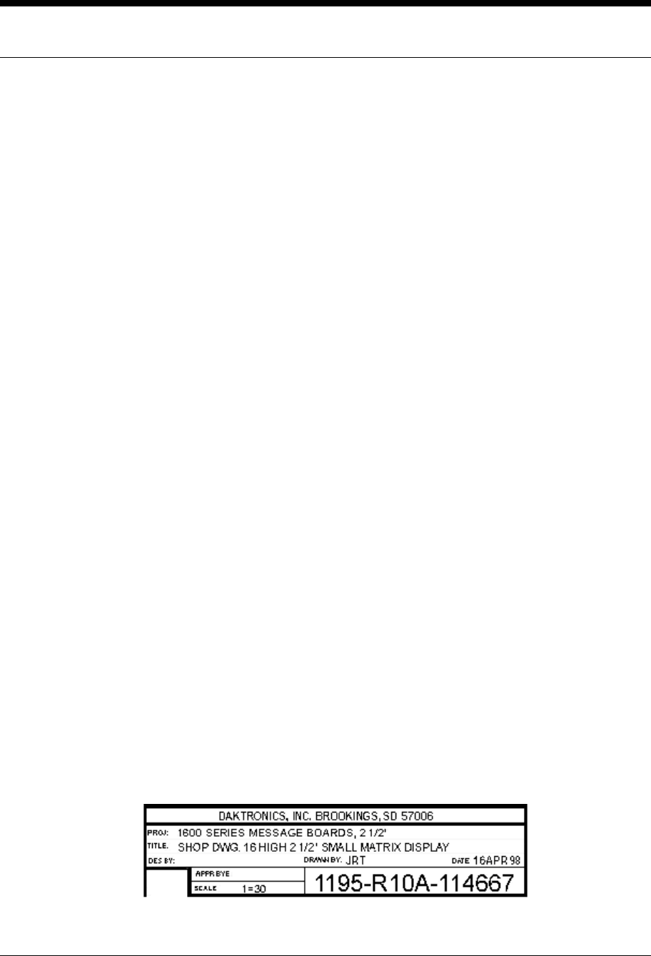
The box below is an illustration of Daktronics drawing numbering
system. The drawing number “ 7087-P08A-69945” is how Daktronics
identifies individual drawings. This number is located in the
bottom right corner of the drawing. The manual will refer to
drawings by the last set digits and the letter preceding them. In
the example, the drawing would be referred to as Drawing A-114667.
All drawings referred to as such will be inserted at the end of each
section.
Figure 1: Daktronics Drawing
Table of Contents
2-2

System Setup 3-1
Section 3: System Setup
3.1 System Setup
Reference Drawings:
Typical Swimming Installation On-Deck.................................................Drawing A-23635
Typical Swimming Installation In-Deck...................................................Drawing A-26797
Refer to Drawings A-23635 and A-26797 for information on typical
placement of system components.
If individual lane speakers are being used, connect them underneath
the starting platforms (individual lane speakers can also be placed
on the wall behind the swimmers). Then string cabling from the HS-
200 to the lane speakers. Carefully secure all cabling from the HS-
200 to the lane speakers. Make sure all cabling on the deck is
secured to prevent injury. Connect the cable into the speaker jacks
marked “ Lane Speaker” on the HS-200 console.
If an auxiliary speaker is being used, place the speaker where
desired and string cable from the HS-200 to the speaker. Connect
the cable into the speaker jack marked “ Aux Speaker” on the HS-200
console.
Connect the timer output cord to the swim timer. If the swim timer
is a Daktronics timer, connect the cord to the timer start jacks
marked “ Daktronics” . If another type of timer is being used,
connect the timer cord to the timer start jacks marked “ N.C.” (For
“ normally closed” output) or “ N.O.” (For “ normally opened”
output) depending on the signal the timer requires.
Connect the microphone to the HS-200 into the jack marked “ Mic.”
Turn on the power to the HS-200 unit.

Operations 4-1
Section 4: Operations
4.1 Operations
Operation of the HS-200 console is very simple and can be mastered
with a few minutes of practice. After installation is complete, turn
on the power to the unit. Set the volume controls as desired for the
main/aux and lane speakers by using the volume control knobs along
the left side of the console.
To speak into the unit, depress the large button on the side of the
microphone, hold the microphone a few inches from your mouth, and
speak directly into the microphone. When not speaking into the
microphone, release the microphone knob.
To activate the Horn Start System, depress the large button on the
side of the microphone and the small button on the top of the
microphone simultaneously.
After a race has been started, the top LED will flash for 18
seconds. This means that if there is a false start the recall signal
can be sounded to notify the swimmers of the false start. To sound
the recall signal, depress the large button on the side of the
microphone and the small button on top of the microphone together
while the recall active LED is on. Refer to Section 3.3 on Start
Recall Settings for information on disabling the recall tone.
4.2 Battery Operation
With a full charge, the HS-200 battery can provide up to 12 hours of continuous operation. When not
in use, plug the HS-200 into a 120VAC outlet to recharge the internal battery. The internal circuitry
monitors the charging process, so leaving the HS-200 plugged in and charging for extended periods
does not damage the internal battery.
The on/off switch on the HS-200 does NOT need to be turned on to charge the internal battery. The
battery charging circuitry will be active whenever the HS-200 is plugged into the wall outlet. When
the HS-200 is plugged in and the on/off switch is turned on, the charging LED will give the battery-
charging status.
If the charging LED is on, the battery is currently being charged. If the charging LED is off (or
flashing) and the Battery Full LED is on, the battery is fully charged.
When battery power runs the HS-200, the Battery Full and Battery Low LEDs give battery status. The
green Battery Full LED is on when the internal battery voltage is above 10.5 volts. If the battery drops
below this voltage, the red Battery Low voltage will be on.
For information about problems with battery charging, please refer to the Troubleshooting section of
this manual.

Operations
4-2
4.3 Changing the Horn Start Settings
The following steps will allow the Horn Start user to enable or disable the recall on the Horn Start:
1. To access the setup, turn the power switch ON and immediately press the “Push to talk” lever (the
button on the side of the microphone) three times.
2. The four LED indicators on the Horn Start will flash, and the speaker will either sound a recall
warbling tone or make no sound at all when the recall is enabled or disabled. This applies no
matter what start sound is selected.
3. To change the setting, press the “Push to talk” button once.
4. To save the current setting press and hold the “Push to talk” button while pressing the top button
twice. The LED’s should quit flashing. The HS-200 is now configured for the selected recall
setting.
The following steps will allow the Horn Start user to configure the unit so it uses the start tone or gun
shot sound:
1. To access the setup, turn the power switch ON and immediately press the “Push to talk” lever (the
button on the side of the microphone) four times.
2. The four LED indicators on the Horn Start will flash and the speaker will sound the current
setting. This sound will be either the tone or the gunshot.
3. To change the setting, press the “Push to talk” button once.
4. To save the current setting, press and hold the “Push to talk” button while pressing the top button
twice. The LED’s should quit flashing.

System Storage 5-1
Section 5: System Storage
5.1 System Storage
The HS-200 console and speakers should be stored in a cool, dry
place, away from the pool environment. All cable should be neatly
coiled and stored away from the pool.
The charging circuit is designed so the battery can be charged for
extended periods, however, it is not required that the HS-200 be
connected to the wall outlet during the off-season. Before storage,
allow the HS-200 to be plugged into the wall outlet for 24 hours to
fully charge the battery. Allow 24 hours of recharge time after the
HS-200 has been taken out of storage as well.

Accessories 6-1
Section 6: Accessories
This section describes some of the accessories that are available with the Horn Start HS-200.
6.1 External Strobe Module
Battery Operation
The HS-200 External Strobe Module includes an internal 12V DC battery that provides up to 12 hours
of continuous use. To use the External Strobe Module on battery power, connect the start input banana
jacks to either a normally open or normally closed switch input such as the HS-200, a push button
switch, or another timing device. To turn the External Strobe module on, connect the banana
connector inputs to the starting device, and press the start button. The green “Power On” LED will
light and the internal buzzer will sound. The External Strobe Module will flash and the buzzer will
sound for each switch input received, provided they occur with at least a 15 second delay. Any switch
inputs received within 15 seconds of the previous switch input will sound the internal buzzer but may
not flash the strobe.
The HS-200 External Strobe Module will run for approximately 30 hours on standby power. In order
to conserve battery life, the External Strobe will turn itself off after one hour with no use. To turn the
strobe back on, simply connect to the starting device and press the start button.
When the internal battery reaches a low level, the red “Low Battery” LED will light for approximately
30 seconds and the External Strobe unit will turn off. Any start signal received after the internal
battery is low will light the low battery LED momentarily.
AC Power Operation
The HS-200 External Strobe Module includes a circuit that will recharge the internal battery when
connected to a 120V AC wall outlet using the 12 V Wall Pack Transformer. When the Strobe Module
is connected to AC power, the green “Power On” LED is on and the strobe is ready for use. The
internal battery will recharge in approximately three to four hours. Due to internal battery monitoring
circuitry, the External Strobe module can be plugged into the wall for extended periods of time
without overcharging. The Amber “Charging” LED is illuminated when the internal battery is being
charged.

Accessories
6-2
6.2 Wireless Microphone
The HS-200 Wireless Microphone is an accessory that allows the starter to direct and start events
without a wired connection to the HS-200. This is possible when the HS-200 is purchased with the
Internal Wireless Module accessory, which is installed in the top center of the HS-200 case.
HS-200 Wireless Microphone General Operation
The Wireless Microphone unit operates identically to the wired microphone and uses the same
microphone assembly. See the “Operations” section of this manual for more information.
Channel Button
The Wireless Microphone also includes a channel button to select the channel used for
transmission to the HS-200 unit. Pressing the channel button on the Wireless Microphone
once shows the current transmit channel on the channel digit. Pressing the button while the
channel number is displayed moves to the next channel. Ordinarily, the HS-200 main unit will
automatically synchronize and change channels with the Wireless Microphone assembly.
Should the main unit fail to synchronize, press the channel button on the main unit until the
channel digit matches the channel shown on the Wireless Microphone. Channels 0-7 are
available for use.
Channel Digit
When the Channel Button is pressed, the Channel Digit shows the current wireless channel.
The decimal point on the channel digit illuminates when the microphone side key is pressed,
indicating that the Wireless Microphone is transmitting data.
Battery Operation
The Wireless Microphone uses two AA batteries for operation. To replace the batteries,
remove the cover on the back of the Wireless Microphone assembly.
The Wireless Microphone should operate for approximately 30-40 hours of meet operation on
one set of batteries. When not in use, the wireless microphone consumes only a minimum
amount of battery power, thus remove batteries when a meet is completed (unless the unit will
be in storage for several months.)
The channel digit shows an “L” when the batteries are low. If an “L” digit appears on the
channel digit, replace the batteries in the unit as soon as possible.

Accessories 6-3
HS-200 Internal Wireless Module (IWM) General Operation
Channel Button
Press the Channel Button on the HS-200 IWM to change the current channel. This channel
will need also need to be selected on the Wireless Microphone assembly. The channel on the
HS-200 IWM should change automatically when a new channel is selected on the Wireless
Microphone.
Carrier LED
The Amber “Carrier” LED on the HS-200 IWM illuminates when radio data (or noise) is
present in the currently selected channel. Before the start of a meet, watch the “Carrier” LED
for any activity other than the HS-200 Wireless Microphone (without pressing the side button
on the Wireless Microphone.) Attempt to choose a channel that has a minimum amount of
interference for best operation.
Valid Receive LED
The Green “Valid Receive” LED on the IWM illuminates when a valid radio packet has been
received from the Wireless Microphone. This LED should be on whenever the Microphone
side button is pressed.

Troubleshooting 7-1
Section 7: Troubleshooting
7.1 Troubleshooting
This section gives detailed information about troubleshooting some of the problems that the HS-200
may have. If you are unable to perform the actions listed in this section, contact Daktronics’ Customer
Service for assistance.
A speaker is not working
Move the speaker in question to a location where one is known to
be working properly. If the speaker in question still does not
work, the speaker is faulty and must be replaced. If the speaker
in question begins to work, the cable that connects to that
speaker is at fault and must be repaired or replaced.
The microphone is not working
Make sure the power is on and that the volume controls are up
high enough to be heard. Press the microphone and start/recall
buttons simultaneously to attempt a start. Disconnect and
reconnect the microphone to ensure a good connection. If either
the start function or microphone still does not work, the
microphone must be replaced. Contact Daktronics’ Customer Service
Department.
The strobe light does not work
Make sure the recall ready LED is on steady. If the Battery Low
indicator is on, plug the HS-200 into the wall outlet and retry.
If the strobe still does not work, contact Daktronics Customer
Service Department.
The recall tone does not sound
Make sure that recall is enabled on the HS-200 unit you are
using. Refer to the section on “ Changing the Horn Start
Settings.”
The HS-200 will not turn on when attempting to run with battery power.
When plugged into the wall outlet the HS-200 operates correctly,
the charging LED is OFF, and Battery Low LED is ON (or flashing).
1. The internal fuse on the HS-200 may be blown. A 21/2
amp AGC
fuse protects the internal battery from short circuit. To
replace this fuse, first make sure to disconnect the HS-200
from the wall outlet, and make sure the power switch is off.
Remove the enclosure cover by removing the 10 screws on the
top, bottom, and side of enclosure. Once the enclosure is open,
disconnect the battery by unplugging the 2-pin Mate-N-Lok™
connector near the bottom center of the printed circuit board.
Remove the fuse next to this connector and replace with an AGC
21/2 amp fuse. Reconnect the battery and close the hornstart
case.
2. The battery may no longer work or may have been severely
damaged due to long periods of usage when the battery was under
power. Plug the hornstart into the wall outlet for 24 hours. If
the same problem occurs, the battery most likely should be

Troubleshooting
7-2
replaced. Contact Daktronics Customer Service.

Troubleshooting 7-3
Noise Bursts when the Wireless Microphone is being used.
There may be another piece of equipment interfering with the wireless microphone. Attempt to
move to a channel with less radio interference. Move to each channel individually and watch the
Amber LED labeled “Carrier LED” on the Internal Wireless Module of the HS-200. Look for a
channel where the Amber LED stays off when the Wireless Microphone is not in operation. If all
channels are noisy, attempt to determine which equipment is interfering by unplugging any
electronic equipment in the area.
7.2 Unit Exchange/Replacement Procedure
To serve customers’ repair and maintenance needs, Daktronics offers both an exchange program and a
repair and return program.
Daktronics’ unique exchange program is a quick, economical service for replacing key components in
need of repair. If a component fails, Daktronics sends the customer a replacement, and the customer,
in turn, sends the failed component to Daktronics. This not only saves money but also decreases
product downtime. Customers who follow the program guidelines explained below will receive this
service.
Daktronics provides this service to ensure users get the most from their Daktronics products. Please
call the Help Desk – 877-605-1115 – if you have questions regarding the exchange program or any
other Daktronics service.
When you call the Daktronics Help Desk, a trained service technician will work with you to solve the
equipment problem. You will work together to diagnose the problem and determine which exchange
replacement part to ship. If, after you make the exchange, the equipment still causes problems, please
contact our Help Desk immediately.
If the replacement part fixes the problem, package the defective part in the same box and wrapping in
which the replacement part arrived, fill out and attach the enclosed UPS shipping document, and
return the part to Daktronics.
In most circumstances, you will be invoiced for the replacement part at the time it is shipped. This bill
is due when you receive it.
Daktronics expects immediate return of an exchange part if it does not solve the problem. The
company also reserves the right to refuse equipment that has been damaged due to acts of nature or
causes other than normal wear and tear.
If the defective equipment is not shipped to Daktronics within 30 working days from the invoice date,
it is assumed you are purchasing the replacement part, and you will be invoiced for it. This second
invoice represents the difference between the exchange price and the full purchase price of the
equipment. The balance is due when you receive the second invoice. If you return the exchange
equipment after 30 working days from the invoice date, you will be credited for the amount on the
second invoice, minus a restocking fee.

Troubleshooting
7-4
≅To avoid a restocking charge, please return the defective equipment within 30 days from the
invoice date.
Daktronics also offers a Repair and Return program for items not subject to exchange.
Return Materials Authorization: To return parts for service, contact your local representative prior
to shipment to acquire a Return Material Authorization (RMA) number. If you have no local
representative, call the Daktronics Help Desk for the RMA. This expedites repair of your component
when it arrives at Daktronics.
Packaging for Return: Package and pad the item well so that it will not be damaged in shipment.
Electronic components such as printed circuit boards should be installed in an enclosure or placed in
an antistatic bag before boxing. (Antistatic foam packaging and circuit-board shipping boxes are
available from Daktronics). Please enclose your name, address, phone number and a clear description
of symptoms.
How to reach us:
Mail:Daktronics, Inc., Customer Service
P.O. Box 5128
331 32nd Avenue
Brookings, SD 57006
Phone:Daktronics Help Desk: 1 (877) 605-1115 (toll free)
or 1 (605) 697-4036
Customer Service Fax:1 (605) 697-4444
E-mail:helpdesk@daktronics.com

Appendix A:
Reference Drawings
A
-1
Appendix A: Reference Drawings
The Daktronics drawing number is located in the bottom right corner of the drawing. This manual
refers to drawings by listing the last set of digits and the letter preceding them.
The following drawings offer specific information pertaining to the Horn Start HS-200 displays. They
are listed in alphanumeric order.
Typical Swimming Installation (on deck) .............................................................Drawing A-23635
Typical Swimming Installation (in deck) .......................................................Drawing A-26797
Horn Start HS-200.....................................................................................Drawing A-150431