Dalian Seaside Door Controlling System T041-315 Remote User Manual MODEL 9357 9367 Manual 2
Dalian Seaside Door Controlling System Co., Ltd Remote MODEL 9357 9367 Manual 2
User manual

1
GARAGE DOOR OPENER
Models 9357·9367
For Residential Use Only
Owner’s Manual
Please read this manual and the enclosed safety materials carefully!
Fasten the manual near the garage door after installation.
The door WILL NOT CLOSE unless The safety is connected and properly aligned.
Periodic checks of the opener are required to ensure safe operation.
The model number label is located on the left side panel of your opener
www.seaside.net.cn DALIAN SEASIDE DOOR CONTROLLING SYSTEM CO.,
LTD.
TABLE OF CONTENTS
Introduction 2-6
Assembly 7-9
Installation 10-18
Install The Wall Control 19-20
Install The Photo Eye Safety System 21-22
Power 23-24
Adjustments 24-28
Operation 29
Wall Control 30
Remote Control 30
To Erase the Memory 30
To Open the Door Manually 31
Maintenance 31
Repair Parts 32-33
Troubleshooting 34
2
WARNING
WARNING WARNING
WARNING
INTRODUCTION
Safety Symbol and Signal Word Review
This garage door opener has been designed and tested to offer safe service provided it is installed, operated,
maintained and tested in strict accordance with the instructions and warnings contained in this manual.
When you see these Safety Symbols and Signal Words on the following pages, they will alert you to
the possibility of serious injury or death if you do not comply with the warnings that accompany them.
The hazard may come from something or from electric shock. Read the warnings carefully.
Mechanical Electrical
When you see this Signal Word on the following pages, it will alert you to the possibility of damage to
your garage door and/or the garage door opener if you do not comply with the cautionary statements
that accompany it. Read them carefully.
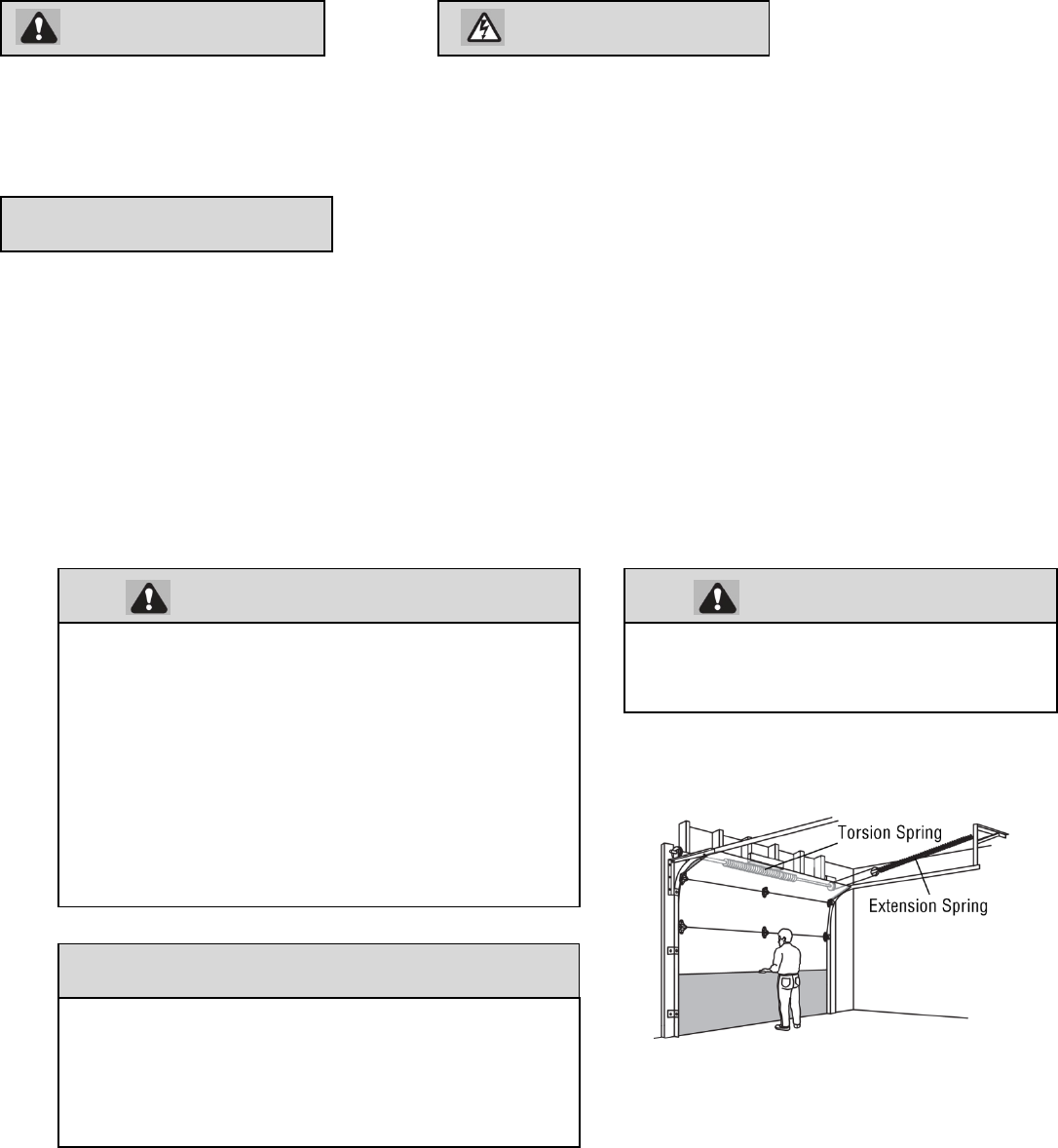
Check your garage door
1 Disable locks and remove any ropes connected to the garage door.
2 Lift the door halfway up. Release the door. If balanced, it should stay in place, supported entirely by its springs.
3 Raise and lower the door to check for binding or sticking. If your door binds, sticks, or is out of balance, call a trained door
systems technician.
4 Check the seal on the bottom of the door. Any gap between the floor and the bottom of the door must not exceed 1/4 inch
(6 mm). Otherwise, the safety reversal system may not work properly.
5 The opener should be installed above the center of the door. If there is a torsion spring or center bearing plate in the way of
the header bracket, it may be installed within 4 feet (1.2 m) to the left or right of the door center. See Installing the Header
Bracket section.
CAUTION
To prevent possible SERIOUS INJURY or DEATH:
ALWAYS call a trained door systems technician if
garage door binds, sticks, or is out of balance. An
unbalanced garage door may not reverse when
required.
NEVER try to loosen, move or adjust garage door,
door springs, cables, pulleys, brackets or their
hardware, ALL of which are under EXTREME
tension.
Disable ALL locks and remove ALL ropes
connected to
d BEFORE i t lli d ti
CAUTION
To prevent damage to garage door and opener:
ALWAYS disable locks BEFORE installing and
operating the opener.
ONLY operate garage door opener at 120V, 60 Hz to
avoid malfunction and damage.
To reduce the risk of injury to persons
Use this operator only with Sectional Door.
3
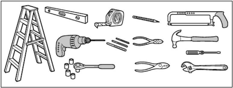
Tools needed
During assembly, installation and adjustment of the opener, instructions will call for hand tools as illustrated below.
4
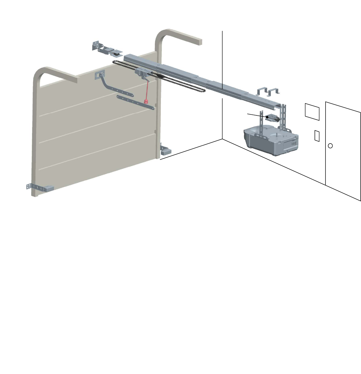
Overview/Carton Inventory
GARAGE DOOR OPENER ASSEMBLY
Overview/Carton Inventory
A B
C
D
E
F
G
H
I
J
K
L
M
N
P
O
Q
A. Header bracket
B. Pulley assembly
C. Door bracket
D. Curved door arm
E. Straight door arm
F. Trolley assembly
G. Emergency release rope and handle
H. Rail
I. Rail Connectors(2)
J. Hanging brackets(2)
K. Garage door opener
L. “U” rail clips(3)
M. Safety reversing sensors
N. Chain
O. Sprocket and sprocket holder assembly
P. Wall Control Panel
Q. Safety labels and literature
5
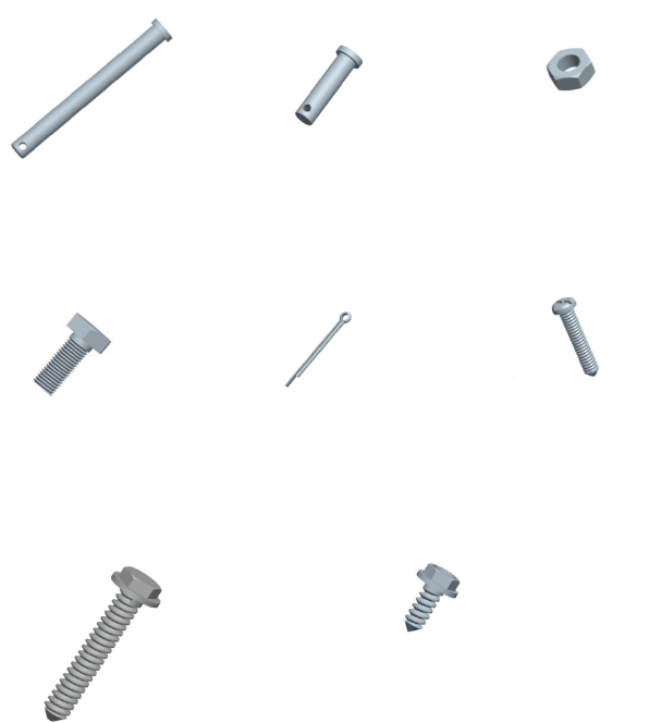
ASSEMBLY HARDWARE
Overview/Carton Inventory
H1 Clevis Pin, long
Φ8×80 (1)
H2 Clevis Pin,short
Φ8×30 (2)
H3 Hex
N
ut
M8(4)
H4 Hex Bolt M8×20(4) H5 CotterΦ2×25(3) H6 Screw M5×20(2)
H7 Lag Screw M8×40 (4) H8 Self-Threading Screw (2)
6
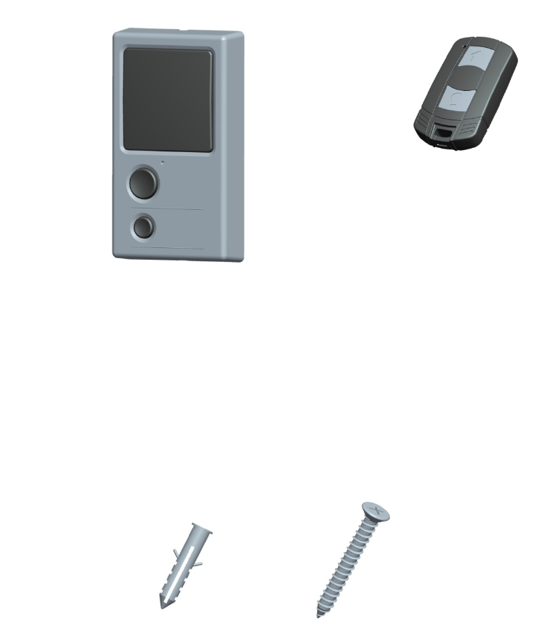
INCLUDED ACCESSORIES
NOTE: Accessories will vary depending on the garage door opener model purchased. Depending on your specific model,
other accessories may be included with your garage door opener. The instructions for these accessories will be attached to
the accessory and are not included in this manual. The images throughout this manual are for reference and your product
may look different.
Wall Control Hardware
ASSEMBLY
Wall Control Panel
Drywall Anchors (2) Screw M4×30 (2)
Remote Control
7
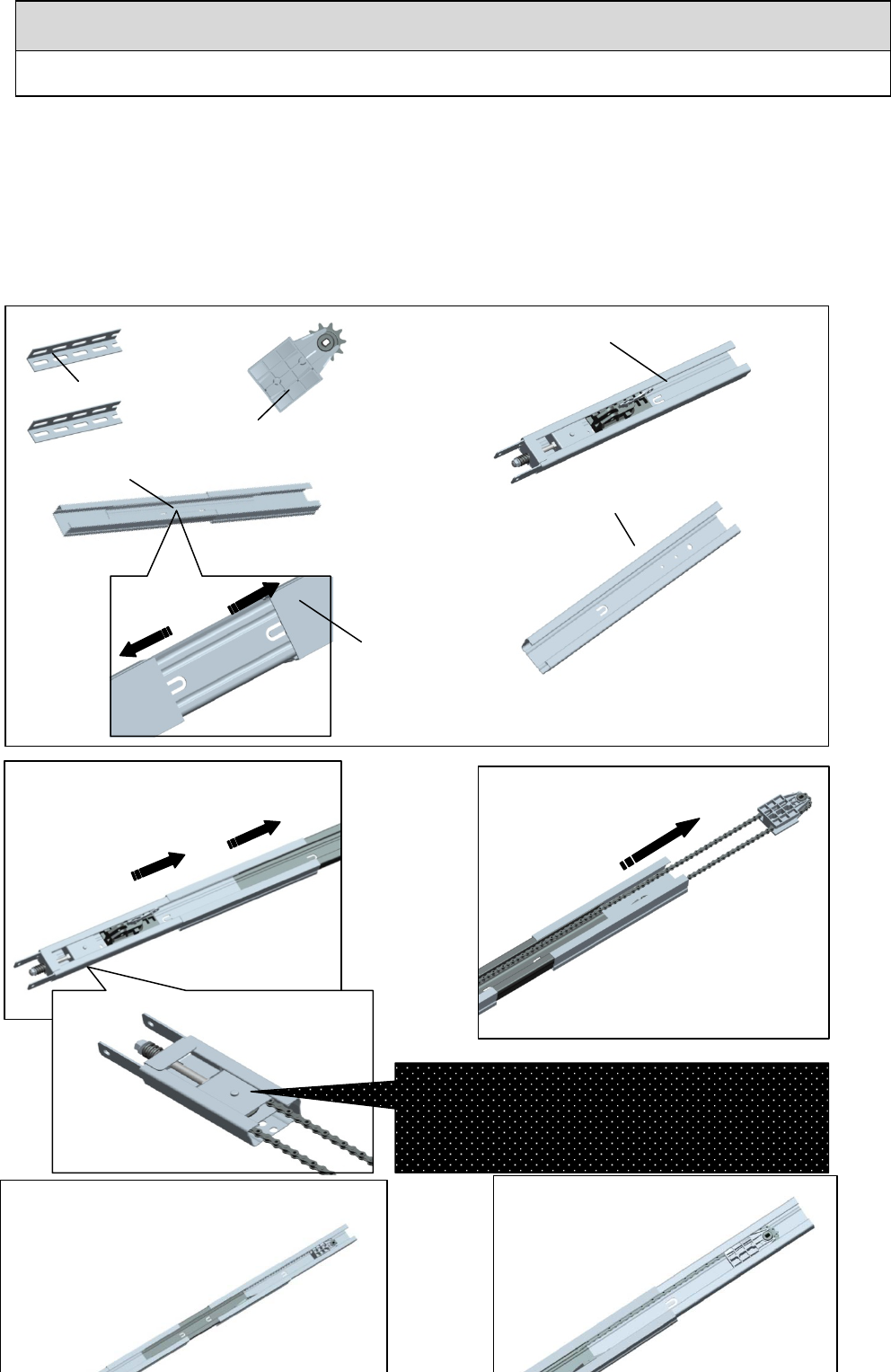
1、Assemble the Rail
To avoid installation difficulties, do not run the garage door opener until instructed to do so.
1.1 Carefully remove the hanging brackets , sprocket and sprocket holder assembly packaged inside the rail.
1.2 Align the rails on a flat surface as shown. The front rail has seven holes
near the
pulley assembly
. The middle rail has two
rail
connectors.
The behind rail has three holes near the end of rail.
1.3 Pull the rail connectors to the “U” hole position in the rail as shown(1).
1.4 Slide the front rail
into the rail
connector. Bend the “U”.
1.5 Pull out the chain, The chain and sprocket assemble together.
1.6 Slide the behing rail
into the rail
connector. Bend the “U”.
1.7 Fasten the sprocket and sprocket holder assembly with the screws (H6).
CAUTION
To prevent INJURY from pinching, keep hands and fingers away from the joints while assembling the rail
Hanging brackets
Sprocket and sprocket holder assembly
Middle Rail
Front
Rail
Behind Rail
Rail connector
3
1
2
4
8
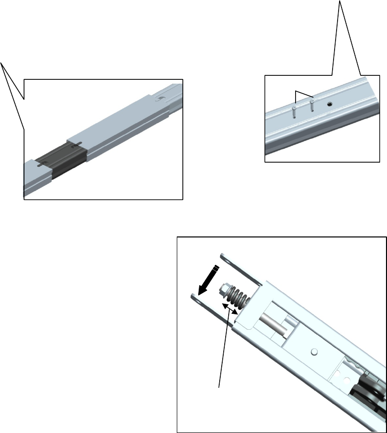
2、Tighten the Chain
ASSEMBLY
H6
6
5
2.1 To increase the tension and tighten the chain,turn the
tension nut clockwise or adjustable wrench until the nut is
spaced properly from the rail end -plate.
2.2 Once the nut is spaced correctly,any additional tightening
will overtighten the chain and may cause damage to the
system.
2.2 To loose the tension,turn nut counterclockwise.
2.5cm
9
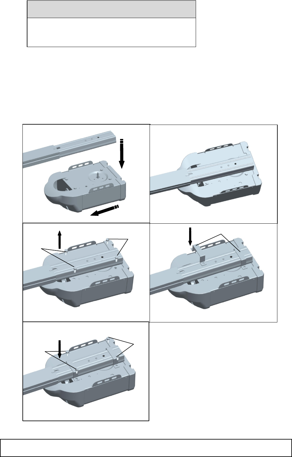
3、Fasten the Rail to the garage door opener
3.1 Position opener with light facing front of garage. Rest opener head on cardboard or protective surface on floor so opener
does not get scratched.Chassis side of opener facing up.
3.2 Position rail onto opener chassis by lining uo rail sprocket,Make sure shaft insert into rail sprocket.Press rail down firmly
onto shaft and opener chassis. DO NOT HAMMER.
3.3 Remove the four bolts(H4) from the chassis of the garage door opener.
3.4 Position 2 “U” rail clips over rail and onto chassis. Insert 4 hex bolts(H4) through rail clips holes and into chassis holes. and
tighten hex bolts firmly to hold rail to the garage door opener head.
INSTALLATION
CAUTION
To avoid SERIOUS damage to garage door opener,
use ONLY those bolts/fasteners mounted in the top of the
opener.
3 “U” rail
IMPORTANT INSTALLATION INSTRUCTIONS
1
4
5
H4
H4
2
H4
H4
10
WARNING
INSTALLATION
1、Determine the Header Bracket Location
To reduce the risk of SEVERE INJURY or
DEATH:
1. READ AND FOLLOW ALL INSTALLATION WARNINGS AND
INSTRUCTIONS.
2. Install garage door opener ONLY on properly balanced and lubricated garage
door.and lubricated garage door. An improperly balanced door may NOT reverse
when required and could result in SEVERE INJURY or DEATH.
3. ALL repairs to cables, spring assemblies and other hardware MUST be made by a
trained door systems technician BEFORE installing opener.
4. Disable ALL locks and remove ALL ropes connected to garage door BEFORE
installing
opener to avoid entanglement.
5. Install garage door opener 7 feet (2.13 m) or more above floor.
6. Mount the emergency release within reach, but at least 6 feet (1.83 m) above the
floor
and avoiding contact with vehicles to avoid accidental release.
7. NEVER connect garage door opener to power source until instructed to do so.
8. NEVER wear watches, rings or loose clothing while installing or servicing opener.
They could be caught In garage door or opener mechanisms.
9. Install wall-mounted garage door control:
· within sight of the garage door.
· out of reach of children at minimum height of 5 feet (1.5 m).
· away from ALL moving parts of the door.
10. Place entrapment warning label on wall next to garage door control.
11. Place manual release/safety reverse test label in pla
in view on inside of garage door.
11
WARNING
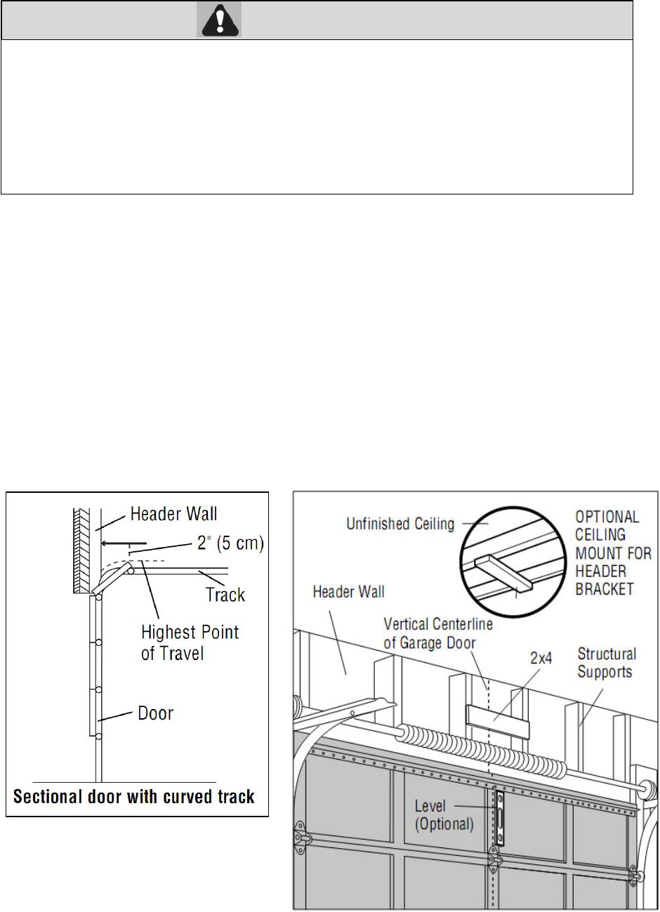
Installation procedures vary according to garage door types. Follow the instructions which apply to your door.
1.1 Close the door and mark the inside vertical centerline of the garage door.
1.2 Extend the line onto the header wall above the door.
You can fasten the header bracket within 4 feet (1.22 m) of the left or right of the door center only if a torsion spring or
center bearing plate is in the way; or you can attach it to the ceiling (see page 13) when clearance is minimal. (It may
be mounted on the wall upside down if necessary, to gain approximately 1/2" (1 cm).
If you need to install the header bracket on a 2x4 (on wall or ceiling), use lag screws (not provided) to securely fasten the
2x4 to structural supports.
1.3 Open your door to the highest point of travel as shown. Draw an intersecting horizontal line on the header wall above the high
point:
2" (5 cm) above the high point for sectional door with track.
NOTE: If the total number of inches exceeds the height available in your garage, use the maximum height possible, or
refer to page 13 for ceiling installation
INSTALLATION
2、Install the Header Bracket
You can attach the header bracket either to the wall above the garage door, or to the ceiling. Follow the instructions which will
work best for your particular requirements. Do not install the header bracket over drywall. If installing into masonry, use
To prevent possible SERIOUS INJURY or DEATH:
· Header bracket MUST be RIGIDLY fastened to structural support on header wall or ceiling,
otherwise garage door might not reverse when required. DO NOT install header bracket over drywall.
· Concrete anchors MUST be used if mounting header bracket or 2x4 into masonry.
· NEVER try to loosen, move or adjust garage door, springs, cables, pulleys, brackets, or their hardware,
ALL of which are under EXTREME tension.
· ALWAYS call a trained door systems technician if garage door binds, sticks, or is out of balance. An
unbalanced
g
ara
g
e door mi
g
ht not reverse when re
q
uired.
12
concrete anchors (not provided).
HARDWARE:
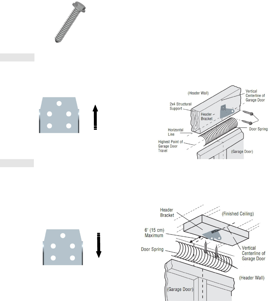
Option A WALL INSTALLATION
2.1A Center the bracket on the vertical centerline with the bottom edge of the bracket on the horizontal line as shown (with the
arrow pointing toward the ceiling).
2.2A Mark the holes. Drill 3/16" pilot holes and fasten the bracket securely to a structural support with the hardware provided.
Option B CEILING INSTALLATION
2.1B Extend the vertical centerline onto the ceiling as shown.
2.2B Center the bracket on the vertical mark, no more than 6" (15 cm) from the wall. Make sure the arrow is pointing away
from the wall. The bracket can be mounted flush against the ceiling when clearance is minimal.
2.3B Mark the holes. Drill 3/16" pilot holes and fasten bracket securely to a structural support with the hardware provided.
INSTALLATION
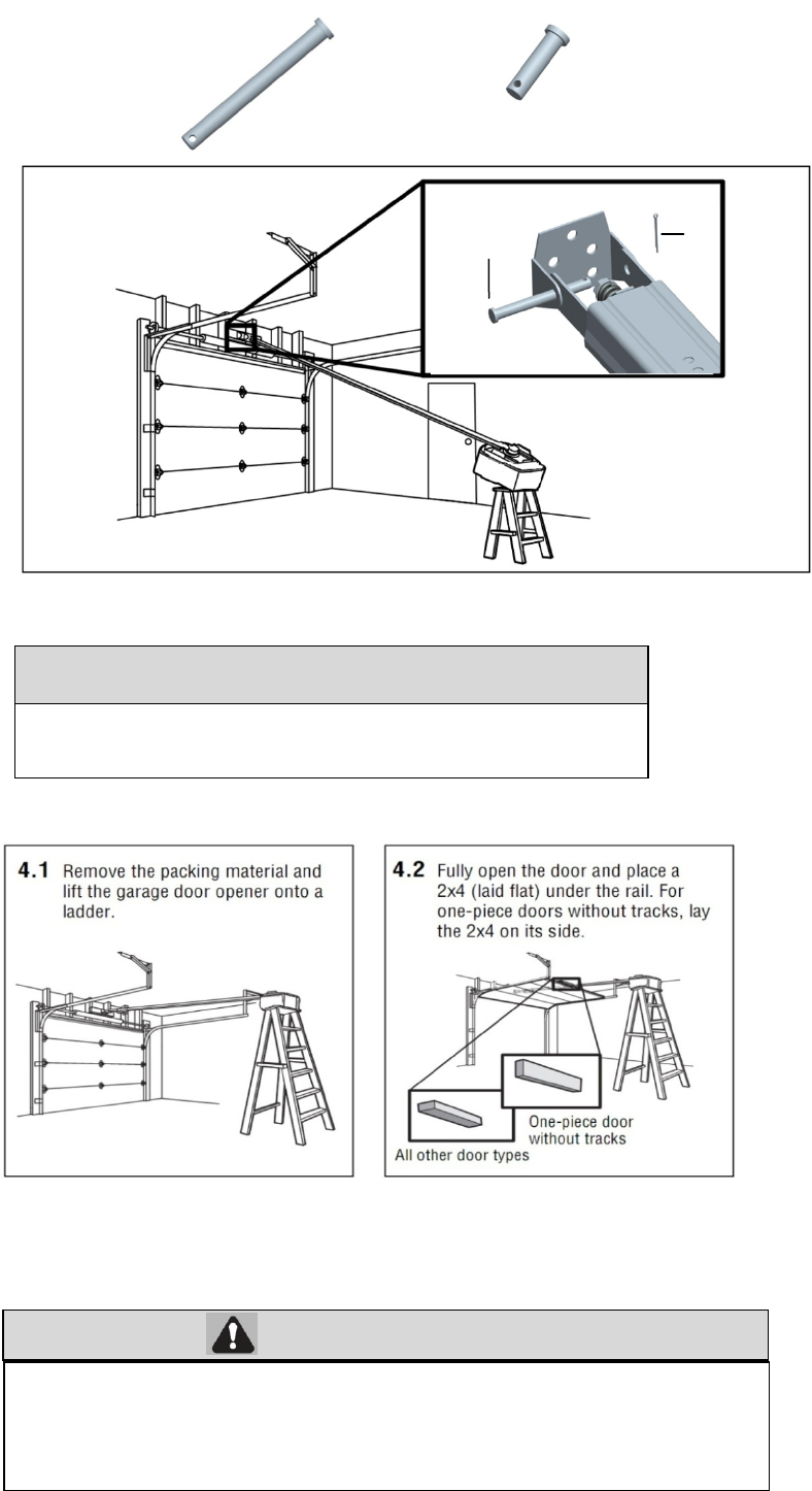
3、Attach the Rail to the Header Bracket
3.1 Align the rail with the header bracket. Insert the clevis pin (H1) through the holes in the header racket and rail. Secure
with the cottor (H5).
H7
H7
H7 Lag Screw M8×40 (2)
H1 Clevis Pin, long
Φ8×80 (1)
H5 CotterΦ2×25(1)
13
WARNING
HAEDWARE
4、Position the garage door opener
NOTE A 2x4 is ideal for setting the distance between the rail and the door. If the ladder is not tall enough you will need
help at this point.
If the door hits the trolley when it is raised, pull the trolley release arm down to disconnect the chain connector kit and trolley.
Slide the trolley toward the garage door opener. The trolley can remain disconnected until further instruction.
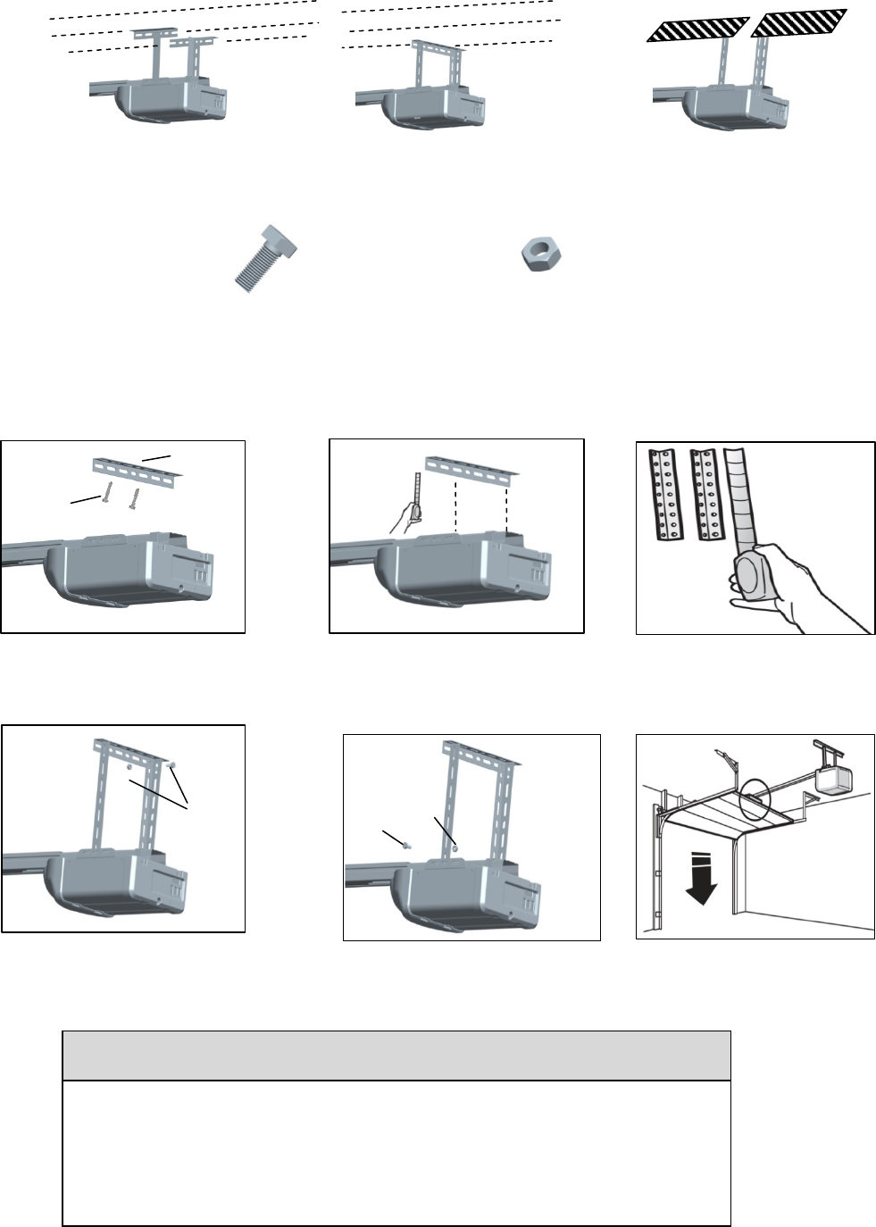
5、Hang the garage door opener
To avoid possible SERIOUS INJURY from a falling garage door opener, fasten it
SECURELY to structural supports of the garage. Concrete anchors MUST be used if
installing ANY brackets into masonry.
CAUTION
To prevent damage to garage door, rest garage door opener rail on 2x4
p
laced on to
p
section of door.
H5
H1
14
Hanging the garage door opener will vary depending on your garage. Below are three example installations. Your
installation may be different. For ALL installations the garage door opener MUST be connected to structural supports. The
instructions illustrate one of the examples below.
HARDWARE
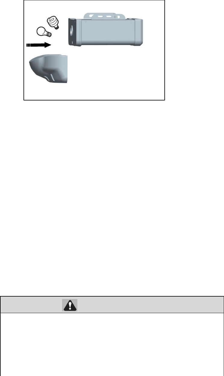
6、Install the light bulbs
CAUTION
To prevent possible OVERHEATING of the end panel or light socket:
· Use ONLY A19 incandescent or compact fluorescent light bulbs.
· DO NOT use incandescent bulbs larger than 100W.
· DO NOT use compact fluorescent light bulbs larger than 26W (100W)equivalent.
· DO NOT use halogen bulbs.
· DO NOT use short neck or s
p
ecialt
y
li
g
ht bulbs.
Fi
n
i
s
h
e
d
C
e
ili
ng
U
n
f
i
n
i
s
h
e
d
C
e
ili
ng
5.1On finished ceilings, use the lag
screws (H7) to attach a support
bracket (not provided) to the
structural supports before installing
the garage door opener
5.2 Make sure the garage door opener
is aligned with the header bracket.
Measure the distance from each
side of the garage door opener to
the support bracket.
5.3 Cut both pieces of the hanging
b
racket to re
q
uired len
g
ths.
H7
Not
p
rovide
d
5.4 Attach the end of each hanging
aligned bracket to the support bracket
with appropriate hardware (not
provided).
5.5 Attach the garage door opener to
the hanging brackets with the bolts
(H15), lock washers (H21) and nuts
(H20).
5.6 Remove the 2x4 and manually close
the door. If the door hits the rail,
raise the header bracket.
Not
p
rovide
d
H4
H4 Hex Bolt M8×20(2) H3 Hex
N
ut
H3
15
WARNING
NOTE: The use of short neck or speciality light bulbs may overheat the end panel or light socket.
6.1 Pull the top sides of the light lens and rotate the light lens down.
6.2 Insert an A19 incandescent or compact fluorescent light bulb (100 watt maximum), into the light socket.
6.3 Clip the lens in the opener.
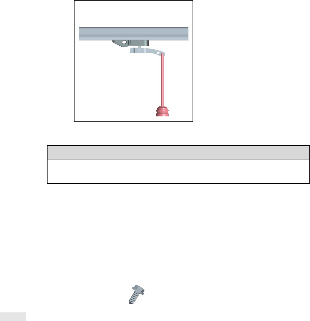
7、Attach the Emergency Release Rope and Handle
To prevent possible SERIOUS INJURY or DEATH from a falling garage door:
If possible, use emergency release handle to disengage trolley ONLY when garage
door is CLOSED. Weak or broken springs or unbalanced door could result in an open
door falling rapidly and/or unexpectedly.
NEVER use emergency release handle unless garage doorway is clear of persons and
obstructions.
NEVER use handle to pull door open or closed. If rope knot becomes untied, you
could fall
OR
16
NOTE:
If it is necessary to cut the emergency release rope, seal the cut end with a match or
lighter to prevent unraveling.
Ensure that the emergency release rope and handle are above
the top of all vehicles to avoid entanglement.
7.1 Insert one end of the emergency release rope through the handle. Tie a knot at least 1 inch (2.5 cm) from the end of the
emergency release rope.
7.2 Insert the other end of the emergency release rope through the hole in the trolley release arm. Make sure the handle is 6 feet
(1.83 m) above the floor and secure with a knot.
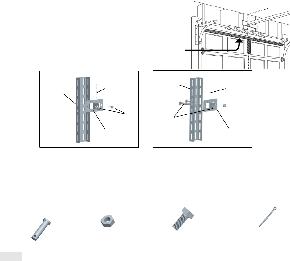
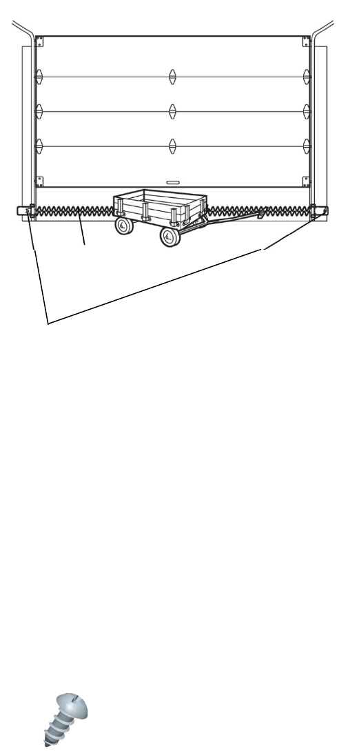
8、Install the door bracket
Figure 1 shows one piece of angle iron as the horizontal brace. For the vertical brace, 2 pieces of angle iron are used to
create a U-shaped support. The best solution is to check with your garage door manufacturer for an opener installation door
reinforcement kit.
NOTE: Many door reinforcement kits provide for direct attachment of the clevis pin and door arm. In this case you will not
need the door bracket; proceed to the next step.
HARDWARE
Option SECTIONAL DOORS
CAUTION
Fiberglass, aluminum or lightweight steel garage doors WILL REQUIRE reinforcement
BEFORE installation of door bracket. Contact your door manufacturer for reinforcement kit.
H8 Self-Threading Screw (2)
17
8.1A Center the door bracket on the previously marked vertical centerline used for the header bracket installation.
Note correct UP placement, as stamped inside the bracket.
8.2A Position the top edge of the bracket 2"-4" (5-10 cm) below the top edge of the door, OR directly below any
structural support across the top of the door.
8.3A Mark, drill holes and install as follows, depending on your door’s construction:
Metal or light weight doors using a vertical angle iron brace between the door panel support and the door bracket:
· Drill 3/16" fastening holes. Secure the door bracket using the two self-threading screws (H16). (Figure 2)
· Alternately, use two 5/16" bolts, lock washers and nuts (not provided). (Figure 3)
Metal, insulated or light weight factory reinforced doors:
· Drill 3/16" fastening holes. Secure the door bracket using the self-threading screws (H16). (Figure 4)
Wood Doors:
· Use top and bottom or side to side door bracket holes. Drill 5/16" holes through
the door and secure bracket with
5/16"x2" carriage bolts, lock washers and nuts
(not provided). (Figure 5)
NOTE:
The 1/4"-14x5/8" self-threading screws are not intended for use on wood
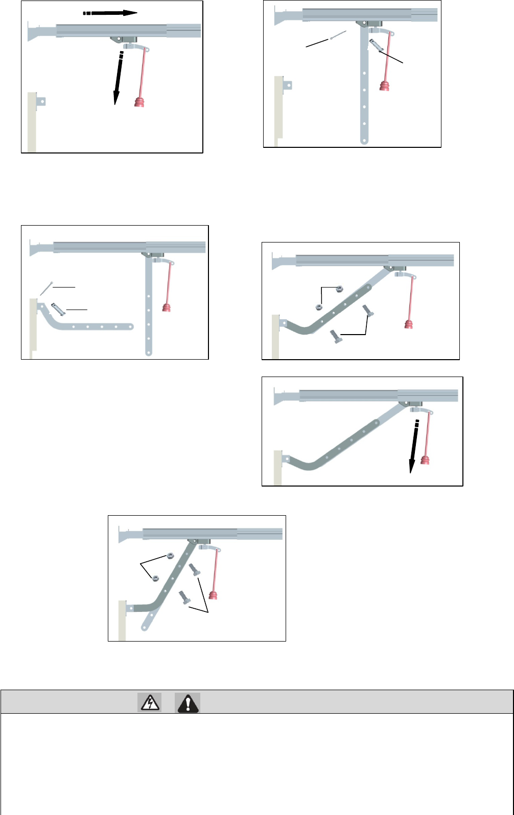
9、Connect the door arm to the trolly
HARDWARE
Option SECTIONAL DOORS
NOTE
:If the holes in the curved door arm and the straight door arm do not align, reverse the
straight door arm, select two
holes (as far apart as possible) and attach using bolts (H15), nuts (H20), and lock washers (H21).
A horizontal and vertical reinforcement is needed for
lightweight garage doors (fiberglass, aluminum, steel,
doors with glass panel, etc.) (not provided). A horizontal
reinforcement brace should be long enough to be secured to
two or three vertical supports. A vertical reinforcement
brace should cover the height of the top panel.
Vertical
Reinforceme
nt
Vertical Centerline
of Garage Door
H8
Vertical
Reinforcement
Vertical Centerline
of Garage Door
Bolt 5/16"
Nut 5/16"
(not provided)
H2 Clevis Pin,short
Φ8×30 (2)
H5 CotterΦ2×25(2)
H3 Hex
N
ut
M8(2) H4 Hex Bolt M8×20(4)
9.1 Close the door. Disconnect the rolley by
pulling the emergency release handle.
9.2 Attach the straight door arm to the outer trolley using
the clevis pin (H14). Attach with the ring fastener
(H19).
Door Bracket
Door Bracket
18
WARNING
If the straight door arm is hanging down too far, you may cut 6 inches (15 cm) from the solid end.
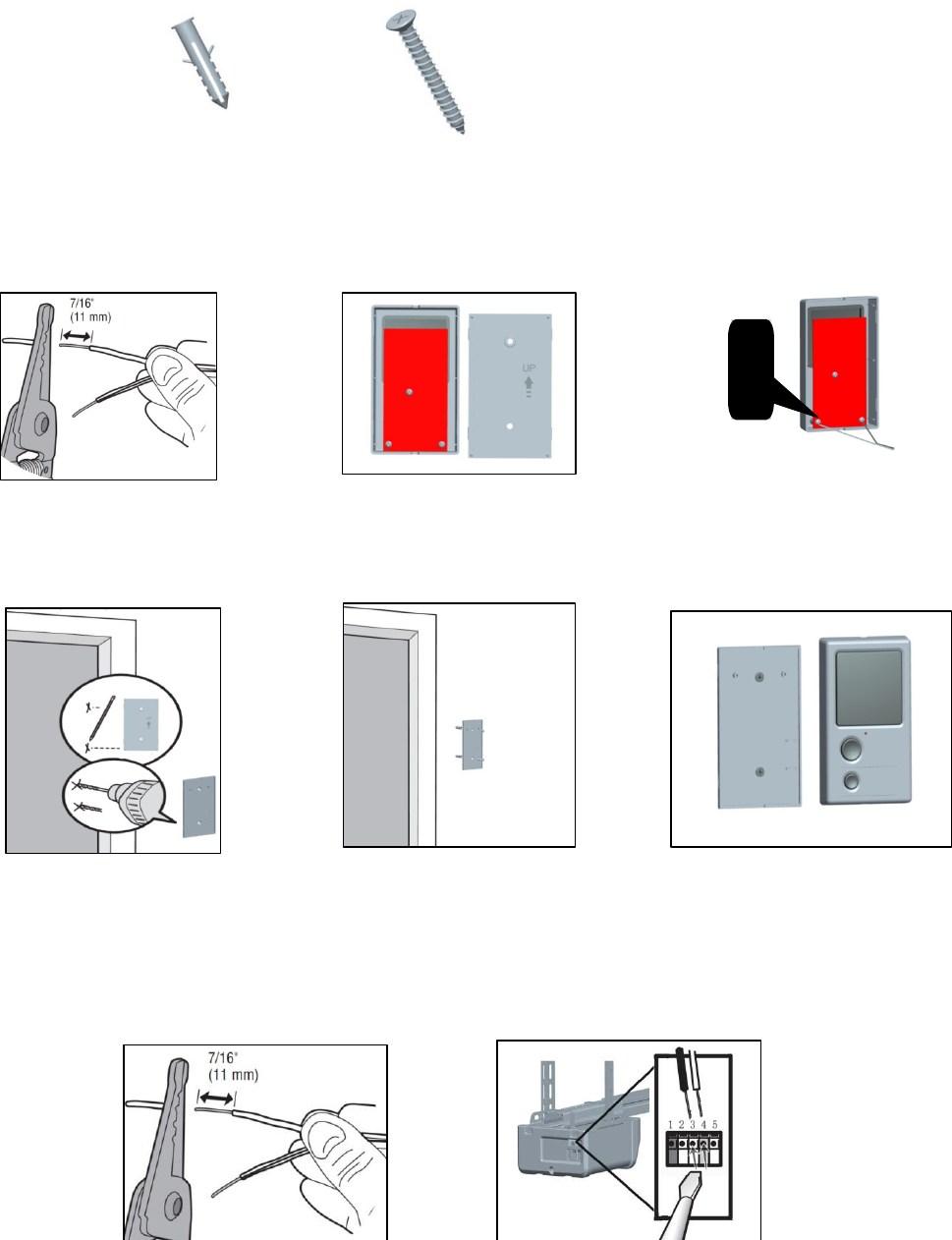
Install the Wall Control
1 Install the wall control
To prevent possible SERIOUS INJURY or DEATH from electrocution:
· Be sure power is NOT connected BEFORE installing door control.
· Connect ONLY to 24 VOLT low voltage wires.
To prevent possible SERIOUS INJURY or DEATH from a closing garage door:
· Install door control within sight of garage door, out of reach of children at a minimum height of 5 feet (1.5 m), and
away from ALL moving parts of door.
· NEVER permit children to operate or play with door control push buttons or remote control transmitters.
· Activate door ONLY when it can be seen clearly, is properly adjusted, and there are no
obstructions to door travel.
ALWAYS k
d i i ht til l t l l d NEVER it t th f l i
9.3 Attach the curved door arm to he door
bracket using the clevis pin (H13). Attach
with the ring fastener (H19).
9.4 Bring arm sections together. Find two pairs of
holes that line up and join sections. Select holes as far
apart as possible to increase door arm rigidity and
attach using the bolts (H15), nuts (H20) and lock
washers (H21).
9.5 Pull the emergency release handle toward
the garage door opener until the trolley
release arm is horizontal. The trolley will
re-engage automatically when the garage
door opener is activated.
H5
H2
H5
H2
H4
H3
H4
H3
19
INTRODUCTION
Install the wall control within sight of the door at a minimum height of 5 feet (1.5 m)
where small children cannot reach, and
away
from the moving parts of the door.
Your product may look different than
the illustrations.
HARDWARE
NOTE: For gang box installations it is not necessary to drill holes or install the drywall anchors. Use the existing holes in the
gang box.
2 Wire the wall control to the garage door opener
Drywall Anchors (2) Screw M4×30 (2)
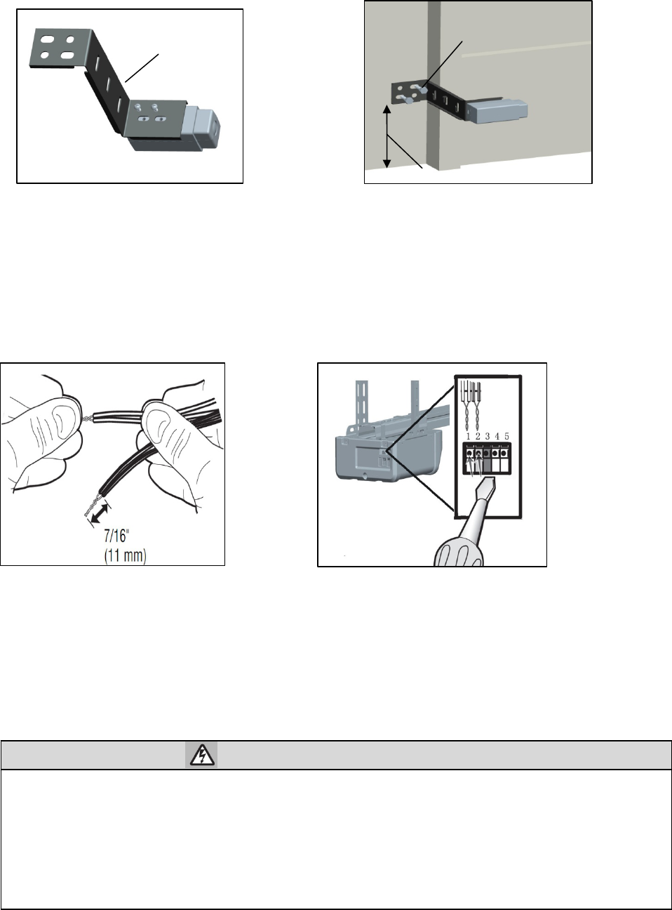
1.1、Strip 7/16 inch (11 mm) of
insulation from one end of the
wire and separate the wires.
1.2、Open the bottom of the wall
control
1.3、Connect the white wire to
the #3 screw ,connect the black
\white wire to the #4 screw .
1.4、Mark the location of the
bottom mounting hole and drill
a 6 mm hole.
1.5、Insert and tighten screws to
secure the bottom of the control to
wall
1.6、Position the wall panel onto
the bottom.
2.1、Strip 7/16 inch (11 mm) of
insulation from one end of the wire and
separate the wires.
2.2、Connect the white wire to the #3
terminal and the black\white wire to the #4
terminal on garage door opener.
20
WARNING
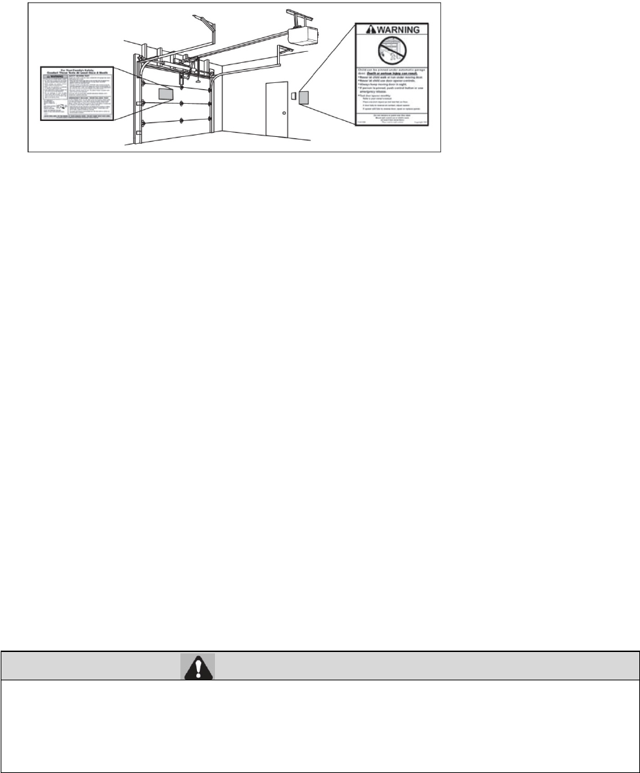
3 Attach the warning labels
3.1 Attach the entrapment warning label on the wall near the door control with tacks or staples.
3.2 Attach the manual release/safety reverse test label in a visible location on the inside of the garage door.
Install The Photo Eye Safety System
Introduction
Be sure power is NOT connected to the garage door opener BEFORE installing the safety reversing sensor.
To prevent SERIOUS INJURY or DEATH from a closing garage door:
· Correctly connect and align the safety reversing sensor. This required safety device MUST NOT be
disabled.
I ll h f i b i NO HIGHER h 6" (15 ) b fl
To insert or remove the wires from
the terminal, push in the tab with a
screwdriver tip.
21
IMPORTANT INFORMATION ABOUT THE SAFETY REVERSING SENSOR
The safety reversing sensor must be connected and aligned correctly before the garage door
opener will move in the down direction.
The sending sensor (with an red LED) transmits an invisible light beam to the receiving sensor (with a green LED). If an
obstruction breaks the light beam while the door is closing, the door will stop and reverse to the full open position, and the
garage door opener lights will flash three minutes
NOTE: For energy efficiency the garage door opener will enter sleep mode when the door is fully closed. The sleep mode shuts
the garage door opener down until activated. The sleep mode is sequenced with the garage door opener light bulb; as the light bulb
turns off the sensor LEDs will turn off and whenever the garage door opener lights turn on the sensor
LEDs will light. The garage
door opener will not go into the sleep mode until the garage door
opener has completed 5 cycles upon power up.
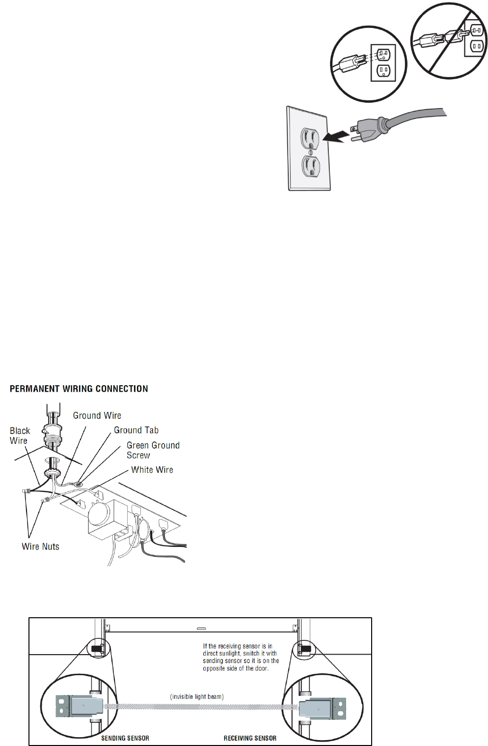
When installing the safety reversing sensors check the following:
· Sensors are installed inside the garage, one on either side of the door.
· Sensors are facing each other with the lenses aligned and the receiving sensor lens does not receive direct sunlight.
· Sensors are no more than 6 inches (15 cm) above the floor and the light beam is unobstructed.
Install The Photo Eye Safety System
1 Install the Safety Reversing Sensors
The safety reversing sensors can be attached to the the wall, The sensors should be no more than 6 inches (15 cm) above the floor.
HARDWARE
Invisible light beam
protection Area
Safety Reversing Sensor
6”(15cm)max.above floor
Screw M4×8(4)
22
WARNING
2 Wire the Safety Reversing Sensors
Power
1 Connect power
To prevent possible SERIOUS INJURY or DEATH from electrocution or fire:
· Be sure power is NOT connected to the opener, and disconnect power to circuit BEFORE removing cover
to establish permanent wiring connection.
· Garage door installation and wiring MUST be in compliance with ALL local electrical and building codes.
· NEVER use an extension cord, 2-wire adapter, or change plug in any way to make it fit outlet. Be sure the
opener is grounded.
1.1 Install the sensors to the mounting
bracket using the screws.
1.2 Position the mounting
b
racket against the wall
with the curved arms facing the door. Make sure
there is enough clearance for the beam to be
unobstructed. Attach the mounting bracket to the
wall using lag screws.
Mounting Bracket Not provided
No more than 15cm
2.1 Strip 7/16 inch (11 mm) of insulation from
each set of wires. Separate the wires. Twist the
white wires together. Twist the white/black wires
together.
2.2 Insert the white wires into the
#1 terminal on the garage door
opener. Insert the white/black wires
into the #2 terminal on the garage door
opener.
23
To avoid installation difficulties, do not activate the garage door opener at this
time. To reduce the risk of electric shock, your garage door opener has a grounding
type plug with a third grounding pin. This plug will only fit into a grounding type
outlet. If the plug doesn’t fit into your outlet, contact a qualified electrician to install the
proper outlet.
THERE ARE TWO OPTIONS FOR CONNECTING POWER:
Option A TYPICAL WIRING
1.1A Plug in the garage door opener into a grounded outlet.
1.2A DO NOT run garage door opener at this time.
Option B PERMANENT WIRING
If permanent wiring is required by your local code, refer to the following procedure.
To make a permanent connection through the 7/8" hole in the top of the motor unit (according to local code):
1.1B Be sure power is NOT connected to the opener, and disconnect power to circuit.
1.2B Remove the garage door opener cover and set aside.
1.3B Remove the attached green ground terminal.
1.4B Cut black and white wires and strip away 1/2" (1 cm) of insulation, 6" (15 cm) before spade terminals.
1.5B Remove the power cord from opener.
1.6B Knock out the hole plugs above 7/8"hole.
1.7B Install a conduit or flex cable adapter to the 7/8" hole
1.8B Run wires through conduit, cut to proper length and strip insulation.
1.9B Attach with wire nuts provided. Attach the ground wire to the green ground screw.
The opener must be grounded.
1.10B Properly secure wire under plastic ties so that wire does not come in contact with moving parts.
1.11B Reinstall the cover. DO NOT run garage door opener at this time.
2 Ensure the Safety Reversing Sensors are aligned
The door will not close if the sensors have not been installed and aligned correctly
When the light beam is obstructed or misaligned while the door is closing, the door will reverse and the garage door
opener lights will flash three minutes. If the door is already open, it will not close.
RED
G
REE
N
LED
24
WARNING
CAUTION
Adjustments
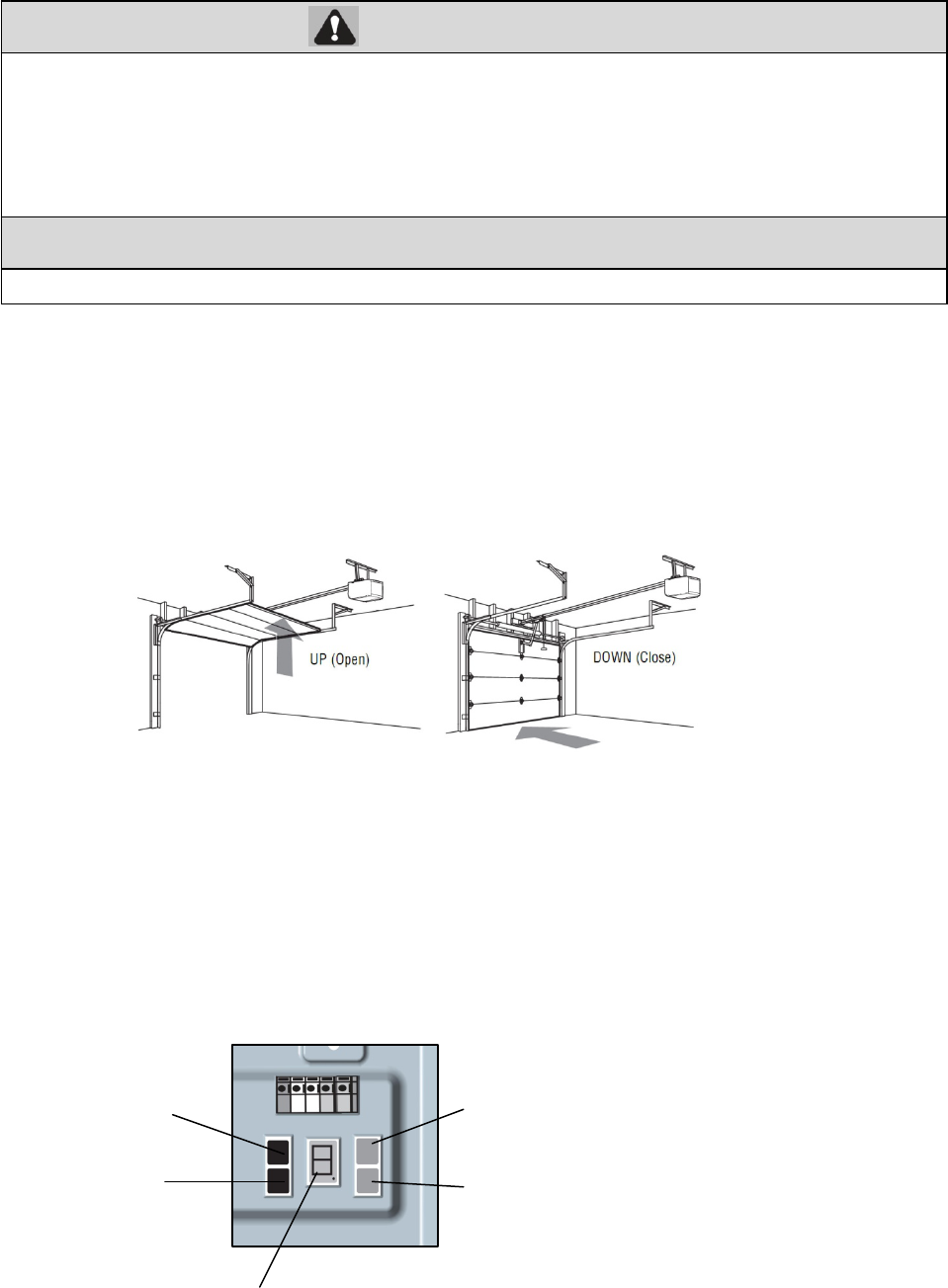
NOTE: If anything interferes with the door’s upward travel it will stop. If anything interferes with the door’s downward travel, it
will reverse.
INTRODUCTION
Your garage door opener is designed with electronic controls to make setup and adjustments easy. The adjustments allow you to
program where the door will stop in the open (UP) and close (DOWN) position. The electronic controls sense the amount of
force required to open and close the door. The force is adjusted automatically when you program the travel and cannot be
changed.
PROGRAMMING BUTTONS
T
he programming buttons are located on the left side panel of the garage door opener and are used to program the travel.
Without a properly installed safety reversal system, persons (particularly small children) could be SERIOUSLY
INJURED or KILLED by a closing garage door.
· Incorrect adjustment of garage door travel limits will interfere with proper operation of safety reversal system.
· After ANY adjustments are made, the safety reversal system MUST be tested. Door MUST reverse on contact
with 1-1/2"
(
3.8 cm
)
hi
g
h
T
o prevent
d
amage to ve
hi
c
l
es,
b
e sure
f
u
ll
y open
d
oor prov
id
es a
d
equate c
l
earance.
PROGRAMMING
BUTTONS
SETTING
BUTTOM
CODE
BUTTOM
+ (UP BUTTOM)
_ (DOWN BUTTOM)
25
WARNING
Adjustments
1 Program the Travel
Without a properly installed safety reversal system, persons (particularly small children) could be
SERIOUSLY INJURED or KILLED by a closing garage door.
· Incorrect adjustment of garage door travel limits will interfere with proper operation of safety reversal
system.
· After ANY adjustments are made, the safety reversal system MUST be tested. Door MUST reverse on
contact with 1-1/2" (3.8 cm) high object (or 2x4 laid flat) on floor.
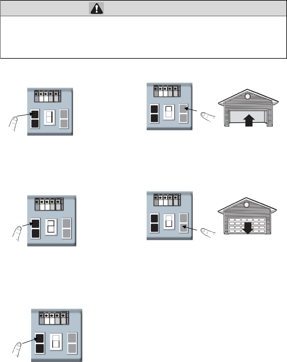
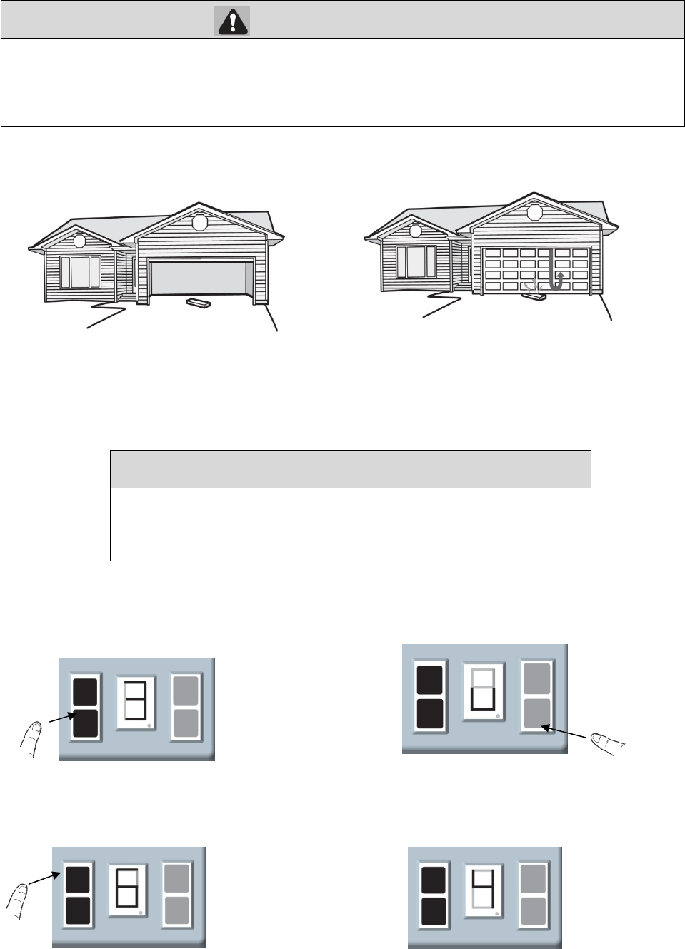
1.1 Press and hold the SETTING
Button until the screen show “1”.
1.2 Press and hold the UP Button until
the door in the desired UP position.
1.3 Once the door in the desired UP position
press and release the SETTING Button. The
screen will show “2”.
NOTE: The UP and DOWN Buttons can be
used to move the door up and down as needed.
1.4 Press and hold the DOWN Button until
the door in the desired DOWN position.
NOTE: The UP and DOWN Buttons can be
used to move the door up and down as needed.
1.5 Once the door is in the desired DOWN
position ,press and release the SETTING
Button. The screen is flashin
g
“||”.
THE
26
WARNING
CAUTION
1.6 The garage door opener will automatically open the door again,then close the door .
2 Test the Safety Reversal System
3 ADVANCED SETTINGS
Option A The “OPEN” position force sensitivity
Wi
t
h
out a proper
l
y
i
nsta
ll
e
d
sa
f
ety reversa
l
system, persons
(
part
i
cu
l
ar
l
y sma
ll
c
hild
ren
)
cou
ld
b
e
SERIOUSLY
INJURED or KILLED by a closing garage door.
· Safety reversal system MUST be tested every month.
· After ANY adjustments are made, the safety reversal system MUST be tested. Door MUST reverse on contact
with 1-1/2" high (3.8 cm) object (or 2x4 laid flat) on the floor.
2.1With the door fully open, place a 1-1/2 inch (3.8 cm)
board (or a 2x4 laid flat) on the floor, centered under the
garage door.
2.2 Press the remote control push button to close the door.
The door MUST reverse when it makes contact with the
board.
If the door stops and does not reverse on the obstruction, the travel needs to be adjusted (refer to Adjustment Step
3). Repeat the test. When the door reverses upon contact with the 1-1/2 inch board, remove the board and open/close
the door 3 or 4 times to test the adjustment. If the test continues to fail, call a trained door systems technician.
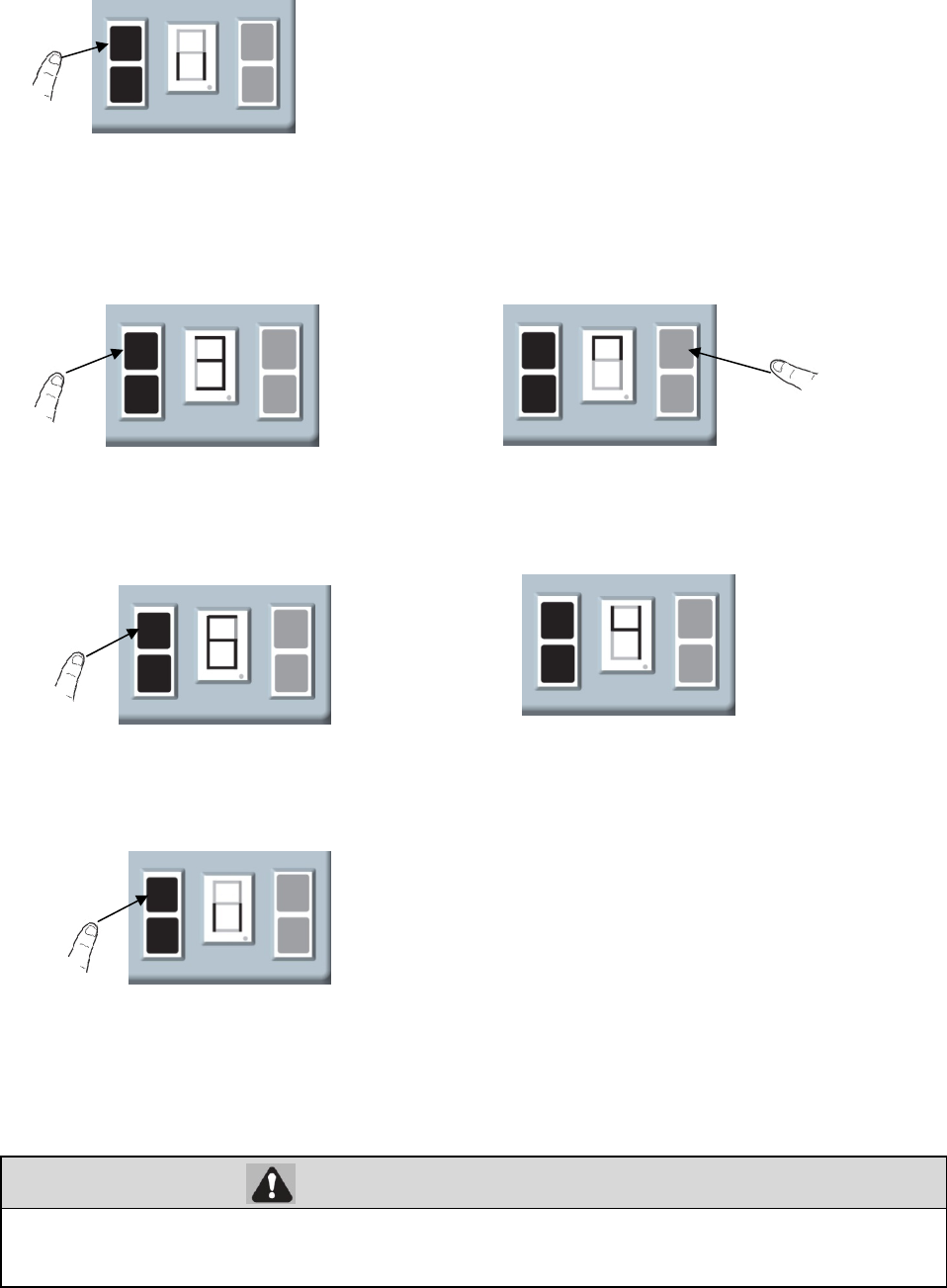
3.1A Press and hold the SETTING Button
until the screen show the number from
“1” to “3”.
3.2 Press and release the DOWN Button
and the screen show the “ ∪”.
3.3A Press and release the SETTING Button and
the screen show the levels of the force
sensitivity.
3.4 Use the UP Bottom to increase the levels, press the
DOWN Bottom decrease the levels . The screen show
the number of the levels.
3.5A Press and release the SETTING Button and
the screen is flashing “||”. Adjustments is
Additional operator functions can be set using the advanced operator
fuctions.Parameters factory default settings can be restored .This programming
ma
y
onl
y
be carried out b
y
a
p
rofessional installer.
27
WARNING
Option B The “CLOSE” position force sensitivity
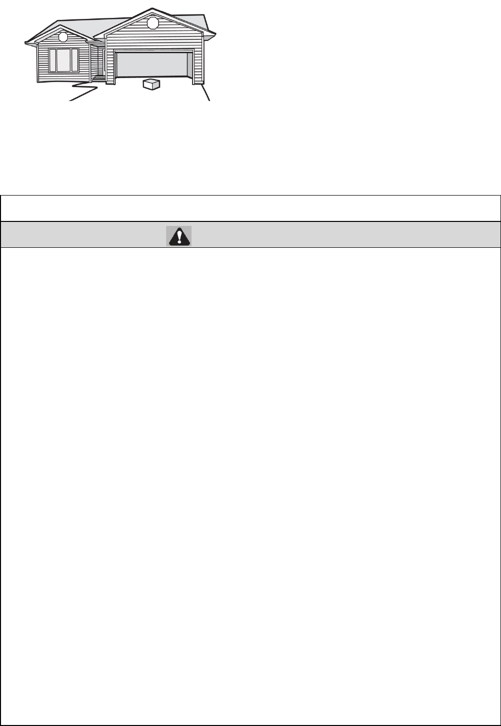
4 Test The Photo Eye Safety System
Without a properly installed safety reversing sensor, persons (particularly small children) could be
SERIOUSLY INJURED or KILLED by a closing garage door.
4.1 Open the door. Place the garage door opener
carton in the
p
ath of the door.
4.2 Press the remote control push button to close the door.
The door will not move more than an inch (2.5 cm), and the
garage door opener lights will flash 10 times.
3.1B Press and hold the SETTING Button
until the screen show the number from
“1” to “3”.
3.2B Press and release the UP Button and the
screen show the “∩”
3.3B Press and release the SETTING Button and
the screen show the levels of the force
sensitivity.
3.4B Use the UP Bottom to increase the levels, press the
DOWN Bottom decrease the levels . The screen
show the number of the levels.
3.5B Press and release the SETTING Button and the
screen is flashing “||”. Adjustments is complete.
28
IMPORTANT SAFETY INSTRUCTIONS
WARNING
To reduce the risk of SEVERE INJURY or DEATH:
1. READ AND FOLLOW ALL WARNINGS AND INSTRUCTIONS.
2. ALWAYS keep remote controls out of reach of children. NEVER permit children to operate
or play with garage door control push buttons or remote controls
3. ONLY activate garage door when it can be seen clearly, it is properly adjusted, and there are
no obstructions to door travel.
4. ALWAYS keep garage door in sight until completely closed. NO ONE SHOULD CROSS
THE PATH OF THE MOVING DOOR.
5. NO ONE SHOULD GO UNDER A STOPPED, PARTIALLY OPENED DOOR
6. If possible, use emergency release handle to disengage trolley ONLY when garage
door is
CLOSED. Weak or broken springs or unbalanced door could result in an open door falling
rapidly and/or unexpectedly.
7. NEVER use emergency release handle unless garage doorway is clear of persons
and
obstructions.
8. NEVER use handle to pull garage door open or closed. If rope knot becomes untied,
you could
fall.
9. After ANY adjustments are made, the safety reversal system MUST be tested.
10. Safety reversal system MUST be tested every month. Garage door MUST reverse on
contact with 1-1/2" high (3.8 cm) object (or a 2x4 laid flat) on the floor.
11. ALWAYS KEEP GARAGE DOOR PROPERLY BALANCED (see page 2). An improperly
balanced door may NOT reverse when required and could result in SEVERE INJURY or
DEATH.
12. ALL repairs to cables, spring assemblies and other hardware, ALL of which are under
EXTREME tension, MUST be made by a trained door systems technician.
13. ALWAYS disconnect electric power to garage door opener BEFORE making ANY repairs
or removing covers.
14. This operator system is equipped with an unattended operation feature. The door
could move unexpectedly. NO ONE SHOULD CROSS THE PATH OF THE MOVING
DOOR.
Note :If the garage door opener closes the door when the safety reversing sensor is obstructed,call for a trained door
systems technician.
Operation
29
WALL Control
Using The Wall Control
Remote Control
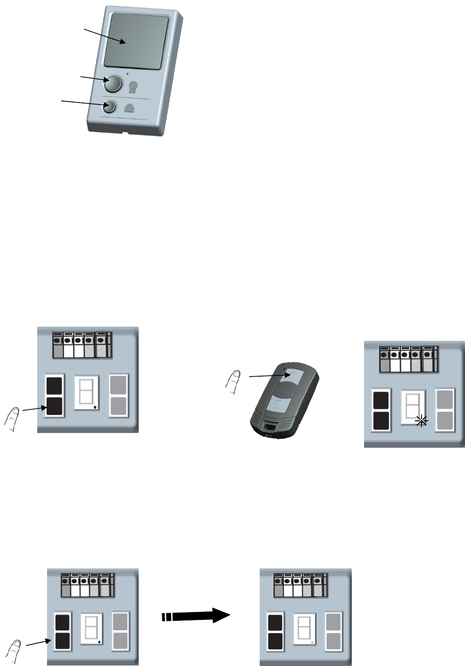
PROGRAM A REMOTE USING THE CODE BUTTON
To Erase the Memory
ERASE ALL REMOTE CONTROLS
1 Press the CODE Button until the screen
shows “●”.
2 Within 10 seconds,press the button on the remote
control , the “●”will turn off. Press the button again, the
“●” will flash and turn off. Now, congratulation!
Press and hold the CODE button on garage door opener, the “●” will
turn on. Release the CODE button when the “●” turns off. All remote
control are now erased. Re
p
ro
g
ram an
y
accessor
y
y
ou wish to use.
Push Ba
r
Light button
Lock
PUSH BA
R
Press the
p
ush
b
ar to o
p
en or close the doo
r
.
LIGHT BUTTON
Press the Light button to turn the garage door opener lights on
or off. When the lights are turned on they will stay on until the
Light button is pressed again, or until the garage door
opener is activated. Once the garage door opener is activated the
lights will turn off after the 3 minutes. The Light button will not
control the lights when the door is in motion.
LOCK
The LOCK feature is designed to prevent activation of the
garage door opener from remote controls while still allowing
activation from the door control .This feature is
useful for added peace of mind when the home is empty .
Activate :press and hold the lock bottom until the LED is
flashing.The lock feature is activated and the your handheld
remote control will not operate your door at this time.
Deactiveate: press and hold the lock bottom again ,the LED
will stop flashing and normal operation will resume.
30
WARNING
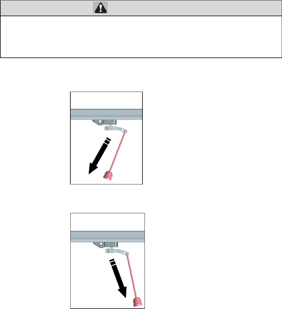
To Open the Door Manually
DISCONNECT THE TROLLEY
1 The door should be fully closed if possible.
2 Pull the emergency release handle toward the door at approximately 45 degrees. The door can now be raised and lowered as
often as necessary.
RECONNECT THE TROLLEY
Pull the emergency release handle toward the garage door opener,the trolley will re-engage the chain connector.
The trolley will reconnect on the next UP or DOWN operation, either manually or by using the door control or remote control.
Maintenance
Maintenance Schedule
EVERY MONTH
· Manually operate door. If it is unbalanced or binding, call a trained door systems technician.
· Check to be sure door opens and closes fully. Adjust if necessary (refer to Adjustment section).
· Repeat the safety reverse test. Make any necessary adjustments (refer to Adjustment section).
EVERY YEAR
To prevent possible SERIOUS INJURY or DEATH
from a falling garage door:
· If possible, use emergency release handle to disengage trolley ONLY when garage door is CLOSED. Weak or
broken springs or unbalanced door could result in an open door falling rapidly and/or unexpectedly.
· NEVER use emergency release handle unless garage doorway is clear of persons and obstructions.
· NEVER use handle to pull door open or closed. If rope knot becomes untied, you could fall.
31
· Oil door rollers, bearings and hinges. The garage door opener does not require additional
lubrication. Do not
grease the door tracks.
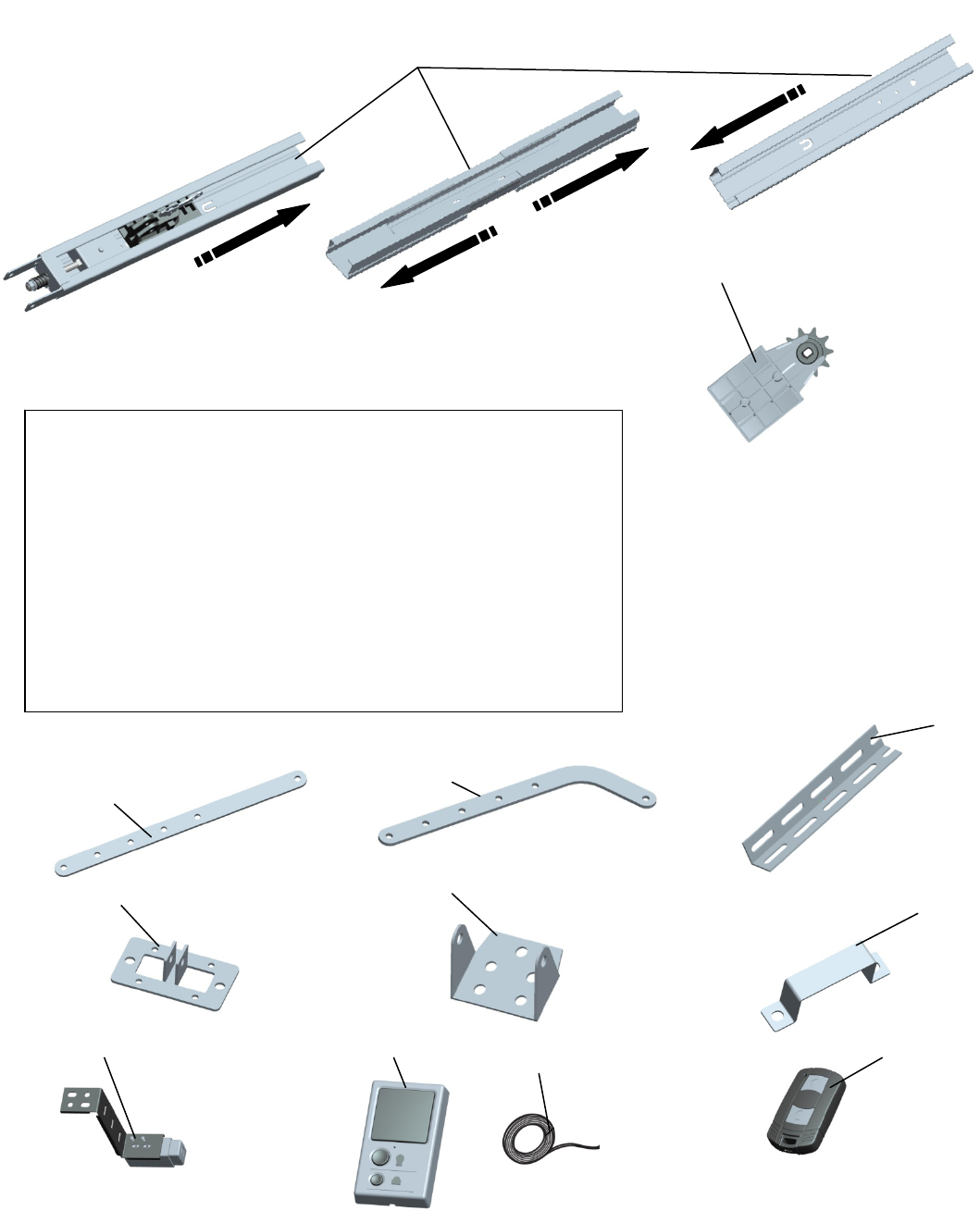
Repair Parts
Rail Assembly Parts
Installation Parts and Accessories
1
2 Sprocket and sprocket holder assembly
1. Straight door arm
2. Curved door arm
3. Hanging bracket
4. Door bracket
5. Header bracket
6. “U” rail clip
7. Mounting Bracket and the safety reversing sensors with 9m wire
8. The wall control
9. Wire
10. Remote control
1 2
3
4 56
7 8
910
32
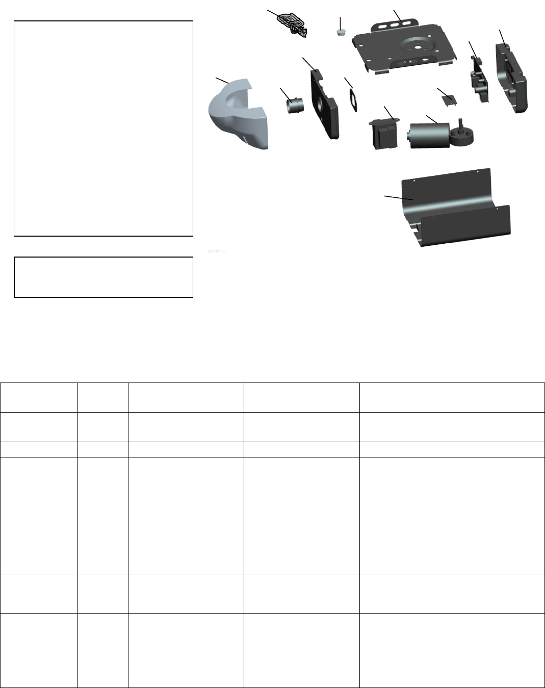
Garage Door Opener Parts
DESCRIPTION
NOT SHOWN
Troubleshooting
Diagnostic Chart
DIAGNOST
IC CODE
T
HE
LIGH
T SYMPTOM CAUSE RESOLUTION
2 flash The opener do not
automatically open the
door and close the door
Manually open and close the door. Check
for binding or obstructions, reprogram the
travel, refer to
p
a
g
e 30.
3 flash The opener do not runs Bad logic control board Replace the logic control board.
4 flash
The garage door opener
will not close and the
light(s) flash.
Safety sensors are not
installed,connected,or
Wires may be cut.
Inspect sensor wires for a disconnected or
cut wire(s). If the sending sensor
with the RED LED is NOT lit, check the
wire and connections for that sensor.
If sending sensor LED is lit, check the
wire connections leading to the receiving
sensor (green LED). Reattach wire or
replace wire as needed. If
pre-wired home, check the splices. See
page 24 for installation. Close the garage
door using the remote control or the door
control.
5 flash
Door is closing,stops
and reverses Obstruction,binding or
sticking door
If your door is binding or sticking, contact
a trained door systems technician。If
your door is okay, reprogram the travel,
refer to
p
a
g
e 28.
6 flash
The openers runs
approximately 8-12mm
and stops
Communication error
to travel module
Disconnect all power, remove cover, and
locate the travel module. Ensure the wires
for travel module are connected, if wires
are connected, then replace the travel
module.
1. Chassis.
2. Motor and Hall sensor
3. Transformer
4. Logic Control Board
5.Light Lens(Model 9357·Model9367)
6.Light Socket
7. Light socket fixed board
8. End panel with light socket
9. End panel with Logic Control Board
10. Cover (Model 9357·Model9367)
11.Wiring Board
12.Strain relief
13.Power Cord
1
Wire Harness Kit
Hall sensor
2
3
4
5 67
8
9
10
11
12
13
FCC STATEMENT :
This device complies with Part 15 of the FCC Rules. Operation is subject to the following
two conditions:
(1) This device may not cause harmful interference, and
(2) This device must accept any interference received, including interference that may
cause undesired operation.
Warning: Changes or modifications not expressly approved by the party responsible for
compliance could void the user's authority to operate the equipment.
NOTE: This equipment has been tested and found to comply with the limits for a Class B
digital device, pursuant to Part 15 of the FCC Rules. These limits are designed to provide
reasonable protection against harmful interference in a residential installation.
This equipment generates uses and can radiate radio frequency energy and, if not
installed and used in accordance with the instructions, may cause harmful interference to
radio communications. However, there is no guarantee that interference will not occur in a
particular installation. If this equipment does cause harmful interference to radio or
television reception, which can be determined by turning the equipment off and on, the
user is encouraged to try to correct the interference by one or more of the following
measures:
Reorient or relocate the receiving an tenna.
Increase the separation between the equipment and receiver.
Connect the equipment into an outlet on a circuit different from that to which the
receiver is connected.
Consult the dealer or an experienced radio/TV technician for help.
RF warning statement:
The device has been evaluated to meet general RF exposure requirement. The device
can be used in portable exposure condition without restriction.