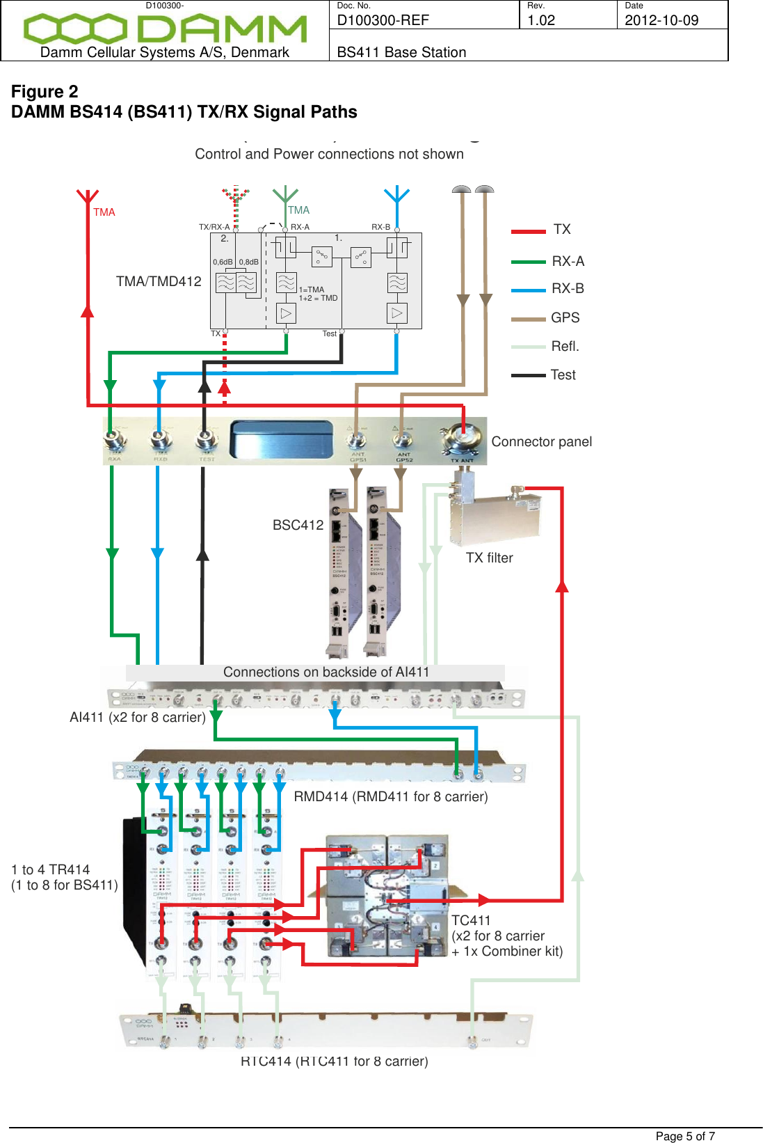
Damm Cellular Systems A S 104013 Door System Transmitter User Manual Description

Damm Cellular Systems A/S Door System Transmitter Description

User addendum 8 carrier 11 01 2012

D100300- Doc. No. Rev. Date D100300-REF 1.02 2012-10-09  Damm Cellular Systems A/S, Denmark BS411 Base Station   Page 1 of 7                              1.1 BS411 BASE STATION - 8 CARRIER   Description DAMM BS411 is a 8-carrier TETRA indoor base station and is complementary to DAMM BS421 and DAMM BS414 TETRA base stations. The BS411 may be used in networks where high traffic capacity is required (up to 31 Erlang).   It is designed for a fully IP based connectivity and allows for remote supervision and diagnostic, test, control, setting and software update, file transfer and SNMP. Its embedded Operate & Maintenance (OM) system is reached by means of Windows desktop.  The BS411 support discontinuous transmission fully GPS synchronized. This allows a dramatic decrease in power consumption, as only the active TR412 (‘s) needs to be powered, until traffic load requires more carriers to be on air.   BS411 fully supports Voice + Data services in full and half duplex modes, compliant with the ETSI EN 300 392   Access to all field replaceable units (FRU) is from the front, protected by a lockable door, and all external connectors in located on top of the rack.
D100300- Doc. No. Rev. Date D100300-REF 1.02 2012-10-09  Damm Cellular Systems A/S, Denmark BS411 Base Station   Page 2 of 7 The BS411 consist of the base station controller, the transceiver modules, the combiner system and the filter system. In the receiver path a separate Tower Mounted Amplifier/Duplexer (TMD412) is an integrated functional part of BS411.   The TMD412 is intended for mast/tower mounting. Substantially the unit is a receiver amplifier, but can be coupled as an amplifier with build in duplex filter. Using the TMD412 in Duplex mode needs to take into consideration the numbers of carriers and frequencies used, in order to eliminate potential interference.   The TMD412 amplification of the received signals fully eliminates the feeder cable loss by up to 8dBm, which gives superior radio coverage performance and link balance.  The BS411 rack contains (ref. to figure 1 and 2 on page 4-5):  Base Station Controller, BSC412. The operating system in the BSC412 executes DAMM’s TetraFlex® system software and may as well execute Tetra system software from DAMM OEM Partner. By installing a second redundant BCS412 in the BS411 rack, reliability will be improved.  BSC412 is equipped with an internal GPS receiver giving accurate time, date and frequency synchronization of all installed TR412’s and to allow the base station to run full time synchronous with other base stations in a network. This is necessary for optimum cell-reselection and seamless handover from mobiles. Missing GPS signals will cause the internal high stability oscillator to take over synchronization. The GPS sync input signal from a single GPS antenna may as well allow for external synchronization in tunnels solutions and in other operational areas where GPS signals cannot be received directly. It is provided with an enhanced processer with the ability to handle a complete TETRA site. It contains enhanced Ethernet LAN and WAN connections intended for Voice over IP switching. Dongle management of software licenses can be provided via an USB port.   Power Supply, PS411. The PS411 is connected to mains, 100 to 240VAC 47-63Hz, or -48V batteries and supply all units in the rack and the TMD412 and beside offers -48VDC for auxiliary units and/or the ability to charge an external battery, controlled by the External Battery Kit. The power supply cassette has space for the necessary numbers of PS411 to supply the fully equipped rack plus one more for N+1 redundancy.  All Power supplies have load sharing to improve reliability. A built-in micro-controller in the PS411 allows close monitoring of all main parameters both via the O&M interface and from the network management system. Configuration can be stored directly in the PS411, but will normally be controlled of common configurations in the BSC411 Base Station Controller.
D100300- Doc. No. Rev. Date D100300-REF 1.02 2012-10-09  Damm Cellular Systems A/S, Denmark BS411 Base Station   Page 3 of 7 Transceiver, TR412 The TR412 Transceiver is a complete TETRA carrier unit The TX section contains a linear, low noise transmitter linearized with a Cartesian loop. It can deliver a peak output power of 60W, giving a nominal output power of 25W TETRA . Modulation and power control is performed in software of the DSP. The output amplifier is protected with a VSWR protection circuit and a temperature protection scheme. The forward and reflected power can be measured with built-in RMS power meters. An RFTL output is available for Base Station test. The RX is a double super-heterodyne high dynamic range receiver provided with dual diversity with separate RX paths all the way to the DSP. The final selectivity, diversity combination, demodulation etc. is made in DSP software.  The 16-bit micro-controller handles the general control functions of the transceiver, boot of DSP, O&M communications etc. It also handles the packet mode communication on the HDLC bus to the BSC412.  All internal frequencies are generated with PLL’s locked to the information coming from the BSC.   TX Combiner, TC411. The TC411 is a 4-way TX cavity combiner module used to combine the individual TX outputs to a single cable.  The TC411 consists of 4 motor-tuned ¼ or ¾ λ TEM resonators. The inputs are provided with dual circulators with high-power loads, which are able to dissipate the reflected power when the TX antenna is missing or the cavity is tuned to a frequency not matching the transmitter. An RF detector is provided on the high-power load used for manual adjustment and alarm generation. The TC411 is equipped with the TCC411 TC Combiner Controller with built-in micro-controller, which controls the motors.  At power-up, the micro-controller initializes the tuning position against a mechanical end stop. The TCC411 is connected to the O&M UART bus and can be reached with O&M commands from the BSC412.  TX Filter, TF411. The TF411 is a high power TX filter, which reduces the radiation in the RX band, and is connected to the TX antenna socket located on top of rack.  Tower Mounted Amplifier/Duplexer, TMD412. The TMD412 contains two low-loss highly selective RX filters and two low-noise high dynamic range amplifiers which amplify the RXA and RXB signals. The TMD412 also contains a duplex filter, which can be used to combine the TX and one of the RX antennas to a single antenna. The duplex part of the TMD412 is optimized for low loss and extremely low inter-modulation distortion. When using the duplex filter option, care shall be taken not to use TX frequencies generating 5 th  order inter-modulations products in the RX frequencies
D100300- Doc. No. Rev. Date D100300-REF 1.02 2012-10-09  Damm Cellular Systems A/S, Denmark BS411 Base Station   Page 4 of 7 Antenna Interface, AI411. The AI411 Antenna Interface unit is used in all Base Station (BS411and BS414) and contains all the necessary circuit to support a complete Radio Cell including support of the Tower Mounted Amplifier/Duplexer TMD412 with all functions. The two independent RX multi-coupler amplifiers are built with low-noise high dynamic range transistors. They have DC-insertion in the feeders for the TMA/TMD and alarm circuits to monitor the TMA/TMD’s and the internal amplifiers´ current consumption. Included in the input are variable input attenuators to adjust for actual cable loss.  An RF Power Detector is used to supervise the forward and reflected power at the TX antenna connector. The detectors are temperature-compensated and the output levels can be fine adjusted.   Receiver Multi-coupler Divider, RMD411. The RMD411 divides the RXA and RXB signals and feed them to the receiver part of the TR412  Figure 1  DAMM BS411 with text    Connection Box CON Antenna Interface AI Receiver Multicoupler Divider        RMD Base Station controller BSC Carrier units TR Radio Frequency Test Loop combiner RFTL Power Supply units PS Blower module 4-channel Transmitter Cavity combiners TC
D100300- Doc. No. Rev. Date D100300-REF 1.02 2012-10-09  Damm Cellular Systems A/S, Denmark BS411 Base Station   Page 5 of 7 Figure 2 DAMM BS414 (BS411) TX/RX Signal Paths  TXRX-BGPSRefl.TestBSC412TMA/TMD412TX filterRMD414 (RMD411 for 8 carrier)RTC414 (RTC411 for 8 carrier)Connector panelRX-ARX-BRX-ATestTX1.2.1=TMA1+2 = TMDTX/RX-AAI411 (x2 for 8 carrier)TC411(x2 for 8 carrier + 1x Combiner kit)DAMM BS414 (BS411) TX/RX Signal PathControl and Power connections not shown1 to 4 TR414(1 to 8 for BS411)Connections on backside of AI411TMATMA0,6dB   0,8dB
D100300- Doc. No. Rev. Date D100300-REF 1.02 2012-10-09  Damm Cellular Systems A/S, Denmark BS411 Base Station   Page 6 of 7 Specification Parameter Value Frequency Bands:  RX=300-310MHz, TX=336-346MHz, BW=10MHz  RX=350-360MHz, TX=360-370MHz, BW=5MHz  RX=380-390MHz, TX=390-400MHz, BW=5MHz EU Public safety RX=410-420MHz, TX=420-430MHz, BW=5MHz  RX=450-460MHz, TX=460-470MHz, BW=5MHz  RX=805-825MHz, TX=850-870MHz, BW=14MHz US-FCC Other frequencies on request    Common TX/RX:  Synthesizer frequency step 12,5kHz Frequency accuracy Locked to GPS Timing accuracy +/-14us ref. GPS timing   Duplexer- Amplifier:  RX feeder loss compensation max. 8 dB nom. TX path insertion loss (10MHz duplex spacing) 0.6dB typ.   Transmitter;  Output power before combiner 1 to 25W  Output power after cavity combiner and TX filter ½ to 10W  TX linearization scheme Cartesian Loop Forward and reflected power meter 0.1W to 99.9W   Receiver:  Note: The TMD412 Tower Mounted Amplifier/Duplexer is a functional an integral part of BS41x range. The two RX amplifiers in the TMA/TMD are included in the RX sensitivity values.   Diversity Dual as standard RX sensitivity with diversity. Static -121dBm RX sensitivity without diversity. Static -117dBm RX sensitivity with diversity. Dynamic TU50 at 4% BER -118dBm RX sensitivity without diversity. Dynamic TU50 at 4% BER -112dBm Noise figure 3.5dB typ. 3rd –order IM input intercept point +13dBm typ. Intermediate frequencies 45MHz and 144kHz RSSI dynamic range Noise floor to -43dBm   Base Station Control Unit  Operating system:  Host processor Pentium M 1,4GHz RAM 1GByte Operating system Windows WES2009 Synchronisation of date/time  From GPS or External sync. Non synchronized operation Built-in oscillator Co-processor HDLC buses to TR412 and PS411 CF Disk Multiple partition 8GB (2GB+2GB+4GB) Optional CF Disk Multiple partition 16GB (2GB+2GB+12GB) Ethernet including voice over IP 10/100Mbit Synchronization 1 sec pulse in/out Antenna configuration:  Using TMD412 coupled as duplexer, no diversity One combined TX/RX Using TMD412 coupled as duplexer, dual diversity One TX/RX A, One RX B Using TMD412 coupled as amplifier, dual diversity One TX, One RX A, One RX B GPS antenna Passive or Active (+5V DC)
D100300- Doc. No. Rev. Date D100300-REF 1.02 2012-10-09  Damm Cellular Systems A/S, Denmark BS411 Base Station   Page 7 of 7  Note:  The Base Station is shipped to the end-customer having been fully assembled and tested at the factory in its final configuration.  No other assembly is needed in the field except installing, connection to external components, power and lan / wan. Damm checks each system that leaves the factory to secure that the system parameters meets all FCC and CE requirements for output power and spurious emission. Installers are reminded to exercise great care in connecting the system to external RF component and to check output power and spurious emission as for any RF system. Combiner:  4-way cavity combiner, motor tuned Two combiners installed as Standard Channel spacing per cavity combiner >175kHz    Internal connectors between Base Station rack and TMD412:  RXA – RXB and Test N Female TX 7/16   External Connectors:  Directly on BS rack or TMD412:  2 x GPS antenna connector one for each BSC412 BNC on top of Rack Earth Base Station Rear right top of the rack Earth TMD412 Mounting Plate Via Connection Box  AC Mains connector 100 to 240 V AC (Phase, 0, GND)  Screw-type for 6sq. mm. max External DC supply or battery connector -48V DC (-48, 0, GND) Screw-type for 10sq. mm. max  - 48V out for external router/modem etc. (-48, 0, GND) Screw terminal 3 x 2.5#   External battery temperature sensor RJ12 BSC1 and BSC2 Ethernet LAN/WAN connections RJ45 (x8) Number of RJ45 patch-field positions 3 External alarm connector (8xIn/GND and 2xOut/+14V) LSA for 0,4-0,6 mm solid wire External 1 sec. Sync (BSC1 and BSC2) LSA for 0,4-0,6 mm solid wire   Power Supply:  Power source -48V DC or 100-240VAC, 47-63Hz Power consumption basic rack without carriers 50W Power consumption per active carrier at 10W output 100W Power consumption per “standby carrier 14W Power consumption with 8 active carriers at 8 x10W output 850W  Output for external battery, adjustable -52,8 to 55,2VDC – max 14A Output for other units, fixed, (alternative to charging battery) -48VDC - 12A   Physical:  Rack 36U  Dimensions (HxWxD), excl. connectors 1721x542x520 mm Weight, fully equipped 143kg Storage temperature range  -40oC to +85o C Operating temperature range -20o C to +55o C Encapsulation IP20 TMD412:  Dimensions (HxWxD), excl. connectors 337x245x130mm Weight (incl. Mounting accessories) 8.9kg Wind area 0.1sq.m  Storage temperature range -55 to +70 Celsius Operating temperature range -25 to +55 Celsius Optional temperature range -55 to +70 Celsius Encapsulation IP65

Navigation menu