DareGlobal Technologies DB101 ADSL Modem User Manual 392996
Shanghai DareGlobal Technologies Co., Ltd. ADSL Modem 392996
Contents
- 1. users manual1
- 2. users manaul2
users manaul2
DB101
USB ADSL MODEM
USER’S MANUAL
V3.0
DARE TECHNOLOGIES CO., LTD.
http://www.dare-tech.com

DB101 ADSL MODEM Manual
- 1 -
CONTENTS
1. OVERVIEW....................................................................................................................................................... 2
1.1 ABOUT ADSL .............................................................................................................................................. 2
1.2 DEVICE INTRODUCTION.......................................................................................................................... 2
1.3 PROTOCOL AND DRIVER..........................................................................................................................2
1.4 CHARACTERISTICS ................................................................................................................................... 3
2. USB ADSL MODEM INSTALLATION AND SOFTWARE CONFIGURATION ...................................... 4
2.1 SYSTEM REQUIREMENTS. ....................................................................................................................... 4
2.1.1 HARDWARE ........................................................................................................................................ 4
2.1.2 SOFTWARE.......................................................................................................................................... 4
2.2 HARDWARE INSTALLATION....................................................................................................................4
2.2.1 CONNECTION..................................................................................................................................... 4
2.2.2 PROCEDURE. ...................................................................................................................................... 4
2.3 DRIVER INSTALLATION .......................................................................................................................... 5
3. CUSTOMER CONFIGURATION................................................................................................................... 9
4. UNINSTALLATION ....................................................................................................................................... 11
5. CONNECTION SETUP.................................................................................................................................. 13
5.1 PHYSICAL LAYER CONNECTION.......................................................................................................... 13
5.2 DIAL-UP CONNECTION........................................................................................................................... 14
5.3 PRIVATE LINE CONNECTION................................................................................................................. 16
6. PPPOE CONFIGURATION........................................................................................................................... 18
7. SPECIFICATION............................................................................................................................................ 19
7.1 POWER SUPPLY ........................................................................................................................................ 19
7.2 DIMENSION............................................................................................................................................... 19
7.3 WEIGHT...................................................................................................................................................... 19
7.4 CERTIFICATION........................................................................................................................................ 19
7.5 OPERATING ENVIRONMENT ................................................................................................................. 19
APPENDIX A GLOSSARY................................................................................................................................20
APPENDIX B TROUBLESHOOTING............................................................................................................. 22
APPENDIX C SPLITTER CONNECTION...................................................................................................... 23
APPENDIX D SHIPPING LIST ........................................................................................................................ 24
DB101 ADSL MODEM Manual
- 2 -
1. OVERVIEW
1.1 ABOUT ADSL
An ADSL MODEM is a broadband access device, which utilizes the high frequency segment of a phone
line to transmit high-speed data without interfering with the voice transmission. The frequency of the ADSL
signal is higher than that of voice, so the voice and ADSL signal can coexist in one line by using a Splitter to
insulate the two. ADSL data transfer adapts asymmetry model. It has an upstream maximum transmission rate
of 1 Mbps and downstream maximum transmission rates of 8 Mbps. This ability makes ADSL an ideal device
for broadband access.
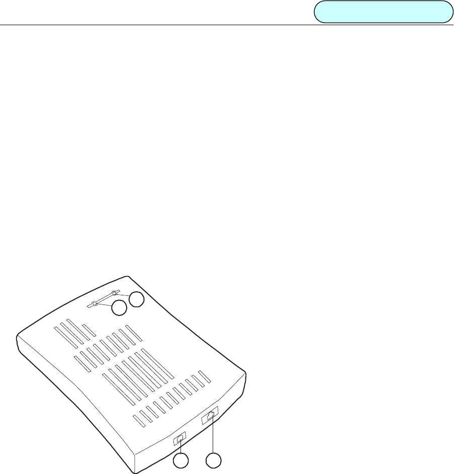
1.2 DEVICE INTRODUCTION
1
2
34
Figure 1
POWER indicator
LINK indicator
USB port
LINE port
1.3 PROTOCOL AND DRIVER
1. PPP over ATM (PPPoA) VCMUX (RFC2364)
2. PPP over ATM (PPPoA) LLC (RFC2364)
3. PPP over Ethernet (PPPoE) LLCSNAP (RFC2516)
4. PPP over Ethernet (PPPoE) VCMUX (RFC2516)

DB101 ADSL MODEM Manual
- 3 -
5. Bridged IP over ATM LLCSNAP (RFC1483)
6. Routed IP over ATM LLCSNAP (RFC1483)
7. Bridged IP over ATM VCMUX (RFC1483)
8. Routed IP over ATM VCMUX (RFC1483)
9. Classical IP over ATM (RFC1577)
Driver Types and OS Supported
Table 1
Driver
Type Protocol OS
LAN RFC 1483
RFC 1577
Windows® Me
Windows® 98
Windows® 98 SE
Windows® 2000
Windows® XP
WAN RFC 2364
RFC 2516
Windows® Me
Windows® 98
Windows® 98 SE
Windows® 2000
Windows® XP
1.4 CHARACTERISTICS
• USB v1.1 Compatible.
• Utilizes USB BUS power; no additional power supply required.
• Supports Hot-plug / Hot-swap
• Supports Plug & Play
• Supports ATM WAN Miniport, NDIS 5.0, and NDIS 4.0 Miniport.
• Supports ANSI T1.413 ISSUE 2 and G.992.1 (G.DMT), G.992.2 (G.LITE).
• Software upgradeable.
• Provides configuration and monitoring programs.
• Upstream maximum transmission rates of 1 Mbps
• Downstream maximum transmission rates of 8 Mbps
• Maximum transmission distance of 5 km.
DB101 ADSL MODEM Manual
- 4 -
2. USB ADSL MODEM INSTALLATION AND SOFTWARE
CONFIGURATION
2.1 SYSTEM REQUIREMENTS
2.1.1 HARDWARE
• Pentium® MMX 233(or higher)
• Minimum of 32MB memory.
• Minimum 10MB free disk space.
• CD-ROM
• USB port
2.1.2 SOFTWARE
• Windows® Me
• Windows® 98
• Windows® 98 SE
• Windows® 2000
• Windows® XP
2.2 HARDWARE INSTALLATION
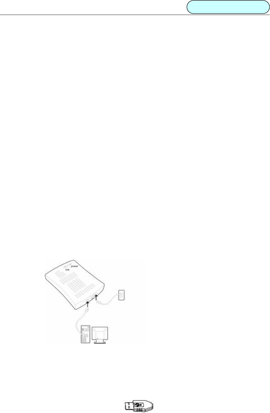
2.2.1 CONNECTION
Figure 2.2.1
2.2.2 PROCEDURES
1. While your computer is On, plug one end of telephone line to the USB ADSL MODEM LINE port as
shown in Figure 1 . Then plug the other end of the telephone line to the telephone socket on the wall.
NOTEIf you use ADSL MODEM and telephone simultaneously, please refer to Appendix C.
2. Plug one end of the USB cable as shown here to an available USB port on your PC.
DB101 ADSL MODEM Manual
- 5 -
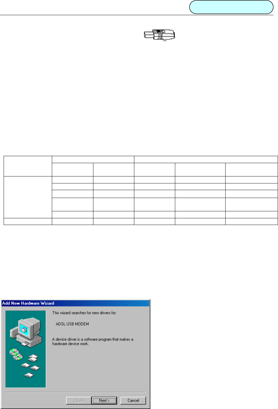
3 Plug the other end of the USB cable as shown here to the ADSL USB port as shown by
interface in Figure 1 Section 1.
After you complete the above steps, your PC will indicate, “Found new hardware and installing
driver”. Please refer to section 2.3 for more details.
2.3 DRIVER INSTALLATION
2.3.1 Microsoft Windows® 98
Confirm the information below before installation. If you have any questions please consult your local
ADSL service provider. The table below shows the information needed for configurations for different
protocols.
Table 2
VIRTUAL DIAL-UP MODE PRIVATE LINE MODE
PROTOCOL PPPoE PPPoA 1483 BRIDGE
CONNECT
1483 ROUTING 1577 PRIVATE
LINE
VPI VPI VPI VPI VPI
VCI VCI VCI VCI VCI
LLC/VCMUX LLC/VCMUX LLC/VCMUX LLC/VCMUX LLC/VCMUX
USER NAME USER NAME IP
ADDRESS/MASK
IP
ADDRESS/MASK
NECESSARY
INFORMATION
PASSWORD PASSWORD GATEWAY GATEWAY
Manual Section 5.2 5.2 5.3 5.3 5.3
Driver under WAN folder is for PPPoE and PPPoA
Driver under LAN folder is for 1483 bridge connecting, 1483 routing and 1577 private line.
NOTEPlease close all running programs before installing the driver. Windows®98 installation CD will
be required for driver installation.
The following shows the steps for WAN driver installation. LAN driver installation is similar to this.
1. Once the new hardware is detected as shown in the dialog box below, Click “Next” button. As shown figure
2.3.1.1.
Figure
2.3.1.1
DB101 ADSL MODEM Manual
- 6 -
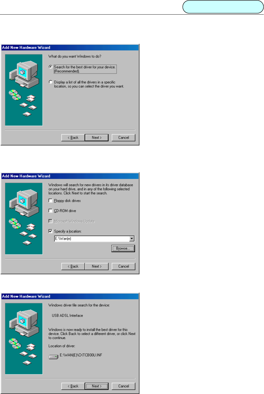
2. A new dialog box will ask which searching method should be chosen. Select default method and click
“Next” button. As shown figure 2.3.1.2.
Figure
2.3.1.2
3. A new box will pop up for selection of the location of the driver. If the location is incorrect please click
“Browse” and select the right location, then click “Next” button. As shown figure 2.3.1.3.
Figure 2.3.1.3
4. A box will appear indicating the driver has been found, click “Next” button. As shown figure 2.3.1. 4
Figure 2.3.1.4
DB101 ADSL MODEM Manual
- 7 -
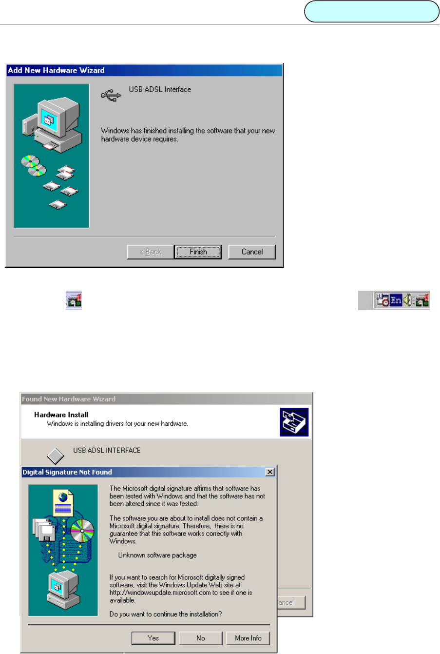
5. A message box will show the installation is complete. Click “Finish” button. As shown figure 2.3.1.5.
Figure 2.3.1.5
6. A new icon will be appear in the taskbar on the lower right corner of the screen.
2.3.2 Microsoft Windows® 2000
NOTE: Please close all running programs before installing the driver. The installation process is similar
with that for Win98, but a digital signature box will appear as shown below.
1. “Digital signature not found” dialog box will appear to indicate the software has no signature, click “Ye s ”
button. As shown figure 2.3.2.1
Figure 2.3.2.1
DB101 ADSL MODEM Manual
- 8 -
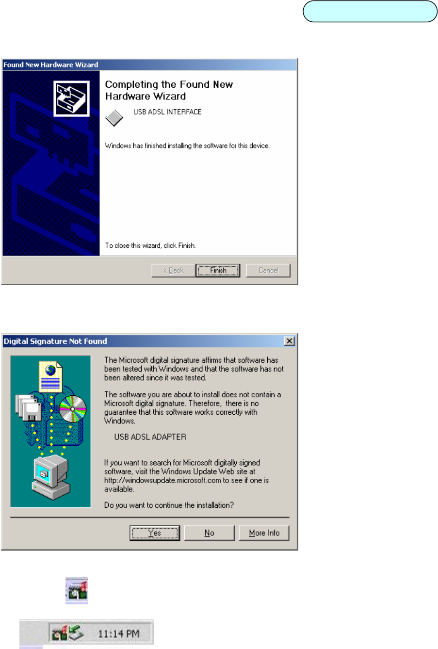
2. A message box will indicate the installation is finished. Click “Finish”.
Figure 2.3.2.2
3. “Digital signature not found” dialog box will appear again, click “Ye s” to continue.
Figure 2.3.2.3
4. A new icon will appear in the taskbar at the lower right corner of the screen.
DB101 ADSL MODEM Manual
- 9 -
3. CUSTOMER CONFIGURATION
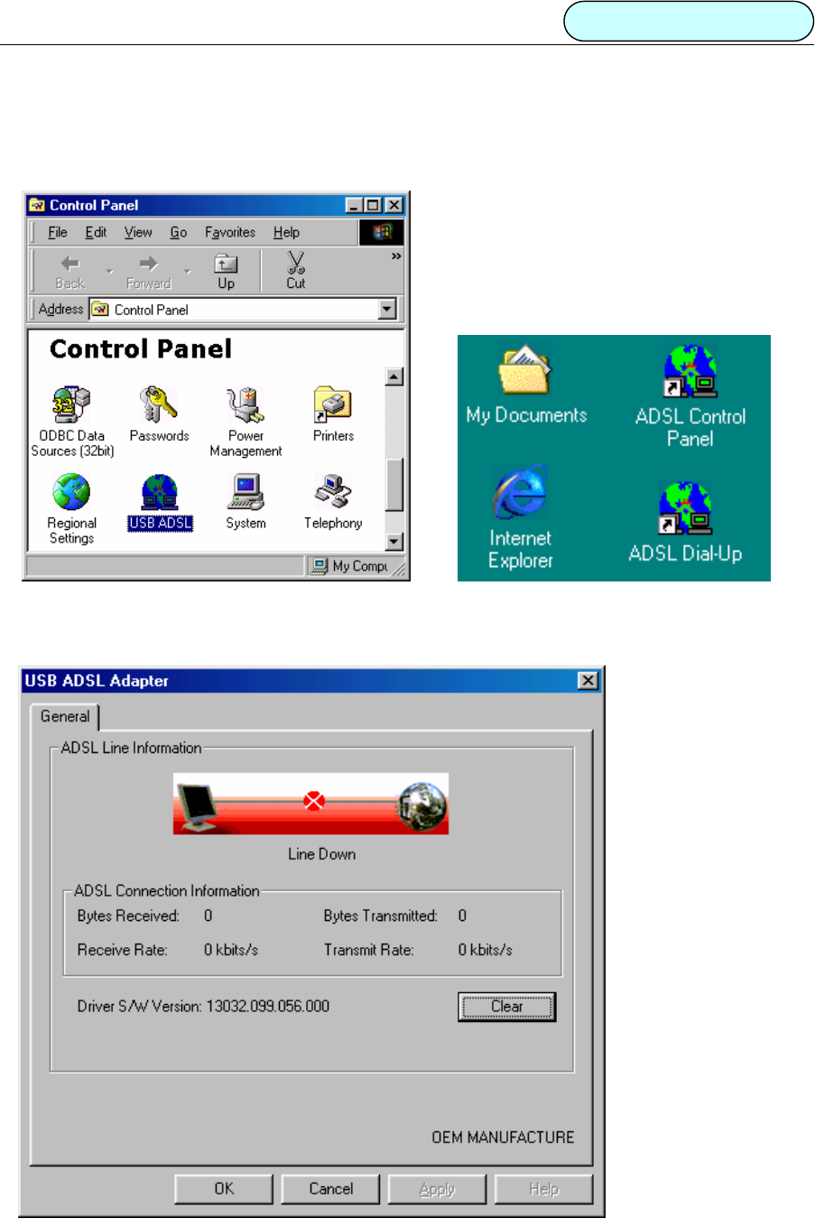
1. Double click “USB ADSL” icon in the Control Panel. As shown figure 3.1
Figure 3.1 Figures 3.2
Or double click “ADSL CONTROL PANEL” icon on the desktop. As shown figure 3.2
2. A dialog box will appear as shown below. As shown figure 3.3
Figure 3.3
DB101 ADSL MODEM Manual
- 10 -
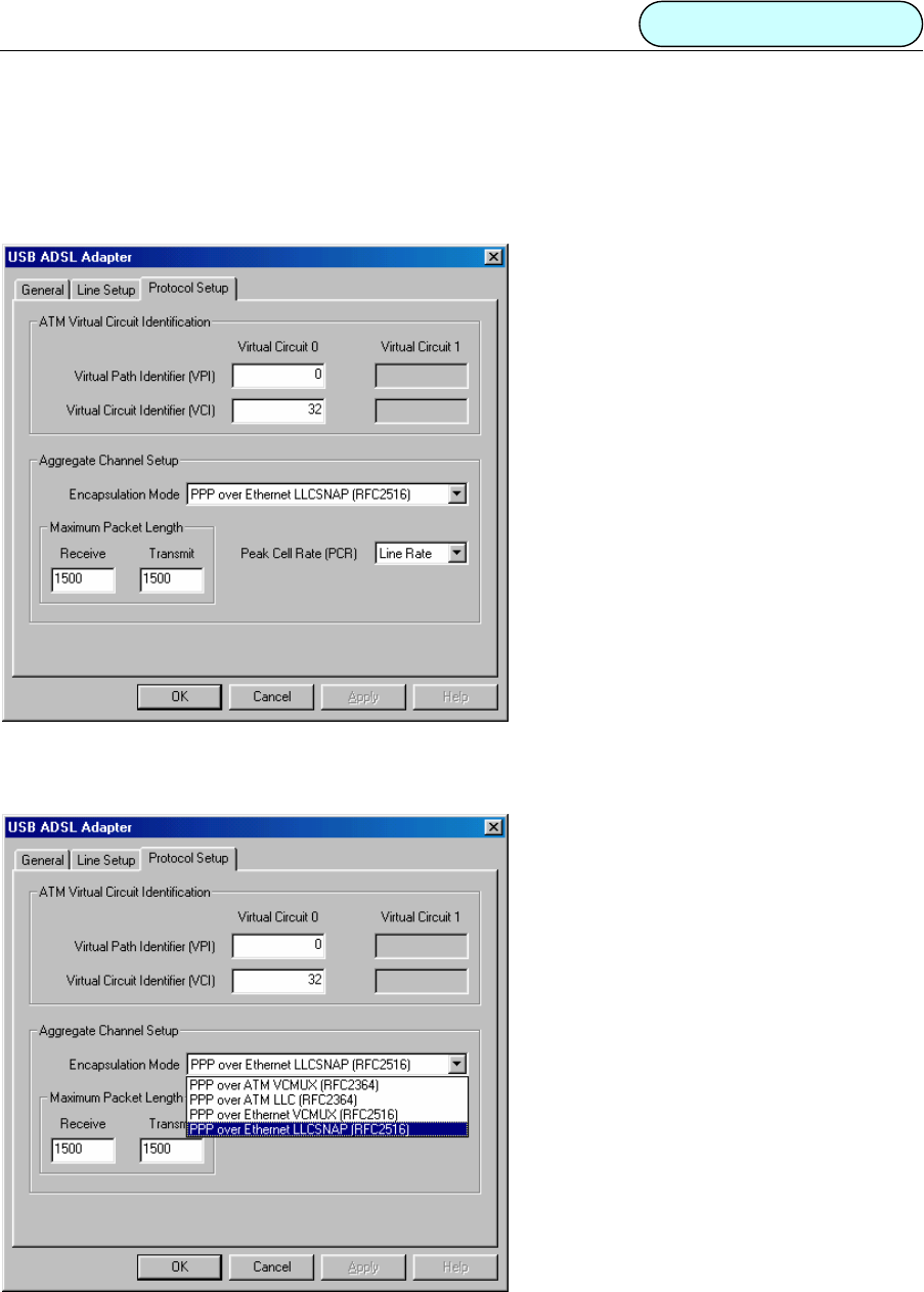
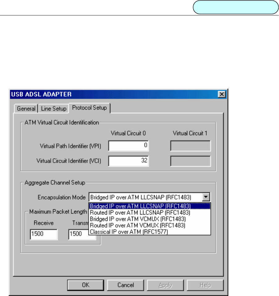
3. Press ALT+C and a control box will appear. The default parameters as shown below:
• The value of VPI and VCI are set to the value of VPI=0 & VCI=32.
• The Encapsulation mode is the default value “PPP over Ethernet LLCSNAP (RFC2516)”.
• The maxim cell speed is 1500. (Recommend not modifying).
• The maxim message package length is line rate. (Recommend not modifying).
Figure 3.4
4. If dial-up mode is PPPoA, then “PPP over ATM VCMUX(RFC2364) or PPP over ATM LLC
(RFC2364) ”should be selected in the “Encapsulation mode” box. As shown figure 3.5.
Figure 3.5
5Click “OK” button to finish the installation.
DB101 ADSL MODEM Manual
- 11 -
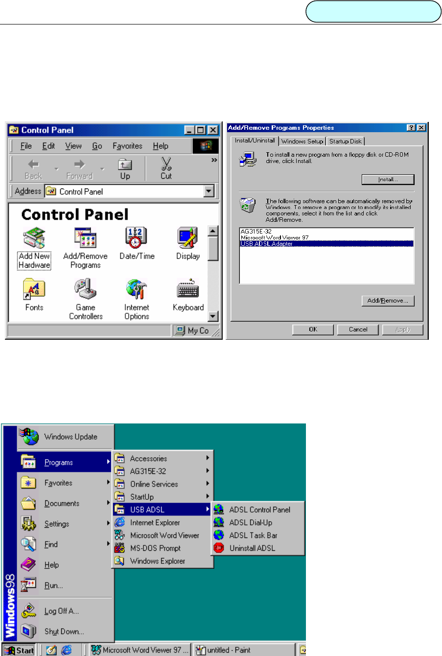
4. UNINSTALLATION
METHOD 1:
1. Click “Start” Æ “Settings” Æ “Control Panel”.Then double click “Add/Remove Program” icon in the
Control Panel window.
Figure 4.1 Figure 4.2
2. Select “USB ADSL Adapter” in the display dialog box and then click “Add/Remove” button. As shown
figure 4.2
METHOD 2
1Click “Start” Æ “Programs” Æ “USB ADSL” Æ “Uninstall ADSL”. As shown figure 4.3.
Figure 4.3
DB101 ADSL MODEM Manual
- 12 -
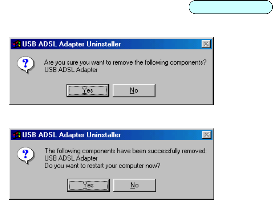
2. For either method it will ask you to click“Ye s”to confirm deletion. As shown figure 4.4.
Figure 4.4
3Click “Ye s ” to restart the computer. As shown figure 4.5.
Figure 4.5
DB101 ADSL MODEM Manual
- 13 -
5 CONNECTION SETUP
There are different kinds of connection: Physical Layer Connection, PPP Dial-Up Connection and Private
Connection. They will be introduced individually in this section.
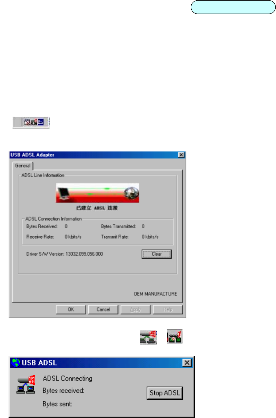
5.1 PHYSICAL LAYER CONNECTION
1. The Physical Layer Connection will automatically run after the telephone line is connected. The taskbar
shall be shown as below if the connection is good.
2. To check if the connection is OK, double click “ADSL CONTROL PANEL” on the desktop. If the following
box pop up, then the connection is fine.
Figure 5.1.1
3. To disconnect or reconnect, double click the icon or in the taskbar. A dialog box will
appear as figure 5.1.2. Click the “Stop ADSL” button to stop ADSL connection.
Figure 5.1.2
DB101 ADSL MODEM Manual
- 14 -
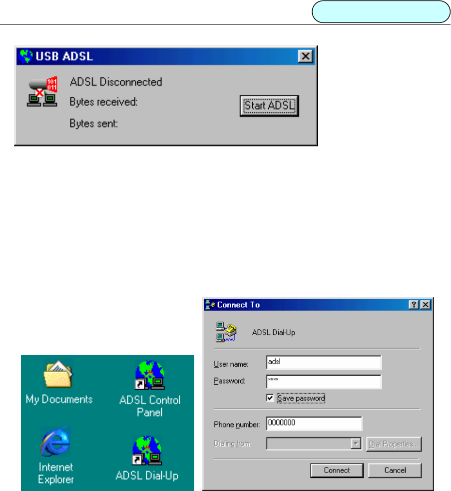
Figure 5.1.3
Or click the “Start ADSL” button to reconnect ADSL.
4You may now install PPP Dial-up connection after finishing the steps stated above for physical layer
connection.
5.2 DIAL-UP CONNECTION
Microsoft Windows® 98 v1.0 and v2.0
Before dialing, confirm the value of VPI, VCI and Encapsulation mode according to Chapter 3.
1 Double click the “ADSL dial -up” icon on the desktop
Figure 5.2.1 Figure 5.2.2
2 Input username and password and click the “connect” button to connect.
The procedure below is designed for connection properties modifications only. You may skip this if
no changes are needed.
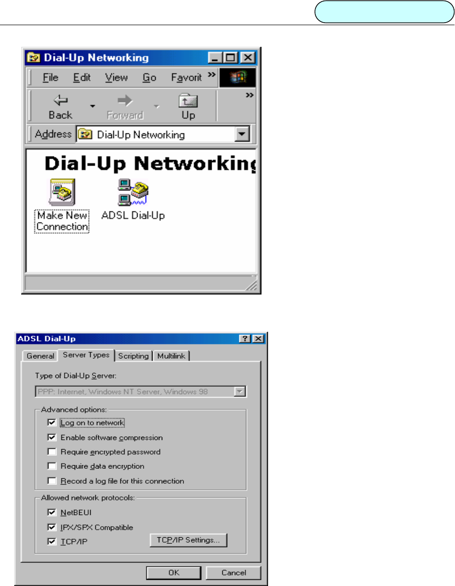
3 Right click “ADSL Dial up” icon and select “properties”.
DB101 ADSL MODEM Manual
- 15 -
Figure 5.2.3
Items can be modified are listed in the dialog box
Figure 5.2.4
4 Click the “OK” button to exit.
Windows® 2000
The configuration process is similar to Win98.
DB101 ADSL MODEM Manual
- 16 -
5.3 Private Line Connection
Microsoft Windows® 98
1 Install the LAN driver.
2 Set values for VPI, VCI and Encapsulation mode.
Figure 5.3.1
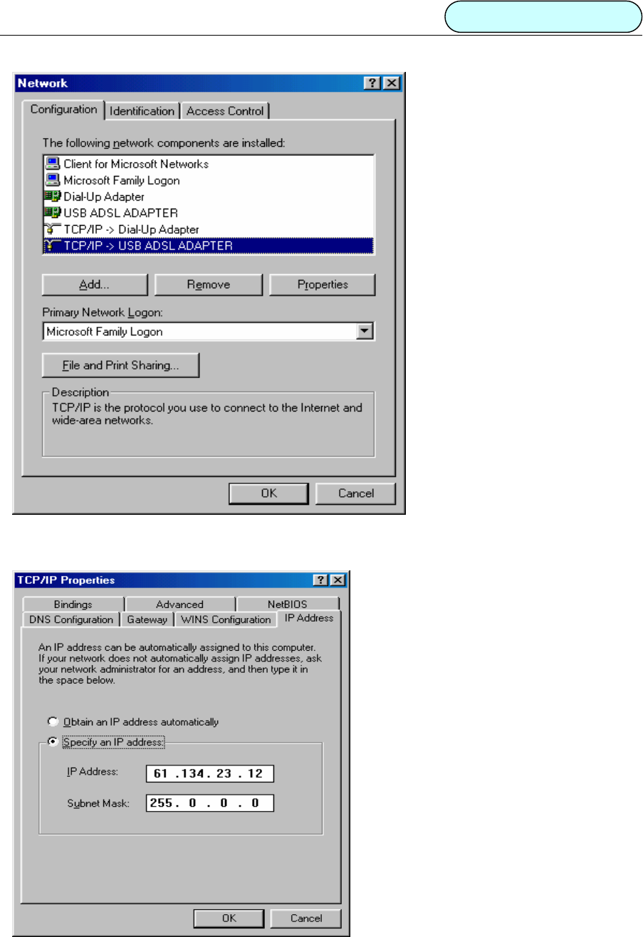
3 Double click the “Network” icon in “Control Panel”.
4 Choose the “Configuration” page, select “TCP/IP Æ USB ADSL Adapter” and click “Properties”. As shown
in figure 5.3.2.
DB101 ADSL MODEM Manual
- 17 -
Figure 5.3.2
Figure 5.3.3

DB101 ADSL MODEM Manual
- 18 -
5 In the “TCP/IP Properties” dialog box select the “IP Address” page. Select the “Specify an IP address” radial
box and input the correct IP address and subnet mask (you will need to contact your service provider to get
the correct value of the IP address and subnet mask). Or Select the “obtain IP address automatically” to skip
the step 6.
6 Input the correct IP address of DNS configuration and the Gateway property page.
7 Click “OK” button to exit the “TCP/IP Property” dialog box.
8 Click “OK” button in the pop-up “Networks” dialog box to finish the configuration of TCP/IP.
9 After modifying the property of TCP/IP, the system reminds the user to restart (Note: You don’t need to
restart for Windows®2000). Click the “OK” button to restart the computer immediately in order to make
the new settings valid.
Windows® 2000
The configuration process is similar to Win98.
6. PPPoE CONFIGURATION
1Method one:
• Follow the “Driver Installation” procedures to install “WAN Driver” and set values for VPI, VCI and
Encapsulation mode (see Chapter 3)
• Follow the “Connection Setup” procedures to install “Dial-up”.
2Method two:
• Install LAN driver and set VPI, VCI and Encapsulation mode.
• Install “Third party dial-up software”, for example, Enternet300, WinPoet, RasPPPoE, etc.
• Use third party dial-up software to connect to the Internet.

DB101 ADSL MODEM Manual
- 19 -
7. SPECIFICATION
7.1 POWER SUPPLY
z Uses USB bus for power. No power supply is needed.
z Power consumption ≤ 2.5W
7.2 DIMENSION
138mmLengthx 104mmWidthx 13mmHeight
7.3 WEIGHT
300g
7.4 CERTIFICATIONS
z EMI/Immunity: FCC Part 15 Class B, CE Mark (EN55022 Class B/EN50082)
z Security standardULEN60950
z CommunicationFCC Part 68,CYR21
z Electromagnetic: Compliant with FCC, ETSI and CISPR standard
7.5 OPERATING ENVIRONMENT
z Working temperature: -5 °C to 45 °C
z Working humidity: relative humidity from 10% to 90%
z EMIFCC PART15&68

DB101 ADSL MODEM Manual
- 20 -
APPENDIX A: GLOSSARY
ATU- C ADSL Transceiver Unit, Central Office End
ATU-R ADSL Transceiver Unit, Remote Terminal End
FEXT Far-end Cross Talk
HDSL High-rate Digital Subscriber Line
POTS Plain Old Telephone Service
PSTN Public Switched Telephone Network
WINS Windows® Internet Name Server
ADSL Asymmetric Digital Subscriber Line
OAM Operations, Administration And Maintenance
QAM Quadrature Amplitude Modulation
DMT Discrete Multitone
DSL Digital Subscriber Line
FEC Forward Error Correction
ATM Asynchronous Transfer Mode
WAN Wide Area Network
PRD Pseudo-random Downstream
PRU Pseudo-random Upstream
USB Universal Serial Bus
LAN Local Area Network
PVC Permanent Virtual Circuit
SVC Switched Virtual Circuit

DB101 ADSL MODEM Manual
- 21 -
PPP Point to Point protocol
DNS Domain Name Server
VPI Virtual Path ID
VCI Virtual Circuit ID
DSL Digital Subscriber Line
IP Internet Protocol
CO Central Office
EC Echo Canceling

DB101 ADSL MODEM Manual
- 22 -
APPENDIX B: Troubleshooting
Phenomena Suggested Solution
Power supply light is off. Make sure the USB connection is tight.
Power supply light is on, but
Link light is blinking.
• Check to see if the modulate and demodulate modes have
been correctly selected
• Make sure the phone line is connected to the modem.
Cannot establish connection
when dialing.
• Make sure the correct driver has been installed
• Make sure the VCI and VPI is configured correctly.
• Make sure the protocols selected are correct.
• Make sure you use the correct username and password.
• For Windows 2000 or Windows XP, de-select the “Use
LCP Extension” and “Use Software Compression” in the
dial up property page
• For Windows 98 de-select the options of “Log on
network”, keep only “TCP/IP”.
Cannot install drivers
• Confirm USB port is functioning properly.
• Confirm there is sufficient disk space and memory.
• Confirm the operating system supports USB.
• Check if viruses infect system.
Cannot uninstall driver • Check if processes have been correctly followed
according to the manual
Cannot reinstall
• Make sure you follow the instruction to uninstall the
drivers.
• In the device manager window, delete the driver for USB.
Cannot connect to the Internet
• Make sure the dial-up connection has been correctly
established.
• Re-configure “ADSL dial-up properties”, de-select “use IP
pointer compress”.
• If your computer has an Ethernet card, disable it when
using third party dial-up software.
The icon disappears in system
tray.
• Reinstall ADSL driver after normal boot up
• Reboot the computer
DB101 ADSL MODEM Manual
- 23 -
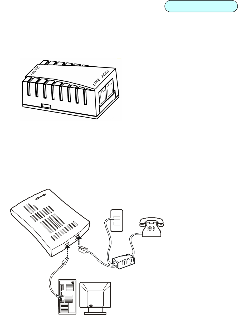
APPENDIX C: SPLITTER CONNECTION
Splitter
• Use a telephone cord to connect the LINE port of the splitter with the telephone RJ-11 port on the wall.
• Use another telephone cord to connect the ADSL port on the Splitter with the Line port on the ADSL
Modem.
• Use yet another telephone cord to connect the telephone with the Phone port of the Splitter.
Figure 1
DB101 ADSL MODEM Manual
- 24 -
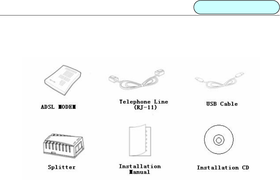
APPENDIX D: SHIPPING LIST

DB101 ADSL MODEM Manual
- 25 -
DARE TECHNOLOGIES CO., LTD.
Add: 12250 El Camino Real, #350
San Diego, CA 92130
USA
China Company:
22F, Shanghai Information Building, NO. 1555,
Kongjiang Road, Shanghai, China, 200092
Tel: (858) 755 8822
Fax: (858) 755 8896
www.dareglobal.com
www.dare-tech.com