Darfon Electronics U10B Wireless Bluetooth Keyboard User Manual Subject
Darfon Electronics Corp Wireless Bluetooth Keyboard Subject
User Manual
Subject: PRODUCT ENGINEERING
SPECIFICATION
Part No.: 9Z.P5E**.***; Rev.: 0
Doc. No.:
201-C001
Project Code:
9Z.P5E81.001
Page 1 of 33
Model Name:
U10B
Release Notice
Table of Contents……………………………………………………………………………………Page
1. Introduction .........................................................................................................................................3
2. Electrical specifications ........................................................................................................................3
2.1 Pseudo N-key rollover .................................................................................................................3
2.2 Cables and Connectors ................................................................................................................3
2.3 Connectors to match with ...........................................................................................................3
2.4 Safety and EMI Requirements .....................................................................................................4
2.5 Membrane Switch Electrical Requirements ................................................................................5
2.5.1 Contact resistance: ..........................................................................................................5
2.5.2 Bounce: ............................................................................................................................5
2.5.3 Dielectric strength: ..........................................................................................................5
3. Mechanical Specification .....................................................................................................................5
3.1 General Items ..............................................................................................................................5
3.1.1 Overall Dimensions/ Weight............................................................................................5
3.1.2 Keycap Legend .................................................................................................................6
3.1.3 Row offsets ......................................................................................................................6
3.1.4 Key Pitch ..........................................................................................................................6
3.1.5 Keycap Texture ................................................................................................................6
3.1.6 Color ................................................................................................................................6
3.1.7 Flammability of materials (Unless otherwise specified): ................................................8
3.1.8 Key Switch Function.........................................................................................................8
3.2 Mechanical Requirements.........................................................................................................10
3.2.1 Switch Operating Characteristics (silent tactile): ..........................................................10
3.2.2 Smoothness: ..................................................................................................................11
3.2.3 KB Strengths: .................................................................................................................11
4. Environment Test Specification .........................................................................................................13
4.1 Environment test items for keyboard function: ........................................................................13
4.1.1 High Temperature Operation ........................................................................................13
4.1.2 High Temperature and High Humidity Operation .........................................................13
4.1.3 High Temperature Storage ............................................................................................14
4.1.4 High Temperature and High Humidity Storage .............................................................14
4.1.5 Low Temperature Operation .........................................................................................14
Form No.: A-01-001-09(111107) 保存期限:最新狀態 保存單位:eGRNSystem
過期處置:背面紙
Subject: PRODUCT ENGINEERING
SPECIFICATION
Part No.: 9Z.P5E**.***; Rev.: 0
Doc. No.:
201-C001
Project Code:
9Z.P5E81.001
Page 2 of 33
Model Name:
U10B
Release Notice
4.1.6 Low Temperature Storage .............................................................................................14
4.1.7 Temperature Shock .......................................................................................................14
4.2 Environmental Data for reference only ....................................................................................15
4.2.1 H2S gas test: (reference) ...............................................................................................15
4.2.2 O3 gas test: (reference) .................................................................................................15
4.2.3 Altitude (reference): ......................................................................................................16
4.2.4 ESD test: (meet customer's requirement) .....................................................................16
5. Durability ............................................................................................................................................16
5.1 Life test ......................................................................................................................................16
5.2 Keycap Printing tests .................................................................................................................17
5.2.1 Legend Wear Resistance ...............................................................................................17
5.2.2 Keycap Chemical Resistance ..........................................................................................17
5.2.3 Paint Keycap Test ...........................................................................................................18
5.2.4 Boiling Test ....................................................................................................................22
5.3 Vibration Test ............................................................................................................................22
5.4 Drop Test ...................................................................................................................................23
5.5 Shock and Simple Shock Tests ...................................................................................................24
5.5.1 Shock test ......................................................................................................................24
5.5.2 Simple Shock Test ..........................................................................................................25
5.6 Water Spill test ..........................................................................................................................26
5.7 Coke Spill test ............................................................................................................................26
5.8 UV Stability ................................................................................................................................26
5.9 Hot plate test .............................................................................................................................26
6. Keyboard Layout ................................................................................................................................27
6.1 U10B Layout Drawing ................................................................................................................27
Appendix A (Appearance Spec) ..................................................................................................................28
Form No.: A-01-001-09(111107) 保存期限:最新狀態 保存單位:eGRNSystem
過期處置:背面紙
Subject: PRODUCT ENGINEERING
SPECIFICATION
Part No.: 9Z.P5E**.***; Rev.: 0
Doc. No.:
201-C001
Project Code:
9Z.P5E81.001
Page 3 of 33
Model Name:
U10B
Release Notice
1. Introduction
These specifications will give a description on the U10B keyboard modules designed to be installed
into the Notebook PCs. 64keys module for US versions. They are designed with excellent silent tactile
feeling by switch-stroke up to 1.1±0.2 mm full stroke and feeling technology improvements. And they
are different with keyboard technology (Backlit and Non backlit):
U10B: Printing legends and over coating for keycaps.
U10B: is a retail package, the key module is owned by Darfon.
2. Electrical specifications
2.1 Pseudo N-key rollover
The key module is pseudo N-key rollover, more than 2 key pressed at the same time are acceptable
except those keys are in the phantom position of scan matrix.
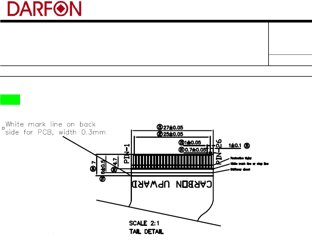
2.2 Cables and Connectors
The keyboards use 26 pins connector for system
The keyboards use 4 pins connector for backlit module
2.3 Connectors to match with
U10B keyboards use 26pins, 1mm pitch connector of ZJ.XFE(1.0C-26PBS) for system.
Form No.: A-01-001-09(111107) 保存期限:最新狀態 保存單位:eGRNSystem
過期處置:背面紙
Subject: PRODUCT ENGINEERING
SPECIFICATION
Part No.: 9Z.P5E**.***; Rev.: 0
Doc. No.:
201-C001
Project Code:
9Z.P5E81.001
Page 4 of 33
Model Name:
U10B
Release Notice
U10B
2.4 Safety and EMI Requirements
2.4.1 There shall be no over-standard EMI emitting from keyboard module while assembled
on the Notebook PC housing so as to assist notebook PC successfully granted by FCC
(class-B) & CE (class-B).
2.4.2 No clear coats or enamels will be used as a surface finish of the keyboard
mounting/base plate. Keyboard mounting/base plate should have good electrical
connection through mounting bosses and should be electrically connected to the main
keyboard plate.
2.4.3 The keyboard shall meet ISO 9241-4 requirements and all relevant national keyboard
layouts such as DIN2137 and ZH1/618. Must also meet all keycap inscription durability
requirements.
2.4.4 Keyboard module shall has potential to obtain the TUV approval, but unnecessary to
apply it unless special request from customer.
2.4.5 The keyboard module should be approved by UL.
Form No.: A-01-001-09(111107) 保存期限:最新狀態 保存單位:eGRNSystem
過期處置:背面紙
Subject: PRODUCT ENGINEERING
SPECIFICATION
Part No.: 9Z.P5E**.***; Rev.: 0
Doc. No.:
201-C001
Project Code:
9Z.P5E81.001
Page 5 of 33
Model Name:
U10B
Release Notice
2.5 Membrane Switch Electrical Requirements
2.5.1 Contact resistance:
Test method – Apply finger load on the center of keycap down to bottom, resistance must meet the
following: (pin end to end)
500-ohm max. (Initially)
1000-ohm max. (After life & Environmental testing)
2.5.2 Bounce:
Striking the center of key 3 times per second with load 400 grams, Contact bounce must be lower than
20 ms. (all the life time)
2.5.3 Dielectric strength:
Apply 100V A.C. across any adjacent circuit paths; and across circuit paths and metal plate. There shall
be no abnormality happening on circuit.
3. Mechanical Specification
3.1 General Items
3.1.1 Overall Dimensions/ Weight
Keyboard module overall dimensions and weight and key layouts.
(1). Dimensions:
Length: 229.9 ±0.1 mm
Width: 82.6 ±0.1 mm
Height: 3.0 ±0.2 mm
(2). Weight:
U10B: 46 grams (max)
Form No.: A-01-001-09(111107) 保存期限:最新狀態 保存單位:eGRNSystem
過期處置:背面紙
Subject: PRODUCT ENGINEERING
SPECIFICATION
Part No.: 9Z.P5E**.***; Rev.: 0
Doc. No.:
201-C001
Project Code:
9Z.P5E81.001
Page 6 of 33
Model Name:
U10B
Release Notice
3.1.2 Keycap Legend
U10B: Legends are made by laser etching or printing.
3.1.3 Row offsets
Defined by drawing.
3.1.4 Key Pitch
16.9 mm.
3.1.5 Keycap Texture
U10B NBL keycap texture is MT 11010.
U10B with BL keycap is polish 800.
3.1.6 Color
(1) Laser etch keycaps:
MCS-A0QN + MCS-A982 for U10B
Gloss: 6±1 units at 60 degrees
Sample appearance also needs to be approved by DARFON.
Paint:
Primer:
Paint: 大瑞 AP10101
Color: White
Dry film thickness: 12~16 µm
Color Coat:
Paint: 大瑞 AF1092
Color: Black
Dry film thickness: 14~18 µm
Protective Coating
Form No.: A-01-001-09(111107) 保存期限:最新狀態 保存單位:eGRNSystem
過期處置:背面紙
Subject: PRODUCT ENGINEERING
SPECIFICATION
Part No.: 9Z.P5E**.***; Rev.: 0
Doc. No.:
201-C001
Project Code:
9Z.P5E81.001
Page 7 of 33
Model Name:
U10B
Release Notice
UV coating: 大瑞 UV0093
Color: Clear
Dry film thickness: 12~18 µm
Gloss: 6±1 units at 60 degrees
MCS-A0UN + MCS-A982 for U10B
Gloss: 3±1 units at 60 degrees
Sample appearance also needs to be approved by DARFON.
Paint:
Primer:
Paint: 歐力生 ECONET EY MIDDLE GRAY BASE NO.2
Color: Gray
Dry film thickness: 10~14 µm
Color Coat:
Paint: 歐力生 ECONET EY KBD BEZEL WHITE
Color: White
Dry film thickness: 10~14 µm
Protective Coating
UV coating: 歐力生 UV COAT S-200 CLEAR HX -2
Color: Clear
Dry film thickness: 15~19 µm
Gloss: 3±1 units at 60 degrees
(2) Printing keycaps:
MCS-A0BU for U10B
Color of legend:
Print (Panton coolgray 3c)
Form No.: A-01-001-09(111107) 保存期限:最新狀態 保存單位:eGRNSystem
過期處置:背面紙
Subject: PRODUCT ENGINEERING
SPECIFICATION
Part No.: 9Z.P5E**.***; Rev.: 0
Doc. No.:
201-C001
Project Code:
9Z.P5E81.001
Page 8 of 33
Model Name:
U10B
Release Notice
MCS-A0C8 for U10B
Color of legend:
Print (Panton coolgray 8c)
(3) Note: Specification of keycap color comparison.
Refer to appendix A.
3.1.7 Flammability of materials (Unless otherwise specified):
Part Material UL grade Note
Keycap
ABS PA 758 – U10B BL
ABS PA 757 – U10B NBL 94 – HB
Paint + Laser Etching – U10B
Print – U10B
Rubber dome/return spring
Silicone (transparent) 94 – HB
Membrane
PET
94 – VTM2
Support plate
Stainless(SUS 304) – U10B
Thickness: 0.2mm
Scissors mechanism
POM or Darfon approved equivalent
94 – HB
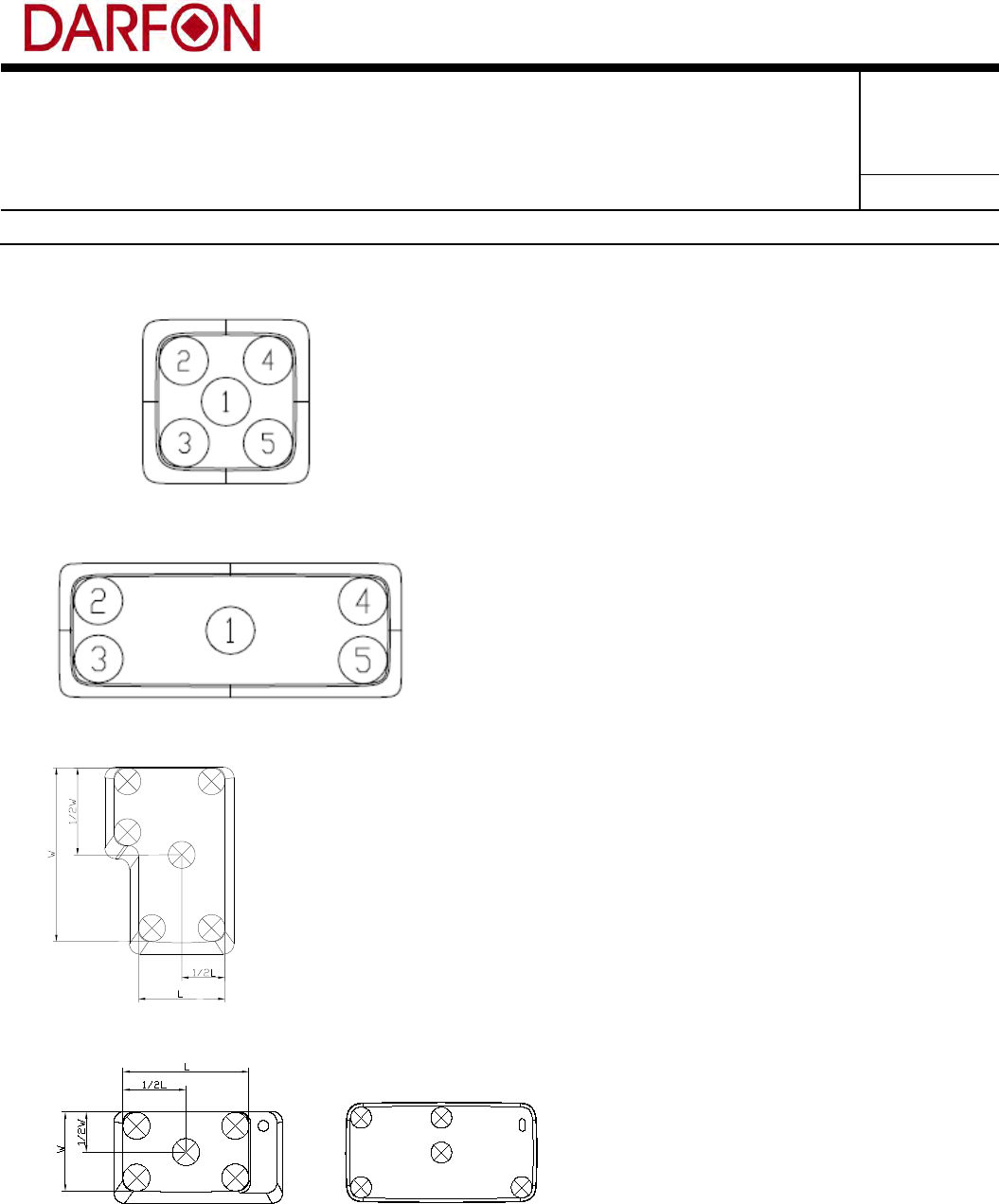
3.1.8 Key Switch Function
The keyboard should have well switch function by following definition.
Key-in SPEC as below:
Test probe diameter : ∅4.0mm
1. The measurement of P1 at corner < Nominal P1 at center *1.5
2. The force of fire point at corner< the P1 at corner
A. Small keys(Key size < 1.0X)
Form No.: A-01-001-09(111107) 保存期限:最新狀態 保存單位:eGRNSystem
過期處置:背面紙
Subject: PRODUCT ENGINEERING
SPECIFICATION
Part No.: 9Z.P5E**.***; Rev.: 0
Doc. No.:
201-C001
Project Code:
9Z.P5E81.001
Page 9 of 33
Model Name:
U10B
Release Notice
B. Normal keys
C. Multiple key and spacebar
D. Enter key
E. Special key(Caps lock key)
OR
Form No.: A-01-001-09(111107) 保存期限:最新狀態 保存單位:eGRNSystem
過期處置:背面紙
Subject: PRODUCT ENGINEERING
SPECIFICATION
Part No.: 9Z.P5E**.***; Rev.: 0
Doc. No.:
201-C001
Project Code:
9Z.P5E81.001
Page 10 of 33
Model Name:
U10B
Release Notice
3.2 Mechanical Requirements
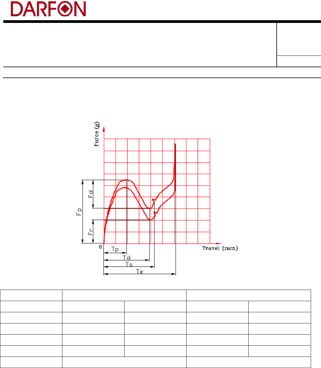
3.2.1 Switch Operating Characteristics (silent tactile):
Key Switch Specification for regular keys
Regular Keys Small Keys
Total Travel(Te) 1.1±0.2mm 1.1±0.3mm 1.1±0.2mm 1.1±0.3mm
Peak Force(Fp) 60±15g Min 50% of P1 60±15g Min 50% of P1
Peak Travel(Tp) 0.45±0.2mm 0.45±0.25mm 0.45±0.2mm 0.45±0.25mm
Drop Force(Fd) 35%~50% of Fp n/a 35%~50% of Fp n/a
Return Force(Fr) Min 15g Min 5g Min 15g Min 5g
Life Cycles 5 Million 2 Million
Placing the keyboard such that the direction of the keyboard operation is vertical and then
applying a static load twice the actuating force to the center of the key top, the travel distance
for the key top to come to a stop shall be measured.
Form No.: A-01-001-09(111107) 保存期限:最新狀態 保存單位:eGRNSystem
過期處置:背面紙
Subject: PRODUCT ENGINEERING
SPECIFICATION
Part No.: 9Z.P5E**.***; Rev.: 0
Doc. No.:
201-C001
Project Code:
9Z.P5E81.001
Page 11 of 33
Model Name:
U10B
Release Notice
3.2.2 Smoothness:
Press key at random, the key must be up and down actively and freely without slow return, rubbing or
sticking motions.
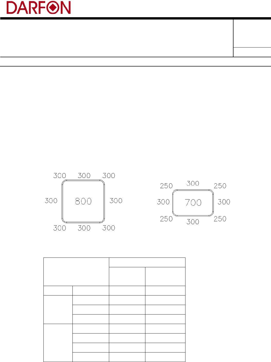
3.2.3 KB Strengths:
(1) Pull Off Force
Center pull off force (all keys, backlit)” 800g Minimum w/equal load applied to all 4
corners of the keycap edge and corner specs shown below:
Regular Small
Backlit
Regular
Key
Function
Key
Center All 800 g 700 g
Edge
Front 300 g 300 g
Rear 300 g 300 g
Side 300 g 300 g
Corner
Left Front 300 g 250 g
Right Front 300 g 250 g
Left Rear 300 g 250 g
Right Rear 300 g 250 g
Form No.: A-01-001-09(111107) 保存期限:最新狀態 保存單位:eGRNSystem
過期處置:背面紙
Subject: PRODUCT ENGINEERING
SPECIFICATION
Part No.: 9Z.P5E**.***; Rev.: 0
Doc. No.:
201-C001
Project Code:
9Z.P5E81.001
Page 12 of 33
Model Name:
U10B
Release Notice
Placing the keyboard such that the direction of keyboard operation is vertical, the
maximum pulling force required to remove a key cap shall be measured. The above
values are based on initial keycap removal test cycle. No permanent damage to any
component of the key switch should occur and no removal of any other component
(w/exception of leveling mechanism or wire on multi-wide keycaps) except the keycap
when the keycap pull test is performed. Keycap shall be easily replaceable by user.
(2) Keyboard stop strength:
There shall be no sign of damage, mechanically or electrically to the keyboard or point
stick (if applicable) when the keyboard is placed such that the direction of keyboard
operations is vertical, and a static load of the following force is applied in the direction
of keycap operation for a period of time or in the direction of stick operation.
A test shall be performed with the keyboard fixed to avoid keyboard warp and a test
probe 13.0mm in diameter minimum applied made of a high Durometer rubber so as
not to damage the keycap or point stick cap.
Operation Direction Load, N (Kg) Period (second)
Key cap Z 29.4 (3) 60
Stick XY 39.2 (4) 60
Stick Z 98 (10) 60
(3) Cable Strain Relief
The Cable, if applicable, on the keyboard shall have a minimum bend radius of 1.0mm
and a Strain Relief of 0.45kg in any direction.
(4) Flex Termination/Connector Mate and Un-Mate Life
The Keyboard Connection to the system (or Touchpad) interface shall support
twenty-five (25) mate/un-mate cycles at all possible angles of insertion (determined on
a product by product basis via Dell Engineering) without any functional degradation or
change in signal integrity outside of specification range.
(5) Keyboard Bending Strength
Form No.: A-01-001-09(111107) 保存期限:最新狀態 保存單位:eGRNSystem
過期處置:背面紙
Subject: PRODUCT ENGINEERING
SPECIFICATION
Part No.: 9Z.P5E**.***; Rev.: 0
Doc. No.:
201-C001
Project Code:
9Z.P5E81.001
Page 13 of 33
Model Name:
U10B
Release Notice
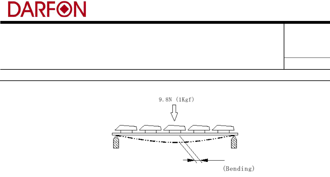
Figure. Keyboard Bending Strength
With the keyboard is placed on the bench supporting both at top and bottom end,
applying 9.8N (1 kgf) load to the center of keyboard, the keyboard bending should be
5mm maximum. During the test, the keycaps and scissors should not dislodge. After
the testing, the keyboard should be fully functional without any degradation and
mechanical damages.
4. Environment Test Specification
4.1 Environment test items for keyboard function:
4.1.1 High Temperature Operation
The keyboard shall be operable at 60oC without condensation continuously for a minimum 48 hrs.
There must be no evidence of internal corrosion or bacteria – fungus growth after the test.
4.1.2 High Temperature and High Humidity Operation
The keyboard shall be operable at 60oC at 90% humidity without condensation continuously for a
minimum 48 hrs. There must be no evidence of internal corrosion or bacteria – fungus growth after the
test.
Form No.: A-01-001-09(111107) 保存期限:最新狀態 保存單位:eGRNSystem
過期處置:背面紙
Subject: PRODUCT ENGINEERING
SPECIFICATION
Part No.: 9Z.P5E**.***; Rev.: 0
Doc. No.:
201-C001
Project Code:
9Z.P5E81.001
Page 14 of 33
Model Name:
U10B
Release Notice
4.1.3 High Temperature Storage
The keyboard shall be able to withstand storage at 70oC without condensation continuously for a
minimum 96 hrs. There must be no evidence of internal corrosion or bacteria – fungus growth after the
test.
4.1.4 High Temperature and High Humidity Storage
The keyboard shall be able to withstand at 70oC at 95% humidity without condensation continuously
for a minimum 96 hrs. There must be no evidence of internal corrosion or bacteria – fungus growth
after the test.
4.1.5 Low Temperature Operation
The keyboard shall be operable at 0oC continuously for a minimum 48 hrs without failure or any
degradation of performance.
4.1.6 Low Temperature Storage
The keyboard shall be able to withstand storage at -40oC continuously for a minimum 96 hrs without
failure or any degradation of performance.
4.1.7 Temperature Shock
The keyboard shall be able to withstand 12 cycles of thermal shock testing between –25oC and 60oC
external ambient temperatures (minimum 30oC/min. transition rates and 2 hr dwells at each extreme)
without failure or any degradation of performance.
Below test items for keyboard with backlit module:
Non-operational temperature/humidity(package with PE bag)
Test Step #
Conditions (from)
Conditions (to)
Elapsed time (hours)
Test purpose
Test Mode
1
25ºC/50% RH
-40ºC
4
Temperature and Humidity ramp
2
-40ºC
-40ºC
24
Low temperature soak
Cold
3
-40ºC
39ºC/0%RH
5
Temperature ramp (15C/hour)
4
39ºC/0%RH
39ºC/95%RH
5
Humidity ramp (20%/hour)
5
39ºC/95%RH
39ºC/95%RH
12
High humidity soak
Damp
Form No.: A-01-001-09(111107) 保存期限:最新狀態 保存單位:eGRNSystem
過期處置:背面紙
Subject: PRODUCT ENGINEERING
SPECIFICATION
Part No.: 9Z.P5E**.***; Rev.: 0
Doc. No.:
201-C001
Project Code:
9Z.P5E81.001
Page 15 of 33
Model Name:
U10B
Release Notice
6
39ºC/95%RH
65ºC/20%RH
4
Temperature and Humidity ramp
7
65ºC/20%RH
65ºC/20%RH
24
High temperature & high humidity soak
Hot
8
65ºC/20%RH
25ºC/50%RH
4
Temperature and Humidity ramp
Operational temperature/humidity(package with PE bag)
Test
Step #
Conditions
(from)
Conditions (to)
Operation
Duration
(hours)
Test purpose
Test
Mode
1
25ºC/50% RH
0ºC
Power On,
Function test
2
Temperature and Humidity
ramp
2
0ºC/10% RH
-------
Function test
12
Low temperature function test
Cold
3
0ºC
31ºC/90%RH
Function test
4
Temperature and Humidity
ramp
4
31ºC/90%RH
--------
Function test
12
High humidity test
Damp
5
31ºC/90%RH
40ºC/45%RH
Function test
3
Temperature and Humidity
ramp
6
40ºC/45%RH
--------
Function test
12
High temperature & high
humidity test
Hot
7
40ºC/45%RH
25ºC/50%RH
Function test
2
Temperature and Humidity
ramp
8
Go to step 1
Repeat steps 1-8 for
second cycle
Function test
47
Run 2nd loop undocked
Sample shall not show visual crack and deformation after test.
4.2 Environmental Data for reference only
Note: All test-sample to be oven cured 65°C at 24 hours at least prior to carrying out the following
tests to secure the sealing of membrane assembly.
4.2.1 H2S gas test: (reference)
3.0±1 ppm, 28°C, 90%±5% RH Non-Condensing, 200 hours, then reduce RH to 50%±5%RH, keep other
conditions, 50 hours. (250 hours in total)
4.2.2 O3 gas test: (reference)
2.5±0.3 ppm, 28°C, 90%±5% RH Non-Condensing, 200 hours, then reduce RH to 50%±5% RH, 50 hours.
(250 hours in total)
Criterion of 4.2.1 & 4.2.2:
Form No.: A-01-001-09(111107) 保存期限:最新狀態 保存單位:eGRNSystem
過期處置:背面紙

Subject: PRODUCT ENGINEERING
SPECIFICATION
Part No.: 9Z.P5E**.***; Rev.: 0
Doc. No.:
201-C001
Project Code:
9Z.P5E81.001
Page 16 of 33
Model Name:
U10B
Release Notice
1. No evidence degradation & No flux activity on membrane assembly. (Discoloration may be
acceptable if pass the following)
2. Max. loop Contact resistance (switch contacted) to be less than 1 KΩContact Resistance
Increasing Less then 30 %.
3. Pass the basic function test & switch reaction test (4 strikes/sec).
4. Pass the trace-peeling test.
4.2.3 Altitude (reference):
10K ft, Operating, 35K ft Non-Operating.
Criterion: Basic functional test shall be passed.
4.2.4 ESD test: (meet customer's requirement)
“The keyboard must be designed to be immune up to 8kVcontact discharges to any exposed conductive
surfaces and up to 15kV air discharges to any part of the keyboard that will attract an ESD event. This
immunity, applies to any part of the keyboard which could be damaged from such a discharge. In
addition, the keyboard when integrated into the system must afford immunity at the system level to said
discharges.
Air discharges will seek areas or points that have a difference of potential from the tip of the ESD
generator (path of least impedance). This usually means, but is not limited to, ‘ground’ potential. All
circuit traces should be either insulated in a fashion to prevent an ESD event from occurring and/or have
a “safe” ground potential from which the discharge is attracted. In either case, the design of the keyboard
must be made to disallow any discharges to circuit traces.
5. Durability
5.1 Life test
Switch life must exceed a life expectancy of 10 million actuation (2 million for Function and Cursor
keys). This life performance must be demonstrated by actual testing using 150 grams minimum
Form No.: A-01-001-09(111107) 保存期限:最新狀態 保存單位:eGRNSystem
過期處置:背面紙
Subject: PRODUCT ENGINEERING
SPECIFICATION
Part No.: 9Z.P5E**.***; Rev.: 0
Doc. No.:
201-C001
Project Code:
9Z.P5E81.001
Page 17 of 33
Model Name:
U10B
Release Notice
actuation force at a 3-5 cycles per second frequency. After testing individual keys must function
properly. If keycap have linkbar, after life test the linkbar can’t come off.
Item Requirement
Cycle Rate 3-5 times/sec
Keys 20 keys minimum
Force 150g at full travel
Stress cycles 5 / 3 million cycles for normal key / fun & cursor key
Sample size 20 keys per keyboard
Time between intervals 24 hours
Force displacement measurements and keyboard functionality will be tested at the following intervals: 0, 5, and 10
million cycles. The keyboards will be tested 24 hours after the end of each interval.
The minimum keys to be tested shall include: E, A, G, X, Esc, Left Shift, Enter, and Spacebar center (2 keyboard min),
Spacebar left end (1 keyboard min) and Spacebar Right end (1 keyboard min) as part of the 20 key minimum
requirement stated above.
5.2 Keycap Printing tests
5.2.1 Legend Wear Resistance
The keyboard legend life should be compliant with IEC 68-2-70 standard “Abrasion of Markings and
Letterings by Rubbing of Fingers and Hands” with a severity level for of 1.5N(153g) at 5 million cycles.
5.2.2 Keycap Chemical Resistance
The keyboard surface, including all key caps, shall resist erosion due to common chemicals that exist on
persons during use of the keyboard. These common chemicals include hand lotion (Oil of
Olay,Vaseline, and Sunscreen), hand cleaner, perfume and cologne.
Resistance to erosion by wiping the above mentioned chemicals onto the surface of the keyboard shall
be verified and the erosion under a 40oC temperature environment for 24 hours minimum shall be
observed.
Form No.: A-01-001-09(111107) 保存期限:最新狀態 保存單位:eGRNSystem
過期處置:背面紙
Subject: PRODUCT ENGINEERING
SPECIFICATION
Part No.: 9Z.P5E**.***; Rev.: 0
Doc. No.:
201-C001
Project Code:
9Z.P5E81.001
Page 18 of 33
Model Name:
U10B
Release Notice
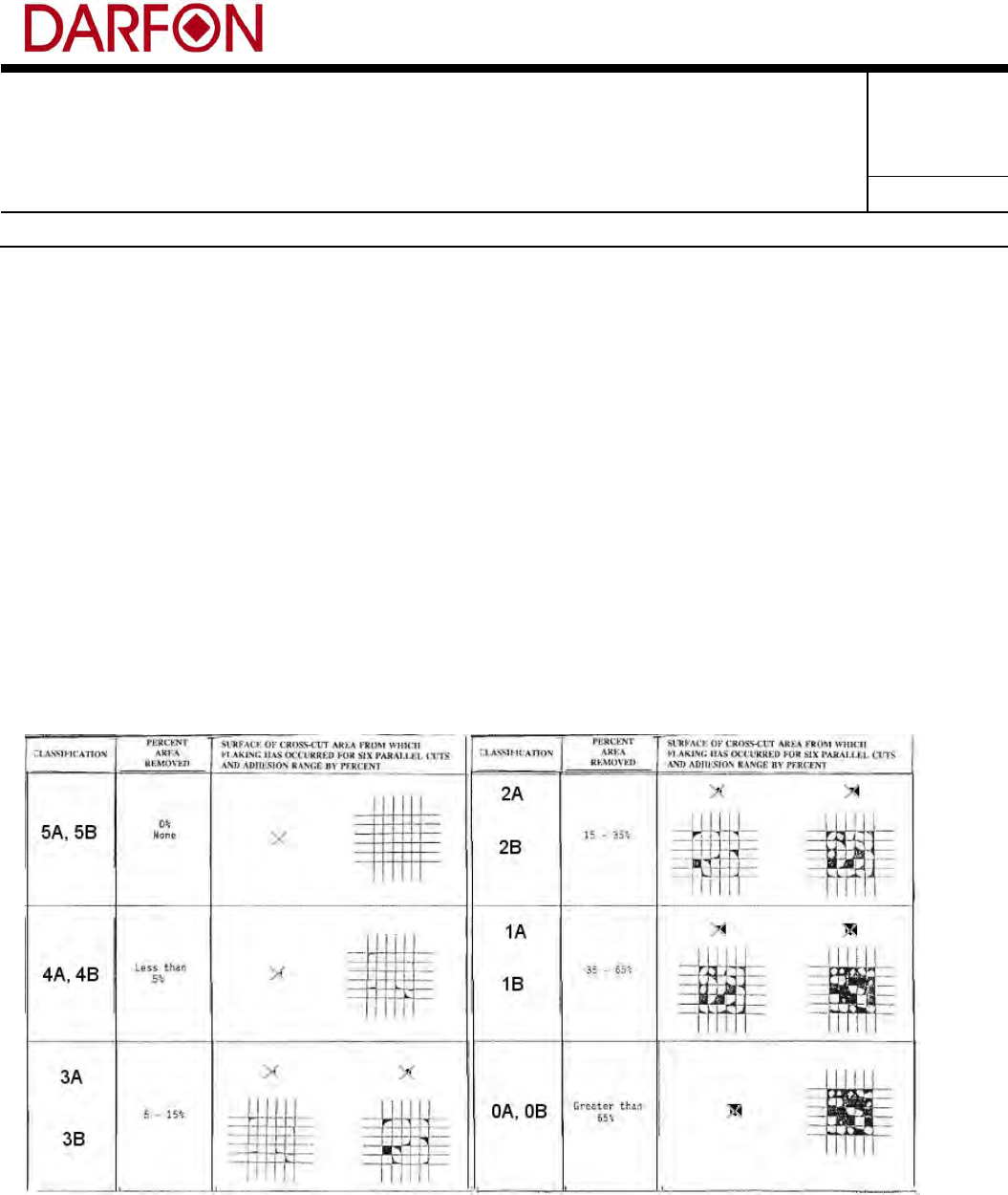
5.2.3 Paint Keycap Test
a. Adhesion (ASTM D3359-02)
Test Parameters:
Curved surfaces or surfaces too small (with one dimension less than 10mm) for Cross-cut – use
Method A, “X-cut Tape Test” – Permacell, 3M 250 tape, (or equivalent) shall be used for testing
purposes.
Flat surfaces – where possible, use Method B, “Cross-cut Tape Test,” – Permacell, 3M 250 tape (or
equivalent) shall be used for testing purposes.
Pass Criteria:
4A minimum, (trace peeling or removal along incisions or intersection), for all coating technologies
when using method A, (X-cut).
4B minimum, (less than 5% of the area removed), for all coating technologies when using method B,
(cross-hatch).
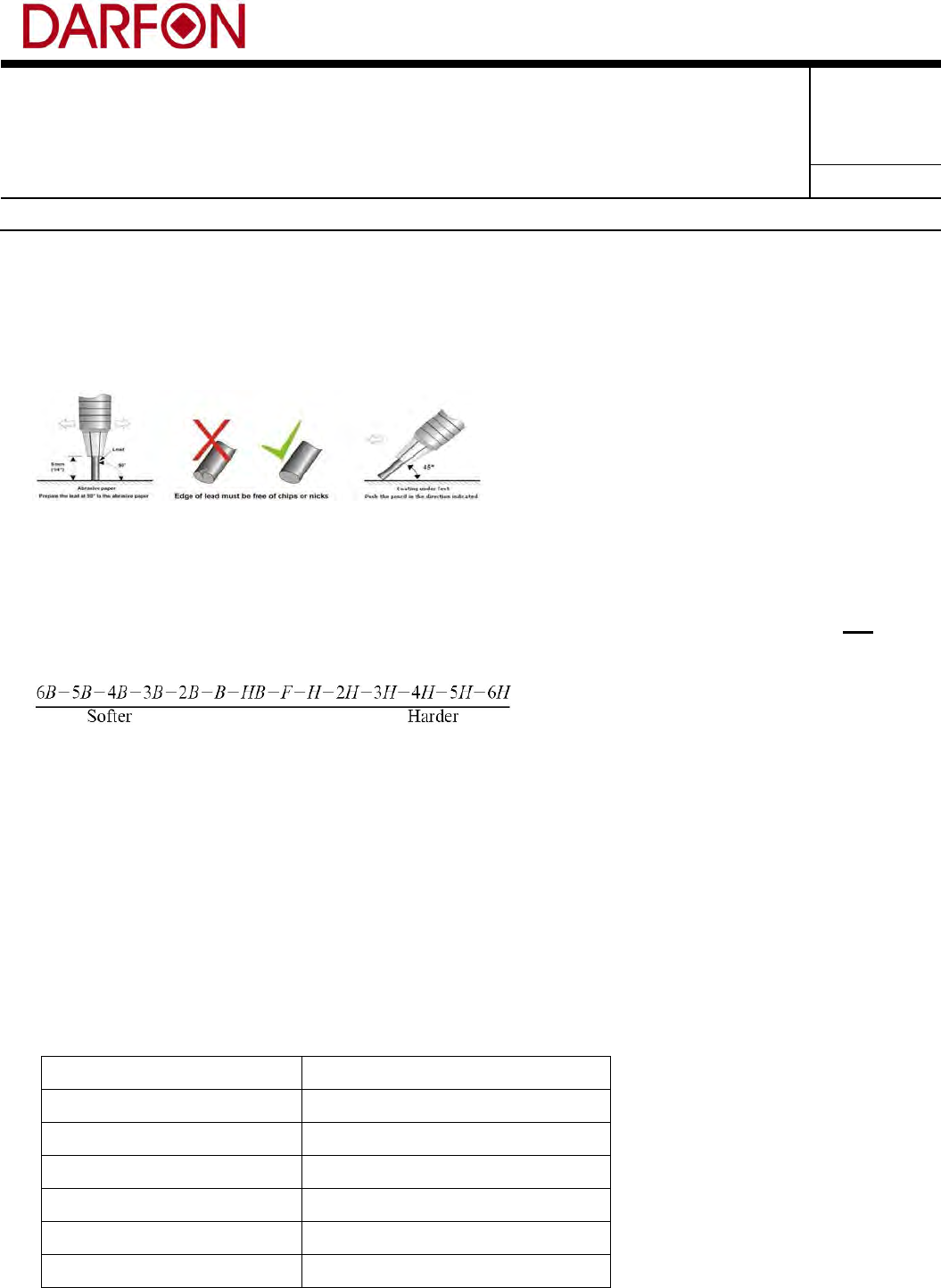
b. Film (Pencil) Hardness (ASTM D3363)
Test Parameters:
Follow the test method as defined in the ASTM D3363 standard. Calibrated pencils that meet the
hardness scale in section 5.1 of the ASTM D3363 standard are required.
Form No.: A-01-001-09(111107) 保存期限:最新狀態 保存單位:eGRNSystem
過期處置:背面紙
Subject: PRODUCT ENGINEERING
SPECIFICATION
Part No.: 9Z.P5E**.***; Rev.: 0
Doc. No.:
201-C001
Project Code:
9Z.P5E81.001
Page 19 of 33
Model Name:
U10B
Release Notice
Piece part test location for hardness test shall be determined by the piece part drawing. If the
specific test location is not called out, test will be performed in the same area as color and gloss
measurements.
Pencil preparation / use:
Begin testing with the hardest lead in an environment controlled to 25°C ±2°C, 50% ±5% relative
humidity on a flat, firm, horizontal surface with the pencil positioned at a 45° angle to the surface.
Repeat the process of selecting and testing with progressively softer leads until a lead is identified
which fails to scratch the surface. Record the coating hardness as the hardest lead that will not
scratch the surface. Repeat 3 times to confirm the accuracy of your conclusion.
Pass Criteria:
Checks shall be made by close visual inspection and fingernail feel. There shall be no visible cuts
or scratches per ASTM D3363 when viewed under cool white fluorescent light of 80 to 120
foot-candles at a distance of 18 inches, (460 mm). Inspectors should hold the part 30 degrees
from the horizontal plane and rotate the part 30 degrees to the left and right along the vertical axis.
Pencil hardness is indicated by the hardest pencil that will leave the film uncut and unscratched.
Any defacement of the surface other than a cut (gouge) is considered a scratch. In some cases
pencil lead transfer to the surface may be misinterpreted as a scratch. Verify that scratches are
indeed scratches by removing any residual pencil lead marks with dry or moist cloth before making
the scratch determination.
1. 2K low bake H or harder
2. 1K high bake 2H or harder
3. Powdercoat 2H or harder
4. UV H or harder
5. 1K low bake HB or harder
6. Soft Touch F or harder
7. IMR HB or harder
Form No.: A-01-001-09(111107) 保存期限:最新狀態 保存單位:eGRNSystem
過期處置:背面紙
Subject: PRODUCT ENGINEERING
SPECIFICATION
Part No.: 9Z.P5E**.***; Rev.: 0
Doc. No.:
201-C001
Project Code:
9Z.P5E81.001
Page 20 of 33
Model Name:
U10B
Release Notice
8. Thermal Ink Transfer H or harder
9. Plated Finish H or harder
10. Conductive Coatings H or harder
11. NCVM H or harder
12. ED H or harder
13. Carbon Fiber Composite H or harder
c. Cure (Solvent Resistance) (ASTM D4752)
Test Parameters:
1. 2K low bake 50 double rubs MEK (100%)
2. 1K high bake 50 double rubs MEK (100%)
3. Powdercoat 50 double rubs MEK (100%)
4. UV 50 double rubs MEK (100%)
5. 1K low bake 50 double rubs IPA (70%)
6. Soft Touch 50 double rubs MEK (100%)
7. IMR 50 double rubs MEK (100%)
8. Thermal Ink Transfer 50 double rubs MEK (100%)
9. Plated Finish 50 double rubs MEK (100%)
10. Conductive Coatings 50 double rubs MEK (100%)
11. Silk Screen / Pad Print 50 double rubs IPA (70%)
12. NCVM 50 double rubs MEK (100%)
13. ED 50 double rubs MEK (100%)
14. Carbon Fiber Composite 50 double rubs MEK (100%
IPA – Isopropyl Alcohol - CAS # 67-63-0
MEK – Methyl Ethyl Ketone - CAS # 78-93-3
Form No.: A-01-001-09(111107) 保存期限:最新狀態 保存單位:eGRNSystem
過期處置:背面紙
Subject: PRODUCT ENGINEERING
SPECIFICATION
Part No.: 9Z.P5E**.***; Rev.: 0
Doc. No.:
201-C001
Project Code:
9Z.P5E81.001
Page 21 of 33
Model Name:
U10B
Release Notice
Resistance
Rating
Description
5
No effect on surface; no color on cloth after 50 double rubs.
4
Burnished appearance in rubbed area; slight amount of color on cloth after 50
double rubs.
3
Some marring and apparent depression of the film after 50 double rubs.
2
Heavy marring; obvious depression in film after 50 double rubs.
1
Heavy depression in the film but no actual penetration to the substrate after 50
double rubs.
0
Penetration to the substrate after 50 double rubs or less.
d. Norman Abrasion (ASTM F2357)
Test Parameters:
Equipment: Norman Tool or RCA abraser
Subject the test specimen to abrasion with 175g weight .
1. 2K low bake 60 cycles
2. 1K high bake 50 cycles
3. Powdercoat 150 cycles
4. UV 150 cycles
5. IMR 50 cycles
6. Thermal Ink Transfer 50 cycles
7. Plated Finish 50 cycles
8. Conductive Coatings 50 cycles
9. Silk Screen / Pad Print 50 cycles
10. NCVM 150 cycles
11. ED 50 cycles
12. Carbon Fiber Composite 50 cycles
13. Anodized 150 cycles
Pass Criteria:
No visual wear through the primary paint layer to either the substrate or a different color coating
layer after the specified number of cycles listed below are completed.
e. Compacted wool felt test
Keycap finish (e.g. gloss) shall be determined on a product by product basis and stay within drawing
tolerance for 100,000 cycles.
Form No.: A-01-001-09(111107) 保存期限:最新狀態 保存單位:eGRNSystem
過期處置:背面紙
Subject: PRODUCT ENGINEERING
SPECIFICATION
Part No.: 9Z.P5E**.***; Rev.: 0
Doc. No.:
201-C001
Project Code:
9Z.P5E81.001
Page 22 of 33
Model Name:
U10B
Release Notice
Item Requirement
Test Wheel Felt, Taber CS-5
Load 200g
Stroke 36 mm
Frequency 3 cycles/second
Number of cycles 100,000
5.2.4 Boiling Test
Poured pure water into waterbath, and set up the constant temperature to 60℃. When temperature
rise to the constant (60±3℃), put the object into waterbath and boil for 2 hours, object must be
immersed in water during the test. Placed the object which surface has been wiped down for 30 min.
Test Equipment: Waterbath
Specification
Externals must be regular, whitening, bubble and others are unacceptable.
5.3 Vibration Test
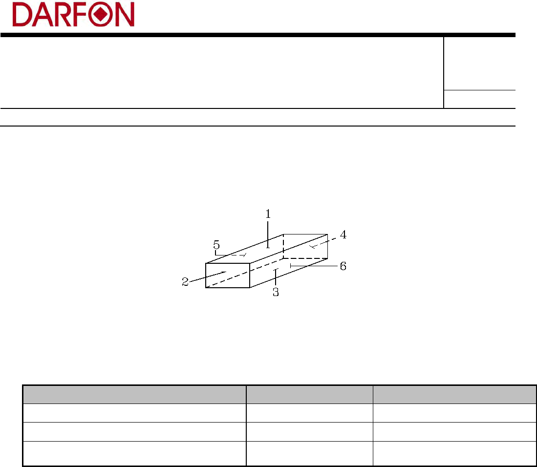
All tests below must be performed in each of the following planes:
Top side to bottom side;
Left side to right side; and
Front side to back side.
The fixture should be as rigid as possible so as not to distort the vibration imparted to the keyboard.
Securely fasten the fixture and keyboard to the vibration table so that it will not leave the surface of
the table during testing.
Measuring Method:
1. Random Non-Operational Vibration
The keyboard shall be able to withstand vibration of 2.1 GRMS, (truck/air) spectrum for duration of
30 minutes per side.
2. Sinusoidal Non-Operational Vibration
The keyboard shall be able to withstand vibration of 0.5 GRMS from 5-500 Hz at a sweep rate of 0.5
octaves per minute. The total dwell time at each major resonance shall be 15 minutes.
Form No.: A-01-001-09(111107) 保存期限:最新狀態 保存單位:eGRNSystem
過期處置:背面紙
Subject: PRODUCT ENGINEERING
SPECIFICATION
Part No.: 9Z.P5E**.***; Rev.: 0
Doc. No.:
201-C001
Project Code:
9Z.P5E81.001
Page 23 of 33
Model Name:
U10B
Release Notice
Judgment:
Meet the KB module requirements and no keycaps failing out/all key switches function OK.
5.4 Drop Test
(1) Drop Test – Packaged
All keyboards in the bulk and individual shipping package shall be able to withstand being dropped
on 3 edges and six sides. No key caps shall dislodge and there will be no deformation in the
keyboard structure. The keyboard shall be operational and the mechanism will continue to function
in a smooth and fluid motion. The drop height is determined according to the table below:
Measuring Method:
1. Condition: Package, non-operating.
Package Drop Height (Dell Specification)
Mass of Packaged Container
(lbs) (kg)
Drop Height
(inch) (cm)
0 - 10 0 - 4.5 42 106
11 - 24 4.6 - 11.0 36 91
25 - 45 11.1 - 20.5 30 76
46 - 75 20.6 - 34.0 24 61
76 - 100 34.1 - 45.5 18 46
2. Ten drops: 1 corner, 3 edges and 6 surfaces, as follows:
a. A corner drop with the weakest corner of product determined by the concern mechanical
engineer.
b. An edge drop with impact on the shortest edge radiating from the corner.
c. An edge drop with impact on the next shortest edge radiating from the corner.
d. An edge drop with impact on the longest edge radiating from the corner.
e. A flat drop with impact on the rear side.
f. A flat drop with impact on the front side.
g. A flat drop with impact on the right side.
h. A flat drop with impact on the left side.
i. A flat drop with impact on the bottom side.
Form No.: A-01-001-09(111107) 保存期限:最新狀態 保存單位:eGRNSystem
過期處置:背面紙
Subject: PRODUCT ENGINEERING
SPECIFICATION
Part No.: 9Z.P5E**.***; Rev.: 0
Doc. No.:
201-C001
Project Code:
9Z.P5E81.001
Page 24 of 33
Model Name:
U10B
Release Notice
j. A flat drop with impact on the top.
Judgment:
Meet the requirement of no keycaps falling out & all key switches are OK in function.
(2) Drop Test – Unpackaged
All unpacked keyboards shall be fully operational and without mechanical degradation after being
dropped from the heights below. No key caps or scissors shall dislodge during the test.
Measuring Method:
Drop Surface Height, mm Drop Orientation
Wood Desk 300 Corner
Wood Desk 400 Edges
¼”Industry carpet surface over steel or
concrete floor
600 Surface
Judgment:
All unpacked keyboards shall be fully operational and without mechanical degradation after being
dropped from the heights below. No key caps or scissors shall dislodge during the test.
5.5 Shock and Simple Shock Tests
5.5.1 Shock test
(1) Shock test – half sine wave
System Test: Shock level of 80 inches per second at 2 millisecond half sine.
Keyboard Only Test: Shock level of 400 G’s at 2 millisecond half sine (performed by
keyboard manufacturer
Judgment: The structure would remain in condition without loose keycaps and deformation of
module
Form No.: A-01-001-09(111107) 保存期限:最新狀態 保存單位:eGRNSystem
過期處置:背面紙
Subject: PRODUCT ENGINEERING
SPECIFICATION
Part No.: 9Z.P5E**.***; Rev.: 0
Doc. No.:
201-C001
Project Code:
9Z.P5E81.001
Page 25 of 33
Model Name:
U10B
Release Notice
(2) Shock test – square wave
Keyboard Only Test: The keyboard shall withstand not less than a 60 G faired square wave
with velocity at 5080 mm/sec (200 in/s).
Judgment: The structure would remain in condition without loose keycaps and deformation
of module.
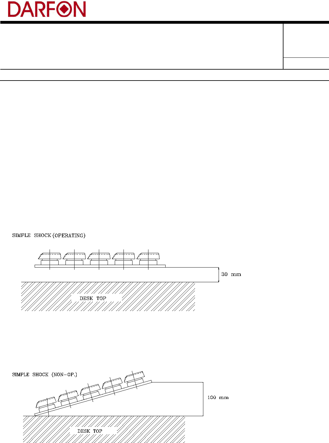
5.5.2 Simple Shock Test
(1) Measuring Method 1: Operating, non-packaged.
Drop from 3cm high from the desktop as shown. (Total 4 side each side 3 times)
Judgment: Without any wrong output from monitor screen except the characters of 1.5x, 2x, and
2x above keys.
(2) Measuring Method 2: Non-operating, non-packaged.
.Randomly drop the non-packaging keyboard (face us as shown) from 10cm high to the desk for 3
times.
Judgment: The structure would remain in condition without loose keycaps and deformation of
module.
Form No.: A-01-001-09(111107) 保存期限:最新狀態 保存單位:eGRNSystem
過期處置:背面紙
Subject: PRODUCT ENGINEERING
SPECIFICATION
Part No.: 9Z.P5E**.***; Rev.: 0
Doc. No.:
201-C001
Project Code:
9Z.P5E81.001
Page 26 of 33
Model Name:
U10B
Release Notice
5.6 Water Spill test
Equipment required for test: Kept at room temperature, Water, Small containers
Use a syringe or small container to pour 20cc (20 mL, about 2/3 fluid ounce) of water on three evenly
spaced spots on the keyboard: A and S, G and H L and ;. The total liquid will be 60cc (60mL, about
2.03 fluid ounces).The spill locations are between the following keys. Wait 60 minutes then remove the
liquid from the keyboard, taking care to limit the motions to only one axis ,type on all keys to verify
functionality.
5.7 Coke Spill test
Equipment required for test: Kept at room temperature, Diet CokeTM, Small containers
Use a syringe or small container to pour 20cc (20 mL, about 2/3 fluid ounce) of Diet Coke™ on three
evenly spaced spots on the keyboard: A and S, G and H L and ;. The total liquid will be 60cc (60mL,
about 2.03 fluid ounces). The spill locations are between the following keys.
Immediately tilt the keyboard towards its left side in an attempt to remove the liquid from the system,
taking care to limit the motions to only one axis
Wipe down surfaces of system with paper towels for exactly 45 seconds to remove as much visible
moisture as possible. Wait 60 minutes type on all keys to verify functionality.
5.8 UV Stability
The keyboard UV stability shall be in compliance with ASTM D4674 - 89. The test is applied to the color
of the key caps and legend. After the test, the materials used in the keyboard, shall not exhibit
significant cosmetic defects such as fading, flaking, crazing, or color change with ∆E of 1.0 or above.
The mechanical properties of the materials shall not be degraded to an extent which causes the system
to fail any of the life, shock or vibration tests.
5.9 Hot plate test
The Keyboard must put on temperature 80℃ hot plate, It need to endure 24 hour test, If the
keyboard function OK this test is pass, else is fail.
Form No.: A-01-001-09(111107) 保存期限:最新狀態 保存單位:eGRNSystem
過期處置:背面紙
Subject: PRODUCT ENGINEERING
SPECIFICATION
Part No.: 9Z.P5E**.***; Rev.: 0
Doc. No.:
201-C001
Project Code:
9Z.P5E81.001
Page 27 of 33
Model Name:
U10B
Release Notice
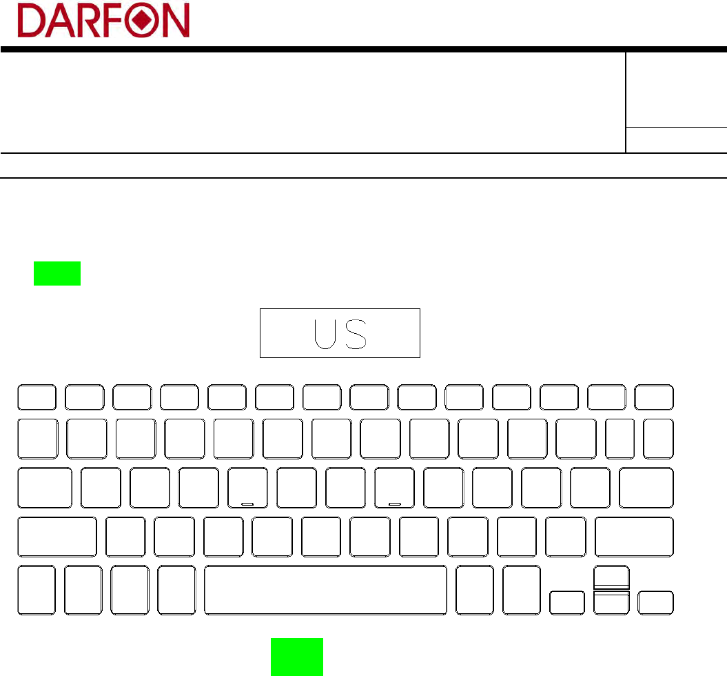
6. Keyboard Layout
6.1 U10B Layout Drawing
U10B US Layout
Form No.: A-01-001-09(111107) 保存期限:最新狀態 保存單位:eGRNSystem
過期處置:背面紙
Subject: PRODUCT ENGINEERING
SPECIFICATION
Part No.: 9Z.P5E**.***; Rev.: 0
Doc. No.:
201-C001
Project Code:
9Z.P5E81.001
Page 28 of 33
Model Name:
U10B
Release Notice
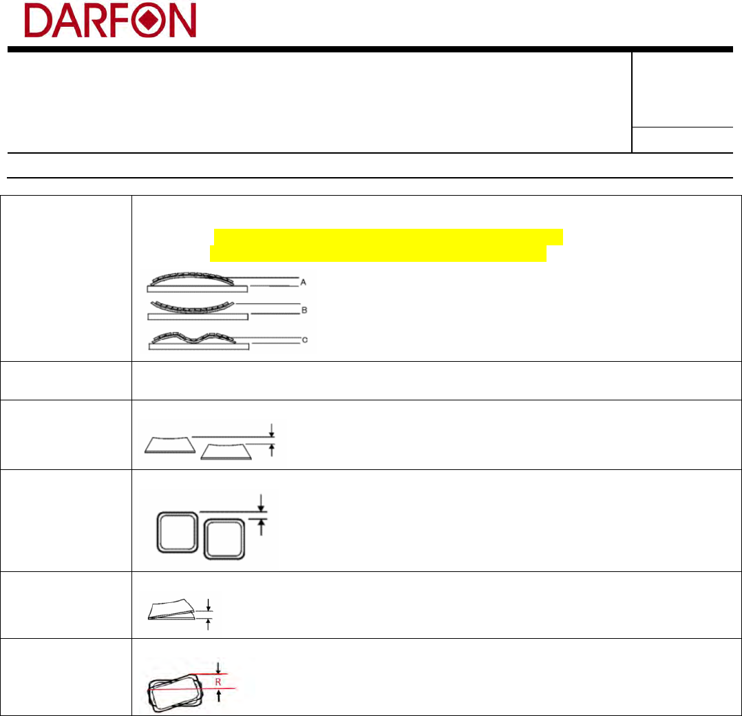
Appendix A (Appearance Spec)
Item
Normal
Backlit
IMR
Definition of
Keycap surface
A, B, C
Viewing angle,
distance and
lighting
requirement for
inspection
300mm, 45°(from horizontal), 800Lux ~ 1200Lux
Discolored
spots(
異色點
)
Surface A: <0.1mm²
Surface B, C: <0.2mm²
Scratch for
Keycap
Sensed scratch: surface A, B, C <0.1mm²
Senseless scratch and tiny scratch found by special angle view: less than 5.0mm length
Flash for Keycap
Surface A, B: ≤0.08mm
Surface C: ≤0.1mm
≤0.2mm
Shrink for
Keycap
Non-uniform texture: No detect is acceptable by 30mm normal visual review or by
golden sample.
Mark and shrink: The shadow that Keycap structure located is acceptable but the area of
shrink or ejection gate mark must be smaller than 0.3mm².
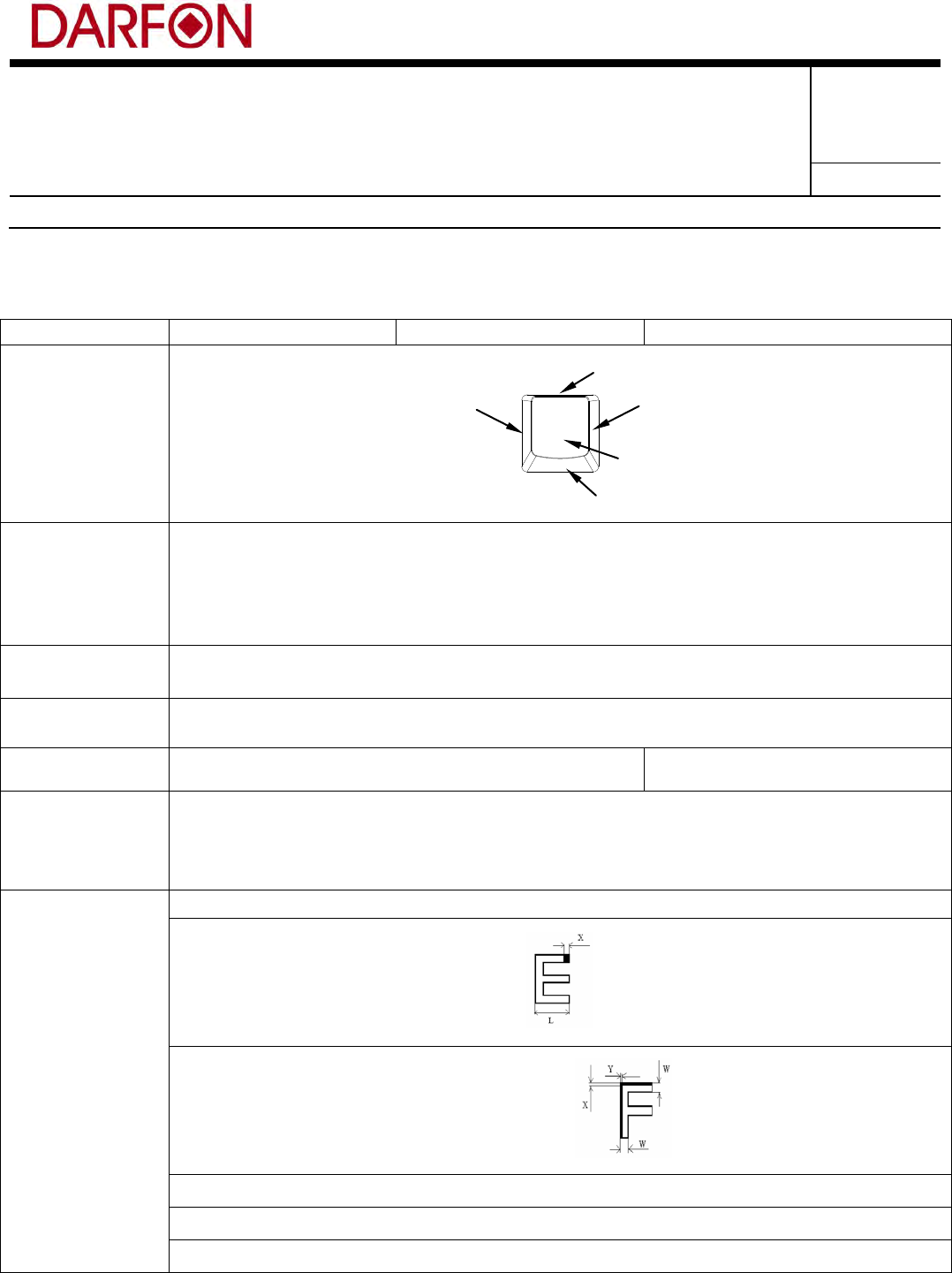
Appearance of
legend printing
Broken printing(
印刷斷字
) ≤1/3 width
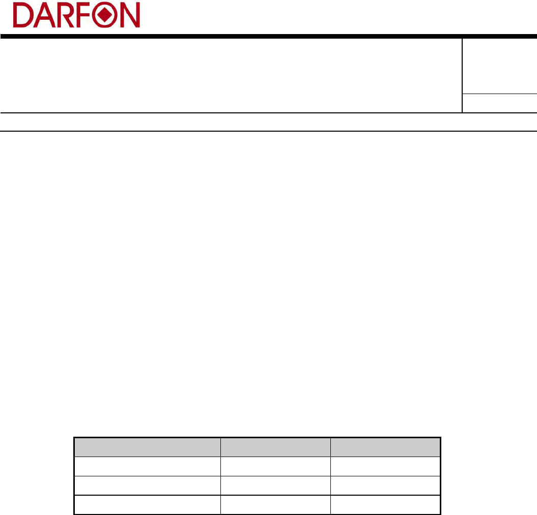
Line cut(印刷缺損) <1/8L, as following:
Width of line(字體粗細) ≤0.3W, as following:
Legend shift(字體偏移) ≤0.3mm
Sawtooth type printing(鋸齒狀字體) ≤0.08mm
Printing pin hole(印刷空點) ≤0.05mm²
A
B
C
B
A
Form No.: A-01-001-09(111107) 保存期限:最新狀態 保存單位:eGRNSystem
過期處置:背面紙
Subject: PRODUCT ENGINEERING
SPECIFICATION
Part No.: 9Z.P5E**.***; Rev.: 0
Doc. No.:
201-C001
Project Code:
9Z.P5E81.001
Page 29 of 33
Model Name:
U10B
Release Notice
Coating heap(堆疊) ≤0.1mm²
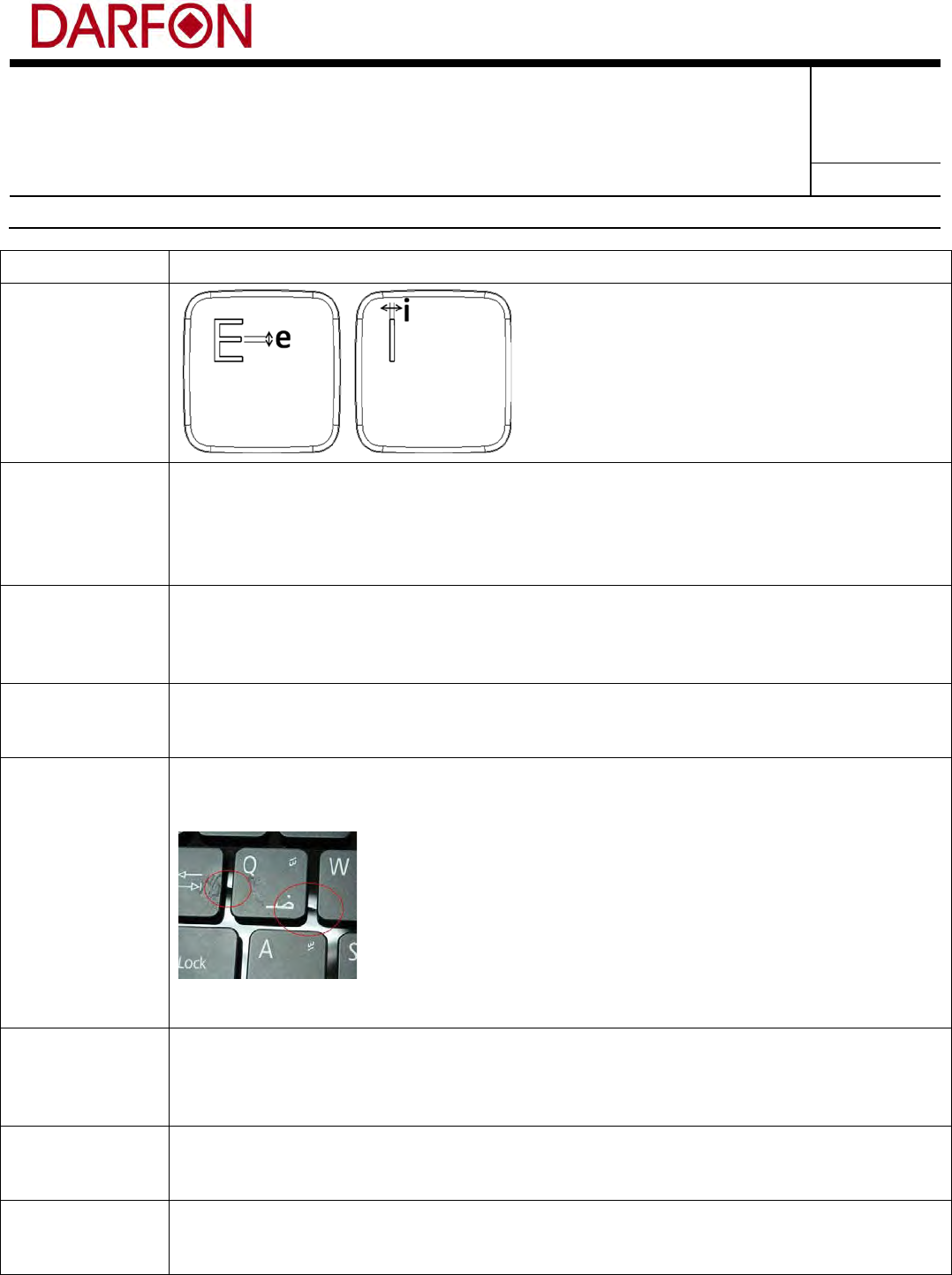
Appearance of
laser etching
legend
”e” & “i” width tolerance is ±0.05mm
Folding mark of
MEM tail
No function issue, mark can’t be through MEM tail width and broken surface can’t be
acceptable.
The amount of “LINE” type folding mark is not more than two and the gap between them
is larger than 10mm.
The amount of “SPOT” type folding mark is not more than four.
Arch for RUB
Mylar
Folding edge of metal plate: Arched height of RUB Mylar must be lower than folding
edge of metal plate with normal function.
No folding edge of metal plate: Arched height of RUB Mylar must be lower than 1/2
height between Keycap and metal plate(Z height).
Scratch for RUB
Mylar
Scratch with raw material: ≤0.2mm²
Sensed scratch without raw material: Width ≤0.1mm, Length ≤3mm
Senseless scratch: Width ≤0.2mm, Length ≤10mm
Folding mark of
RUB Mylar or
PET
Folding mark direction by X-direction: It is acceptable to be less than 3 marks for whole
keyboard but can’t be found on adjacent locations and the distance must be larger than
100mm between 2 marks; The following picture is NG sample.
Folding mark direction by Y-direction: Length <5mm, less than 3 marks for whole
keyboard.
Appearance of
AL Foil
1. Break can’t be acceptable.
2. Folding mark length <1/3 long length of Foil and not more than 3 marks within each
50mm.
3. Senseless scratch and finger marks can be acceptable.
Paint appearance
of metal plate
edge
Paint loss area ≤0.2mm²
Specification of
Keycap color
comparison
△E <1.0, △L, a, b <0.4
Form No.: A-01-001-09(111107) 保存期限:最新狀態 保存單位:eGRNSystem
過期處置:背面紙
Subject: PRODUCT ENGINEERING
SPECIFICATION
Part No.: 9Z.P5E**.***; Rev.: 0
Doc. No.:
201-C001
Project Code:
9Z.P5E81.001
Page 30 of 33
Model Name:
U10B
Release Notice
Keyboard warp
No warp spec: 0 ±1.5mm
Warp spec:
Short side: 0mm <A <0mm; 0.5mm <B <2mm; 0mm <C <0.5mm
Long side: 0mm <A <0mm; 0mm <B <2mm; 0mm <C <0.5mm
Gap between
keys
Gap G between keys: G±0.4mm
Gap G between keys and frame: G±0.3mm
Keycap height
alignment
Less than 0.4mm between neighboring keys by surface A.
Keycap
alignment in the
row
Less than 0.4mm between neighboring keys.
Keycap slant
Less than 0.3mm
Keycap twist
Less than 0.3mm for Normal Key;0.2mm for FUN key.
Form No.: A-01-001-09(111107) 保存期限:最新狀態 保存單位:eGRNSystem
過期處置:背面紙

Subject: PRODUCT ENGINEERING
SPECIFICATION
Part No.: 9Z.P5E**.***; Rev.: 0
Doc. No.:
201-C001
Project Code:
9Z.P5E81.001
Page 31 of 33
Model Name:
U10B
Release Notice
FCC Statement:
Federal Communications Commission (FCC) Statement
15.21
You are cautioned that changes or modifications not expressly approved by the part responsible for
compliance could void the user’s authority to operate the equipment.
15.105(b)
This equipment has been tested and found to comply with the limits for a Class B digital device,
pursuant to part 15 of the FCC rules. These limits are designed to provide reasonable protection
against harmful interference in a residential installation. This equipment generates, uses and can
radiate radio frequency energy and, if not installed and used in accordance with the instructions, may
cause harmful interference to radio communications. However, there is no guarantee that interference
will not occur in a particular installation. If this equipment does cause harmful interference to radio or
television reception, which can be determined by turning the equipment off and on, the user is
encouraged to try to correct the interference by one or more of the following measures:
-Reorient or relocate the receiving antenna.
-Increase the separation between the equipment and receiver.
-Connect the equipment into an outlet on a circuit different from that to which the receiver is
connected.
-Consult the dealer or an experienced radio/TV technician for help.
This device complies with Part 15 of the FCC Rules.
Operation is subject to the following two conditions:
1) this device may not cause harmful interference and
2) this device must accept any interference received, including interference that may cause undesired
operation of the device.
FCC RF Radiation Exposure Statement:
Form No.: A-01-001-09(111107) 保存期限:最新狀態 保存單位:eGRNSystem
過期處置:背面紙
Subject: PRODUCT ENGINEERING
SPECIFICATION
Part No.: 9Z.P5E**.***; Rev.: 0
Doc. No.:
201-C001
Project Code:
9Z.P5E81.001
Page 32 of 33
Model Name:
U10B
Release Notice
This equipment complies with FCC radiation exposure limits set forth for an uncontrolled environment.
End users must follow the specific operating instructions for satisfying RF exposure compliance. This
transmitter must not be co-located or operating in conjunction with any other antenna or transmitter.
Industry Canada (IC) Statement
Canada, Industry Canada (IC)
This Class B digital apparatus complies with Canadian ICES-003 and RSS-210.
This device complies with Industry Canada licence-exempt RSS standard(s).
Operation is subject to the following two conditions: (1)this device may not cause interference, and
(2)this device must accept any interference, including interference that may cause undesired operation
of the device.
Canada, avis d'Industry Canada (IC)
Cet appareil numérique de classe B est conforme aux normes canadiennes ICES-003 et RSS-210.
Son fonctionnement est soumis aux deux conditions suivantes : (1) cet appareil ne doit pas causer d'interférence et (2) cet
appareil doit accepter toute interférence, notamment les interférences qui peuvent affecter son fonctionnement.
Informations concernant l'exposition aux fréquences radio (RF)
La puissance de sortie émise par l’appareil de sans fil Darfon Electronics Corp. est inférieure à la limite d'exposition aux
fréquences radio d'Industry Canada (IC). Utilisez l’appareil de sans fil Darfon Electronics Corp.de façon à minimiser les
contacts humains lors du fonctionnement normal.
Form No.: A-01-001-09(111107) 保存期限:最新狀態 保存單位:eGRNSystem
過期處置:背面紙

Subject: PRODUCT ENGINEERING
SPECIFICATION
Part No.: 9Z.P5E**.***; Rev.: 0
Doc. No.:
201-C001
Project Code:
9Z.P5E81.001
Page 33 of 33
Model Name:
U10B
Release Notice
cULus Caution
CAUTION
RISK OF EXPLOSION IF BATTERY IS REPLACED
BY AN INCORRECT TYPE.
DISPOSE OF USED BATTERIES ACCORDING
TO THE INSTRUCTIONS
ATTENTION
IL Y A RISQUE D'EXPLOSION SI LA BATTERIE EST REMPLACÉE
PAR UNE BATTERIE DE TYPE INCORRECT.
METTRE AU REBUT LES BATTERIES USAGÉES
CONFORMÉMENT AUX INSTRUCTIONS
Form No.: A-01-001-09(111107) 保存期限:最新狀態 保存單位:eGRNSystem
過期處置:背面紙