Data Flow Systems VOY1-2 Voyager Telemetry Radio User Manual XX XXXX Exhibit Cover
Data Flow Systems Inc Voyager Telemetry Radio XX XXXX Exhibit Cover
Manual

5015 B.U. Bowman Drive Buford, GA 30518 USA Voice: 770-831-8048 Fax: 770-831-8598
Certification Exhibit
FCC ID: IQ5-VOY1-2
FCC Rule Part: CFR 47 Part 90.259
ACS Report Number: 09-0301-LD
Applicant: Data Flow Systems Inc.
Model: Voyager 1 Radio
Manual
Voyager
TelemetryRadio
Oct2009
RevisionA.3

QuickStartProcedure
FollowthestepsbelowtoinstallandconfigureVoyagerTelemetryRadio(VTR):
1. SelectthelocationfortheVTR.Mustbeanareafreeofwaterintrusionwitha
temperaturerangeof‐30to+55degC(‐22to130degF).
2. Locatethecoaxialcabletotheantenna.Thisshouldbeagoodquality,low‐losscable
thatisasshortaspossible.Thiscableshouldincludeanin‐linesurgearrestorto
preventlightningstrikedamagetotheradio.ThecableshouldhaveaBNC(F)
connectororanadapterwillbeneeded.
3. Locatethepowersource.TheVTRrequiresa9‐14VDCinputanddrawsabout1.5A.
PowerissuppliedviatheDB9connector(Pin5:+VDCandPin9:Ground)orplugon
thesideoftheradio,dependingontheoptionselected.VerifythatDCpoweris
suppliedonlyonPin5orthepowerplugisavailable.TheTablebelowsummarizesthe
properpinoutfortheserialdatacable:
Pin Function
1 TransmitData(fromuser)
2 ReceiveData(touser)
3 TransmitEnable(WSRtransmitswhenpinisgrounded)
4 Commonsignal&powerground
5 +10to14VDCinput
6 Squelch(Receive)
7 Frequencyprogramming(Notused)
8 RSSI(Strongsignal=3VDC)
9 Commonsignal&powerground
4. ConnecttheDB9orpowercabletotheVTRandturnthepowersourceon.Observe
thatthegreenpowerLEDisilluminated.Ittakesabout10secondsfortheVTRto
boot‐up.Afterthis,onlythegreenpowerLEDshouldbeon.
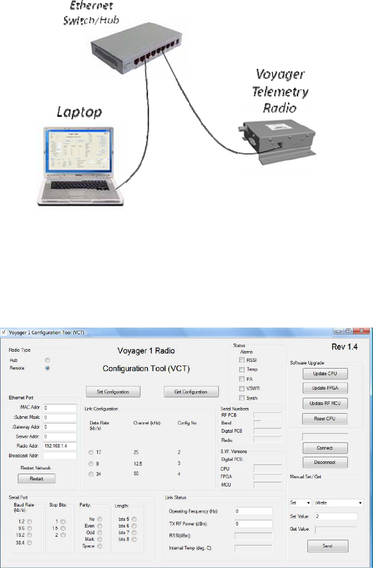
5. ConnectalaptoptotheVTRasshowninthefigurebelow(viaEthernetHuborSwitch.
LoadandstarttheVoyagerConfigurationTool(VCT)software.
6. ThedefaultIPaddressoftheVRTis192.168.1.4.Thisaddressisautomaticallyloadedin
theRadioAddressfieldoftheVCT.Clickontheconnectbutton(SeeFigurebelow).
Theword‘Connected’willappearintheboxabovethebuttonwhenanIPconnectionhas
beenestablishedbetweentheVCTandtheVTR.
7. Clickonthe‘GetConfiguration’button.TheVCTscreenwillthenbeupdatedwiththe
currentconfigurationinformationstoredwithintheVRT.
8. EthernetPortConfiguration:EnterthedesiredchangestotheSubnetMask,Server,
Gateway,BroadcastandRadioaddresses.BesuretorecordthenewRadioAddress.
Clickonthe‘SetConfiguration’button.TheVCTwillautomaticallyclose.Re‐startVCT
andenterthenewRadioIPaddressintheappropriatefieldonthescreenandpressthe
‘Connect’button.Theword‘Connected’shouldappearafterafewsecondsindicatinga
connectionhasbeenestablishedusingthenewradioIPaddress.
9. RadioTypeandLinkConfiguration:SelectthedesiredLinkConfigurationfromthemenu
choicesintheLinkConfigurationbox(1‐4).SelecttheRadioTypeasHub,Remoteor
FTUfromtheRadioTypebox.Clickonthe‘SetConfiguration’button.TheVCTwill
automaticallycloseastheVTRwillrestartwiththenewconfigurationinformation
permanentlystoredinmemory(untilchangedinthefuture).Re‐startVCTandenterthe
newRadioIPaddressintheappropriatefieldonthescreenandpressthe‘Connect’
button.Theword‘Connected’shouldappearafterafewsecondsindicatinga
connectionhasbeenestablishedusingthenewradioIPaddress.
10. TransmitRFPowerandOperatingFrequency:Enterthedesiredoperatingfrequencyof
theVTRintheappropriatefield.Thismustbeavaluebetween217.0and220.0MHz.
Thefrequencymustbedivisibleby12.5kHz.EnterthedesiredtransmitRFpowerinthe
appropriatefieldonthescreen.ThismustbeavalueindBmbetween14and33.Click
onthe‘SetConfiguration’button.
11. Clickonthe‘GetConfiguration’buttontoretrievealltheconfigurationstoredwithinthe
VTR.Verifythateachconfigurationparameteriscorrectlysettothedesiredvalue.
Notesomeparametersarereadonlyandcannotbechanged.TheseincludetheRSSI,
InternalTemperature,AlarmsandMACAddress.
12. VerifythattherearenoAlarmsindicatedintheStatusbox.

Contents
1.0ProductDescription............................................................................7
2.0Applications........................................................................................9
3.0Specifications...................................................................................11

CopyrightNotice
Copyright2009,DataFlowSystems,Inc,Allrightsreserved
OperationalandSafetyNotices
RFExposure
TheradiodescribedinthismanualtransmitsRFenergy.Theconcentratedenergyfromthe
antennamayposeahealthhazard.Allantennasusedwiththisradiomustbeinstalledto
provideaminimumseparationfromallpersonsof90cm(36inches).Theaboveseparation
distancemustbemaintainedatalltimes.MoreinformationcanbeobtainedfromtheFCCat
thefollowingwebsite:
http://www.fcc.gov/Bureaus/Engineering_Technology/Documents/bulletins/oet65/oet65.pdf
FCCPart15Notice
ThetransceivercomplieswithPart15oftheFCCRules.Operationissubjecttothefollowing
twoconditions:(1)thisdevicemaynotcauseharmfulinterference,and(2)thisdevicemust
acceptanyinterferencereceived,includinginterferencethatmaycauseundesiredoperation.
Anyunauthorizedmodificationorchangestothisdevicewithouttheexpressapprovalof
DataFlowSystemsmayvoidtheuser’sauthoritytooperatethisdevice.Furthermore,this
deviceisindentedtobeusedonlywheninstalledinaccordancewiththeinstructionsoutlined
inthismanual.Failuretocomplywiththeseinstructionsmayalsovoidtheuser’sauthorityto
operatethisdevice.
1.0ProductDescription
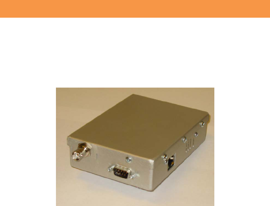
TheVoyagerTelemetryRadio(VTR)showninFigure1.1belowisdesigntoprovideareliable
wirelessconnectionfordigitalcommunicationinselectedbandsinthe200and400MHz
frequencybands.
Figure1.1:VoyagerTelemetryRadio(VTR)
TheVRTisasoftware‐definedradio(SDR)makingitveryflexibleandupgradable.Themodem
functionalityiscomprisedofsoftwarewhichisloadedatthetimeofmanufacturing.Itcanbe
upgradedinthefuturetoaddadditionalfeatures.
Theunitishousedinanaluminumenclosurewhichisnotweather‐tight.Twoprintedcircuit
boardsareincluded;RFandDigital.TheRFboardisprovidedinoneofthreeconfigurationsas
outlinedbelow:
LowBand:145to225MHz
MiddleBand:210to470MHz
HighBand:470to930MHz
TheseRFcardsallprovideacommondifferentialbasebandI/QinterfacetotheDigitalboard.
TheRFboardincludestransmit,receive,synthesizerandcontrolsections.Thetransmitsection
includesanIntermediatePowerAmplifier(IPA).PowerAmplifier(PA),VariableAttenuatorand
ForwardandReversePowerDetectors.ThePAprovidesnearly2Watts(32dBm)ofRFoutput
powerattheantennaconnector.TheVariableAttenuatorisusedbytheControlsystem
processortosetandmaintainthetransmittedRFpowerlevel.Aclosed‐loopprocessisused
withtheForwardPowerDetectortomaintainthedesiredoutputlevelunderallconditions.
TheReversePowerDetectorisusedtodetectimpedancemismatcheswhichmayoccurwithan
antennaorcablefailure.
ThereceivesectionoftheRFboardincludesaTunableBandpassFilter(TBPF),LowNoise
Amplifier(LNA)andVariableAttenuator.TheTBPFiscenteredbythecontrolprocessorabout
theradio’soperatingfrequencyandhasa20MHzpassband.TheLNAprovidesgainandanoise
figureofabout4dB.AnAutomaticGainControl(AGC)loopismanagedbythecontrol
processorusingtheVariableAttenuator.AconstantlevelismaintainedintotheDigitalboard.
Thesynthesizersectionincludesa20MHzFrequencyReferencewhichisaTemperature‐
CompensatedCrystalOscillator(TCXO)withStratum3frequencystability.Thisreferenceis
multiplieduptothedesiredoperatingfrequencywithintheSynthesizer.Theoutputisapplied
totheDigitalUpandDownconverters.Thisprovidesdirectmodulationanddemodulationof
thebaseband,modulatedsignal.
Thecontrolsectionincludesaprocessorwithon‐boardmemory,analogtodigitalconverters
andgeneralpurposeI/O.Italsoincludesaserialportwhichisusedtocommunicatewiththe
processorontheDigitalboard.Theprocessormanagesthetransmitpowercontrolandreceive
AGCloops.Italsoprogramsthesynthesizertotunetotheoperatingfrequency.Thememory
containstheprocessorcodealongwithcriticalcalibrationtableswhicharegeneratedduring
manufacturing.Thesetablesprovideaccuratetransmitpowersettingacrosstheband,receive
powerestimationandtunablefiltercontrol.
TheDigitalboardprovidestheuserports,messageroutingandradiomanagementfunctions.
TheradioprovidesaserialandEthernetportsforconnectiontouserdevices.Thesecanbe
usedsimultaneouslywhencertainmodesareselected.SerialportisavailableviaaDB9
connectorandhasthepin‐outshowninthetablebelow.
Pin Function
1 TransmitData(fromuser)
2 ReceiveData(touser)
3 TransmitEnable(WSRtransmitswhenpinisgrounded)
4 Commonsignal&powerground
5 +10to14VDCinput
6 Squelch(Receive)
7 Frequencyprogramming(Notused)
8 RSSI(Strongsignal=3VDC)
9 Commonsignal&powerground
Table1.1:DB9PinDefinitions
2.0Applications
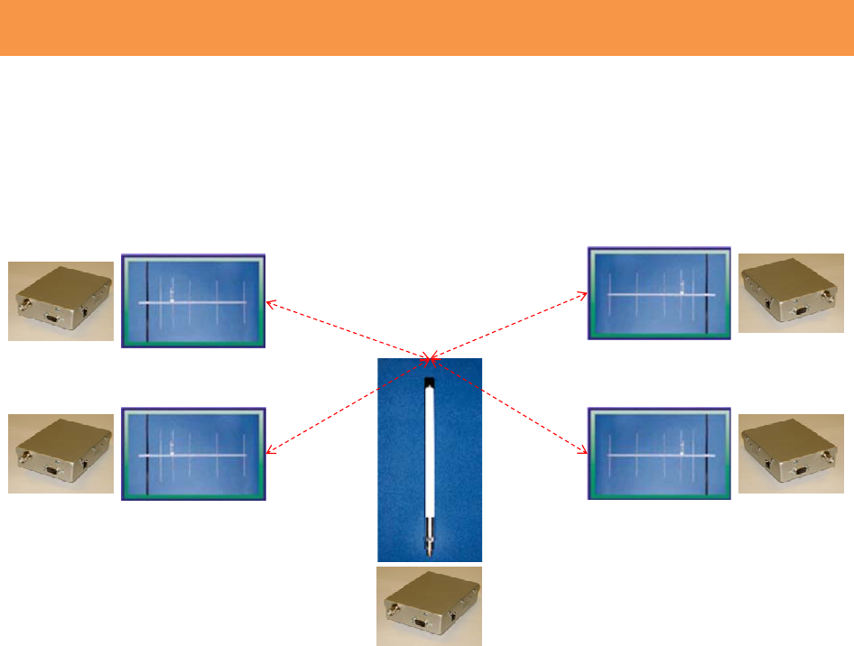
ThemostcommonapplicationfortheVTRisa‘star’networkwhereasinglehubsite
communicatestoacollectionorremotesitesasshowninFigure2.1.
Hub
Radio
Remote
Radios
Remote
Radios
Figure2.1:StarNetworkConfiguration
TheHubVTRisconnectedtoanomnidirectionalantennaviaalengthofcoaxialcable.The
signaltransmittedbytheHubVTRistransmittedina360‐degreepatterntoallremotesites
withinarangesupportedbytheconfiguredtransmittedpower.EachremotesiteVTRis
typicallyconnectedtoadirectionalantennaviaalengthofcoaxialcable.Theseantennasare
‘pointed’towardtheHubtoachievemaximumgain.
Radioscanbeconfiguredtooperateintwomodes.Mode1isselectedwhentheVTRisto
emulatethecurrentT‐200radioandoperateat2.4kb/susingacompatiblewaveform.The
VTRinthismodeisinterchangeablewiththeT‐200andthereisnodifferenceintheoperation
ofHubandRemoteconfigurations.AllVTRsinaMode1networkshouldbeconfiguredasa
Remote.InMode1,onlytheSerialPortisusedtoexchangedatawiththeuserdeviceandthe
portspeedis2.4kb/s.
InMode2,VTRsmustbeconfiguredasaHuborRemote.TheHubVTRwillacceptuser
messagesovertheEthernetLANPort.TheseareASCII‐formattedmessageswithrecognized
SOMandEOMcharactersthatareencapsulatedinIPpackets.TheHubuserdevicewilladdress
thesetotheconfiguredRadioIPAddress.TheMode2RemoteVTRwillexchangeuserdata
overtheserialport.UsermessageswillberemovedfromtheIPPacketsandsenttothelocal
userdeviceovertheserialport.
AllmessagessentbytheHubVTRwillbeforwardedtotheserialportsofallVTRs.

3.0Specifications
Electrical
Frequency bands
Low Band 145 to 225 MHz
Mid Band 225 to 470 MHz
High Band 470 to 930 MHz
RF Transmit Power 17 to 32 dBm
Noise Figure 4 dB
Spurious & Harmonic Emissions FCC Part 15 & 90 compliant
Data Rates 2.4 to 34 kb/s
Channel Bandwidths 12.5, 25 or, 50 kHz
Modulation 2-FSK
Frequency Selection 12.5 kHz steps
Operating mode Burst, Time-division duplexing
Microprocessor Freescale i.MX27, 400 MHz
Processor Memory
RAM 32 MB
FLASH 2 MB
Modem FPGA Memory 1 MB
Mechanical
Dimensions 3.5” x 5.0”x1.4”
Enclosure material AL, clear anodized finish
Weight (wall mount) 300 g
Mounting table-top or wall
Environmental
Operating Temperature Range -30 to 550 C
Operating Humidity Up to 95%, non-condensing
Power
Input Voltage 9 to 14 VDC
Consumption
Transmit 1.5 A
Receive 0.5 A
Specifications subject to change without notice.