Data Sciences TMS2 Small Animal Implant Transmitter User Manual 4ET for FCC
Data Sciences International Inc Small Animal Implant Transmitter 4ET for FCC
Users Manual

4ET Telemetry User Guide

Acknowledgments
Dataquest, the DSI Logo, and PhysioTel are registered trademarks of Transoma Medical in the
United States and certain other foreign countries.
A.R.T. is a trademark of Transoma Medical.
4ET Telemetry User Guide
Reorder Number XXX-XXXX-XXX
Revision 01
Copyright Transoma Medical 2006
All Rights Reserved
Printed in U.S.A.
Data Sciences International (DSI)
4211 Lexington Ave. N • Suite 2244 • St. Paul, MN 55126
Telephone: (1-651) 481-7400 • 800-262-9687
Fax: (1-651) 481-7415
Web Site: http://www.datasci.com
Table of Contents
Theory of Operation...........................................................Error! Bookmark not defined.
Specifications................................................................................................................ 1
Naming Convention .................................................................................................................... 1
Part Numbers.............................................................................................................................. 2
General Specifications................................................................................................................ 2
Dimensions .................................................................................................................................3
FCC Compliance Statement....................................................................................................... 4
Setup .............................................................................................................................. 4
Product Use ................................................................................................................................ 4
Matching Repeaters with Repeater Receivers..........................Error! Bookmark not defined.
Software Setup ..........................................................................Error! Bookmark not defined.

Theory of Operation
The 4ET is a Physiotel® transmitter that will allow measurement of four different
biopotential readings. Included in these measurements but not limited are EOG, EMG,
ECG and EEG. This transmitter also has the capability to monitor from multi-housed
animals. The signal from this transmitter can be manufactured to broadcast over one of
two different frequencies. The new frequencies accommodate more channels and higher
bandwidth. These new features also accommodate more flexibility for study design than
the standard DSI transmitters.
There are two different frequencies that can be used with this transmitter, allowing two
animals to be housed together while simultaneously collecting data from each animal.
The other option would be to house single animals closer together without the worry of
crosstalk.
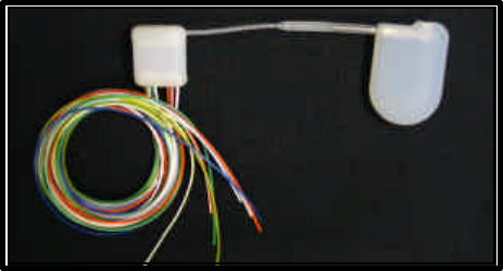
Use of this transmitter begins with implanting the different components of the
transmitter. Unlike other standard transmitters from DSI the 4ET has two housing units
with an IS-1 connector to make up the entire transmitter. The leads are attached to the
housing unit that is termed as the sensing unit. The battery is housed in the telemetry unit
along with the signal relay components. The transmitter is designed to accommodate the
option of replacing the telemetry unit without removing the sensing unit. Since there are
two different frequencies it will be important to note the frequencies that are implanted in
animals.
The receiver that is compatible with this transmitter is the RPC-2. This receiver has the
ability to collect from two different frequencies simultaneously. There are two carrier
lights, two power lights, two cables and takes up two slots on DQ ART. When pair
housing the animals you will need a spacer in between the receiver and the animal’s cage.
Specifications
Naming Convention
The 4ET model name, for example H4ET-S1, is defined by the following:
The first alpha value is indicating if it is hermetic: H4ET-S1
H = Hermetic
No letter = Non-hermetic
The next alpha-numeric value is indicative of the transmitter type: H4ET-S1
4E = four biopotential channels
T = temperature channel
The last alpha-numeric value represents size and frequency of transmitter: H4ET-S1:
S1 = small animal, frequency 1

S2 = small animal, frequency 2
L1 = large animal, frequency 1
L2 = large animal, frequency 2
Part Numbers
Presently there are two sizes of 4ET transmitters available:
4ET (Small animal) H4ET (Large animal)
Frequency 1 270-0142-001 4ET–S1 270-0140-001 H4ET–L1
Frequency 2 270-0142-002 4ET–S1 270-0140-002 H4ET–L2
** Part numbers for the 4ET and H4ET include both the sensing module and telemetry
module. For a telemetry replacement module only see table below.
Replacement parts:
Telemetry Module
Small animal Large Animal
Frequency 1 270-0141-001 TM–S1 270-0139-001 TM–L1
Frequency 2 270-0141-002 TM–S2 270-0139-002 TL–L2
General Specifications
Small Animal Large Animal
Physical
Weight/mass (gm) 23.4
Volume (cc) 8.66 12
Minimal animal
Weight 175 gm
IS-1 lead length 6.5cm (2.5 inches) 6.5cm (2.5 inches)
Biopotential lead length 50 cm 50 cm
On – Off mechanism Magnetically Actuated Magnetically Actuated
Receiver compatibility RPC-2 Repeater System
Electrical
Max input voltage + 1.25 mV + 1.25 mV
Bandwidth 1-100 Hz 1-100Hz
Transmission distance
Battery Specifications
Battery life 3 months 6 months
Warranted Implant Duration
Sensing module
warranted implant 3 years 3 years
Telemetry module
warranted implant 1 year 1 year
Environmental
Operating
Temperatures (Celsius) 34 – 41 34 – 41
Other
Refurbishable No No
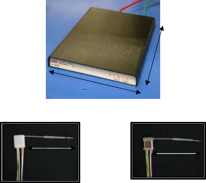
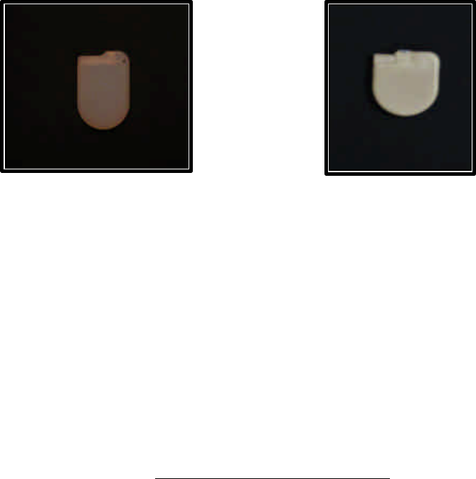
Dimensions
Below are drawings that give dimensions of RPC-2, sensing and telemetry module:
Fig 1. RPC -2 Receiver
Sensing Module
Fig. 2 Non – Hermetic Fig. 3 Hermetic
328 mm
227 mm + 2 mm
IS
-
1 Lead
(2.5
“
)
IS
-
1 Lead
(2.5
“
)
Telemetry Module
Fig. 4 SA Telemetry Module Fig. 5 LA Telemetry Module
FCC Compliance Statement
This device complies with Part 15 of the FCC rules and Industry Canada RSS 210. Operation is
subject to the following two conditions: (1) This device may not cause harmful interference and
(2) this device must accept any interference that may cause undesired operation.
Caution:
Changes or modifications not expressly approved by the party responsible for compliance could void the
users authority to operate the equipment.
FCC and Industry Canada (IC) ID
FCC IC IC ID
4ET SA 8MHz Implant FCCID:MHATMS1 IC:5681A-MHATMS1
4ET SA 18MHz Implant FCCID:MHATMS2 IC:5681A-MHATMS2
4ET LA 8MHz Implant FCCID:MHATML1 IC:5681A-MHATML1
4ET LA 18MHz Implant FCCID:MHATML2 IC:5681A-MHATML2
Setup
Product Use
Sensing Module:
o Portion of the transmitter that collects the data from the animal.
• Channel 1 Blue (internal ground)
• Channel 2 Orange
• Channel 3 Green
• Channel 4 Yellow
o Positive Lead: Solid
o Negative Lead: Solid + White Stripe
o Implant channels 1 and 3 using the most stable signals (low baseline
wander)
• These channels are shared with other parameters (temperature,
battery, voltage, ground) that could become inaccurate with excess
wander from biopotential.
• DSI suggests using channels 1 and 3 for EEG or EMG
Telemetry Module:
o Portion of the transmitter that transmits the data to the receiver. This also
is designed to be replaceable since it houses the battery as well. The IS-1
lead is also connected to this module with the ability to disconnect the IS-
1 from the sensing module and replace the telemetry module. This
module is also houses the frequency designation that is broadcasted to the
receiver.
o Can be in two different modes: free-run and normal. Free-run mode is the
ability to turn on the telemetry module without having the sensing module
attached. The tone heard should be lower than the normal mode. Normal
mode is the mode needed to be in to collect data.
Matching Transmitter with RPC-2 Receiver
The 4ET SA transmitter must be used with the RPC-2 receiver regardless if
animals are pair or single housed. It will have two Ethernet cables coming out the back
of the receiver to the matrix as seen in figure 1. Two jacks on the data exchange matrix
will also be needed. Consequently this means that there will be two sampling slots
needed in the software even though there is only one receiver. It will be necessary to
connect both cables coming from the same RPC-2 receiver into the same matrix.
However it won’t be necessary to connect the cables in adjacent jacks. The two carrier
lights on the front of the receiver will be indicative of which signal is being picked up.
The two power lights on the front will be illuminated when the receiver is getting power
for both frequencies to be detected.
The RPC-2 receiver can be used to monitor from one animal or two animals. If
monitoring from two animals it will be necessary to house two animals with different
frequencies. Additionally with pair housed animals a 2.5” spacer is needed in between
the receiver and the cage to avoid crosstalk between the animals. This spacer will be
included with the purchase of an RPC-2. When animals are paired housed the RPC-2
receivers are going to need further separation between receivers, about 30 inches should

sufficient. The other option would be to individually house the animals. Animals housed
individually will be able to have the cages closer together and there will be no need for a
spacer.
Software Setup
Setup of the 4ET transmitter with the Dataquest ART system will be a tedious process.
Keeping track of all the information on the transmitters and where they are implanted and
what receiver they are being placed on will be crucial in making this process go
smoothly. There is a log at the back of this manual that will aid in the organization of
setting up the transmitters.
Configuring the RPC-2
The RPC-2 receiver will be detected automatically by the software just as the
RMC and RPC receivers do. Once the RPC-2 receiver has been detected by the computer
it will show up as two different receivers with two names:
• RPC-2 F1 SN XXX
• RPC-2 F2 SN XXX
The F1 and F2 are referring to the 4ET frequency that is being detected. F1 is referring
to the 8 MHz channel and the F2 is referring to the 18 MHz channel.
If there is only going to be one transmitter on a receiver then it won’t be necessary to
configure anything on the receiver for the channel that is not being used.
Configuring the 4ET transmitter
Follow the listed steps to get the 4ET transmitter configured properly:
1. If using the 4ET with the Dataquest ART 4.0 there is a patch that will be needed.
All software previous to Dataquest ART 4.0 is not compatible with the 4ET
transmitter. Any software following Dataquest ART 4.0 will be compatible with
the transmitter without an additional patch.
2. All the transmitters that are using the 8 MHz frequency will need to be configured
on the F1 receivers. The 18 MHz frequency transmitters will need to be
configured on the F2 receivers.
3. After the appropriate receiver has been chosen then select to add a new
transmitter to the particular receiver. The 4ET transmitter will be listed as 4ET
S1 or 4ET S2. (Whether using hermetic sensing module or not)
4. A number of calibration values will need to be entered at this time as well as the
signal type used for each channel. There are no limitations regarding what signal
can be detected from each channel. DSI however does have two suggestions: for
channels 1 and 3 use a more stable signal, for example the EMG or EEG. The
other suggestion is if using this smaller transmitter in a larger animal to detect
ECG the lead placement would be best closer together, since the input voltage
range for the channel is + 1.25 mV.
5. Following the manual configuration of the transmitters you can close the
configuration hardware window and return to the acquisition window. Before you
start sampling from the animals you will want to be sure the transmitters are
turned on by using the radio provided. Use the S1 channel to monitor the 8 MHz
transmitters and the S2 channel to monitor the 18 MHz transmitters.