Datalogic ADC PWRSCAN-BS Powerscan RF Base Station User Manual
Datalogic ADC, Inc. Powerscan RF Base Station
UserManual.wiki
>
Datalogic ADC
>
PWRSCAN BS User Manual
R44 114 manual
Navigation menu
Upload a User Manual
Namespaces
Wiki Guide
HTML
PDF
Info
Views
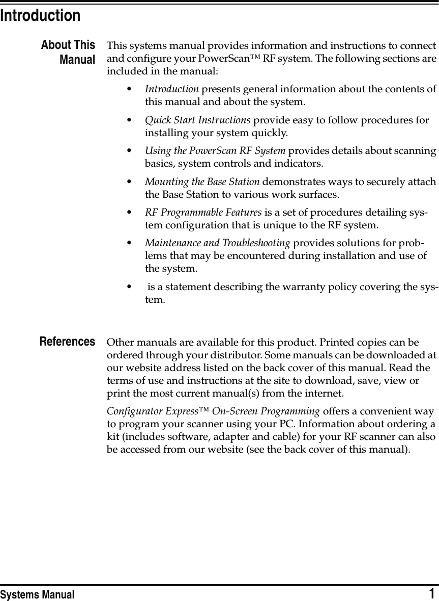
User Manual
Discussion / Help
Navigation


![Asia PacificPSC Hong KongHong KongTelephone: [852]-2-584-6210Fax: [852]-2-521-0291AustraliaPSC Asia Pacific Pty Ltd.North Ryde, AustraliaTelephone: [61] 0 (2) 9878 8999Fax: [61] 0 (2) 9878 8688FrancePSC SarlLES ULIS Cedex, FranceTelephone: [33].01.64.86.71.00Fax: [33].01.64 46.72.44GermanyPSC GmbHDarmstadt, GermanyTelephone: + 49 (0) 61 51/93 58-0Fax: + 49 (0) 61 51/93 58 58ItalyPSC S.r.l.Vimercate (MI), ItalyTelephone: [39] (0) 39/62903.1Fax: [39] (0) 39/685496JapanPSC Japan K.K.Shinagawa-ku, Tokyo, JapanTelephone: 81 (0)3 3491 6761Fax: 81 (0)3 3491 6656Latin AmericaPSC S.A., INC.Miami, Florida, USATelephone: (305) 539-0111Fax: (305) 539-0206United KingdomPSC Bar Code Ltd.Watford, EnglandTelephone: 44 (0) 1923 809500Fax: 44 (0) 1923 809 505Corporate Headquarters675 Basket RoadWebster, NY 14580-9787Telephone: (716) 265-1600Fax: (716) 265-6400PSC Scanning, Inc.959 Terry StreetEugene, OR 97402-9150Telephone: (541) 683-5700Fax: (541) 686-1702Printed on recycled paperwww.pscnet.com©2000 PSC INC. R44-2114 (Rev. C) Printed in USA (11/00)](https://usermanual.wiki/Datalogic-ADC/PWRSCAN-BS/User-Guide-127680-Page-88.png)