Datalogic S r l 0022 915MHz radio module User Manual
Datalogic ADC S.r.l. 915MHz radio module
Contents
User Manual

Author: Radio Group
Date: February 11th, 2014
Revision: March 4th, 2015
Subject: Integration Guide – Mizar Radio Module 915 MHz
Page 1 of 10
Integration Guide
Mizar Radio Module 915 MHz

Author: Radio Group
Date: February 11th, 2014
Revision: March 4th, 2015
Subject: Integration Guide – Mizar Radio Module 915 MHz
Page 2 of 10
Table of contents
Document history ...................................................................................................... 3
Regulatory:................................................................................................................. 4
Introduction ............................................................................................................... 6
Pinout ........................................................................................................................ 6
Block diagram ............................................................................................................ 6
Antennas.................................................................................................................... 7
Operational description ............................................................................................. 7
Working modes.............................................................................................................................................. 7
Functional states ........................................................................................................................................... 7
Idle State.................................................................................................................................................... 7
Receive State ............................................................................................................................................. 7
Transmission State..................................................................................................................................... 8
Interface description (pinout reference) .................................................................... 8
Electrical characteristics............................................................................................. 9
RF characteristics ....................................................................................................... 9
Low speed mode............................................................................................................................................ 9
High speed mode ......................................................................................................................................... 10

Author: Radio Group
Date: February 11th, 2014
Revision: March 4th, 2015
Subject: Integration Guide – Mizar Radio Module 915 MHz
Page 3 of 10
Document history
Date
Author
Notes
April 19th, 2012
Davide Carli
Initial draft
May 2nd, 2012
Davide Carli
Added details on test command(s) 0x86
May 31th, 2012
Davide Carli
In-depth documentation of test commands
July 18th, 2012
Davide Carli
Added data on current consumption in DEEP SLEEP status
April 15th, 2013
Davide Carli
Updated the description of some test commands
December 20th, 2013
Davide Carli
Document splitted in 433 MHz and 915 MHz versions
RF Characteristics updated according to FW 2.01A and 2.01B
Removed outdated information
January 15th, 2014
Davide Carli
RF Characteristics updated according to FW 2.02B
February 11th, 2014
Pier Giorgio Peruzzi
Added Operational description and Interface description

Author: Radio Group
Date: February 11th, 2014
Revision: March 4th, 2015
Subject: Integration Guide – Mizar Radio Module 915 MHz
Page 4 of 10
Regulatory
FCC regulation
Interference warning
This device complies with Part 15 of the FCC Rules. Operation is subject to the following two conditions:
1. This device may not cause harmful interference, and
2. This device must accept any interference received, including interference that may cause undesired operation.
Any change or modification to the product not expressly approved by Datalogic ADC S.r.l. could void the user' s
authority to operate the device.
FCC RF Radiation Exposure Statement
To comply with FCC RF exposure compliance requirements, for mobile configurations, a separation distance of at least
20 cm must be maintained between the antenna of this device and all persons. This device must not be co-located or
operating in conjunction with any other antenna or transmitter
Antennas
This radio transmitter may only operate using the antennas certified as listed in this document at Clause “Antenna”.
Industry Canada regulation
Under Industry Canada regulations, this radio transmitter may only operate using an antenna of a type and maximum
(or lesser) gain approved for the transmitter by Industry Canada. To reduce potential radio interference to other users,
the antenna type and its gain should be so chosen that the equivalent isotropically radiated power (e.i.r.p.) is not more
than that necessary for successful communication.
Conformément à la réglementation d'Industrie Canada, le présent émetteur radio peut fonctionner avec une antenne
d'un type et d'un gain maximal (ou inférieur) approuvé pour l'émetteur par Industrie Canada. Dans le but de réduire les
risques de brouillage radioélectrique à l'intention des autres utilisateurs, il faut choisir le type d'antenne et son gain de
sorte que la puissance isotrope rayonnée équivalente (p.i.r.e.) ne dépasse pas l'intensité nécessaire à l'établissement
d'une communication satisfaisante
and:
This radio transmitter (identify the device by certification number, or model number if Category II) has been approved
by Industry Canada to operate with the antenna types listed below with the maximum permissible gain and required
antenna impedance for each antenna type indicated. Antenna types not included in this list, having a gain greater than
the maximum gain indicated for that type, are strictly prohibited for use with this device.

Author: Radio Group
Date: February 11th, 2014
Revision: March 4th, 2015
Subject: Integration Guide – Mizar Radio Module 915 MHz
Page 5 of 10
Le présent émetteur radio (identifier le dispositif par son numéro de certification ou son numéro de modèle s'il fait
partie du matériel de catégorie I) a été approuvé par Industrie Canada pour fonctionner avec les types d'antenne
énumérés ci-dessous et ayant un gain admissible maximal et l'impédance requise pour chaque type d'antenne. Les
types d'antenne non inclus dans cette liste, ou dont le gain est supérieur au gain maximal indiqué, sont strictement
interdits pour l'exploitation de l'émetteur.
RF Radiation Exposure Statement
To comply with IC RF exposure compliance requirements, for mobile configurations, a separation distance of at least 20
cm must be maintained between the antenna of this device and all persons. This device must not be co-located or
operating in conjunction with any other antenna or transmitter
Exposition aux radiations RF
Afin de se conformer avec les exigences de conformité de l'exposition RF, pour des configurations mobiles, une distance
de séparation d'au moins 20 cm doit être maintenue entre l'antenne de cet appareil et toutes les personnes. Ce
dispositif ne doit pas être co-située ni fonctionner en conjonction avec une autre antenne ou transmetteur
Antennas
This radio transmitter (MIZAR Radio Module 915MHz) has been approved
by Industry Canada to operate with the antenna types listed below. Antenna types not included in this list, having a gain
greater than
the maximum gain indicated for that type, are strictly prohibited for use with this device.
Antennes
Cet émetteur radio (Radio MIZAR Module 915MHz) a été approuvé par Industrie Canada pour fonctionner avec les
types d'antenne énumérés ci-dessous. Types d'antennes pas figurent dans cette liste, ayant un gain supérieur à le gain
maximum indiqué pour ce type, sont strictement interdites pour une utilisation avec cet appareil.
Author: Radio Group
Date: February 11th, 2014
Revision: March 4th, 2015
Subject: Integration Guide – Mizar Radio Module 915 MHz
Page 6 of 10
Introduction
Mizar radiofrequency (RF) module operates in the 902-928 MHz ISM frequency band.
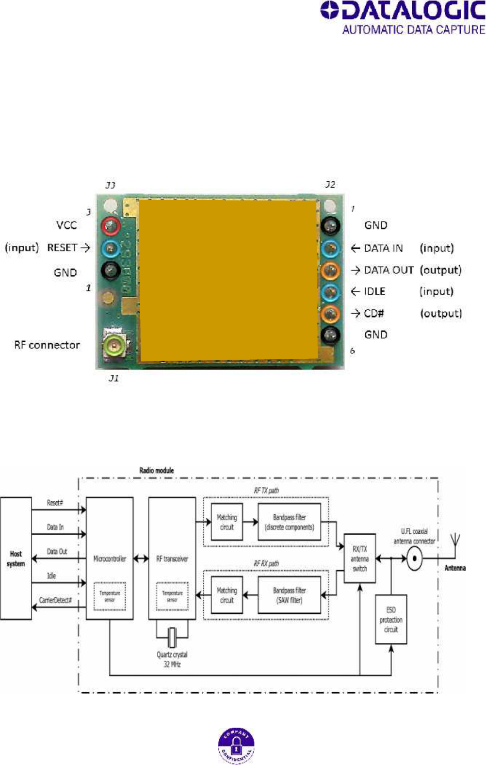
Pinout
Block diagram

Author: Radio Group
Date: February 11th, 2014
Revision: March 4th, 2015
Subject: Integration Guide – Mizar Radio Module 915 MHz
Page 7 of 10
Antennas
The module has been approved with the antennas listed below:
Datalogic, part number 663316020 – 902-928 MHZ Helical Antenna – gain 1dBi, impedance 50Ω
Antenna Factor, model ANT-916-CW-QW – gain 3dBi, impedance 50Ω
Bondale Electronics, model G-RA0K14155047 – gain 1dBi, impedance 50Ω
Datalogic, part number ANTENNA CABLE GM4100-910 – gain -4,5dBi, impedance 50Ω
Operational description
The equipment is a radio module to be integrated inside cordless devices.
It is based upon an FSK ( Frequency Shift Keying Modulation ) Half-Duplex transceiver working in the ISM
band from 902 to 928 MHz.
The radio module has a UART interface to exchange data and commands.
Working modes
Radio module can operate in the follow working modes :
Low Speed, Low Power, fixed channel (among 25 channels)
oFSK, Bitrate 36864 bps, RZ Manchester encoded, Frequency deviation +/- 75KHz
Low Speed, Frequency Hopping Mode over 25 channels
oFSK, Bitrate 36864 bps, RZ Manchester encoded, Frequency deviation +/- 75KHz
High Speed, Digital Transmission Mode, fixed channel (among 12 channels)
oFSK, Bitrate 500,000 bps, NRZ, Frequency deviation +/- 220KHz
High Speed, Digital Transmission + frequency agility Mode over 12 channels
oFSK, Bitrate 500,000 bps, NRZ, Frequency deviation +/- 220KHz
Default mode after power-up is Low Speed Low Power mode.
Radio module can receive commands to allow to change its working mode.
Functional states
Radio module can be set in one of the following states during operation:
Idle State
Radio module stays in low power receiving mode with a limited capability to receive data. RF transmission
is not allowed while radio is set in Idle state.
Receive State
It is the normal default state. In this state the radio receives the RF packets, decodes the packets and sends
them to the Host device. In this mode the transceiver checks continuously the RF signal and demodulates
it. The demodulated and filtered signal is sent to the microcontroller inside the radio module which

Author: Radio Group
Date: February 11th, 2014
Revision: March 4th, 2015
Subject: Integration Guide – Mizar Radio Module 915 MHz
Page 8 of 10
decodes it and sends decoded data to the Host by means of the UART interface. Only valid demodulated
data packets are sent to the Host.
Transmission State
This state is enabled from the host when it needs to transmit data. The transmission state is enabled
sending a data packet to the radio module over the UART interface. The microcontroller in the radio
module checks for the integrity of the data packet and enables the transceiver to modulate and transmit to
the RF interface, preceded by a short preamble burst. Radio module exits automatically from this state
when the complete packet has been transmitted, and returns to the receive state.
Radio module operates in CSMA-CA (carrier sense multiple access – collision avoidance) : transmission is
enabled when the RF channel is not busy by the use of a “carrier detect” function. Radio module accesses
the channel in a fair way using a backoff algorithm.
Interface description (pinout reference)
UART 2-pin interface, used to exchange data from the Host:
DATA_OUT (output pin) : transmits data to Host.
DATA_IN (input pin) : receives data from Host.
CD# – (output pin) Carrier Detect :
When radio is in receive mode, this pin signals the presence of RF carrier.
IDLE - (input pin) :
A high level on this pin forces the radio module in Idle State.
RESET (input pin) :
A low level on this pin resets the radio module.
VCC and GND :
Radio module power supply.
RF Port :
Radio Frequency Connector for the antenna.
Author: Radio Group
Date: February 11th, 2014
Revision: March 4th, 2015
Subject: Integration Guide – Mizar Radio Module 915 MHz
Page 9 of 10
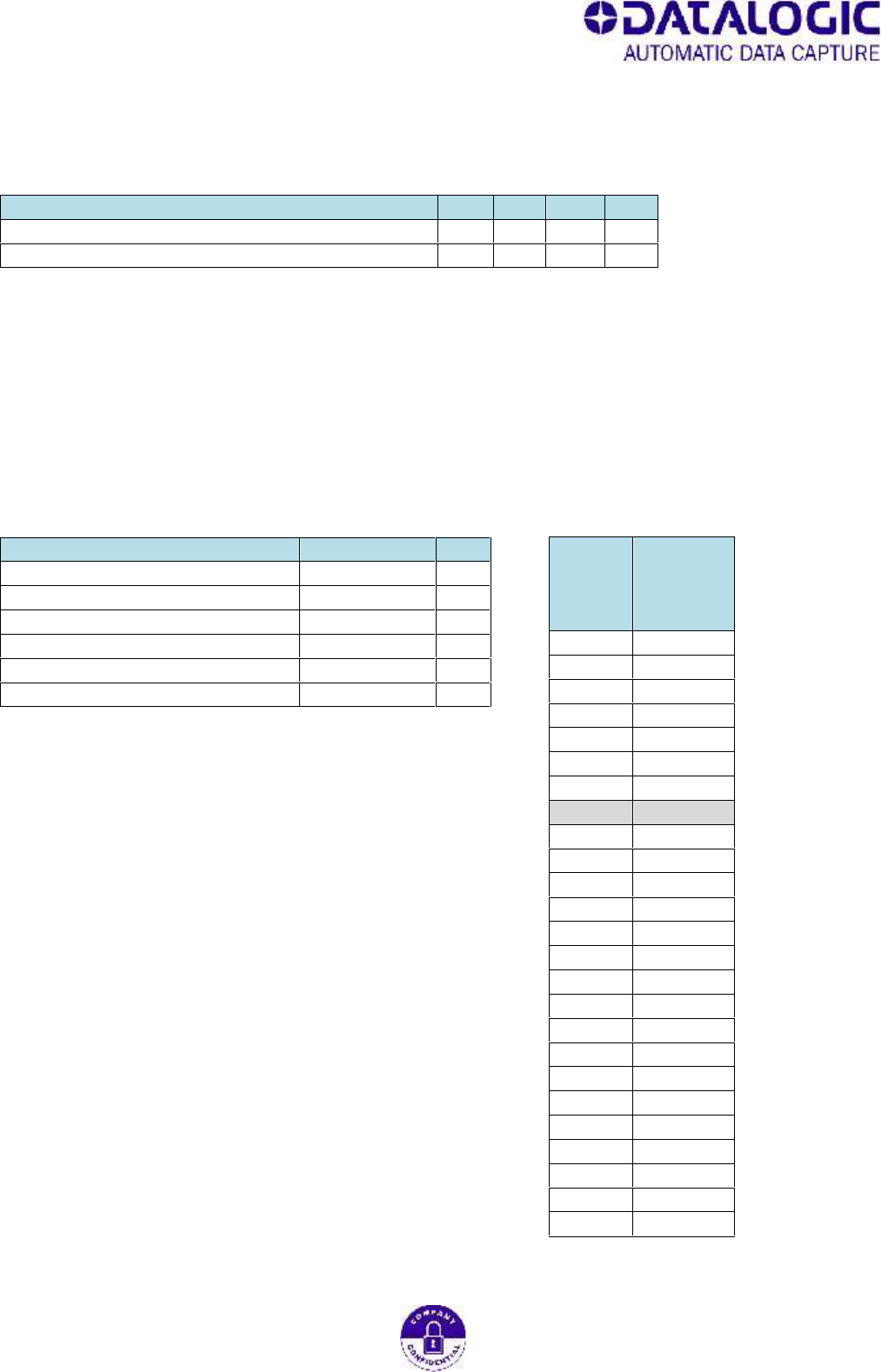
Electrical characteristics
Table 1
Parameter
Min.
Typ.
Max.
Unit
Power supply voltage (between VCC pin and GND pin)
3,1
3,3
3,6
V
Operating temperature range
-30
---
+85
°C
RF characteristics
Low speed mode
Table 2
Parameter
Typ. value
Unit
Modulation
RZ Manchester
Bit rate (over-the-air)
36864
bit/s
Frequency deviation
± 75,000
kHz
Number of supported channels
25
Index of default channel
8
Center frequency of default channel
910,00000
MHz
Table 3
Channel
index
Channel
center
frequency
[MHz]
1
902,80050
2
903,82900
3
904,85750
4
905,88600
5
906,91450
6
907,94300
7
908,97150
8
910,00000
9
911,02850
10
912,05700
11
913,08550
12
914,11400
13
915,14250
14
916,17100
15
917,19950
16
918,22800
17
919,25650
18
920,28500
19
921,31350
20
922,34200
21
923,37050
22
924,39900
23
925,42750
24
926,45600
25
927,48450
Author: Radio Group
Date: February 11th, 2014
Revision: March 4th, 2015
Subject: Integration Guide – Mizar Radio Module 915 MHz
Page 10 of 10
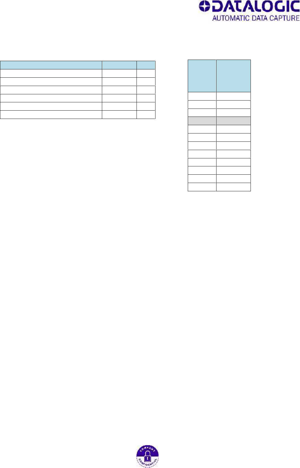
High speed mode
Table 6
Parameter
Typ. value
Unit
Modulation
NRZ
Bit rate (over-the-air)
500000
bit/s
Frequency deviation
± 220,000
kHz
Number of supported channels
12
Index of default channel
4
Center frequency of default channel
910,00000
MHz
Table 7
Channel
index
Channel
center
frequency
[MHz]
1
903,64900
2
905,76600
3
907,88300
4
910,00000
5
912,11700
6
914,23400
7
916,35100
8
918,46800
9
920,58500
10
922,70200
11
924,81900
12
926,93600