Datalogic S r l 0030 POCKET-SIZED MOBILE COMPUTER User Manual DL Memor master
Datalogic ADC S.r.l. POCKET-SIZED MOBILE COMPUTER DL Memor master
UserManual.wiki
>
Datalogic S r l
>
0030 User Manual
Users Manual
Navigation menu
Upload a User Manual
Namespaces
Wiki Guide
HTML
PDF
Info
Views
User Manual
Discussion / Help
Navigation

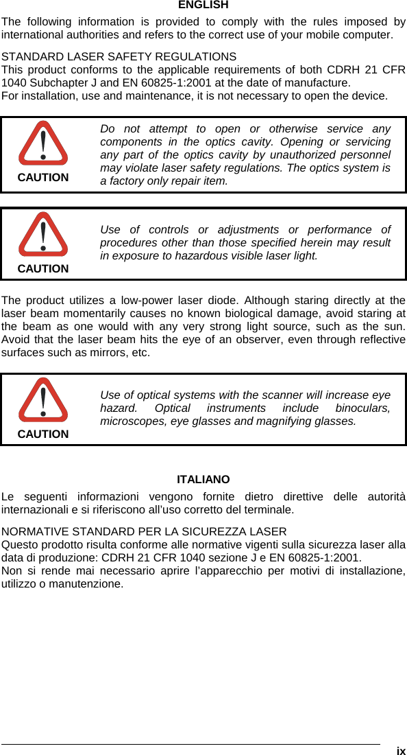
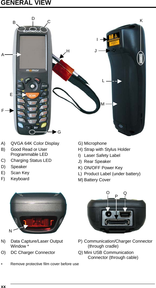
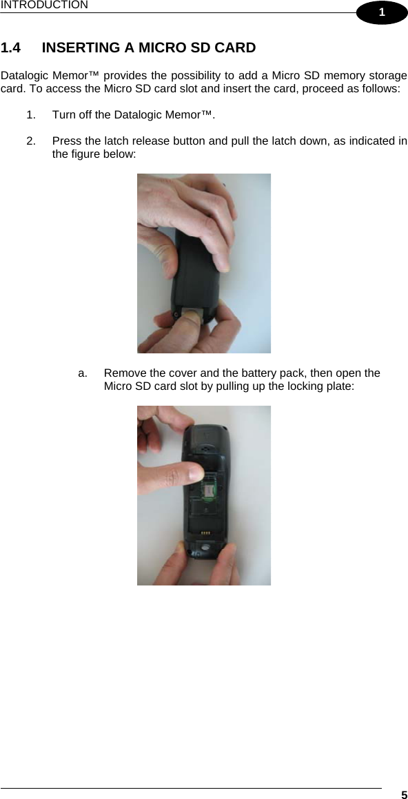


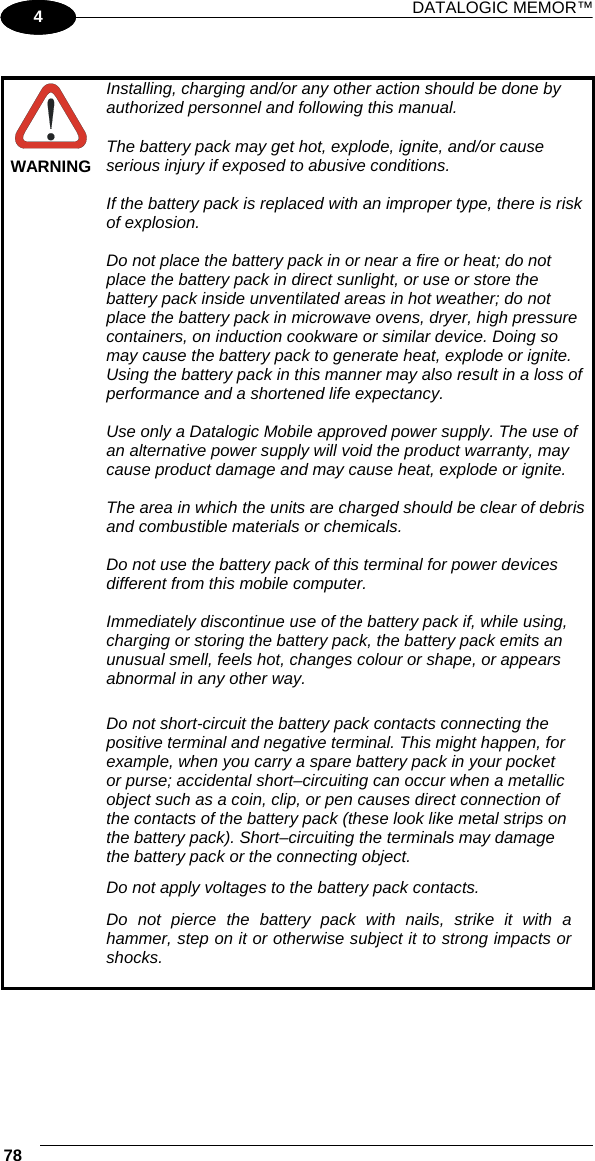
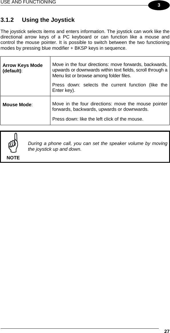
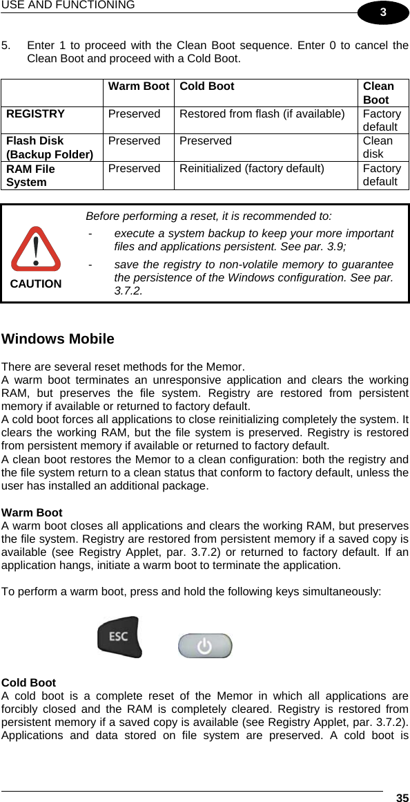
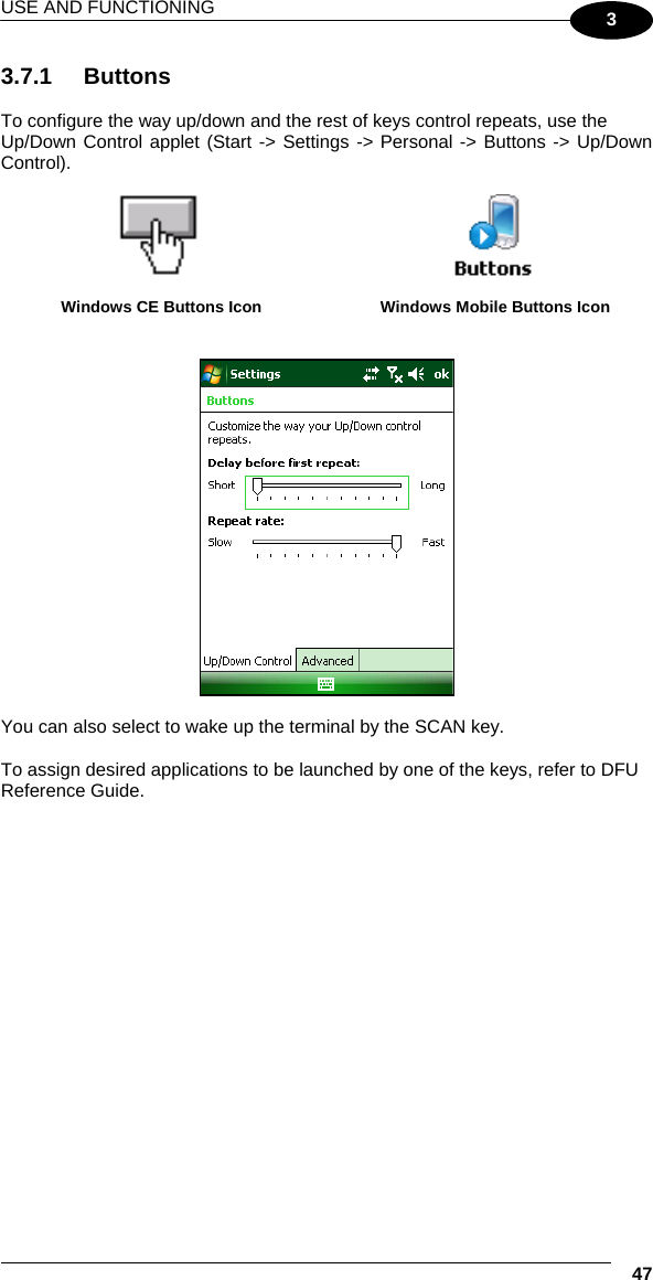
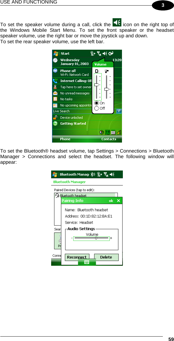
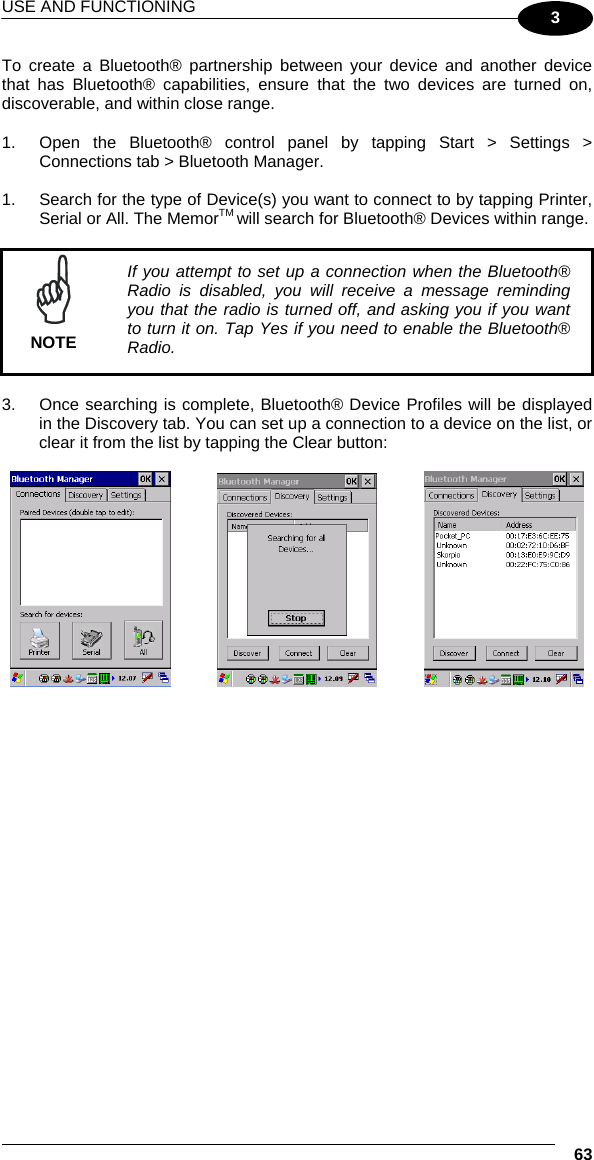
![DATALOGIC MEMOR™ 24 1 3 3 USE AND FUNCTIONING The use of the Datalogic Memor™ depends on the application software loaded. However there are several parameters that can be set and utilities that can be used to perform some basic functions such as data capture, communications, file management, etc. 3.1 STARTUP The Datalogic Memor™ turns on when the battery pack or the external supply is inserted. After the battery pack is installed, use the [ON/OFF] key to turn the mobile computer on and off. As soon as the mobile computer is on, the Windows CE 5.0/ Windows Mobile desktop configuration will appear on the screen. Wait a few seconds before starting any activity so that the mobile computer completes its startup procedure. Windows CE Desktop Windows MobileToday Screen Use the stylus (par. 3.1.1) or joystick (par. 3.1.2) as suggested to select icons and options. The mobile computer goes into power-off (low power with display and keyboard backlight off), when it is no longer used for more than a programmable timeout, which is defined in the POWER applet of the Control Panel. In this mode it can be awakened (resuming operation) by the [ON/OFF] key.](https://usermanual.wiki/Datalogic-S-r-l/0030/User-Guide-1129715-Page-44.png)
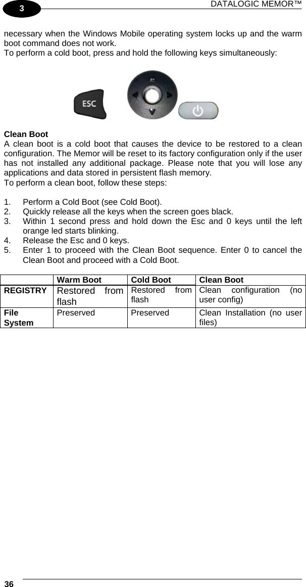
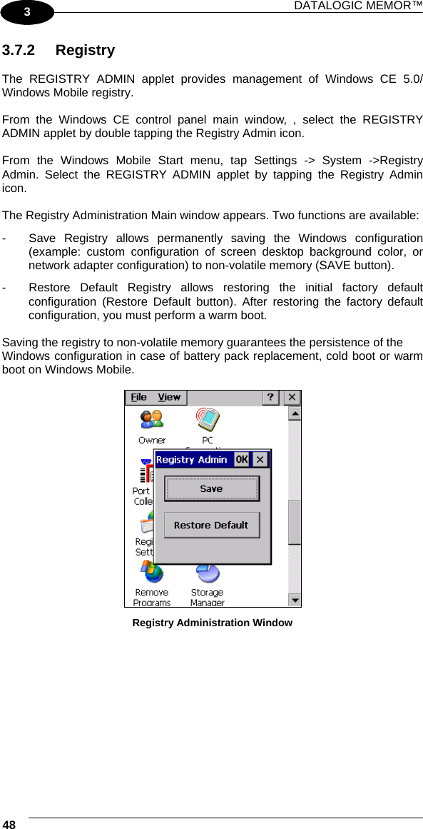
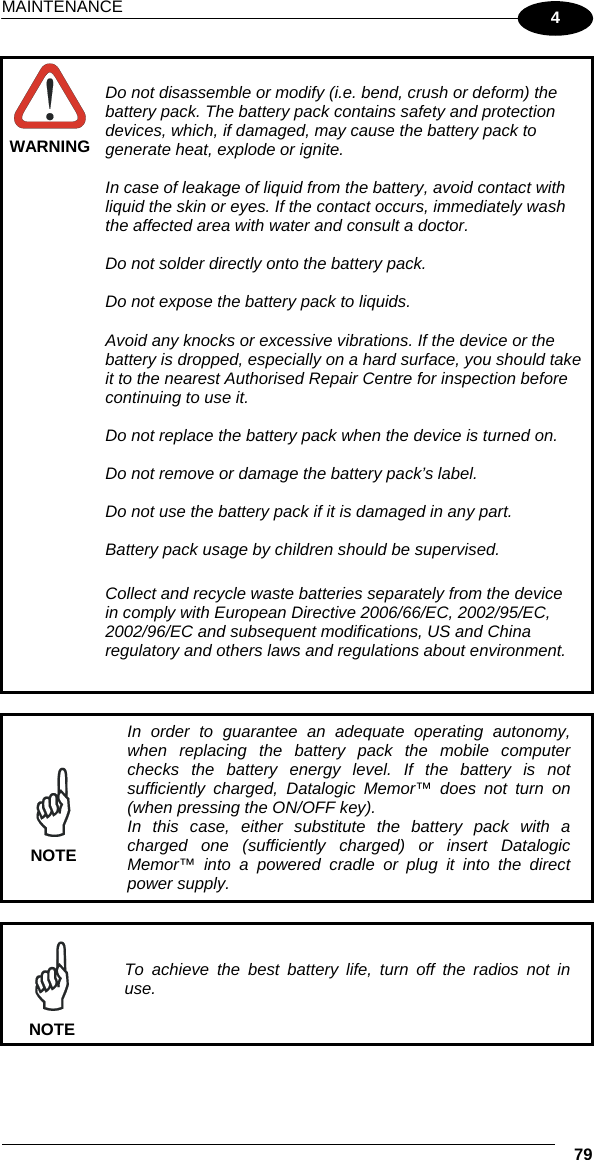
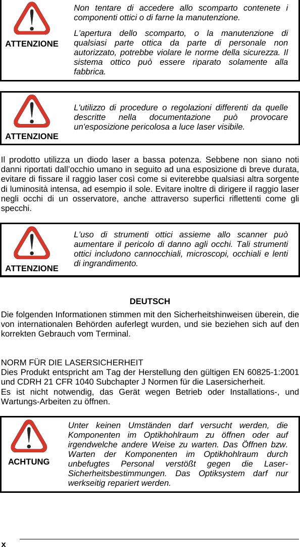
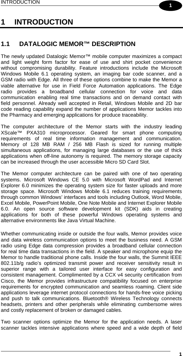
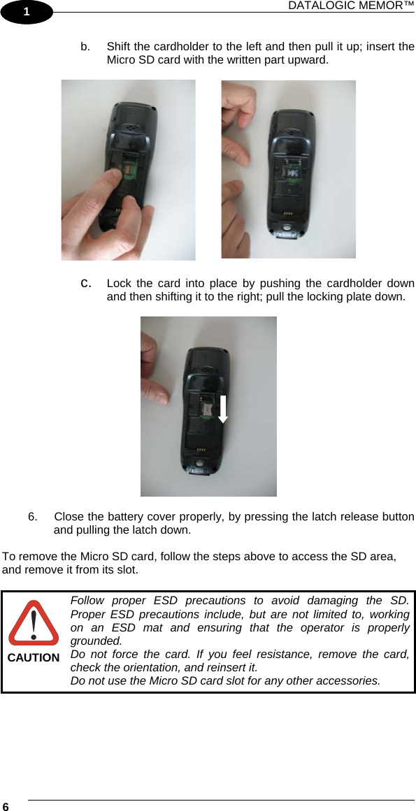
![DATALOGIC MEMOR™ 72 1 3 3.8.4 FTP Server Setup The Datalogic Memor™ Windows CE Operating System includes a sample File Transfer Protocol (FTP) server. FTP is used for copying files to and from remote computer systems over a network using TCP/IP. You can establish a connection to your Datalogic Memor™ using its FTP Server through the following interfaces: WLAN using the 802.11b/g radio Proceed as follows: 1. Create a registry file (extension .reg) to setup and enable FTP Server communication. A simple example file for anonymous logon is given below: REGEDIT4 [HKEY_LOCAL_MACHINE\Comm\FTPD] "DefaultDir"="\\" "AllowAnonymousUpload"=dword:00000001 "UseAuthentication"=dword:00000000 "BaseDir"="\\" "IsEnabled"=dword:00000001 "LogSize"=dword:00001000 "DebugOutputMask"=dword:00000017 "DebugOutputChannels"=dword:00000002 "IdleTimeout"=dword:0000012c "AllowAnonymous"=dword:00000001 "AllowAnonymousVroots"=dword:00000001 2. Copy this file to the Datalogic Memor™ using ActiveSync®. 3. Launch the .reg file from the Datalogic Memor™. 4. Perform a warm boot on the Datalogic Memor™. 5. From the PC > Explorer address bar (or running an FTP Client from the PC), enter the Datalogic Memor™ IP address. NOTE For more information on FTP Client/Server connections refer to the following web page: http://msdn2.microsoft.com/en-us/library/aa922316.aspx.](https://usermanual.wiki/Datalogic-S-r-l/0030/User-Guide-1129715-Page-92.png)
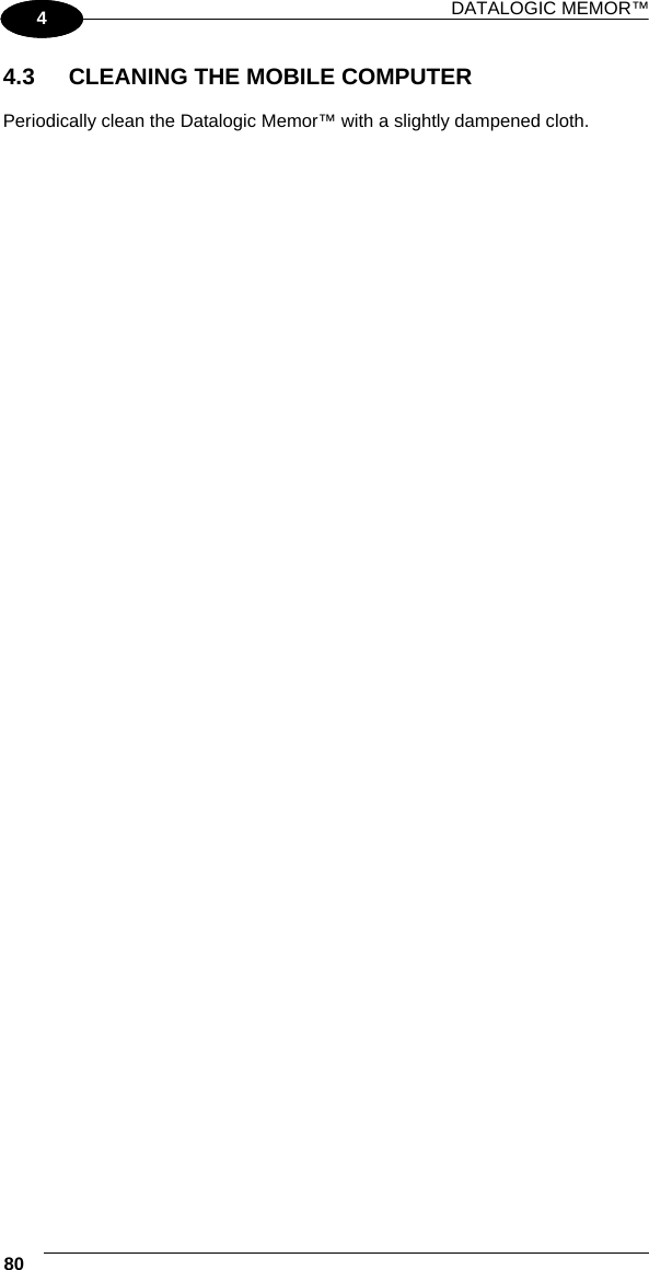
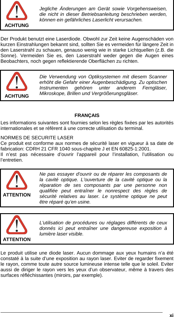
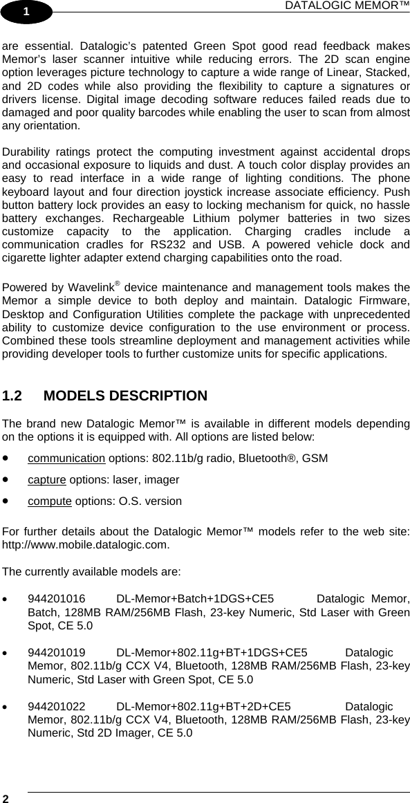
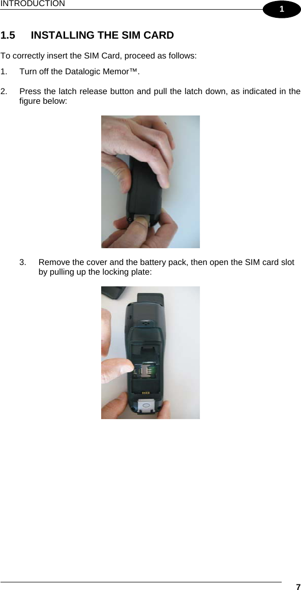
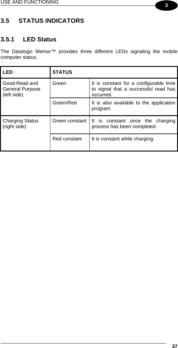
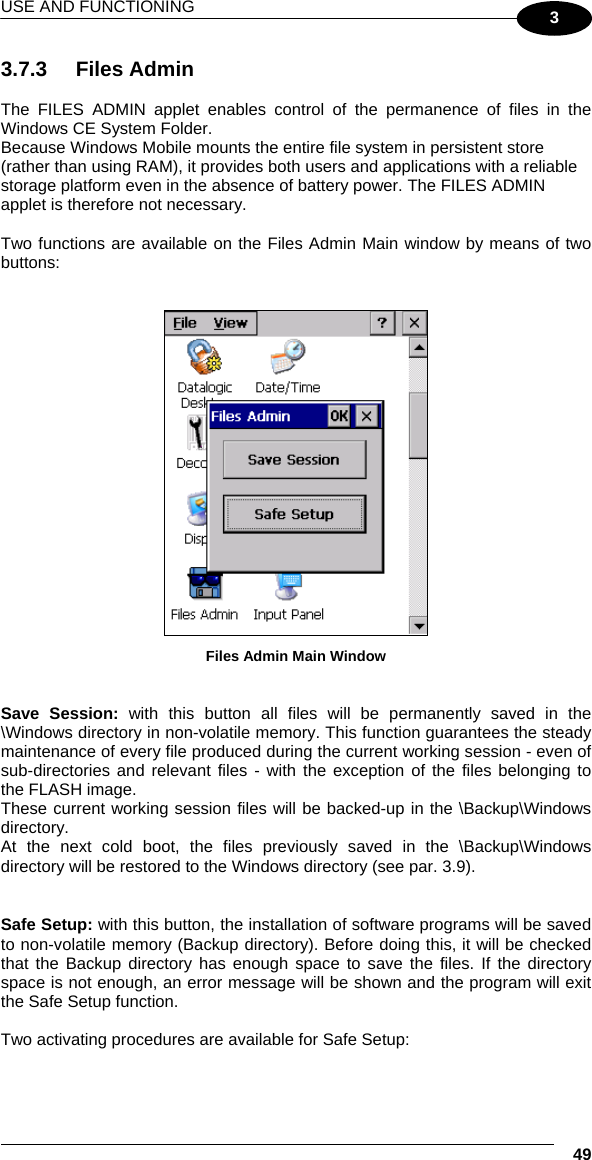
![USE AND FUNCTIONING 73 3 3.9 BACKUP DIRECTORY FILE MANAGEMENT All of the Windows CE 5.0 system files reside in RAM (volatile memory) except for the Backup directory, which resides in FLASH (non-volatile memory). Therefore the contents of the Backup directory are persistent even if the mobile computer is re-booted or the battery pack is changed. You can save your more important files that you don't want to lose due to mobile computer re-boot, in the Backup directory or create a sub-directory within Backup. Even though the Windows Directory resides in RAM, it often contains files or sub-directories created by the user or by installation programs that you don't want to lose at re-boot. To keep these files persistent it is necessary to copy them to the directory \Backup\Windows. This directory doesn't exist originally (only Backup exists), and therefore it must be created. At the next cold boot, before activating the shell, Windows CE 5.0 will copy the contents including all sub-directories of \Backup\Windows to \Windows. Likewise, to maintain files that must be run at Windows CE 5.0 startup, (i.e. .exe, .lnk, .vb, .htm, etc.), it is necessary to copy them to the directory \Backup\Startup. This directory does not exist originally (only Backup exists), and therefore it must be created. The application programs will be run after any type of re-boot (both software and cold boot). As an alternative to the Safe Setup function, it is possible to copy the .cab files to the directory \Backup\Cabfiles (the Cabfiles sub-directory doesn't exists originally and must therefore be created) and perform a mobile computer cold boot to have the application installed. Once these files are copied to the directory \Backup\Cabfiles, the application will be run after each re-boot. From the second cold boot on, a message may be displayed such as "<application name> is already installed. Re-install?". This message blocks the boot process. Press the [Enter] key to continue the system initialization. Even if the entire Windows Mobile file system reside in FLASH (non-volatile memory), the mechanism described above is supported also on Windows Mobile for backward compatibility. 3.10 FIRMWARE UPDATE The Datalogic Memor™ is equipped with a tool that implements a firmware update service. For further information, refer to DFU Reference Guide.](https://usermanual.wiki/Datalogic-S-r-l/0030/User-Guide-1129715-Page-93.png)