Datalogic S r l 004U GSM/GPRS/EDGE/UMTS/HSDPA Module User Manual DL Elf
Datalogic ADC S.r.l. GSM/GPRS/EDGE/UMTS/HSDPA Module DL Elf
UserManual.wiki
>
Datalogic S r l
>
004U User Manual
User Manual
Navigation menu
Upload a User Manual
Namespaces
Wiki Guide
HTML
PDF
Info
Views
User Manual
Discussion / Help
Navigation


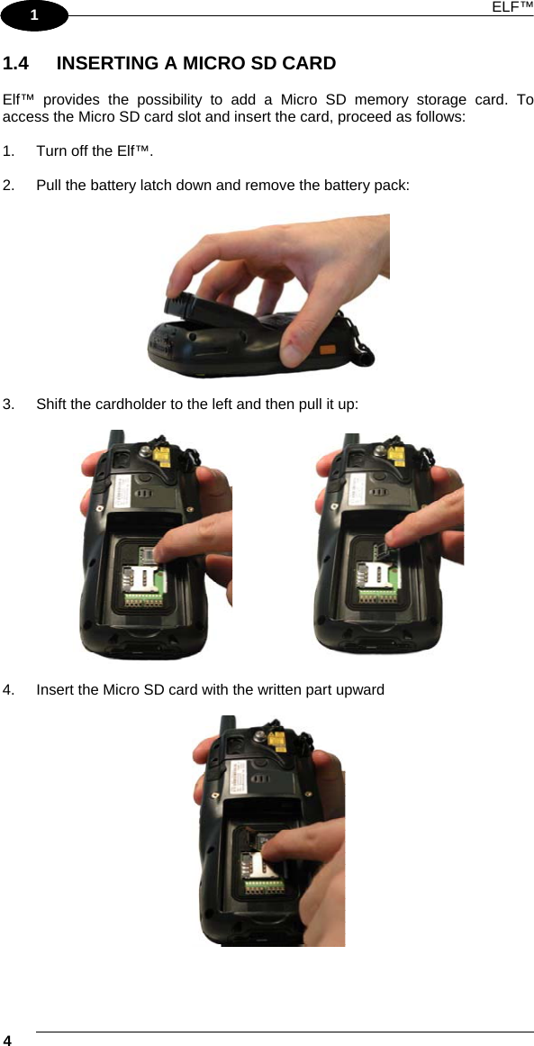
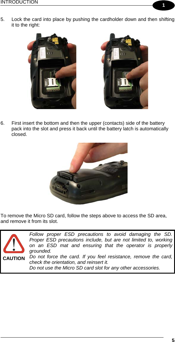
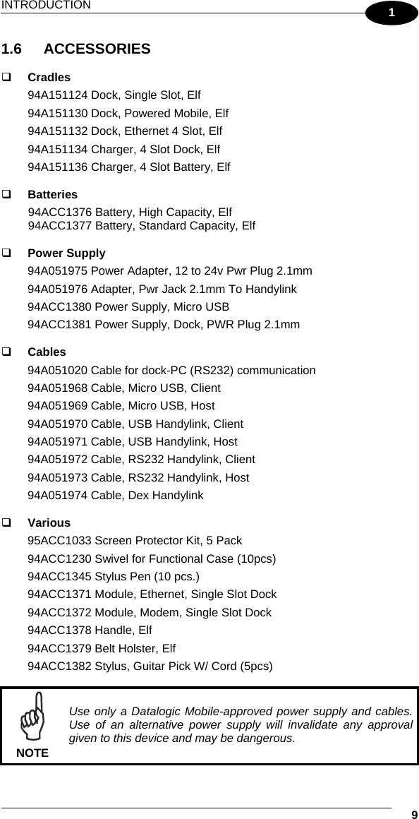
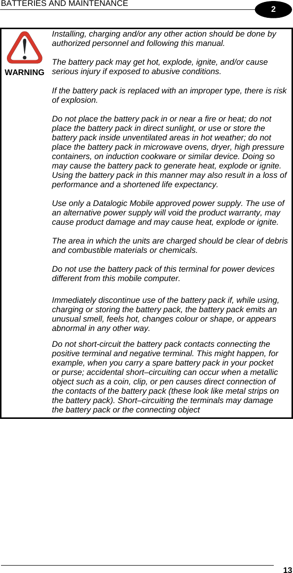
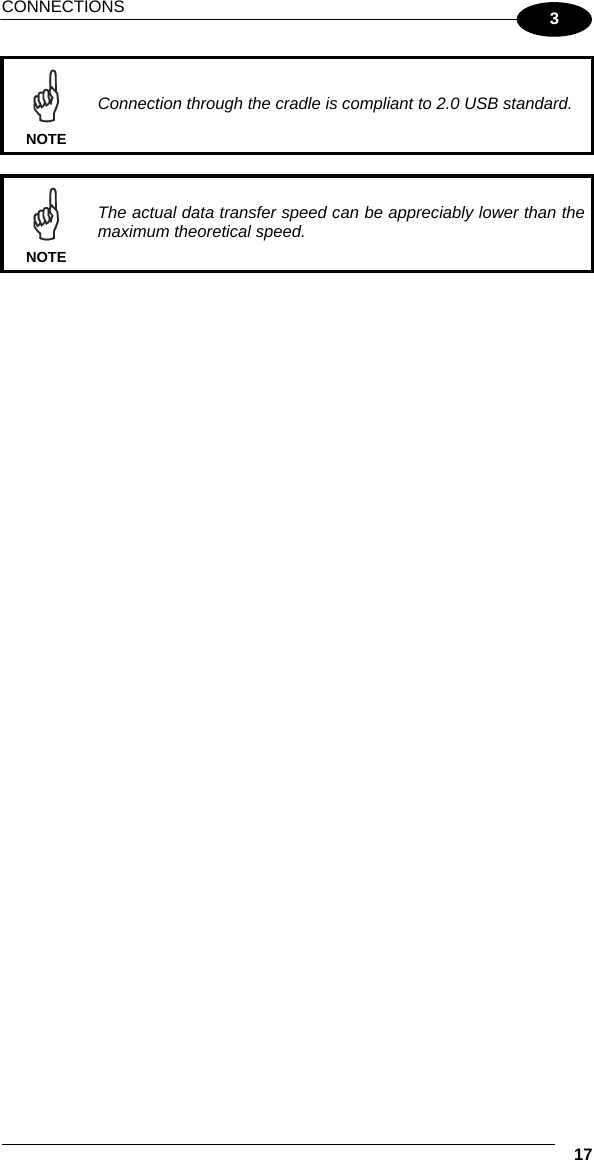
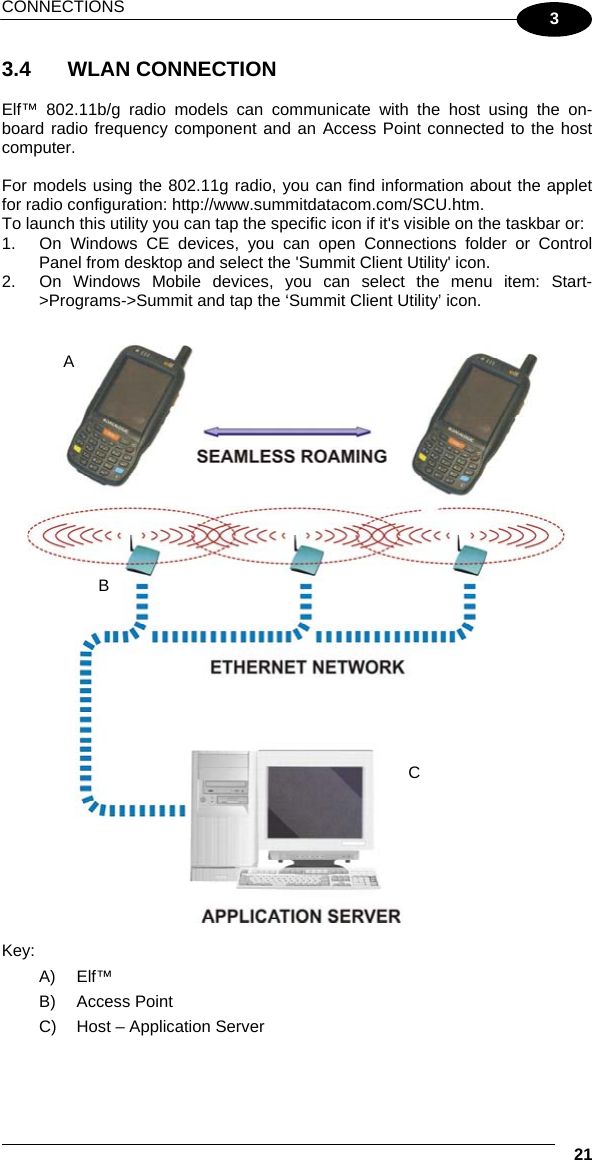
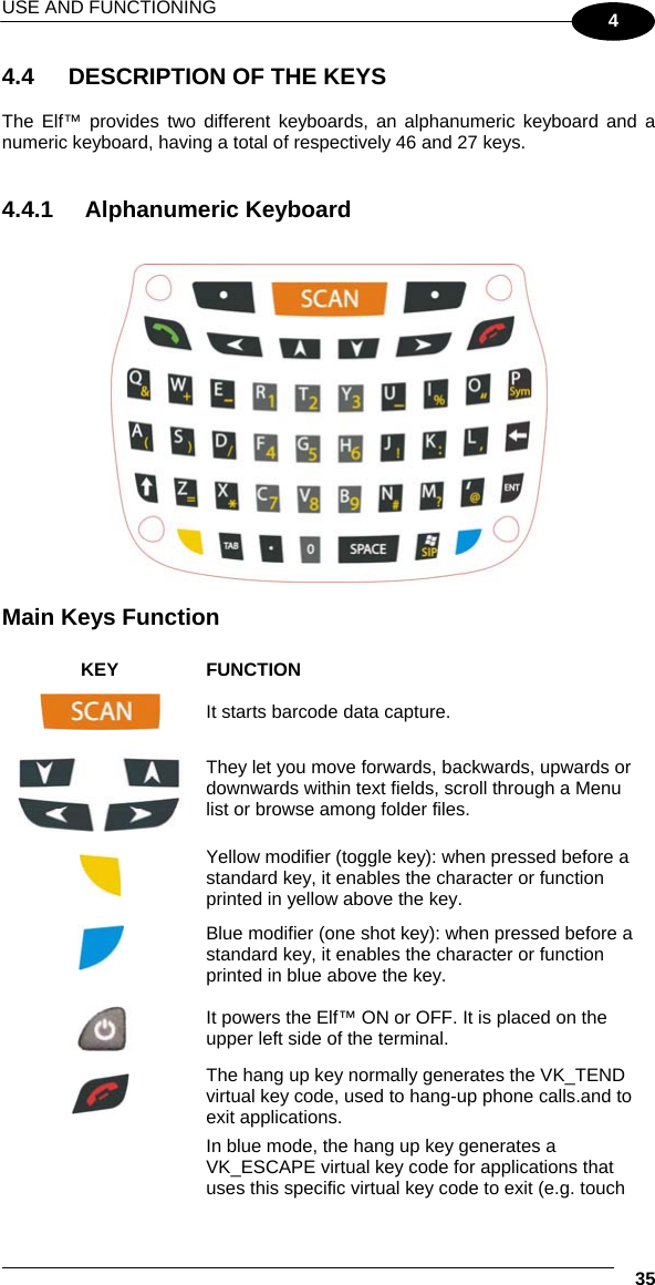
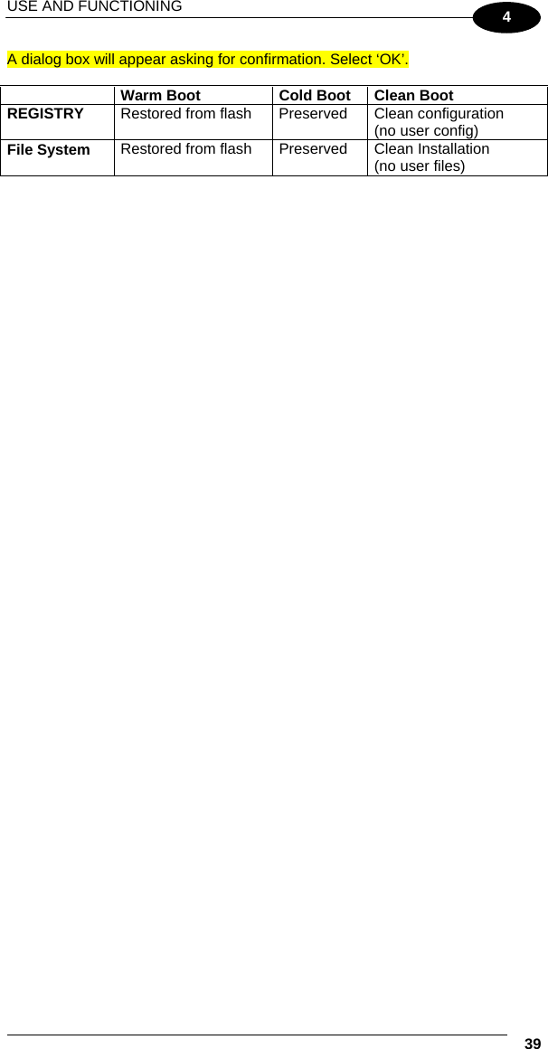
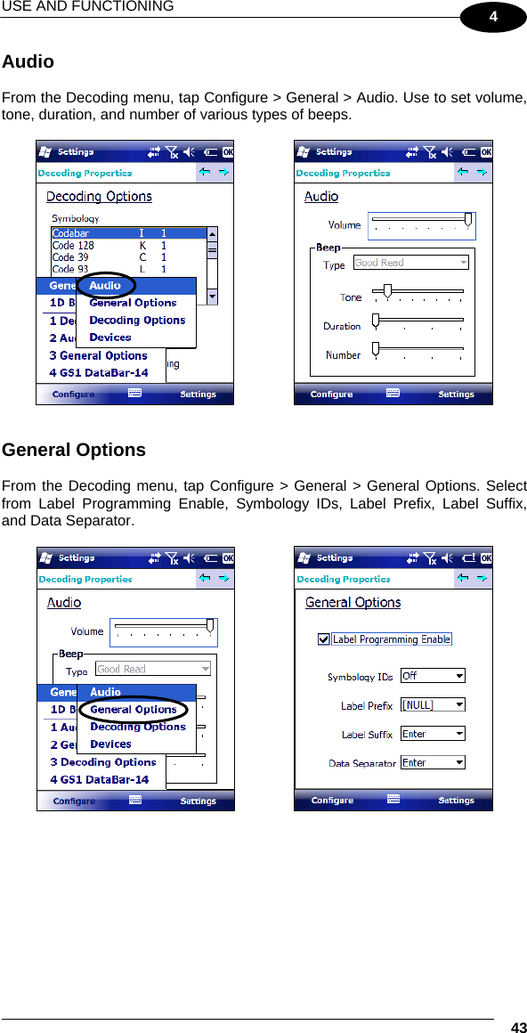
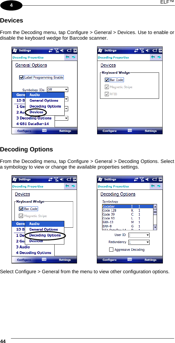
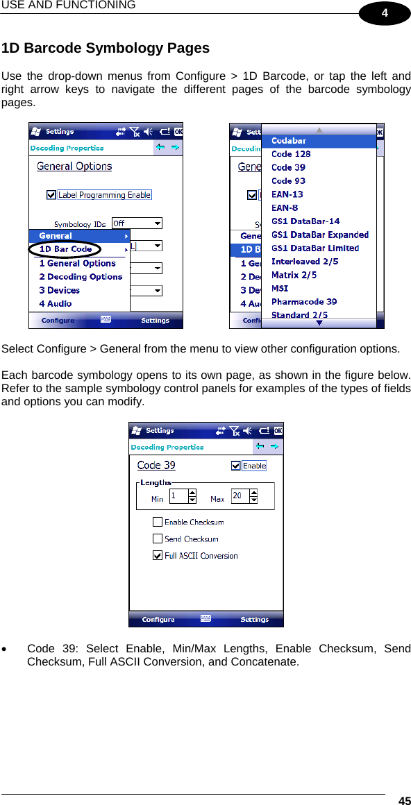
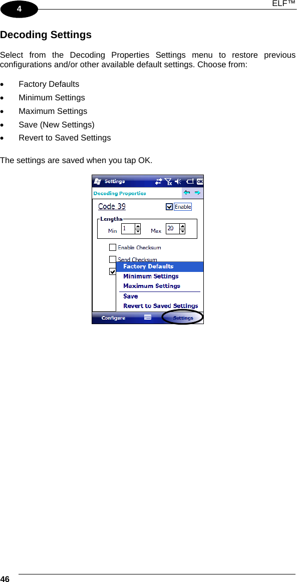
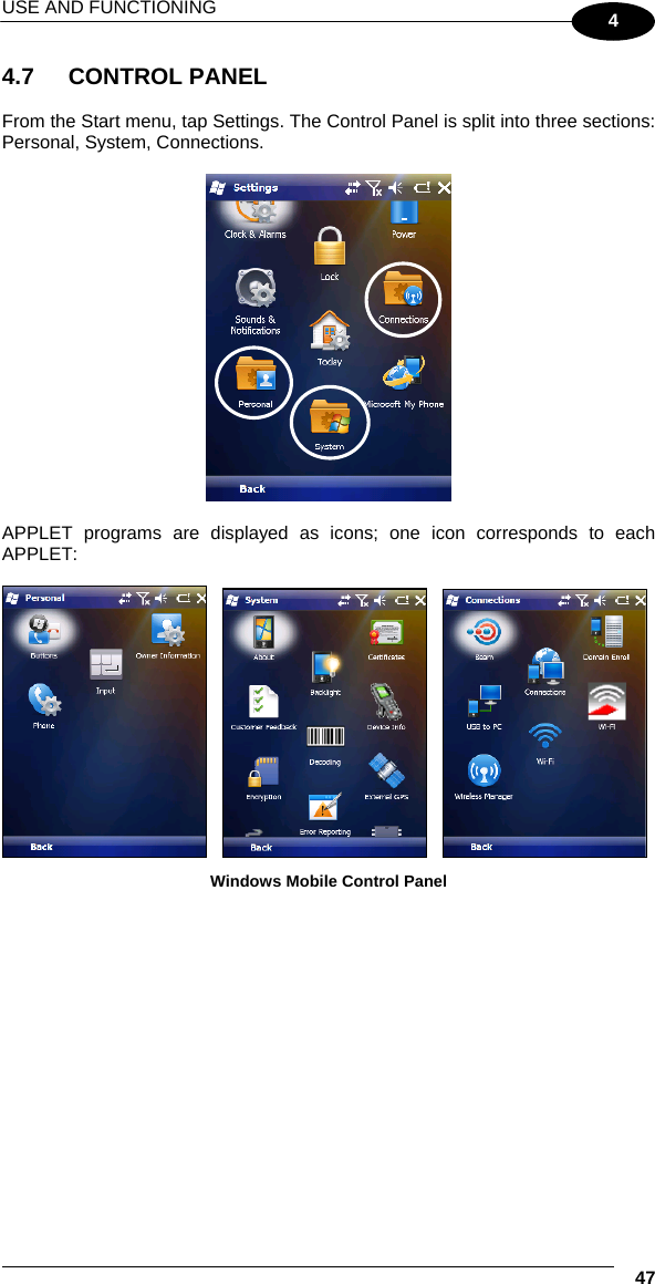
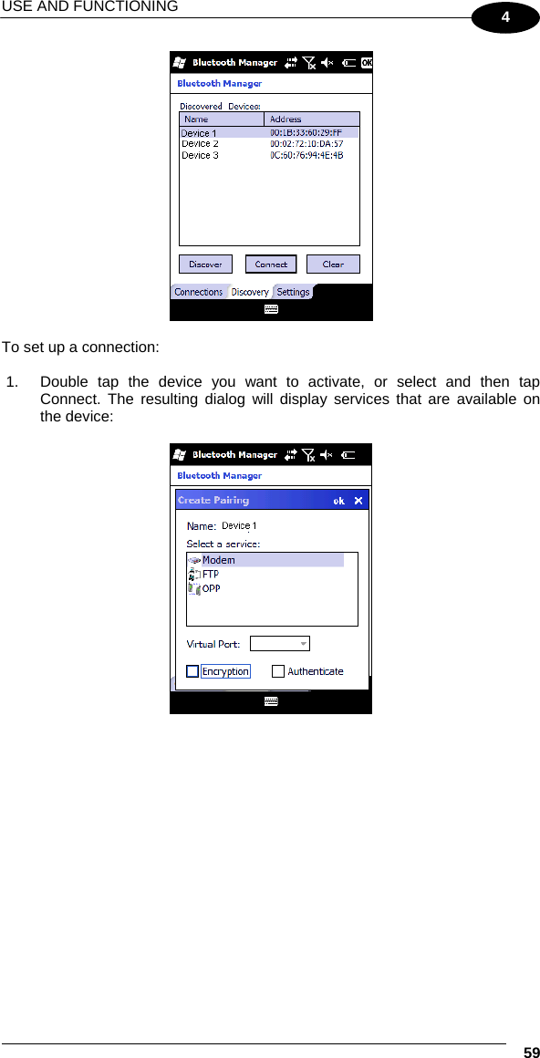
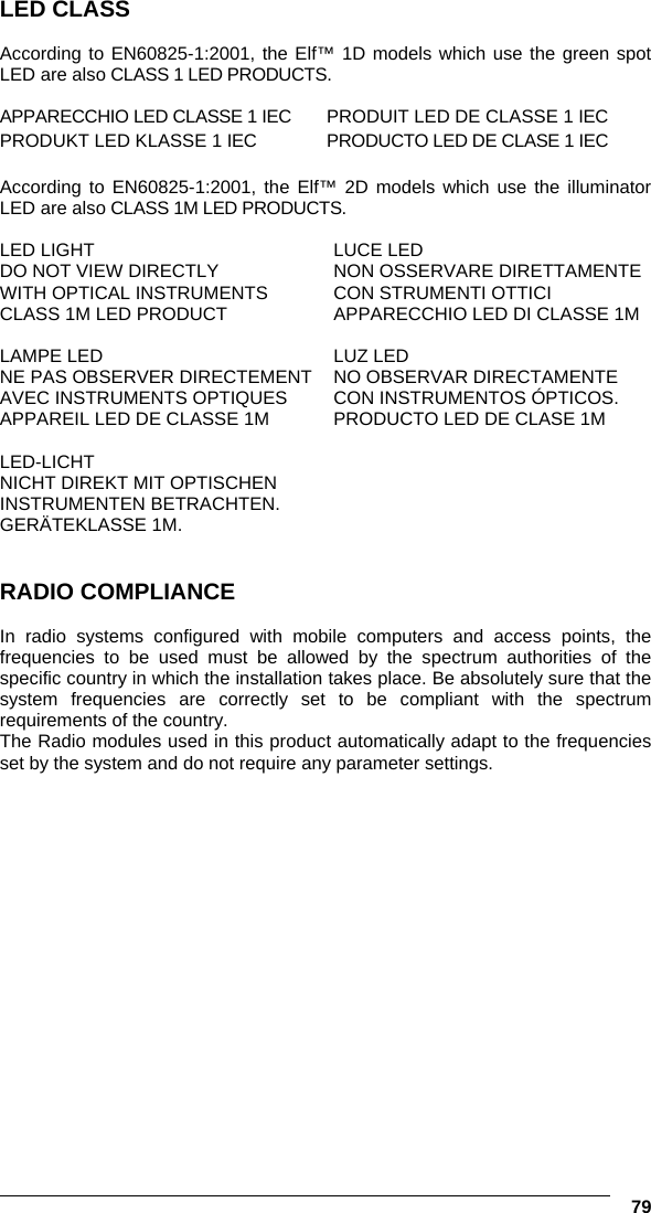
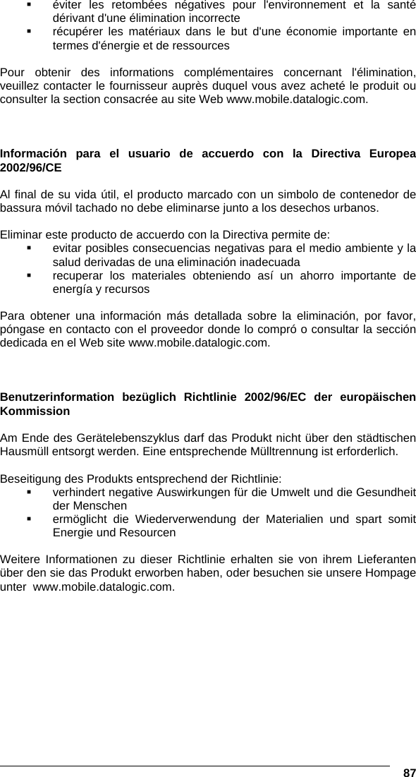
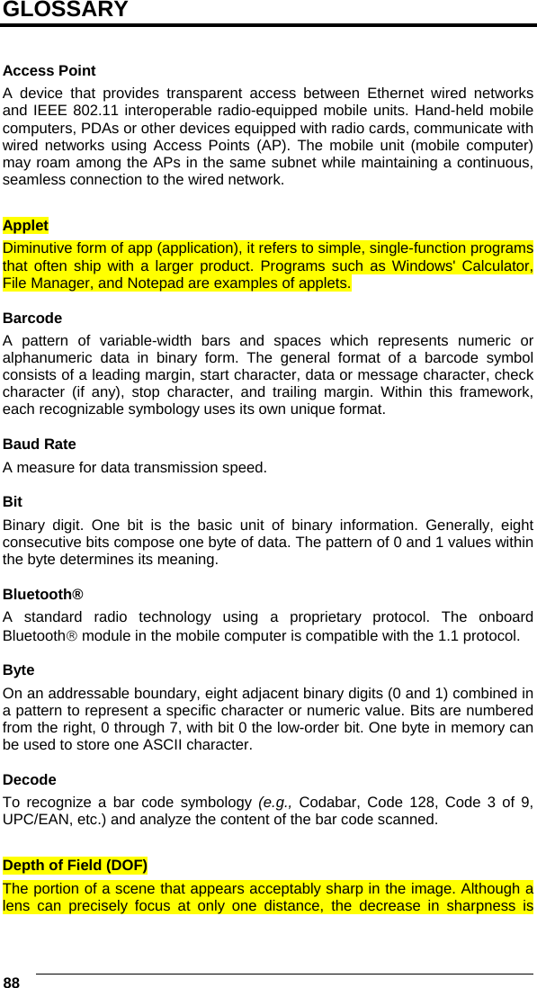
![USE AND FUNCTIONING 29 4 4 USE AND FUNCTIONING The use of the Elf™ depends on the application software loaded. However there are several parameters that can be set and utilities that can be used to perform some basic functions such as data capture, communications, file management, etc. 4.1 STARTUP The Elf™ turns on when the battery pack or the external supply is inserted. After the battery pack is installed, use the [ON/OFF] key to turn the mobile computer on and off. As soon as the mobile computer is on, the Windows Mobile 6.5 desktop configuration will appear on the screen. Wait a few seconds before starting any activity so that the mobile computer completes its startup procedure. Today Screen Start Menu Use the stylus (par. 4.1.1) as suggested to select icons and options. The mobile computer goes into power-off (low power with display and keyboard backlight off), when it is no longer used for more than a programmable timeout, which is defined in the POWER applet of the Control Panel. In this mode it can be awakened (resuming operation) by the [ON/OFF] key. NOTE The mobile computer can also be awakened or turned off by the application program.](https://usermanual.wiki/Datalogic-S-r-l/004U/User-Guide-1394766-Page-36.png)