Datalogic S r l 0060 Skorpio X3 User Manual 61590
Datalogic ADC S.r.l. Skorpio X3 61590
Contents
- 1. user manual
- 2. Integration Guide
Integration Guide
DE2011-DL
Integration Guide
Bar Code Scan Engine
Datalogic ADC, Inc.
959 Terry Street | Eugene | OR 97402 | USA
Telephone: (1) 541-683-5700 | Fax: (1) 541-345-7140
©2014 Datalogic, Inc.
An Unpublished Work - All rights reserved. No part of the contents of this documentation or
the procedures described therein may be reproduced or transmitted in any form or by any
means without prior written permission of Datalogic ADC, Inc. or its subsidiaries or affiliates
("Datalogic" or "Datalogic ADC"). Owners of Datalogic products are hereby granted a non-exclu-
sive, revocable license to reproduce and transmit this documentation for the purchaser's own
internal business purposes. Purchaser shall not remove or alter any proprietary notices,
including copyright notices, contained in this documentation and shall ensure that all notices
appear on any reproductions of the documentation.
Should future revisions of this manual be published, you can acquire printed versions by con-
tacting your Datalogic representative. Electronic versions may either be downloadable from
the Datalogic website (www.datalogic.com) or provided on appropriate media. If you visit our
website and would like to make comments or suggestions about this or other Datalogic publi-
cations, please let us know via the "Contact Datalogic" page.
Disclaimer
Datalogic has taken reasonable measures to provide information in this manual that is com-
plete and accurate, however, Datalogic reserves the right to change any specification at any
time without prior notice.
Datalogic and the Datalogic logo are registered trademarks of Datalogic S.p.A. in many coun-
tries, including the U.S.A. and the E.U. All other brand and product names may be trademarks
of their respective owners.
Patents
This product is covered by one or more of the following patents:
Utility Patents: EP0996284B1; EP0999514B1; EP1128315B1; EP1172756B1; EP1396811B1;
EP1413971B1; EP1804089B1; EP1828957B1; JP4435343B2; JP5192390B2; US6478224;
US6512218; US6808114; US6877664; US6997385; US7053954; US7234641; US7387246;
US8113430; ZL200680050007.8.

Integration Guide
i
Table of Contents
INTRODUCTION........................................................................................................................................................................................... 1
About this Manual ................................................................................................................................................................................................... 1
Manual Conventions ..............................................................................................................................................................................1
Outline .............................................................................................................................................................................................................. 1
Technical Support ..................................................................................................................................................................................................... 2
Datalogic Website Support ............................................................................................................................................................................. 2
Reseller Technical Support ............................................................................................................................................................................. 2
Telephone Technical Support ......................................................................................................................................................................... 2
About the DE2011-DL ............................................................................................................................................................................................. 2
Unpacking the Scan Engine ............................................................................................................................................................................ 2
Scan Engine Care ............................................................................................................................................................................................. 2
External Optics .......................................................................................................................................................................................2
System Overview ............................................................................................................................................................................................. 3
Illumination System ........................................................................................................................................................................................ 3
Regulatory ..............................................................................................................................................................................................3
Aiming System ................................................................................................................................................................................................ 3
Aiming Pattern .......................................................................................................................................................................................4
Aiming System Parameters .................................................................................................................................................................4
Regulatory ...............................................................................................................................................................................................4
INSTALLATION............................................................................................................................................................................................ 7
Mounting the Scan Engine ...................................................................................................................................................................................... 7
General Considerations .................................................................................................................................................................................. 7
Mechanical Size ............................................................................................................................................................................................... 7
Mounting Holes ............................................................................................................................................................................................... 8
Housing Design ............................................................................................................................................................................................... 8
Positioning the exit window .................................................................................................................................................................8
Avoiding scratched windows ................................................................................................................................................................9
Window material ....................................................................................................................................................................................9
Exit window properties ........................................................................................................................................................................10
Optical paths and exit window clearance ..........................................................................................................................................11
Environment .........................................................................................................................................................................................12
ELECTRICAL INTEGRATION...................................................................................................................................................................... 13
Electrical Connections ........................................................................................................................................................................................... 13
Grounding ....................................................................................................................................................................................................... 13
ESD .........................................................................................................................................................................................................13
Electrical Interface ................................................................................................................................................................................................ 13
Connector and Flat cable .....................................................................................................................................................................14
Powerup sequence ...............................................................................................................................................................................14
Engine latency at powerup .................................................................................................................................................................14
Supply Voltages and I/O levels .................................................................................................................................................................... 15
Power supply noise ..............................................................................................................................................................................15
SOFTWARE INTERFACE........................................................................................................................................................................... 17
Communication Protocol ....................................................................................................................................................................................... 17
Command Format ......................................................................................................................................................................................... 17
Engine Response Format ....................................................................................................................................................................18
I2C Command Codes ..................................................................................................................................................................................... 19
Command Parameters ........................................................................................................................................................................19
Camera System Parameters ........................................................................................................................................................................23
TECHNICAL SPECIFICATIONS .................................................................................................................................................................. 25
Definition of Scanning Angles ...................................................................................................................................................................... 27
Power Consumption Details ........................................................................................................................................................................28
I2C COMMAND SPECIFICATIONS ............................................................................................................................................................ 29
I2C Command Specifications ................................................................................................................................................................................30
AIM TIME (0x4E) ....................................................................................................................................................................................30
AIM TOGGLE (0x35) ...............................................................................................................................................................................30

Contents
ii
DE2011-DL
AUTO LOW POWER (0x44) ...................................................................................................................................................................30
BOOTLOADER START (0x41) ................................................................................................................................................................30
CAMERA MODE (0x3B) .........................................................................................................................................................................30
CAMERA RESET (0x37) .........................................................................................................................................................................31
CAMERA START (0x38) .........................................................................................................................................................................31
GET CAMERA PARAM (0x40) ...............................................................................................................................................................31
GET SENSOR REGISTER (0x31) ..........................................................................................................................................................31
ILLUMINATION DELAY (0x34) ..............................................................................................................................................................32
ILLUMINATION ENABLE (0x39) ...........................................................................................................................................................32
ILLUMINATION TIME (0x48) .................................................................................................................................................................32
RESTORE FACTORY DEFAULT (0x23) ..................................................................................................................................................32
RUN CMD LIST (0x47) ...........................................................................................................................................................................32
SET AUTO POWER TIME (0x45) ...........................................................................................................................................................32
SENSOR BINNING (0x3C) ......................................................................................................................................................................32
SET CAMERA PARAM (0x41) ................................................................................................................................................................33
SET COMMAND LIST (0x46) .................................................................................................................................................................33
SET LOW POWER (0x3F) ......................................................................................................................................................................34
SET SENSOR REG (0x30) ......................................................................................................................................................................34
ENGINE VIDEO FORMAT.......................................................................................................................................................................... 35
Sensor Data Format ...................................................................................................................................................................................... 35
Output Data Timing ....................................................................................................................................................................................... 36
Sensor Registers Settings ............................................................................................................................................................................ 36
ACCESSORIES ........................................................................................................................................................................................... 37
Green Spot Projector ..............................................................................................................................................................................................37
Green Spot Projector - Left side mounting ................................................................................................................................................ 37
Green Spot Projector - Right side mounting .............................................................................................................................................. 39
Integration Guide
1
Chapter 1
Introduction
About this Manual
This Integration Guide is provided to give instruction, opto-mechanical
details, and design considerations to integrate the DE2011-DL model (des-
ignated as “scan engine” or “OEM scan engine” in this manual) specifically
into equipment-integrated scanning applications.
Manual Conventions
The following conventions are used in this document:
The symbols listed below are used in this manual to notify the reader of key
issues or procedures that must be observed when using the reader:
Notes contain information necessary for properly diagnosing,
repairing and operating the reader.
CAUTION
The CAUTION symbol advises you of actions that could damage
equipment or property.
Outline
Chapter 1, Introduction (this chapter) presents information about manual
conventions and an overview of the engine, its features and operation.
Chapter 2, Installation provides information about unpacking, cable connec-
tion information and setting up the scan engine for optimum scan engine
performance.
Chapter 3, Electrical Integration offers information about electrical compo-
nents.
Chapter 4, Software Interface describes software commands.
Appendix A, Technical Specifications lists physical and performance charac-
teristics, as well as environmental and regulatory specifications.
Appendix B, I2C Command Specifications offers additional information about
I2C Commands.

Introduction
2
DE2011-DL
Technical Support
Datalogic Website Support
The Datalogic website (www.datalogic.com) is the complete source for tech-
nical support and information for Datalogic products. The site offers product
support, warranty information, product manuals, product tech notes, soft-
ware updates, demos, and instructions for returning products for repair.
Reseller Technical Support
An excellent source for technical assistance and information is an autho-
rized Datalogic reseller. A reseller is acquainted with specific types of busi-
nesses, application software, and computer systems and can provide
individualized assistance.
Telephone Technical Support
If you do not have internet or email access, you may contact Datalogic tech-
nical support at (541) 349-8283 or check the back cover of your manual for
more contact information.
About the DE2011-DL
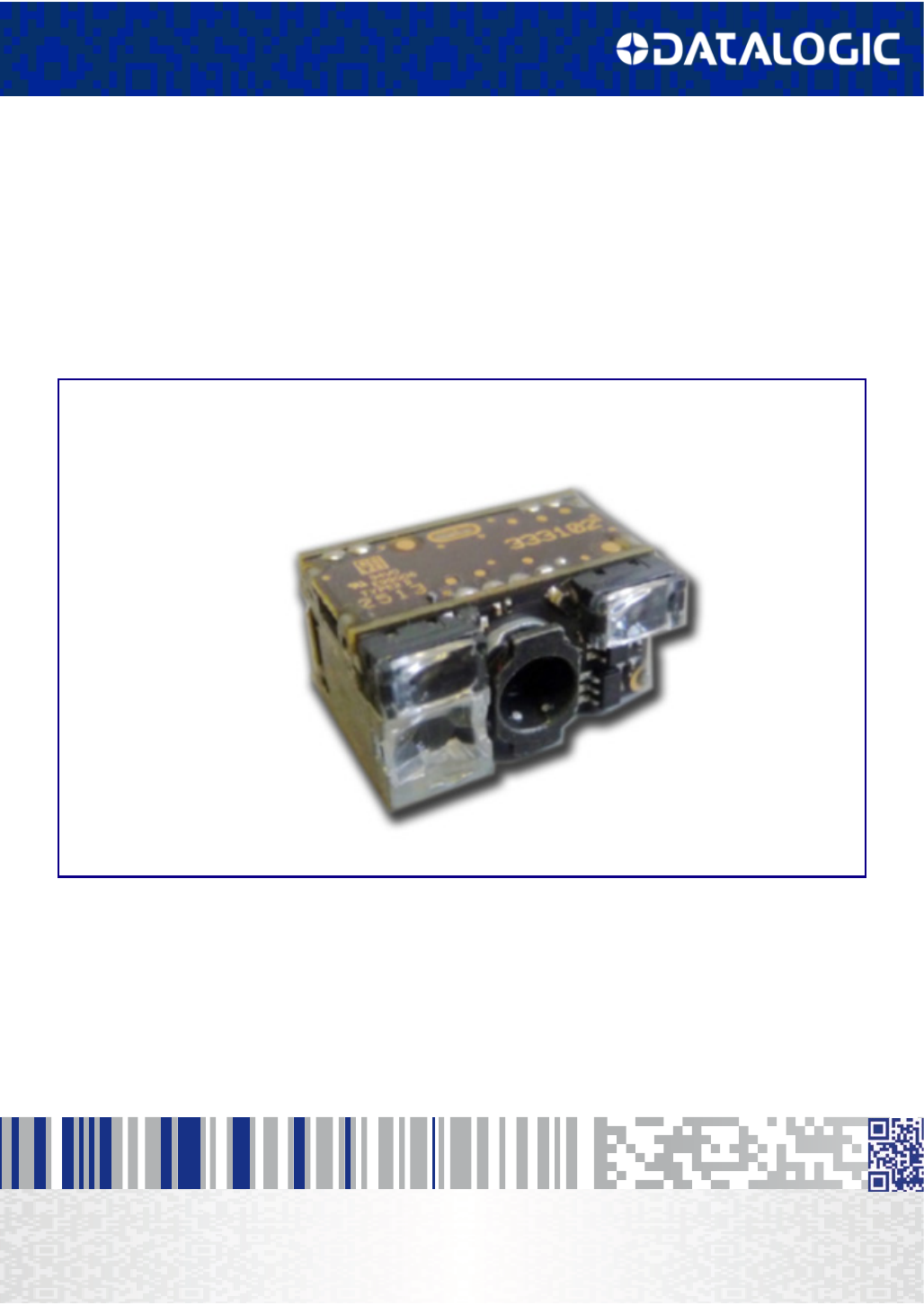
The Datalogic DE2011-DL is a very compact, high performance undecoded
imager used to capture digital images to be transferred to an external digital
platform, to provide the ability to decode any kind of bar code symbols.
Unpacking the Scan Engine
The scan engine is shipped in custom packaging. Carefully open the pack-
age, and inspect for the following:
•scan engine
• interface cable (if ordered)
If any parts are damaged or you need additional hardware, please contact
Technical Support.
Scan Engine Care
The scan engine contains sensitive components which require special han-
dling. Datalogic may not warrant damage due to improper handling.
• Do not disassemble the scan engine. Doing so will void the warranty.
• Use standard ESD precautions & policies when handling the DE2011-DL
scan engine.
External Optics
The engine has an exposed illumination system and aiming lenses on the
outer surfaces. Take care of these optical components, preserving the lenses
from mechanical stresses that can damage them. Avoid touching the optical
surfaces to preserve the optical performance.
About the DE2011-DL
Integration Guide
3
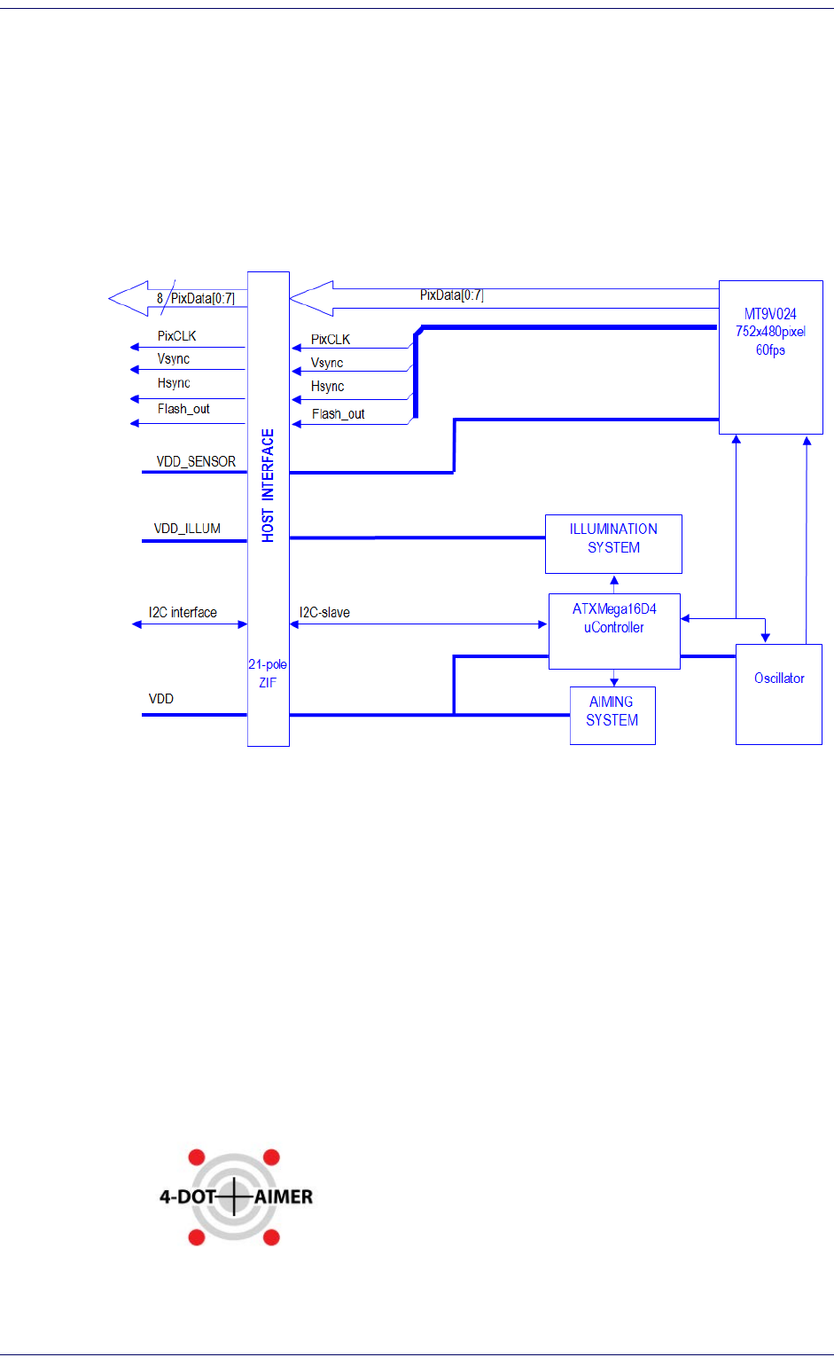
System Overview
The Datalogic DE2011 scan engine features a global shutter sensor having
752x480 pixels, able to capture images at 60 frames per second.
The engine contains an embedded illumination system and an aiming sys-
tem. A high performance, low power micro-controller runs the engine sys-
tem and handles communication with the external host. The host interface is
available as a 21-pole zif connector.
Figure 1. Engine block diagram
Illumination System
The Illumination System is comprised of two white LEDs and non-imaging
optics designed to provide first-class reading performances, even in total
darkness.
Regulatory
• EN/IEC 62471 (exempt)
Aiming System
The aiming system is based on a 650nm laser diode and related optics. It
projects a highly visible 4-Dot aimer with center-cross for targeted scan-
ning.
Introduction
4
DE2011-DL
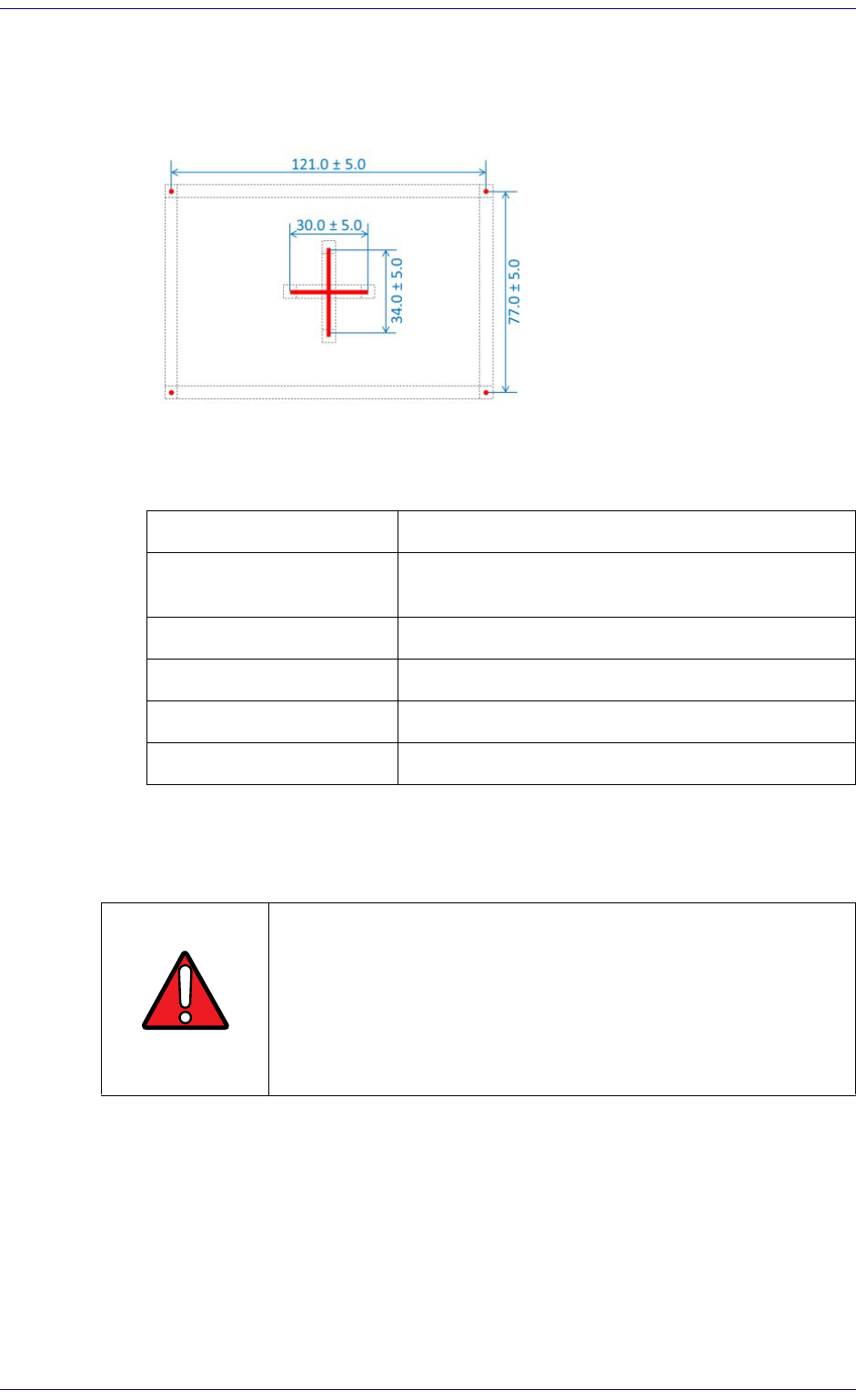
Aiming Pattern
The central cross represents the center of the field of view, while the four
dots show the boundaries of the field of view.
Figure 2. Projected pattern at 200 mm
Aiming System Parameters
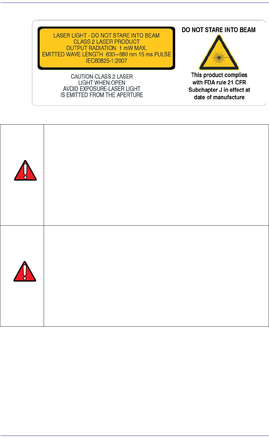
Regulatory
• EN/IEC 60825-1:2007 (class 2)
• 21 CFR 1040 (CDRH) (class II)
WARNING
Viewing the laser output with certain optical instruments (for
example, eye loupes, magnifiers, and microscopes) within a dis-
tance of 100mm may pose an eye hazard.
Wavelength 630-680 nm
Beam Divergence 35° (horizontal) x 25° (vertical) – see
Figure 8 on
page 11
and
Figure 9 on page 11
Maximum pulse duration 15ms
Repetition rate 16.6ms
Maximum output power 1mW
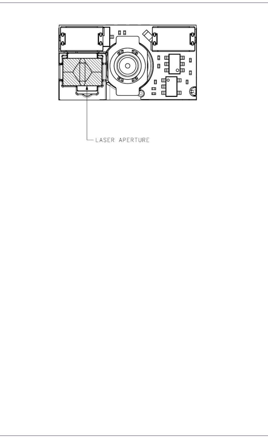
Laser aperture See
Figure 10 on page 12
About the DE2011-DL
Integration Guide
5
Figure 3
. DE2011-DL Regulatory label
WARNING
STANDARD LASER SAFETY REGULATIONS
This product conforms to the applicable requirements of both CDRH 21 CFR 1040
and EN 60825-1 at the date of manufacture. For installation, use and maintenance,
it is not necessary to open the device.
Use of controls or adjustments or performance of procedures other than those
specified herein may result in exposure to hazardous visible laser light.
The product utilizes a low-power laser diode. Although staring directly at the laser
beam momentarily causes no known biological damage, avoid staring at the beam
as one would with any very strong light source, such as the sun. Avoid that the laser
beam hits the eye of an observer, even through reflective surfaces such as mirrors,
etc.
ATTENTION
NORMES DE SECURITE LASER
Ce produit est conforme aux normes de sécurité laser en vigueur à sa date de fabri-
cation: CDRH 21 CFR 1040 et EN60825-1. Il n’est pas nécessaire d’ouvrir l’appareil
pour l’installation, l’utilisation ou l’entretien.
L'utilisation de procédures ou réglages différents de ceux donnés ici peut entraîner
une dangereuse exposition à lumière laser visible.
Le produit utilise une diode laser. Aucun dommage aux yeux humains n’a été con-
staté à la suite d’une exposition au rayon laser. Eviter de regarder fixement le rayon,
comme toute autre source lumineuse intense telle que le soleil. Eviter aussi de
diriger le rayon vers les yeux d’un observateur, même à travers des surfaces
réfléchissantes (miroirs, par exemple).

Introduction
6
DE2011-DL
NOTES
Integration Guide
7
Chapter 2
Installation
This section describes how to design the mounting for optimum scan engine
performance.
Mounting the Scan Engine
General Considerations
A typical system uses the scan engine mounted inside a host enclosure, with
an opening for the illumination system light to exit and illuminate the label,
and to read bar codes. The opening should be the size of the scan engine
field of view at a minimum, but only exposing as much of the scan engine as
necessary.
It is important to consider the effect of the environment on the scan engine.
In particular, mounting should minimize the possibility of foreign objects
coming into contact with the electronics. Such contact could damage the
device or reduce the scan engine’s performance.
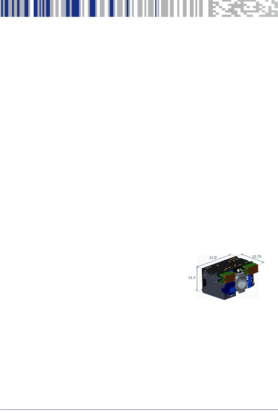
Mechanical Size
Figure 4
Nominal size:
21.0mm (width) x 11.4mm (height) x 15.75mm
(depth)
Maximum size:
21.15mm (width) x 11.55mm (height) x
15.91mm (depth)
. Nominal Engine Size
Installation
8
DE2011-DL
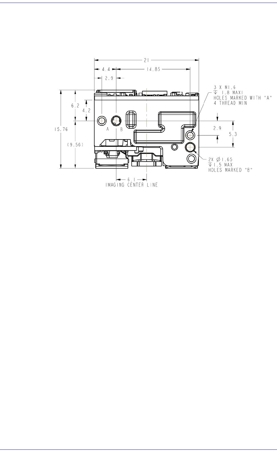
Mounting Holes
There are three mounting holes M1.6x0.35mm located on the bottom of the
chassis. The recommended thread engagement for the screws is 1.7mm
(holes marked with “A”), with a mounting torque of 0.15Nm.
Figure 5. Mounting holes and related requirements
Housing Design
The enclosure must be designed to prevent internal reflections from illumi-
nation and aiming systems into the receiving optics.The exit window must
be properly positioned and tilted to avoid reflections that could limit engine
performance, both for decoding and image capture.
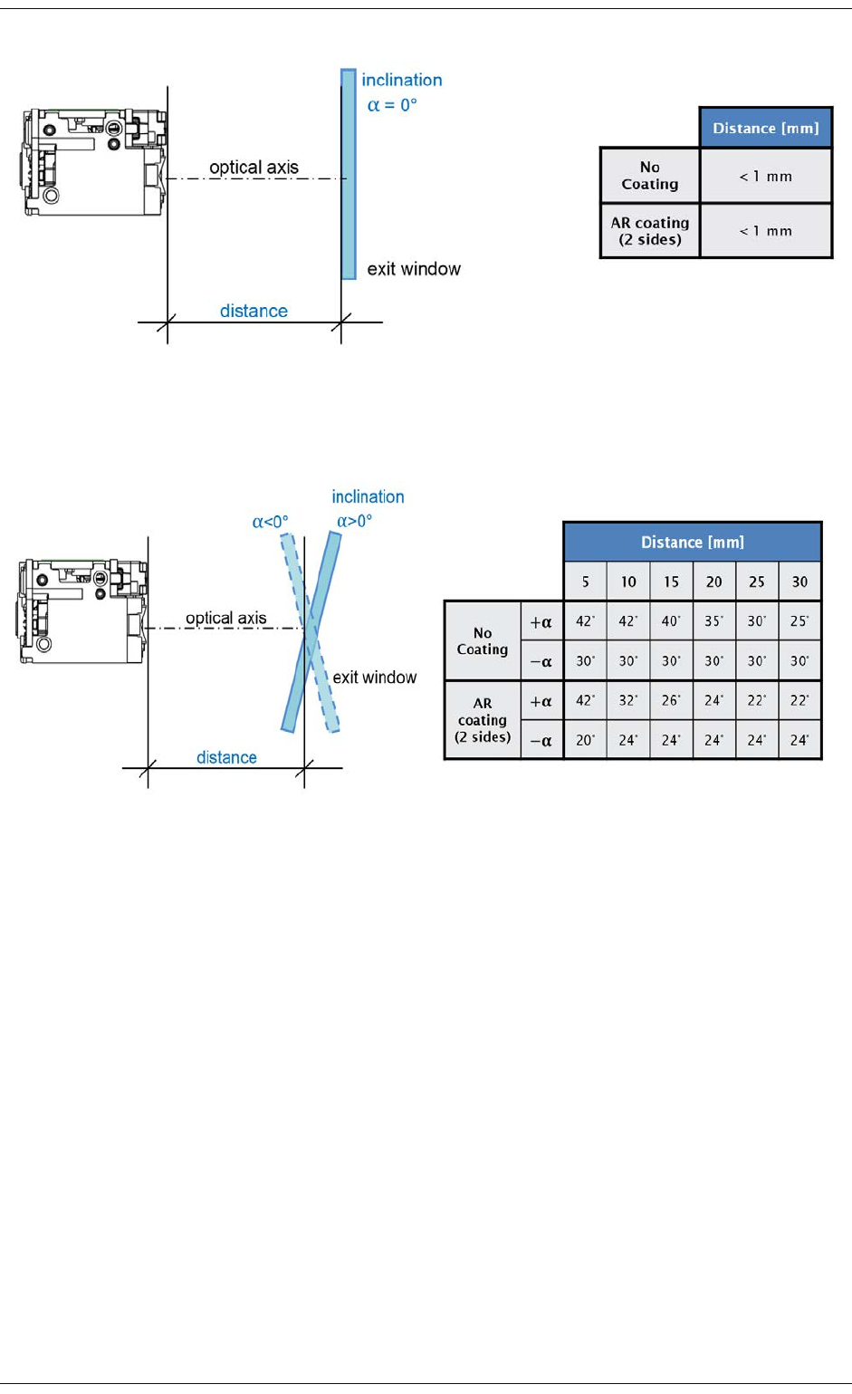
Positioning the exit window
There are two options for positioning the exit window with respect to the
engine optical axis:
• Perpendicular
•Tilted
Distances are measured from the illumination lenses to the first face of the
exit window (the nearest to the engine). Window thickness should be smaller
or equal to 1.5mm.
The use of a double-sided AR coated exit window is strongly recommended
both for perpendicular and tilted windows.
Mounting the Scan Engine
Integration Guide
9
Figure 6. Exit window positioning – perpendicular window
Figure 7. Exit window positioning – tilted window
Avoiding scratched windows
Scratches on the exit window can strongly affect the reading performance. It
is recommended to use an exit window having a scratch-resistant coating
and to position the engine window in a recessed position.
Window material
The exit window is an integral part of the imaging system and should be
designed and selected to preserve the optical quality of the system. It is rec-
ommended to use only cell-cast plastics or optical glass.
Common materials and their characteristics are shown in Table 1on the fol-
lowing page.

Installation
10
DE2011-DL
Table 1. Exit window materials
Optical Quality Very good Very good
Surface Hardness Hard coating required Hard coating required
Impact Resistance Good Good
Chemical / UV Resistance Susceptible Susceptible
Ultrasonically Welding Compatible Compatible
Exit window properties
Recommended properties/performance of the exit window are reported in
Table 2 below.
Table 2. Exit Window Properties
Material PMMA or CR39 or equivalent
Thickness 1.5mm
Wavefront distortion
0.2 wavelengths peak-to-valley maximum and
0,04
λ
maximum rms over any 2.0mm diameter within the clear
aperture
Clear aperture To extend to within 1.0mm of edges all around
Surface quality 60/20 scratch/dig
AR coating
• double sided
• transmittance > 97% minimum within spectrum range
400nm-750nm.
• reflections max 0,4% per side in the range 620nm-640nm
Properties
PMMA
(cell cast acrylic or
polymethyl methacrylic)
CR39
(Allyl Diglycol
Carbonate)
Characteristics Requirement
Mounting the Scan Engine
Integration Guide
11
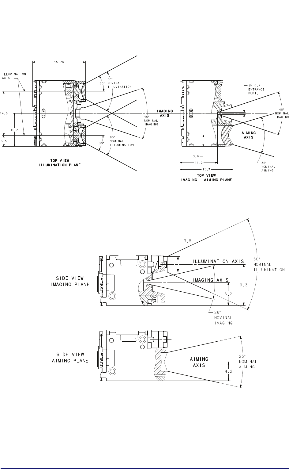
Optical paths and exit window clearance
Figure 8 and Figure 9 show the optical paths for the imaging system, the
aiming system and the illumination system.
Figure 8. Top view - Aiming, imaging and illumination optical paths
Figure 9. Side View - Aiming, imaging and illumination optical paths
Installation
12
DE2011-DL
Figure 10. Front View - Laser aperture
Environment
Dust on the optical parts of the engine can badly affect the performance of
the scan engine. Ensure the engine is clear of dust and water when integrat-
ing it inside the housing.

Integration Guide
13
Chapter 3
Electrical Integration
Electrical Connections
Grounding
The chassis of the engine is at ground. Mounting screws can be used to
implement additional connections to the host ground.
Based on the host characteristics, the additional ground connections can
affect:
• the engine performance (if noise is injected into the scan engine)
• the radiated emission (depending on current loops)
It is suggested to investigate these topics at the beginning of the integra-
tion.
ESD
The engine is protected from ESD up to ±2.0Kv@ connector.
During installation it is recommended to apply standard ESD handling pro-
cedures, such as operating in a properly grounded working area using wrist
straps.
Electrical Interface
The DE2011-DL scan engine can be connected to an external digital plat-
form via a 21-pole ZIF connector supporting:
• a parallel video port (8 bit per pixel, vertical and horizontal synchs,
pixel clock)
• a signal to synchronize an external illumination system with the expo-
sure of the sensor (Flash_out)
• three dedicated power supplies (for sensor, digital system, illumination
system)
•an I
2C communication port for controlling the scan engine
Table 3 below describes the power lines and the signals mapped on the 21-
pole ZIF connector.

Electrical Integration
14
DE2011-DL
Table 3. Engine connector description
GND power Ground
2GND power Ground
3I2C_CLK II2C Clock
4 I2C_DATA I/O I2C Data
5V_SYNC OVertical sync
6PIX_DATA_7 OVideo data bus, pixel 7 – MSB
7PIX_DATA_6 OVideo data bus, pixel 6
8PIX_DATA_5 OVideo data bus, pixel 5
9PIX_DATA_4 OVideo data bus, pixel 4
10 PIX_DATA_3 OVideo data bus, pixel 3
11 PIX_DATA_2 OVideo data bus, pixel 2
12 PIX_DATA_1 OVideo data bus, pixel 1
13 PIX_DATA_0 OVideo data bus, pixel 0 – LSB
14 FLASH_OUT OExternal illumination system trigger
15 VDD_SENSOR power Sensor power supply
16 VDD power Digital power supply
17 VDD_ILLUM_SYS power Illumination system power supply
18 H_SYNC OHorizontal sync
19 GND power Ground
20 PIX_CLK OSensor pixel clock
21 GND power Ground
Connector and Flat cable
The DE2011-DL scan engine is equipped with a Kyocera 21-pole ZIF con-
nector having a pitch of 0.3mm – series 6283 - ordering code 04 6283 021
002 868.
For further details and requirements related to the flat cable, please refer to
the manufacturer’s datasheet, available athttp://www.kyocera‐connec‐
tor.com/prdct/type/fpc/index.html#2
Powerup sequence
In order to guarantee the correct operation of the engine, it is mandatory to
use the following powerup sequence timing constraints:
• VDD_SENSOR must be stable at 3.3V not later than 6ms after the VDD is
at 2.1V.
• VDD_ILLUM_SYS
must be stable at 3.3V at least 20ms before issuing
any camera start command.
Engine latency at powerup
At powerup the engine begins executing the code when the power supply
level reaches 2.1V. To complete the boot sequence, a 12ms time is required.
After this, the engine is ready to parse commands.
Pin Signal I/O type Description
1

Electrical Interface
Integration Guide
15
Supply Voltages and I/O levels
Table 4. Supply Voltages and I/O Levels
VDD_SENSOR 3.3V ± 0.3
The image sensor power supply, from which the analog
power supply is also generated. The value of 3.0V has to be
considered as an inferior limit, but for having superior
power supply noise immunity, a value above 3.15V is rec-
ommended
VDD 3.3V ± 0.3 The digital and laser aiming system power supply.
VDD_ILLUM_SYS 3.0V to 5.0V The LED illumination system power supply.
I/O level 3.3V The typical high level for input and output signals.
Power supply noise
To preserve image quality (both for decoding and image capture applica-
tions), a low-noise power supply is required, particularly for VDD_SENSOR.
The requirement for the power supply peak-to-peak noise is ≤150mV on all
three power supply lines (the lower the better).
Item Level Description

Electrical Integration
16
DE2011-DL
NOTES
Integration Guide
17
Chapter 4
Software Interface
Communication Protocol
The engine provides a bidirectional control interface for the communication
with the integrating platform based on the I2C communication. This is a
master/slave and host-initiated command/response type of protocol, and
the engine always acts as a slave.
It does not support unsolicited responses, meaning that all transactions that
involve sending a command and receiving a response are always initiated by
the host system.
The time needed for execution depends on the command sent. If the engine
does not respond when requested by the host, it is possible that the com-
mand is still being processed. In this case, the master will be forced into a
wait state until the slave is ready.
The maximum waiting time between receiving a command and the response
request is 1 second. After this time a system timeout occurs and the engine
will reset.
Command Format
Commands sent via I2C from host (master) to engine (slave) should have the
following format:
Start bit Address Command
(hex code)
Command
Parameters
…Checksum Stop bit
I2C Element Description
Start bit:
Start bit as
I2C
standard specification.
Address:
Target slave address includes device address plus
write
option
(0x00).
For the engine, slave address is 0x5C (or 0xB8 after shifting to
7bit MSB).
Command:
See list of possible command codes for DE2011 in
I2C Com-
mand Codes, starting on page 19
or
Table 5 on page 19
.

Software Interface
18
DE2011-DL
Engine Response Format
When the host requests a response from the engine, the response format
will be:
Same as for sent Command Format, plus:
Target slave address includes device address plus
read
option
(0x01).
For the engine, slave address is 0x5C (or 0xB8 after shifting to 7bit
MSB).
STATUS can be one of the following:
- ACK (0x80)
- NAK (0x82)
- CHECKSUM ERROR (0x84)
Data returned by the issued command (can be one or multiple
bytes or none), LSB first. See
Table 5 on page 19
.
Command
Parameters:
Data bytes required by the command, shown in
Table 5 on page
19
.
Checksum:
1 byte for data integrity check. Checksum is calculated by:
• Summing all command bytes, including command code and
following data.
• Performing 2's complement of the resulting least significant
byte (LSB).
Stop bit:
Stop bit as I
2
C
standard specification.
Start bit Address Command
(hex code)
STATUS Response
Data
…Stop bit
I2C Element Description
Address:
STATUS:
Response Data:
I2C Element Description

Communication Protocol
Integration Guide
19
I2C Command Codes
Command Parameters
The following table shows a categorized list of the DE2011-DL possible I2C
commands in hexadecimal code, including a brief description, with corre-
sponding parameters and response bytes. All bytes are intended as Least
Significant Byte (LSB) first, both in send and receive transactions.
This table only describes the parameters to be used with each command, not
including the checksum byte or STATUS response byte. For a complete
description of the I2C protocol see "Communication Protocol" on page 17.
For more information on the commands, see "I2C Command Specifications"
on page 30.
Default values are shown as underlined text in the following table.
Table 5. Commands and response format
Cmd
Code Cmd Name Description Parameters Response Data
(if present)
CAMERA OPERATIONS
[0x37] CAMERA RESET Resets system to initial
state.
1 Byte:
00=Sensor-Only
Reset
01=Full System
Reset
[0x38] CAMERA START Starts or stops image
acquisition.
1 Byte:
0x00=Stop
0x01=Start
[0x3B] CAMERA MODE Optimizes sensor
configuration for
different tasks.
1 Byte:
0=Barcode Decode
1=Image Capture
2=Motion Detect
3=Fast High Bin
4=LCD Read
[0x42] BOOTLOADER
START
Stops operations and
starts bootloader.
3 Bytes:
Signature:
0xAA,
0x50, 0x5F
[0x47] RUN CMD LIST Executes a user-defined
sequence of commands.
1 Byte:
List# to run (0 – 10)
[0x46] SET CMD LIST Sets a user-defined
sequence of commands
to be executed using
RUN CMD LIST
1 Byte:
List# to run (0 – 10)
+
n Bytes (max 149):
Command script(s)

Software Interface
20
DE2011-DL
CAMERA SYSTEM CONFIG
[0x23] RESTORE
FACTORY
DEFAULT
clears Camera USER
CUSTOM parameters,
bringing them back to
FACTORY DEFAULT
values
1 Byte:
00
[0x3F] SET LOW POWER Activates system power
saving mode
1 Byte:
0x00=Normal
0x01=Low Power
[0x40] GET CAMERA
PARAM
Returns chosen Camera
parameter (stored in
EEPROM).
2 Bytes:
Parameter ID Code
n Bytes:
Parameter current
value; number of
bytes depending
on parameter‡
[0x41] SET CAMERA
PARAM
Sets desired value to
chosen Camera USER
CUSTOM parameter
(stored in EEPROM).
2 Bytes:
Parameter ID Code
+
n Bytes:
parameter data‡
2 Bytes:
Parameter ID
Code
[0x44] AUTO LOW
POWER
System automatic power
saving mode.
1 Byte:
00=Disabled
01=Enabled
[0x45] SET AUTO
POWER TIME
Sets the time to power
saving mode when camera
is idle (AUTO LOW POWER
must be active).
1 Byte:
0x01 - 0x0A = 10-
100 ms, 10 ms
increments
0x0B - 0x14 = 100-
900 ms, 100 ms
increments
0x15 - 0xFF = 1s -
235 s, 1 s increments
0x00 = 5 ms
AIMING SYSTEM
[0x35] AIM TOGGLE Switches the aiming
system ON/OFF.
1 Byte:
00=Off
01=On
‡
See
Table 6 on page 23
and
Table 7 on page 24
for details on parameter length and ID code.
Cmd
Code Cmd Name Description Parameters Response Data
(if present)

Communication Protocol
Integration Guide
21
[0x4E] AIM TIME Sets the aim pattern
lighting time for each
frame (determines
brightness).
1 Byte:
0x00 = sets Aim “on”
time to default
(=8500ms), o r t o
user custom if
previously
modified. (per
Frame)
0x01-0xFF = aim
“on” time set to
value*
0.5ms. (per
Frame)
Note: pulse duration
can be trimmed by
sensor exposure
time variations
LED ILLUMINATION SYSTEM
[0x34] ILLUMINATION
DELAY
Sets the time from sensor
exposure start to LED
lighting start.
1 Byte:
0x00-0xFF = delay
time from start of
exposure to start
of illumination
set to
value*
30us.
[0x39] ILLUMINATION
ENABLE
Switches ON/OFF the LED
illumination system.
1 Byte:
00=Off
01=On
[0x48] ILLUMINATION
TIME
Sets the illumination
lighting time for each
frame (determines
brightness).
1 Byte:
0x00 = OFF
0x01-0x0C =
illumination time set
to
value*
50us. (per
Frame)
IMAGE SENSOR
[0x30] SET SENSOR
REG
Writes new value to the
Aptina MT9V024 desired
register.
1 Byte:
Register address
+
2 Bytes:
Register new value
[0x31] GET SENSOR
REG
Gets Aptina MT9V024
desired register value.
1 Bytes:
Register address
2 Bytes:
Register current
value
Cmd
Code Cmd Name Description Parameters Response Data
(if present)

Software Interface
22
DE2011-DL
[0x3C] SENSOR
BINNING
Sets the binning
operated by the Sensor.
1 Byte:
0x00=Normal
Row binning codes:
0x00 = No Row Bin
0x01 = Row Bin 2
0x02 = Row Bin 4
Column Binning
codes:
0x00 = No Column
Bin
0 x04 = Column Bin 2
0x08 = Column Bin 4
Resulting Parameter
for Image Binning =
(Row binning code) +
(Column Binning
code)
Cmd
Code Cmd Name Description Parameters Response Data
(if present)
See
Table 6 on page 23
and
Table 7 on page 24
for details
on parameter length and ID code.

Communication Protocol
Integration Guide
23
Camera System Parameters
The following tables list DE2011-DL system Parameters. Table 6 below
shows the camera system information, while Table 7 on page 24 shows the
user customizable parameters, which will be used as default value by the
engine. See commands GET CAMERA PARAM, SET CAMERA PARAM and
RESTORE FACTORY DEFAULT for instructions.
All values must be sent and are received via I2C with LSB first.
Table 6. Parameter ID codes and length
The following parameters are READ ONLY
Model Number Camera model number 0x0000 18
Serial Number Camera serial number 0x0001 16
Date of Manufacture Camera manufacture date 0x0002 7
Date of Service Camera service date 0x0003 7
Firmware Version Report
Answers with
“APPL<application_firmware_version>” if
the application is running.
Answers with
“BOOT<bootloader_firmware_version>” if
the bootloader is running
0x000A 12
Bootloader Firmware Version Camera bootloader version 0x000B 8
Application Firmware Version Camera firmware version 0x07D4 8
Camera ID Camera ID number 0x07D5 1
Hardware Version Camera hardware version 0x07D6 1
Device Class Camera device class 0x07D7 18
GUID Generally Unique ID 0x000E 32
Family ID Halogen1 Family ID 0x03F7 8
PCB Number PCB Number 0x0BD6 10
Parameter Description ID Code
(HEX)
Length
(Bytes)

Software Interface
24
DE2011-DL
Table 7. User Custom Parameters ID codes and length
The following parameters are READABLE and WRITABLE.
Illumination
Duration
Customizable default/startup value for the illumi-
nation pulse time (per frame)
1 Byte
:
0x00-0x0C = illumination time set to value*50us.
0x00B7 1600us
(0x0C)
Illumination
Delay
Customizable default/startup value for the delay
time from start of exposure to start of illumination
2 Bytes:
value in us
0x00B8 230us
(0x001E)
Aim Duration
Customizable default/startup value for the AIM pat-
tern “on” time (per frame)
2 Bytes:
value in us
0x00B9 28500us
(0x2134)
Aim Delay
Customizable default/startup value for the delay
time from end of exposure to start of AIM pattern
projection.
2 Bytes:
value in us
0x00B0 2100us
(0x0064)
Max Exposure
Reg
Customizable default/startup value for the Aptina
MT9V024 Max exposure register, which determines
the maximum sensor exposure time per frame.
Each unit corresponds to one row time.
1 Byte
:
Register Address (0xAD)
+
2 Bytes:
Register Value
0x00B1 3
Address:
0xAD
Value:
0x00C0
EXAMPLE: Getting a Scan Engine Serial Number
Cmd Name = GET CAMERA PAR
Cmd_Code = 0x40
Parameter ID Code = 0x0001
Parameter Length = 16 bytes
SEND COMMAND to the ENGINE:
<write> 0x40 0x01 0x00 0xBF
The last byte 0xBF represents the checksum
GET RESPONSE from the ENGINE:
<read> 0x40 0x80 0x01 0x00 0x.. 0x.. 0x.. 0x.. 0x.. 0x.. 0x.. 0x.. 0x.. 0x.. 0x.. 0x.. 0x..
0x.. 0x.. 0x..
Tthe second byte 0x80 represents the status code that in this case
is ACK
The sixteen bytes 0x.. represent the serial number of the engine
Parameter Description ID
Code
Length
(Bytes)
FACTORY
VALUE

Integration Guide
25
Appendix A
Technical Specifications
ThissectionliststhetechnicalspecificationoftheDE2011‐DLengine,including
readingperformance.
Item Description
Physical Characteristics
Dimensions
Nominal size:
Width 0.83”/21 mm
Height 0.45”/11.4 mm
Depth 0.62”/15.75 mm
Maximum size:
Width 0.83”/21.15 mm
Height 0.45”/11.55 mm
Depth 0.63”/15.91 mm
Weight 9 g / 0.32 ounces
Interface Camera port on a 21 pin ZIF Connector
Electrical Characteristics
See
"Power Consumption Details" on page 28
for more information.
Current
Max. Operating: < 200mA
Standard Operation: 160mA
Idle (Typical): 21mA
Low power: <0.2mA
Input Voltage
Values at 23°C:
- VDD_SENSOR: 3.3
±
0.3V
- VDD: 3.3
±
0.3V
- VDD_ILLUM_SYS: from 3.0V to 5.0V
See
"Supply Voltages and I/O levels" on page 15
for details.
Performance Characteristics
Image Sensor WVGA : 752x480 pixels
Light Source Illumination: White LEDs
Aiming: 650nm VLD

Technical Specifications
26
DE2011-DL
Field of View 40° Hx26° V
Print Contrast Minimum 25% minimum contrast
Scanning Angles
See
Definition of Scanning Angles on page 27
for additional information.
Roll Angle Up to ± 180°
Pitch Angle ± 60°
Skew Angle ± 60°
Minimum Element Width
1D Linear: 0.0762mm / 3mils
PDF: 0.127mm / 5mils
Datamatrix: 0.195mm / 7.5mils
Symbology Resolution
[mils]
Dmin
[mm]
Dmax
[mm]
Dmin
[mm]
Dmax
[mm]
Code 39 380 175 85 130
Code 39 555 260 70 220
PDF 10
(1)
b
b. Limited by field of view
200 (1)
b
180
EAN13 13 45 420 50 380
Datamatrix 15 35 265 45 245
Code 39 20 (1)
b
590 (1)
b
500
Depth of Fielda
a. All labels grade A, ambient light level 300lux, pitch angle 10°, tilt angle 10°, skew angle
0°, room temperature 20°C.
TypicalGuaranteed
Item Description
User Environment
Operating Temperature Operating : -30 to 50⁰C / -22 to 131⁰F
Storage Temperature Storage / Transport : -40 to 70⁰C / -40 to 158⁰F
Humidity (non-condensing) 95%
Mechanical Shock
2000 G ± 5% applied via any mounting surface at -
30º and 70º C for a period of 0.85 ± 0.05 msec
2500 G ± 5% applied via any mounting surface at
23º C for a period of 0.85 ± 0.05 msec
Ambient Light Immunity Up to 100,000 Lux
ESD Level ±2.0kV @ connector
Item Description
Integration Guide
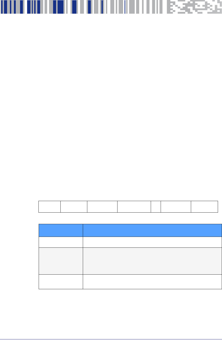
27
Definition of Scanning Angles
Skew, Pitch, Roll Angle testing is based on ISO 15423 specifications
Figure 11. ISO15423 angle definition
Reading distances are measured along Z-axis.
Regulatory
Aiming System (laser) EN/IEC 60825-1:2007 (class 2)
21 CFR 1040 (CDRH) (class II)
Illumination System (white
LEDs) IEC 62471 Exempt risk group
Environmental RoHS compliant
Item Description

Technical Specifications
28
DE2011-DL
Power Consumption Details
While operating, the engine switches between different status conditions.
Each status is characterized by a specific power consumption level.
Assuming the system is at 23°C and all three power supplies are at 3.3V, the
typical current absorption is reported in the table below (engine parameters
set at factory default).
Table 8. Mean power consumption upper limits
<0.2mA
Temperature 23°C
Illumination lamp duration 600us
AIM laser-on duration 8500us
VDD = 3.3V
VDD_SENSOR = 3.3V
VDD_ILLUM = 3.3V
Idle 21mA
Image Acquisition 70mA
Illumination Enabled
lamp duration 600us - factory default 150mA
Illumination Enabled and AIM Enabled
factory default timing 160mA
Maximum Operating Current
AIM on at factory default and
lamp duration 1000us (maximum value)
200mA
Low power
The engine is in sleep (minimum power consumption)
Idle
The engine is active, waiting for commands and ready to start an
acquisition
Running
The engine is acquiring and streaming images to the host. Power
consumption depends on the configuration of the engine
DE2011 status Current
Consumption Conditions
Low power

Integration Guide
29
Appendix B
I2C Command Specifications
This section provides additional information about I2C Commands.
C COMMAND SPECIFICATIONS
•
AIM TIME (0x4E) page 30
•
AIM TOGGLE (0x35) page 30
•
AUTO LOW POWER (0x44) page 30
•
BOOTLOADER START (0x41) page 30
•
CAMERA MODE (0x3B) page 30
•
CAMERA RESET (0x37) page 31
•
CAMERA START (0x38) page 31
•
GET CAMERA PARAM (0x40) page 31
•
GET SENSOR REGISTER (0x31) page 31
•
ILLUMINATION DELAY (0x34) page 32
•
ILLUMINATION ENABLE (0x39) page 32
•
ILLUMINATION TIME (0x48) page 32
•
RESTORE FACTORY DEFAULT (0x23) page 32
•
RUN CMD LIST (0x47) page 32
•
SET AUTO POWER TIME (0x45) page 32
•
SENSOR BINNING (0x3C) page 32
•
SET CAMERA PARAM (0x41) page 33
•
SET COMMAND LIST (0x46) page 33
•
SET LOW POWER (0x3F) page 34
•
SET SENSOR REG (0x30) page 34
I2

I2C Command Specifications
30
DE2011-DL
I2C Command Specifications
This section contains a complete description of the DE2011-DL possible I2C
supported commands in alphabetical order. For a summary list and more
information, see Command Format, starting on page 17
.
AIM TIME (0x4E)
Determines the lighting time of the aiming pattern during
each frame, starting from after the sensor exposure. A
longer period determines a brighter aim pattern.
Accepts values from 0x1 to 0xFF; each unit corresponds
to a 0.5 ms time increment.
If set to 0x0, sets the time to a default value, which can
be also determined by the user modifying the parameter
AIM DURATION (see Table 7 on page 24)
AIM TOGGLE (0x35)
With the value set to 0x01 the aim pattern will turn on
whenever the camera is acquiring images. Setting the
value to 0x00 will always turn it off.
The aim pattern will not be visible in the acquired images.
AUTO LOW POWER (0x44)
Activates system automatic power saving mode, turning
the system into low power mode after a timeout.
When the camera is continuously idle for a time,
previously determined using the SET AUTO POWER TIME
command, the system enters a power reduction state.
When an I2C command is issued the system wakes up and
executes the command.
BOOTLOADER START (0x41)
Stops executing the engine camera application and runs
the engine bootloader. Takes as input the following
signature code: 0xAA, 0x50, 0x5.
CAMERA MODE (0x3B)
Sets up the engine system and the image sensor for
better performance of a specific task: Barcode Decoding,
Image Capture, Motion Detection, Fast High Bin or LCD
screen Read modifying sensor internal register values,
LED illumination and aiming pattern on/off timing.
This command modifies only some key engine and sensor
parameters, leaving others unchanged. The parameters
changed by this command are:
Whichever value is set, for each frame the aim on time might be
automatically trimmed in order to be off during the sensor expo-
sure.

I2C Command Specifications
Integration Guide
31
CAMERA MODE (continued)
ILLUMINATION TIME
ILLUMINATION DELAY
AIM ON TIME
AIM DELAY
IMAGE BINNING
SENSOR CONTEXT
SENSOR AEC MAX EXPOSURE
DESIRED BIN
SENSOR ACTIVE CONTEXT (A/B)
Barcode Decoding
,
Image Capture
and
LCD Screen Read
operate using sensor Context A, while
Motion Detection
and
Fast H
igh Bin
operate using
sensor Context B with a
2xColumn+2xRow binning.
CAMERA RESET (0x37)
Re-initialization of all systems. The camera returns to its
initial state, except for all parameters previously stored in
EEPROM using SET CAMERA PARAM, that will be retained
and will be loaded back at the end of this system reset.
If parameter is 0x00, only the image sensor will be reset.
CAMERA START (0x38)
Starts or stops image acquisition and image
transmission.
After a stop command (CAMERA START with parameter
0x00), the engine begins the procedure for stopping the
image sensor. During this time (at max one frame of
16.6ms) the system will not compute any I2C command.
GET CAMERA PARAM (0x40)
Reads camera system factory parameters or user custom
parameters stored in non-volatile memory. Details can be
found in Table 6 on page 23, and Table 7 on page 24.
GET SENSOR REGISTER (0x31)
Returns the desired register value of the Aptina MT9V024
image sensor. Further details on the sensor can be found
in the MT9V024 manual.
The changes will not be written to non-volatile memory and User
Custom Parameters will NOT be modified by this command.

I2C Command Specifications
32
DE2011-DL
ILLUMINATION DELAY (0x34)
Sets the illumination delay time taking as a starting point
Sensor Exposure start. Accepts values from 0x00 to 0xFF
with a time unit of 30us.
ILLUMINATION ENABLE (0x39)
With the value set to 0x01 the illumination LEDs will turn
on whenever the camera is acquiring images. Setting the
value to 0x00 will always turn it off.
ILLUMINATION TIME (0x48)
Sets the illumination light duration within each frame,
with a 50us time increment. Values are from 0x00 (0us)
to 0x14 (1ms).
RESTORE FACTORY DEFAULT (0x23)
The following User Custom Parameters values are
restored to their Factory Default:
ILLUMINATION PULSE DURATION
ILLUMINATION DELAY
AIM PULSE DURATION
AIM DELAY
SENSOR AEC MAX EXPOSURE
See Table 7 on page 24 for Factory Default values.
RUN CMD LIST (0x47)
Executes the sequence of commands previously
memorized using the SET CMD LIST command.
SET AUTO POWER TIME (0x45)
Sets the timeout value after which power saving mode is
activated. When camera is idle and AUTO LOW POWER is
active the timer starts counting; whenever any command
is issued the timer resets.
SENSOR BINNING (0x3C)
Modifies sensor register values for image binning:
merging of adjacent pixels with a consequent change of
resolution and variation in output image signals timing.
A bin of x means that x adjacent pixels are merged
(column or row wise), which means that resolution is
(current resolution)/x (on columns for “Column Binning”
or rows for “Row Binning”). Column Binning also divides
pixel clock frequency by x; row binning also multiplies by
x the camera FPS. Binning is applied to the context A or B,
depending on the current active CAMERA MODE (see
command).

I2C Command Specifications
Integration Guide
33
SENSOR BINNING (continued)
The parameter to be sent can be calculated by summing
the number corresponding to the desired Row Binning,
with the number corresponding to the desired Column
Binning, as in the following table:
Row Binning codes:
0x00 = No Row Bin
0x01 = Row Bin 2
0x02 = Row Bin 4
Column Binning codes:
0x00 = No Column Bin
0x04 = Column Bin 2
0x08 = Column Bin 4
Total Image Binning code = (Row Binning code) +
(Column Binning code). A value of “0” disables Binning.
SET CAMERA PARAM (0x41)
Writes the chosen parameter to the camera’s non-volatile
memory area User Custom Parameters. The stored values
will be used as new defaults, replacing the Factory
Default Values. For example, after a camera reset or
startup the user custom values will be applied. The
customizable parameters are:
ILLUMINATION PULSE DURATION
ILLUMINATION DELAY
AIM PULSE DURATION
AIM DELAY
SENSOR AEC MAX EXPOSURE
See Table 7 on page 24 for details.
To roll back the memory to factory default (losing the
custom values), use RESTORE FACTORY DEFAULT
command.
SET COMMAND LIST (0x46)
Sets a user-defined sequence of commands to be
executed using RUN CMD LIST. Up to ten lists (0 to 9) can
be saved; each can store up to 150 bytes (command
codes + command parameters). NAK response is issued
by the camera if limits are not respected.
Possible commands for the list are:
AIM TOGGLE
CAMERA START
ILLUMINATION ENABLE
SET SENSOR REG
Command format:
(0x46)(List#)(Total Length) + (Command1 Length)
(Command1) +[…]+(Command n Length) (Command n)
+(Checksum)
Where “command x” is the normal byte sequence of the
desired command.

I2C Command Specifications
34
DE2011-DL
SET LOW POWER (0x3F)
Activates system power saving mode. This command can
only be used when the camera is stopped (no image
acquisition is in progress), since it puts both the
microcontroller and the image sensor into sleep mode.
The system wakes up and returns to normal power mode
each time a command is issued.
SET SENSOR REG (0x30)
Stores the new chosen value for the desired register of
the Aptina MT9V024 image sensor. Further details on the
sensor can be found on the MT9V024 manual.
Modifying registers manually bypasses the engine system
control over the sensor. This could cause the image
sensor to behave in a way that conflicts with the engine
system working setup and normal operation.
CAUTION
Unpredictable camera behavior may occur.
Integration Guide
35
Appendix C
Engine Video Format
This appendix describes details related to the video port of the engine, the
image format and the related timing.
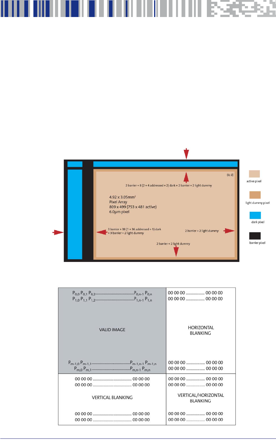
Sensor Data Format
The Datalogic DE2011-DL engine is based on the WVGA monochrome image
sensor.
Figure 12 and Figure 13 below show the pixel array description and the spa-
tial illustration of image readout.
Figure 12. Pixel array description
Figure 13. Spatial illustration of image readout characterizing the progressive
scan mode
Engine Video Format
36
DE2011-DL
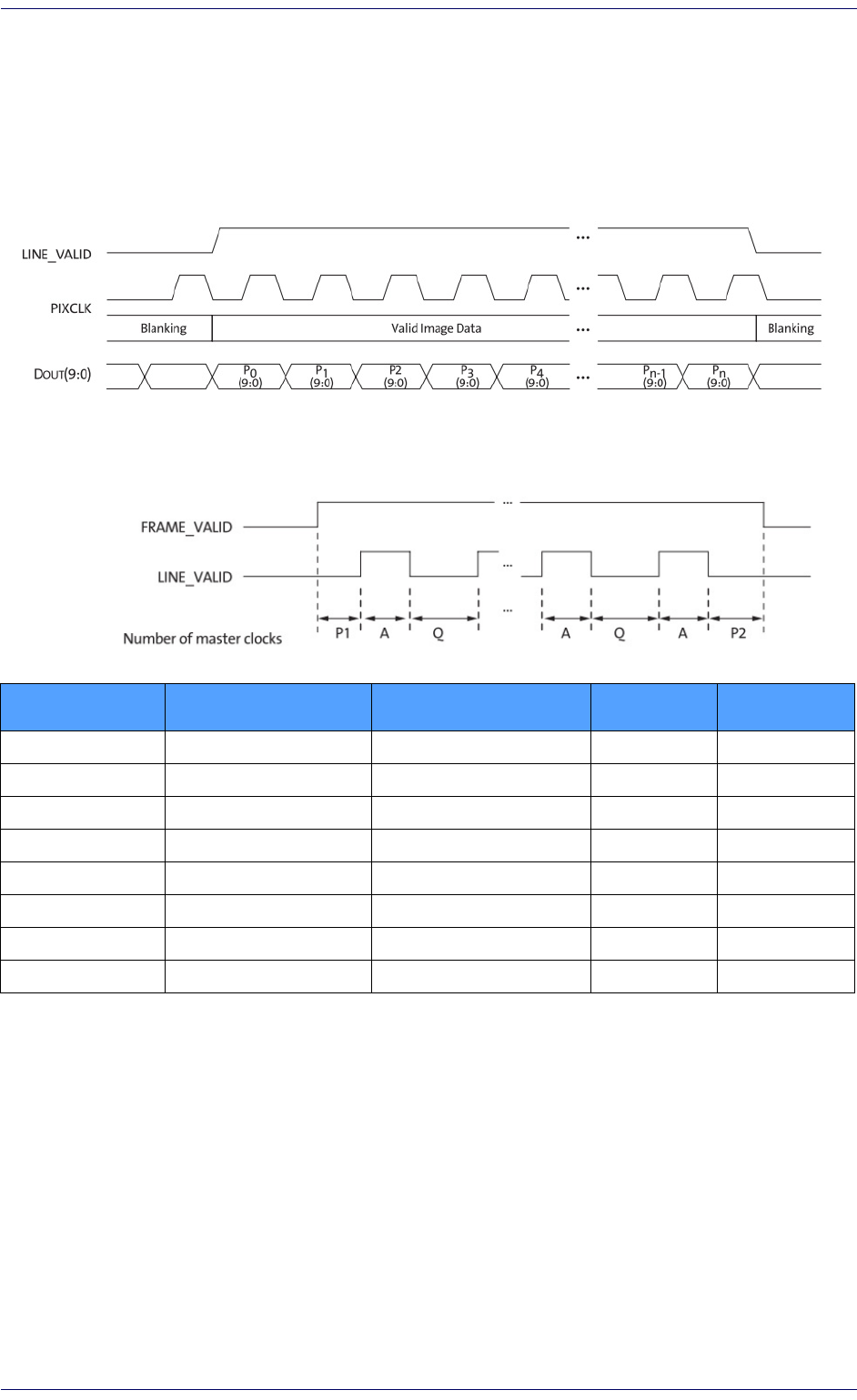
Output Data Timing
The data output of the sensor is synchronized with the PIXCLK output.
When LINE_VALID (LV) is HIGH, one 10-bit pixel datum is output every PIX-
CLK period. Figure 14 shows an example of pixel data timing, and Figure 15
shows basic timing for a complete frame readout.
Figure 14. Timing example of pixel data
Figure 15. Row Timing and FRAME_VALID/LINE_VALID Signals
AActive data time Sensor register defined 752 28.20us
P1 Frame start blanking Sensor register defined 71 2.66us
P2 Frame end blanking 23 (fixed) 23 0.86us
QHorizontal blanking Sensor register defined 94 3.52us
A+Q Row time A+Q 846 31.72us
VVertical blanking Sensor register defined 37,228 1.39ms
Nrows(A+Q) Frame valid time Sensor register defined 406,080 15.23ms
FTotal frame time V+(Nrows(A+Q)) 443,308 16.62ms
Sensor Registers Settings
For information on register settings, refer to the Aptina MT9V024 mono-
chrome WVGA Image Sensor Datasheet, available at http://www.aptina.com.
Parameter Name Equation Pixel Clock Timing at
26,66MHz
Integration Guide
37
Appendix D
Accessories
This section provides information about scan engine accessories and their
installation.
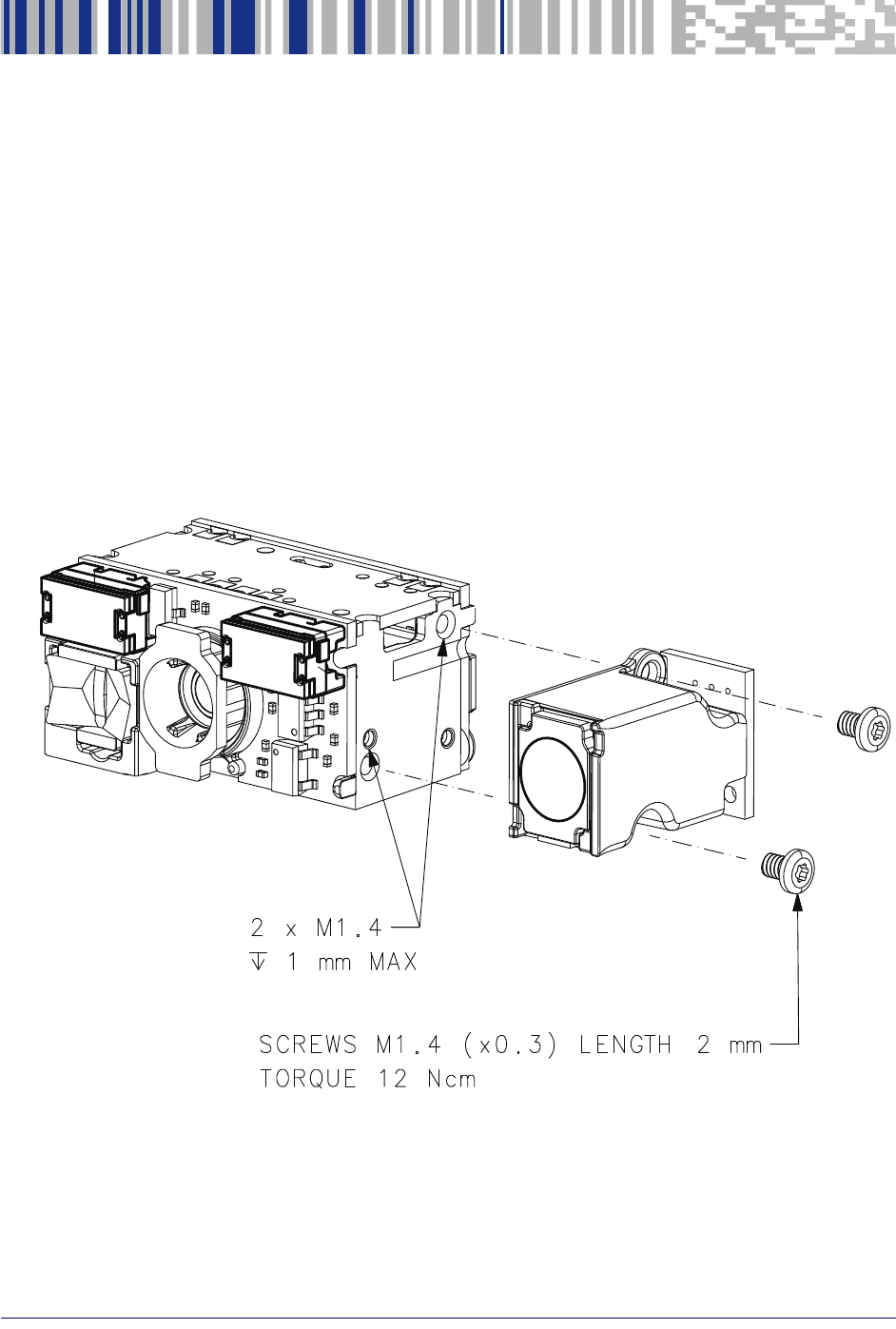
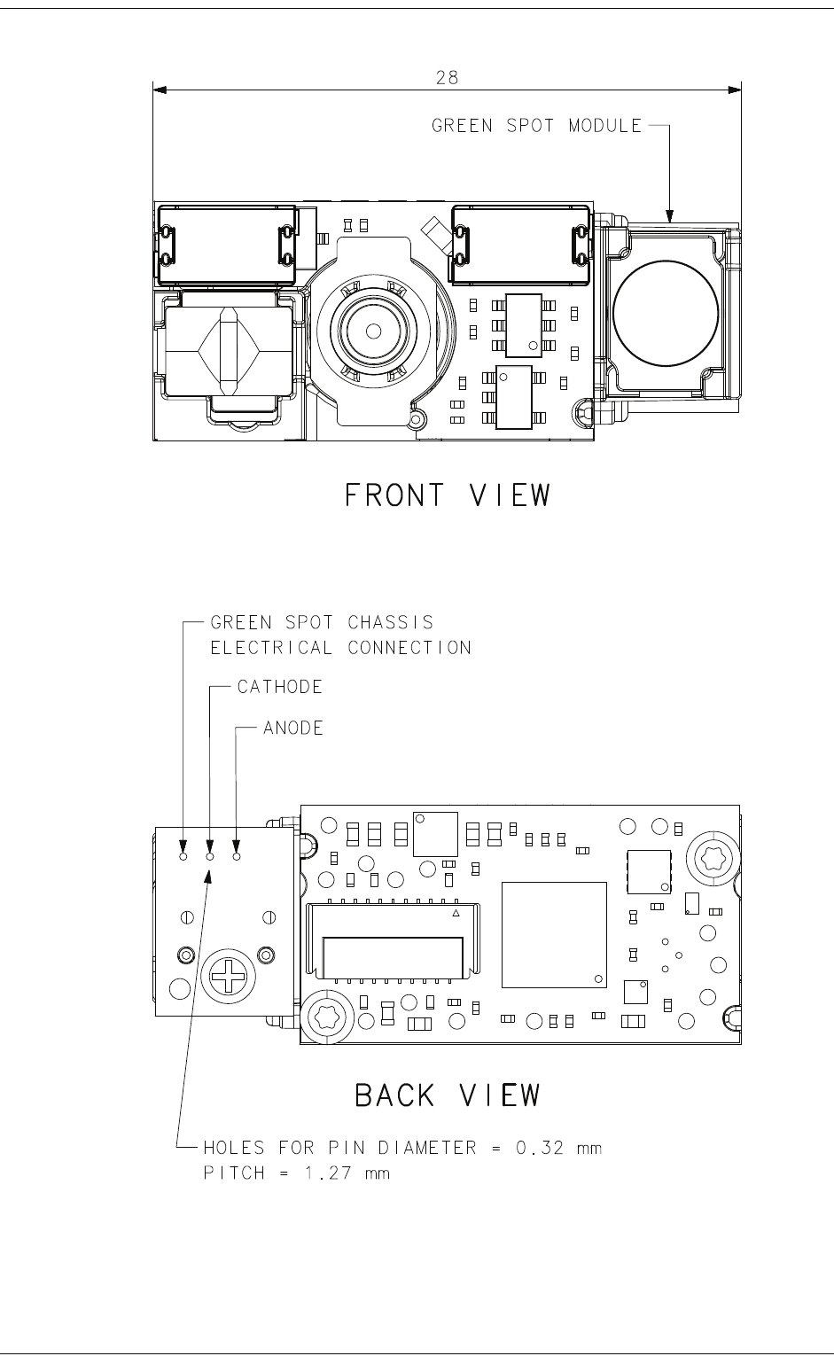
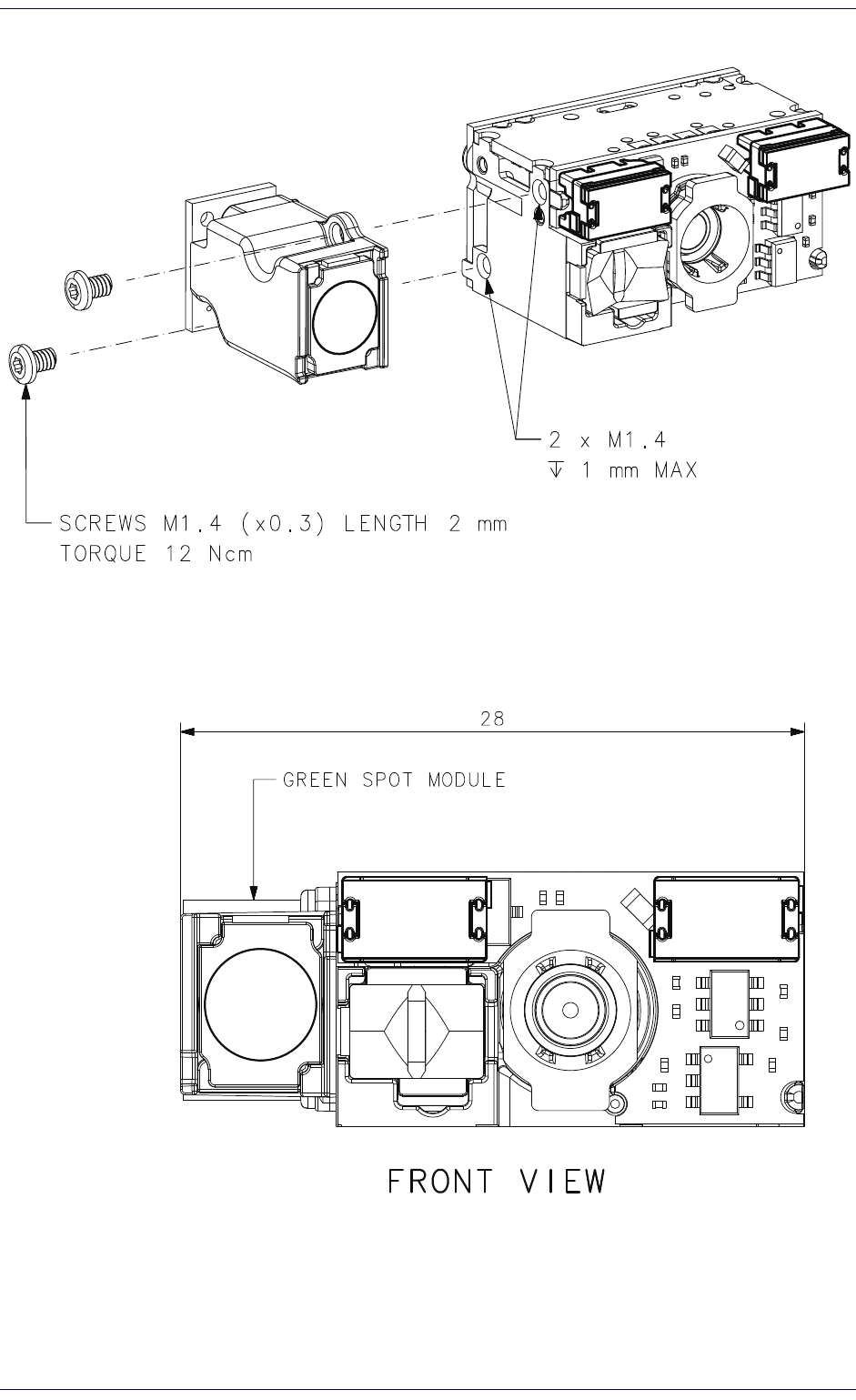
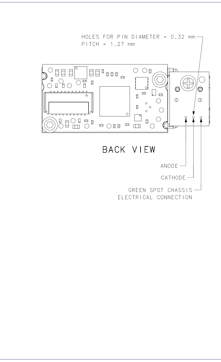
Green Spot Projector
Optionally, a green spot projector can be installed on either the left or right
side of the engine. The following drawings provide information for mount-
ing.
Green Spot Projector - Left side mounting
Accessories
38
DE2011-DL
Left side mounting (continued)
Green Spot Projector
Integration Guide
39
Green Spot Projector - Right side mounting
Accessories
40
DE2011-DL
Right side mounting (continued)

Datalogic ADC, Inc.
959 Terry Street
|
Eugene
|
OR 97402
|
USA
Telephone: (1) 541-683-5700
|
Fax: (1) 541-345-7140
©2014 Datalogic, Inc. All rights reserved. Datalogic and the Datalogic
logo are registered trademarks of Datalogic S.p.A. in many countries,
including the U.S.A. and the E.U.
www.datalogic.com
820061590 (Rev A) May 2014