Datalogic S r l 0156 JOYA X1 PLUS Mobile Computer User Manual
Datalogic ADC S.r.l. JOYA X1 PLUS Mobile Computer
UserManual.wiki
>
Datalogic S r l
>
0156 User Manual
user manual
Navigation menu
Upload a User Manual
Namespaces
Wiki Guide
HTML
PDF
Info
Views
User Manual
Discussion / Help
Navigation
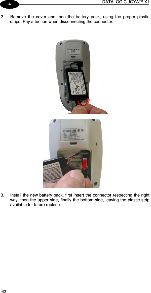
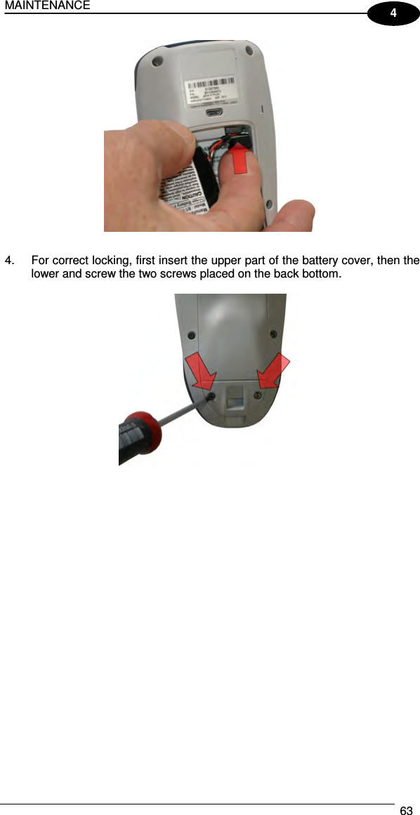
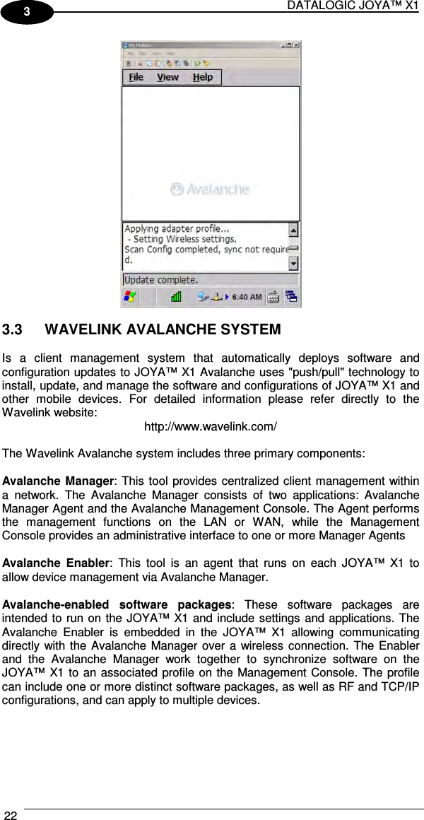
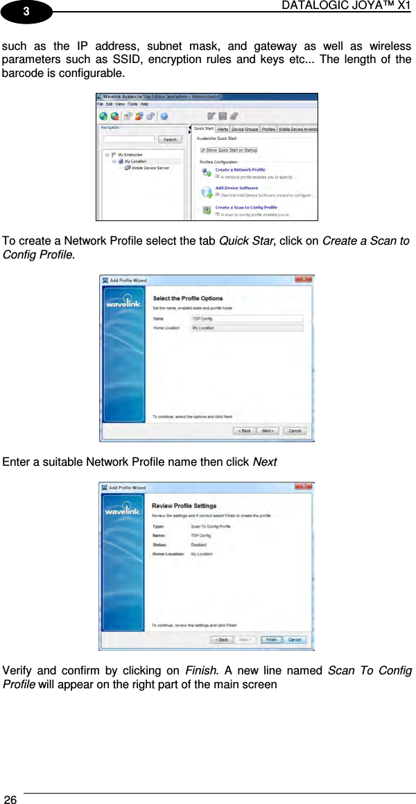
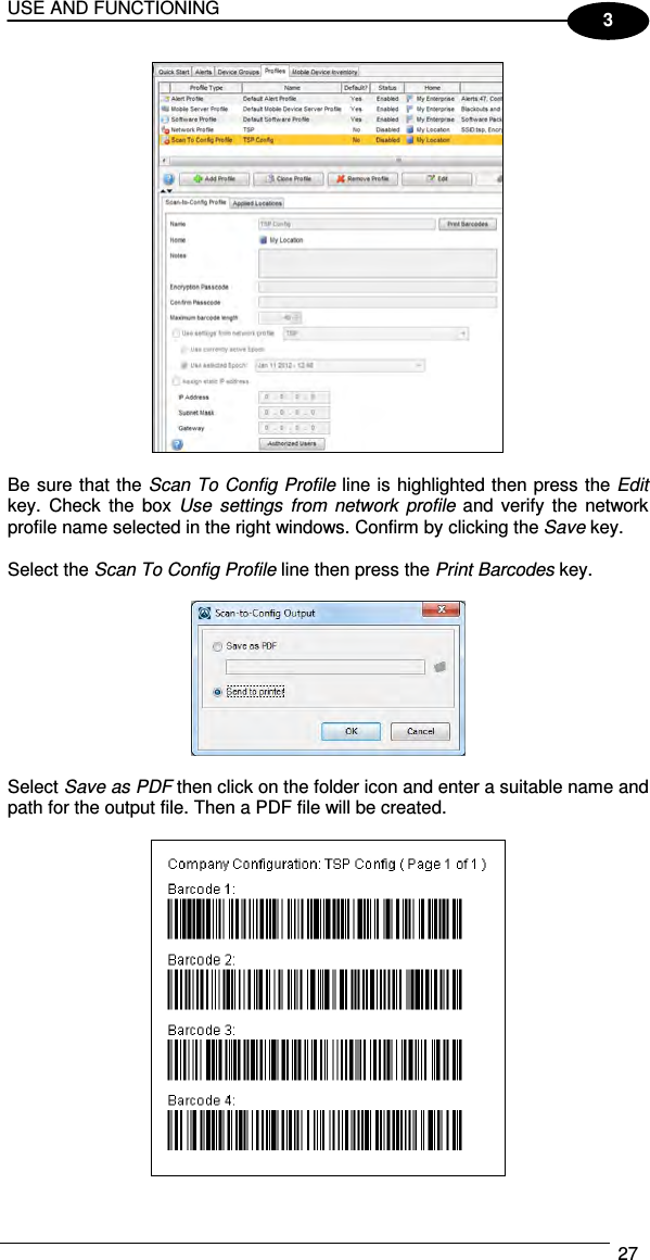
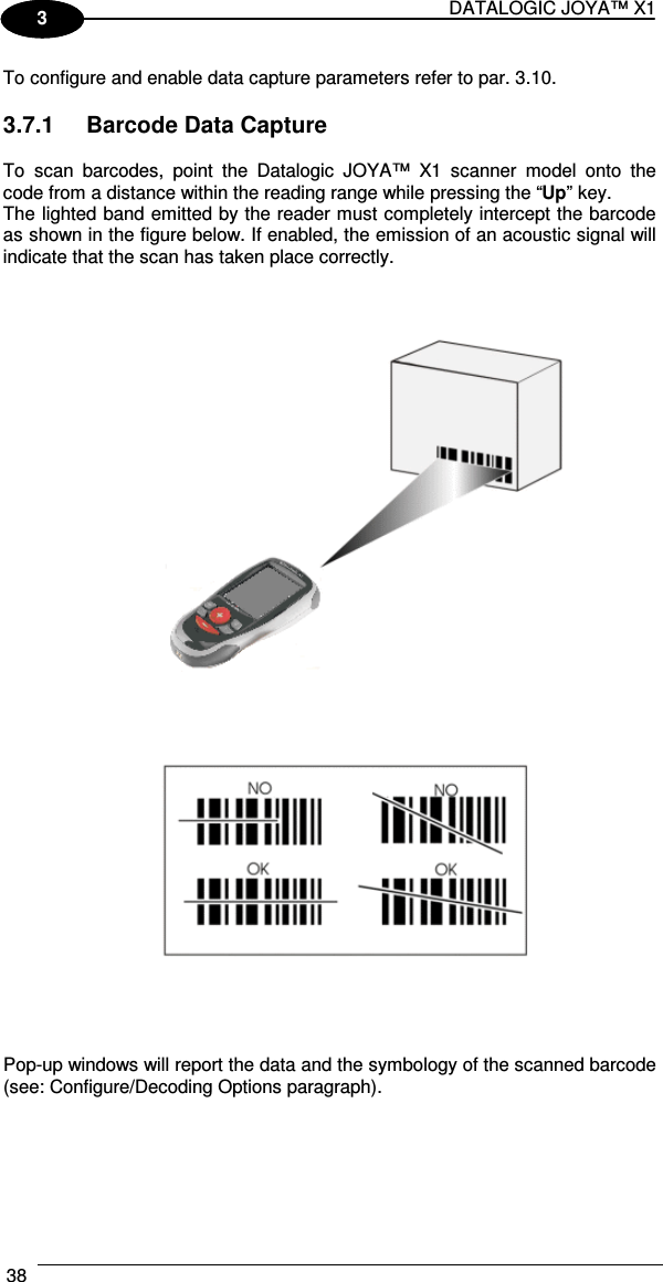
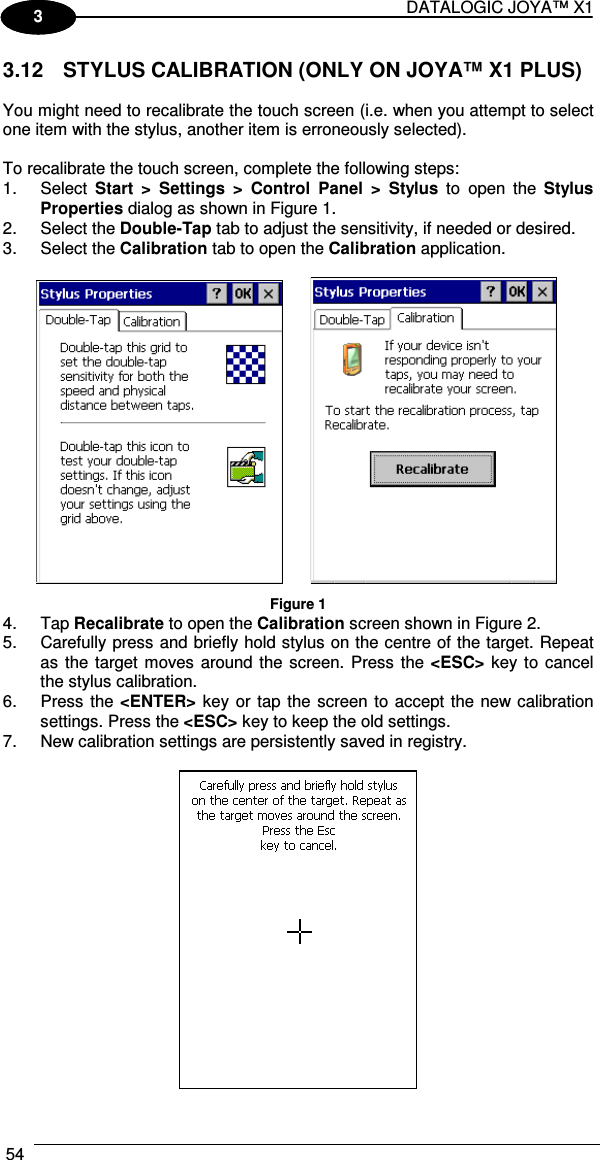
![INTRODUCTION 7 1 • The portable device Joya™ X1 from Datalogic is in compliance with the IC RSS 102 Issue 4 [RSS 102] and Federal Communications Commission (FCC) Guidelines [OET 65] for uncontrolled exposure. SAR assessment in body worn was conducted with the back of the device in direct contact against the flat phantom. • The portable device Joya ™ X1 from Datalogic is in compliance European Standard EN 50566: Product standard to demonstrate compliance of radio frequency fields from handheld and body-mounted wireless communication devices used by the general public (30 MHz - 6 GHz) FCC COMPLIANCE - JOYA CRADLE DISPENSER Modifications or changes to this equipment without the expressed written approval of Datalogic could void the authority to use this equipment. The device complies with PART 15 of the FCC Rules. Operation is subject to the following two conditions: (1) This device may not cause harmful interference, and (2) this device must accept any interference received, including interference which may cause undesired operation. This equipment has been tested and found to comply with the limits for a Class A digital device, pursuant to part 15 of the FCC Rules. These limits are designed to provide reasonable protection against harmful interference when the equipment is operated in a commercial environment. This equipment generates, uses, and can radiate radio frequency energy and, if not installed and used in accordance with the instruction manual, may cause harmful interference to radio communications. Operation of this equipment in a residential area is likely to cause harmful interference in which case the user will be required to correct the interference at his own expense. INDUSTRY CANADA COMPLIANCE – JOYA CRADLE DISPENSER This Class A digital apparatus complies with Canadian ICES-003. Cet appareil numérique de la classe A est conforme à la norme NMB-003 du Canada. This EUT is compliant with SAR for general population/uncontrolled exposure limits in IC RSS-102 and had been tested in accordance with the measurement methods and procedures specified in IEEE 1528. This equipment should be installed and operated with minimum distance of 0 cm between the radiator & your body. Le présent appareil est conforme aux CNR d'Industrie Canada applicables aux appareils radio exempts de licence. L'exploitation est autorisée aux deux conditions suivantes : (1) l'appareil ne doit pas produire de brouillage, et (2) l'utilisateur de l'appareil doit accepter tout brouillage radioélectrique subi, même si le brouillage est susceptible d'en compromettre le fonctionnement.](https://usermanual.wiki/Datalogic-S-r-l/0156/User-Guide-2230573-Page-13.png)
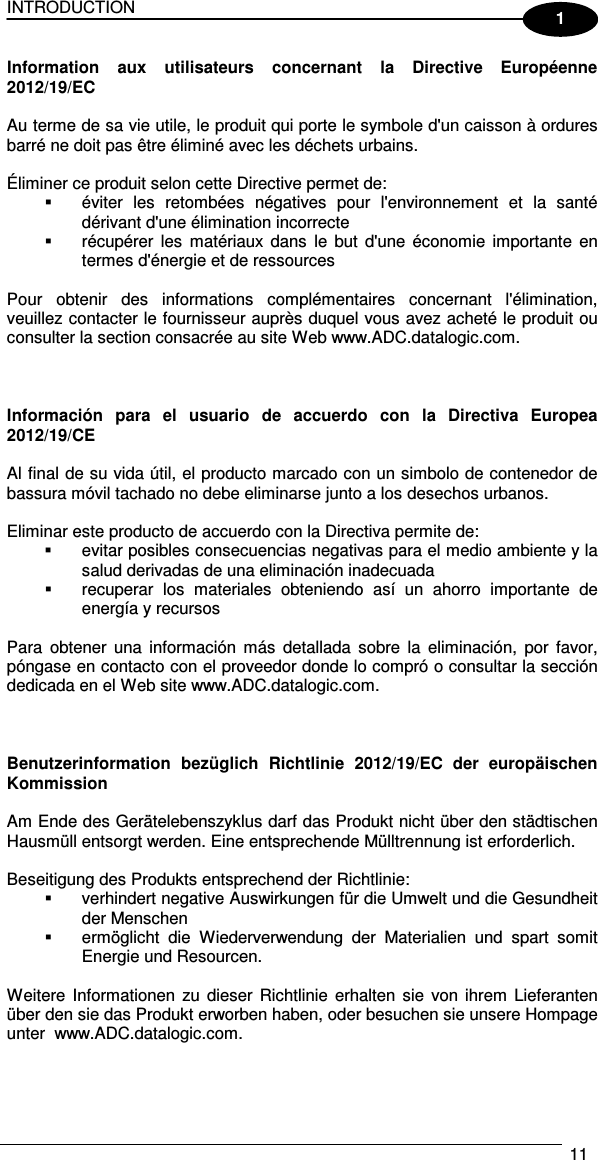
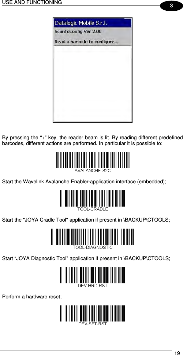
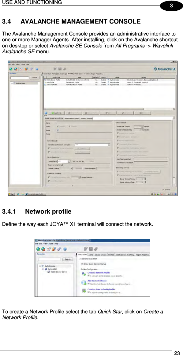
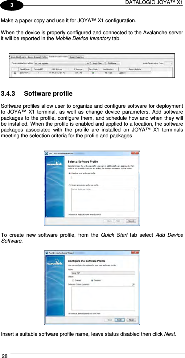
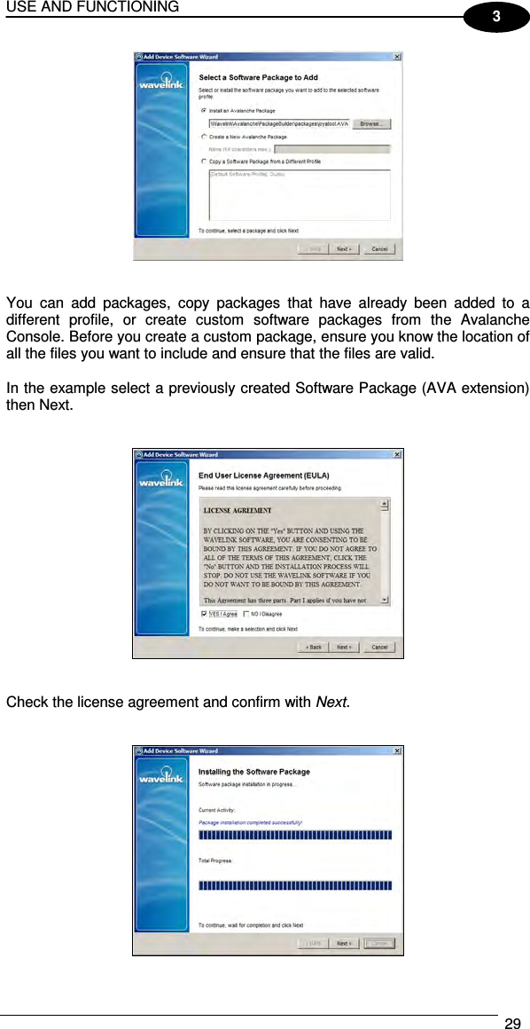
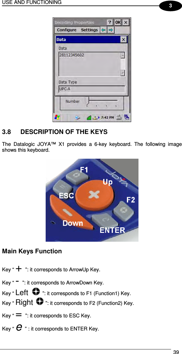
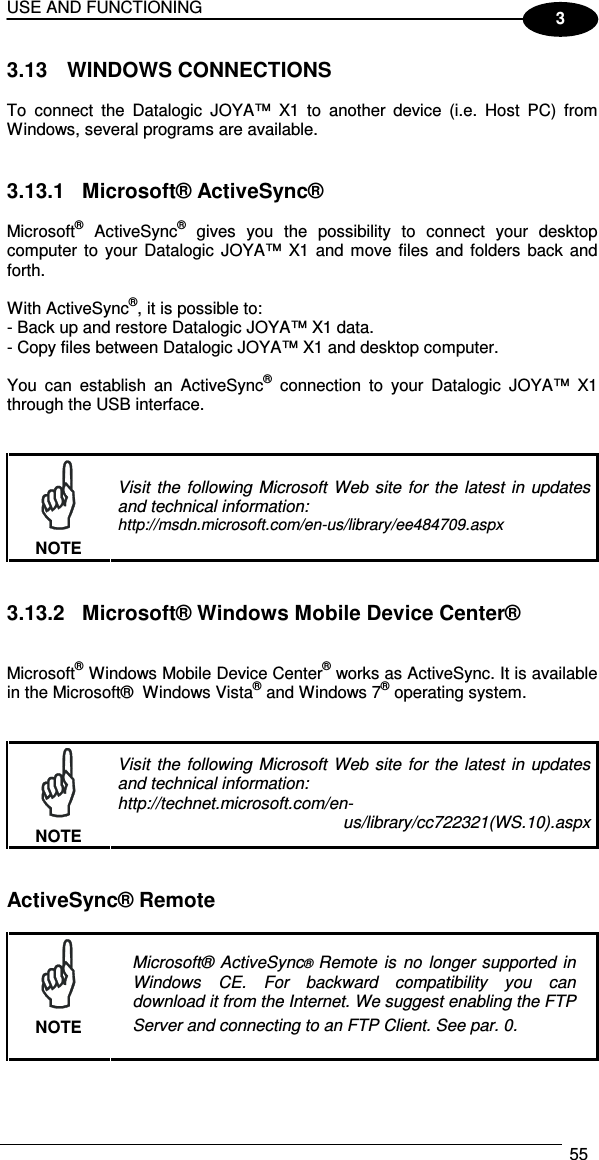
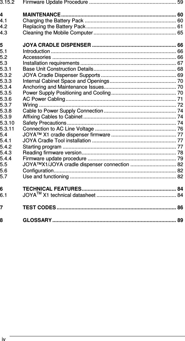
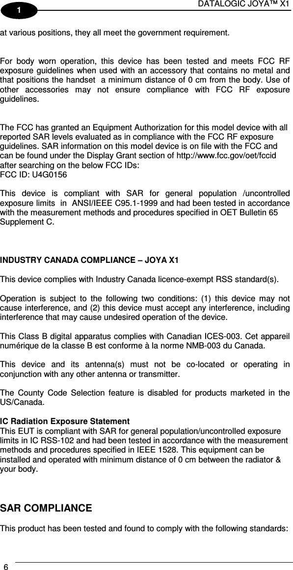
![DATALOGIC JOYA™ X1 56 1 3 3.13.3 FTP Server Setup The Datalogic JOYA™ X1 Operating System includes a File Transfer Protocol (FTP) server. FTP is used for copying files to and from remote computer systems over a network using TCP/IP. You can establish a connection to your Datalogic JOYA™ X1 using its FTP Server through the WLAN using the WiFi radio Proceed as follows: 1. Create a registry file (extension .reg) to setup and enable FTP Server communication. A simple example file for “anonymous” logon is given below: REGEDIT4 [HKEY_LOCAL_MACHINE\Comm\FTPD] "DefaultDir"="\\" "AllowAnonymousUpload"=dword:00000001 "UseAuthentication"=dword:00000000 "BaseDir"="\\" "IsEnabled"=dword:00000001 "LogSize"=dword:00001000 "DebugOutputMask"=dword:00000017 "DebugOutputChannels"=dword:00000002 "IdleTimeout"=dword:0000012c "AllowAnonymous"=dword:00000001 "AllowAnonymousVroots"=dword:00000001 2. Copy this file to the Datalogic JOYA™ X1 using ActiveSync®. 3. Launch the .reg file from the Datalogic JOYA™ X1 4. Perform a warm boot on the Datalogic JOYA™ X1 5. From the PC > Explorer address bar (or running an FTP Client from the PC), enter the Datalogic JOYA™ X1 IP address. NOTE For more information on FTP Client/Server connections refer to the following web page: http://msdn2.microsoft.com/en-us/library/aa922316.aspx.](https://usermanual.wiki/Datalogic-S-r-l/0156/User-Guide-2230573-Page-62.png)
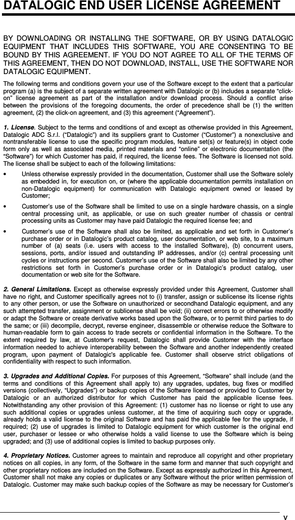
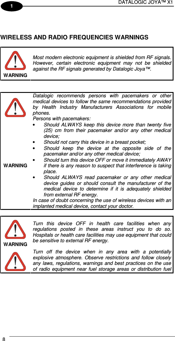
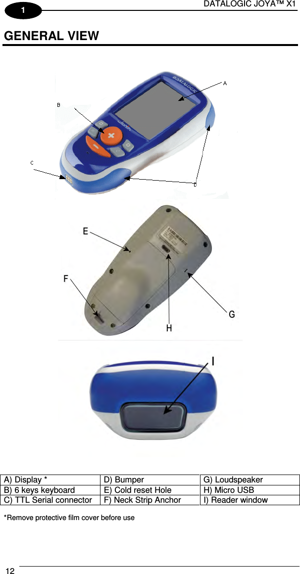
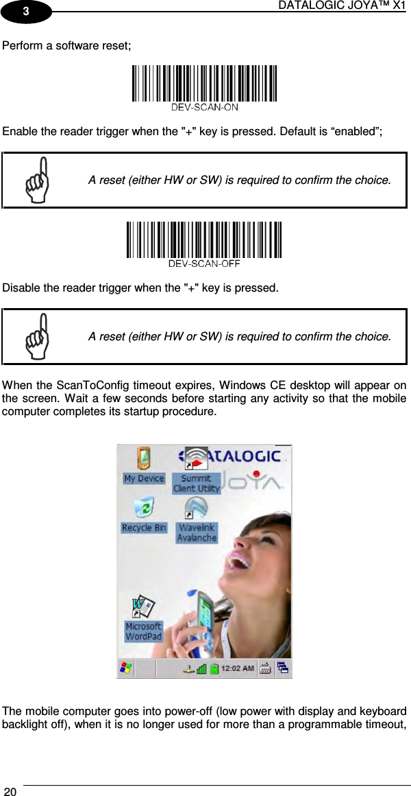
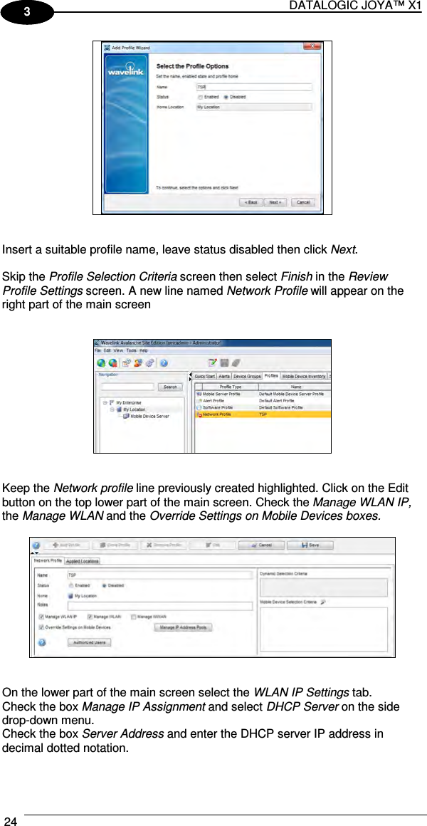
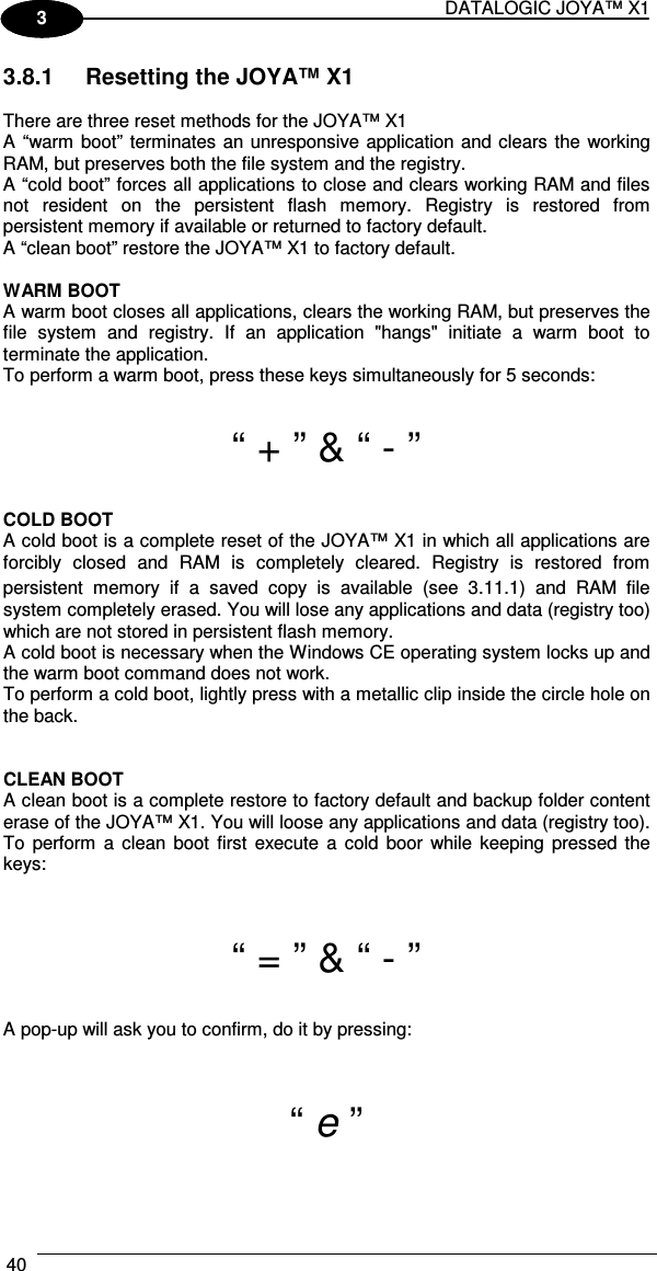
![USE AND FUNCTIONING 57 3 3.14 BACKUP DIRECTORY FILE MANAGEMENT All of the Windows CE 6.0 system files reside in RAM (volatile memory) except for the Backup directory, which resides in FLASH (non-volatile memory). Therefore the contents of the Backup directory are persistent even if the mobile computer is rebooted or the battery pack is changed. You can save your more important files that you don't want to lose due to mobile computer reboot, in the Backup directory or create a sub-directory within Backup. Even though the Windows Directory resides in RAM, it often contains files or sub-directories created by the user or by installation programs that you don't want to lose at re-boot. To keep these files persistent it is necessary to copy them to the directory \Backup\Windows. This directory doesn't exist originally (only Backup exists), and therefore it must be created. At the next cold boot, before activating the shell, Windows CE 6.0 will copy the contents including all sub-directories of \Backup\Windows to \Windows. Likewise, to maintain files that must be run at Windows CE 6.0 startup, (i.e. .exe, .lnk, .vb, .htm, etc.), it is necessary to copy them to the directory \Backup\Startup. This directory does not exist originally (only Backup exists), and therefore it must be created. The applications programs will be run after any type of re-boot (both software and cold boot). However, since file system persistence is performed after the “\BACKUP\Startup” folder execution, for those programs which depends upon the DLLs and resources copied from “\BACKUP\Windows” to “\Windows” during the cold-boot, the “\BACKUP\Windows\dl_startup” folder is to be preferred to execute programs and applications, since the execution follows the file system restore (and no DLL and resource dependence failure will occur). As an alternative to the Safe Setup function, it is possible to copy the .cab files to the directory \Backup\Cabfiles (the Cabfiles sub-directory doesn't exists originally and must therefore be created) and perform a mobile computer cold boot to have the application installed. Once these files are copied to the directory \Backup\Cabfiles, the application will be run after each re-boot. From the second cold boot on, a message may be displayed such as "<application name> is already installed. Reinstall?". This message blocks the boot process. Press the [Enter] key to continue the system initialization. In the JOYA™ X1 Plus, a 4GB DS type card is available as permanent general purposes storage device (path = \Storage Card).](https://usermanual.wiki/Datalogic-S-r-l/0156/User-Guide-2230573-Page-63.png)