Datalogic S r l DLX3G WWAN 3G Module User Manual DLX3G 2 20160801
Datalogic ADC S.r.l. WWAN 3G Module DLX3G 2 20160801
UserManual.wiki
>
Datalogic S r l
>
DLX3G User Manual
>
Users Manual
Contents
1.
Users Manual
2.
Users Manual_Statement
Users Manual
Navigation menu
Upload a User Manual
Namespaces
Wiki Guide
HTML
PDF
Info
Views
User Manual
Discussion / Help
Navigation
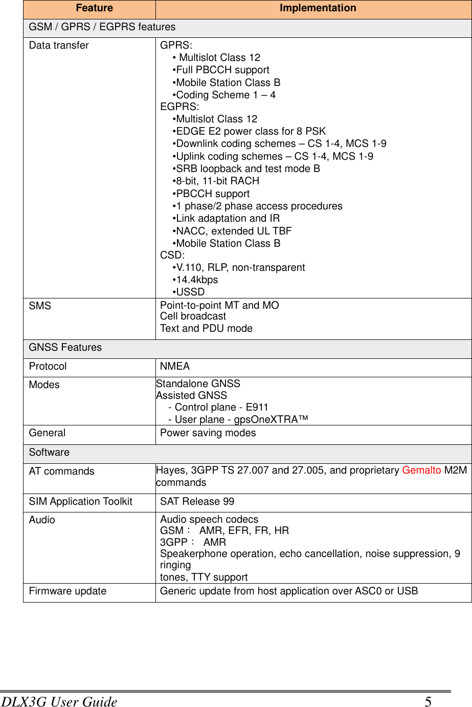
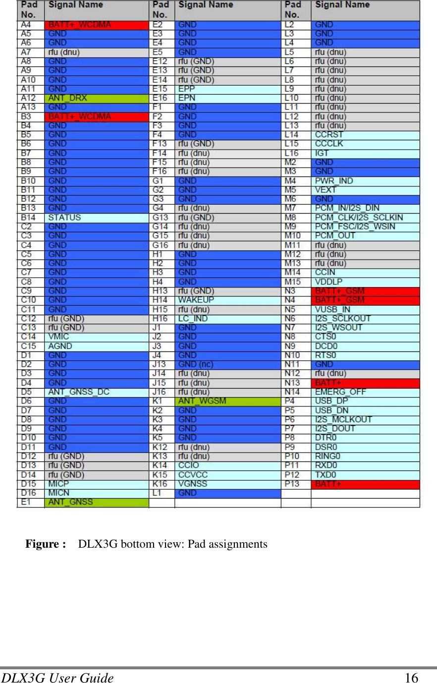
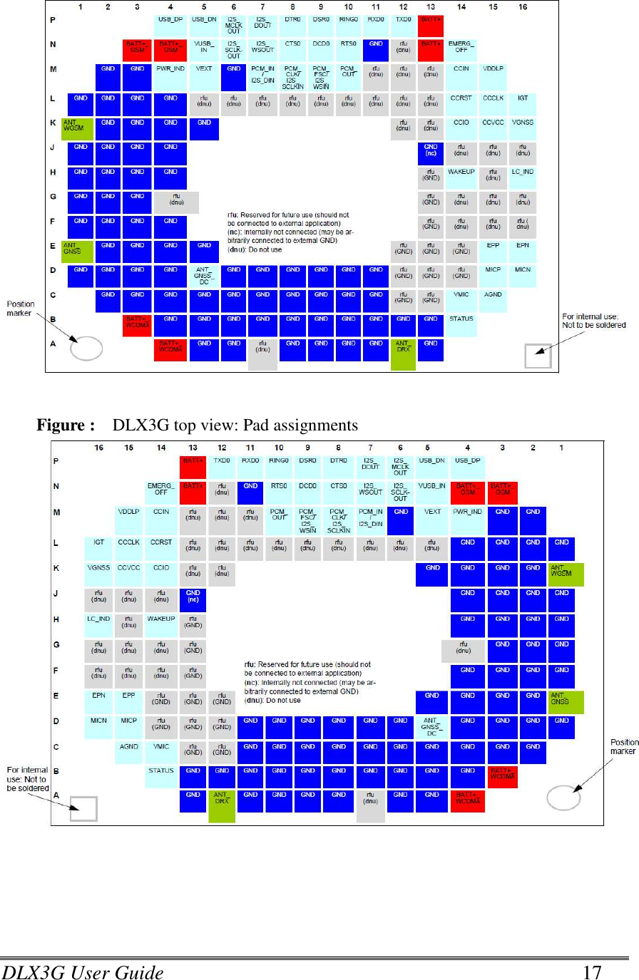
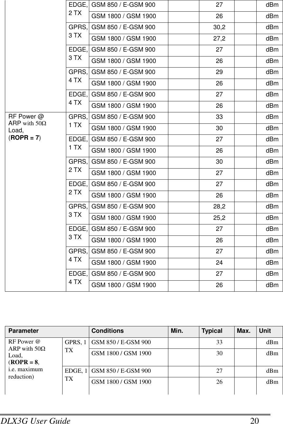
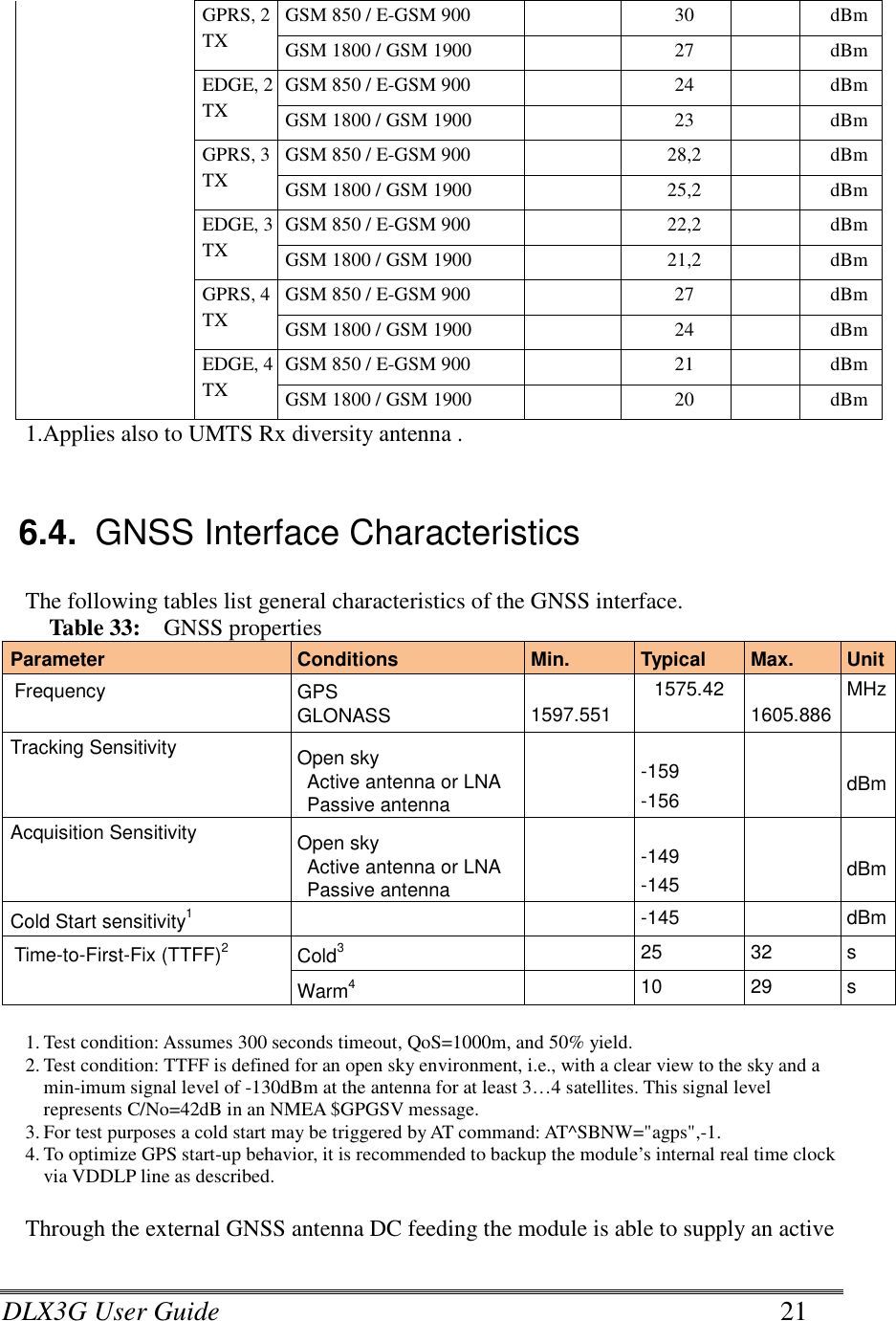
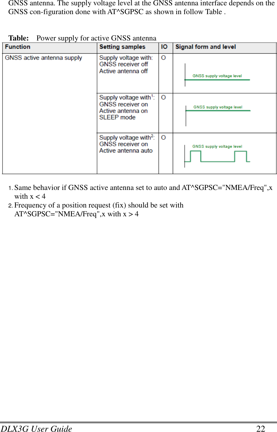
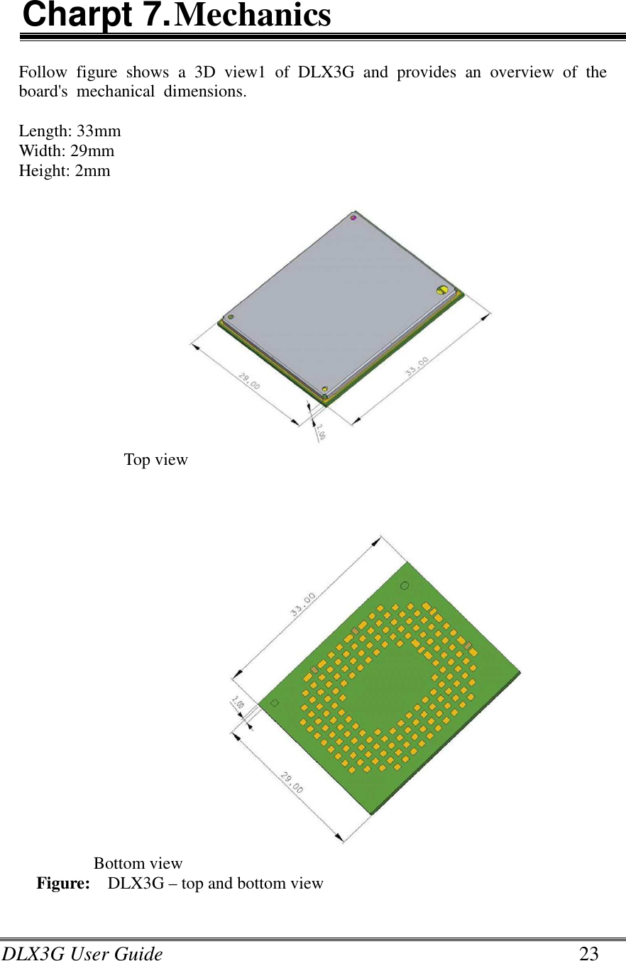
![DLX3G User Guide 6 Feature Implementation Interfaces Module interface Surface mount device with solderable connection pads (SMT application interface). Land grid array (LGA) technology ensures high solder joint reliability and provides the possibility to use an optional module mounting socket. For more information on how to integrate SMT modules see also [7]. This application note comprises chapters on module mounting and application layout issues as well as on additional SMT application development equipment. Antenna 50Ω Main GSM/UMTS antenna, UMTS diversity antenna, GNSS antenna (active/passive) USB USB 2.0 High Speed (480Mbps) device interface, Full Speed (12Mbps) compliant Serial interface ASC0: •8-wire modem interface with status and control lines, unbalanced, asynchronous •Adjustable baud rates from 9,600bps up to 921,600bps •Supports RTS0/CTS0 hardware flow control •Multiplex ability according to GSM 07.10 Multiplexer Protocol UICC interface Supported chip cards: UICC/SIM/USIM 3V, 1.8V Status Signal line to indicate network connectivity state Audio 1 analog interface with microphone feeding 1 digital interface: PCM or I2S USB audio Power on/off, Reset Power on/off Switch-on by hardware signal IGT Switch-off by AT command (AT^SMSO) Automatic switch-off in case of critical temperature or voltage conditions Reset Orderly shutdown and reset by AT command Emergency-off Emergency-off by hardware signal EMERG_OFF if IGT is not active Special Features Phonebook SIM and phone TTY/CTM support Integrated CTM modem Emergency Call Handling EU eCall 3GPP Release 10 compliant ERA GLONASS compliant RLS Monitoring Jamming Detection Antenna SAIC (Single Antenna Interference Cancellation) / DARP (Downlink Advanced Receiver Performance) Rx diversity (receiver type 3i - 16-QAM)](https://usermanual.wiki/Datalogic-S-r-l/DLX3G.Users-Manual/User-Guide-3082461-Page-6.png)