Datalogic S r l DLX3G WWAN 3G Module User Manual DLX3G 2 20160801
Datalogic ADC S.r.l. WWAN 3G Module DLX3G 2 20160801
Contents
- 1. Users Manual
- 2. Users Manual_Statement
Users Manual
DLX3G User Guide 1
DLX3G
Hardware Interface Description
Version: 0.1

DLX3G User Guide 2
Table of Contents
Charpt 1. Regulatory Information ............................................................................ 3
1.1. SAR requirements specific to portable mobiles .............................................. 3
Charpt 2. Product Concept .......................................................................................... 4
2.1. Key Features at a Glance ................................................................................ 4
2.2. DLX3G System Overview .............................................................................. 7
Charpt 3. Application Interface .................................................................................. 8
3.1. Operating Modes ............................................................................................. 8
Charpt 4. GNSS Receiver ........................................................................................... 9
Charpt 5. Antenna Interfaces ................................................................................. 10
5.1. GSM/UMTS Antenna Interface .................................................................... 10
5.2. Antenna Installation .......................................................................................11
Charpt 6. Electrical and Radio Characteristics ......................................................... 13
6.1. Operating Temperatures ................................................................................ 13
6.1.1. Temperature Allocation Model ......................................................... 14
6.2. Pad Assignment and Signal Description ....................................................... 14
6.3. RF Antenna Interface Characteristics ........................................................... 18
6.4. GNSS Interface Characteristics .................................................................... 21
Charpt 7. Mechanics ................................................................................................. 23
Charpt 8. Reference Approval ............................................................................... 24
8.1. Compliance with FCC and IC Rules and Regulations .................................. 24

DLX3G User Guide 3
Charpt 1. Regulatory Information
1.1. SAR requirements specific to portable mobiles
Mobile phones, PDAs or other portable transmitters and receivers incorporating
a GSM module must be in accordance with the guidelines for human exposure
to radio frequency energy. This requires the Specific Absorption Rate (SAR) of
portable DLX3G based applications to be evaluated and approved for
compliance with national and/or international regulations.
Since the SAR value varies significantly with the individual product design
manufacturers are advised to submit their product for approval if designed for
portable use. For US and European markets the relevant directives are
mentioned below. It is the responsibility of the manufacturer of the final product
to verify whether or not further standards, recommendations or directives are in
force outside these areas.
Products intended for sale on US markets
ES 59005/ANSI C95.1 Considerations for evaluation of human exposure to
electromagnetic fields (EMFs) from mobile
telecommunication equipment (MTE) in the frequency
range 30MHz - 6GHz
Products intended for sale on European markets
EN 50360 Product standard to demonstrate the compliance of
mobile phones with the basic restrictions related to
human exposure to electromagnetic fields (300MHz -
3GHz)
IMPORTANT:
Manufacturers of portable applications based on DLX3G modules are required
to have their final product certified and apply for their own FCC Grant and
Industry Canada Certificate relat-ed to the specific portable mobile.
DLX3G User Guide 4
Charpt 2. Product Concept
2.1. Key Features at a Glance
Feature Implementation
General
Frequency bands GSM/GPRS/EDGE: Quad band, 850/900/1800/1900MHz
UMTS/HSPA+: Five band, 800/850/900/1900/2100MHz
GSM class Small MS
Output power (according to
Release 99) Class 4 (+33dBm ±2dB) for EGSM850
Class 4 (+33dBm ±2dB) for EGSM900
Class 1 (+30dBm ±2dB) for GSM1800
Class 1 (+30dBm ±2dB) for GSM1900
Class E2 (+27dBm ± 3dB) for GSM 850 8-PSK
Class E2 (+27dBm ± 3dB) for GSM 900 8-PSK
Class E2 (+26dBm +3 /-4dB) for GSM 1800 8-PSK
Class E2 (+26dBm +3 /-4dB) for GSM 1900 8-PSK
Class 3 (+24dBm +1/-3dB) for UMTS 2100, WCDMA FDD BdI
Class 3 (+24dBm +1/-3dB) for UMTS 1900,WCDMA FDD BdII
Class 3 (+24dBm +1/-3dB) for UMTS 900, WCDMA FDD BdVIII
Class 3 (+24dBm +1/-3dB) for UMTS 850, WCDMA FDD BdV
Class 3 (+24dBm +1/-3dB) for UMTS 800, WCDMA FDD BdVI
Power supply 3.3V < V BATT+ < 4.2V
Operating temperature
(board temperature)
Normal operation: -30°C to +85°C
Extended operation: -40°C to +95°C
Physical Dimensions: 33mm x 29mm x 2mm
Weight: approx. 5g
RoHS All hardware components fully compliant with EU RoHS Directive
HSPA features
3GPP Release 6, 7 DL 14.4Mbps, UL 5.7Mbps
UE CAT. 1-12 supported
Compressed mode (CM) supported according to 3GPP TS25.212
UMTS features
3GPP Release 4 PS data rate – 384 kbps DL / 384 kbps UL
CS data rate – 64 kbps DL / 64 kbps UL

DLX3G User Guide 5
Feature Implementation
GSM / GPRS / EGPRS features
Data transfer GPRS:
• Multislot Class 12
•Full PBCCH support
•Mobile Station Class B
•Coding Scheme 1 – 4
EGPRS:
•Multislot Class 12
•EDGE E2 power class for 8 PSK
•Downlink coding schemes – CS 1-4, MCS 1-9
•Uplink coding schemes – CS 1-4, MCS 1-9
•SRB loopback and test mode B
•8-bit, 11-bit RACH
•PBCCH support
•1 phase/2 phase access procedures
•Link adaptation and IR
•NACC, extended UL TBF
•Mobile Station Class B
CSD:
•V.110, RLP, non-transparent
•14.4kbps
•USSD
SMS
Point
-
to
-
point MT and MO
Cell broadcast
Text and PDU mode
GNSS Features
Protocol NMEA
Modes Standalone GNSS
Assisted GNSS
- Control plane - E911
- User plane - gpsOneXTRA™
General Power saving modes
Software
AT commands Hayes, 3GPP TS 27.007 and 27.005, and proprietary Gemalto M2M
commands
SIM Application Toolkit SAT Release 99
Audio Audio speech codecs
GSM: AMR, EFR, FR, HR
3GPP: AMR
Speakerphone operation, echo cancellation, noise suppression, 9
ringing
tones, TTY support
Firmware update Generic update from host application over ASC0 or USB
DLX3G User Guide 6
Feature Implementation
Interfaces
Module interface Surface mount device with solderable connection pads (SMT
application interface).
Land grid array (LGA) technology ensures high solder joint
reliability and provides the possibility to use an optional module
mounting socket.
For more information on how to integrate SMT modules see also [7].
This application note comprises chapters on module mounting and
application layout issues as well as on additional SMT application
development equipment.
Antenna 50Ω Main GSM/UMTS antenna, UMTS diversity antenna, GNSS
antenna (active/passive)
USB USB 2.0 High Speed (480Mbps) device interface, Full Speed
(12Mbps) compliant
Serial interface ASC0:
•8-wire
modem interface with status and control lines, unbalanced,
asynchronous
•Adjustable baud rates from 9,600bps up to 921,600bps
•Supports RTS0/CTS0 hardware flow control
•Multiplex ability according to GSM 07.10 Multiplexer Protocol
UICC interface Supported chip cards: UICC/SIM/USIM 3V, 1.8V
Status Signal line to indicate network connectivity state
Audio
1 analog interface with microphone feeding
1 digital interface: PCM or I
2
S
USB audio
Power on/off, Reset
Power on/off Switch-on by hardware signal IGT
Switch-off by AT command (AT^SMSO)
Automatic switch-off in case of critical temperature or voltage
conditions
Reset Orderly shutdown and reset by AT command
Emergency-off Emergency-off by hardware signal EMERG_OFF if IGT is not active
Special Features
Phonebook SIM and phone
TTY/CTM support Integrated CTM modem
Emergency Call Handling EU eCall 3GPP Release 10 compliant
ERA GLONASS compliant
RLS Monitoring Jamming Detection
Antenna
SAIC (Single Antenna Interference Cancellation) / DARP (Downlink
Advanced Receiver Performance)
Rx diversity (receiver type 3i - 16-QAM)
DLX3G User Guide 7
Feature Implementation
Evaluation kit
Evaluation module DLX3G module soldered onto a dedicated PCB that can be
connected to an adapter in order to be mounted onto the DSB75.
DSB75 DSB75 Development Support Board designed to test and type
approve Gemalto
M2M modules and provide a sample configuration
for application engineering. A special adapter is required to connect
the DLX3G evaluation module to the DSB75.
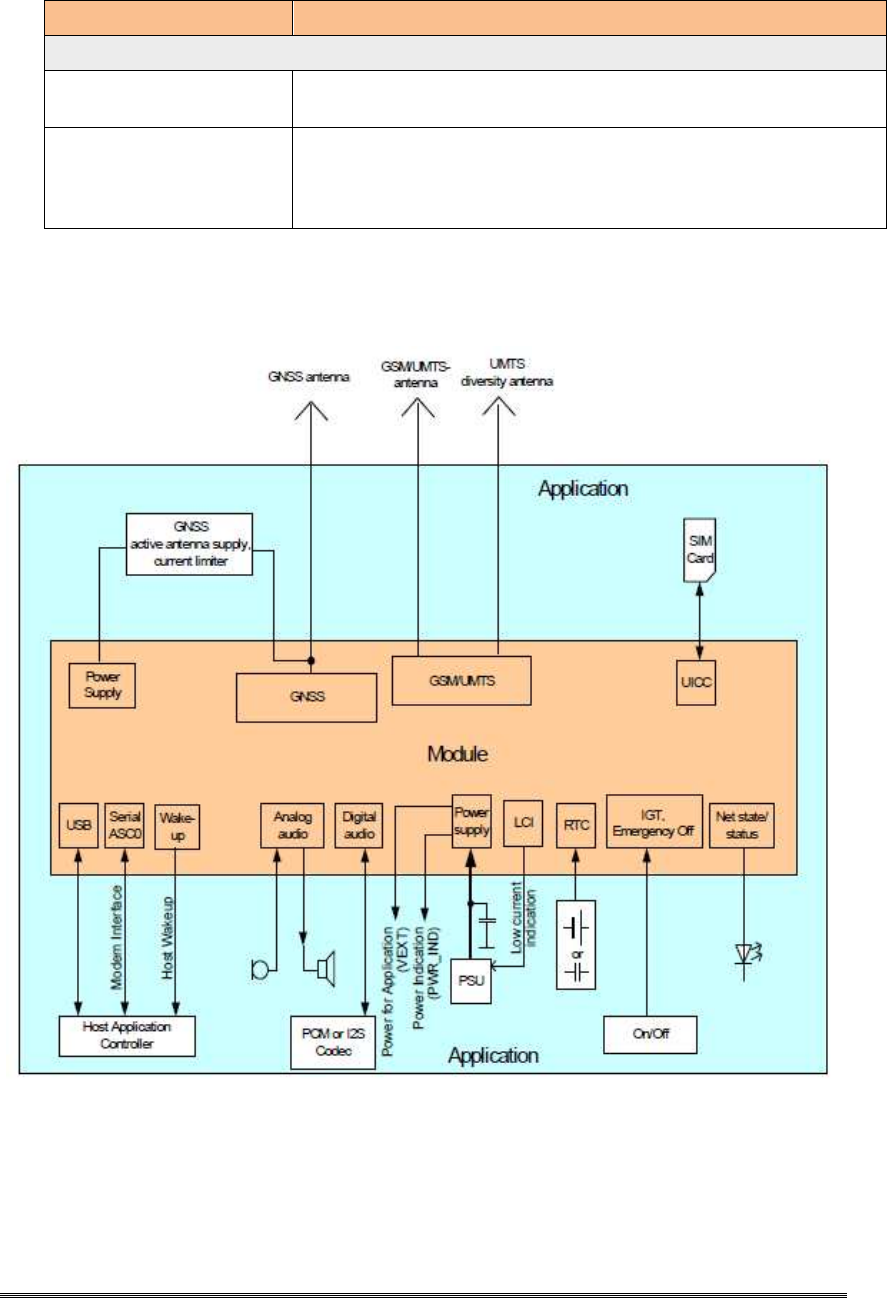
2.2. DLX3G System Overview
DLX3G User Guide 8
Charpt 3. Application Interface
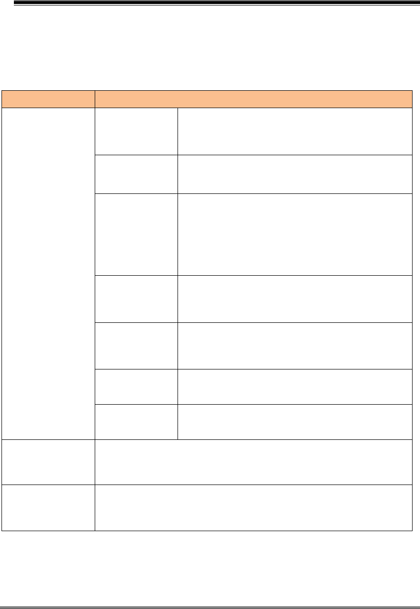
3.1. Operating Modes
The table below briefly summarizes the various operating modes referred to in
the following chapters
Table: Overview of operating modes
Mode Function
Normal
operation GSM /
GPRS / UMTS /
HSPA SLEEP
Power saving set automatically when no call is in
progress and the USB connection is suspended by
host or not present and no active communication via
ASC0.
GSM /
GPRS / UMTS /
HSPA IDLE
Power saving disabled or an USB connection not
suspended, but no call in progress.
GSM TALK/ Connection between two subscribers is in progress.
Power consumption depends on the GSM network
coverage and several connection settings (e.g. DTX
off/on, FR/EFR/HR, hopping sequences and antenna
connection). The follow
ing applies when power is to be
measured in TALK_GSM mode: DTX off, FR and no
frequency hopping.
GSM DATA
GPRS DATA GPRS data transfer in progress. Power consumption
depends on network settings (e.g. power control level),
uplink / downlink data rates and GPRS configuration
(e.g. used multislot settings).
EGPRS DATA EGPRS data transfer in progress. Power consumption
depends on network settings (e.g. power control level),
uplink / downlink data rates and EGPRS configuration
(e.g. used multislot settings).
UMTS TALK/
UMTS DATA UMTS data transfer in progress. Power consumption
depends on network settings (e.g. TPC Pattern) and
data transfer rate.
HSPA DATA HSPA data transfer in progress. Power consumption
depends on network settings (e.g. TPC Pattern) and
data transfer rate.
Power
Down
Normal shutdown after sending the AT^SMSO command. Only a voltage
regulator is active for powering the RTC. Software is not active. Interfaces
are not accessible. Operating voltage (connected to BATT+) remains
applied.
Airplane
mode
Airplane mode shuts down the radio part of
the module, causes the
module to log off from the GSM/GPRS network and disables all AT
commands whose execution requires a radio connection. Airplane mode
can be controlled by AT command.

DLX3G User Guide 9
Charpt 4. GNSS Receiver
DLX3G integrates a GNSS receiver that offers the full performance of
GPS/GLONASS technology. The GNSS receiver is able to continuously track
all GPS/GLONASS satellites in view, thus providing accurate satellite position
data.
The integrated GNSS receiver supports the NMEA protocol via USB or ASC0
interface. NMEA is a combined electrical and data specification for
communication between various (marine) electronic devices including GNSS
receivers. It has been defined and controlled by the US-based National Marine
Electronics Association.
Depending on the receiver’s knowledge of last position, current time and
ephemeris data, the receiver’s startup time (i.e., TTFF = Time-To-First-Fix) may
vary: If the receiver has no knowledge of its last position or time, a startup takes
considerably longer than if the receiver has still knowledge of its last position,
time and almanac or has still access to valid ephemeris data and the precise
time.
By default, the GNSS receiver is switched off. It has to be switched on and
configured using AT commands.
DLX3G User Guide 10
Charpt 5. Antenna Interfaces
5.1. GSM/UMTS Antenna Interface
The DLX3G GSM/UMTS antenna interface comprises a main GSM/UMTS antenna as
well as an optional UMTS Rx diversity antenna to improve signal reliability and
quality
1
, The interface has an impedance of 50Ω. DLX3G is capable of sustaining a
total mismatch at the antenna without any damage, even when transmitting at
maximum RF power.
The external antenna must be matched properly to achieve best performance regarding
radiated power, modulation accuracy and harmonic suppression. Matching networks
are not included on the DLX3G PCB and should be placed in the host application, if
the antenna does not have an impedance of 50Ω.
Regarding the return loss DLX3G provides the following values in the active band:
Table: Return loss in the active band
State of module
Return loss of
module Recommended return loss of application
Receive > 8dB > 12dB
Transmit not applicable > 12dB
Idle < 5dB not applicable
1
By delivery default the optional UMTS Rx diversity antenna is configured as available for the modu
le. To avoid negative side effects and performance degradation it is recommended to disable the div
ersity antenna path if
- the host application does not support a diversity antenna
- the host application includes a diversity antenna - but a 3G network simulator is used for development and
performance tests.
DLX3G User Guide 11
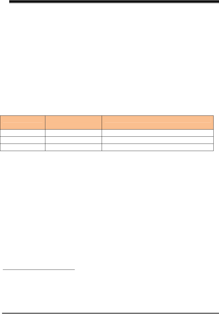
5.2. Antenna Installation
The antenna is connected by soldering the antenna pads (ANT_WGSM; ANT_D
RX) and their neighboring ground pads directly to the application’s PCB.
Figure : Antenna pads (bottom view)
The distance between the antenna pads and their neighboring GND pads has been
optimized for best possible impedance. To prevent mismatch, special attention should
be paid to these pads on the application’ PCB.
The wiring of the antenna connection, starting from the antenna pad to the
application’s antenna should result in a 50 Ω line impedance. Line width and distance
to the GND plane need to be optimized with regard to the PCB’s layer stack.
To prevent receiver desensitization due to interferences generated by fast transients like
high speed clocks on the external application PCB, it is recommended to realize the
antenna connection line using embedded Stripline rather than Micro Stripline
technology.
For type approval purposes, the use of a 50Ω coaxial antenna connector (U.FL-R-SMT)
might be necessary. In this case the U.FL-R-SMT connector should be placed as close

DLX3G User Guide 12
as possible to DLX3G‘s antenna pad.
DLX3G User Guide 13
Charpt 6. Electrical and Radio
Characteristics
6.1. Operating Temperatures
Table : Board temperature
Parameter Min Typ Max
Unit
Operating temperature range
1
Normal temperature range
Extreme temperature range
+15
-30
+25
+55
+85
°C
°C
Extended temperature range
2
-40 +95 °C
Automatic shutdown
3
Temperature measured on
DLX3G
board
<-40
---
>+95
°C
1. Operating temperature range according to 3GPP type approval specification
2. Extended operation allows normal mode data transmissions for limited time until
automatic thermal shutdown takes effect.
Within the extended temperature range (outside the operating temperature range)
there should not be any unrecoverable malfunctioning. General performance
parameters like Pout or RX sensitivity however may be reduced in their values.
The module’s life time may also be affected, if deviating from a general
temperature allocation model .
3. Due to temperature measurement uncertainty, a tolerance on the stated shutdown
thresholds may occur. The possible deviation is in the range of ± 2°C at the over
temperature and under temperature limit.
Note that within the specified operating temperature ranges the board temperature may
vary to a great extent depending on operating mode, used frequency band, radio output
power and current supply voltage. Note also the differences and dependencies that
usually exist between board (PCB) temperature and ambient temperature. The possible
ambient temperature range depends on the mechanical application design including the
module and the PCB with its size and layout. A thermal solution will have to take these
differences into account and should therefore be an integral part of application design.
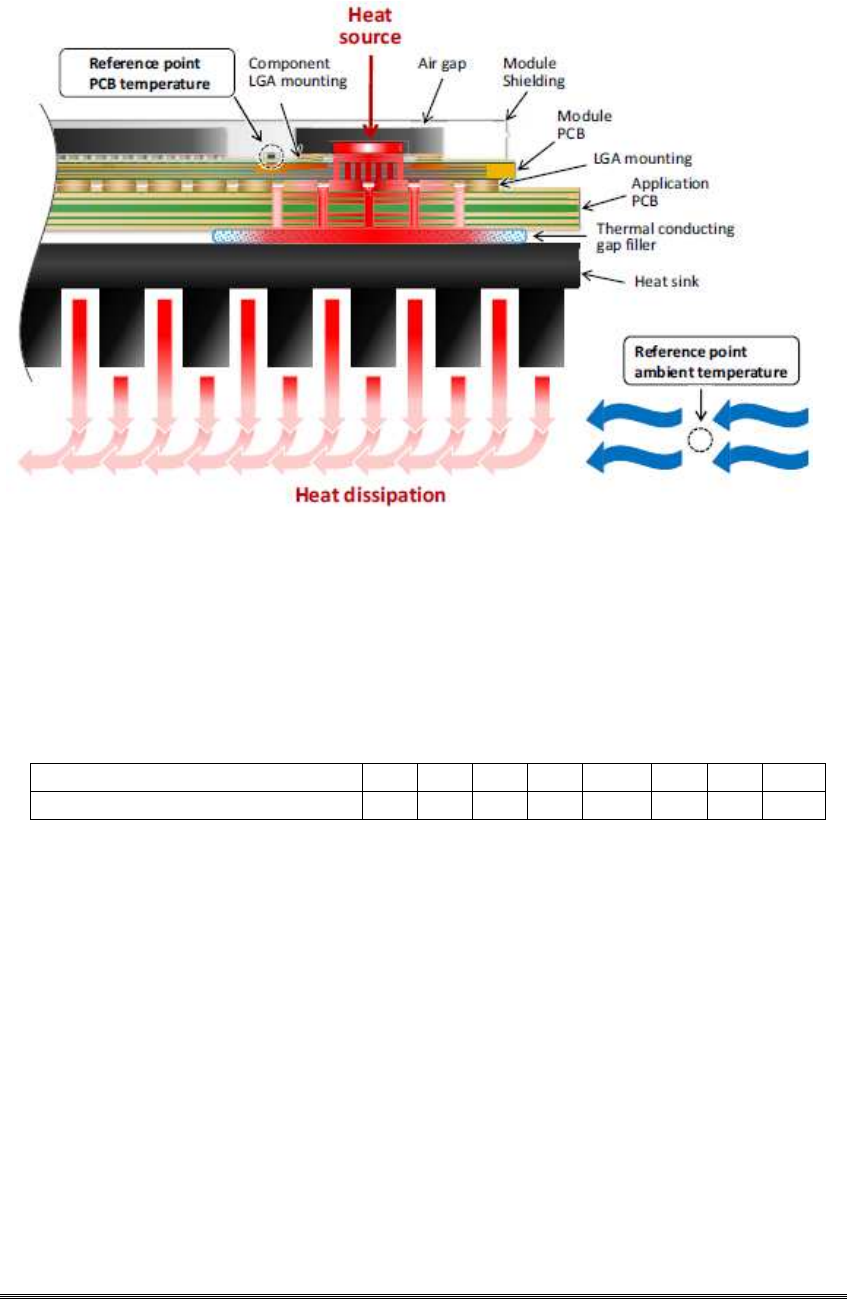
DLX3G User Guide 14
Figure: Board and ambient temperature differences
6.1.1. Temperature Allocation Model
The temperature allocation model shown in Table 21 assumes shares of a module’s
average lifetime of 10 years (given in %) during which the module is operated at
certain temperatures.
Table: Temperature allocation model
Module lifetime share (in %)
1
1 1 5 53
35 3 1 1
Module Temperature (in °C) -40
-30
-10
20
40 70
85
95
1.Based on an assumed average module lifetime of 10 years (=100%).
Any deviations from the above temperature allocation model may reduce the module’s
life span, for example if the module is operated close to the maximum automatic
shutdown temperature not only for 1% but for 20% of its product life.
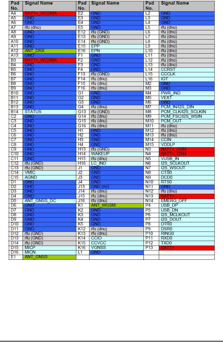
6.2. Pad Assignment and Signal Description
The SMT application interface on the DLX3G provides connecting pads to integrate
the module into external applications.
Please note that a number of connecting pads are marked as reserved for
future use (rfu) or ground (GND) and further qualified as either (dnu), (GND) or
(nc):

DLX3G User Guide 15
Pads marked "rfu" and qualified as "dnu" (do not use) may be soldered but
should not be connected to an external application.
Pads marked "rfu" and qualified as "GND" (ground) are assigned to ground
with DLX3Gmodules, but may have different assignments with future
Gemalto M2M products using thesame pad layout.
Pads marked "GND" and qualified as "nc" (not connected) are internally not
connected withDLX3G modules but may be soldered and arbitrarily be
connected to external ground.
Strongly recommends to solder all connecting pads for mechanical stability and heat
dissipation.
Table : Overview: Pad assignments
DLX3G User Guide 16
Figure : DLX3G bottom view: Pad assignments
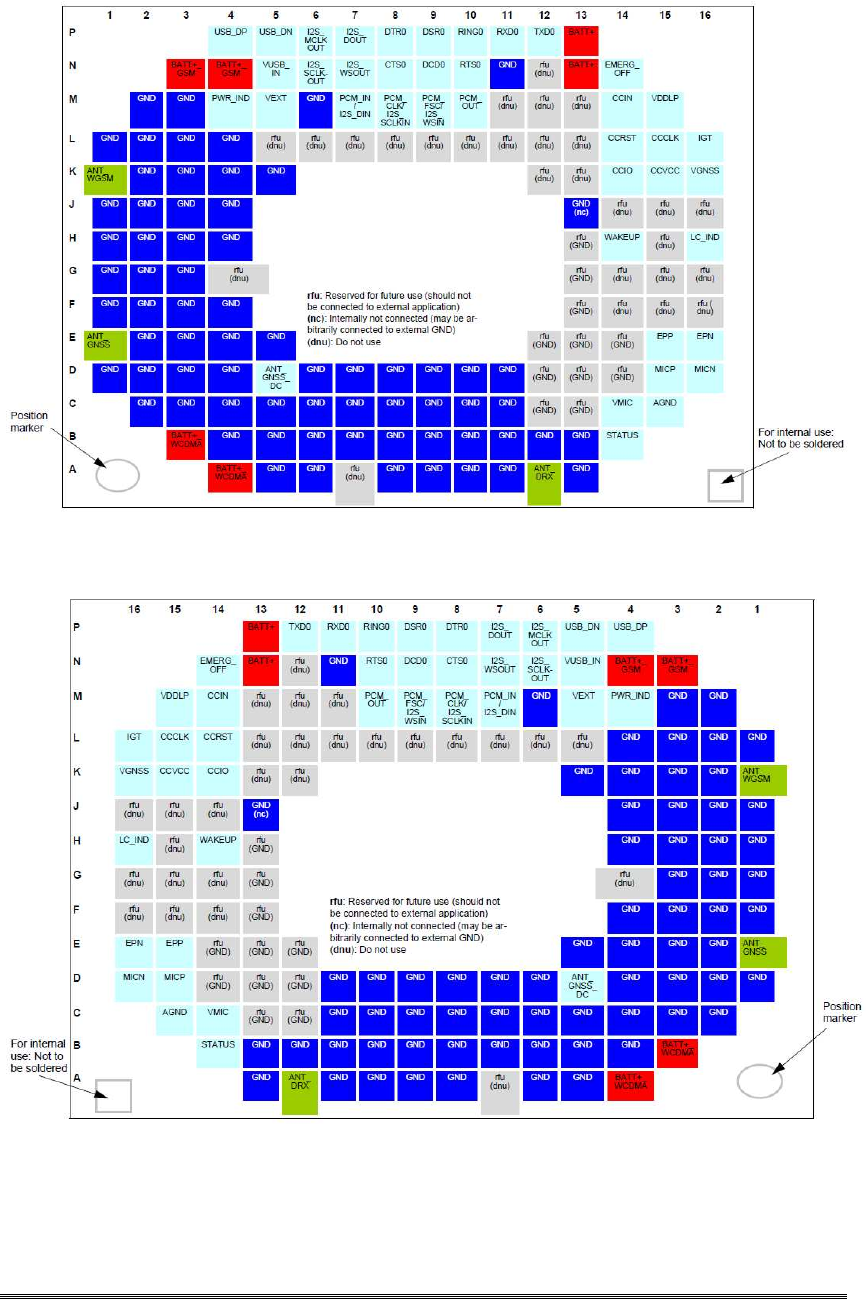
DLX3G User Guide 17
Figure : DLX3G top view: Pad assignments
DLX3G User Guide 18
6.3. RF Antenna Interface Characteristics
Table: RF Antenna interface GSM / UMTS
Parameter Conditions Min. Typical
Max.
Unit
UMTS/HSPA connectivity
1
Band I, II, V, VI, VIII
Receiver Input Sensitivity @
ARP
1
UMTS 800/850 Band VI/V
-104.7/
-110
dBm
-106.7
UMTS 900 Band VIII
-103.7
-110
dBm
UMTS 1900 Band II
-104.7
-109
dBm
UMTS 2100 Band I
-106.7
-110
dBm
RF Power @ ARP
with 50Ω
UMTS 800/850 Band VI/V
+21
+24
+25
dBm
Load
UMTS 900 Band VIII
+21
+24
+25
dBm
UMTS 1900 Band II
+21
+24
+25
dBm
UMTS 2100 Band I
+21
+24
+25
dBm
Tx noise @ ARP with max.
RF power for UMTS:
Band 1 channel 9777
Band 2 channel 9477
GNSS band
-170
dBm/Hz
GPRS coding schemes
Class 12, CS1 to CS4
EGPRS
Class 12, MCS1 to MCS9
GSM Class
Small MS
Static Receiver input Sensitivity
@ ARP
GSM 850 / E-GSM 900
-102
-109
dBm
GSM 1800 / GSM 1900
-102
-108
dBm
RF Power @ ARP
with
50Ω Load
GSM
GSM 850 / E-GSM 900
33
dBm
GSM 1800 / GSM 1900
30
dBm
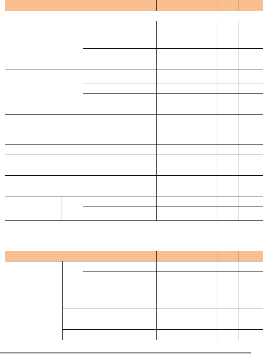
Table: RF Antenna interface GSM / UMTS
Parameter
Conditions
Min.
Typical
Max.
Unit
RF Power @ ARP with
50Ω Load, (ROPR = 4
,
i.e. no reduction)
GPRS, 1
TX
GSM 850 / E-GSM 900 33 dBm
GSM 1800 / GSM 1900 30 dBm
EDGE,
1 TX
GSM 850 / E-GSM 900 27 dBm
GSM 1800 / GSM 1900 26 dBm
GPRS, 2
TX
GSM 850 / E-GSM 900 33 dBm
GSM 1800 / GSM 1900 30 dBm
EDGE,
GSM 850 / E-GSM 900 27 dBm
DLX3G User Guide 19
2 TX GSM 1800 / GSM 1900 26 dBm
GPRS, 3
TX
GSM 850 / E-GSM 900 33 dBm
GSM 1800 / GSM 1900 30 dBm
EDGE,
3 TX
GSM 850 / E-GSM 900 27 dBm
GSM 1800 / GSM 1900 26 dBm
GPRS, 4
TX
GSM 850 / E-GSM 900 33 dBm
GSM 1800 / GSM 1900 30 dBm
EDGE,
4 TX
GSM 850 / E-GSM 900 27 dBm
GSM 1800 / GSM 1900 26 dBm
RF Power @
ARP with 50Ω
Load,
(ROPR = 5)
GPRS, 1
TX
GSM 850 / E-GSM 900 33 dBm
GSM 1800 / GSM 1900 30 dBm
EDGE,
1 TX
GSM 850 / E-GSM 900 27 dBm
GSM 1800 / GSM 1900 26 dBm
GPRS, 2
TX
GSM 850 / E-GSM 900 33 dBm
GSM 1800 / GSM 1900 30 dBm
EDGE,
2 TX
GSM 850 / E-GSM 900 27 dBm
GSM 1800 / GSM 1900 26 dBm
GPRS, 3
TX
GSM 850 / E-GSM 900 32,2 dBm
GSM 1800 / GSM 1900 29,2 dBm
EDGE,
3 TX
GSM 850 / E-GSM 900 27 dBm
GSM 1800 / GSM 1900 26 dBm
GPRS, 4
TX
GSM 850 / E-GSM 900 31 dBm
GSM 1800 / GSM 1900 28 dBm
EDGE,
4 TX
GSM 850 / E-GSM 900 27 dBm
GSM 1800 / GSM 1900 26 dBm
Parameter
Conditions
Min.
Typical
Max.
Unit
RF Power @
ARP with 50Ω
Load,
(ROPR = 6)
GPRS,
1 TX
GSM 850 / E-GSM 900
33
dBm
GSM 1800 / GSM 1900
30
dBm
EDGE,
1 TX
GSM 850 / E-GSM 900
27
dBm
GSM 1800 / GSM 1900
26
dBm
GPRS,
2 TX
GSM 850 / E-GSM 900
31
dBm
GSM 1800 / GSM 1900
28
dBm
DLX3G User Guide 20
EDGE,
2 TX
GSM 850 / E-GSM 900
27
dBm
GSM 1800 / GSM 1900
26
dBm
GPRS,
3 TX
GSM 850 / E-GSM 900
30,2
dBm
GSM 1800 / GSM 1900
27,2
dBm
EDGE,
3 TX
GSM 850 / E-GSM 900
27
dBm
GSM 1800 / GSM 1900
26
dBm
GPRS,
4 TX
GSM 850 / E-GSM 900
29
dBm
GSM 1800 / GSM 1900
26
dBm
EDGE,
4 TX
GSM 850 / E-GSM 900
27
dBm
GSM 1800 / GSM 1900
26
dBm
RF Power @
ARP with 50Ω
Load,
(ROPR = 7)
GPRS,
1 TX
GSM 850 / E-GSM 900
33
dBm
GSM 1800 / GSM 1900
30
dBm
EDGE,
1 TX
GSM 850 / E-GSM 900
27
dBm
GSM 1800 / GSM 1900
26
dBm
GPRS,
2 TX
GSM 850 / E-GSM 900
30
dBm
GSM 1800 / GSM 1900
27
dBm
EDGE,
2 TX
GSM 850 / E-GSM 900
27
dBm
GSM 1800 / GSM 1900
26
dBm
GPRS,
3 TX
GSM 850 / E-GSM 900
28,2
dBm
GSM 1800 / GSM 1900
25,2
dBm
EDGE,
3 TX
GSM 850 / E-GSM 900
27
dBm
GSM 1800 / GSM 1900
26
dBm
GPRS,
4 TX
GSM 850 / E-GSM 900
27
dBm
GSM 1800 / GSM 1900
24
dBm
EDGE,
4 TX
GSM 850 / E-GSM 900
27
dBm
GSM 1800 / GSM 1900
26
dBm
Parameter
Conditions
Min.
Typical
Max.
Unit
RF Power @
ARP with 50Ω
Load,
(ROPR = 8,
i.e. maximum
reduction)
GPRS, 1
TX
GSM 850 / E-GSM 900 33 dBm
GSM 1800 / GSM 1900 30 dBm
EDGE, 1
TX
GSM 850 / E-GSM 900 27 dBm
GSM 1800 / GSM 1900 26 dBm
DLX3G User Guide 21
GPRS, 2
TX
GSM 850 / E-GSM 900 30 dBm
GSM 1800 / GSM 1900 27 dBm
EDGE, 2
TX
GSM 850 / E-GSM 900 24 dBm
GSM 1800 / GSM 1900 23 dBm
GPRS, 3
TX
GSM 850 / E-GSM 900 28,2 dBm
GSM 1800 / GSM 1900 25,2 dBm
EDGE, 3
TX
GSM 850 / E-GSM 900 22,2 dBm
GSM 1800 / GSM 1900 21,2 dBm
GPRS, 4
TX
GSM 850 / E-GSM 900 27 dBm
GSM 1800 / GSM 1900 24 dBm
EDGE, 4
TX
GSM 850 / E-GSM 900 21 dBm
GSM 1800 / GSM 1900 20 dBm
1.Applies also to UMTS Rx diversity antenna .
6.4. GNSS Interface Characteristics
The following tables list general characteristics of the GNSS interface.
Table 33: GNSS properties
Parameter
Conditions
Min.
Typical
Max.
Unit
Frequency
GPS
1597.551
1575.42
1605.886
MHz
GLONASS
Tracking Sensitivity
Open sky
Active antenna or LNA
Passive antenna
-159
dBm
-156
Acquisition Sensitivity
Open sky
Active antenna or LNA
Passive antenna
-149
dBm
-145
Cold Start sensitivity
1
-145
dBm
Time-to-First-Fix (TTFF)
2
Cold
3
25
32
s
Warm
4
10
29
s
1. Test condition: Assumes 300 seconds timeout, QoS=1000m, and 50% yield.
2. Test condition: TTFF is defined for an open sky environment, i.e., with a clear view to the sky and a
min-imum signal level of -130dBm at the antenna for at least 3…4 satellites. This signal level
represents C/No=42dB in an NMEA $GPGSV message.
3. For test purposes a cold start may be triggered by AT command: AT^SBNW="agps",-1.
4. To optimize GPS start-up behavior, it is recommended to backup the module’s internal real time clock
via VDDLP line as described.
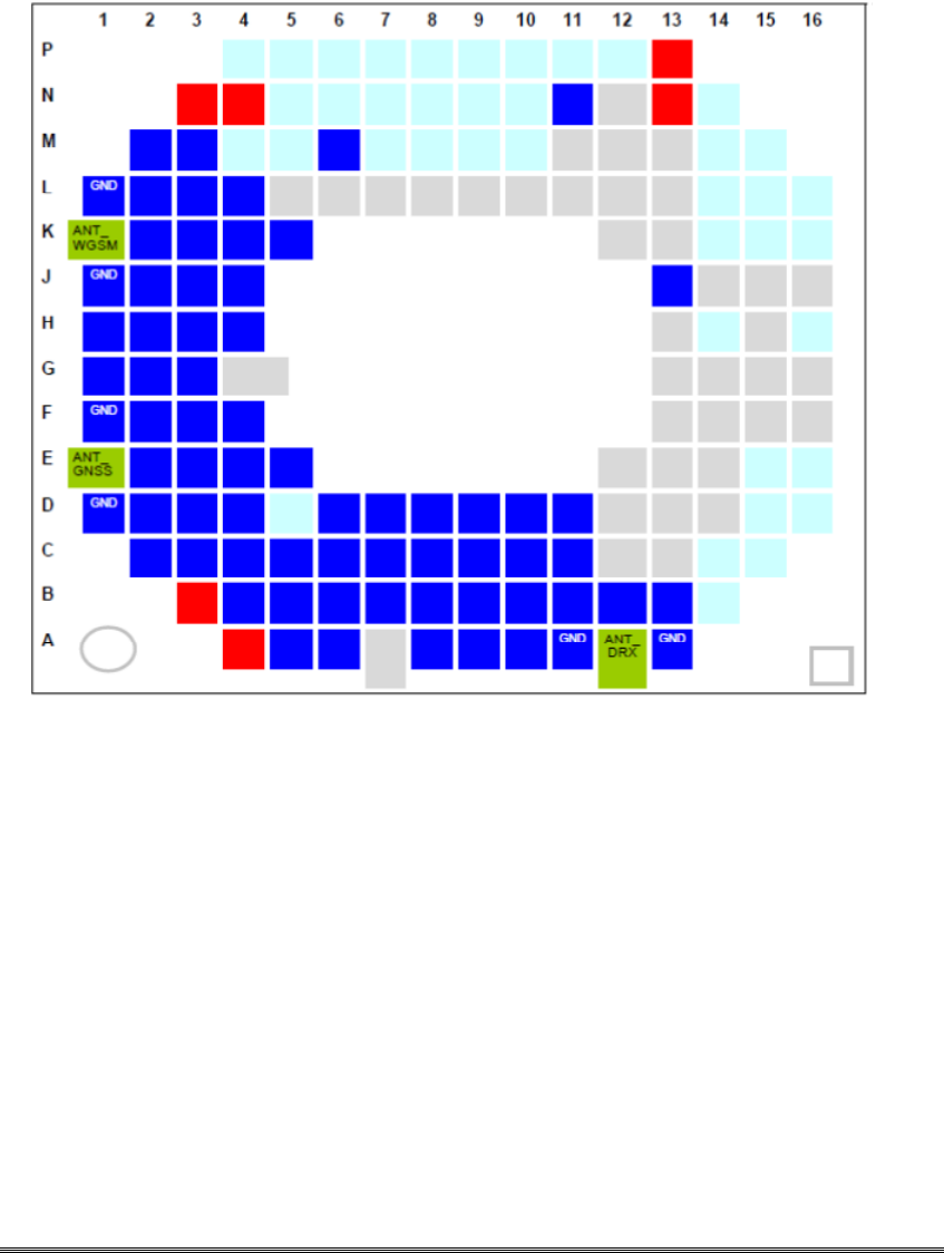
Through the external GNSS antenna DC feeding the module is able to supply an active
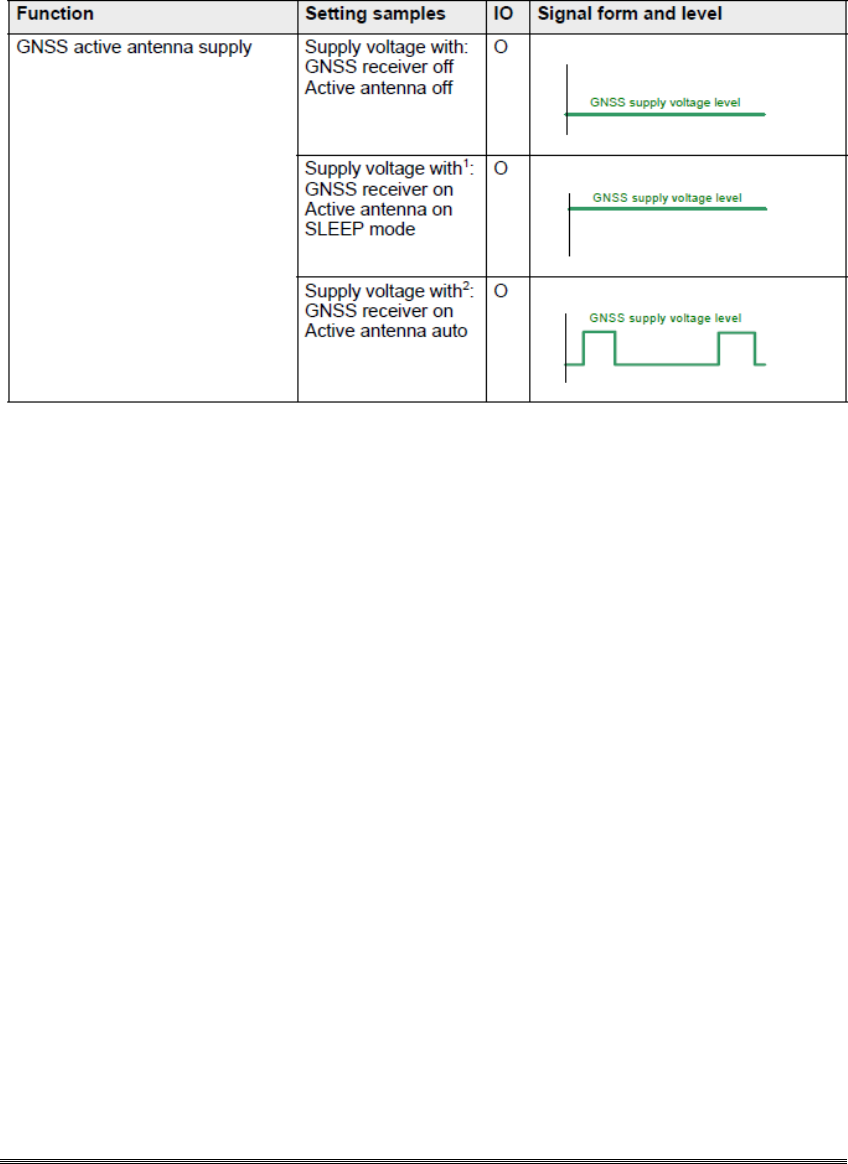
DLX3G User Guide 22
GNSS antenna. The supply voltage level at the GNSS antenna interface depends on the
GNSS con-figuration done with AT^SGPSC as shown in follow Table .
Table: Power supply for active GNSS antenna
1.
Same behavior if GNSS active antenna set to auto and AT^SGPSC="NMEA/Freq",x
with x < 4
2.
Frequency of a position request (fix) should be set with
AT^SGPSC="NMEA/Freq",x with x > 4
DLX3G User Guide 23
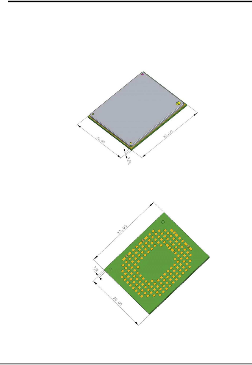
Charpt 7. Mechanics
Follow figure shows a 3D view1 of DLX3G and provides an overview of the
board's mechanical dimensions.
Length: 33mm
Width: 29mm
Height: 2mm
Top view
Bottom view
Figure: DLX3G – top and bottom view

DLX3G User Guide 24
Charpt 8. Reference Approval
8.1.
Compliance with FCC and IC Rules and Regulations
•DLX3G:
FCC Identifier: U4GDLX3G
Industry Canada Certification Number: 3862E-DLX3G
Manufacturers of mobile or fixed devices incorporating DLX3G modules are
authorized to use the FCC Grants and Industry Canada Certificates of the DLX3G
modules for their own final products according to the conditions referenced in these
documents. In this case, the FCC label of the module shall be visible from the outside,
or the host device shall bear a second label stating "Contains FCC ID: U4GDLX3G",
and accordingly “Contains IC: 3862E-DLX3G“. The integration is limited to fixed or
mobile categorized host devices, where a separation distance between the antenna and
any person of min. 20cm can be assured during normal operating conditions. For
mobile and fixed operation configurations the antenna gain, including cable loss, must
not exceed the limits 3.92dBi (850MHz) and 2.51dBi (1900MHz).
IMPORTANT:
Manufacturers of portable applications incorporating DLX3G modules are required to
have their final product certified and apply for their own FCC Grant and Industry
Canada Certificate related to the specific portable mobile. This is mandatory to meet
the SAR requirements for portable mobiles.
Changes or modifications not expressly approved by the party responsible for
compliance could void the user's authority to operate the equipment.
Note:This equipment has been tested and found to comply with the limits for a Class
B digital device, pursuant to part 15 of the FCC Rules. These limits are designed to
provide reasonable protection against harmful interference in a residential installation.
This equipment generates, uses and can radiate radio frequency energy and, if not
installed and used in accordance with the instructions, may cause harmful interference
to radio communications. However, there is no guarantee that interference will not
occur in a particular installation. If this equipment does cause harmful interference to
radio or television reception, which can be determined by turning the equipment off
and on, the user is encouraged to try to correct the interference by one or more of the
following measures:
Reorient or relocate the receiving antenna.

DLX3G User Guide 25
Increase the separation between the equipment and receiver.
Connect the equipment into an outlet on a circuit different from that to which the
receiver is connected.
Consult the dealer or an experienced radio/TV technician for help.
Industry Canada (IC) Statements:
This device complies with Industry Canada license-exempt RSS standard(s). Operation is
subject to the following two conditions: (1) this device may not cause interference, and (2)
this device must accept any interference, including interference that may cause undesired
operation of the device.
Le présent appareil est conforme aux CNR d'Industrie Canada applicables aux appareils
radio exempts de licence. L'exploitation est autorisée aux deux conditions suivantes : (1)
l'appareil ne doit pas produire de brouillage, et (2) l'utilisateur de l'appareil doit accepter
tout brouillage radioélectrique subi, même si le brouillage est susceptible d'en
compromettre le fonctionnement.
RF Radiation Exposure Statement:
This equipment complies with IC radiation exposure limits set forth for an uncontrolled
environment. This equipment should be installed and operated with a minimum distance
of 20 centimeters between the radiator and your body.
Déclaration d'exposition aux radiations:
Cet appareil est conforme aux limites d'exposition aux rayonnements définies pour un
environnement non contrôlé. Cet équipement doit être installé et utilisé à une distance
minimale de 20 centimètres entre le radiateur et votre corps.
Required end product labeling:
Any device incorporating this module must include an external, visible, permanent
marking or label which states: “Contains IC: 3862E-DLX3G”