Datalogic S r l JX2WB JOYA X2 Plus Mobile Computer User Manual III
Datalogic ADC S.r.l. JOYA X2 Plus Mobile Computer III
Contents
- 1. user manual I
- 2. user manual II
- 3. user manual III
- 4. User Manual
user manual III
DATALOGIC JOYA™ X2
70
1 3
Bluetooth communication data. If tapping on the “Close” button the
Bluetooth Manager Device window will be closed.
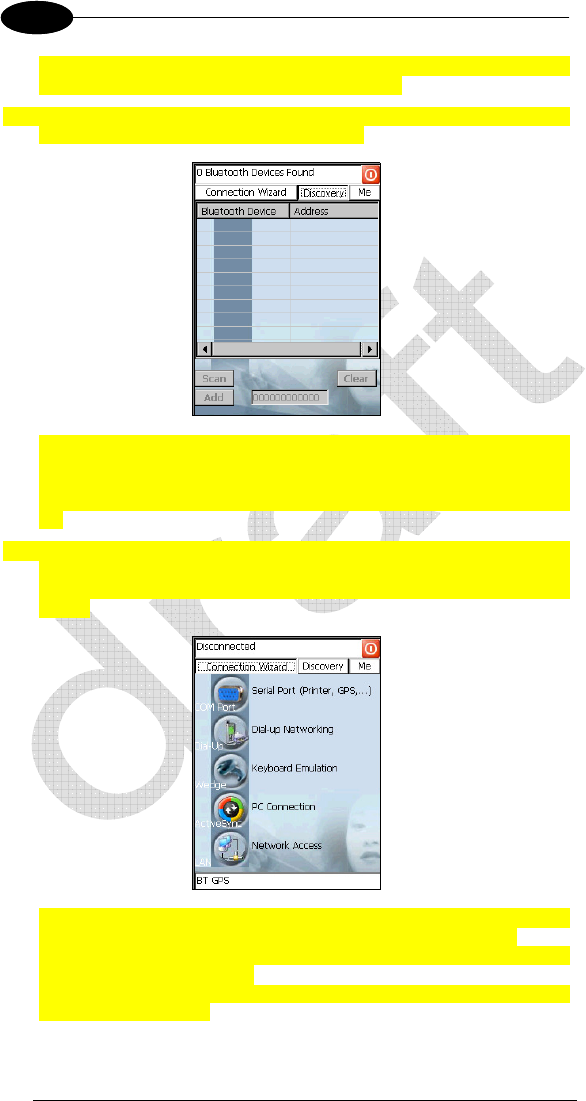
4. Tap on the “Discovery” button to enter the related window; then, tap on the
“Scan” button to run the Discovery procedure:
Once the Discovery procedure has been completed, select the desired
Bluetooth device from the list. It is also possible to digit (12 hexadecimal
digits) the Bluetooth
address of the desired device by tapping on the
“Add” button. The “Clear” button deletes all discovered devices from the
list.
5. Once the desired Bluetooth
device has been selected, tap on the
“Connection Wizard” button to enter the related window where selecting
the connection type to be used for communication with the Bluetooth
device:
The “Serial Port” button starts communication through the Bluetooth
serial port COM 5 (typically used for connection with GPS devices).
The “Printer” button starts communication with a printer through the
Bluetooth serial port COM 5.
The “Kbd Emulation” button allows connection with a barcode reader using
the keyboard emulation.

USE AND FUNCTIONING
71
3
The “ActiveSync” button starts communication with a PC equipped with a
Bluetooth antenna and the related ActiveSync.
6. Hide the Bluetooth Manager Device window by tapping on the icon
available on each window or close it through the “Close” button available
in the “Me” window (see step 3 of this procedure).

DATALOGIC JOYA™ X2
72
1 3
3.14.5 FTP Server Setup
The Datalogic JOYA™ X2 Operating System includes a File Transfer Protocol
(FTP) server. FTP is used for copying files to and from remote computer
systems over a network using TCP/IP. You can establish a connection to your
Datalogic JOYA™ X2 using its FTP Server through the WLAN using the WiFi
radio
Proceed as follows:
1. Create a registry file (extension .reg) to setup and enable FTP Server
communication. A simple example file for “anonymous” logon is given
below:
REGEDIT4
[HKEY_LOCAL_MACHINE\Comm\FTPD]
"DefaultDir"="\\"
"AllowAnonymousUpload"=dword:00000001
"UseAuthentication"=dword:00000000
"BaseDir"="\\"
"IsEnabled"=dword:00000001
"LogSize"=dword:00001000
"DebugOutputMask"=dword:00000017
"DebugOutputChannels"=dword:00000002
"IdleTimeout"=dword:0000012c
"AllowAnonymous"=dword:00000001
"AllowAnonymousVroots"=dword:00000001
2. Copy this file to the Datalogic JOYA™ X2 using ActiveSync
®
.
3. Launch the .reg file from the Datalogic JOYA™ X2
4. Perform a warm boot on the Datalogic JOYA™ X2
5. From the PC > Explorer address bar (or running an FTP Client from the
PC), enter the Datalogic JOYA™ X2 IP address.
For more information on FTP Client/Server connections refer
to the following web page:
http://msdn2.microsoft.com/en-us/library/aa922316.aspx.
NOTE

USE AND FUNCTIONING
73
3
3.15 BACKUP DIRECTORY FILE MANAGEMENT
All of the Windows CE 6.0 system files reside in RAM (volatile memory) except
for the Backup directory, which resides in FLASH (non-volatile memory).
Therefore the contents of the Backup directory are persistent even if the mobile
computer is rebooted or the battery pack is changed. You can save your more
important files that you don't want to lose due to mobile computer reboot, in the
Backup directory or create a sub-directory within Backup. Even though the
Windows Directory resides in RAM, it often contains files or sub-directories
created by the user or by installation programs that you don't want to lose at re-
boot. To keep these files persistent it is necessary to copy them to the directory
\Backup\Windows. This directory doesn't exist originally (only Backup exists),
and therefore it must be created. At the next cold boot, before activating the
shell, Windows CE 6.0 will copy the contents including all sub-directories of
\Backup\Windows to \Windows. Likewise, to maintain files that must be run at
Windows CE 6.0 startup, (i.e. .exe, .lnk, .vb, .htm, etc.), it is necessary to copy
them to the directory \Backup\Startup. This directory does not exist originally
(only Backup exists), and therefore it must be created. The applications
programs will be run after any type of re-boot (both software and cold boot).
However, since file system persistence is performed after the
“\BACKUP\Startup” folder execution, for those programs which depends upon
the DLLs and resources copied from “\BACKUP\Windows” to “\Windows”
during the cold-boot, the “\BACKUP\Windows\dl_startup” folder is to be
preferred to execute programs and applications, since the execution follows the
file system restore (and no DLL and resource dependence failure will occur). As
an alternative to the Safe Setup function, it is possible to copy the .cab files to
the directory \Backup\Cabfiles (the Cabfiles sub-directory doesn't exists
originally and must therefore be created) and perform a mobile computer cold
boot to have the application installed. Once these files are copied to the
directory \Backup\Cabfiles, the application will be run after each re-boot. From
the second cold boot on, a message may be displayed such as "<application
name> is already installed. Reinstall?". This message blocks the boot process.
Press the [Enter] key to continue the system initialization. In a specific JOYA™
X2 version, a 4GB DS type card is available as permanent general purposes
storage device (path = \Storage Card).

DATALOGIC JOYA™ X2
74
1 3
USE AND FUNCTIONING
75
3
3.16 FIRMWARE UPDATE
The Datalogic JOYA™ X2 is equipped with a tool that implements a firmware
update service.
This tool, called Datalogic Updater (DLUpdater), is compatible with all
hardware versions of the Datalogic WindowsCE 6.0 models:
An update can be explicitly invoked by running the application DLUpdater.exe,
provided together with the update file DLUpdate.zip. The update must be
contained in the root.
It is advisable, even if not binding, to connect the terminal to
an external power source before starting the update
process. This prevents the terminal from turning off while
running and avoids a corruption of flash content.
CAUTION
After the update process, all the data stored in the backup
folder could be irreparably lost, as well as the device
configuration (even that one stored in persistent memory).
Therefore, before starting a firmware update it is advisable
to run a backup copy of the data you want to preserve on
PC (e.g. using ActiveSync or Windows Mobile Device
Center Connection).
CAUTION
3.16.1 Retrieving a Firmware Image Update
The following instructions use Internet Explorer to retrieve the most current
firmware image.
1. Launch Internet Explorer on your PC and navigate to
http://www.adc.datalogic.com..
2. Navigate the Downloads section of the web site.
3. Select the product, desired language, and software updates. Click Go!
4. Select the file you want to download, then click Save and navigate to the
location where you want to save the firmware files.
5. Click Save again to begin copying the files to your local machine (or local
network location).
DATALOGIC JOYA™ X2
76
1 3
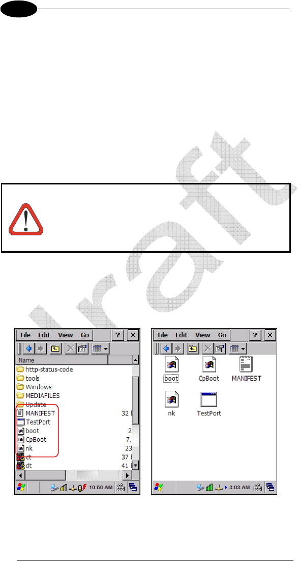
3.16.2 Firmware Update Procedure
1. Download the update from the web site (see previous par.). It is a zip file
containing the files:
• DLUpdater.exe – that starts the update;
• DLUpdate.zip – archive file containing the updated firmware;
2. Copy the files DLUpdater.exe and DLUpdate.zip in the root.
3. Open the root on the terminal and run DLUpdater.exe by double tap the
icon (JOYA™ X2 Plus) or by ActiveSync/Mobile Companion (JOYA™ X2
Basic).
4. The DLUpdater starts decompressing files in the memory card or in the
\Backup folder depending upon the JOYA™ X2 version.
There are no feedback messages on the screen while the
DLUpdater operates, just wait for the terminal to reboot.
CAUTION
5. DLUpdater performs all the necessary operations of check, update and
verify and, if no errors occur during the update, terminates the running
invoking a cold boot of the terminal, so that the update process could be
completed
6. At the end of the process, the updated files will remain where
decompressed. They must be manually removed.

USE AND FUNCTIONING
77
3
3.17 DAATALOGIC CONFIGURATION UTILITY
Datalogic Configuration Utility (DCU) is a Datalogic Windows-based utility tool
allowing the uploading, modifying and downloading of the configuration of a
Datalogic device. Configuration settings include Scanner, Control Panel, and
Datalogic Desktop Utility (DDU). The DCU installer is downloadable from the
Datalogic website (http://www.datalogic.com/eng/support-services/automatic-
data-capture/downloads/software-utilities-sw-2.html).
DCU functions in both direct (with an ActiveSync connection) and indirect (with
Wavelink Avalanche™) modes.
In direct mode, connect a device through ActiveSync and then click on the Get
from Device icon to receive the device’s current configuration.
Once loaded, the Configuration Tree (on the left side of the window) is used to
navigate the device’s configuration. The right side of the window is a work area
where the values of different parameters may be set for each branch of the
configuration tree. Click on the parameter group branch to open it and inspect
the parameters you wish to modify.
After altering the device’s configuration, the new configuration can be sent to
the terminal by clicking on the Send to Device icon.
Reference the Wavelink Avalanche™ documentation on the Wavelink website
(www.wavelink.com/Datalogic-device-downloads) for a description of indirect
mode for DCU, which will allow you to update the configuration of multiple
devices simultaneously over Wi-Fi.
3.18 DATALOGIC DESKTOP UTILITY
Datalogic Desktop Utility (DDU) allows administrators to configure Windows®
CE and Embedded Handheld devices to control individual user access. This
includes the ability to:
• Prevent users from changing your device OS settings.
• Use Application Selector to replace desktop with a selection of
authorized applications
• Internet Explorer access restriction, configuration and customized
recovery mechanisms.
To open DDU for the first time, tap Start > Settings > Control Panel > or Start >
programs > Device tools > and then double tap the icon for “Datalogic Desktop
Uility”.
DATALOGIC JOYA™ X2
78
1 4
4 MAINTENANCE
Battery packs are not initially charged. Therefore the initial
operation to perform is to charge them. See below.
NOTE
By default, the battery pack is disconnected at the factory
to avoid damage due to excessive draining.
Annual replacement of rechargeable battery pack avoids
possible risks or abnormalities and ensures maximum
performance.
CAUTION
4.1 CHARGING THE BATTERY PACK
The battery pack autonomy varies according to factors, such as the frequency
of barcode scanning, RF usage, etc.
The battery icon on the Taskbar indicates when the battery pack is low.
It is also possible to recharge the battery pack by using a JOYA Cradle.
Moreover recharging is possible by USB Direct connection with the host
computer, but with longer charging times and in this case it is advised to keep
the mobile computer off.
The battery pack autonomy varies according to many factors,
such as the frequency of barcode scanning, RF usage, battery
life, storage, environmental conditions, etc.
NOTE
The maximum time required to recharge a completely run-
down standard battery pack is about 12 hours by using the
USB and 7 hours by using the cradle.
CAUTION
MAINTENANCE
79
4
Even if the storage temperature range is wider, In order to
achieve the longest battery life, store the terminal and the
spare batteries between 20 to 30 ºC (68 to 86 ºF).
JOYA™ X2 should be charged at an ambient temperature
between 0 - 35º C to achieve the maximum charging rate.
Never charge the main device or spare batteries in a closed
space where excessive heat can build up.
NOTE
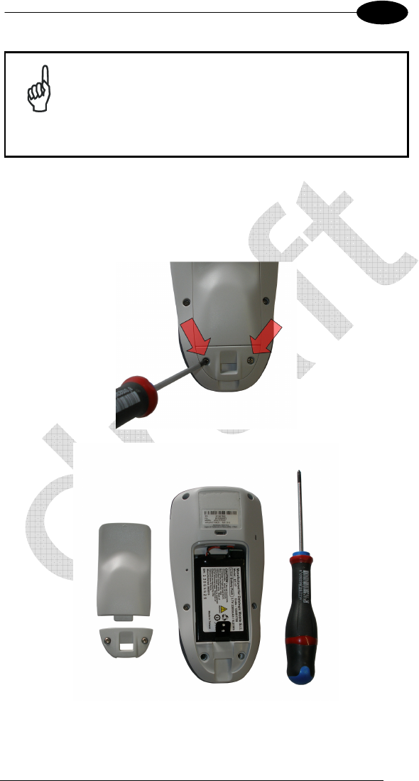
4.2 REPLACING THE BATTERY PACK
To correctly replace the battery pack, proceed as follows.
1. Unscrew the two screws placed on the back bottom. The battery pack
cover is now released.

DATALOGIC JOYA™ X2
80
1 4
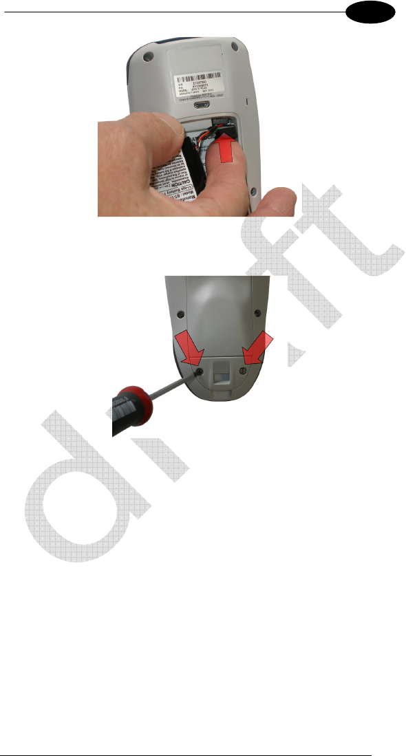
2. Remove the cover and then the battery pack, using the proper plastic
strips. Pay attention when disconnecting the connector.
3. Install the new battery pack, first insert the connector respecting the right
way, then the upper side, finally the bottom side, leaving the plastic strip
available for future replace.
MAINTENANCE
81
4
4. For correct locking, first insert the upper part of the battery cover, then the
lower and screw the two screws placed on the back bottom.

DATALOGIC JOYA™ X2
82
1 4
WARNING
To install, charge and/or do any other action on the battery,
follow this manual.
The battery pack may get hot, explode, ignite, and/or cause
serious injury if exposed to abusive conditions.
If the battery pack is replaced with an improper type, there is risk
of explosion.
Do not place the battery pack in or near a fire or heat; do not
place the battery pack in direct sunlight, or use or store the
battery pack inside unventilated areas in hot weather; do not
place the battery pack in microwave ovens, dryer, high pressure
containers, on induction cookware or similar device. Doing so
may cause the battery pack to generate heat, explode or ignite.
Using the battery pack in this manner may also result in a loss of
performance and a shortened life expectancy.
Use only a Datalogic ADC approved power supply. The use of
an alternative power supply will void the product warranty, may
cause product damage and may cause heat, explode or ignite.
The area in which the units are charged should be clear of
debris and combustible materials or chemicals.
Do not use the battery pack of this terminal for power devices
different from this mobile computer.
Immediately discontinue use of the battery pack if, while using,
charging or storing the battery pack, the battery pack emits an
unusual smell, feels hot, changes colour or shape, or appears
abnormal in any other way.
Do not short-circuit the battery pack contacts connecting the
positive terminal and negative terminal. This might happen, for
example, when you carry a spare battery pack in your pocket or
purse; accidental short–circuiting can occur when a metallic
object such as a coin, clip, or pen causes direct connection of
the contacts of the battery pack (these look like metal strips on
the battery pack). Short–circuiting the terminals may damage the
battery pack or the connecting object.
Do not apply voltages to the battery pack contacts.
Do not pierce the battery pack with nails, strike it with a hammer,
step on it or otherwise subject it to strong impacts or shocks.
Do not disassemble or modify (i.e. bend, crush or deform) the
battery pack. The battery pack contains safety and protection
devices, which, if damaged, may cause the battery pack to
generate heat, explode or ignite.
MAINTENANCE
83
4
WARNING
In case of leakage of liquid from the battery, avoid contact with
liquid the skin or eyes. If the contact occurs, immediately wash
the affected area with water and consult a doctor.
Do not solder directly onto the battery pack.
Do not expose the battery pack to liquids.
Avoid any knocks or excessive vibrations. If the device or the
battery is dropped, especially on a hard surface, you should take
it to the nearest Authorised Repair Centre for inspection before
continuing to use it.
Do not replace the battery pack when the device is turned on.
Do not remove or damage the battery pack’s label.
Do not use the battery pack if it is damaged in any part.
Battery pack usage by children should be supervised.
Collect and recycle waste batteries separately from the device in
comply with European Directive 2006/66/EC, 2011/65/EC,
2012/19/EC and subsequent modifications, US and China
regulatory and others laws and regulations about environment.
In order to guarantee an adequate operating autonomy,
when replacing the battery pack the mobile computer
checks the battery energy level. If the battery is not
sufficiently charged, Datalogic JOYA™ X2 does not turn
on. In this case, either substitute the battery pack with a
charged one (sufficiently charged) or insert Datalogic
JOYA™ X2 into a powered cradle or plug into the USB PC
port.
NOTE
To achieve the best battery life, turn off the radios not in
use.
NOTE
4.3 CLEANING THE MOBILE COMPUTER
Periodically clean the Datalogic JOYA™ X2 with a slightly dampened cloth.
DATALOGIC JOYA™ X2
84
1 5
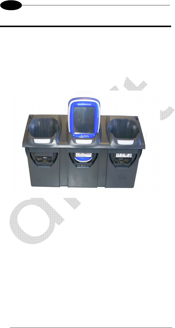
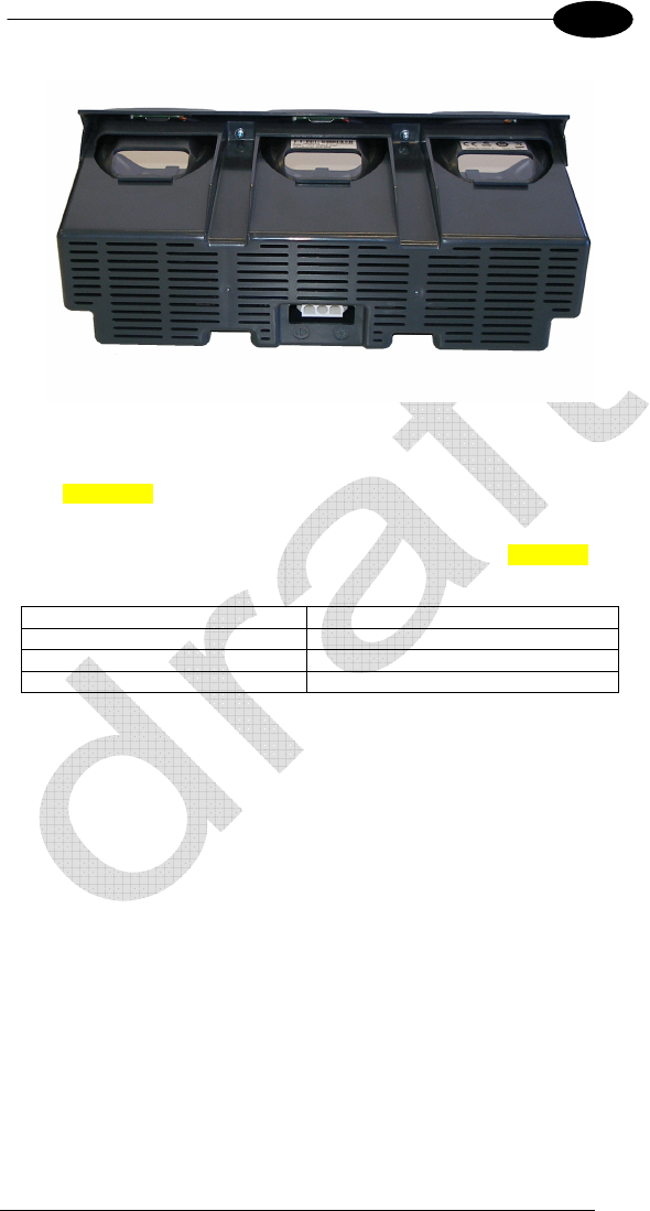
5 JOYA CRADLE DISPENSER
5.1 INTRODUCTION
JOYA Cradle Dispenser has the following responsibilities:
• to recognize the insertion and extraction of the JOYA™ X2
• to control the blocking device
• to signal status using the LEDs
• to supply power to the JOYA™ X2 for battery recharging
JOYA Cradle Dispenser has three JOYA™ X2 slots, each equipped with its
own control unit, an electromechanical system for blocking/releasing the
terminal, notification light, battery power and recharging circuits.
Its special structure makes it possible to design any type of dispenser (wall-
mounted or island) easily, allowing twice the number of terminals to be installed
per vertical square meter with respect to the competing systems.
5.2 ACCESSORIES
• 91ACC1000 Power Supply 12V 300W
• 91ACC0730 Power Junction Cable I90x/3 Cradle (8 pcs.)
• 91ACC0650 Term. Unlock Magnets (5 pcs.)
JOYA CRADLE DISPENSER
85
5
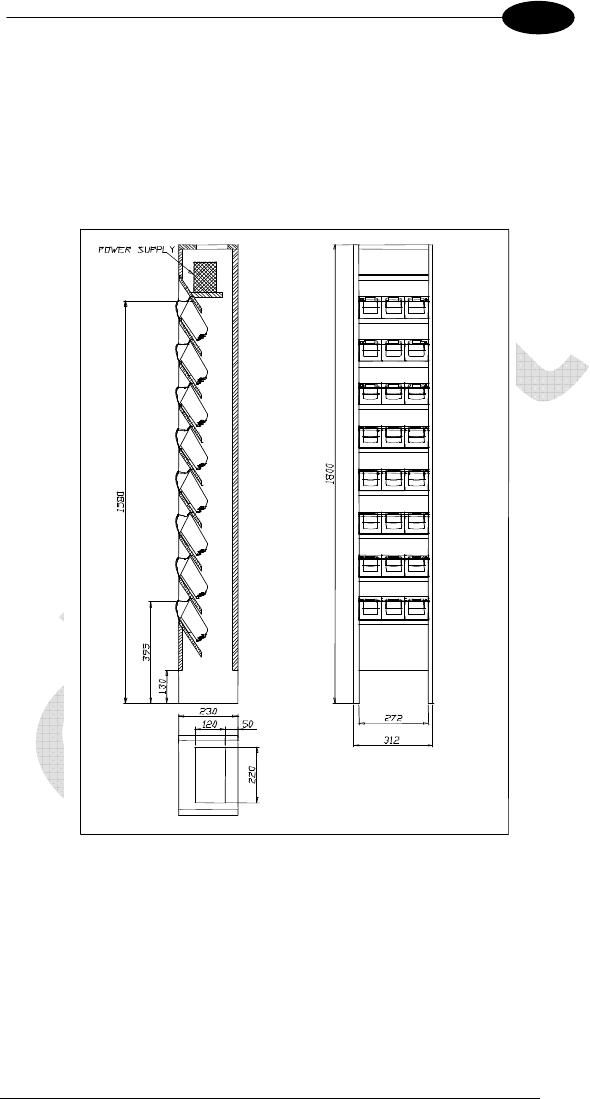
5.3 INSTALLATION REQUIREMENTS
The figure below represents an 8 JOYA™ X2 Cradle Dispenser Base Unit
organized in a single column.
JOYA™ X2 will be inserted into the JOYA Cradle Dispensers are at a minimum
height of approximately 40 cm. from the floor and a maximum height of about
160 cm. from the floor.
DATALOGIC JOYA™ X2
86
1 5
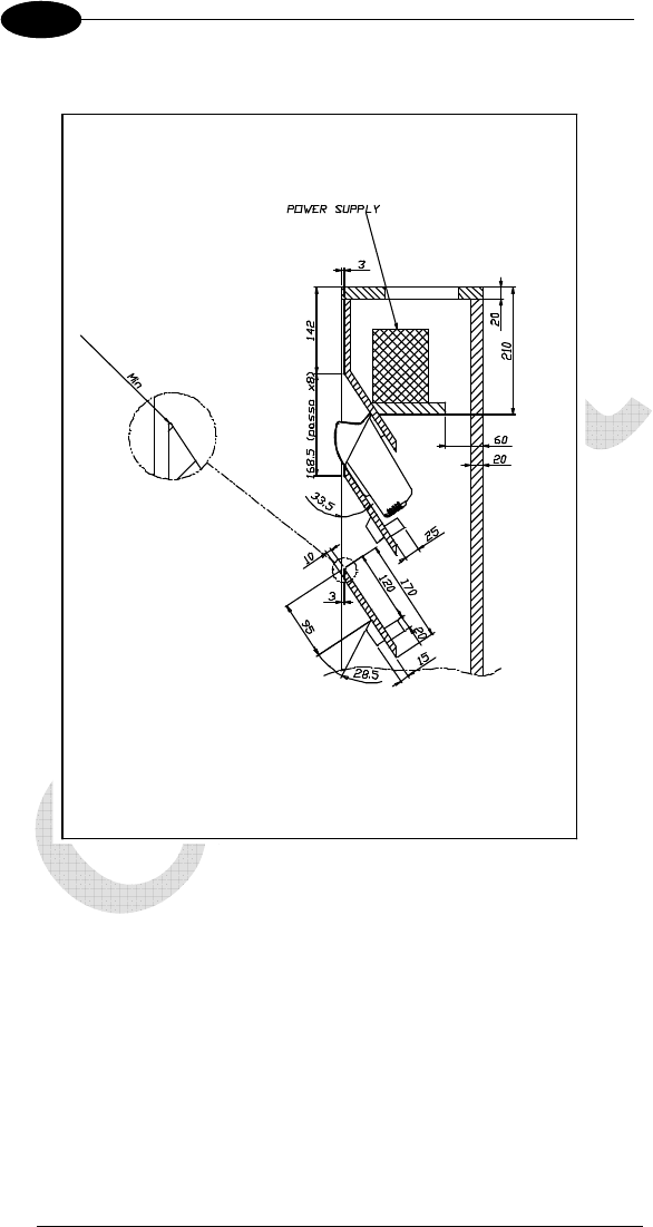
5.3.1 Base Unit Construction Details
All of the dimensional quotes necessary for building and correctly mounting the
supporting crosspieces and fixing blocks for the JOYA Cradle Dispensers are
indicated.
The zoom of the upper edge of the supporting crosspiece indicates the
necessity of reducing the radius of this edge as much as possible in order to
provide a stable contact surface for the upper cover of the JOYA Cradle
Dispenser.
The power supply shelf is positioned so that it guarantees a sufficient volume of
air flow for the cooling of the power supplies.
JOYA CRADLE DISPENSER
87
5
Suggestion:
The cradle fixing blocks shown in the figures are mounted to the supporting
crosspieces under the JOYA Cradle Dispensers. Their purpose is to prevent
the Cradle Dispensers from falling inside the cabinet during the mounting
phase in which the JOYA Cradle Dispensers may not be correctly positioned
before fixing them.
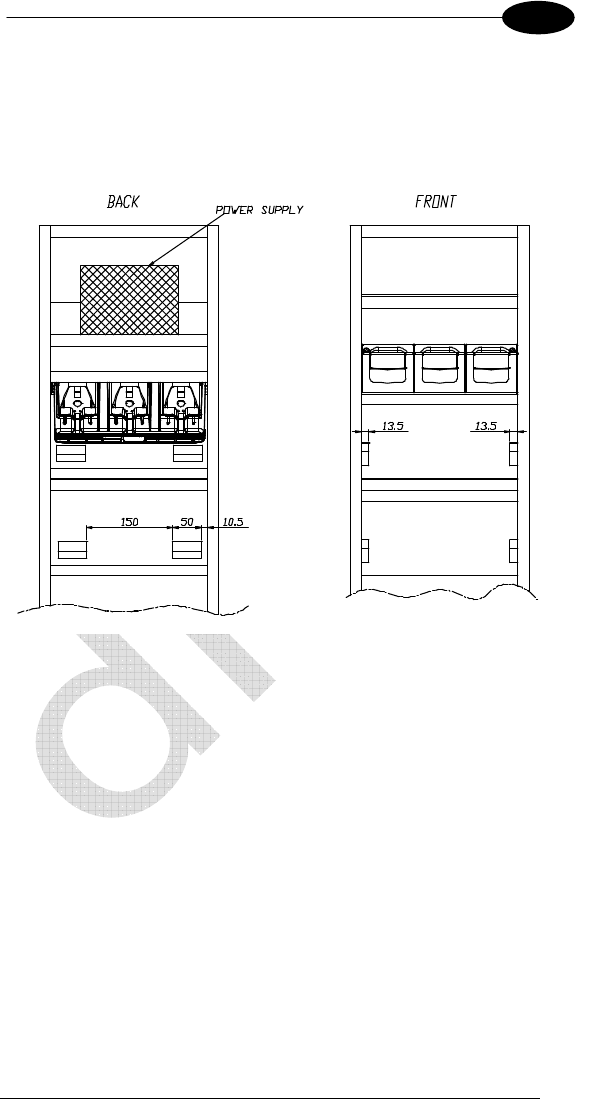
5.3.2 JOYA Cradle Dispenser Supports
JOYA Cradle Dispensers are supported inside the Base Unit from crosspieces
fixed to the side panels of the cabinet. The front part of each JOYA Cradle
Dispenser cover rests on the upper edge of its supporting crosspiece, while the
back part rests on two fixing blocks attached to the crosspiece above it.
JOYA Cradle Dispenser is mounted to the cabinet using two screws that are
inserted into the holes provided towards the back of its cover and screwed into
the corresponding holes in the fixing blocks.
To correctly position JOYA Cradle Dispensers, the supporting crosspieces and
the fixing blocks must be mounted according to the dimensional quotes and the
angles.

DATALOGIC JOYA™ X2
88
1 5
5.3.3 Internal Cabinet Space and Openings
The space between the rear of the JOYA Cradle Dispensers and the back part
of the cabinet must be left for two reasons:
• it must be possible to retrieve objects that accidentally fall through the
cradles from the floor behind the cabinet.
• there must be a zone for air to freely circulate behind the JOYA Cradle
Dispensers to aid their cooling during operation.
For these reasons the cabinet must not be closed at the bottom and must have
an opening at the top. To allow retrieval of objects that could accidentally fall
into the cabinet, it is necessary to leave space between the lower edge of the
lowest crosspiece and the floor. This space must be a compromise between
the necessity of allowing object retrieval and the necessity of prohibiting access
behind the cabinet.
5.3.4 Anchoring and Maintenance Issues
The cabinet must be anchored to the wall in at least two points, since the
contact surface area on the floor is small and therefore not sufficient to
guarantee full stability.
Suggestion:
It is preferable for the cabinet to have a removable back panel for easy access
inside when performing cabling.
The top of the cabinet should also be removable for access to the power
supplies during maintenance without the necessity of removing the cabinet
from the anchoring points to the wall. For this reason the power supplies should
also be able to be mounted and removed from the top of the cabinet.
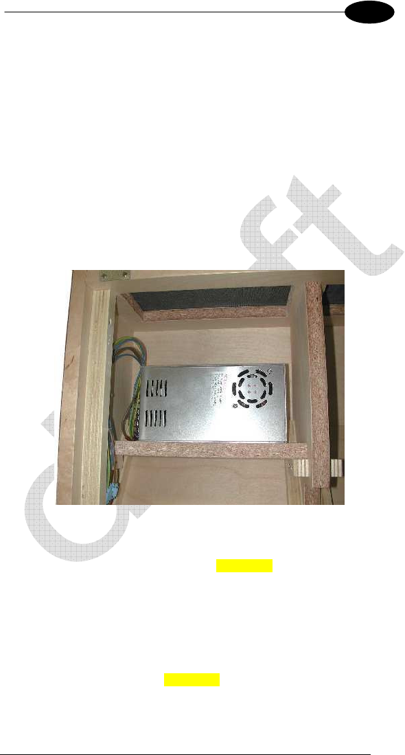
5.3.5 Power Supply Positioning and Cooling
At the top of the cabinet there must be an opening not small. This opening
generates a natural convection effect allowing the flow of air to remove heat
generated by the JOYA Cradle Dispensers during their operation.
The power supplies or single power supply must be mounted on their shelf in
the upper part of the cabinet.
This position for the power supplies has been chosen to aid the flow of air
inside the cabinet taking advantage of natural convection. The hot air
generated by the power supplies, in fact, leaves through the opening at the top
and takes in cooler air from the lower part of the cabinet.
The power supplies therefore must be placed on the shelf in such a way as not
to block the flow of air coming up from the lower part of the cabinet.
JOYA CRADLE DISPENSER
89
5
The opening at the top of the cabinet must be covered with a grill or mesh,
which allows air to flow freely but protects against access to the inside of the
cabinet. In this way the power supplies can not be reached externally.
Power Supplies
• Single 300 W power supply capable of supplying all 8 Cradle Dispensers
(91ACC1000 Power Supply 12V 300W).
The power supplies must be mounted inside the cabinet onto their shelves so
that the necessary air flow for cooling the JOYA Cradle Dispensers below is not
limited. In addition, the openings on the power supplies must not be obstructed
at any time, which could impede correct cooling.
If the power supplies are mounted using angular brackets, use the threaded
holes provided on the power supply case. Make sure that the mounting screws
are size M4 and do not penetrate the power supply case by more than 5.5 mm.
5.3.6 AC Power Cabling
Connection of the Power Supply to the AC line must be made using a cable
having characteristics that meet the Safety Normatives currently in force.
The cable must have an earth ground wire that is connected to the earth
ground terminal of the power supply.
The cable must have wire dimensions that meet or exceed the nominal current
and power specifications of the power supply to which it is connected.
There must be a cable clamp applied to the power cable where it enters the
cabinet, which meets the Safety Normatives currently in force.
DATALOGIC JOYA™ X2
90
1 5
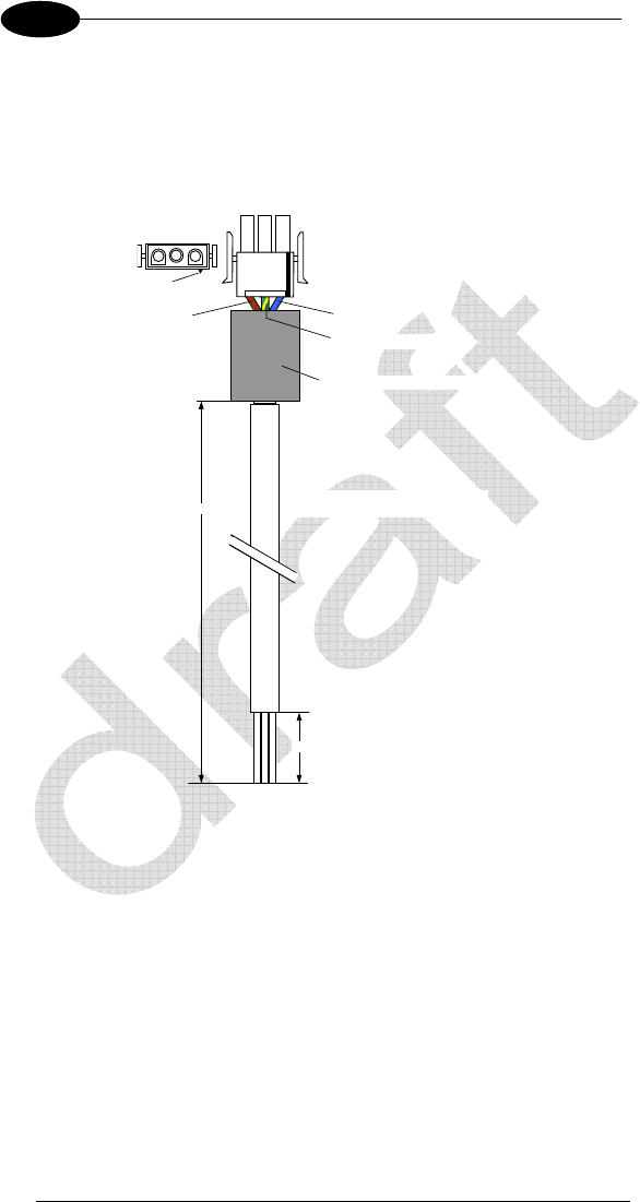
5.3.7 Wiring
To wire the JOYA Cradle Dispensers, pre-wired power junction cables are
provided as accessories (91ACC0730 Power Junction Cable I90x/3 Cradle -8
pcs.), which are ready to be connected to the power connector at the bottom of
the JOYA Cradle Dispenser.
3 2 1
BLUE
Connector: AMP 1-480700-0
Contacts: AMP 350536-1
Series: UNIVERSAL MATE-N-LOCK
Ferrite: RICHCO RRH120-056-300
Cable: flexible flameproof 3-wire stranded
individual wire diameter = 1 mm²
300 mm
40 mm
BROWN
YELLOW
-GREEN
3 2 1
Key
To connect the JOYA Cradle Dispensers to the power supplies, the pre-wired
junction cables must be connected to three multi-strand copper wires (singly or
incorporated in a cable) and these must be connected to the power supply
terminals.
JOYA CRADLE DISPENSER
91
5
These wiring connections must be made with particular care and meet or
exceed the nominal current and power specifications; the current flowing
through them is 2.5 A per JOYA Cradle Dispenser. The wires must meet the
Safety Normatives currently in force.
The following table indicates the maximum current specifications for some wire
conductor sections according to the EN 60950 Electrical Safety Normative.
Maximum Current Wire Section
10 A 1 mm²
16 A 1.5 mm²
25 A 2.5 mm²
Suggestion:
It is advised to use a cable made up of two groups of three-conductor multi-
stranded wire with flame retardant insulation (single or together in a cable with
flame retardant insulation) having a copper wire section equal to 1.5 mm².
The two groups of three conductors are connected to the output terminals of
the power supplies: in the case of two power supplies, one group of wires is
connected to one power supply and the other group is connected to the other
power supply; in the case of a single power supply, both groups of wires are
connected to the same power supply.
Each three conductor cable group must be used to connect four of the JOYA
Cradle Dispensers mounted in the Base Unit via their junction cables.
JOYA Cradle Dispenser junction cables can be connected to the three-
conductor cable groups using IDC connectors having a maximum current
capability not less than 3 A.
DATALOGIC JOYA™ X2
92
1 5
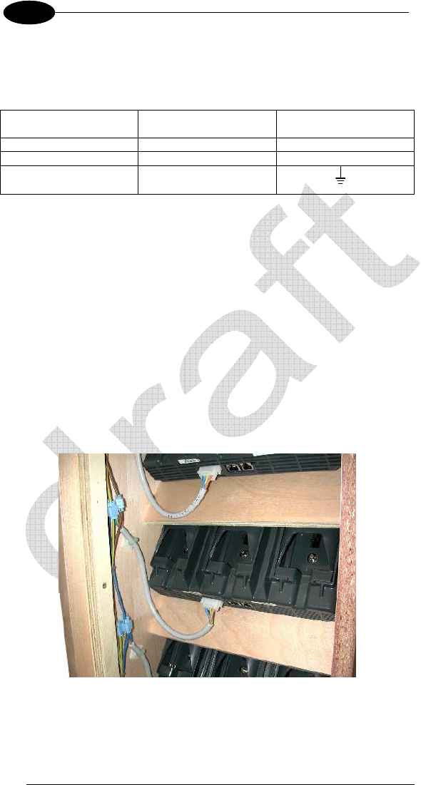
5.3.8 Cable to Power Supply Connection
All 12 Vdc power supply connections, both the main power cable and the power
junction cables must be made according to the following requirements:
Power Junction Cable
Wires Connection Designation
Brown +12V +V
Blue ground -V
Yellow-Green earth ground FG or
5.3.9 Affixing Cables to Cabinet
The ends of the junction cables that are connected to the main cable groups
must be affixed to the cabinet sides so as to guarantee the following conditions:
• it must be possible to extract the JOYA Cradle Dispenser from the front
of the cabinet while the cable is connected so that the connector can be
plugged in or out of the Cradle Dispenser from outside the cabinet.
• when the JOYA Cradle Dispenser is mounted in the cabinet, its cable
must be laid against the supporting crosspiece so that it does not block
objects which may accidentally fall through the Cradle Dispenser into the
inside of the cabinet.
Next image shows an example of affixing the Cradle Dispenser cables to the
cabinet. The Cradle Dispenser cables are connected to the main power cables
through IDC connectors.
5.3.10 Safety Precautions

JOYA CRADLE DISPENSER
93
5
JOYA Cradle Dispenser Cabinet, the relative electrical wiring and connection to
the AC power line must be made according to the Safety Normative currently in
force.
The following paragraphs contain some particularly important considerations to
keep in mind.
• Cradle Dispenser Operating Temperature
JOYA Cradle Dispensers are designed and built to operate within the
following environmental conditions:
Operating Temperature Range: 10 to 30 °C
Storage Temperature Range: -20 to 60 °C
Humidity: 90% non condensing
• Cabinet
The cabinet must not have any exposed sharp edges, which could
represent a danger to customers.
The requirements for air passages to cool both the JOYA Cradle
Dispensers and the power supplies must be adhered to in order to avoid
overheating problems for the components inside the cabinet.
All components having dangerous voltage levels must be protected from
unauthorized access. Only qualified personnel should be authorized
access for maintenance purposes.
In particular, the opening at the top of the cabinet must be closed with a
grill or mesh that prevents access from the outside to the power supplies
below. In addition, the plastic protection covers must be mounted over the
power supply terminals to avoid accidental contact by maintenance
personnel when the cabinet is open.
• Wiring
The wires used for cabling must have flame retardant insulation.
The cables must be affixed to the cabinet avoiding types of cable clamps
that use screws or have moving parts that press directly upon the cable
itself. Cable clamps must also be applied close to the wires coming from
the power supplies so that they won't be accidentally pulled out of the
power supply terminals to which they are connected.
Avoid running cables with sharp bends or that rest on sharp edges which
can damage them over time and in the long run pose a danger inside the
cabinet.
After making all the wiring connections, if some connections have wire
exposed without insulation, they must be insulated.

DATALOGIC JOYA™ X2
94
1 5
5.3.11 Connection to AC Line Voltage
If connection to the AC power line is made with a plug at the end of the cable,
the outlet to which it is inserted must be close by and easily accessible. The
outlet must also be rated for the maximum power consumption, which can be
considered equal to the nominal power of the connected power supplies.
If the Terminal Distributor is connected in a fixed electrical plant, a circuit
breaker must be provided in order to completely disconnect the AC line voltage
form the Cradle Dispenser cabinet. This circuit breaker must be positioned
close to the cabinet and be easily accessible. It must also be rated for the
maximum power consumption and must meet the Safety Normative currently in
force.

JOYA CRADLE DISPENSER
95
5
5.4 JOYA™ X2 CRADLE DISPENSER FIRMWARE
JOYA Cradle Dispenser is provided with a full operational Firmware, therefore it
doesn’t require any kind of software devoloping activitiy Instead, the behaviour
of the JOYA Cradle Dispenser could be controlled at high level using the
JOYA™ X2. In SDK Tools is furnished the JOYA Cradle tool program, to
upgrade JOYA Cradle Dispenser firmware release.
5.4.1 JOYA Cradle Tool installation
By using ActiveSync copy in the \BACKUP\CTOOLS folder the following file:
• JOYA_Cradle_Tool.exe
copy in the \BACKUP\CTOOLS\fr-FR folder the following file
• JOYA_Cradle_Tool.resources.dll
Copy in the \Backup\windows folder the following files
• audio.dll
• charger.dll
• cradle.dll
• image.ddraw.dll
• image.dll
• lowlevel.dll
• network.dll
• scanner.dll
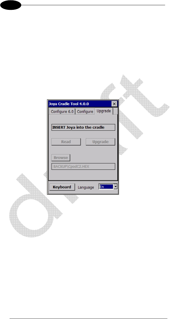
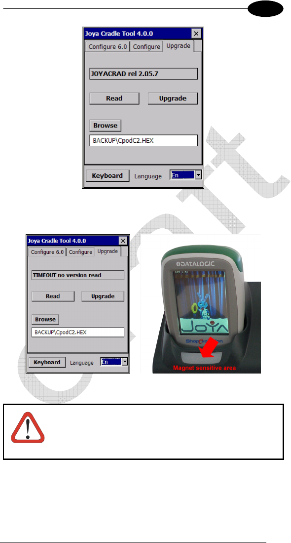
5.4.2 Starting program
Run JOYA_Cradle_Tool application, select the tab Upgrade by using the upper
left key or the touch screen
DATALOGIC JOYA™ X2
96
1 5
The screen displays the JOYA Cradle Tool version and the mode to interact
with the cradle (Read or Upgrade).
Use the touch screen or:
• Use the upper left key (F1) to select the tab.
• Use the upper right key (F2) to browse in the screen.
• Use the “e” key (ENTER) to quit.
• Use the “=” key (ESC) to select the language (when language is
focused).
5.4.3 Reading firmware version
Select the “Read”. JOYA Cradle Tool will display the message:
Insert in any cradle’s slot and the result will look as:
JOYA CRADLE DISPENSER
97
5
Cradle locks terminal in the slot and unlock after a successful reading. If read
fails, unlock the terminal by approaching a magnet to the sensitive area (see
picture below).
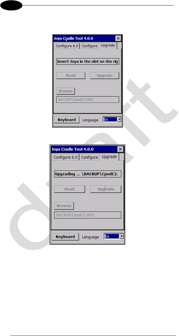
5.4.4 Firmware update procedure
This is a very uncommon procedure. To perform the
firmware update you should be advised by Datalogic which
will provide the upgrading firmware file CpodC2.HEX
CAUTION
Copy in the \Backup folder the file
• CpodC2.HEX (cradle’s latest firmware provided by Datalogic)
DATALOGIC JOYA™ X2
98
1 5
Select the “Upgrade” key and insert the terminal into the rightmost slot of the
cradle.
The cradle locks the terminal and JOYA Cradle Tool transfer firmware.
During this period, slot led flashes. At the end, the terminal top flashes three
times; approach a magnet to the sensitive area to unlock and extract the
terminal.
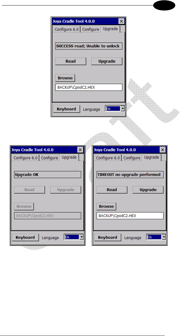
JOYA CRADLE DISPENSER
99
5
JOYA Cradle Tool shows a suitable message to inform user if update is
correctly completed or an error has been occurred.

DATALOGIC JOYA™ X2
10
0
1 5
5.5 JOYA™X2/JOYA CRADLE DISPENSER CONNECTION
JOYA Cradle Dispenser is equipped with an electrical-serial connection, used
to exchange command and response with JOYA™ X2. The communications
between the terminal inserted into the slot and the slot itself are performed by
means of a special “RPC like command-response” protocol.
5.6 CONFIGURATION
JOYA Cradle Dispenser should be previously configured using an apposite
program: JOYA Cradle Tool (see SDK Help for more information).
In a typical application there is the need to identify in a unique way each cradle
slot, in order to be able to perform selective operations. This requirement is
satisfied by each JOYA Cradle Dispenser slot, by means of a set of four
parameters, called Config Parameters:
Slot ID: is a string of 2 bytes
Dispenser ID: is string of 1 byte
IP address: is a string of …bytes
Port ID: is a string of 2 bytes
Using this four byte strings it is possible to setup and identify each slot in a
unique way.
This Config Parameters are stored in the permanent memory location
dedicated of each slot. They can be configured making use of the JOYA Cradle
Tool and they can be read by a well inserted JOYA™ X2.
5.7 USE AND FUNCTIONING
Insert a JOYA™ X2 inside a slot, JOYA Cradle Dispenser will lock the JOYA™
X2, when electrical connectors are contacted.
To unlock JOYA™ X2, approach a magnet to the sensitive area and extract the
JOYA™ X2.

JOYA CRADLE DISPENSER
101
5
All other commands could be developed by developers using JOYA SDK.

DATALOGIC JOYA™ X2
10
2
1 6
6 TECHNICAL FEATURES
6.1 JOYA
TM
X2 TECHNICAL DATASHEET
WIRELESS COMMUNICATIONS
LOCAL AREA
NETWORK (WLAN) IEEE 802.11 b/g/n; WiFi Security Standards, WEP,
WPA, TKIP, WPA2, CCX 4 compatible.
DECODING CAPABILITY
1D / LINEAR CODES Auto discriminates all standard 1D codes including
GS1 DataBar™ linear codes.
ELECTRICAL
BATTERY* Removable battery pack with rechargeable Li-polymer
batteries
ENVIRONMENTAL
DROP
RESISTANCE** Withstands drops from 1.2 meters onto concrete -
3.94 feet.
TEMPERATURE Operating: 0 to 40 ºC / 32 to 104 ºF.
INTERFACES
INTERFACES USB 1.1 Client (with standard micro USB connector)
It is not possible to use the USB when the device is
inserted in a wall mounted cradle.
PHYSICAL CHARACTERISTICS
BUMPERS Top and bottom rubber bumpers (lighting on top
bumper); standard available colours: Blue, Green,
Red, Orange.
DIMENSIONS Dimensions 149 x 73 x 44 mm - 5.86 x 2.87 x 1.73 inc
DISPLAY
JOYA™ X2 Basic: Display 2.8 inches high-contrast
colours graphic TFT LCD, 65k colors, 320 x240 pixels
QVGA.
JOYA™ X2 Plus: Display 2.8 inches high-contrast
colour graphic TFT LCD, 65k colours, 320 x240 pixels
QVGA Touch screen 4-wire resistive touch panel.
KEYBOARD 6 (six) fully programmable keys in standard available
colours: Blue, Green, Red, Orange.
TOP COVER In-mould decorated plastic cover (optionally
customizable).
WEIGHT 255 g (with battery) - 0.562 lb.

TECHNICAL FEATURES
103
6
READING PERFORMANCE
READER 1D Linear CCD imager engine; Scan rate: 50
scans/sec
READING INDICATORS Beeper (Polyphonic audio codec); Green Spot
“On Code” good reading feedback (Datalogic
patented feature).
SAFETY & REGULATORY
AGENCY APPROVALS The product meets necessary safety and
regulatory approvals for its intended use.
ENVIRONMENTAL
COMPLIANCE Complies to EU RoHS.
SOFTWARE
CONFIGURATION AND
MAINTENANCE
Wavelink Avalanche® device management pre-
licensed, available upon request.
Datalogic Configuration Utility (DCU).
DEVELOPMENT SDK Suite available upon request.
SYSTEM
MEMORY
JOYA™ X2 Basic: System RAM: 128 MB;
System Flash: 512 MB Flash Disc JOYA™ X2
Plus: System RAM: 128 MB; System Flash: 512
MB Flash Disk; 4 GB additional Flash.
MICROPROCESSOR XScale™ PXA310 @ 624 MHz; 32 bit.
OPERATING SYSTEM Microsoft Windows CE 6.0.
*JOYA X2 should be charged at an ambient temperature between 0 - 35º C to achieve the
maximum charging rate. Never charge the main device or spare batteries in a closed space where
excessive heat can build up Close to the limits of the working temperature, some display and/or
battery performance degradation may occur. Multiple rapid humidity and/or temperature variations
may cause condensing.
** Multiple drops can permanently damage the device.
7 TEST CODES

Pag. 104
Test codes here.

105

Pag. 106
8 GLOSSARY
Access Point
A device that provides transparent access between Ethernet wired networks
and IEEE 802.11 interoperable radio-equipped mobile units. Hand-held mobile
computers, PDAs or other devices equipped with radio cards, communicate
with wired networks using Access Points (AP). The mobile unit (mobile
computer) may roam among the APs in the same subnet while maintaining a
continuous, seamless connection to the wired network.
Barcode
A pattern of variable-width bars and spaces which represents numeric or
alphanumeric data in binary form. The general format of a barcode symbol
consists of a leading margin, start character, data or message character, check
character (if any), stop character, and trailing margin. Within this framework,
each recognizable symbology uses its own unique format.
Baud Rate
A measure for data transmission speed.
Bit
Binary digit. One bit is the basic unit of binary information. Generally, eight
consecutive bits compose one byte of data. The pattern of 0 and 1 values
within the byte determines its meaning.
Byte
On an addressable boundary, eight adjacent binary digits (0 and 1) combined in
a pattern to represent a specific character or numeric value. Bits are numbered
from the right, 0 through 7, with bit 0 the low-order bit. One byte in memory can
be used to store one ASCII character.
Decode
To recognize a bar code symbology (e.g., Codabar, Code 128, Code 3 of 9,
UPC/EAN, etc.) and analyze the content of the bar code scanned.
EEPROM
Electrically Erasable Programmable Read-Only Memory. An on-board non-
volatile memory chip.
Flash Disk
Non-volatile memory for storing application and configuration files.
Host
A computer that serves other mobile computers in a network, providing
services such as network control, database access, special programs,
supervisory programs, or programming languages.

107
Liquid Crystal Display (LCD)
A display that uses liquid crystal sealed between two glass plates. The crystals
are excited by precise electrical charges, causing them to reflect light outside
according to their bias. They use little electricity and react relatively quickly.
They require external light to reflect their information to the user.
Light Emitting Diode (LED)
A low power electronic light source commonly used as an indicator light. It uses
less power than an incandescent light bulb but more than a Liquid Crystal
Display (LCD).
RAM
Random Access Memory. Data in RAM can be accessed in random order, and
quickly written and read.
RF
Radio Frequency.
RTC
Real Time Clock.

INDEX
A
Accessories; 17
ActiveSync® Remote; 65
B
Backup Directory File Management;
70
Bluetooth® Manager Device Setup;
66
C
Charging the Batteries; 75
Cleaning the Mobile Computer; 80
Connections; 18
Control Panel; 57
Conventions; 1
D
Data Capture; 41
Data Capture Configuration; 48
DATALOGIC CONFIGURATION
UTILITY; 74
Datalogic JOYA™ X2 Description;
15
Description of the Keys; 44
E
End User License Agreement; v
F
Firmware Update; 72
FTP Server Setup; 69
G
General View; 13
Glossary; 104
I
Imager Data Capture; 41
J
JOYA cradle dispenser; 81
M
Maintenance; 75
Microsoft® ActiveSync®; 65
Microsoft® Mobile Device Center®;
65
Model Description; 15
P
Package Contents; 17
Patents; 10
R
Radio Compliance; 6
Reference Documentation; 1
References; 1
Registry; 57
Replacing the Batteries; 76
Resetting the JOYA™ X2; 45
S
Safety Regulations; 2
Startup; 22
Status Indicators; 47
Stylus Calibration; 64
Summit Radio Card; 58
T
Taskbar; 47
Technical Features; 99
Test Codes; 101
U
USB Connection; 18
Using the Stylus; 40
W
WEEE Compliance; 10

109
Windows Connections; 65
WLAN Connection; 20
WPAN Connections; 21
DRAFT

DRAFT

www.datalogic.com
© 2014 Datalogic ADC, Inc.
All rights reserved.
Datalogic and the Datalogic logo are registered trademarks of Datalogic
S.p.A. in many countries, including the U.S.A. and the E.U.
Datalogic ADC, S.r.l.
Via S. Vitalino, 13
40012 Lippo di Calderara di Reno
Bologna - Italy
Telephone: (+39) 051-3147011
Fax: (+39) 051-3147205
08/14