Datalogic S r l RHINOIIWIN 802.11ag/draft 802.11n WLAN PCI-E Minicard User Manual Rev 03 171030
Datalogic S.r.l. 802.11ag/draft 802.11n WLAN PCI-E Minicard Rev 03 171030
User Manual-Rev.03(171030)

Datasheet
SDC‐PE15N

SDC‐PE15N
Datasheet
2
CONTENTS
Scope............................................................................................................................................................3
Specifications...............................................................................................................................................3
PinDefinitions.............................................................................................................................................5
MechanicalSpecifications...........................................................................................................................7
ConnectorOverview................................................................................................................................7
Mounting..................................................................................................................................................7
ESDConsideration...................................................................................................................................7
RFLayoutDesignGuidelines......................................................................................................................7
Regulatory....................................................................................................................................................8
CertifiedAntennas...................................................................................................................................9
DocumentationRequirements...............................................................................................................9
FCC......................................................................................................................................................10
IndustryCanada................................................................................................................................11

SDC‐PE15N
Datasheet
3
SCOPE
ThisdocumentdescribeskeyhardwareaspectsoftheSDC‐PE15NembeddedwirelessLANmodule.This
documentisintendedtoassistdevicemanufacturersandrelatedpartieswithintegrationofthismodule
intotheirhostdevices.Datainthisdocumentaredrawnfromanumberofsourcesandincludes
informationfoundintheBroadcomBCM4322datasheetissuedinAugustof2008.
Theinformationinthisdocumentissubjecttochangewithoutnotice.PleasecontactLairdorvisit
thePE15NpageoftheLairdwebsitetoobtainthemostrecentversionofthisdocument.
SPECIFICATIONS
FeatureDescription
SystemInterface32‐bitPeripheralComponentInterconnectExpress(PCIe)MiniCard
with52pinedgeconnector
AntennaInterface2U.FL(Hirose)connectorsfor2x2MIMOsupport
ChipSetBroadcomBCM4322
InputPowerRequirements3.3VDC+/‐10%
CurrentConsumption
(Atmaximumtransmitpower
setting)
Transmit:600mA(1980mW)
Receive:91mA(300mW)
Standby:3mA(10mW)
OperatingTemperature‐30°to75°C(‐22°to167°F)
OperatingHumidity10to90%(non‐condensing)
StorageTemperature‐40°to80°C(‐40°to176°F)
StorageHumidity10to90%(non‐condensing)
MaximumElectrostaticDischarge4kV
Length51mm(2.01in.)
Width30mm(1.18in.)
Thickness3.3mm(0.13in.)
Weight9g(0.3oz.)
Mounting52pinedgeconnector
2ThroughHoles(non‐metallicscrewrecommended)
WirelessMediaDirectSequence‐SpreadSpectrum(DSSS)
OrthogonalFrequencyDivisionalMultiplexing(OFDM)
MediaAccessProtocolCarriersensemultipleaccesswithcollisionavoidance(CSMA/CA)
NetworkArchitectureTypesInfrastructureandadhoc
NetworkStandardsIEEE802.11a,802.11b,802.11d,802.11g,802.11h,802.11i,802.11n
DataRatesSupported802.11a(OFDM):6,9,12,18,24,36,48,54
802.11b(DSSS):1,2,5.5,11
802.11g(OFDM):6,9,12,18,24,36,48,54
802.11n(OFDM,20‐MHzchannels):14,29,43,58,87,116,130,144
802.11n(OFDM40‐MHzchannels):30,60,90,120,180,240,270,
300
ModulationBPSK@1,6,9,14,30Mbps

SDC‐PE15N
Datasheet
4
FeatureDescription
QPSK@2,12,18,29,43,60,90Mbps
CCK@5.5,11Mbps
16‐QAM@24,36,58,87,120,180Mbps
64‐QAM@48,54,116,130,144,240,270,300Mbps
RegulatoryDomainSupportFCC(Americas,PartsofAsiaandMiddleEast)
ETSI(Europe,MiddleEast,AfricaandPartsofAsia)
MIC(formerlyTELEC)(Japan)
KCC(Korea)
2.4GHzFrequencyBandsETSI
2.4GHzto2.483GHz
MIC
2.4GHzto2.495GHz
FCC
2.4GHzto2.473GHz
KCC
2.4GHzto2.483GHz
5GHzFrequencyBandsETSI
5.15GHzto5.35GHz
5.47GHzto5.725GHz
MIC
5.15GHzto5.35GHz
FCC
5.15GHzto5.35GHz
5.47GHzto5.725GHz
5.725GHzto5.82GHz
KCC
5.15GHzto5.35GHz
5.725GHzto5.82GHz
2.4GHz,20MHz‐wideOperating
Channels
ETSI:13(3non‐overlapping)
FCC:11(3non‐overlapping)
MIC:14(4non‐overlapping)
KCC:13(3non‐overlapping)
5GHz,20MHz‐wideOperating
Channels
ETSI:19non‐overlapping
FCC:23non‐overlapping
MIC:8non‐overlapping
KCC:12non‐overlapping
5GHz,40MHz‐wideOperating
Channels
ETSI:9non‐overlapping
FCC:11non‐overlapping
MIC:4non‐overlapping
OperatingSystemsSupportedWindowsXPProfessionalandEmbedded
ComplianceETSIRegulatoryDomain
EN300328
EN301489
EN301893(R&TTEDirective3.2)/EN301893(DFSTestReport)
EN62311:2008
EN60950‐1
EU2002/95/EC(RoHS)
FCCRegulatoryDomain
Part15.247SubpartC
Part15.407SubpartE
IndustryCanada
RSS‐210
MICRegulatoryDomain
Article2Item19,CategoryWW(2.4GhzChannels1‐13)
Article2Item19‐2,CategoryGZ(2.4GHzChannel14)
Article3Item19‐3,CategoryXW(5150‐5250W52&5250‐5350
W53)

SDC‐PE15N
Datasheet
5
FeatureDescription
NCC
Certification
CertificationsWi‐FiAlliance
802.11a,802.11b,802.11g,802.11n
WPAEnterprise
WPA2Enterprise
CiscoCompatibleExtensions(Version4)
Warranty3‐YearWarranty
Allspecificationsaresubjecttochangewithoutnotice
PINDEFINITIONS
Pin#Pin
NameI/OPower
TypeDescription
1WL_GPIO_1OVDDIOWakeonWireless–Notcurrentlysupportedinthe
software.Maybeleftopen
2VCC3_3 3.3VModulePower
3WLAN_ACTIVEOVDDIO
OutputtoBTdevice.Whenhigh,indicatesthatWLANis
transmittingorreceiving.
Donotconnectwhennotused
4GNDGround
5BT_ACTIVEIVDDIO
InputfromBTdevice.
Whenhigh,indicatesBluetoothistransmitting
orreceiving.TheSummitradiodoesnottransmitwhen
BT_ACTIVEishigh.
TietoGNDwhennotinuse
6NoConnect NoConnect.NotUsed.LeaveOpen(Float)
7CLKREQ_L Referenceclockrequestsignal
8NoConnect NotUsed.LeaveOpen(Float)
9GNDGround
10NoConnect NotUsed.LeaveOpen(Float)
11REFCLK_N Differentialreferenceclock
12NoConnect NotUsed.LeaveOpen(Float)
13REFCLK_P Differentialreferenceclock
14NoConnect NotUsed.LeaveOpen(Float)
15GNDGround
16NoConnect NotUsed.LeaveOpen(Float)
17NoConnect NotUsed.LeaveOpen(Float)
18GNDGround
19NoConnect NotUsed.LeaveOpen(Float)
20RF_DISABLE_L ModuleDisable

SDC‐PE15N
Datasheet
6
Pin#Pin
NameI/OPower
TypeDescription
21GNDGround
22PERST_L ModuleReset
23PETn0Differentialreceive
24VAUX_3_3 Auxiliary3.3VModulePower
25PETp0Differentialreceive
26GNDGround
27GNDGround
28NoConnect NoConnect.NotUsed.LeaveOpen(Float)
29GNDGround
30NoConnect NotUsed.LeaveOpen(Float)
31PERn0Differentialtransmit
32NoConnect NotUsed.LeaveOpen(Float)
33PERp0Differentialtransmit
34GNDGround
35GNDGround
36NoConnect NotUsed.LeaveOpen(Float)
37GNDGround
38NoConnect NotUsed.LeaveOpen(Float)
39VCC3_3 Primary3.3VModulePower
40GNDGround
41VCC3_3 Primary3.3VModulePower
42NoConnect NotUsed.LeaveOpen(Float)
43NoConnect NotUsed.LeaveOpen(Float)
44WL_LED_ACTOVDDIOWLANLEDActivityIndicator
45NoConnect NotUsed.LeaveOpen(Float)
46NoConnect NotUsed.LeaveOpen(Float)
47NoConnect NotUsed.LeaveOpen(Float)
48NoConnect NoConnect.NotUsed.LeaveOpen(Float)
49NoConnect NotUsed.LeaveOpen(Float)
50GNDGround
51NoConnect NotUsed.LeaveOpen(Float)
52VCC3_3 Primary3.3VModulePower
SDC‐PE15N
Datasheet
7
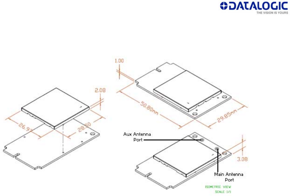
MECHANICALSPECIFICATIONS
ConnectorOverview
Mounting
TheSDC‐PE15NisfullycompliantwiththePCIefulllengthMiniCardmechanicalspecifications.Assuch,
itmaybeconnectedtothehostdeviceviaanystandards‐complianthostconnector.Itmaybemounted
tohostdevicesusingavarietyofstandards‐compliantlatchesandorviathetwomountingholeslocated
onthetopendofthedevice.
ESDConsideration
ThetwomountingholesarealsoforthepurposeofESD(electrostaticdischarge)consideration.To
handlemaximumESDlevels,twoscrewsmustbeusedontheSDC‐PE15Nwithpropergrounding
(connectedtothecustomer’smainboardgroundandthecasegroundofthedevice).
RFLAYOUTDESIGNGUIDELINES
ThefollowingisalistofRFlayoutdesignguidelinesandrecommendationwheninstallingaSummitradio
intoyourdevice.Pleasenotethatbecauseeachdeviceisdifferent,Summitcannotapproveand/or
guaranteetheoutcomeofyourspecificdesign.
Donotrunantennacablesdirectlyaboveordirectlybelowtheradio.
Donotplaceanypartsorrunanyhighspeeddigitallinesbelowtheradio.
Ifthereareotherradiosortransmitterslocatedonthedevice(suchasaBluetoothradio),place
thedevicesasfarapartfromeachotheraspossible.
Ensurethatthereisthemaximumallowablespacingseparatingtheantennaconnectorsonthe
Summitradiofromtheantenna.Inaddition,donotplaceantennasdirectlyaboveordirectly
belowtheradio.

SDC‐PE15N
Datasheet
8
Summitrecommendstheuseofadoubleshielded32AWGcablefortheconnectionbetween
theradioandtheantennaelements.
REGULATORY
Note:Operationinthe5150‐5250MHzbandislimitedtoindooruseonly.
Remarque:Lefonctionnementdanslabande5150‐5250MHzestlimitéàl'utilisationàl'intérieur
seulement.
SDC‐PE15N
Datasheet
9
CertifiedAntennas
TheSDC‐PE15NprovidestwoHiroseU.FLtypeantennaconnectorstosupporttransmitandreceive
diversity.Forsingleantenna,non‐diversityapplications,OEMsareadvisedtousetheMain(notAux)
antennaconnectorandshoulddisabletransmitandreceivediversityfromtheGlobaltaboftheSummit
ClientUtility(SCU)softwareutility.
Notice:Themoduleisprofessionallyinstalleddeviceandinstalledinindustrycomputerthatisgenerally
forindustrialuse.Thedevicecannotbesoldretail,tothegeneralpublicorbymailorder.Itmustbesold
todealersorhavestrictmarketingcontrol(suchasDatalogicS.r.l.andSOREDItouchsystemGmbH).
ThemodulemustbeinstalledbyaspecifiedinstallersthatrequireapprovalinstallationbyDatalogicS.r.l.
andSOREDItouchsystemGmbH.
Duetothismoduleisaprofessionalinstallationdevice,onlytheantennaslistedbelowareallowedto
use.
ModelTypeConnector
2400~2500MHz5150~5875MHz
HUBER+SUHNER
1399.99.0124 PCB
Antenna
includes
cable
pigtail,
terminated
by
connector
U.FL
1dBi(2.4‐2.5GHz),1dBi(5.15‐
5.875GHz)
ModelTypeConnector
2400~2500MHz2500~2700MHz
3400~3700MHz4900~5470MHz
5470~5935MHz
HUBER+SUHNER
1399.17.0106
Sencity®
Omni‐S
Antenna
N,50jack
(female)
6dBi(2.4‐2.5GHz),6dBi(2.5‐2.7GHz)
7dBi(3.4‐3.7GHz),8dBi(4.9‐5.47GHz)
8dBi(5.47‐5.935)
Note:TheformaltestreportsfortheSDC‐PE15Nshowtransmitpowerwasdecreasedtoless
than100%on2.4GHzedgechannels.Summithasmadethesetransmitpowerreductions
infirmwarefortheedgechannels.Integratorsdonotneedtoreducetransmitpowerona
channel‐by‐channelbasistoaccountforbandedgeregulations.
Antennasofdifferingtypesandhighergainsmaybeintegratedaswell.WiththeSummitManufacturing
Utilitysoftwareutility,OEMsmayreducethetransmitpoweroftheSDC‐PE15Ntoaccountforhigher
antennagainwhennecessary.Insomecases,OEMsmaybeabletoreducecertificationeffortsbyusing
antennasthatareofliketypeandequalorlessergaintotheabovelistedantennas.
DocumentationRequirements
Inordertomaintainregulatorycompliance,whenintegratingtheSDC‐PE15Nintoahostdeviceand
leveragingSummit’sgrantsandcertifications,itisnecessarytomeetthedocumentationrequirements
setforthbytheapplicableregulatoryagencies.Thefollowingsections(FCC,IndustryCanada,and

SDC‐PE15N
Datasheet
10
EuropeanUnion)outlinetheinformationthatmustbeincludedintheuser’sguideandexternallabels
forthehostdevicesintowhichtheSDC‐PE15Nisintegrated.
FCC
User’sGuideRequirements
AsoutlinedintheOperationalDescription,theSDC‐PE15NcomplieswithFCCPart15Rulesforasignal
ModularApproval.ToleverageSummit’sgrant,thetwoconditionsbelowmustbemetforthehost
deviceintowhichtheSDC‐PE15Nisintegrated:
1. Theantennaisinstalledwith20cmmaintainedbetweentheantennaandusers.
2. Thetransmittermoduleisnotco‐locatedwithanyothertransmitterorantennathatiscapableof
simultaneousoperation.Aslongasthetwoconditionsabovearemet,furthertransmittertesting
istypicallynotrequired.However,theOEMintegratorisstillresponsiblefortestingitsend‐
productforanyadditionalcompliancerequirementsrequiredwiththismoduleinstalled,suchas
(butnotlimitedto)digitaldeviceemissionsandPCperipheralrequirements.
I
MPORTANT
!
Intheeventthatthetwoconditionsabovecannotbemet(forexamplecertain
deviceconfigurationsorco‐locationwithanothertransmitter),thentheFCC
authorizationisnolongerconsideredvalidandtheFCCIDcannotbeusedonthe
finalproduct.Inthesecircumstances,theOEMintegratorwillberesponsiblefor
re‐evaluatingtheendproduct(includingthetransmitter)andobtainingaseparate
FCCauthorization.
WhenusingSummit’sFCCgrantfortheSDC‐PE15N,theintegratormustincludespecificinformationin
theuser’sguideforthedeviceintowhichtheSDC‐PE15Nisintegrated.Theintegratormustnotprovide
informationtotheenduserregardinghowtoinstallorremovethisRFmoduleintheuser’smanualof
thedeviceintowhichtheSDC‐PE15Nisintegrated.ThefollowingFCCstatementsmustbeaddedintheir
entiretyandwithoutmodificationintoaprominentplaceintheuser’sguideforthedeviceintowhich
theSDC‐PE15Nisintegrated:
“IMPORTANTNOTE:TocomplywithFCCRFexposurecompliancerequirements,theantennausedfor
thistransmittermustbeinstalledtoprovideaseparationdistanceofatleast20
cmfromallpersonsandmustnotbeco‐locatedoroperatinginconjunctionwith
anyotherantennaortransmitter.”
FederalCommunicationCommissionInterferenceStatement
ThisequipmenthasbeentestedandfoundtocomplywiththelimitsforaClassBdigitaldevice,
pursuanttoPart15oftheFCCRules.Theselimitsaredesignedtoprovidereasonableprotectionagainst
harmfulinterferenceinaresidentialinstallation.Thisequipmentgenerates,uses,andcanradiateradio
frequencyenergyand,ifnotinstalledandusedinaccordancewiththeinstructions,maycauseharmful
interferencetoradiocommunications.However,thereisnoguaranteethatinterferencewillnotoccur
inaparticularinstallation.Ifthisequipmentdoescauseharmfulinterferencetoradioortelevision
reception,whichcanbedeterminedbyturningtheequipmentoffandon,theuserisencouragedtotry
tocorrecttheinterferencebyoneofthefollowingmeasures:
1. Reorientorrelocatethereceivingantenna.

SDC‐PE15N
Datasheet
11
2. Increasetheseparationbetweentheequipmentandreceiver.
3. Connecttheequipmentintoanoutletonacircuitdifferentfromthattowhichthereceiveris
connected.
4. Consultthedealeroranexperiencedradio/TVtechnicianforhelp.
FCCCaution:Anychangesormodificationsnotexpresslyapprovedbythepartyresponsiblefor
compliancecouldvoidtheuser'sauthoritytooperatethisequipment.
ThisdevicecomplieswithPart15oftheFCCRules.Operationissubjecttothefollowingtwoconditions:
(1)Thisdevicemaynotcauseharmfulinterference,and(2)thisdevicemustacceptanyinterference
received,includinginterferencethatmaycauseundesiredoperation.
IMPORTANTNOTE:FCCRadiationExposureStatement:
ThisequipmentcomplieswithFCCradiationexposurelimitssetforthforanuncontrolled
environment.Thisequipmentshouldbeinstalledandoperatedwithminimumdistance
20cmbetweentheradiator&yourbody.
LabelingRequirements
Thefinalendproductmustbelabeledinavisibleareawiththefollowingnotice:
ContainsFCCID:U4G‐RHINOIIWIN
IndustryCanada
User’sGuideRequirements
ThisdevicecomplieswithIndustryCanada’slicense‐exemptRSSs.Operationissubjecttothefollowing
twoconditions:
1. Thisdevicemaynotcauseinterference;and
2. Thisdevicemustacceptanyinterference,includinginterferencethatmaycauseundesired
operationofthedevice.
LeprésentappareilestconformeauxCNRd’IndustrieCanadaapplicablesauxappareilsradioexemptsde
licence.L’exploitationestautoriséeauxdeuxconditionssuivantes:
1. l’appareilnedoitpasproduiredebrouillage;
2. l’utilisateurdel’appareildoitacceptertoutbrouillageradioélectriquesubi,mêmesilebrouillageest
susceptibled’encompromettrelefonctionnement.
AsoutlinedintheOperationalDescription,theSDC‐PE15NcomplieswithIndustryCanada(IC)rulesfora
signalModularApproval.ToleverageSummit’sgrant,thetwoconditionsbelowmustbemetforthe
hostdeviceintowhichtheSDC‐PE15Nisintegrated:
1. Theantennaisinstalledwith20cmmaintainedbetweentheantennaandusers.
2. Thetransmittermoduleisnotco‐locatedwithanyothertransmitterorantennathatiscapableof
simultaneousoperation.
Aslongasthetwoconditionsabovearemet,furthertransmittertestingistypicallynotrequired.
However,theOEMintegratorisstillresponsiblefortestingitsend‐productforanyadditional

SDC‐PE15N
Datasheet
12
compliancerequirementsrequiredwiththismoduleinstalled,suchas(butnotlimitedto)digitaldevice
emissionsandPCperipheralrequirements.
Commeindiquédansladescriptionopérationnelle,laSDC‐PE15Nestconformeauxrèglesd'Industrie
Canada(IC)pourunsignald'approbationmodulaire.PourtirerpartidelasubventionduSommet,les
deuxconditionssuivantesdoiventêtrerempliespourlepériphériquehôtedanslequellaSDC‐PE15Nest
intégrée:
1. l'antenneestinstalléeavec20cmentretenusparl'antenneetlesutilisateurs.
2. Lemoduleémetteurn'estpasco‐installéavecunautreémetteurouantennecapablede
fonctionnersimultanément.
Tantquelesdeuxconditionsci‐dessussontremplies,ilestpeuprobablequedenouveauxtestsde
développeurnesoientpasrequis.Cependant,l'intégrateurOEMesttoujoursresponsabledetesterson
produitfinalpourtouteslesexigencesdeconformitérequisesaveccemoduleinstallé,tellesque(mais
sanss'ylimiter)ÉmissionsdepériphériquesnumériquesetexigencesdepériphériquesPC.
I
MPORTANT
!
Intheeventthatthetwoconditionsabovecannotbemet(forexamplecertain
deviceconfigurationsorco‐locationwithanothertransmitter),thentheIC
authorizationisnolongerconsideredvalidandtheICIDcannotbeusedonthe
finalproduct.Inthesecircumstances,theOEMintegratorwillberesponsiblefor
re‐evaluatingtheendproduct(includingthetransmitter)andobtainingaseparate
ICauthorization.
SDC‐PE15N
Datasheet
13
WhenusingSummit’sICgrantfortheSDC‐PE15N,theintegratormustincludespecificinformationinthe
user’sguideforthedeviceintowhichtheSDC‐PE15Nisintegrated.Theintegratormustnotprovide
informationtotheenduserregardinghowtoinstallorremovethisRFmoduleintheuser’smanualof
thedeviceintowhichtheSDC‐PE15Nisintegrated.InadditiontotherequiredFCCstatementsoutlined
above,thefollowingICstatementsmustbeaddedintheirentiretyandwithoutmodificationintoa
prominentplaceintheuser’sguideforthedeviceintowhichtheSDC‐PE15Nisintegrated:
Topreventradiointerferencetothelicensedservice,thisdeviceisintendedtobeoperated
indoorsandawayfromwindowstoprovidemaximumshielding.Equipment(oritstransmit
antenna)thatisinstalledoutdoorsissubjecttolicensing.
Thisradiotransmitter(SDC‐PE15N–IC:3862E‐RHINOIIWIN)hasbeenapprovedbyIndustryCanadato
operatewiththeantennatypeslistedbelowwiththemaximumpermissiblegainindicated.Antenna
typesnotincludedinthislist,havingagaingreaterthanthemaximumgainindicatedforthattype,
arestrictlyprohibitedforusewiththisdevice.
Leprésentémetteurradio(SDC‐PE15N–IC:3862E‐RHINOIIWIN)aétéapprouvéparIndustrieCanada
pourfonctionneraveclestypesd'antenneénuméréscidessousetayantungainadmissiblemaximal.
Lestypesd'antennenoninclusdanscetteliste,etdontlegainestsupérieuraugainmaximalindiqué,
sontstrictementinterditspourl'exploitationdel'émetteur.
Notice:Themoduleisprofessionallyinstalleddeviceandinstalledinindustrycomputerthatisgenerally
forindustrialuse.Thedevicecannotbesoldretail,tothegeneralpublicorbymailorder.Itmustbesold
todealersorhavestrictmarketingcontr16ol(suchasDatalogicS.r.l.andSOREDItouchsystemGmbH).
ThemodulemustbeinstalledbyaspecifiedinstallersthatrequireapprovalinstallationbyDatalogicS.r.l.
andSOREDItouchsystemGmbH.
Duetothismoduleisaprofessionalinstallationdevice,onlytheantennaslistedbelowareallowedto
use.
ModelTypeConnector
2400~2500MHz5150~5875MHz
HUBER+SUHNER
1399.99.0124 PCB
Antenna
includes
cable
pigtail,
terminated
by
connector
U.FL
1dBi(2.4‐2.5GHz),1dBi(5.15‐
5.875GHz)
ModelTypeConnector
2400~2500MHz2500~2700MHz
3400~3700MHz4900~5470MHz
5470~5935MHz
HUBER+SUHNER
1399.17.0106
Sencity®
Omni‐S
N,50jack
(female)
6dBi(2.4‐2.5GHz),6dBi(2.5‐2.7GHz)
7dBi(3.4‐3.7GHz),8dBi(4.9‐5.47GHz)

SDC‐PE15N
Datasheet
14
Antenna 8dBi(5.47‐5.935)
LabelingRequirements
Thefinalendproductmustbelabeledinavisibleareawiththefollowingnotice:
ContainsICID:3862E‐RHINOIIWIN