Datalogic Scanning Magellan 1000I Users Manual
1000I to the manual 70ad80a4-07ce-47a1-8b73-a370dbfa2cee
2015-02-02
: Datalogic-Scanning Datalogic-Scanning-Magellan-1000I-Users-Manual-425467 datalogic-scanning-magellan-1000i-users-manual-425467 datalogic-scanning pdf
Open the PDF directly: View PDF ![]() .
.
Page Count: 176 [warning: Documents this large are best viewed by clicking the View PDF Link!]
- Getting Started
- General Features
- Interface Related Features
- Data Editing
- Symbologies
- 2D Symbologies & Advanced Decoding Features
- Product Specifications
- Cable Pinouts
- Alpha-Numeric Pad
- Default Settings
- Keyboard Function Key Mappings
- Host Commands
- Sample Symbols
Magellan
TM
1000i
On-Counter Presentation Omnidirectional Bar Code Reader
Product Reference Guide
Datalogic Scanning, Inc.
959 Terry Street
Eugene, Oregon 97402
Telephone: (541) 683-5700
Fax: (541) 345-7140
An Unpublished Work - All rights reserved. No part of the contents of this documentation or the procedures described
therein may be reproduced or transmitted in any form or by any means without prior written permission of Datalogic Scan-
ning, Inc. or its subsidiaries or affiliates ("Datalogic" or “Datalogic Scanning”). Owners of Datalogic products are hereby
granted a non-exclusive, revocable license to reproduce and transmit this documentation for the purchaser's own internal
business purposes. Purchaser shall not remove or alter any proprietary notices, including copyright notices, contained in this
documentation and shall ensure that all notices appear on any reproductions of the documentation.
Should future revisions of this manual be published, you can acquire printed versions by contacting your Datalogic repre-
sentative. Electronic versions may either be downloadable from the Datalogic website (www.scanning.datalogic.com) or
provided on appropriate media. If you visit our website and would like to make comments or suggestions about this or
other Datalogic publications, please let us know via the "Contact Datalogic" page.
Disclaimer
Datalogic has taken reasonable measures to provide information in this manual that is complete and accurate, however,
Datalogic reserves the right to change any specification at any time without prior notice.
Datalogic and the Datalogic logo are registered trademarks of Datalogic S.p.A. in many countries, including the U.S.A. and
the E.U. All other brand and product names referred to herein may be trademarks of their respective owners.
Magellan is a registered trademark of Datalogic Scanning, Inc. in many countries, including the U.S.A.
This product may be covered by one or more of the following patents: 4603262 • 4639606 • 4652750 • 4672215 • 4699447 • 4709369 •
4749879 • 4786798 • 4792666 • 4794240 • 4798943 • 4799164 • 4820911 • 4845349 • 4861972 • 4861973 • 4866257 • 4868836 • 4879456 •
4939355 • 4939356 • 4943127 • 4963719 • 4971176 • 4971177 • 4991692 • 5001406 • 5015831 • 5019697 • 5019698 • 5086879 • 5115120 •
5144118 • 5146463 • 5179270 • 5198649 • 5200597 • 5202784 • 5208449 • 5210397 • 5212371 • 5212372 • 5214270 • 5229590 • 5231293 •
5232185 • 5233169 • 5235168 • 5237161 • 5237162 • 5239165 • 5247161 • 5256864 • 5258604 • 5258699 • 5260554 • 5274219 • 5296689 •
5298728 • 5311000 • 5327451 • 5329103 • 5330370 • 5347113 • 5347121 • 5371361 • 5382783 • 5386105 • 5389917 • 5410108 • 5420410 •
5422472 • 5426507 • 5438187 • 5440110 • 5440111 • 5446271 • 5446749 • 5448050 • 5463211 • 5475206 • 5475207 • 5479011 • 5481098 •
5491328 • 5493108 • 5504350 • 5508505 • 5512740 • 5541397 • 5552593 • 5557095 • 5563402 • 5565668 • 5576531 • 5581707 • 5594231 •
5594441 • 5598070 • 5602376 • 5608201 • 5608399 • 5612529 • 5629510 • 5635699 • 5641958 • 5646391 • 5661435 • 5664231 • 5666045 •
5671374 • 5675138 • 5682028 • 5686716 • 5696370 • 5703347 • 5705802 • 5714750 • 5717194 • 5723852 • 5750976 • 5767502 • 5770847 •
5786581 • 5786585 • 5787103 • 5789732 • 5796222 • 5804809 • 5814803 • 5814804 • 5821721 • 5822343 • 5825009 • 5834708 • 5834750 •
5837983 • 5837988 • 5852286 • 5864129 • 5869827 • 5874722 • 5883370 • 5905249 • 5907147 • 5923023 • 5925868 • 5929421 • 5945670 •
5959284 • 5962838 • 5979769 • 6000619 • 6006991 • 6012639 • 6016135 • 6024284 • 6041374 • 6042012 • 6045044 • 6047889 • 6047894 •
6056198 • 6065676 • 6069696 • 6073849 • 6073851 • 6094288 • 6112993 • 6129279 • 6129282 • 6134039 • 6142376 • 6152368 • 6152372 •
6155488 • 6166375 • 6169614 • 6173894 • 6176429 • 6188500 • 6189784 • 6213397 • 6223986 • 6230975 • 6230976 • 6244510 • 6259545 •
6260763 • 6266175 • 6273336 • 6276605 • 6279829 • 6290134 • 6290135 • 6293467 • 6303927 • 6311895 • 6318634 • 6328216 • 6332576 •
6332577 • 6343741 • 6454168 • 6478224 • 6568598 • 6578765 • 6705527 • 6857567 • 6974084 • 6991169 • 7051940 • 7170414 • 7172123 •
7201322 • 7204422 • 7215493 • 7224540 • 7234641 • 7243850 • 7374092 • 7407096 • 601 26 118.6 • AU703547 • D312631 • D313590 •
D320011 • D320012 • D323492 • D330707 • D330708 • D349109 • D350127 • D350735 • D351149 • D351150 • D352936 • D352937 • D352938
• D352939 • D358588 • D361565 • D372234 • D374630 • D374869 • D375493 • D376357 • D377345 • D377346 • D377347 • D377348 •
D388075 • D446524 • EP0256296 • EP0260155 • EP0260156 • EP0295936 • EP0325469 • EP0349770 • EP0368254 • EP0442215 • EP0498366 •
EP0531645 • EP0663643 • EP0698251 • EP01330772 • GB2252333 • GB2284086 • GB2301691 • GB2304954 • GB2307093 • GB2308267 •
GB2308678 • GB2319103 • GB2333163 • GB2343079 • GB2344486 • GB2345568 • GB2354340 • ISR107546 • ISR118507 • ISR118508 •
JP1962823 • JP1971216 • JP2513442 • JP2732459 • JP2829331 • JP2953593 • JP2964278 • MEX185552 • MEX187245 • RE37166 • RE40.071 •
Other Patents Pending

Product Reference Guide
i-i
Table of Contents
About This Manual ............................................................................................................... 1-1
Manual Conventions ....................................................................................................... 1-1
Connecting the Scanner ....................................................................................................... 1-2
Programming ..................................................................................................................... 1-3
Using the Programming Barcodes .................................................................................... 1-3
Resetting the Standard Product Defaults ................................................................................ 1-3
LED and Beeper Indicators ................................................................................................... 1-4
Error Codes ........................................................................................................................ 1-5
Double Read Timeout .......................................................................................................... 2-1
Label Gone Timeout ............................................................................................................ 2-3
Productivity Index Reporting (PIR) ........................................................................................ 2-3
Sleep Mode ........................................................................................................................ 2-4
LED and Beeper Indicators ................................................................................................... 2-6
Power On Alert .............................................................................................................. 2-6
Good Read: When to Indicate .......................................................................................... 2-7
Good Read Beep Control ................................................................................................. 2-8
Good Read Beep Frequency ............................................................................................ 2-8
Good Read Beep Length ................................................................................................. 2-9
Good Read Beep Volume ...............................................................................................2-10
Scanning Features .............................................................................................................2-11
Targeted Scanning Mode ............................................................................ 2-11
Target Mode Active Time ...............................................................................................2-11
Target Mode Linger Time ...............................................................................................2-12
Wake Up Intensity ........................................................................................................2-13
Interface Selection .............................................................................................................. 3-3
Interface Features ............................................................................................................... 3-7
Obey/Ignore Host Commands ....................................................................... 3-7
Host Transmission Buffers ............................................................................ 3-8
RS-232 Interface Features .............................................................................................. 3-9
Hardware Flow Control .............................................................................. 3-11
Intercharacter Delay ................................................................................. 3-12
Software Flow Control ............................................................................... 3-13
Host Echo ................................................................................................ 3-14
Host Echo Quiet Interval ............................................................................ 3-15
Signal Voltage: Normal/TTL ........................................................................ 3-16
RS-232 Invert .......................................................................................... 3-17
Beep on ASCII BEL .................................................................................... 3-17
Beep on Not on File ................................................................................... 3-18
ACK NAK Options ...................................................................................... 3-19
ACK Character .......................................................................................... 3-20
NAK Character .......................................................................................... 3-20
Retry on ACK NAK Timeout ........................................................................ 3-21
ACK NAK Timeout Value ............................................................................. 3-21
ACK NAK Retry Count ................................................................................ 3-22
ACK NAK Error Handling ................................................................................................3-23
Transmission Failure Indication ................................................................... 3-24
USB-OEM Interface Features ..........................................................................................3-24
USB-OEM Device usage ............................................................................. 3-24
IBM ............................................................................................................................3-25
IBM Transmit Labels in Code 39 Format ....................................................... 3-25
Wand Emulation ...........................................................................................................3-26
Supported Symbologies ............................................................................. 3-26
Wand Emulation Barcode Format ................................................................ 3-26
Bar/Space Polarity .................................................................................... 3-27

i-ii Magellan® 1000i
Wand Idle State ........................................................................................ 3-27
Signal Speed ............................................................................................ 3-28
Transmit Trailing Noise .............................................................................. 3-28
Transmit Leading Noise ............................................................................. 3-29
Symbology Conversion .............................................................................. 3-29
Keyboard Wedge .......................................................................................................... 3-30
USB Keyboard ............................................................................................................. 3-30
Caps Lock State ........................................................................................ 3-32
Data Editing Overview ..........................................................................................................4-1
Please Keep In Mind... ....................................................................................................4-1
Global Prefix/Suffix .............................................................................................................. 4-2
AIM ID ...............................................................................................................................4-4
Label ID ............................................................................................................................. 4-5
Case Conversion ................................................................................................................4-12
Character Conversion ......................................................................................................... 4-13
UPC-A ................................................................................................................................ 5-1
Disable/Enable UPC-A .....................................................................................................5-1
Check Digit Transmission ................................................................................................5-2
Expand UPC-A to EAN-13 ................................................................................................5-2
Number System Transmission ..........................................................................................5-3
UPC-A Minimum Reads ...................................................................................................5-3
UPC-A In-store Minimum Reads .......................................................................................5-4
UPC-E ................................................................................................................................ 5-5
Disable/Enable UPC-E .....................................................................................................5-5
Check Digit Transmission ................................................................................................5-5
Number System Digit .....................................................................................................5-6
Expand to UPC-E to UPC-A ..............................................................................................5-6
Expand UPC-E to EAN13 .................................................................................................5-7
Minimum Reads .............................................................................................................5-7
GTIN ............................................................................................................................ 5-8
Expand UPC/EAN to GTIN ................................................................................................5-8
EAN-13 .............................................................................................................................. 5-9
Disable/Enable EAN-13 ...................................................................................................5-9
Check Digit Transmission ................................................................................................5-9
EAN-13 Flag 1 Character ............................................................................................... 5-10
ISBN .......................................................................................................................... 5-10
Minimum Reads ........................................................................................................... 5-11
EAN-8 .............................................................................................................................. 5-12
Disable/Enable EAN-8 ................................................................................................... 5-12
Check Digit Transmission .............................................................................................. 5-12
Minimum Reads ........................................................................................................... 5-13
Enable EAN Two-Label ........................................................................................................ 5-14
Add-ons ........................................................................................................................... 5-15
GS1 DataBar Omnidirectional / Stacked Omnidirectional ......................................................... 5-17
Disable/Enable GS1 DataBar Omnidirectional ................................................................... 5-17
UCC/EAN 128 Emulation ............................................................................................... 5-17
Minimum Reads ........................................................................................................... 5-18
GS1 DataBar Expanded / Expanded Stacked ......................................................................... 5-19
Disable/Enable GS1 DataBar Expanded ........................................................................... 5-19
GS1-128 Emulation ...................................................................................................... 5-19
Length Control ............................................................................................................. 5-20
GS1 DataBar Expanded Length 1, Length 2 Programming Instructions ................................ 5-21
Minimum Reads ........................................................................................................... 5-22
Coupon Read Control .................................................................................................... 5-23
GS1 DataBar Limited ......................................................................................................... 5-24
Disable/Enable GS1 DataBar Limited .............................................................................. 5-24
GS1-128 Emulation ...................................................................................................... 5-24
Minimum Reads ........................................................................................................... 5-25
Code 39 ........................................................................................................................... 5-26
Disable/Enable Code 39 ................................................................................................ 5-26
Check Character Calculation .......................................................................................... 5-26
Check Character Transmit ............................................................................................. 5-27

Product Reference Guide
i-iii
Start/Stop Characters ...................................................................................................5-27
Code 39 Full ASCII .......................................................................................................5-28
Length Control .............................................................................................................5-29
Code 39 Length 1, Length 2 Programming Instructions ......................................................5-30
Quiet Zones .................................................................................................................5-30
Code 39 Stitching .........................................................................................................5-31
Minimum Reads ............................................................................................................5-31
Pharmacode 39 ..................................................................................................................5-32
Disable/Enable Pharmacode 39 .......................................................................................5-32
Start/Stop Characters ...................................................................................................5-32
Check Character Transmit ..............................................................................................5-33
Code 128 ..........................................................................................................................5-34
Disable/Enable Code 128 ...............................................................................................5-34
Disable/Enable EAN 128 ................................................................................................5-34
Transmit Function Characters .........................................................................................5-35
Length Control .............................................................................................................5-36
Code 128 Length 1, Length 2 Programming Instructions ....................................................5-37
Code 128 Conversion to Code 39 ....................................................................................5-37
Code 128 Stitching .......................................................................................................5-38
Minimum Reads ............................................................................................................5-38
Interleaved 2 of 5 ..............................................................................................................5-39
Disable/Enable Interleaved 2 of 5 ...................................................................................5-39
Check Digit Calculation ..................................................................................................5-39
Check Digit Transmit .....................................................................................................5-40
Length Control .............................................................................................................5-41
Interleaved 2 of 5 Length 1, Length 2 Programming Instructions .........................................5-42
Interleaved 2 of 5 Stitching ............................................................................................5-43
Minimum Reads ............................................................................................................5-44
Codabar ............................................................................................................................5-45
Disable/Enable Codabar .................................................................................................5-45
Check Character Verification ..........................................................................................5-45
Check Character Transmit ..............................................................................................5-46
Length Control .............................................................................................................5-47
Codabar Length 1, Length 2 Programming Instructions ......................................................5-48
Quiet Zones ............................................................................................. 5-48
Start/Stop Character Type .............................................................................................5-49
Start/Stop Character Transmission ..................................................................................5-49
Start/Stop Character Match ...........................................................................................5-50
Codabar Stitching .........................................................................................................5-50
Minimum Reads ............................................................................................................5-51
Code 93 ............................................................................................................................5-52
Disable/Enable Code 93 .................................................................................................5-52
Length Control .............................................................................................................5-53
Code 93 Length 1, Length 2 Programming Instructions ......................................................5-54
Code 93 Stitching .........................................................................................................5-55
Minimum Reads ............................................................................................................5-55
MSI/Plessey ......................................................................................................................5-56
Disable/Enable MSI/Plessey ...........................................................................................5-56
Check Digit Verification .................................................................................................5-56
Check Digit Transmit .....................................................................................................5-57
Number of Check Characters ..........................................................................................5-57
Length Control .............................................................................................................5-58
MSI/Plessey Length 1, Length 2 Programming Instructions .................................................5-59
MSI/Plessey Stitching ....................................................................................................5-60
Minimum Reads ............................................................................................................5-61
Standard 2 of 5 .................................................................................................................5-62
Disable/Enable Standard 2 of 5 ......................................................................................5-62
Check Digit Verification .................................................................................................5-62
Check Digit Transmit .....................................................................................................5-63
Length Control .............................................................................................................5-64
Standard 2 of 5 Length 1, Length 2 Programming Instructions ............................................5-65
Standard 2 of 5 Stitching ...............................................................................................5-66

i-iv Magellan® 1000i
Minimum Reads ........................................................................................................... 5-67
2D Symbologies .................................................................................................................. 6-2
PDF 417 .......................................................................................................................6-2
Disable/Enable PDF 417 ............................................................................... 6-2
Length Control ........................................................................................... 6-3
PDF 417 Length 1, Length 2 Programming Instructions .................................... 6-4
Minimum Reads .......................................................................................... 6-5
Datamatrix ....................................................................................................................6-6
Disable/Enable Datamatrix ........................................................................... 6-6
Length Control ........................................................................................... 6-7
Datamatrix Length 1, Length 2 Programming Instructions ................................ 6-8
Minimum Reads .......................................................................................... 6-9
Image Capture ..................................................................................................................6-10
How to Capture an Image ............................................................................................. 6-10
Captured Image Format ................................................................................................ 6-10
Optical and Read Performance Parameters ..............................................................................A-1
Scanner Dimensions ............................................................................................................A-1
Physical Properties ...............................................................................................................A-2
Electrical Parameters ...........................................................................................................A-2
Environmental Parameters ....................................................................................................A-2
Other Parameters ................................................................................................................A-2
Standard Cable Pinouts (Primary Interface Cables) ...................................................................B-1
RS-232 .........................................................................................................................B-1
IBM Port 5B/9B/17 .........................................................................................................B-1
USB-OEM ......................................................................................................................B-2
USB, USB Keyboard & USB COM ......................................................................................B-2
Wand Emulation ............................................................................................................B-2
Keyboard Wedge ............................................................................................................B-2
Defaults by Symbology ........................................................................................................ D-1
Interface Default Exceptions ................................................................................................ D-2
IBM Interfaces .............................................................................................................. D-2
RS-232 Wincor/Nixdorf .................................................................................................. D-3
Wand Emulation ........................................................................................................... D-4
Keyboards .................................................................................................................... D-4
Keyboard Model Cross Reference ...........................................................................................E-1
Accepting RS-232 Commands ............................................................................................... F-1
Product Reference Guide
1-1
Chapter 1
Getting Started
The Magellan® 1000i Omni-Directional Imaging Scanner offers hands-free scanning for small,
easily handled items and handheld scanning for bulkier items. Its aggressive imaging perfor-
mance and intuitive operation reduces user training and speeds checkout for better customer
service.
About This Manual
This manual presents advanced user information which includes connection, programming,
product and cable specifications, and other useful references. For additional information, such
as installation, maintenance, troubleshooting and warranty information, see the Quick Refer-
ence Guide (QRG). Copies of other publications for this product are downloadable free of
charge from the website listed on the back cover of this manual.
On leaving the factory, units are programmed for the most common terminal and communica-
tions settings. If you need to change these settings, custom programming can be accomplished
by scanning the barcodes in this guide.
Bold text and a yellow-highlighted background indicates the most common default setting for a
feature/option.
Manual Conventions
The symbols listed below are used in this manual to notify the reader of key issues or procedures
that must be observed when using the scanner:
NOTE
Notes contain information necessary for prop-
erly diagnosing, repairing and operating the
scanner.
CAUTION
The CAUTION symbol advises you of actions
that could damage equipment or property.
Getting Started
1-2 Magellan
®
1000i
Connecting the Scanner
The scanner kit you ordered to match your interface should provide a compatible cable for your
installation. Use the appropriate instructions below to connect the scanner to the terminal, PC
or other host device.
Upon completing the connection via the appropriate interface instructions below, proceed to
the Interface Related Features section of this manual and scan the barcode to select the correct
interface type.
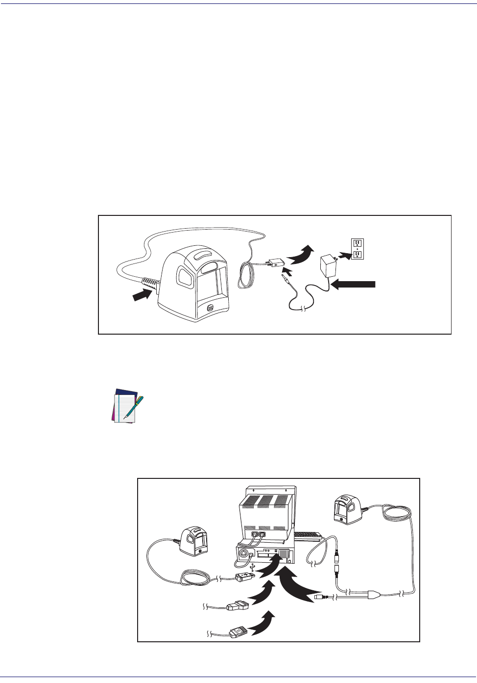
RS-232 Serial Connection —
Turn off power to the terminal/PC and connect the scanner
to the terminal/PC serial port via the RS-232 cable as shown in Figure 1. If the terminal will not
support POT (Power Off the Terminal) to supply scanner power, use the approved power supply
(AC Adapter). Plug the AC Adapter barrel connector into the socket on the RS-232 cable con-
nector and the AC Adapter plug into a standard power outlet.
Figure 1
. RS-232 Serial or USB Connection using A/C Adapter
USB Connection —
Connect the scanner to a USB port on the terminal/PC using the correct
USB cable for the interface type you ordered. Reference Figure 1 and Figure 2.
Figure 2. Other Connection Types
NOTE
USB installations may require a power connection via
an approved A/C Adapter as shown in Figure 1. For
example, this would be the case if the scanner is con-
nected along with a number of other devices to a non-
powered USB hub.
I/F Cable
Connect
Here A/C Adapter
(if needed)
For 220-230 VAC
adapters, the
cord must be
facing down as
shown in the
illustration. If
installed upwards,
it will pose an
undue strain on the
socket outlet.
To Host/Terminal
U
S
B
I
B
M
K
e
y
b
o
a
r
d
W
e
d
g
e
W
a
n
d
or...
or...
or...

Programming
Product Reference Guide
1-3
Wand Emulation Connection —
Connect the scanner to the appropriated port on the ter-
minal/PC using the correct cable for the interface type you ordered. Reference Figure 2.
IBM Connection —
Connect the scanner to the IBM port on the terminal/PC using the cor-
rect IBM cable. Reference Figure 2.
Keyboard Wedge Connection —
Before connection, turn off power to the terminal/PC.
The Keyboard Wedge cable has a ‘Y’ connection from the scanner. Connect the female to the
male end from the keyboard and the remaining end at the keyboard port at the terminal/PC.
Reference Figure 2.
Programming
The scanner is typically factory-configured with a set of default features standard to the interface
type you ordered. After scanning the interface barcode from the Interface Related Features sec-
tion, you can select other options and customize your scanner through use of the instructions
and programming barcodes available in that section and also the Data Editing and Symbologies
chapters of this manual.
Using the Programming Barcodes
This manual contains feature descriptions and barcodes which allow you to reconfigure your
scanner. Some programming barcode labels, like the label below for resetting defaults, require
only the scan of that single label to enact the change. Most of the programming labels in this
manual, however, require the scanner to be placed in Programming Mode prior to scanning
them. Scan a START/END barcode once to enterProgramming Mode. Once the scanner is in
Programming Mode, you can scan a number of parameter settings before scanning the START/
END barcode a second time, which will then accept your changes, exit Programming Mode and
return the scanner to normal operation.
Resetting the Standard Product Defaults
If you are unsure of what programming options are in your scanner, or you’ve changed some
options and want the factory settings restored, scan the Standard Product Default Settings bar-
code below. This will copy the factory configuration for the currently active interface to the cur-
rent configuration.
The programming section lists the factory default settings for each of the menu commands for
the standard RS-232 interface in BOLD text on the following pages. Exceptions to default set-
tings for the other interfaces can be found in Appendix D, Default Settings.
Standard Product Default Settings

Getting Started
1-4 Magellan
®
1000i
LED and Beeper Indicators
The scanner’s beeper sounds and its green LED illuminates to indicate various functions
or errors on the scanner. The tables below list these indications. One exception to the
behaviors listed in the tables is that the scanner’s functions are programmable, and may
or may not be turned on. For example, certain indications, such as the power-up beep
can be disabled using programming barcode labels.
Green LED Indications
LED
INDICATION INDICATION COMMENT
Power-on
indication Bright green flash Indicates the scanner has finished all its power up tests and is
now ready for ooperation.
Good Read
Indication Bright green flash Indicates a barcode has been read and decoded.
Scanner Ready Constant dim green The scanner is ready for operation.
Sleep Mode Constant green flash
(100mS on, 1900mS off)
The scanner is in Sleep Mode. To wake the scanner up, move
an object in front of its window or press the button atop the
unit.
Host Disable Constant green flash at 1 Hz
(100mS on, 900mS off)
The scanner is disabled due to receiving a disble command
from the POS terminal.
Diagnostics Varies (see "Error Codes" on
page 1-5 for more information)
The LED can provide diagnostic feedback if the scanner dis-
covers a problem during SelfTest.
BEEPER FUNCTIONS
BEEPER
INDICATION INDICATION COMMENT
Power On Beep Single beep
The Power-On LED indication is a configurable feature which
can be enabled or disabled. When enabled, this beep Indi-
cates the scanner has finished all its power up tests and is
now ready for operation.
Good Read
Indication Single beep
The good read beep indication is configurable. Options
include: Enable/disable, frequency, duration and volume. See
the Product Reference Guide (PRG) for more information.
Diagnostics Varies (see "Error Codes" on
page 1-5 for more information)
The Beeper can provide diagnostic feedback if the scanner
discovers a problem during SelfTest.
Programming
Mode
Indications
Varies (see the Product Reference
Guide for more information about
scanner programming)
The Beeper will sound as programming barcode labels are
scanned, indicating progress during scanner configuration.
Error Codes
Product Reference Guide
1-5
Error Codes
Upon startup, if the scanner flashes its indicator LED or sounds an unexpected series of beep
tones (other than normal power-up indications), this means the scanner has not passed its auto-
matic Selftest and has entered FRU1 isolation mode. If the scanner is reset or the trigger is
pulled, the sequence will be repeated. The following table describes the LED flashes/beep codes
associated with an error found.
1. Field Replaceable Unit (FRU)
NUMBER OF
LED FLASHES/
BEEPS
ERROR CORRECTIVE ACTION
1 Configuration
Contact Helpdesk for assistance
2Interface PCB
6 Main PCB
10 Button Error
12 Imager Module
13 Software ID
Failure
14 CPLD/Code
Mismatch

Getting Started
1-6 Magellan
®
1000i
NOTES
Product Reference Guide
2-1
Chapter 2
General Features
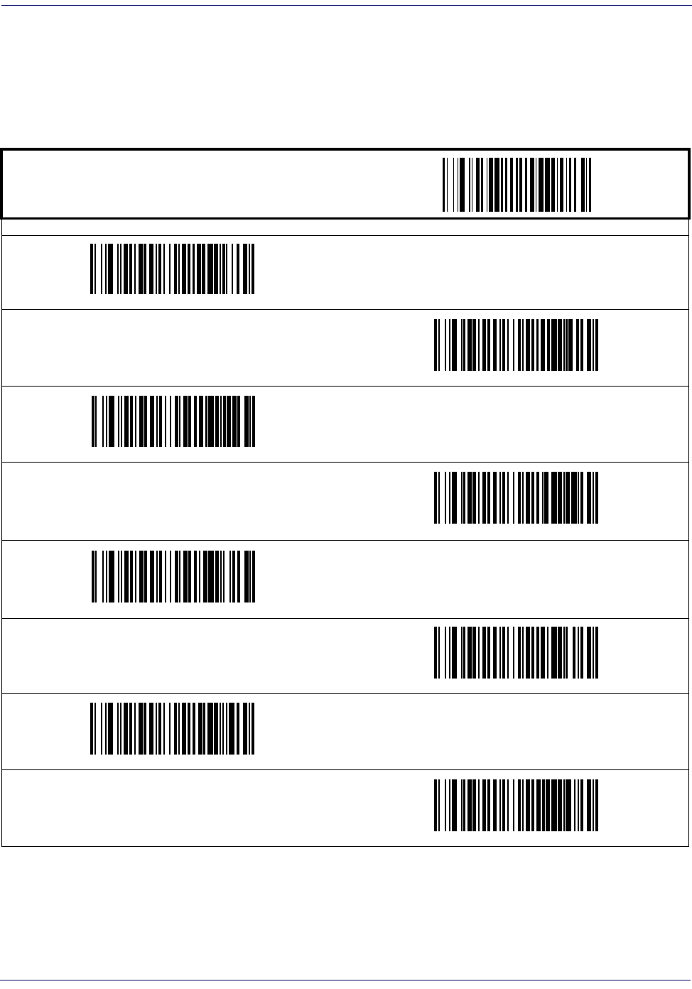
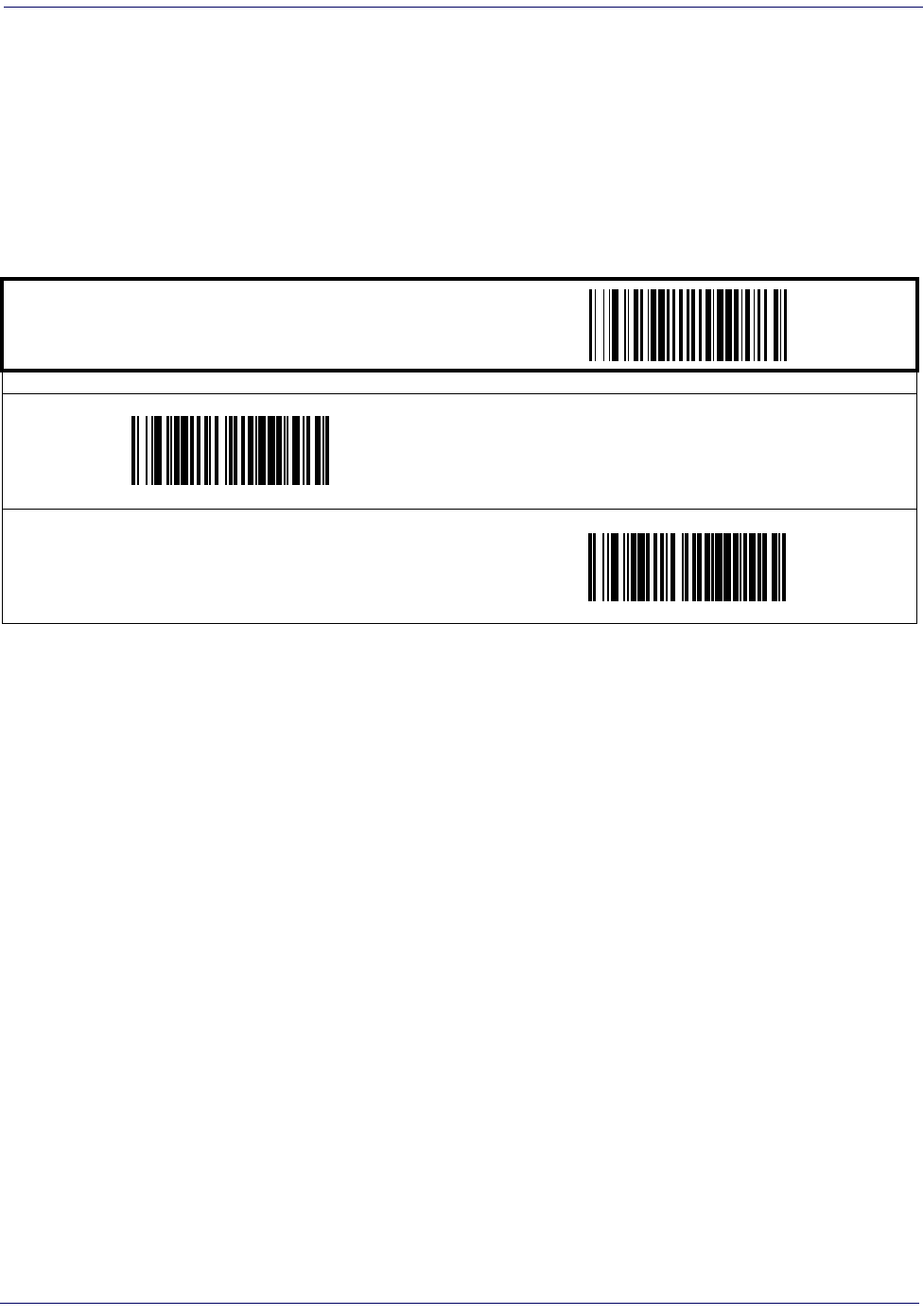
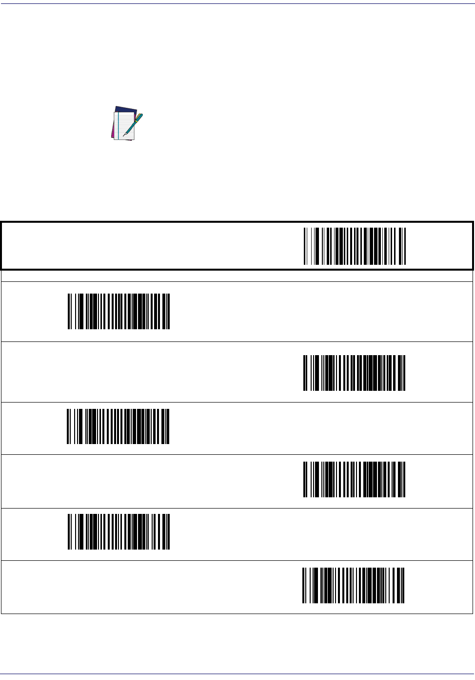
Double Read Timeout
The Double Read Timeout feature sets a time limit that determines how much time must pass
before reading the same label again (e.g. two identical items in succession).
START / END
PROGRAMMING BARCODES
0.1 Second
0.2 Second
0.3 Second
0.4 Second
DEFAULT
0.5 Second
0.6 Second

Label Gone Timeout
Product Reference Guide
2-3
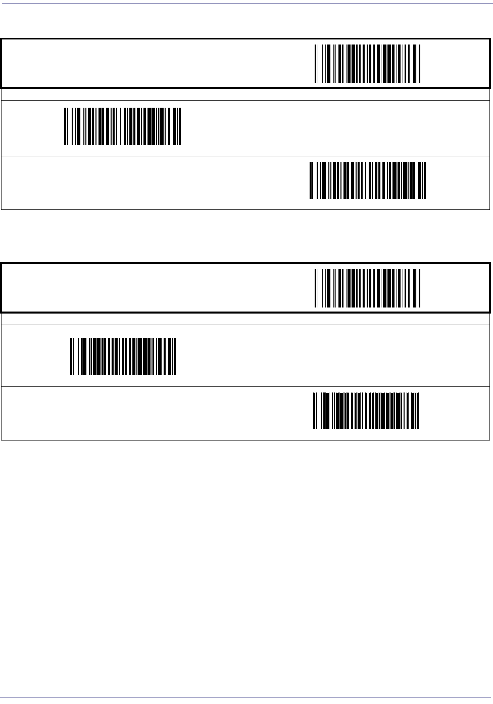
Label Gone Timeout
This feature sets the time after the last label segment is seen before the scanner prepares for a
new label.
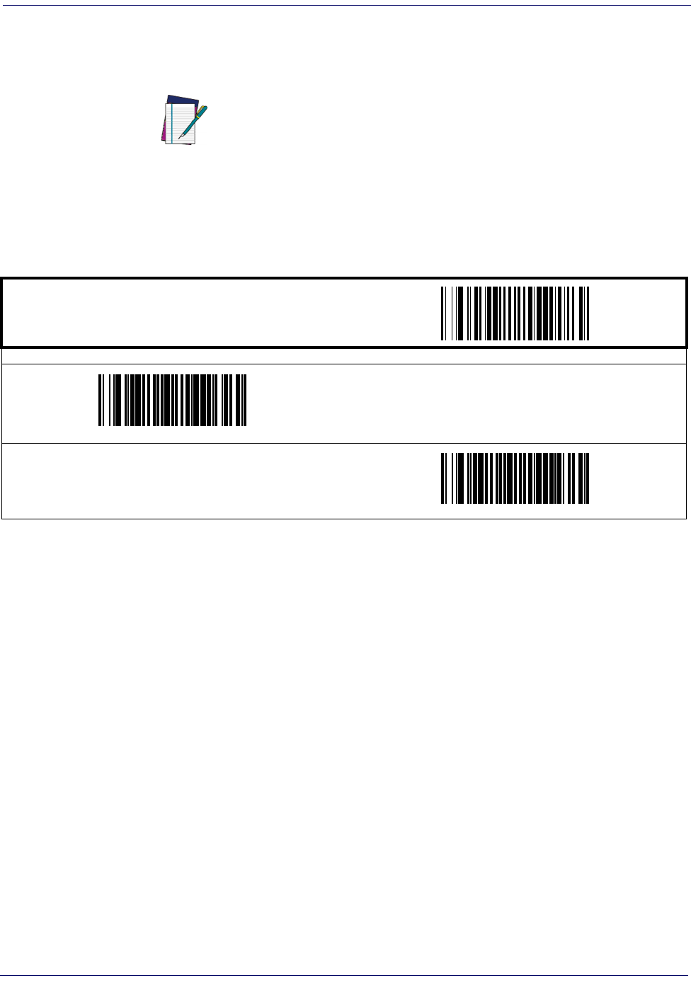
Productivity Index Reporting (PIR)
When PIR is enabled, label quality data is appended to decoded data before being presented to
the POS. The PIR feature allows the scanner to provide information to an external computer,
indicating how easy the label was to read.
START / END
PROGRAMMING BARCODES
Sets the label gone timeout duration using hex values from 000 to 255 in increments of ten milliseconds (10ms or 0.01 seconds). To
configure this feature, scan the “START/END” barcode above to place the unit in Programming Mode, then the “Set Label Gone Tim-
eout,” followed by the three digits (zero padded) from the Alphanumeric table in Appendix C, Alpha-Numeric Pad representing the
desired time value. Exit programming mode by scanning the “START/END” barcode again.
DEFAULT SETTING FOR THIS FEATURE: 320 milliseconds (032)
Set Label Gone Timeout
NOTE
This value-added feature is a factory-programmed
option. Contact your dealer for information about
upgrading your system to include this advanced
capability.
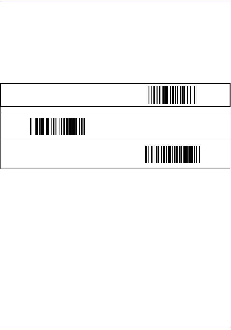
START / END
PROGRAMMING BARCODES
Disable
DEFAULT
Enable
General Features
2-4
Magellan
®
1000i
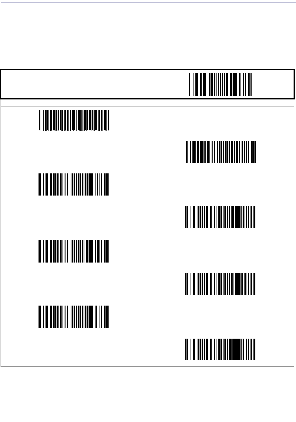
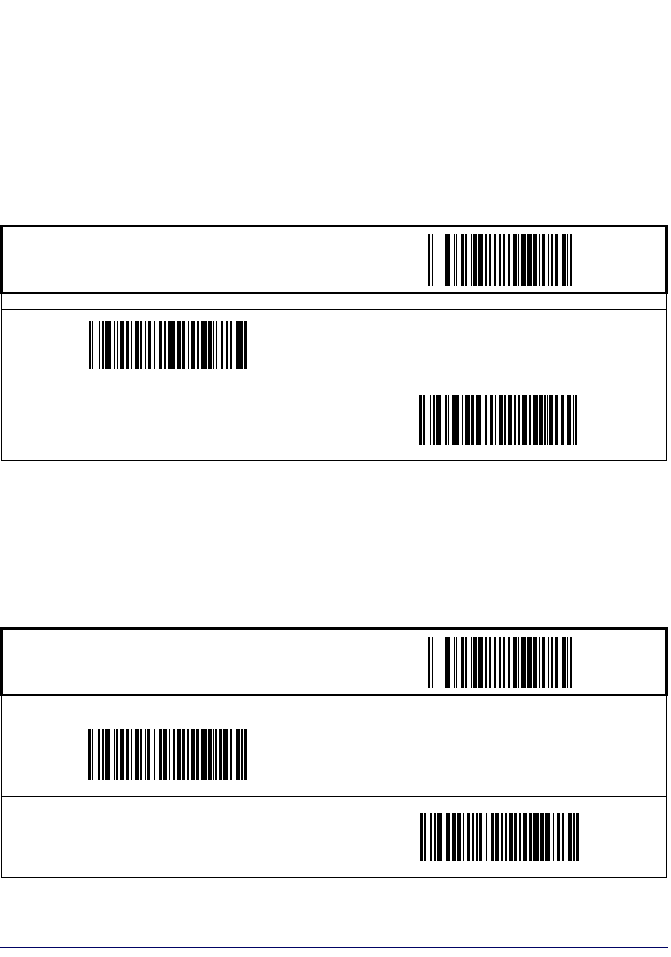
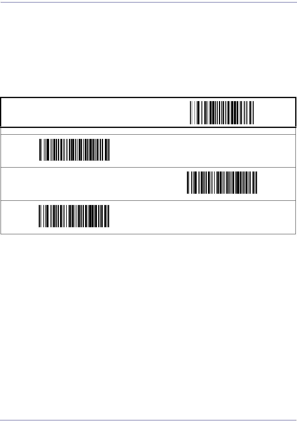
Sleep Mode
This feature specifies the amount of time with no barcode reads before the scanner enters sleep mode.
START / END
PROGRAMMING BARCODES
15 Seconds
30 Seconds
1 Minute
2 Minutes
3 Minutes
4 Minutes
5 Minutes

General Features
2-6
Magellan
®
1000i
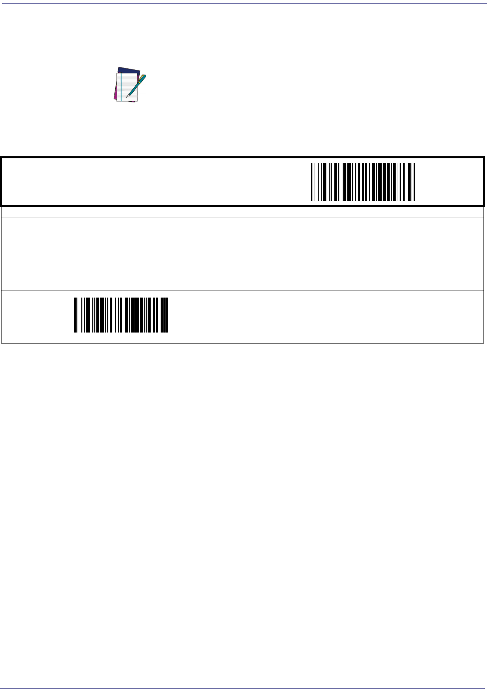
LED and Beeper Indicators
Power On Alert
Disables or enables the indication (a single beep) that the scanner has finished all its power up
tests and is now ready for operation.
START / END
PROGRAMMING BARCODES
Disable
Enable
DEFAULT
LED and Beeper Indicators
Product Reference Guide
2-7
Good Read: When to Indicate
This feature specifies when the scanner will provide indication (beep and/or flash its green LED)
upon successfully reading a barcode. Choices are:
• Good Read = Indicate after decode
• Good Read = Indicate after transmit
• Good Read = Indicate after CTS goes inactive, then active
NOTE
This option (Indicate after CTS goes inactive, then
active), which uses CTS, is only valid for RS-232 inter-
faces.
START / END
PROGRAMMING BARCODES
After Decode
DEFAULT
After Transmit
After CTS goes inactive, then active
³
General Features
2-8
Magellan
®
1000i
Good Read Beep Control
This feature enables/disables the scanner’s ability to beep upon a successful decode of a barcode.
Good Read Beep Frequency
Adjusts the good read beep to sound at a selectable low, medium or high frequency, selectable
from the list below. (Controls the beeper’s pitch/tone.)
START / END
PROGRAMMING BARCODES
Disable
Enable
DEFAULT
START / END
PROGRAMMING BARCODES
Low
Medium
DEFAULT
High
³ 001402
LED and Beeper Indicators
Product Reference Guide
2-9
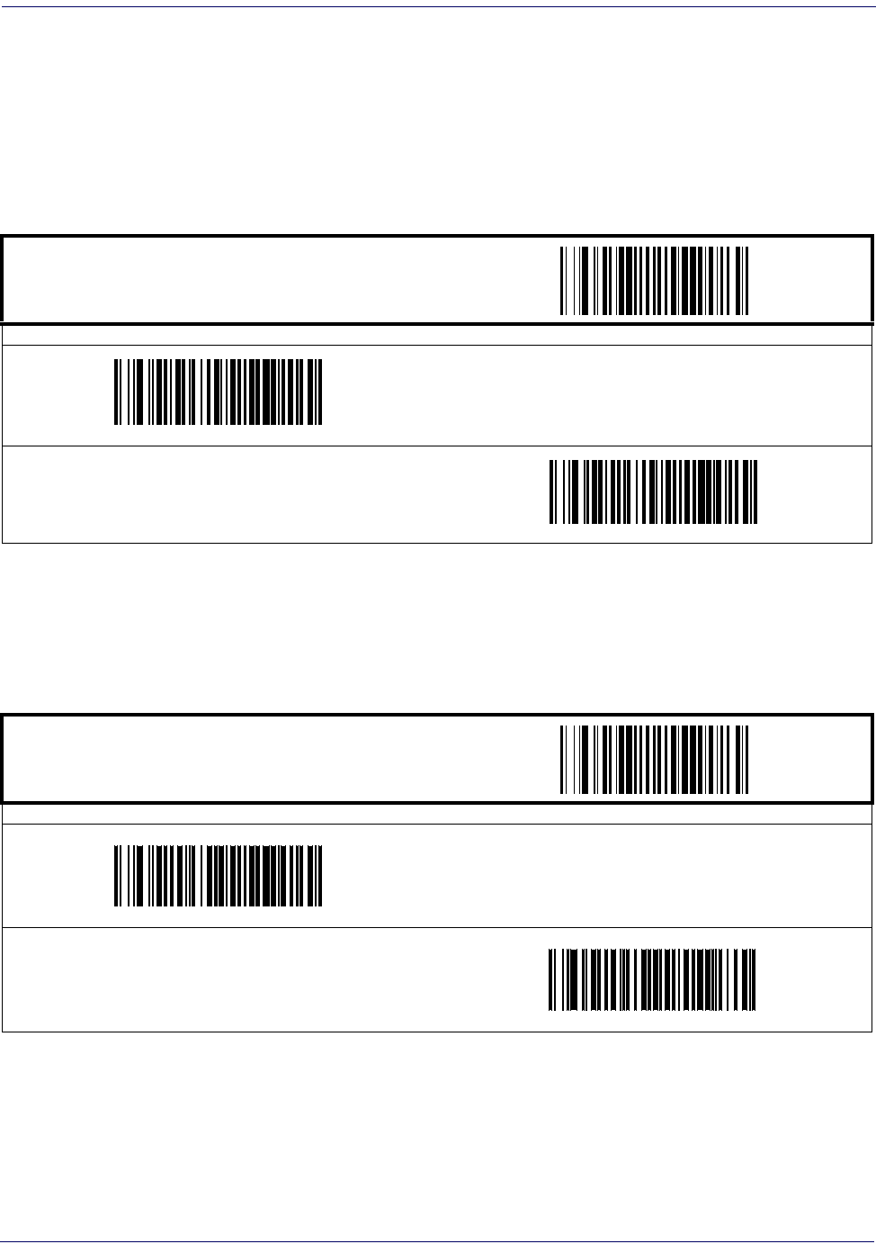
Good Read Beep Length
Specifies the duration of a good read beep.
START / END
PROGRAMMING BARCODES
60msec
80msec
DEFAULT
100msec
120msec
140msec
160msec
180msec
200msec
General Features
2-10
Magellan
®
1000i
Good Read Beep Volume
Selects the beeper volume (loudness) upon a good read beep. There are three selectable volume
levels.
START / END
PROGRAMMING BARCODES
Low
Medium
High
DEFAULT
Scanning Features
Product Reference Guide
2-11
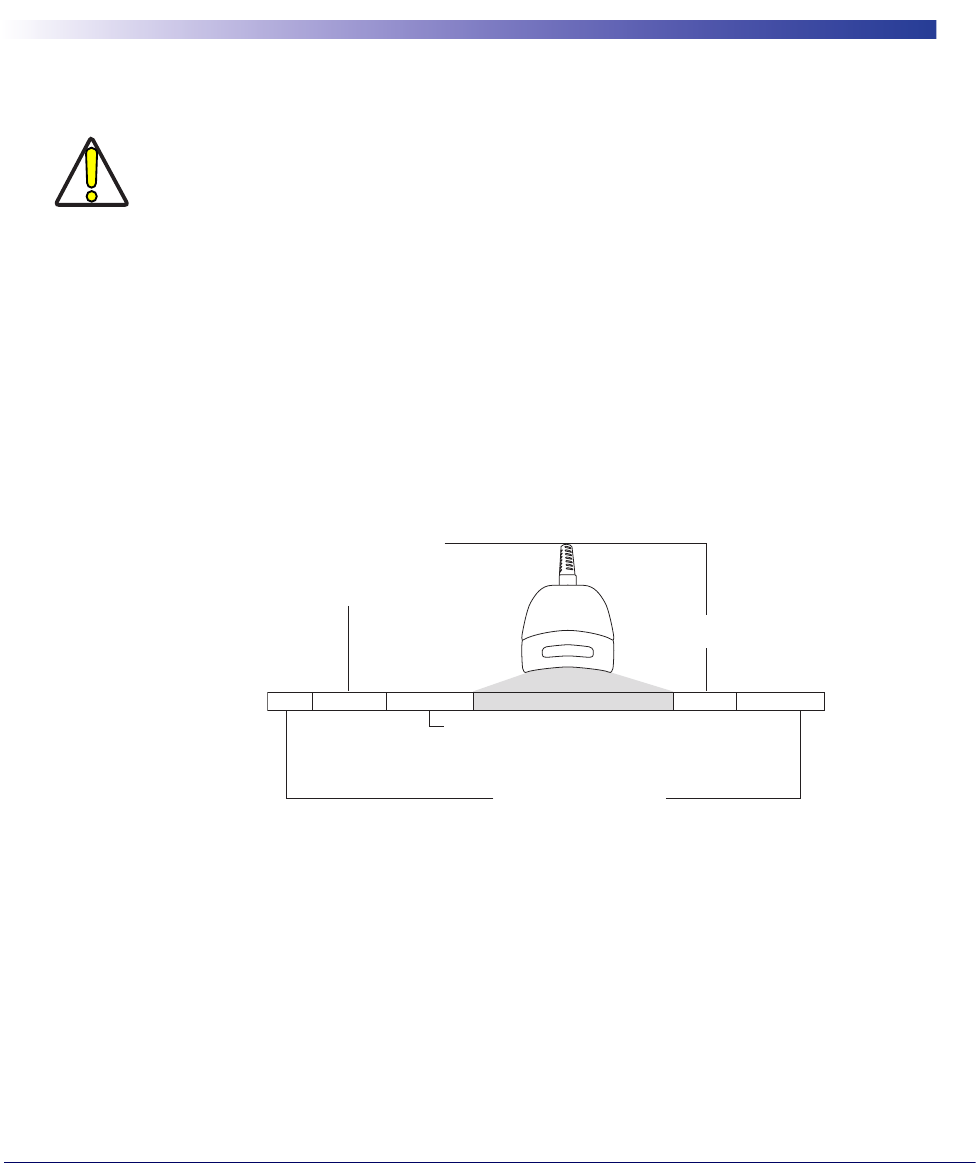
Scanning Features
Targeted Scanning Mode
Upon pressing the button, the scanner will project an aiming pattern to assist in centering over
the barcode. Scanning then takes place as soon as the button is released.
Configuration options for Targeted Scanning Mode are:
• Target Mode Active Time
•Target Mode Linger Time
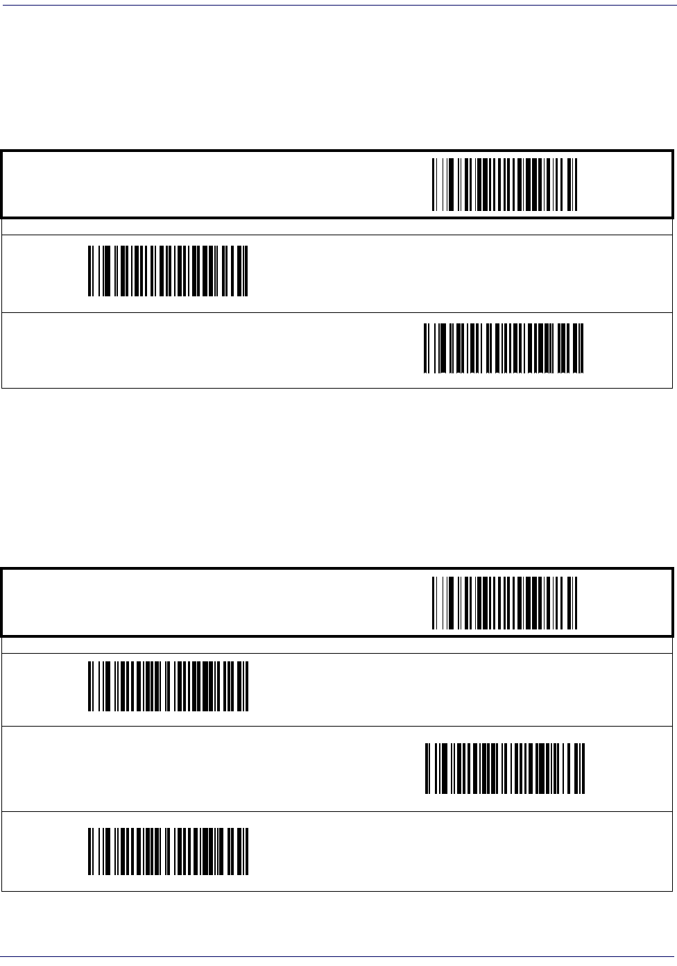
Target Mode Active Time
Specifies the time duration the scanner attempts to decode labels while in the targeted mode of
operation.
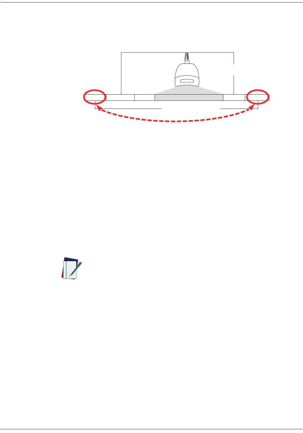
NOTE
When add-ons are enabled and a barcode is being
read while in Targeted Mode, position the pointer
at or near the end of the base label to ensure the
scanner will read both the base and add-on label.
Targeted Scanning Mode will read barcodes in any
orientation.
The scanner will return to full pattern Omni-direc-
tional Mode after Target Mode Active Time has
elapsed.
START / END
PROGRAMMING BARCODES
Extra Short Duration
Short Duration
Medium Duration
DEFAULT
Long Duration
General Features
2-12
Magellan
®
1000i
Target Mode Linger Time
Specifies the time duration the scanner remains in the targeted mode of operation after reading
a barcode before reverting to Omni-directional Mode.
START / END
PROGRAMMING BARCODES
Short Duration
Medium Duration
DEFAULT
Long Duration
Scanning Features
Product Reference Guide
2-13
Wake Up Intensity
This feature indicates the percentage of ambient light change which will trigger the scanner to
wake up from Sleep Mode. Lower settings provide greater sensitivity. The seelectable range for
this setting is 5% to 15%.
START / END
PROGRAMMING BARCODES
5%
6%
7%
8%
9%
10%
DEFAULT
11%
12%


Product Reference Guide
3-1
Chapter 3
Interface Related Features
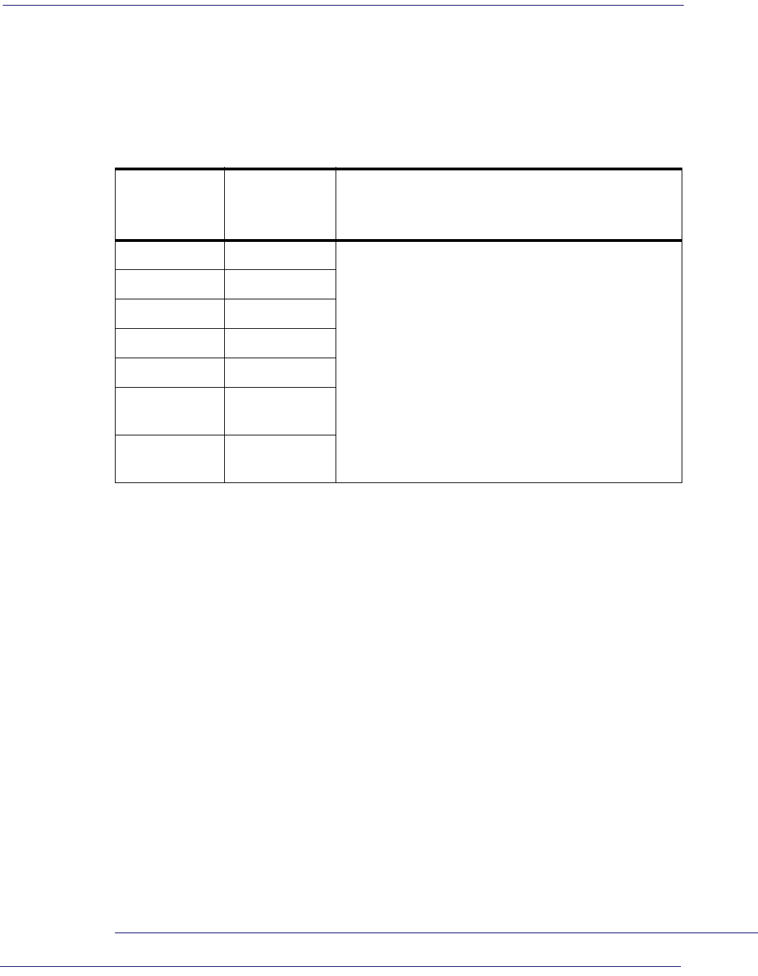
At the time of this writing, the Scanner supports the interfaces listed in Ta b l e 3 - 1 . Select the
desired interface type from the table, then reference the page number given for the customizable
features section associated with each interface. See Ta b l e 3 - 2 for a description of each Keyboard
Wedge interface type (A through Y as listed).
Table 3-1. Interfaces Supported
RS-232 Page Keyboard Wedge Page
RS-232 Standard 3-9 Keyboard Wedge Ha
RS-232 Wincor-Nixdorf 3-9 Keyboard Wedge Ia3-30
IBM Keyboard Wedge Ja3-30
IBM 4683 Port 5B 3-24 Keyboard Wedge Ka3-30
IBM 4683 Port 9B 3-24 Keyboard Wedge La3-30
IBM 4683 Port 17 3-24 Keyboard Wedge Ma3-30
USB Keyboard Wedge Na3-30
USB-OEM 3-24 Keyboard Wedge Na3-30
USB Keyboard 3-24 Keyboard Wedge Oa3-30
USB COM 3-36 Keyboard Wedge Pa3-30
Wand Emulation Keyboard Wedge Qa3-30
Wand Emulation 3-26 Keyboard Wedge Ra3-30
Keyboard Wedge 3-30 Keyboard Wedge Sa3-30
Keyboard Wedge Aa
a. Consult Ta b le for more information regarding keyboard interface types.
3-30 Keyboard Wedge Ta3-30
Keyboard Wedge Ba3-30 Keyboard Wedge Ua3-30
Keyboard Wedge Ca3-30 Keyboard Wedge Va3-30
Keyboard Wedge Da3-30 Keyboard Wedge Wa3-30
Keyboard Wedge Ea3-30 Keyboard Wedge Xa3-30
Keyboard Wedge Fa3-30 Keyboard Wedge Ya3-30
Keyboard Wedge Ga3-30
NOTE
The correct interface cable is included for the scanner
interface type you ordered.

Interface Related Features
3-2 Magellan
®
1000i
Table 3-2. Keyboard Wedge Interface Reference
I/F Type PCs Supported
A PC/XT w/Alternate Key Encoding
BAT, PS/2 25-286, 30-286, 50, 50Z, 60, 70, 80, 90 & 95 w/Alternate Key
Encoding
C PS/2 25 and 30 w/Alternate Key Encoding
D PC/XT w/Standard Key Encoding
EAT, PS/2 25-286, 30-286, 50, 50Z, 60, 70, 80, 90 & 95 w/Standard Key
Encoding
F PS/2 25 and 30 w/Standard Key Encoding
G IBM 3xxx w/122 keyboard
H IBM 3xxx w/102 keyboard
I PS/55 5530T w/104 keyboard
J NEC 9801
K WYSE 30/30+ WY-30 Keyboard 83 Keys
L
WYSE 60/85/99 GT/150/160/285 Style IBM Enhanced PC, 520/520ES
Style IBM Enhanced PC FR
WYSE 55/65/65 ES/120/185/325 Style IBM Enhanced PC
M
WYSE 60/85/99 GT/150/160/285 ANSI Keyboard 105 Keys, 520/520 ES
ANSI Keyboard 105 Keys
WYSE 55/65/65 ES/120/185/325 ANSI Keyboard 105 Keys
NWYSE 60/85/99 GT/150/160/285 ASCII Kbd, 520/520 ES ASCII Kbd
WYSE 55/65/65 ES/120/185/325 ASCII Keyboard
O
WYSE 60/85/99 GT/150/160/285 ANSI W285 Keyboard 105 Keys, 520/
520 ES ANSI W285 Keyboard 105 Keys
WYSE 55/65/65 ES/120/185/325 ANSI W285 Keyboard 105 Keys
P WYSE WINTERM 3320 SE
QIBM 3153
IBM 316X, 3179/3180/319X/3270
R IBM 3151/3152-010, 347X/348X
S DIGITAL VT 220/320/330/340/350/382
T DIGITAL VT420
U DIGITAL VT 510/520 IBM ANSI Style Keyboard
V DIGITAL VT 510/520 IBM PC Style Keyboard
W SUN SPARC 5/10
X SUN 420/440, ITX
Y WYSE 370/355 Style Enhanced IBM PC
NOTE
Reference Appendix E, Keyboard Function Key Map-
pings for more information about keyboards.
Interface Selection
Product Reference Guide
3-3
Interface Selection
START / END
PROGRAMMING BARCODES
RS-232 Standard
RS-232 Wincor-Nixdorf
IBM 4683 Port 5B
IBM 4683 Port 9B
IBM 4683 Port 17
USB-OEM
USB Keyboard
Wand Emulation
USB COM


Interface Features
Product Reference Guide
3-7
Interface Features
Obey/Ignore Host Commands
When set to ignore host commands, the scanner will ignore all host commands except for the
minimum set necessary to keep the interface active and transmit labels For normal operation of
the interface, select Obey Host Commands.
START / END
PROGRAMMING BARCODES
Obey Host Commands
DEFAULT
Ignore Host Commands
Interface Related Features
3-8 Magellan
®
1000i
Interface Features — cont.
Host Transmission Buffers
Specifies the number of host transmission(s) that may be buffered. By buffering data from a bar-
code, the scanner can continue to read a new barcode while the old one is being transmitted to
the host. Selecting BUFFERS = 1 means that the first barcode must be transmitted before a new
one can be read. A selection of BUFFERS = 2 means that a new barcode can be read while data
from the first barcode is transmitted.
When a DISABLE SCANNER command is received from the host, the scanner will continue to
transmit all data that is buffered.
START / END
PROGRAMMING BARCODES
Host Transmission Buffers = 1
Host Transmission Buffers = 2
DEFAULT
Interface Features
Product Reference Guide
3-9
RS-232 Interface Features
START / END
PROGRAMMING BARCODES
1200 Baud
2400 Baud
4800 Baud
9600 Baud
DEFAULT
19200 Baud
38400 Baud
57600 Baud
115200 Baud
³

Interface Features
Product Reference Guide
3-11
RS-232 Interface Features — cont.
Hardware Flow Control
Disable Hardware Control—
The scanner transmits to the host regardless of any activity on
the CTS line.
Enable CTS Flow Control—
The CTS signal controls transmission of data to the host.
Enable CTS Scan Control—
The CTS line must be active for the scanner to read and trans-
mit data. While the CTS line is inactive, the scanner remains in a host-disabled state; following
a successful label transmission, the CTS signal must transition to inactive and then to active to
enable scanning for the next label.
START / END
PROGRAMMING BARCODES
Disable Hardware Control
DEFAULT
Enable CTS Flow Control
Enable CTS Scan Control
Interface Related Features
3-12 Magellan
®
1000i
RS-232 Interface Features — cont.
Intercharacter Delay
This delay is inserted after each data character transmitted. If the transmission speed is too high,
the system may not be able to receive all characters. You may need to adjust the delay to make
the system work properly.
START / END
PROGRAMMING BARCODES
Inter-Char Delay = No Delay
DEFAULT
Interchar Delay = 10 msec
Interchar Delay = 20 msec
Interchar Delay = 30 msec
Interchar Delay = 40 msec
Interchar Delay = 50 msec
Interchar Delay = 60 msec
Interchar Delay = 70 msec
Interface Features
Product Reference Guide
3-13
Intercharacter Delay — cont.
Software Flow Control
Disables/Enables software control using XON/XOFF characters.
START / END
PROGRAMMING BARCODES
Interchar Delay = 80 msec
Interchar Delay = 90 msec
START / END
PROGRAMMING BARCODES
Disable Software Flow Control
DEFAULT
Enable Software Flow Control
Interface Related Features
3-14 Magellan
®
1000i
RS-232 Interface Features — cont.
Host Echo
When enabled, this feature passes all data through the scanner to the host as it comes in. This
feature is used for applications where “daisy chaining” of RS-232 devices onto the same cable is
necessary. If, for example, one of the devices in the chain is a terminal where someone is entering
data while another person is simultaneously scanning a barcode requiring transmission to the
host, the scanner will wait for the RS-232 channel to be quiet for a specified period of time (set
via RS-232 Host Echo Quiet Interval). The scanner can be set to observe this delay before sending its
data in order to avoid RS-232 transmission conflicts.
START / END
PROGRAMMING BARCODES
Disable Host Echo
DEFAULT
Enable Host Echo
Interface Features
Product Reference Guide
3-15
RS-232 Interface Features — cont.
Host Echo Quiet Interval
This setting specifies the time interval of RS-232 channel inactivity which must transpire before
the scanner will break the host echo loop to transmit the barcode data that has just been scanned
to the host.
START / END
PROGRAMMING BARCODES
Host Echo Quiet Interval = 0msec
Host Echo Quiet Interval = 10msec
DEFAULT
Host Echo Quiet Interval = 20msec
Host Echo Quiet Interval = 30msec
Host Echo Quiet Interval = 40msec
Host Echo Quiet Interval = 50msec
Host Echo Quiet Interval = 60msec
Host Echo Quiet Interval = 70msec
³06 006
Interface Related Features
3-16 Magellan
®
1000i
Host Echo Quiet Interval — cont.
Signal Voltage: Normal/TTL
Specifies whether the RS-232 interface provides TTL levels on the output pins TxD and RTS.
START / END
PROGRAMMING BARCODES
Host Echo Quiet Interval = 80msec
Host Echo Quiet Interval = 90msec
Host Echo Quiet Interval = 100msec
START / END
PROGRAMMING BARCODES
Signal Voltage: Normal RS-232
DEFAULT
Signal Voltage: TTL
³ 028 01
Interface Features
Product Reference Guide
3-17
RS-232 Invert
Enables/disables inversion of RS-232 TXD and RXD signals.
Beep on ASCII BEL
Enables/disables ability of scanner to beep (sound a good read tone) on receiving an ASCII BEL
(07 hex).
START / END
PROGRAMMING BARCODES
Disable RS-232 Invert
DEFAULT
Enable RS-232 Invert
START / END
PROGRAMMING BARCODES
Enable Beep on ASCII BEL
DEFAULT
Disable Beep on ASCII BEL

Interface Related Features
3-18 Magellan
®
1000i
Beep on Not on File
Select for the host to beep (or not) when a not-on-file (host command) condition is detected by
the host.
START / END
PROGRAMMING BARCODES
Disable Beep on Not On File
Enable Beep on Not On File
DEFAULT
Interface Features
Product Reference Guide
3-19
ACK NAK Options
This enables/disables the ability of the scanner to support the RS-232 ACK/NAK protocol.
When configured, the scanner and/or host sends an “ACK” when it receives data properly, and
sends “NAK” when the data is in error. Selections for this option are:
•Disable
• Enable for label transmission — the scanner expects an ACK/NAK response from the host
when a label is sent
• Enable for host-command acknowledge — the scanner will respond with ACK/NAK
when the host sends a command
• Enable for label transmission and host-command acknowledge
START / END
PROGRAMMING BARCODES
Disable ACK NAK
DEFAULT
Enable ACK NAK for Transmission
Enable ACK NAK for host command acknowledge
Enable ACK NAK for transmission and host command
Interface Related Features
3-20 Magellan
®
1000i
RS-232 Interface Features — cont. — cont.
ACK Character
NAK Character
START / END
PROGRAMMING BARCODES
Sets the ACK character from the set of ASCII characters or any decimal value from 000 to 255. Pad entries of less than three digits
with zeros, as in “005”. To configure this feature, scan the “START/END” barcode above to place the unit in Programming Mode, then
the “Set ACK Character,” followed by the digits from the Alphanumeric table in Appendix C, Alpha-Numeric Pad representing your
desired character. Exit programming mode by again scanning the “START/END” barcode above.
DEFAULT SETTING FOR THIS FEATURE: 006
Set ACK Character
START / END
PROGRAMMING BARCODES
Sets the NAK character from the set of ASCII characters or any decimal value from 000 to 255. Pad entries of less than three digits
with zeros, as in “005”. To configure this feature, scan the “START/END” barcode above to place the unit in Programming Mode, then
the “Set NAK Character,” followed by the digits from the Alphanumeric table in Appendix C, Alpha-Numeric Pad representing your
desired character. Exit programming mode by again scanning the “START/END” barcode above.
DEFAULT SETTING FOR THIS FEATURE: 021
Set NAK Character
Interface Features
Product Reference Guide
3-21
RS-232 Interface Features — cont.
Retry on ACK NAK Timeout
Enables/disables retry after the configurable ACK NAK Timeout Value (set in the following fea-
ture) has expired.
ACK NAK Timeout Value
START / END
PROGRAMMING BARCODES
Disable Retry on ACK NAK Timeout
Enable Retry on ACK NAK Timeout
DEFAULT
START / END
PROGRAMMING BARCODES
This item specifies the time the scanner will wait for an ACK character from the host following a label transmission.
000 = Infinite timeout
001 - 075 = Timeout in 200-millisecond increments
To configure this feature, scan the “START/END” barcode above to place the unit in Programming Mode, then the “Set ACK NAK
Timeout Value,” followed by the three digits (zero padded) from the Alphanumeric table in Appendix C, Alpha-Numeric Pad repre-
senting your desired value. Exit programming mode by again scanning the “START/END” barcode above.
DEFAULT SETTING FOR THIS FEATURE: 001 (200 msec)
Set ACK NAK Timeout Value
Interface Related Features
3-22 Magellan
®
1000i
RS-232 Interface Features — cont.
ACK NAK Retry Count
START / END
PROGRAMMING BARCODES
This feature sets the number of times for the scanner to retry a label transmission under a retry condition.
000 = No retry
001 - 254 = Retry for the specified number of times
255 = Retry forever
To configure this feature, scan the “START/END” barcode above to place the unit in Programming Mode, then the “Set ACK NAK
Retry Count,” followed by the three digits (zero padded) from the Alphanumeric table in Appendix C, Alpha-Numeric Pad repre-
senting your desired retry count. Exit programming mode by again scanning the “START/END” barcode above
DEFAULT SETTING FOR THIS FEATURE: 003
Set ACK NAK Timeout Value
Interface Features
Product Reference Guide
3-23
RS-232 Interface Features — cont.
ACK NAK Error Handling
This item specifies the method the scanner will use to handle errors detected while waiting to
receive the ACK character from the host. Errors include unrecognized host commands and com-
munication errors such as parity or framing errors. Choices are:
00 = Ignore errors detected (recommended setting)
01 = Process error as valid ACK character (risk of lost label data)
02 = Process error as valid NAK character (risk of duplicate label data)
START / END
PROGRAMMING BARCODES
Ignore Errors Detected
DEFAULT
Process error as valid ACK character
Process error as valid NAK character
Interface Related Features
3-24 Magellan
®
1000i
RS-232 Interface Features — cont.
Transmission Failure Indication
Enables/disables bad-label indication upon transmission failure.
USB-OEM Interface Features
USB-OEM Device usage
The USB-OEM protocol allows for the scanner to be identified as one of two different types of
barcode scanners. Depending on what other scanners you may already have connected to a
USB-OEM POS, you may need to change this setting to enable all devices to communicate.
Options are:
• Table Top Scanner
• Handheld Scanner
START / END
PROGRAMMING BARCODES
Disable Transmission Error Indication
Enable Transmission Error Indication
DEFAULT
START / END
PROGRAMMING BARCODES
Configure as Table Top Scanner
DEFAULT
Configure as Handheld Scanner
Interface Features
Product Reference Guide
3-25
IBM
IBM Transmit Labels in Code 39 Format
This feature enables/disables scanner's ability to set a symbology identifier for a specified label to
Code 39 before transmitting that label data to an IBM host. This applies to: Code 128,
Codabar and Code 93 for USB-OEM; Code 128, Codabar and Code 93 for IBM Port 5B; and
Codabar and Code 93 for IBM Port 9B.
START / END
PROGRAMMING BARCODES
Disable Convert to Code 39
DEFAULT
Enable Convert to Code 39

Interface Related Features
3-26 Magellan
®
1000i
Wand Emulation
Supported Symbologies
The Wand Emulation interface will transmit barcode data as a wand device would. This inter-
face will transmit the following barcode symbologies:
•UPC/EAN
• UPC/EAN with addons
•Code 39
• Full ASCII Code 39
• Interleaved 2 of 5
•Codabar
•Code 128
Pharmacode 39 is transmitted as Code 39. All other barcode symbology types read by the scan-
ner will be transmitted as Code 128.
Wand Emulation Barcode Format
The following format settings are required for the wand emulation interface. These settings have
been pre-configured at the factory for Wand Emulation scanners.
• UPC-A barcodes must include all 12 digits.
• UPC-E barcodes must contain 8 digits, including a system digit, 6 data digits, and the
check digit.
• EAN-13 barcodes must have all 13 digits.
• EAN-8 barcodes must include all 8 digits.
• Code 39, Code 39 Full ASCII, and Pharmacode 39 barcodes must NOT contain start /
stop characters.
• Codabar barcodes must include the start / stop characters, presented in the ABCD format.
• Interleaved 2 of 5 barcodes must have an even number of digits.
Interface Features
Product Reference Guide
3-27
Wand Emulation — cont.
Bar/Space Polarity
Low/High — Black will be transmitted as a low voltage level (0 to +0.7V) and space as high
level (+2.4 to +5.25V).
High/Low — Black will be transmitted as a high voltage level (+2.4 to +5.25V) and space as
low level (0 to +0.7V).
Wand Idle State
This feature specifies the level of the wand output signal when idle. TTL logic levels:
High voltage level (+2.4 to +5.25V)
Low voltage level (0 to +0.7V).
START / END
PROGRAMMING BARCODES
Bar/Space = Low/High
Bar/Space = High/Low
DEFAULT
START / END
PROGRAMMING BARCODES
Wand Idle State = Low
DEFAULT
Wand Idle State = High
Interface Related Features
3-28 Magellan
®
1000i
Wand Emulation — cont.
Signal Speed
The speed of the transmission can be set. This selects the width of the minimum narrow bar.
330 microseconds
660 microseconds
Transmit Trailing Noise
The transmission of noise pulses after the label may be enabled or disabled.
START / END
PROGRAMMING BARCODES
Signal Speed = 330mS
Signal Speed = 660mS
DEFAULT
START / END
PROGRAMMING BARCODES
Disable Trailing Noise
Enable Trailing Noise
DEFAULT
Interface Features
Product Reference Guide
3-29
Wand Emulation — cont.
Transmit Leading Noise
The transmission of noise pulses before the barcode may be enabled or disabled.
Symbology Conversion
Wand Emulation can convert all barcodes to a single symbology. Choices are:
No Conversion
Convert to Code 39
Convert to Code 128
START / END
PROGRAMMING BARCODES
Disable Leading Noise
Enable Leading Noise
DEFAULT
START / END
PROGRAMMING BARCODES
No Symbology Conversion
DEFAULT
Convert to C39
Convert to C128
Interface Related Features
3-30 Magellan
®
1000i
Keyboard Wedge
and
USB Keyboard
As a keyboard interface, the scanner supports most popular PCs and IBM terminals. The instal-
lation of the wedge is a fairly simple process that doesn’t require any changes of software or hard-
ware.
Keyboard Layout
The Keyboard Layout option supports many countries. For details about Keyboard Layout,
please refer to your operating system manual.
NOTE
All of the options in this section apply to the Key-
board Wedge, however, only some apply to USB Key-
board.
START / END
PROGRAMMING BARCODES
USA
DEFAULT
Belgium
Britain
Denmark
France
Germany


Interface Features
Product Reference Guide
3-33
Keyboard Wedge — cont.
Power-On Simulation
All PCs check the keyboard status during the power-on Selftest. It is recommended that you
enable this function if you are working without a keyboard installation. It simulates keyboard
timing and passes the keyboard status to the PC during power-on.
NOTE
This feature does not apply to the USB Keyboard
interface.
START / END
PROGRAMMING BARCODES
Disable Power-on Simulation
DEFAULT
Enable Power-on Simulation
³ 028900
Interface Related Features
3-34 Magellan
®
1000i
Control Characters
Specifies how the scanner transmits ASCII control characters to the host. Choices are:
• Disable Control Characters
• Enable transmission of control characters to host
• Send characters between 00H and 1FH according to a special function-key mapping
table. (This is used to send keys that are not in the normal ASCII set; a unique set is pro-
vided for each available scancode set. Reference Appendix E, Keyboard Function Key Map-
pings.)
START / END
PROGRAMMING BARCODES
Disable Control Characters
DEFAULT
Enable Transmission of Control Characters
Enable Function Key Mapping
Interface Features
Product Reference Guide
3-35
Keyboard Wedge — cont.
Wedge Quiet Interval
Quiet Interval is the amount of time to look for keyboard activity before the scanner breaks the
keyboard connection in order to transmit data to the host.
NOTE
This feature does not apply to the USB Keyboard
interface.
START / END
PROGRAMMING BARCODES
Selectable from 000 (no interval) to 255 in 10 msec increments. To configure this feature, scan the “START/END” barcode above to
place the unit in Programming Mode, then the Set Wedge Quiet Interval barcode followed by the three digits (zero padded) from
the Alphanumeric table in Appendix C, Alpha-Numeric Pad representing your desired length. Exit programming mode by again
scanning the “START/END” barcode above.
DEFAULT SETTING FOR THIS FEATURE:
010 (100 msec)
Set Wedge Quiet Interval
Interface Related Features
3-36 Magellan
®
1000i
Keyboard Wedge — cont.
Intercharacter Delay
USB COM Interface Set-up
This interface uses the Microsoft Windows USB COM driver. Before plugging your reader into
the host PC, please ensure you have already copied the DLS_EUG_CDC_ACM.inf file pro-
vided by Datalogic to your PC and the reader’s interface is set to USB COM.
1. When you first plug the reader into the PC, Windows will bring up the “Found New
Hardware Wizard.” Select “Install from a list” and click on “Next.”
2. Click on “Include this location in the search” and enter the path where the file
DLS_EUG_CDC_ACM.inf file is stored. Click on “Next.”
3. If a message appears that says the software has not passed Windows logo testing, press
“Continue” anyway.
4. Click on “Finish.”
Once the install is complete, reboot the PC.
NOTE
This feature does not apply to the USB Keyboard interface.
START / END
PROGRAMMING BARCODES
One-half of the delay specified below is inserted between scancodes within each character. If the transmission speed is too high, the
system may not be able to receive all characters. You may need to adjust the delay to make the system work properly. Selectable
from 000 to 255 in 10msec increments.
To configure this feature, scan the “START/END” barcode above to place the unit in Programming Mode, then the “Set Intercharacter
Delay,” followed by the three digits (zero padded) from the Alphanumeric table in Appendix C, Alpha-Numeric Pad representing
your desired length. Exit programming mode by again scanning the “START/END” barcode above/
DEFAULT SETTING FOR THIS FEATURE:
000 (No Delay)
Set Intercharacter Delay
Product Reference Guide
4-1
Chapter 4
Data Editing
Data Editing Overview
When a barcode is scanned, additional information can be sent to the host computer along with
the barcode data. This combination of barcode data and supplementary user-defined data is
called a “message string.” The features in this chapter can be used to build specific user-defined
data into a message string.
There are several types of selectable data characters that can be sent before and after scanned
data. You can specify if they should be sent with all symbologies, or only with specific symbolo-
gies. Figure 4-1 shows the available elements you can add to a message string:
Figure 4-1. Breakdown of a Message String
Please Keep In Mind...
• Modifying a message string is not a mandatory requirement. Data editing is sophisticated
feature allowing highly customizable output for advanced users. Factory default settings
for data editing is typically set to NONE.
• A prefix or suffix may be applied (reference the Symbologies chapter for these settings)
across all symbologies (set via the Global features in this chapter).
• You can add any character from the ASCII Chart (from 00-FF) on the inside back cover of
this manual as a prefix, suffix or Label ID.
• Enter prefixes and suffixes in the order in which you want them to appear on the output.
CAUTION
It is not recommended to use these features with IBM
or Wand Emulation interfaces.
Prefix SuffixAIM IDLabel ID Label IDBar Code Data
00 - 20 Characters (ASCII)
Label ID Transmission:
Enable this option to
transmit the Label ID you
configure for the scanned
symbology.
AIM ID: This function is used to identify and display the
common label identifier for its symbology. When enabled,
this ID code will be transmitted before the scanned bar
code data.
OR...
Data Editing
4-2 Magellan
®
1000i
Global Prefix/Suffix
Up to 20 ASCII characters may be added as a prefix (in a position before the barcode data) and/
or as a suffix (in a position following the barcode data) as indicated in Figure 4-2.
Figure 4-2. Prefix and Suffix Positions
Example: Setting a Prefix
In this example, we’ll set a prefix for all symbologies.
1. Determine which ASCII character(s) are to be added to scanned barcode data. In this
example, we’ll add a dollar sign (‘$’) as a prefix.
2. Scan the START barcode.
3. Scan the SET PREFIX barcode.
4. Reference the ASCII Chart on the inside back cover of this manual, to find the hex value
assigned to the desired character. The corresponding hex number for the ‘$’ character is
24. To enter this selection code, scan the ‘2’ and ‘4’ barcodes from Appendix C, Alpha-
Numeric Pad.
5. Scan the END barcode to exit Programming Mode.
6. The resulting message string would appear as follows:
Scanned barcode data:12345
Resulting message string output: $12345
NOTE
If less than the expected string of 20 characters are
selected, scan the END barcode twice to accept the
selections and exit Programming Mode.
Prefix SuffixAIM IDLabel ID Label IDBar Code Data
00 - 20 Characters (ASCII)
AND
OR
OR...
Global Prefix/Suffix
Product Reference Guide
4-3
Global Prefix/Suffix — cont.
START / END
PROGRAMMING BARCODES
Sets up to 20 characters each from the set of ASCII characters or any hex value from 0 to FF. To configure this feature, scan the
“START/END” barcode above to place the unit in Programming Mode, then the “Set Prefix” or “Set Suffix,” followed by the digits from
the Alphanumeric table in Appendix C, Alpha-Numeric Pad representing your desired character(s). Reference the section,
"Example: Setting a Prefix", for more information. Exit programming mode by scanning the “START/END” barcode again (scan
“START/END” twice if less than 20 characters have been selected).
DEFAULT SETTING PREFIX: 00 (None)
DEFAULT SETTING SUFFIX: 0D (CR)
Set Prefix
Set Suffix
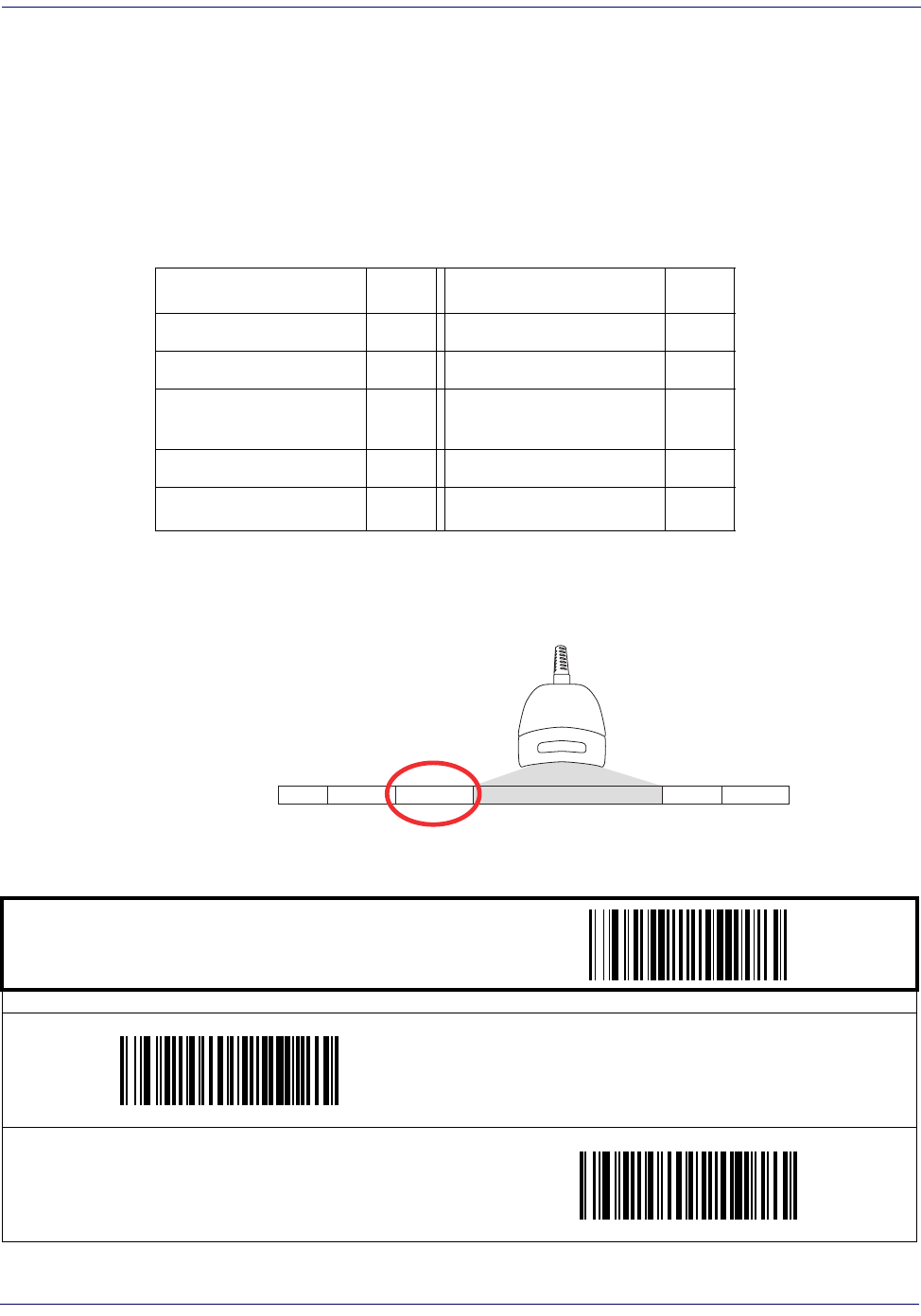
Data Editing
4-4 Magellan
®
1000i
AIM ID
AIM (Automatic Identification Manufacturers) label identifiers are assigned from a globally
standardized list — as opposed to custom label ID characters you select yourself — and can be
included with scanned barcode data. AIM label identifiers consist of three characters as follows:
• A close brace character (ASCII ‘]’), followed by...
• A code character (see the table below), followed by...
• A modifier character (the modifier character is symbol dependent)
Figure 4-3. AIM ID
SYMBOLOGY CHAR SYMBOLOGY CHAR
UPC/EAN E Code 128/EAN 128 C
Code 39 A MSI/Plessey M
Codabar F RSS (GS1 Omnidirectional,
GS1 Expanded) e
Interleaved 2 of 5 I Standard 2 of 5 S
Code 93 G ISBN Xa
a. ISBN (X with a 0 modifier character)
Prefix SuffixLabel ID Label IDBar Code DataAIM ID
START / END
PROGRAMMING BARCODES
Disable AIM ID
DEFAULT
Enable AIM ID
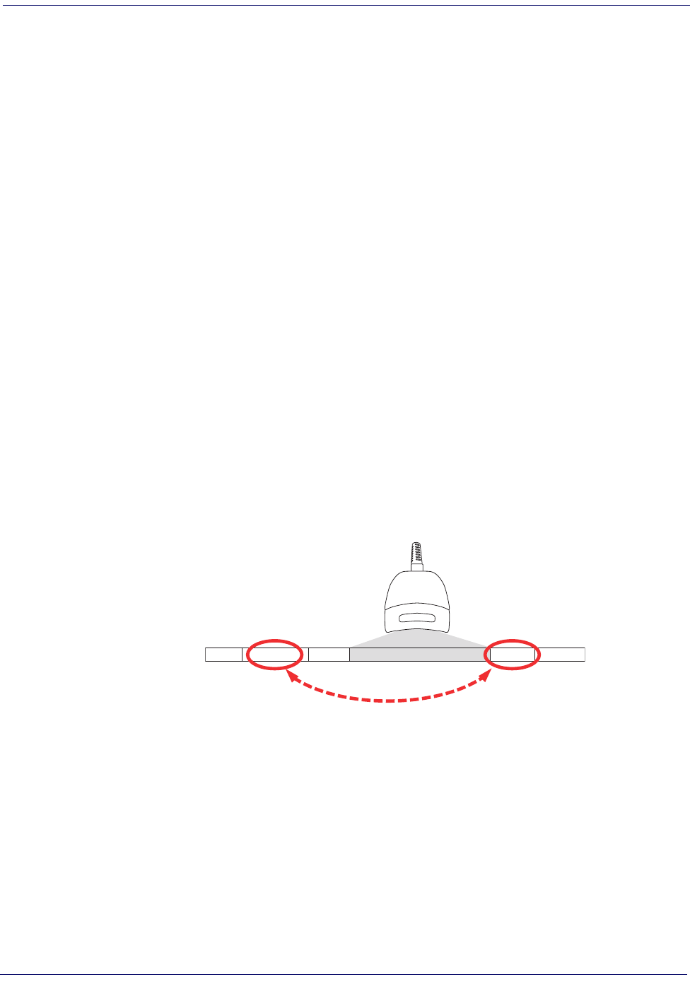
Label ID
Product Reference Guide
4-5
Label ID
A Label ID is a customizable code of up to two ASCII characters (00-FF), used to identify a bar-
code (symbology) type. See Appendix D, Default Settings, for a listing for common symbologies. It
can be appended previous to or following the transmitted barcode data depending upon how
this option is enabled. This feature provides options for configuring custom Label IDs individu-
ally per symbology. If you wish to program the scanner to always include an industry standard
label identifier for ALL symbology types, see the previous feature, AIM ID.
To configure a Label ID:
1. Scan the START barcode.
2. Select Label ID position as either BEFORE or AFTER by scanning the appropriate bar-
code.
3. Scan a barcode to select the symbology for which you wish to configure a custom Label
ID.
4. Determine the desired character(s) (you may choose either one or two) which will repre-
sent the Label ID for the selected symbology. Next, turn to the ASCII Chart on the inside
back cover of this manual and find the equivalent hex digits associated with your choice of
Label ID. For example, if you wish to select an equal sign (=) as a Label ID, the chart indi-
cates its associated hex characters as 3D.
5. Turn to Appendix C, Alpha-Numeric Pad and scan the barcodes representing the hex charac-
ters determined in the previous step. For the example given, the characters ‘3’ and ‘D’
would be scanned.
6. Scan the END barcode to exit programming mode.
Figure 4-4. Label ID Position Options
OR
Prefix SuffixLabel ID Label IDBar Code DataAim ID
Data Editing
4-6 Magellan
®
1000i
Label ID — cont.
START / END
PROGRAMMING BARCODES
Label ID Transmission: Disable
Label ID Position: Before Barcode Data
DEFAULT
Label ID Position: After Barcode Data
Set UPC-A Label ID Character(s)
DEFAULT SETTING FOR THIS FEATURE: A (41 hex)
DEFAULT SETTING FOR THIS FEATURE: A (41 hex)
Set UPC-A w/P2 Addon Label ID Character(s)
Set UPC-A w/P5 Addon Label ID Character(s)
DEFAULT SETTING FOR THIS FEATURE: A (41 hex)
DEFAULT SETTING FOR THIS FEATURE: A (41 hex)
Set UPC-A w/C128 Addon Label ID Character(s)
Set UPC-E Label ID Character(s)
DEFAULT SETTING FOR THIS FEATURE: E (45 hex)
Label ID
Product Reference Guide
4-7
Label ID — cont.
START / END
PROGRAMMING BARCODES
DEFAULT SETTING FOR THIS FEATURE: E (45 hex)
Set UPC-E w/P2 Addon Label ID Character(s)
Set UPC-E w/P5 Addon Label ID Character(s)
DEFAULT SETTING FOR THIS FEATURE: E (45 hex)
DEFAULT SETTING FOR THIS FEATURE: E (45 hex)
Set UPC-E w/C128 Addon Label ID Character(s)
Set EAN-8 Label ID Character(s)
DEFAULT SETTING FOR THIS FEATURE: FF (4646 hex)
DEFAULT SETTING FOR THIS FEATURE: FF (4646 hex)
Set EAN-8 w/P2 Addon Label ID Character(s)
Set EAN-8 w/P5 Addon Label ID Character(s)
DEFAULT SETTING FOR THIS FEATURE: FF (4646 hex)
DEFAULT SETTING FOR THIS FEATURE: FF (4646 hex)
Set EAN-8 w/C128 Addon Label ID Character(s)
Set EAN-13 Label ID Character(s)
DEFAULT SETTING FOR THIS FEATURE: F (46 hex)
³ 0027
Data Editing
4-8 Magellan
®
1000i
Label ID — cont.
START / END
PROGRAMMING BARCODES
DEFAULT SETTING FOR THIS FEATURE: F (46 hex)
Set EAN-13 w/P2 Addon Label ID Character(s)
Set EAN-13 w/P5 Addon Label ID Character(s)
DEFAULT SETTING FOR THIS FEATURE: F (46 hex)
DEFAULT SETTING FOR THIS FEATURE: F (46 hex)
Set EAN-13 w/C128 Addon Label ID Character(s)
Set ISBN Label ID Character(s)
DEFAULT SETTING FOR THIS FEATURE: I (49 hex)
DEFAULT SETTING FOR THIS FEATURE: IA (4941 hex)
Set IATA Label ID Character(s)
Set GTIN Label ID Character(s)
DEFAULT SETTING FOR THIS FEATURE: G (47 hex)
DEFAULT SETTING FOR THIS FEATURE: G2 (4732 hex)
Set GTIN w/P2 addon Label ID Character(s)
Set GTIN w/P5 addon Label ID Character(s)
DEFAULT SETTING FOR THIS FEATURE: G5 (4735 hex)
³ 034C
³0 61
³ 0562
Label ID
Product Reference Guide
4-9
Label ID — cont.
START / END
PROGRAMMING BARCODES
DEFAULT SETTING FOR THIS FEATURE: G8 (4738 hex)
Set GTIN w/C128 addon Label ID Character(s)
Set GS1 Omnidirectional Label ID Character(s)
DEFAULT SETTING FOR THIS FEATURE: R4 (5234 hex)
DEFAULT SETTING FOR THIS FEATURE: RX (5258 hex)
Set GS1 Expanded Label ID Character(s)
Set Code GS1 DataBar Limited Label ID Character(s)
DEFAULT SETTING FOR THIS FEATURE: * (524C0000 hex)
DEFAULT SETTING FOR THIS FEATURE: * (2A hex)
Set Code 39 Label ID Character(s)
Set Pharmacode 39 Label ID Character(s)
DEFAULT SETTING FOR THIS FEATURE: A (41 hex)
DEFAULT SETTING FOR THIS FEATURE: # (23 hex)
Set Code 128 Label ID Character(s)
Set I 2 of 5 Label ID Character(s)
DEFAULT SETTING FOR THIS FEATURE: i (69 hex)
³

Data Editing
4-10 Magellan
®
1000i
Label ID
Product Reference Guide
4-11
Label ID — cont.
START / END
PROGRAMMING BARCODES
DEFAULT SETTING FOR THIS FEATURE: % (25 hex)
Set Codabar Label ID Character(s)
Set Code 93 Label ID Character(s)
DEFAULT SETTING FOR THIS FEATURE: & (26 hex)
DEFAULT SETTING FOR THIS FEATURE: @ (40 hex)
Set Code 11 Label ID Character(s)
Set MSI/Plessey Label ID Character(s)
DEFAULT SETTING FOR THIS FEATURE: @ (40 hex)
DEFAULT SETTING FOR THIS FEATURE: s (73 hex)
Set Std 2 of 5 Label ID Character(s)
Set EAN UCC Composite Label ID Character(s)
DEFAULT SETTING FOR THIS FEATURE: 0
DEFAULT SETTING FOR THIS FEATURE: P (0x5000)a
a.
Default setting exceptions for PDF 417 Label ID are as follows: Default for RS-232 WN is ‘Q’ (0x5100). Default for USB-HID-
POS is ‘P ‘ (0x5020), or ‘P-Space’.
Set PDF 417 Label ID Character(s)
Set Datamatrix Label ID Character(s)
DEFAULT SETTING FOR THIS FEATURE: Dm (0x446D)
³ 0037
³
Data Editing
4-12 Magellan
®
1000i
Case Conversion
This feature can convert scanned barcode data to either all lower case (a through z) or all upper
case (A through Z) characters.
NOTE
Case conversion affects ONLY scanned barcode data,
and does not affect Label ID, Prefix, Suffix, or other
appended data.
START / END
PROGRAMMING BARCODES
Disable
DEFAULT
Convert to Upper Case
Convert to Lower Case

Character Conversion
Product Reference Guide
4-13
Character Conversion
Character conversion is an eight byte configuration item. The eight bytes are 4 character pairs
represented in hexadecimal ASCII values. The first character in the pair is the character that
will be converted. The second character in the pair is the character to convert to. If the charac-
ter to convert in a pair is FF, then no conversion is done.
For example, if you have the character conversion configuration item set to the following:
41423132FFFFFFFF
The first pair is 4142 or AB (41 hex is an ASCII capital A, 42 hex is an ASCII capital B) and
the second pair is 3132 or 12 (31 hex is an ASCII 1, 32 is an ASCII 2). The other two pairs
are FFFF and FFFF.
With the label, AG15TA81, it would look as follows after the character conversion:
BG25TB82.
The A characters were converted to the B character and the 1 characters were converted to the
numeral 2 character. Nothing is done with the last two character pairs, since they are all FF.
To set Character Conversion:
1. Scan the START/END barcode.
2. Scan the Character Conversion barcode.
3. Determine the desired string. Up to sixteen positions can be determined as in the above
example. Next, turn to the ASCII Chart on the inside back cover of this manual and find
the equivalent hex digits needed to fulfill the string.
4. Turn to Appendix C, Alpha-Numeric Pad and scan the barcodes representing the hex charac-
ters determined in the previous step.
5. Scan the START/END barcode to exit Programming Mode.
NOTE
If less than the expected string of 16 characters are
selected, scan the START/END barcode twice to accept
the selections and exit Programming Mode.
START / END
PROGRAMMING BARCODES
DEFAULT SETTING FOR THIS FEATURE:
FFFFFFFFFFFFFFFF hex (no conversion)
Character Conversion

Data Editing
4-14 Magellan
®
1000i
Product Reference Guide
5-1
Chapter 5
Symbologies
The scanner supports the following symbologies (barcode types). Options for each symbology
are included in this chapter.
Factory Defaults—
for the standard RS-232 interface are indicated in bold text throughout
this section. Reference Appendix D, Default Settings for default exceptions for your interface.
UPC-A
Disable/Enable UPC-A
When disabled, the scanner will not read UPC-A barcodes.
•UPC-A •Pharmacode 39
•UPC-E •Code 128
•EAN-13 •Interleaved 2 of 5
•EAN-8 •Codabar
•GS1 DataBar Omnidirectional /
Stacked Omnidirectional •Code 93
•GS1 DataBar Expanded /
Expanded Stacked •MSI/Plessey
•GS1 DataBar Limited •Standard 2 of 5
•Code 39
START / END
PROGRAMMING BARCODES
Disable UPC-A
Enable UPC-A
DEFAULT
Symbologies
5-2 Magellan
®
1000i
UPC-A — continued
Check Digit Transmission
Enable this option to transmit the check digit along with UPC-A barcode data.
Expand UPC-A to EAN-13
Expands UPC-A data to the EAN-13 data format. Selecting this feature also changes the sym-
bology ID to match those required for EAN-13.
START / END
PROGRAMMING BARCODES
Don’t Send Check Digit
Send Check Digit
DEFAULT
³
START / END
PROGRAMMING BARCODES
Don’t Expand to EAN-13
DEFAULT
Expand to EAN-13
UPC-A
Product Reference Guide
5-3
UPC-A — continued
Number System Transmission
This feature enables/disables transmission of UPC-A System Number.
UPC-A Minimum Reads
This feature specifies the minimum number of consecutive times a UPC-A label must be
decoded before it is accepted as good read.
START / END
PROGRAMMING BARCODES
Disable Number System Transmission
Enable Number System Transmission
DEFAULT
START / END
PROGRAMMING BARCODES
Minimum = 1 Read
DEFAULT
Minimum = 2 Reads
Minimum = 3 Reads
Minimum = 4 Reads
Symbologies
5-4 Magellan
®
1000i
UPC-A — continued
UPC-A In-store Minimum Reads
This feature specifies the minimum number of consecutive times an in-store printed label must
be decoded before it is accepted as good read.
START / END
PROGRAMMING BARCODES
Minimum = 1 Read
DEFAULT
Minimum = 2 Reads
Minimum = 3 Reads
Minimum = 4 Reads
UPC-E
Product Reference Guide
5-5
UPC-E
The following options apply to the UPC-E symbology.
Disable/Enable UPC-E
When disabled, the scanner will not read UPC-E barcodes.
Check Digit Transmission
Enable this option to transmit the check digit along with UPC-E barcode data.
START / END
PROGRAMMING BARCODES
Disable UPC-E
Enable UPC-E
DEFAULT
START / END
PROGRAMMING BARCODES
Don’t Send Check Digit
Send Check Digit
DEFAULT
Symbologies
5-6 Magellan
®
1000i
UPC-E — continued
Number System Digit
The Number System Digit (NSD) which is always a zero (0) in the leading position can be
optionally included (or not) with scanned barcode data.
Expand to UPC-E to UPC-A
Enables/disables expansion of UPC-E labels to UPC-A. Selecting this feature also changes the
symbology ID to match those required for UPC-A.
START / END
PROGRAMMING BARCODES
Exclude Number System Digit
DEFAULT
Include Number System Digit
³ 02 801
START / END
PROGRAMMING BARCODES
Don’t Expand UPC-E to UPC-A
DEFAULT
Expand UPC-E to UPC-A
UPC-E
Product Reference Guide
5-7
UPC-E — continued
Expand UPC-E to EAN13
Enables/disables expansion of UPC-E labels to EAN-13. Selecting this feature also changes the
symbology ID to match those required for EAN-13.
Minimum Reads
This feature specifies the minimum number of consecutive times a UPC-E label must be
decoded before it is accepted as good read.
START / END
PROGRAMMING BARCODES
Don’t Expand UPC-E to EAN-13
DEFAULT
Expand UPC-E to EAN-13
START / END
PROGRAMMING BARCODES
Minimum = 1 Read
Minimum = 2 Reads
DEFAULT
Minimum = 3 Reads
Minimum = 4 Reads
³ 00620
Symbologies
5-8 Magellan
®
1000i
GTIN
The following options apply to the GTIN label data format.
Expand UPC/EAN to GTIN
When this feature is enabled, the scanner will translate UPC/EAN labels to the 14 digit GTIN
format.
START / END
PROGRAMMING BARCODES
Don’t Expand to GTIN
DEFAULT
Expand to GTIN
EAN-13
Product Reference Guide
5-9
EAN-13
The following options apply to the EAN-13 symbology.
Disable/Enable EAN-13
When disabled, the scanner will not read EAN-13 barcodes.
Check Digit Transmission
Enable this option to transmit the check digit along with EAN-13 barcode data.
START / END
PROGRAMMING BARCODES
Disable EAN-13
Enable EAN-13
DEFAULT
START / END
PROGRAMMING BARCODES
Don’t Send Check Digit
Send Check Digit
DEFAULT
Symbologies
5-10 Magellan
®
1000i
EAN-13 — continued
EAN-13 Flag 1 Character
Enables/disables transmission of an EAN/JAN13 Flag1 character.
ISBN
When enabled, this feature truncates the leading three digits from labels that contain ISBN
(International Standard Book Number) and appends an ISBN check character to the end of the
label. These codes are used for books and magazines. Labels with ISBN codes start with "978".
Example:
Barcode data: “9789572222720”
Output: “9572222724”
START / END
PROGRAMMING BARCODES
Don’t Transmit EAN-13 Flag 1 Char
Transmit EAN-13 Flag 1 Char
DEFAULT
START / END
PROGRAMMING BARCODES
Disable ISBN
DEFAULT
Enable ISBN
EAN-13
Product Reference Guide
5-11
EAN-13 — continued
Minimum Reads
This feature specifies the minimum number of consecutive times an EAN-13 label must be
decoded before it is accepted as good read.
START / END
PROGRAMMING BARCODES
Minimum = 1 Read
DEFAULT
Minimum = 2 Reads
Minimum = 3 Reads
Minimum = 4 Reads
³ 006 0
Symbologies
5-12 Magellan
®
1000i
EAN-8
The following options apply to the EAN-8 symbology.
Disable/Enable EAN-8
When disabled, the scanner will not read EAN-8 barcodes.
Check Digit Transmission
Enable this option to transmit the check Digit along with EAN-8 barcode data.
START / END
PROGRAMMING BARCODES
Disable EAN-8
Enable EAN-8
DEFAULT
START / END
PROGRAMMING BARCODES
Don’t Send Check Digit
Send Check Digit
DEFAULT
EAN-8
Product Reference Guide
5-13
EAN-8 — continued
Expand EAN-8 to EAN-13—
Expands EAN-8 data to the EAN-13 data format. Selecting
this feature also changes the symbology ID to match those required for EAN-13.
Minimum Reads
This feature specifies the minimum number of consecutive times an EAN-8 label must be
decoded before it is accepted as good read.
START / END
PROGRAMMING BARCODES
Don’t Expand to EAN-13
DEFAULT
Expand to EAN-13
START / END
PROGRAMMING BARCODES
Minimum = 1 Read
DEFAULT
Minimum = 2 Reads
Minimum = 3 Reads
Minimum = 4 Reads
³
Symbologies
5-14 Magellan
®
1000i
Enable EAN Two-Label
Enables/disables the ability of the scanner to decode EAN two-label pairs.
START / END
PROGRAMMING BARCODES
Disable EAN Two-Label
Enable EAN Two-Label

Add-ons
Product Reference Guide
5-15
Add-ons
Add-ons (or supplemental characters) are commonly added to the end of UPC/EAN barcodes.
The scanner will read the add-ons if they are enabled and in the field of view. Three add-on
types are supported: 2-digit, 5-digit and Code 128 add-ons. Supported options are:
None—
This option directs the scanner to ignore add-on portion of a UPC/EAN barcode but
still read the main portion of the barcode.
2 Digits—
The scanner will optionally read 2-digit add-ons with the UPC/EAN label.
5 Digits—
The scanner will optionally read 5-digit add-ons with the UPC/EAN label.
Code 128 Add-on—
The scanner will optionally read Code 128 add-ons with the UPC/EAN
label.
NOTE
Contact Customer Support for
advanced programming of optional
and conditional add-ons.
Symbologies
5-16 Magellan
®
1000i
Add-ons — continued
START / END
PROGRAMMING BARCODES
Disable Optional 2-Digit Add-ons
DEFAULT
Enable Optional 2-Digit Add-ons
Disable Optional 5-Digit Add-ons
DEFAULT
Enable Optional 5-Digit Add-ons
Disable Optional Code 128 Add-ons
DEFAULT
Enable Optional Code 128 Add-ons
³ 0 1101
GS1 DataBar Omnidirectional / Stacked Omnidirectional
Product Reference Guide
5-17
GS1 DataBar Omnidirectional / Stacked Omnidirectional
The following options apply to the GS1 DataBar Omnidirectional symbology.
Disable/Enable GS1 DataBar Omnidirectional
When this feature is disabled, the scanner will not read GS1 DataBar Omnidirectional barcodes.
UCC/EAN 128 Emulation
When enabled, GS1 DataBar Omnidirectional barcodes will be translated to the UCC/EAN
128 label data format.
START / END
PROGRAMMING BARCODES
Disable GS1 DataBar Omnidirectional
DEFAULT
Enable GS1 DataBar Omnidirectional
START / END
PROGRAMMING BARCODES
Disable UCC/EAN 128 Emulation
DEFAULT
Enable UCC/EAN 128 Emulation
Symbologies
5-18 Magellan
®
1000i
GS1 DataBar Omnidirectional / Stacked Omnidirectional —
continued
Minimum Reads
This feature specifies the minimum number of consecutive times an GS1 DataBar Omnidirec-
tional label must be decoded before it is accepted as good read.
START / END
PROGRAMMING BARCODES
Minimum = 1 Read
DEFAULT
Minimum = 2 Reads
Minimum = 3 Reads
Minimum = 4 Reads
GS1 DataBar Expanded / Expanded Stacked
Product Reference Guide
5-19
GS1 DataBar Expanded / Expanded Stacked
The following options apply to the GS1 DataBar Expanded symbology.
Disable/Enable GS1 DataBar Expanded
When this feature is disabled, the scanner will not read GS1 DataBar Expanded barcodes.
GS1-128 Emulation
When enabled, GS1 DataBar Expanded barcodes will be translated to the GS1-128 label data
format.
START / END
PROGRAMMING BARCODES
Disable GS1 DataBar Expanded
DEFAULT
Enable GS1 DataBar Expanded
START / END
PROGRAMMING BARCODES
Disable GS1-128 Emulation
DEFAULT
Enable GS1-128 Emulation
Symbologies
5-20 Magellan
®
1000i
GS1 DataBar Expanded / Expanded Stacked — continued
Length Control
Fixed Length Decoding—
When fixed length decoding is enabled, the scanner will decode a
barcode if the label length matches one of the configurable fixed lengths.
Variable Length Decoding—
When variable length decoding is enabled, the scanner will
decode a barcode if the label length falls in the range of the configurable minimum and maxi-
mum length.
Configuring Fixed Length Decoding:
1. Scan the START/END barcode.
2. Scan the Fixed Length Decoding barcode.
3. Scan the START/END barcode.
4. Set Length 1 to the first fixed length by following the GS1 DataBar Expanded Length 1,
Length 2 Programming Instructions below.
5. Set Length 2 to the second fixed length (or to ‘000’ if there is only one fixed length) by
following the GS1 DataBar Expanded Length 1, Length 2 Programming Instructions below.
Configuring Variable Length Decoding:
1. Scan the START/END barcode.
2. Scan the Variable Length Decoding barcode.
3. Scan the START/END barcode.
4. Set Length 1 to the first variable length by following the GS1 DataBar Expanded Length 1,
Length 2 Programming Instructions below.
5. Set Length 2 to the second variable length by following the GS1 DataBar Expanded Length
1, Length 2 Programming Instructions below.
START / END
PROGRAMMING BARCODES
Variable Length Decoding
DEFAULT
Fixed Length Decoding
GS1 DataBar Expanded / Expanded Stacked
Product Reference Guide
5-21
GS1 DataBar Expanded / Expanded Stacked — continued
GS1 DataBar Expanded Length 1, Length 2 Programming Instructions
1. Scan the START/END barcode.
2. Scan either the Set Length 1 or Set Length 2 barcode.
3. Turn to Appendix C, Alpha-Numeric Pad and scan the three digits (zero padded) represent-
ing the length in decimal notation.
4. Scan the START/END barcode.
NOTE
For GS1 DataBar Expanded barcodes, only the
data characters are included in the length calcu-
lations.
START / END
PROGRAMMING BARCODES
DEFAULT SETTING FOR THIS FEATURE: 008
Set Length 1
Set Length 2
DEFAULT SETTING FOR THIS FEATURE: 014
³
Symbologies
5-22 Magellan
®
1000i
GS1 DataBar Expanded / Expanded Stacked — continued
Minimum Reads
This feature specifies the minimum number of consecutive times an GS1 DataBar Expanded
label must be decoded before it is accepted as good read.
START / END
PROGRAMMING BARCODES
Minimum = 1 Read
DEFAULT
Minimum = 2 Reads
Minimum = 3 Reads
Minimum = 4 Reads
GS1 DataBar Expanded / Expanded Stacked
Product Reference Guide
5-23
GS1 DataBar Expanded / Expanded Stacked — continued
Coupon Read Control
This feature controls coupon reading.
START / END
PROGRAMMING BARCODES
Disable coupon filtering
Enable UPCA coupon decoding
Disable GS1 DataBar coupon decoding
DEFAULT
Enable GS1 DataBar coupon decoding
Disable UPCA coupon decoding
Symbologies
5-24 Magellan
®
1000i
GS1 DataBar Limited
The following options apply to the GS1 DataBar Limited symbology.
Disable/Enable GS1 DataBar Limited
When this feature is disabled, the scanner will not read GS1 DataBar Limited barcodes.
GS1-128 Emulation
When enabled, GS1 DataBar Limited barcodes will be translated to the GS1-128 label data for-
mat.
START / END
PROGRAMMING BARCODES
Disable GS1 DataBar Limited
DEFAULT
Enable GS1 DataBar Limited
START / END
PROGRAMMING BARCODES
Disable GS1-128 Emulation
DEFAULT
Enable GS1-128 Emulation
GS1 DataBar Limited
Product Reference Guide
5-25
GS1 DataBar Limited — continued
Minimum Reads
This feature specifies the minimum number of consecutive times an GS1 DataBar Limited label
must be decoded before it is accepted as good read.
START / END
PROGRAMMING BARCODES
Minimum = 1 Read
DEFAULT
Minimum = 2 Reads
Minimum = 3 Reads
Minimum = 4 Reads
Symbologies
5-26 Magellan
®
1000i
Code 39
The following options apply to the Code 39 symbology.
Disable/Enable Code 39
When this feature is disabled, the scanner will not read Code 39 barcodes.
Check Character Calculation
When enabled, the scanner will calculate the check character of the labels. Turn this option on
only when a checksum is present in the Code 39 labels.
START / END
PROGRAMMING BARCODES
Disable Code 39
Enable Code 39
DEFAULT
START / END
PROGRAMMING BARCODES
Disable Check Char Calculation
DEFAULT
Enable Check Char Calculation
Code 39
Product Reference Guide
5-27
Check Character Transmit
Enable this option to transmit the check character with scanned barcode data.
Start/Stop Characters
Enables/disables transmission of Code39 start and stop characters.
START / END
PROGRAMMING BARCODES
Disable Check Char Transmission
Enable Check Char Transmission
DEFAULT
START / END
PROGRAMMING BARCODES
Don’t Transmit Start/Stop Characters
DEFAULT
Transmit Start/Stop Characters
Symbologies
5-28 Magellan
®
1000i
Code 39 Full ASCII
Enables/disables the translation of Code 39 characters to Code 39 full-ASCII characters.
START / END
PROGRAMMING BARCODES
Disable Code 39 Full ASCII
DEFAULT
Enable Code 39 Full ASCII
Code 39
Product Reference Guide
5-29
Code 39 — continued
Length Control
Fixed Length Decoding—
When fixed length decoding is enabled, the scanner will decode a
barcode if the label length matches one of the configurable fixed lengths.
Variable Length Decoding—
When variable length decoding is enabled, the scanner will
decode a barcode if the label length falls in the range of the configurable minimum and maxi-
mum length.
Configuring Fixed Length Decoding:
1. Scan the START/END barcode.
2. Scan the Fixed Length Decoding barcode.
3. Scan the START/END barcode.
4. Set Length 1 to the first fixed length by following the Code 39 Length 1, Length 2 Program-
ming Instructions below.
5. Set Length 2 to the second fixed length (or to ‘000’ if there is only one fixed length) by
following the Code 39 Length 1, Length 2 Programming Instructions below.
Configuring Variable Length Decoding:
1. Scan the START/END barcode.
2. Scan the Variable Length Decoding barcode.
3. Scan the START/END barcode.
4. Set Length 1 to the first variable length by following the Code 39 Length 1, Length 2 Pro-
gramming Instructions below.
5. Set Length 2 to the second variable length by following the Code 39 Length 1, Length 2 Pro-
gramming Instructions below.
START / END
PROGRAMMING BARCODES
Variable Length Decoding
DEFAULT
Fixed Length Decoding
Symbologies
5-30 Magellan
®
1000i
Code 39 Length 1, Length 2 Programming Instructions
1. Scan the START/END barcode.
2. Scan either the Set Length 1 or Set Length 2 barcode.
3. Turn to Appendix C, Alpha-Numeric Pad and scan the three digits (zero padded) represent-
ing the length in decimal notation.
4. Scan the START/END barcode.
Quiet Zones
This feature enables/disables the requirement that quiet zones must be present for Code 39 bar-
codes.
NOTE
For Code 39 barcodes, all check, data and full ASCII
shift characters are included in the length calculations.
Start/Stop characters are not included.
START / END
PROGRAMMING BARCODES
DEFAULT SETTING FOR THIS FEATURE: 003
Set Length 1
Set Length 2
DEFAULT SETTING FOR THIS FEATURE: 050
START / END
PROGRAMMING BARCODES
Don’t require Quiet Zones
DEFAULT
Require Quiet Zones
³0 01
Code 39
Product Reference Guide
5-31
Code 39 — continued
Code 39 Stitching
Enables/disables stitching for Code 39 labels. When parts of a Code 39 barcode are presented to
the scanner with this feature enabled, the barcode parts will be assembled by the scanner’s soft-
ware, and the data will be decoded if all barcode proofing requirements are met.
Minimum Reads
This feature specifies the minimum number of consecutive times a Code 39 label must be
decoded before it is accepted as good read.
START / END
PROGRAMMING BARCODES
Disable Code 39 Stitching
DEFAULT
Enable Code 39 Stitching
START / END
PROGRAMMING BARCODES
Minimum = 1 Read
DEFAULT
Minimum = 2 Reads
Minimum = 3 Reads
Minimum = 4 Reads
Symbologies
5-32 Magellan
®
1000i
Pharmacode 39
The following options apply to the Pharmacode 39 symbology.
Disable/Enable Pharmacode 39
When this feature is disabled, the scanner will not read Pharmacode 39 barcodes.
Start/Stop Characters
Enables or disables transmission of Pharmacode 39 start/stop characters.
START / END
PROGRAMMING BARCODES
Disable Pharmacode 39
DEFAULT
Enable Pharmacode 39
START / END
PROGRAMMING BARCODES
Don’t Transmit Start/Stop Characters
DEFAULT
Transmit Start/Stop Characters
³00 601
Pharmacode 39
Product Reference Guide
5-33
Check Character Transmit
Enable this option to transmit the check character with scanned barcode data.
START / END
PROGRAMMING BARCODES
Disable Check Char Transmission
Enable Check Char Transmission
DEFAULT
Symbologies
5-34 Magellan
®
1000i
Code 128
The following options apply to the Code 128 symbology.
Disable/Enable Code 128
When this feature is disabled, the scanner will not read Code 128 barcodes.
Disable/Enable EAN 128
When this feature is disabled, the scanner will not read EAN 128 barcodes.
START / END
PROGRAMMING BARCODES
Disable Code 128
Enable Code 128
DEFAULT
START / END
PROGRAMMING BARCODES
Disable EAN 128
Enable EAN 128
DEFAULT
Code 128
Product Reference Guide
5-35
Code 128 — continued
Transmit Function Characters
Enables/disables transmission of Code128 function characters 1, 2, 3, and 4.
Function codes are transmitted as follows:
• FNC1 = 80 hex
• FNC2 = 81 hex
• FNC3 = 82 hex
• FNC4 = 83 hex
START / END
PROGRAMMING BARCODES
Don’t Transmit Function Characters
DEFAULT
Transmit Function Characters
Symbologies
5-36 Magellan
®
1000i
Code 128 — continued
Length Control
Fixed Length Decoding—
When fixed length decoding is enabled, the scanner will decode a
barcode if the label length matches one of the configurable fixed lengths.
Variable Length Decoding—
When variable length decoding is enabled, the scanner will
decode a barcode if the label length falls in the range of the configurable minimum and maxi-
mum length.
Configuring Fixed Length Decoding:
1. Scan the START barcode.
2. Scan the Fixed Length Decoding barcode.
3. Scan the END barcode.
4. Set Length 1 to the first fixed length by following the Code 128 Length 1, Length 2 Pro-
gramming Instructions below.
5. Set Length 2 to the second fixed length (or to ‘000’ if there is only one fixed length) by
following the Code 128 Length 1, Length 2 Programming Instructions below.
Configuring Variable Length Decoding:
1. Scan the START barcode.
2. Scan the Variable Length Decoding barcode.
3. Scan the END barcode.
4. Set Length 1 to the first variable length by following the Code 128 Length 1, Length 2 Pro-
gramming Instructions below.
5. Set Length 2 to the second variable length by following the Code 128 Length 1, Length 2
Programming Instructions below.
START / END
PROGRAMMING BARCODES
Variable Length Decoding
DEFAULT
Fixed Length Decoding
Code 128
Product Reference Guide
5-37
Code 128 — continued
Code 128 Length 1, Length 2 Programming Instructions
1. Scan the START barcode.
2. Scan either the Set Length 1 or Set Length 2 barcode.
3. Turn to Appendix C, Alpha-Numeric Pad and scan the three digits (zero padded) represent-
ing the length in decimal notation.
4. Scan the END barcode.
Code 128 Conversion to Code 39
Enables/disables expansion of Code 128 labels to Code 39.
NOTE
For Code 128 barcodes, only the data charac-
ters are included in the length calculations.
START / END
PROGRAMMING BARCODES
DEFAULT SETTING FOR THIS FEATURE: 001
Set Length 1
Set Length 2
DEFAULT SETTING FOR THIS FEATURE: 080
START / END
PROGRAMMING BARCODES
Disable
DEFAULT
Enable
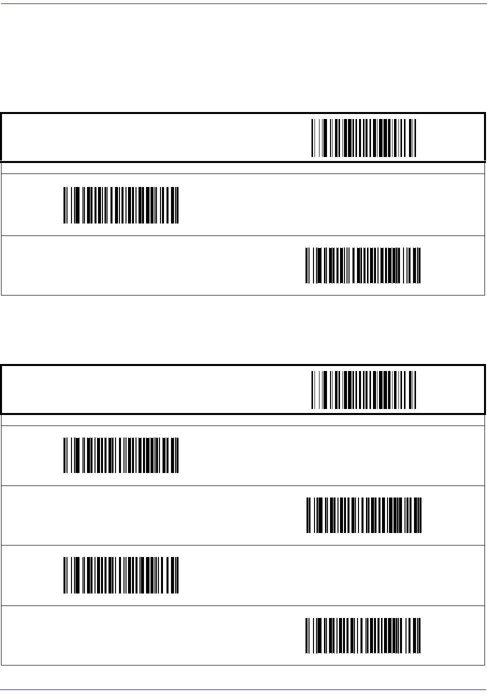
Symbologies
5-38 Magellan
®
1000i
Code 128 — continued
Code 128 Stitching
Enables/disables stitching for Code 128 labels. When parts of a Code 128 barcode are presented
to the scanner with this feature enabled, the barcode parts will be assembled by the scanner’s
software, and the data will be decoded if all barcode proofing requirements are met.
Minimum Reads
This feature specifies the minimum number of consecutive times a Code 128 label must be
decoded before it is accepted as good read.
START / END
PROGRAMMING BARCODES
Disable Code 128 Stitching
DEFAULT
Enable Code 128 Stitching
START / END
PROGRAMMING BARCODES
Minimum = 1 Read
DEFAULT
Minimum = 2 Reads
Minimum = 3 Reads
Minimum = 4 Reads
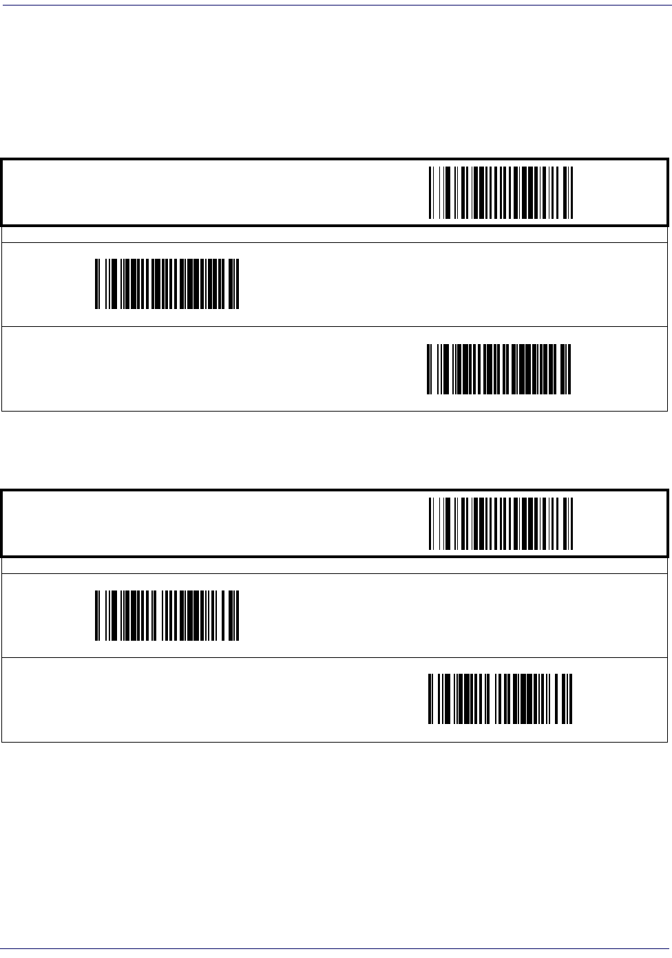
Interleaved 2 of 5
Product Reference Guide
5-39
Interleaved 2 of 5
The following options apply to the Interleaved 2 of 5 (I 2 of 5) symbology.
Disable/Enable Interleaved 2 of 5
When this feature is disabled, the scanner will not read Interleaved 2 of 5 barcodes.
Check Digit Calculation
When enabled, the scanner will calculate the check digit of the labels.
START / END
PROGRAMMING BARCODES
Disable Interleaved 2 of 5
DEFAULT
Enable Interleaved 2 of 5
START / END
PROGRAMMING BARCODES
Disable Check Digit Calculation
DEFAULT
Enable Check Digit Calculation

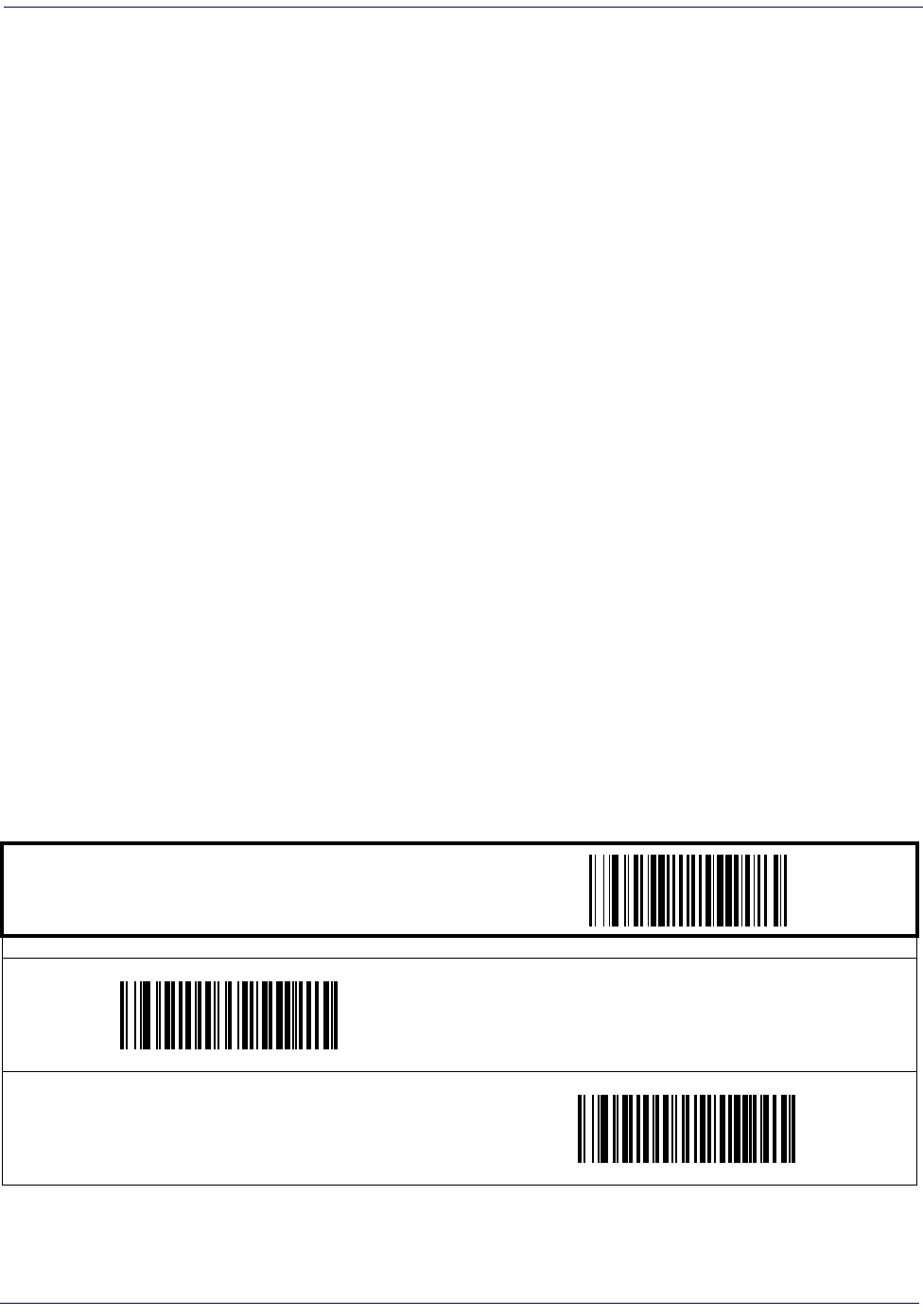
Interleaved 2 of 5
Product Reference Guide
5-41
Interleaved 2 of 5 — continued
Length Control
Fixed Length Decoding—
When fixed length decoding is enabled, the scanner will decode a
barcode if the label length matches one of the configurable fixed lengths.
Variable Length Decoding—
When variable length decoding is enabled, the scanner will
decode a barcode if the label length falls in the range of the configurable minimum and maxi-
mum length.
Configuring Fixed Length Decoding:
1. Scan the START barcode.
2. Scan the Fixed Length Decoding barcode.
3. Scan the END barcode.
4. Set Length 1 to the first fixed length by following the Interleaved 2 of 5 Length 1, Length 2
Programming Instructions below.
5. Set Length 2 to the second fixed length (or to ‘000’ if there is only one fixed length) by
following the Interleaved 2 of 5 Length 1, Length 2 Programming Instructions below.
Configuring Variable Length Decoding:
1. Scan the START barcode.
2. Scan the Variable Length Decoding barcode.
3. Scan the END barcode.
4. Set Length 1 to the first variable length by following the Interleaved 2 of 5 Length 1, Length
2 Programming Instructions below.
5. Set Length 2 to the second variable length by following the Interleaved 2 of 5 Length 1,
Length 2 Programming Instructions below.
START / END
PROGRAMMING BARCODES
Variable Length Decoding
DEFAULT
Fixed Length Decoding
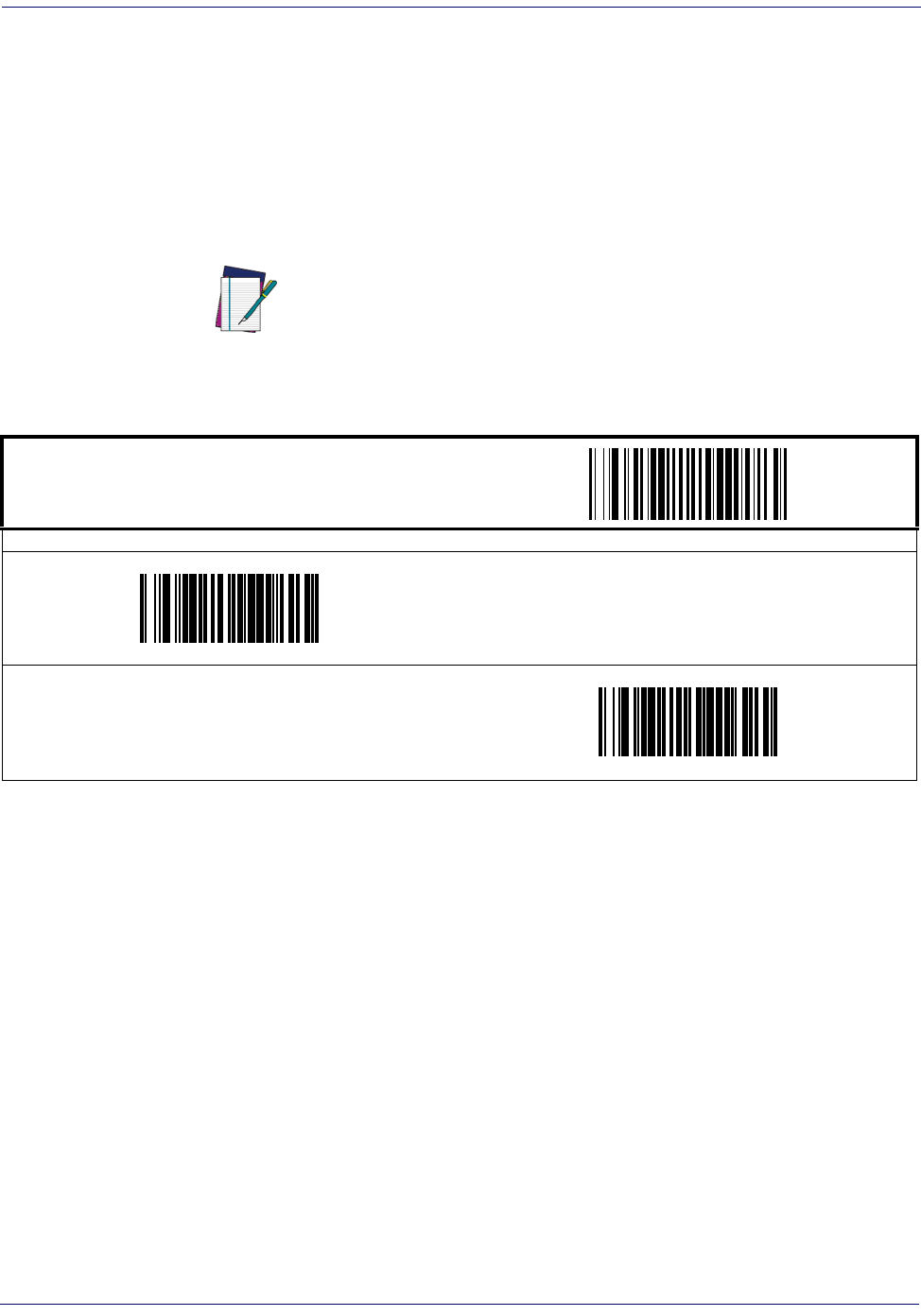
Symbologies
5-42 Magellan
®
1000i
Interleaved 2 of 5 — continued
Interleaved 2 of 5 Length 1, Length 2 Programming Instructions
1. Scan the START barcode.
2. Scan either the Set Length 1 or Set Length 2 barcode.
3. Turn to Appendix C, Alpha-Numeric Pad and scan the three digits (zero padded) represent-
ing the length in decimal notation.
4. Scan the END barcode.
NOTE
For Interleaved 2 of 5 barcodes, lengths must be
an even number. Additionally, all check and data
characters are included in the length calcula-
tions.
START / END
PROGRAMMING BARCODES
DEFAULT SETTING FOR THIS FEATURE: 006
Set Length 1
Set Length 2
DEFAULT SETTING FOR THIS FEATURE: 050
Interleaved 2 of 5
Product Reference Guide
5-43
Interleaved 2 of 5 — continued
Interleaved 2 of 5 Stitching
Enables/disables stitching for Interleaved 2 of 5 labels. When parts of an Interleaved 2 of 5 bar-
code are presented to the scanner with this feature enabled, the barcode parts will be assembled
by the scanner’s software, and the data will be decoded if all barcode proofing requirements are
met.
NOTE
Only functions when Fixed Length Decoding is enabled.
START / END
PROGRAMMING BARCODES
Disable Interleaved 2 of 5 Stitching
DEFAULT
Enable Interleaved 2 of 5 Stitching
Symbologies
5-44 Magellan
®
1000i
Interleaved 2 of 5 — continued
Minimum Reads
This feature specifies the minimum number of consecutive times an Interleaved 2 of 5 label
must be decoded before it is accepted as good read.
START / END
PROGRAMMING BARCODES
Minimum = 1 Read
DEFAULT
Minimum = 2 Reads
Minimum = 3 Reads
Minimum = 4 Reads
Codabar
Product Reference Guide
5-45
Codabar
The following options apply to the Codabar symbology.
Disable/Enable Codabar
When this feature is disabled, the scanner will not read Codabar barcodes.
Check Character Verification
When enabled, the scanner will verify the check character of the labels.
START / END
PROGRAMMING BARCODES
Disable Codabar
DEFAULT
Enable Codabar
START / END
PROGRAMMING BARCODES
Disable Check Char Verification
DEFAULT
Enable Check Char Verification
Symbologies
5-46 Magellan
®
1000i
Check Character Transmit
Enable this option to transmit the check character with scanned barcode data.
START / END
PROGRAMMING BARCODES
Disable Check Char Transmission
Enable Check Char Transmission
DEFAULT
Codabar
Product Reference Guide
5-47
Codabar — continued
Length Control
Fixed Length Decoding—
When fixed length decoding is enabled, the scanner will decode a
barcode if the label length matches one of the configurable fixed lengths.
Variable Length Decoding—
When variable length decoding is enabled, the scanner will
decode a barcode if the label length falls in the range of the configurable minimum and maxi-
mum length.
Configuring Fixed Length Decoding:
1. Scan the START barcode.
2. Scan the Fixed Length Decoding barcode.
3. Scan the END barcode.
4. Set Length 1 to the first fixed length by following the Codabar Length 1, Length 2 Program-
ming Instructions below.
5. Set Length 2 to the second fixed length (or to ‘000’ if there is only one fixed length) by
following the Codabar Length 1, Length 2 Programming Instructions below.
Configuring Variable Length Decoding:
1. Scan the START barcode.
2. Scan the Variable Length Decoding barcode.
3. Scan the END barcode.
4. Set Length 1 to the first variable length by following the Codabar Length 1, Length 2 Pro-
gramming Instructions below.
5. Set Length 2 to the second variable length by following the Codabar Length 1, Length 2
Programming Instructions below.
START / END
PROGRAMMING BARCODES
Variable Length Decoding
DEFAULT
Fixed Length Decoding
Symbologies
5-48 Magellan
®
1000i
Codabar — continued
Codabar Length 1, Length 2 Programming Instructions
1. Scan the START barcode.
2. Scan either the Set Length 1 or Set Length 2 barcode.
3. Turn to Appendix C, Alpha-Numeric Pad and scan the three digits (zero padded) represent-
ing the length in decimal notation.
4. Scan the END barcode.
Quiet Zones
This feature enable/disables the requirement that quiet zones must be present for Codabar bar-
codes.
NOTE
For Codabar barcodes, all start, stop, check and
data characters are included in the length calcu-
lations.
START / END
PROGRAMMING BARCODES
DEFAULT SETTING FOR THIS FEATURE: 003
Set Length 1
Set Length 2
DEFAULT SETTING FOR THIS FEATURE: 050
START / END
PROGRAMMING BARCODES
Don’t require Quiet Zones
DEFAULT
Require Quiet Zones
Codabar
Product Reference Guide
5-49
Codabar — continued
Start/Stop Character Type
Codabar has four pairs of Start/Stop patterns. Select one pair to match your application.
Start/Stop Character Transmission
The transmission of start and end characters of Codabar is selected below.
START / END
PROGRAMMING BARCODES
Start/Stop Type: ABCD/TN*E
Start/Stop Type: ABCD/ABCD
Start/Stop Type: abcd/tn*e
Start/Stop Type: abcd/abcd
DEFAULT
START / END
PROGRAMMING BARCODES
Disable Start/Stop Char Transmission
Enable Start/Stop Char Transmission
DEFAULT
Symbologies
5-50 Magellan
®
1000i
Start/Stop Character Match
This feature enables/disables the requirement that start and stop characters match.
Codabar Stitching
Enables/disables stitching for Codabar labels. When parts of a Codabar label are presented to
the scanner with this feature enabled, the barcode parts will be assembled by the scanner’s soft-
ware, and the data will be decoded if all barcode proofing requirements are met.
START / END
PROGRAMMING BARCODES
Disable Start/Stop Char Match
DEFAULT
Enable Start/Stop Char Match
NOTE
Only functions when Fixed Length Decoding is enabled.
START / END
PROGRAMMING BARCODES
Disable Codabar Stitching
DEFAULT
Enable Codabar Stitching
Codabar
Product Reference Guide
5-51
Codabar — continued
Minimum Reads
This feature specifies the minimum number of consecutive times a Codabar label must be
decoded before it is accepted as a good read.
START / END
PROGRAMMING BARCODES
Minimum = 1 Read
DEFAULT
Minimum = 2 Reads
Minimum = 3 Reads
Minimum = 4 Reads
Symbologies
5-52 Magellan
®
1000i
Code 93
The following options apply to the Code 93 symbology.
Disable/Enable Code 93
When this feature is disabled, the scanner will not read Code 93 barcodes.
START / END
PROGRAMMING BARCODES
Disable Code 93
DEFAULT
Enable Code 93
Code 93
Product Reference Guide
5-53
Code 93 — continued
Length Control
Fixed Length Decoding—
When fixed length decoding is enabled, the scanner will decode a
barcode if the label length matches one of the configurable fixed lengths.
Variable Length Decoding—
When variable length decoding is enabled, the scanner will
decode a barcode if the label length falls in the range of the configurable minimum and maxi-
mum length.
Configuring Fixed Length Decoding:
1. Scan the START/END barcode.
2. Scan the Fixed Length Decoding barcode.
3. Scan the START/END barcode.
4. Set Length 1 to the first fixed length by following the Code 93 Length 1, Length 2 Program-
ming Instructions below.
5. Set Length 2 to the second fixed length (or to ‘000’ if there is only one fixed length) by
following the Code 93 Length 1, Length 2 Programming Instructions below.
Configuring Variable Length Decoding:
1. Scan the START/END barcode.
2. Scan the Variable Length Decoding barcode.
3. Scan the START/END barcode.
4. Set Length 1 to the first variable length by following the Code 93 Length 1, Length 2 Pro-
gramming Instructions below.
5. Set Length 2 to the second variable length by following the Code 93 Length 1, Length 2 Pro-
gramming Instructions below.
START / END
PROGRAMMING BARCODES
Variable Length Decoding
DEFAULT
Fixed Length Decoding
Symbologies
5-54 Magellan
®
1000i
Code 93 — continued
Code 93 Length 1, Length 2 Programming Instructions
1. Scan the START barcode.
2. Scan either the Set Length 1 or Set Length 2 barcode.
3. Turn to Appendix C, Alpha-Numeric Pad and scan the three digits (zero padded) represent-
ing the length in decimal notation.
4. Scan the END barcode.
NOTE
For Code 93 barcodes, only the data characters
are included in the length calculations.
START / END
PROGRAMMING BARCODES
DEFAULT SETTING FOR THIS FEATURE: 001
Set Length 1
Set Length 2
DEFAULT SETTING FOR THIS FEATURE: 050
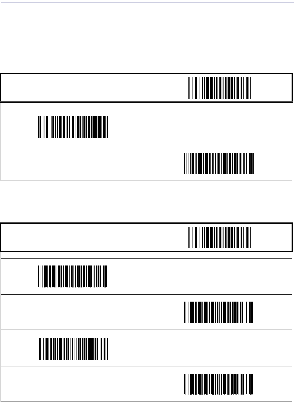
Code 93
Product Reference Guide
5-55
Code 93 — continued
Code 93 Stitching
Enables/disables stitching for Code 93 barcodes. When parts of a Code 93 label are presented to
the scanner with this feature enabled, the barcode parts will be assembled by the scanner’s soft-
ware, and the data will be decoded if all barcode proofing requirements are met.
Minimum Reads
This feature specifies the minimum number of consecutive times a Code 93 label must be
decoded before it is accepted as a good read.
START / END
PROGRAMMING BARCODES
Disable Code 93 Stitching
DEFAULT
Enable Code 93 Stitching
START / END
PROGRAMMING BARCODES
Minimum = 1 Read
DEFAULT
Minimum = 2 Reads
Minimum = 3 Reads
Minimum = 4 Reads
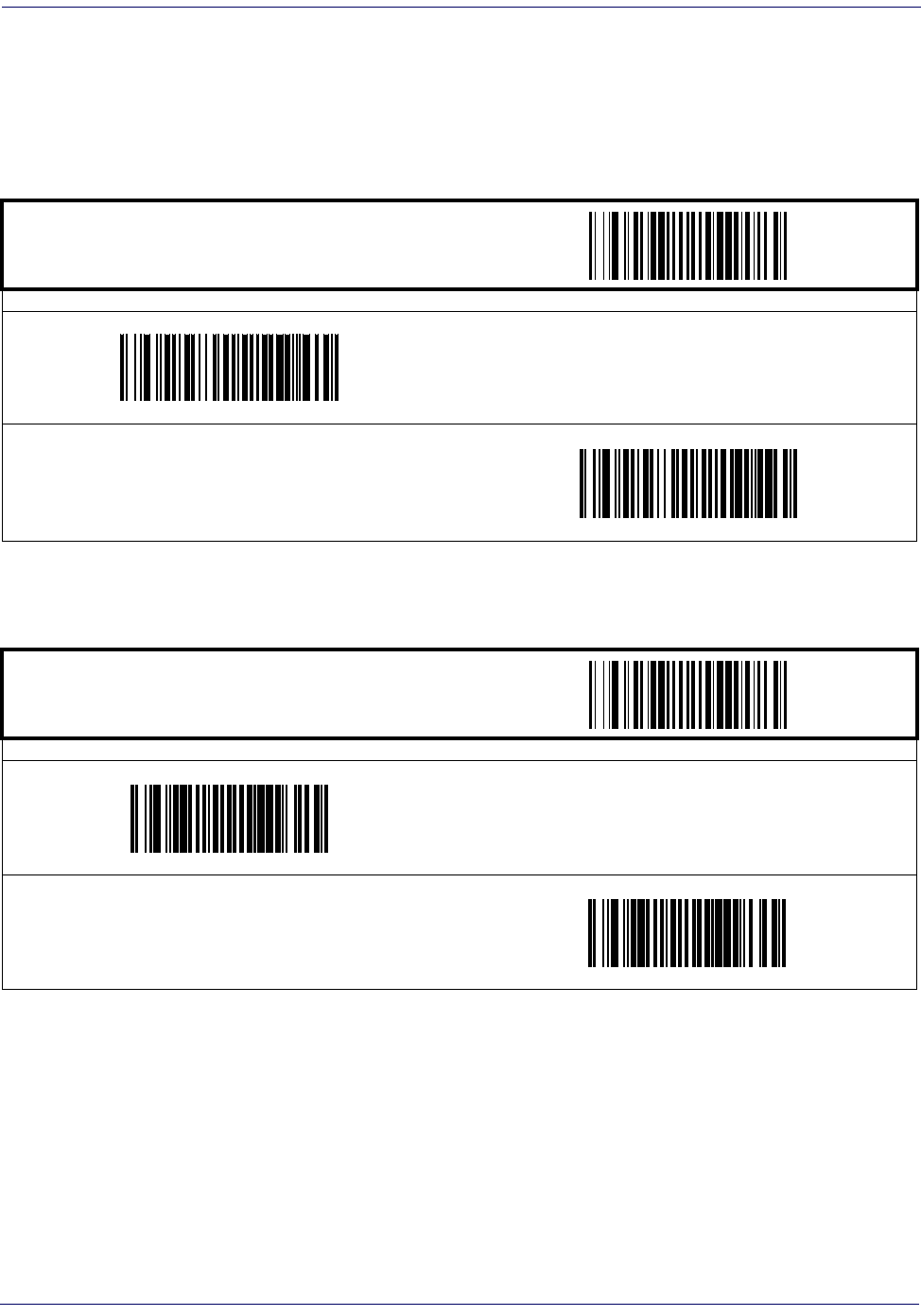
Symbologies
5-56 Magellan
®
1000i
MSI/Plessey
The following options apply to the MSI/Plessey symbology.
Disable/Enable MSI/Plessey
When this feature is disabled, the scanner will not read MSI/Plessey barcodes.
Check Digit Verification
This feature specifies whether one or two check digits are to be calculated and verified.
START / END
PROGRAMMING BARCODES
Disable MSI/Plessey
DEFAULT
Enable MSI/Plessey
START / END
PROGRAMMING BARCODES
Disable Check Digit Verification
DEFAULT
Enable Check Digit Verification
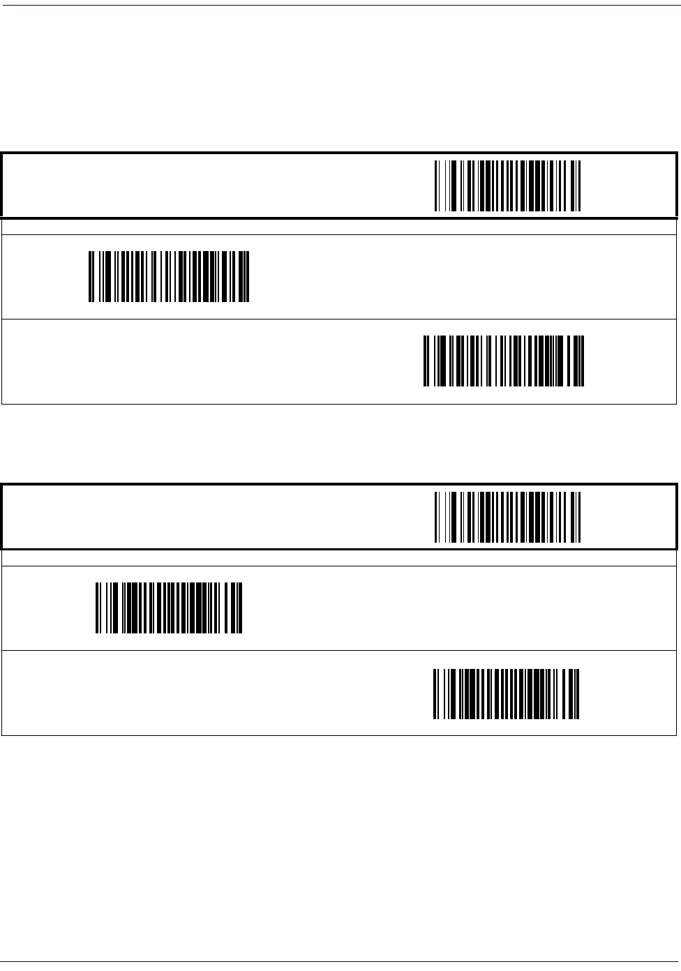
MSI/Plessey
Product Reference Guide
5-57
MSI/Plessey — continued
Check Digit Transmit
When this option is enabled, the scanner will transmit one-digit or two-digit check digits,
depending upon the setting for check digit verification.
Number of Check Characters
Specifies number of MSI/Plessey check characters to be calculated and verified
START / END
PROGRAMMING BARCODES
Disable Check Digit Transmission
Enable Check Digit Transmission
DEFAULT
START / END
PROGRAMMING BARCODES
1 Check Character
DEFAULT
2 Check Characters
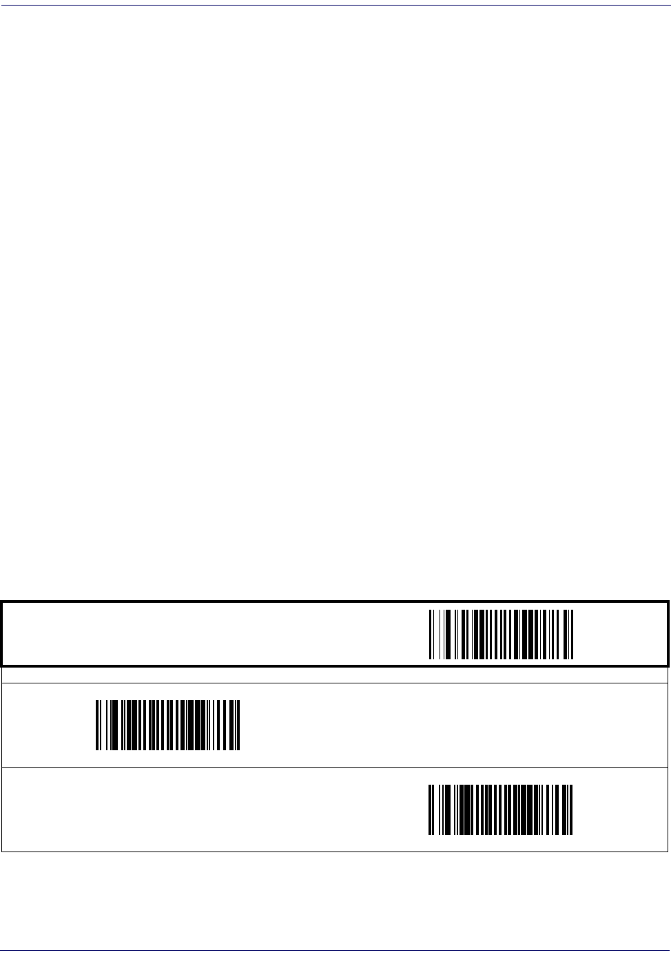
Symbologies
5-58 Magellan
®
1000i
MSI/Plessey — continued
Length Control
Fixed Length Decoding—
When fixed length decoding is enabled, the scanner will decode a
barcode if the label length matches one of the configurable fixed lengths.
Variable Length Decoding—
When variable length decoding is enabled, the scanner will
decode a barcode if the label length falls in the range of the configurable minimum and maxi-
mum length.
Configuring Fixed Length Decoding:
1. Scan the START/END barcode.
2. Scan the Fixed Length Decoding barcode.
3. Scan the START/END barcode.
4. Set Length 1 to the first fixed length by following the MSI/Plessey Length 1, Length 2 Pro-
gramming Instructions below.
5. Set Length 2 to the second fixed length (or to ‘000’ if there is only one fixed length) by
following the MSI/Plessey Length 1, Length 2 Programming Instructions below.
Configuring Variable Length Decoding:
1. Scan the START/END barcode.
2. Scan the Variable Length Decoding barcode.
3. Scan the START/END barcode.
4. Set Length 1 to the first variable length by following the MSI/Plessey Length 1, Length 2
Programming Instructions below.
5. Set Length 2 to the second variable length by following the MSI/Plessey Length 1, Length 2
Programming Instructions below.
START / END
PROGRAMMING BARCODES
Variable Length Decoding
DEFAULT
Fixed Length Decoding
³
MSI/Plessey
Product Reference Guide
5-59
MSI/Plessey — continued
MSI/Plessey Length 1, Length 2 Programming Instructions
1. Scan the START barcode.
2. Scan either the Set Length 1 or Set Length 2 barcode.
3. Turn to Appendix C, Alpha-Numeric Pad and scan the three digits (zero padded) represent-
ing the length in decimal notation.
4. Scan the END barcode.
NOTE
For MSI/Plessey barcodes, all check and data char-
acters are included in the length calculations.
START / END
PROGRAMMING BARCODES
DEFAULT SETTING FOR THIS FEATURE: 004
Set Length 1
Set Length 2
DEFAULT SETTING FOR THIS FEATURE: 016
Symbologies
5-60 Magellan
®
1000i
MSI/Plessey — continued
MSI/Plessey Stitching
Enables/disables stitching for MSI/Plessey barcodes. When parts of an MSI/Plessey label are
presented to the scanner with this feature enabled, the barcode parts will be assembled by the
scanner’s software, and the data will be decoded if all barcode proofing requirements are met.
NOTE
Only functions when Fixed Length Decoding is enabled.
START / END
PROGRAMMING BARCODES
Disable MSI/Plessey Stitching
DEFAULT
Enable MSI/Plessey Stitching
MSI/Plessey
Product Reference Guide
5-61
MSI/Plessey — continued
Minimum Reads
This feature specifies the minimum number of consecutive times an MSI/Plessey label must be
decoded before it is accepted as good read.
START / END
PROGRAMMING BARCODES
Minimum = 1 Read
DEFAULT
Minimum = 2 Reads
Minimum = 3 Reads
Minimum = 4 Reads
Symbologies
5-62 Magellan
®
1000i
Standard 2 of 5
The following options apply to the Standard 2 of 5 symbology.
Disable/Enable Standard 2 of 5
When this feature is disabled, the scanner will not read Standard 2 of 5 barcodes.
Check Digit Verification
When enabled, the scanner will verify the check digit of the labels.
START / END
PROGRAMMING BARCODES
Disable Std 2 of 5
DEFAULT
Enable Std 2 of 5
START / END
PROGRAMMING BARCODES
Disable Check Digit Verification
DEFAULT
Enable Check Digit Verification


Symbologies
5-64 Magellan
®
1000i
Standard 2 of 5 — continued
Length Control
Fixed Length Decoding—
When fixed length decoding is enabled, the scanner will decode a
barcode if the label length matches one of the configurable fixed lengths.
Variable Length Decoding—
When variable length decoding is enabled, the scanner will
decode a barcode if the label length falls in the range of the configurable minimum and maxi-
mum length.
Configuring Fixed Length Decoding:
1. Scan the START/END barcode.
2. Scan the Fixed Length Decoding barcode.
3. Scan the START/END barcode.
4. Set Length 1 to the first fixed length by following the Standard 2 of 5 Length 1, Length 2
Programming Instructions below.
5. Set Length 2 to the second fixed length (or to ‘000’ if there is only one fixed length) by
following the Standard 2 of 5 Length 1, Length 2 Programming Instructions below.
Configuring Variable Length Decoding:
1. Scan the START/END barcode.
2. Scan the Variable Length Decoding barcode.
3. Scan the START/END barcode.
4. Set Length 1 to the first variable length by following the Standard 2 of 5 Length 1, Length 2
Programming Instructions below.
5. Set Length 2 to the second variable length by following the Standard 2 of 5 Length 1, Length
2 Programming Instructions below.
START / END
PROGRAMMING BARCODES
Variable Length Decoding
DEFAULT
Fixed Length Decoding
Standard 2 of 5
Product Reference Guide
5-65
Standard 2 of 5 — continued
Standard 2 of 5 Length 1, Length 2 Programming Instructions
1. Scan the START barcode.
2. Scan either the Set Length 1 or Set Length 2 barcode.
3. Turn to Appendix C, Alpha-Numeric Pad and scan the three digits (zero padded) represent-
ing the length in decimal notation.
4. Scan the END barcode.
NOTE
For Standard 2 of 5 barcodes, all check and data
characters are included in the length calcula-
tions.
START / END
PROGRAMMING BARCODES
DEFAULT SETTING FOR THIS FEATURE: 008
Set Length 1
Set Length 2
DEFAULT SETTING FOR THIS FEATURE: 050
Symbologies
5-66 Magellan
®
1000i
Standard 2 of 5 — continued
Standard 2 of 5 Stitching
Enables/disables stitching for Standard 2 of 5 barcodes. When parts of a Standard 2 of 5 label
are presented to the scanner with this feature enabled, the barcode parts will be assembled by the
scanner’s software, and the data will be decoded if all barcode proofing requirements are met.
NOTE
Only functions when Fixed Length Decoding is enabled.
START / END
PROGRAMMING BARCODES
Disable Std 2 of 5 Stitching
DEFAULT
Enable Std 2 of 5 Stitching
Standard 2 of 5
Product Reference Guide
5-67
Standard 2 of 5 — continued
Minimum Reads
This feature specifies the minimum number of consecutive times a Standard 2 of 5 label must be
decoded before it is accepted as good read.
START / END
PROGRAMMING BARCODES
Minimum = 1 Read
DEFAULT
Minimum = 2 Reads
Minimum = 3 Reads
Minimum = 4 Reads

Symbologies
5-68 Magellan
®
1000i

Product Reference Guide
6-1
2D Symbologies & Advanced Decoding
Features
NOTE
The features in this section are available ONLY for models with 2D features
activated.
2D Symbologies & Advanced Decoding Features
6-2 Magellan
®
1000i
2D Symbologies
The scanner supports the following 2D symbologies (barcode types): PDF 417 and Datamatrix.
Options for each symbology are included in this addendum.
Factory Defaults—
for the std. RS-232 interface are indicated in bold text throughout.
PDF 417
Disable/Enable PDF 417
When disabled, the scanner will not read PDF 417 barcodes.
START / END
PROGRAMMING BARCODES
Disable PDF 417
Enable PDF 417
2D Symbologies
Product Reference Guide
6-3
PDF 417 — continued
Length Control
Fixed Length Decoding—
When fixed length decoding is enabled, the scanner will decode a
barcode if the label length matches one of the configurable fixed lengths.
Variable Length Decoding—
When variable length decoding is enabled, the scanner will
decode a barcode if the label length falls in the range of the configurable minimum and maxi-
mum length.
Configuring Fixed Length Decoding:
1. Scan the START barcode.
2. Scan the Fixed Length Decoding barcode.
3. Scan the END barcode.
4. Set Length 1 to the first fixed length by following the Length 1, Length 2 Programming
Instructions below.
5. Set Length 2 to the second fixed length (or to ‘00’ if there is only one fixed length) by fol-
lowing the PDF 417 Length 1, Length 2 Programming Instructions below.
Configuring Variable Length Decoding:
1. Scan the START barcode.
2. Scan the Variable Length Decoding barcode.
3. Scan the END barcode.
4. Set Length 1 to the minimum length by following the PDF 417 Length 1, Length 2 Pro-
gramming Instructions below.
5. Set Length 2 to the maximum length by following the PDF 417 Length 1, Length 2 Pro-
gramming Instructions below.
START / END
PROGRAMMING BARCODES
Variable Length Decoding
Fixed Length Decoding
2D Symbologies & Advanced Decoding Features
6-4 Magellan
®
1000i
PDF 417 — continued
PDF 417 Length 1, Length 2 Programming Instructions
1. Scan the START barcode.
2. Scan either the Set Length 1 or Set Length 2 barcode.
3. Turn to Alpha-Numeric Pad and scan the four hex digits representing the length in hexidec-
imal notation.
Scan the END barcode.
NOTE
For PDF 417 barcodes, only the data characters are included in the
length calculations.
START / END
PROGRAMMING BARCODES
DEFAULT SETTING FOR THIS FEATURE: 01 (0X0001)
Set Length 1
Set Length 2
DEFAULT SETTING FOR THIS FEATURE: 2710 (0x0A96)

2D Symbologies
Product Reference Guide
6-5
PDF 417 — continued
Minimum Reads
This feature specifies the minimum number of consecutive times a PDF 417 label must be
decoded before it is accepted as good read.
START / END
PROGRAMMING BARCODES
Minimum = 1 Read
Minimum = 2 Reads
Minimum = 3 Reads
Minimum = 4 Reads
2D Symbologies & Advanced Decoding Features
6-6 Magellan
®
1000i
Datamatrix
Disable/Enable Datamatrix
When disabled, the scanner will not read Datamatrix barcodes.
START / END
PROGRAMMING BARCODES
Disable Datamatrix
Enable Datamatrix
2D Symbologies
Product Reference Guide
6-7
Datamatrix — continued
Length Control
Fixed Length Decoding—
When fixed length decoding is enabled, the scanner will decode a
barcode if the label length matches one of the configurable fixed lengths.
Variable Length Decoding—
When variable length decoding is enabled, the scanner will
decode a barcode if the label length falls in the range of the configurable minimum and maxi-
mum length.
Configuring Fixed Length Decoding:
1. Scan the START barcode.
2. Scan the Fixed Length Decoding barcode.
3. Scan the END barcode.
4. Set Length 1 to the first fixed length by following the Length 1, Length 2 Programming
Instructions below.
5. Set Length 2 to the second fixed length (or to ‘00’ if there is only one fixed length) by fol-
lowing the Datamatrix Length 1, Length 2 Programming Instructions below.
Configuring Variable Length Decoding:
1. Scan the START barcode.
2. Scan the Variable Length Decoding barcode.
3. Scan the END barcode.
4. Set Length 1 to the minimum length by following the Datamatrix Length 1, Length 2 Pro-
gramming Instructions below.
5. Set Length 2 to the maximum length by following the Datamatrix Length 1, Length 2 Pro-
gramming Instructions below.
START / END
PROGRAMMING BARCODES
Variable Length Decoding
Fixed Length Decoding
2D Symbologies & Advanced Decoding Features
6-8 Magellan
®
1000i
Datamatrix — continued
Datamatrix Length 1, Length 2 Programming Instructions
1. Scan the START barcode.
2. Scan either the Set Length 1 or Set Length 2 barcode.
3. Turn to Alpha-Numeric Pad and scan the four hex digits representing the length in hexidec-
imal notation.
Scan the END barcode.
NOTE
For Datamatrix barcodes, only the data characters are included in the
length calculations.
START / END
PROGRAMMING BARCODES
DEFAULT SETTING FOR THIS FEATURE: 1 (0x0001)
Set Length 1
Set Length 2
DEFAULT SETTING FOR THIS FEATURE: 800 (0x0320)
2D Symbologies
Product Reference Guide
6-9
Datamatrix — continued
Minimum Reads
This feature specifies the minimum number of consecutive times a Datamatrix label must be
decoded before it is accepted as good read.
START / END
PROGRAMMING BARCODES
Minimum = 1 Read
Minimum = 2 Reads
Minimum = 3 Reads
Minimum = 4 Reads

2D Symbologies & Advanced Decoding Features
6-10 Magellan
®
1000i
Image Capture
How to Capture an Image
To initiate an Image Capture, scan the IMAGE CAPTURE label below, and press the button. A
targeting “pointer” will be illuminated while the button is pressed.
Upon release of the button, the image is captured and transmitted to the host. If the button is
not pushed within 30 seconds, the scanner will return to barcode reading (scanning) mode.
IMAGE CAPTURE
Captured Image Format
Images are captured as 752 x 480 JPEG format with a pre-defined compression ratio, and are
displayed via the host application software.
NOTE
This function is ONLY available for scanners having a button.
Image capture requires that the scanner use the Standard RS-232 or USB
COM interface ONLY.
The scanner reverts to default reading mode after image capture and trans-
fer.
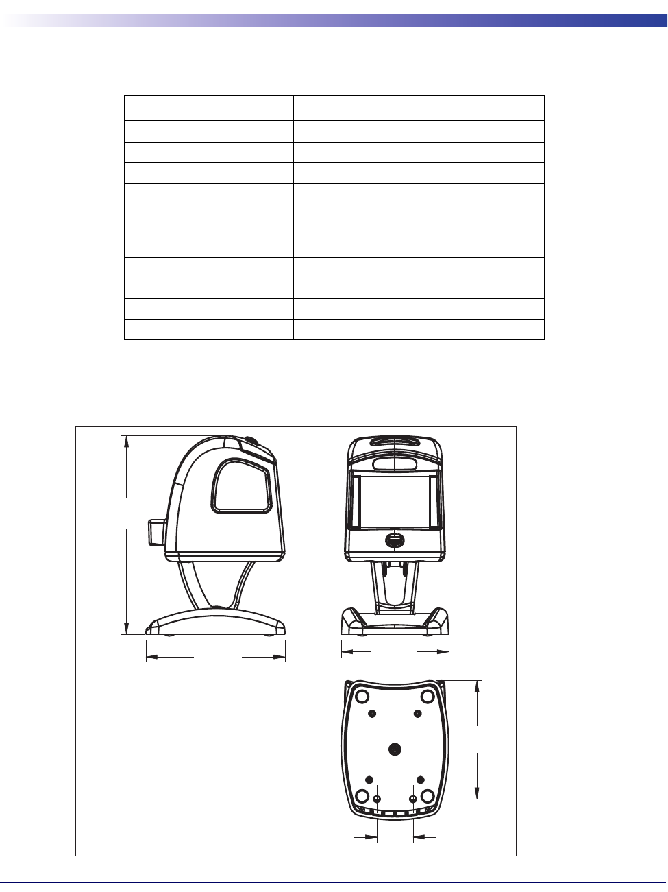
Product Reference Guide
A-1
Chapter A
Product Specifications
Optical and Read Performance Parameters
Scanner Dimensions
Parameter Specification
Scan Volume 70 cubic inches
Scan Pattern 100 lines
Scan Rate 1,100 digital scan lines
Minimum Resolution 5 mil
Depth of Field
(100% UPC Labels)
0 - 6”
Minimum Print Contrast Ratio 25%
Skew (Yaw) ± 75
Pitch ± 65
Roll Between 0 and 360
139.58mm
5.5"
97.84mm
3.85"
75.44mm
2.97"
83.25mm
3.28"
25.4mm
1.0"

A-2 Magellan
®
1000i
Physical Properties
Electrical Parameters
Environmental Parameters
Other Parameters
Parameter Specification
Dimensions (Scanner only): 3.3” x2.8” x3.7”
Dimensions (Scanner w/Base
Station): 5.5” x2.9” x3.8”
Weight (Scanner) 7.0 oz.
Weight (Base Station) 6.6 oz.
Parameter Specification
Operating Voltage
(Two Models)
5V unit = 5.0V ± 5%
12V unit = 7-12V
Input Current
Operating (idle)
Operating (label read)
<300mA
<400 mA
Parameter Specification
Mechanical Shock Multi 1.2m drops
Contaminants
Water and Dust
IP52
Temperature Ranges:
Operating 32 F to +104 F (0 C to +40 C)
Storage -40 F to +158 F (-40 C to + 70C)
Ambient Light Indoor 40 - 6000 lux
Ambient Light Outdoor 40 - 86,100 lux
Humidity 5 to 95% non-condensing
Beeper/Speaker 70-85dBA at a distance of 3’-3” (1 meter)
Vibration Retail/Office
Parameter Specification
EAS Support YES (Checkpoint)
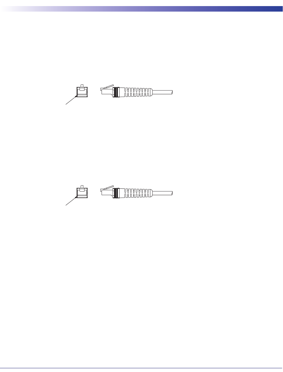
Product Reference Guide
B-1
Chapter B
Cable Pinouts
Standard Cable Pinouts (Primary Interface Cables)
RS-232
IBM Port 5B/9B/17
1
2CTS
3
4RTS
5RXD
6TXD
7
8 VCC IN
9GND
10
1
2
3
4DATA -
5
6DATA +
7
8VCC_IN
9GND
10
Pin 1
10 Position RJ
(Scanner End)
Pin 1
10 Position RJ
(Scanner End)
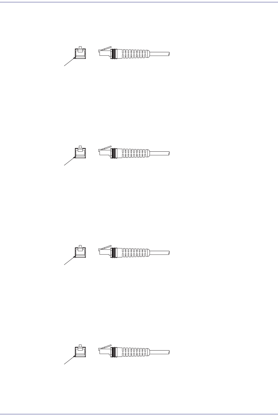
Cable Pinouts
B-2 Magellan
®
1000i
USB-OEM
USB, USB Keyboard & USB COM
Wand Emulation
Keyboard Wedge
1
2
3
4D -
5
6D +
7
8VIN
9GND
10
1
2
3
4D -
5
6D +
7
8 VBUS_VIN
9GND
10
1
2
3 WAND~
4
5
6
7
8VCC_IN
9GND
10
1
2 KB_DATA
3AT_CLK
4 KB_CLK
5
6AT_DATA
7
8VCC_IN
9GND
10
Pin 1
10 Position RJ
(Scanner End)
Pin 1
10 Position RJ
(Scanner End)
Pin 1
10 Position RJ
(Scanner End)
Pin 1
10 Position RJ
(Scanner End)

Product Reference Guide
C-1
Chapter C
Alpha-Numeric Pad
A
B
C
D
E
F

C-2 Magellan
®
1000i
Alpha-Numeric Pad
1
2
3
0
9
8
7
6
5
4

Product Reference Guide
D-1
Appendix D
Default Settings
Defaults by Symbology
The following is a partial list of key settings for each symbology type.
Code Type Read
Enable
Checksum
Verification
Enable
Checksum
Transmission
Enable
Label
ID
UPC-A ✓✓ ✓ A
UPC-E ✓✓ ✓ E
EAN-13 ✓✓ ✓ F
EAN-8 ✓✓ ✓FF
GS1 DataBar
Omnidirectional R4
GS1 Expanded RX
Code 39 ✓✓
*
PharmaCode 39 A
Code 128 ✓#
Interleaved 2 of 5 ✓i
Codabar ✓%
Code 93 &
MSI/Plessey ✓@
Standard 2 of 5 ✓s
PDF 417 P
Datamatrix Dm

D-2 Magellan
®
1000i
Interface Default Exceptions
The factory default settings indicated in the programming sections (in bold text) reflect factory configuration for
the RS-232 standard interface. The following tables list default exceptions by interface for the remaining available
interfaces.
IBM Interfaces
IBM Interfaces include USB-OEM, IBM Port 9B, IBM Port5B and IBM Port17.
Parameter Default Setting
IBM Interface Type IBM Port 9B
Number of Host Transmit Buffers One Buffer
Label I.D. Transmission Disable
Suffix Characters No Suffix

Interface Default Exceptions
Product Reference Guide
D-3
Interface Default Exceptions — continued
RS-232 Wincor/Nixdorf
Parameter Default Setting
Interface Type RS-232-WN
Number of Host Transmit Buffers One Buffer
RS-232 Parity Odd
RS-232 Hardware Control CTS Flow Control
UPC-E Check Character Conversion Disabled
UCC/EAN-128 Label ID ‘P’
Code 39 Label ID ‘M’
Code 93 Label ID ‘L’
Code 128 Label ID ‘K’
Codabar Label ID ‘N’
EAN-8 Label ID ‘B’
EAN-13 Label ID ‘A’
ISBN Label ID ‘A’
Interleaved 2 of 5 Label ID ‘I’
Standard 2 of 5 Label ID ‘H’
MSI/Plessey Label ID ‘O’
UPC-E Label ID ‘C’
GS1 DataBar Omnidirectional Label ID ‘E’
GS1 Expanded Label ID ‘E’
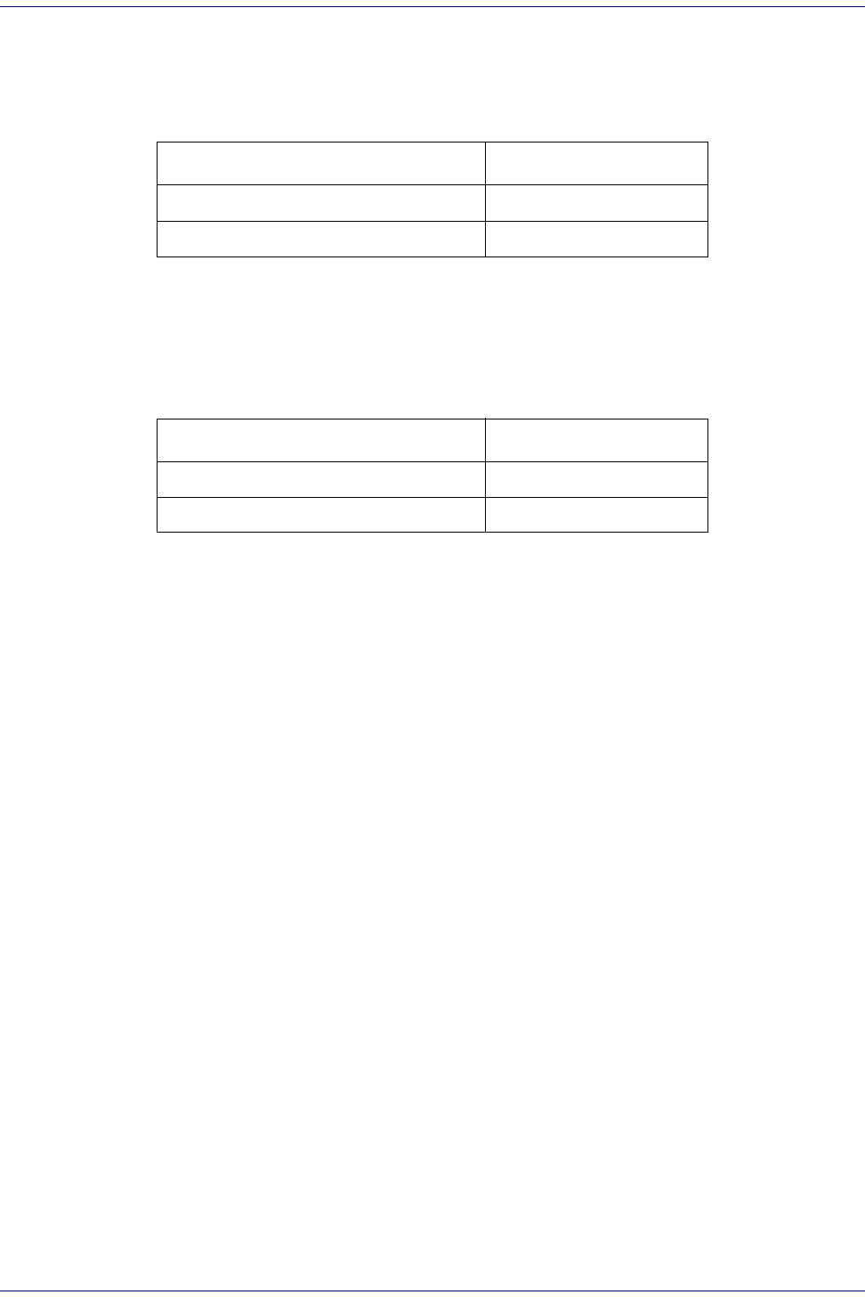
D-4 Magellan
®
1000i
Interface Default Exceptions — continued
Wand Emulation
Keyboards
Keyboard interfaces include USB Keyboard and Keyboard Wedge A-Y.
Parameter Default Setting
Interface Type Wand Emulation
Code 39 Start/Stop Character Transmission Enable
Parameter Default Setting
Keyboard Wedge Interface Type USB Keyboard
Label ID Transmission Disable

Product Reference Guide
E-1
Appendix E
Keyboard Function Key Mappings
Keyboard Model Cross Reference
Ta bl e E - 1 summarizes the keyboard models, their defined protocol, scancode set, and some unique features. The
remaining tables in this chapter provide the function key maps associated with each of the scancode sets.
Table E-1. Keyboard Model Cross Reference
Model Type I/F ID
Trans-
mission
Protocol
Scancode
Set
Func.
Key
Map
Support
Use
Country
Mode
PC/XT Foreign ALT Mode Wedge A PC/XT Scan Set 1 No No
AT;
PS/2 25-286;
PS/2 30-286;
PS/2 50, 50Z;
PS/2 60,70,80,90,95
Foreign ALT Mode
Wedge B AT/PS2 Scan Set 2 No No
PS/2 25 and 30
Foreign ALT Mode Wedge C AT/PS2 Scan Set 1 No No
PC/XT U.S. Mode Wedge D PC/XT Scan Set 1 Yes No
AT;
PS/2 25-286;
PS/2 30-286;
PS/2 50, 50Z;
PS/2 60,70,80,90,95
U.S. Mode + specific
country support
Wedge E AT/PS2 Scan Set 2 Yes Yes
PS/2 25 and 30
U.S. Mode Wedge F AT/PS2 Scan Set 1 Yes No
IBM 3xxx Terminals
(122-key keyboard) Wedge G AT/PS2 Scan Set 3 Yes No
IBM 3xxx Terminals
(102-key keyboard) Wedge H AT/PS2 Scan Set 3 Yes No
PS55 5530T with
JAPANESE DOS (TDOS) Wedge I AT/PS2 Japanese
DOS Ye s N o
NEC 9801 Wedge J NEC
9801 NEC 9801 Yes No
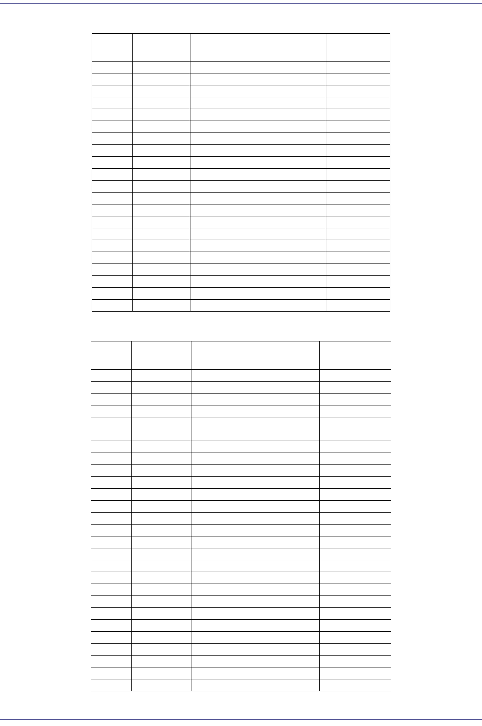
E-2 Magellan
®
1000i
Table E-2. Scanset 1 Function Key Map
Table E-3. Scanset 2 Function Key Map
ASCII
(hex) ASCII code Key Scancode
00 NUL ALT right Make E0h 38h
01 SOH ALT right Break E0h B8h
02 STX ALT left Make 38h
03 ETX ALT left Break B8h
04 EOT CTRL left Make 1Dh
05 ENQ CTRL left Break 9Dh
06 ACK CTRL right Make E0h 1Dh
07 BEL CTRL right Break E0h 9Dh
08 BS BS 0Eh
09 HT TAB right 0Fh
0A LF RIGHT arrow (inner keypad) 4Dh + E0
0B VT TAB left 0Fh + S
0C FF Enter (inner keypad) 1Ch + E0
0D CR CR 1Ch
0E SO INSERT (inner keypad) 52h + E0
0F SI PAGE UP (inner keypad) 49h + E0
10 DLE PAGE DOWN (inner keypad) 51h + E0
11 DC1 HOME (inner keypad) 47h + E0
12 DC2 LEFT arrow (inner keypad) 4Bh + E0
13 DC3 DOWN arrow (inner keypad) 50h + E0
14 DC4 UP arrow (inner keypad) 48h + E0
ASCII
(hex) ASCII code Key Scancode
00 NUL ALT right Make E0h 11h
01 SOH ALT right Break E0h F0h 11h
02 STX ALT left Make 11h
03 ETX ALT left Break F0h 11h
04 EOT CTRL left Make 14h
05 ENQ CTRL left Break F0h 14h
06 ACK CTRL right Make E0h 14h
07 BEL CTRL right Break E0h F0h 14h
08 BS BS 66h
09 HT TAB right 0Dh
0A LF RIGHT arrow (inner keypad) 74h + E0
0B VT TAB left 0Dh + S
0C FF Enter (right keypad) 5Ah + E0
0D CR CR 5Ah
0E SO INSERT (inner keypad) 70h + E0
0F SI PAGE UP (inner keypad) 7Dh + E0
10 DLE PAGE DOWN (inner keypad) 7Ah + E0
11 DC1 HOME (inner keypad) 6Ch + E0
12 DC2 LEFT arrow (inner keypad) 6Bh + E0
13 DC3 DOWN arrow (inner keypad) 72h + E0
14 DC4 UP arrow (inner keypad) 75h + E0
15 NAK F6 0Bh
16 SYN F1 05h
17 ETB F2 06h
18 CAN F3 04h
19 EM F4 0Ch
1A SUB F5 03h

Keyboard Model Cross Reference
Product Reference Guide
E-3
Table E-4
.
Scanset 3, 102-Key Function Key Map
1B ESC ESC 76h
1C FS F7 83h
1D GS F8 0Ah
1E RS F9 01h
1F US F10 09h
ASCII (hex) ASCII code Key Scancode
00 NUL ALT right Make 39h
01 SOH ALT right Break F0h 39h
02 STX ALT left Make 19h
03 ETX ALT left Break F0h 19h
04 EOT CTRL left Make 11h
05 ENQ CTRL left Break F0h 11h
06 ACK CTRL right Make 58h
07 BEL CTRL right Break F0h 58h
08 BS BS 66h
09 HT TAB right 0Dh
0A LF RIGHT arrow (inner keypad) 6Ah
0B VT TAB left 0Dh + S
0C FF Enter (inner keypad) 79h
0D CR CR 5Ah
0E SO INSERT (inner keypad) 67h
0F SI PAGE UP (inner keypad) 6Fh
10 DLE PAGE DOWN (inner keypad) 6Dh
11 DC1 HOME (inner keypad) 6Eh
12 DC2 LEFT arrow (inner keypad) 61h
13 DC3 DOWN arrow (inner keypad) 60h
14 DC4 UP arrow (inner keypad) 63h
15 NAK F6 2Fh
16 SYN F1 07h
17 ETB F2 0Fh
18 CAN F3 17h
19 EM F4 1Fh
1A SUB F5 27h
1B ESC ESC 08h
1C FS F7 37h
1D GS F8 3Fh
1E RS F9 47h
1F US F10 4Fh

E-4 Magellan
®
1000i
Table E-5. Scanset 3 122-Key Function Key Map
ASCII (hex) ASCII code Key Scancode
00 NUL ALT Right Make 39h
01 SOH ALT Right Break F0h 39h
02 STX ALT left Make 19h
03 ETX ALT left Break F0h 19h
04 EOT CTRL left (RESET) Make only 11h
05 ENQ CTRL left (RESET) Make/Break 11h F0h 11h
06 ACK ONLINE Enter Make only 58h
07 BEL ONLINE Enter Make/Break 58h F0h 58h
08 BS BS 66h
09 HT TAB right 0Dh
0A LF RIGHT arrow (inner keypad) 6Ah
0B VT TAB left 0Dh + S
0C FF CR (FIELD EXIT) Make only 5Ah F0h 5Ah
0D CR CR (FIELD EXIT) Make/Break 5Ah
0E SO INSERT (inner keypad) 65h
0F SI FIELD + 79h
10 DLE FIELD - 7Ch
11 DC1 HOME (inner keypad) 62h
12 DC2 LEFT arrow (inner keypad) 61h
13 DC3 DOWN arrow (inner keypad) 60h
14 DC4 UP arrow (inner keypad) 63h
15 NAK F6 2Fh
16 SYN F1 07h
17 ETB F2 0Fh
18 CAN F3 17h
19 EM F4 1Fh
1A SUB F5 27h
1B ESC ESC 08h
1C FS F7 37h
1D GS F8 3Fh
1E RS F9 47h
1F US F10 4Fh

Keyboard Model Cross Reference
Product Reference Guide
E-5
Table E-6. Japanese DOS Function Key Map
ASCII value ASCII code Key Scancode
00h NUL ALT right Make 31h
01h SOH ALT right Break B1h
02h STX ALT left Make 31h
03h ETX ALT left Break B1h
04h EOT CTRL left Make 41h
05h ENQ CTRL left Break C1h
06h ACK CTRL right Make 41h
07h BEL CTRL right Break C1h
08h BS BS 3Eh
09h HT TAB right 3Ch
0Ah LF RIGHT arrow (inner keypad) 4Dh
0Bh VT TAB left 3Ch + S
0Ch FF Enter (right keypad) 60h
0Dh CR CR 3Bh
0Eh SO INSERT (inner keypad) 52h
0Fh SI PAGE UP (inner keypad) 49h
10h DLE PAGE DOWN (inner keypad) 51h
11h DC1 HOME (inner keypad) 4Ch
12h DC2 LEFT arrow (inner keypad) 4Bh
13h DC3 DOWN arrow (inner keypad) 4Ah
14h DC4 UP arrow (inner keypad) 4Eh
15h NAK F6 6Dh
16h SYN F1 68h
17h ETB F2 69h
18h CAN F3 6Ah
19h EM F4 6Bh
1Ah SUB F5 6Ch
1Bh ESC ESC 3Dh
1Ch FS F7 6Eh
1Dh GS F8 6Fh
1Eh RS F9 70h
1Fh US F10 71h

E-6 Magellan
®
1000i
Table E-7. NEC 9801-Key Function Key Map
ASCII value ASCII code Key Scancode
00h NUL unused n/a
01h SOH CR 1Ch
02h STX CAPS LOCK ON (make) 71h
03h ETX CAPS LOCK OFF (break) F1h
04h EOT CTRL left Make 74h
05h ENQ CTRL left Break F4h
06h ACK CTRL-C 60h
07h BEL n/a n/a
08h BS BS 0Eh
09h HT TAB right 0Fh
0Ah LF RIGHT arrow (inner keypad) 3Ch
0Bh VT TAB left 0Fh + S
0Ch FF DELETE 39h
0Dh CR CR 1Ch
0Eh SO INSERT (inner keypad) 38h
0Fh SI KATAKANA LOCK ON (Make) 72h
10h DLE KATAKANA LOCK OFF (Break) F2h
11h DC1 HOME (inner keypad) 3Eh
12h DC2 LEFT arrow (inner keypad) 3Bh
13h DC3 DOWN arrow (inner keypad) 3Dh
14h DC4 UP arrow (inner keypad) 3Ah
15h NAK F6 67h
16h SYN F1 62h
17h ETB F2 63h
18h CAN F3 64h
19h EM F4 65h
1Ah SUB F5 66h
1Bh ESC ESC 00h
1Ch FS F7 68h
1Dh GS F8 69h
1Eh RS F9 6Ah
1Fh US F10 6Bh

Product Reference Guide
F-1
Chapter F
Host Commands
Accepting RS-232 Commands
The scanner responds to the following RS-232 commands:
If one of the above commands is received, the scanner will perform the steps indicated for the command. Host
commands for other interfaces are also available. Contact Tech Support for more details.
COMMAND ASCII HEX COMMENT
Enable Scanner E 0x45
Disable
Scanner D0x44
Reset Scanner R 0x52
Not On File
Indication F 0x46 Long series of beeps
Beep Good
Read Tone B 0x42 Beeps if Good Read Beep is enabled
Force Good
Read Tone ! 0x01 Beeps regardless of beep setting
Bel ‘ 0x07 Force Good Read Tone
Identification
request i0x69 Returns long responsea
a. Call Tech Support for information.
Health request h 0x68 Returns long responsea
Status request s 0x73 Returns long responsea

F-2 Magellan
®
1000i
NOTES
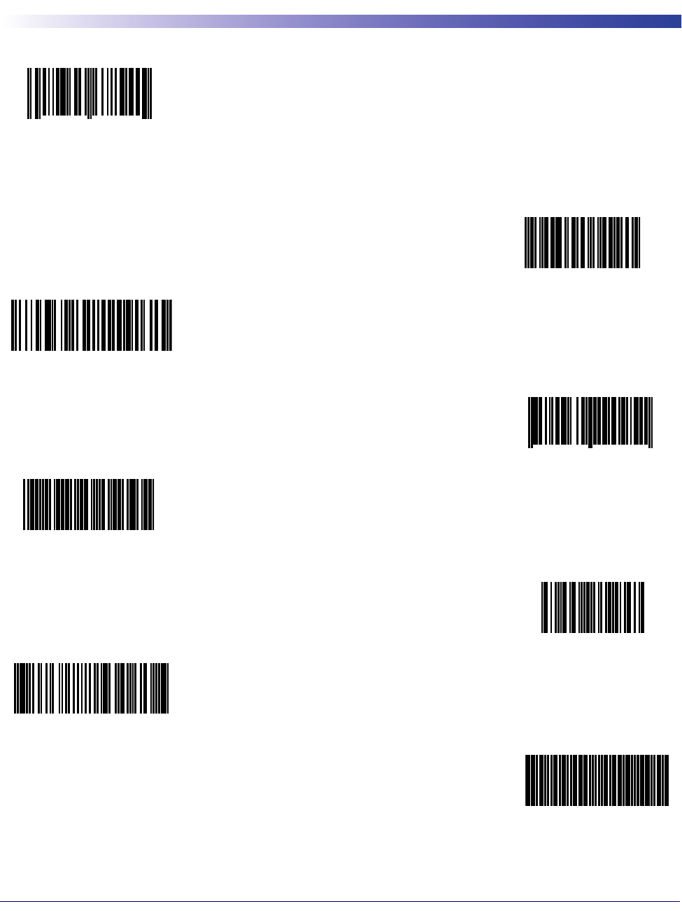
Product Reference Guide
G-1
Chapter G
Sample Symbols
0 1234567890
1234567890
Code 128
9 780330 290951
BC321
123456-9$
123456
UPC-A
Code 128
Code 39
Code 93
Interleaved 2 of 5
EAN-13
Code 2 of 5
A13579B
Codabar
05

G-2 Magellan
®
1000i
Sample Symbols
(01)00123456789012
GS1 DataBar Omni-
0100123456789050
GS1 DataBar Expanded

ASCII Chart
ASCII
Char. Hex No. ASCII
Char. Hex No. ASCII
Char. Hex No. ASCII
Char.
Hex
No.
NUL
SOH
STX
ETX
EOT
ENQ
ACK
BEL
BS
HT
LF
VT
FF
CR
SO
SI
DLE
DC1
DC2
DC3
DC4
NAK
SYN
ETB
CAN
EM
SUB
ESC
FS
GS
RS
US
00
01
02
03
04
05
06
07
08
09
0A
0B
0C
0D
0E
0F
10
11
12
13
14
15
16
17
18
19
1A
1B
1C
1D
1E
1F
SP
!
“
#
$
%
&
’
(
)
*
+
,
-
.
/
0
1
2
3
4
5
6
7
8
9
:
;
<
=
>
?
20
21
22
23
24
25
26
27
28
29
2A
2B
2C
2D
2E
2F
30
31
32
33
34
35
36
37
38
39
3A
3B
3C
3D
3E
3F
@
A
B
C
D
E
F
G
H
I
J
K
L
M
N
O
P
Q
R
S
T
U
V
W
X
Y
Z
[
\
]
^
_
40
41
42
43
44
45
46
47
48
49
4A
4B
4C
4D
4E
4F
50
51
52
53
54
55
56
57
58
59
5A
5B
5C
5D
5E
5F
‘
a
b
c
d
e
f
g
h
i
j
k
l
m
n
o
p
q
r
s
t
u
v
w
x
y
z
{
|
}
~
DEL
60
61
62
63
64
65
66
67
68
69
6A
6B
6C
6D
6E
6F
70
71
72
73
74
75
76
77
78
79
7A
7B
7C
7D
7E
7F

Australia
Datalogic Scanning Pty Ltd
Telephone: [61] (2) 9870 3200
australia.scanning@datalogic.com
France and Benelux
Datalogic Scanning Sarl
Telephone: [33].01.64.86.71.00
france.scanning@datalogic.com
Germany
Datalogic Scanning GmbH
Telephone: 49 (0) 61 51/93 58-0
germany.scanning@datalogic.com
India
Datalogic Scanning India
Telephone: 91- 22 - 64504739
india.scanning@datalogic.com
Italy
Datalogic Scanning SpA
Telephone: [39] (0) 39/62903.1
italy.scanning@datalogic.com
Japan
Datalogic Scanning KK
Telephone: 81 (0)3 3491 6761
japan.scanning@datalogic.com
Latin America
Datalogic Scanning, Inc
Telephone: (305) 591-3222
latinamerica.scanning@datalogic.com
Singapore
Datalogic Scanning Singapore PTE LTD
Telephone: (65) 6435-1311
singapore.scanning@datalogic.com
Spain and Portugal
Datalogic Scanning Sarl Sucursal en España
Telephone: 34 91 746 28 60
spain.scanning@datalogic.com
United Kingdom
Datalogic Scanning LTD
Telephone: 44 (0) 1923 809500
uk.scanning@datalogic.com
www.scanning.datalogic.com
Datalogic Scanning, Inc.
959 Terry Street
Eugene, OR 97402
USA
Telephone: (541) 683-5700
Fax: (541) 345-7140
©2005-2009 Datalogic Scanning, Inc. R44-2747 (Rev H) 6/09
