Datalogic Scanning Matrix 400 Users Manual
400 to the manual f25483fa-c98d-4c16-a9ba-88da1b61f0c0
2015-02-02
: Datalogic-Scanning Datalogic-Scanning-Matrix-400-Users-Manual-425487 datalogic-scanning-matrix-400-users-manual-425487 datalogic-scanning pdf
Open the PDF directly: View PDF ![]() .
.
Page Count: 142 [warning: Documents this large are best viewed by clicking the View PDF Link!]
- CONTENTS
- 1 RAPID CONFIGURATION
- STEP 1 – ASSEMBLE THE READER
- STEP 2 – CONNECT THE SYSTEM
- STEP 3 – MOUNT AND POSITION THE READER
- STEP 4 – FOCUS THE READER
- STEP 5 – CALIBRATE IMAGE DENSITY
- STEP 6 – X-PRESS™ CONFIGURATION
- STEP 7 – INSTALLING VISISET™ CONFIGURATION PROGRAM
- STEP 8 – CONFIGURATION USING SETUP WIZARD
- STEP 9 – TEST MODE
- ADVANCED READER CONFIGURATION
- 2 INTRODUCTION
- 3 INSTALLATION
- 4 CBX ELECTRICAL CONNECTIONS
- 5 MATRIX 400™ CONNECTOR ELECTRICAL CONNECTIONS
- 6 TYPICAL LAYOUTS
- 7 READING FEATURES
- 8 SOFTWARE CONFIGURATION
- 9 MAINTENANCE
- 10 TROUBLESHOOTING
- 11 TECHNICAL FEATURES
- GLOSSARY
- INDEX
- DECLARATION OF CONFORMITY

MATRIX 400™
Reference Manual

Datalogic Automation S.r.l.
Via S. Vitalino 13
40012 - Lippo di Calderara di Reno
Bologna - Italy
Matrix 400™ Reference Manual
Ed.: 12/2008
ALL RIGHTS RESERVED
Datalogic reserves the right to make modifications and improvements without prior notification.
Datalogic shall not be liable for technical or editorial errors or omissions contained herein, nor for
incidental or consequential damages resulting from the use of this material.
Product names mentioned herein are for identification purposes only and may be trademarks and or
registered trademarks of their respective companies.
Datalogic is a registered trademark of Datalogic S.p.A. in many countries and the Datalogic logo is a
trademark of Datalogic S.p.A.
Datalogic Automation S.r.l. 2007 - 2008
12/12/08

iii
CONTENTS
REFERENCES ............................................................................................................vi
Conventions................................................................................................................. vi
Reference Documentation........................................................................................... vi
Service and Support .................................................................................................... vi
Patents.........................................................................................................................vi
COMPLIANCE............................................................................................................vii
EMC Compliance.........................................................................................................vii
Power Supply...............................................................................................................vii
LED Class....................................................................................................................vii
CE Compliance............................................................................................................vii
FCC Compliance .........................................................................................................vii
HANDLING................................................................................................................viii
GENERAL VIEW..........................................................................................................x
1 RAPID CONFIGURATION ...........................................................................................1
Step 1 – Assemble the Reader.....................................................................................1
Step 2 – Connect the System.......................................................................................2
Step 3 – Mount and Position the Reader......................................................................5
Step 4 – Focus the Reader...........................................................................................6
Step 5 – Calibrate Image Density.................................................................................7
Step 6 – X-PRESS™ Configuration..............................................................................9
Step 7 – Installing VisiSet™ Configuration Program ..................................................11
Step 8 – Configuration Using Setup Wizard ...............................................................12
Step 9 – Test Mode ....................................................................................................18
Advanced Reader Configuration.................................................................................19
2 INTRODUCTION ........................................................................................................20
2.1 Product Description ....................................................................................................20
2.2 Indicators and Keypad Button.....................................................................................24
2.3 ID-NET™ ....................................................................................................................25
2.3.1 How To Setup/Configure the Reader Network ...........................................................26
2.4 X-PRESS™ Human Machine Interface ......................................................................28
2.4.1 X-PRESS™ Functions................................................................................................28
2.5 Model Description.......................................................................................................30
2.6 Accessories ................................................................................................................31
2.7 Application Examples .................................................................................................32
2.8 External Lighting Systems ..........................................................................................35
3 INSTALLATION .........................................................................................................39
3.1 Package Contents ......................................................................................................39
3.2 Mechanical Dimensions..............................................................................................40
3.3 Mounting and Positioning Matrix 400™......................................................................42
4 CBX ELECTRICAL CONNECTIONS.........................................................................44
4.1 Power Supply..............................................................................................................45
4.2 Main Serial Interface...................................................................................................45
4.2.1 RS232 Interface..........................................................................................................46
4.2.2 RS485 Full-Duplex Interface.......................................................................................47
4.2.3 RS485 Half-Duplex Interface......................................................................................48

iv
4.3 ID-NET™ Interface .....................................................................................................50
4.3.1 ID-NET™ Cables........................................................................................................50
4.3.2 ID-NET™ Response Time..........................................................................................51
4.3.3 ID-NET™ Network Termination..................................................................................55
4.4 Auxiliary RS232 Interface ...........................................................................................55
4.5 Inputs..........................................................................................................................56
4.6 Outputs .......................................................................................................................59
4.7 External Lighting Systems ..........................................................................................61
4.8 User Interface - Host...................................................................................................62
5 MATRIX 400™ CONNECTOR ELECTRICAL CONNECTIONS................................63
5.1 M16 19-Pin Connector................................................................................................63
5.2 M12-D 4-Pin Connector (Ethernet) .............................................................................64
5.3 Power Supply..............................................................................................................64
5.4 Main Serial Interface...................................................................................................64
5.4.1 RS232 Interface..........................................................................................................65
5.4.2 RS485 Full-Duplex Interface.......................................................................................66
5.4.3 RS485 Half-Duplex Interface......................................................................................67
5.5 ID-NET™ Interface .....................................................................................................69
5.5.1 ID-NET™ Cables........................................................................................................69
5.5.2 ID-NET™ Response Time..........................................................................................70
5.5.3 ID-NET™ Network Termination..................................................................................74
5.6 Auxiliary RS232 Interface ...........................................................................................74
5.7 Ethernet Interface (Matrix 400 XXX-010 models only) ...............................................75
5.8 Inputs..........................................................................................................................76
5.9 Outputs .......................................................................................................................79
5.10 User Interface .............................................................................................................81
6 TYPICAL LAYOUTS ..................................................................................................82
6.1 Point-to-Point..............................................................................................................82
6.2 Pass-Through .............................................................................................................84
6.3 ID-NET™ ....................................................................................................................86
6.4 RS232 Master/Slave...................................................................................................89
6.5 Multiplexer ..................................................................................................................90
6.6 Ethernet Connection (Matrix 400 XXX-010 models only) ...........................................91
7 READING FEATURES...............................................................................................93
7.1 Optical Accessory Selection .......................................................................................93
7.2 Horizontal FOV vs. Reading Distance Diagrams........................................................94
7.2.1 How to Use the Diagrams...........................................................................................94
7.2.2 1D (Linear) Codes ......................................................................................................95
7.2.3 2D (Bi-dimensional) Codes.........................................................................................97
7.3 Maximum Line Speed and Exposure Time Calculations ............................................99
8 SOFTWARE CONFIGURATION..............................................................................102
8.1 VisiSet™ System Requirements...............................................................................102
8.2 Installing VisiSet™....................................................................................................102
8.3 Startup ......................................................................................................................103
8.3.1 VisiSet™ Options......................................................................................................104
8.4 Configuration ............................................................................................................106
8.4.1 Edit Reader Parameters ...........................................................................................107
8.4.2 Send Configuration Options......................................................................................109
8.4.3 Calibration.................................................................................................................112
8.4.4 Multi Image Acquisition Settings...............................................................................116
8.4.5 Run Time Self Tuning (RTST) ..................................................................................116

v
8.4.6 Region Of Interest Windowing..................................................................................117
8.4.7 Direct Part Marking Applications...............................................................................118
8.5 Image Capture and Decoding...................................................................................120
8.6 Statistics ...................................................................................................................120
9 MAINTENANCE .......................................................................................................121
9.1 Cleaning....................................................................................................................121
10 TROUBLESHOOTING .............................................................................................122
10.1 General Guidelines...................................................................................................122
11 TECHNICAL FEATURES.........................................................................................125
GLOSSARY..............................................................................................................127
INDEX.......................................................................................................................130

vi
REFERENCES
CONVENTIONS
This manual uses the following conventions:
"User" refers to anyone using a Matrix 400™ reader.
"Reader" refers to the Matrix 400™ reader.
"You" refers to the System Administrator or Technical Support person using this manual to
install, configure, operate, maintain or troubleshoot a Matrix 400™ reader.
REFERENCE DOCUMENTATION
For further details refer to: the VisiSet™ Help On Line, Matrix Reading Methods, Matrix Host
Mode Programming, Matrix SW Parameter Guide, Matrix Code Quality Verifier Solution
provided as supplementary documentation on CD-ROM.
SERVICE AND SUPPORT
Datalogic provides several services as well as technical support through its website. Log on
to www.automation.datalogic.com and click on the links indicated for further information
including:
PRODUCTS
Search through the links to arrive at your product page where you can download specific
Manuals and Software & Utilities
- VisiSet™ a utility program, which allows device configuration using a PC. It provides
RS232 and Ethernet interface configuration.
SERVICES & SUPPORT
- Datalogic Services - Warranty Extensions and Maintenance Agreements
- Authorised Repair Centres
CONTACT US
E-mail form and listing of Datalogic Subsidiaries
PATENTS
This product is covered by one or more of the following patents:
U.S. patents: 6,512,218 B1; 6,616,039 B1; 6,808,114 B1; 6,997,385 B2; 7,102,116 B2;
7,282,688 B2
European patents: 999,514 B1; 1,014,292 B1; 1,128,315 B1.
Additional patents pending.

vii
COMPLIANCE
For installation, use and maintenance it is not necessary to open the reader.
EMC COMPLIANCE
In order to meet the EMC requirements:
connect reader chassis to the plant earth ground by means of a flat copper braid shorter
than 100 mm;
for CBX connections, connect the pin "Earth" to a good Earth Ground
for direct connections, connect the main interface cable shield to pin K of the 19-pin
connector;
POWER SUPPLY
ATTENTION: READ THIS INFORMATION BEFORE INSTALLING THE PRODUCT
This product is intended to be installed by Qualified Personnel only.
This product is intended to be connected to a UL Listed Computer which supplies power
directly to the reader or a UL Listed Direct Plug-in Power Unit marked LPS or “Class 2”, rated
10 to 30 V, minimum 1 A.
LED CLASS
Class 1 LED Product to EN60825-1:2001
CE COMPLIANCE
Warning: This is a Class A product. In a domestic environment this product may cause radio
interference in which case the user may be required to take adequate measures.
FCC COMPLIANCE
Modifications or changes to this equipment without the expressed written approval of Datalogic could
void the authority to use the equipment.
This device complies with PART 15 of the FCC Rules. Operation is subject to the following two
conditions: (1) This device may not cause harmful interference, and (2) this device must accept any
interference received, including interference which may cause undesired operation.
This equipment has been tested and found to comply with the limits for a Class A digital device,
pursuant to part 15 of the FCC Rules. These limits are designed to provide reasonable protection
against harmful interference when the equipment is operated in a commercial environment. This
equipment generates, uses, and can radiate radio frequency energy and, if not installed and used in
accordance with the instruction manual, may cause harmful interference to radio communications.
Operation of this equipment in a residential area is likely to cause harmful interference in which case
the user will be required to correct the interference at his own expense.

viii
HANDLING
The Matrix 400™ is designed to be used in an industrial environment and is built to withstand
vibration and shock when correctly installed, however it is also a precision product and
therefore before and during installation it must be handled correctly to avoid damage.
avoid that the readers are dropped (exceeding shock limits).
do not fine tune the positioning by striking the reader or bracket.

ix
do not weld the reader into position which can cause electrostatic, heat or reading
window damage.
do not spray paint near the reader which can cause reading window damage.
x
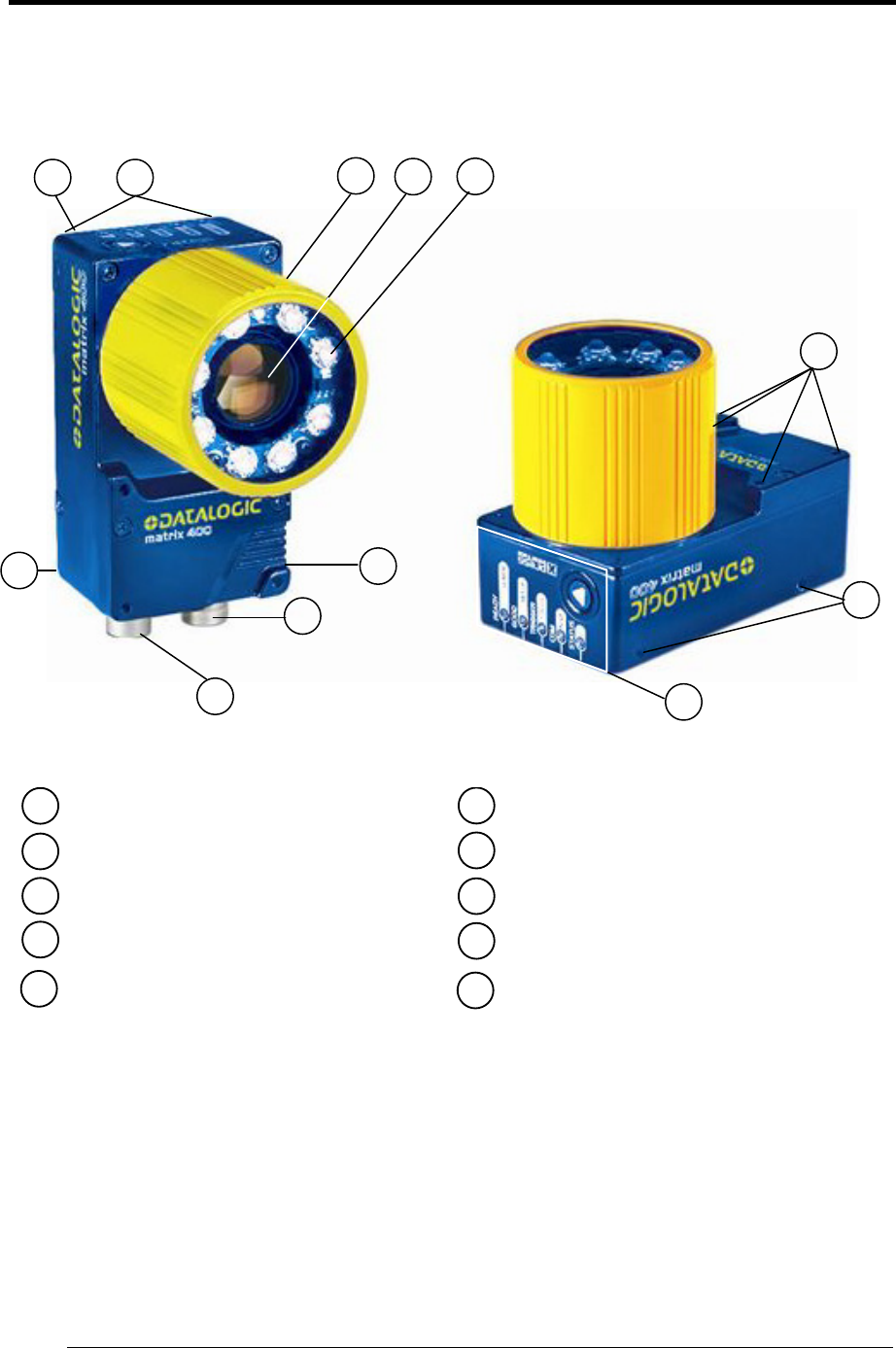
GENERAL VIEW
Matrix 400™
Figure A
1
2
3
4 9
8
7
Device Class Label
Mounting Holes (12)
Lens Cover
Lens (separate accessory)
"POWER ON" LED
Power - Serial Interfaces - I/O Connector
Ethernet Connector (Ethernet Models Only)
6HMI X-PRESS™ Interface
5 Internal Illuminator (separate accessory) Ethernet Connection LED
(Ethernet Models Only)
10
7
1 3 4 5
2
6
8
9
10
2
2
RAPID CONFIGURATION
1
1
1 RAPID CONFIGURATION
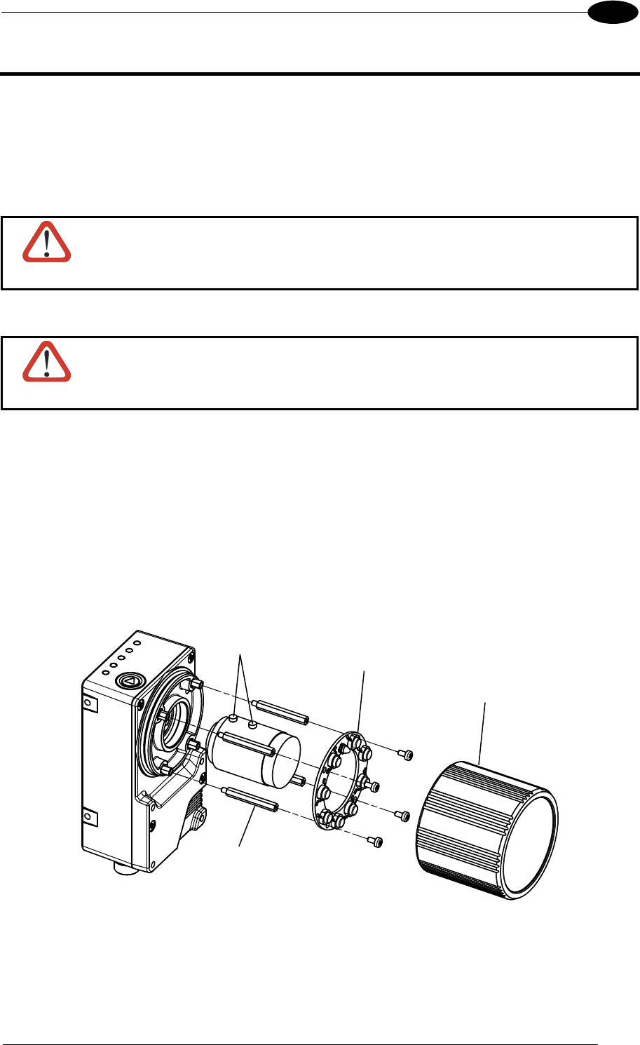
STEP 1 – ASSEMBLE THE READER
The first step to perform is to assemble the accessories that make up the Matrix 400™
reader. The lens and either an internal or an external illuminator must be used. This
procedure shows an internal illuminator.
CAUTION
Matrix 400™ must be disconnected from the power supply during this
procedure.
1. In a dust-free environment, remove the Matrix 400™ Lens Cover by unscrewing it.
CAUTION
Do not touch the sensor aperture, lens glass or lens cover glass. These
areas must be kept clean. Avoid any abrasive substances that might damage
these surfaces during cleaning.
2. Remove the sensor protection label by pulling it off of the base.
3. Mount the lens by screwing it tightly onto the base.
4. If using an internal illuminator:
a. Mount the 4 internal illuminator spacers into the holes provided on the base.
b. Align and mount the Illuminator board tightly onto the spacers using the 4 screws
provided in the illuminator package. The spacers are positioned asymmetrically to
avoid incorrect alignment.
5. To keep dust and dirt off of the lens during mounting, temporarily replace the lens cover.
Figure 1 – Assembling Matrix 400™ Accessories
Locking Knobs Internal
Illuminator
Lens Cover
Illuminator Spacers
MATRIX 400™ REFERENCE MANUAL
2
1
Required Accessories
The following table shows the correct lens/illuminator combinations to be used for Matrix
400™ imager assembly.
Lenses Internal Illuminators
93ACC1793 LNS-1006 6 mm C-Mount Lens
(only for Matrix 400 600-0x0 models)
93A401020
93A401022
LT-002
LT-004
Red Wide Angle
White Wide Angle
93ACC1794 LNS-1109 9 mm C-Mount Lens 93A401020
93A401022
LT-002
LT-004
Red Wide Angle
White Wide Angle
93ACC1795 LNS-1112 12.5 mm C-Mount Lens 93A401020
93A401022
LT-002
LT-004
Red Wide Angle
White Wide Angle
93ACC1796 LNS-1116 16 mm C-Mount Lens 93A401019
93A401021
LT-001
LT-003
Red Narrow Angle
White Narrow Angle
93ACC1797 LNS-1125 25 mm C-Mount Lens 93A401019
93A401021
LT-001
LT-003
Red Narrow Angle
White Narrow Angle
93ACC1798 LNS-1135 35 mm C-Mount Lens 93A401024 LT-006 Red Super Narrow Angle
93ACC1799 LNS-1150 50 mm C-Mount Lens 93A401024 LT-006 Red Super Narrow Angle
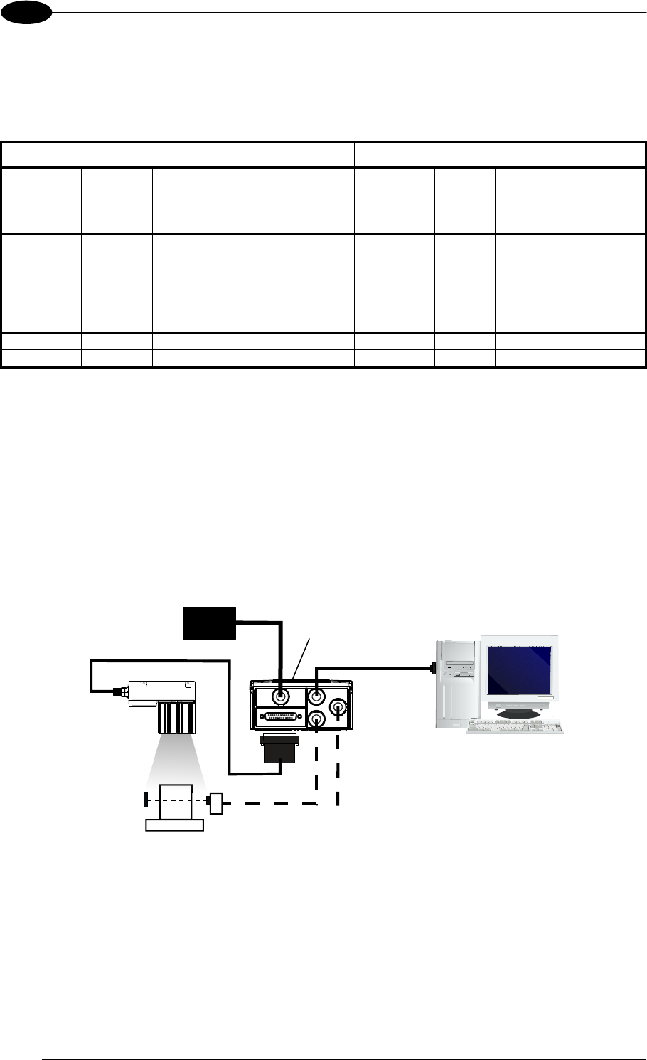
STEP 2 – CONNECT THE SYSTEM
To connect the system in a Stand Alone configuration, you need the hardware indicated in
Figure 2. In this layout the data is transmitted to the Host on the main serial interface. Data
can also be transmitted on the RS232 auxiliary interface independently from the main
interface selection.
When One Shot or Phase Mode Operating mode is used, the reader is activated by an
External Trigger (photoelectric sensor) when the object enters its reading zone.
Figure 2 – Matrix 400™ in Stand Alone Layout
Matrix 400™
Host
PG 6000
P.S.** External Trigger or Presence Senso
r
(for One Shot or Phase Mode)
CBX
Main Interface
CAB-MS01
I/O, AUX
RAPID CONFIGURATION
3
1
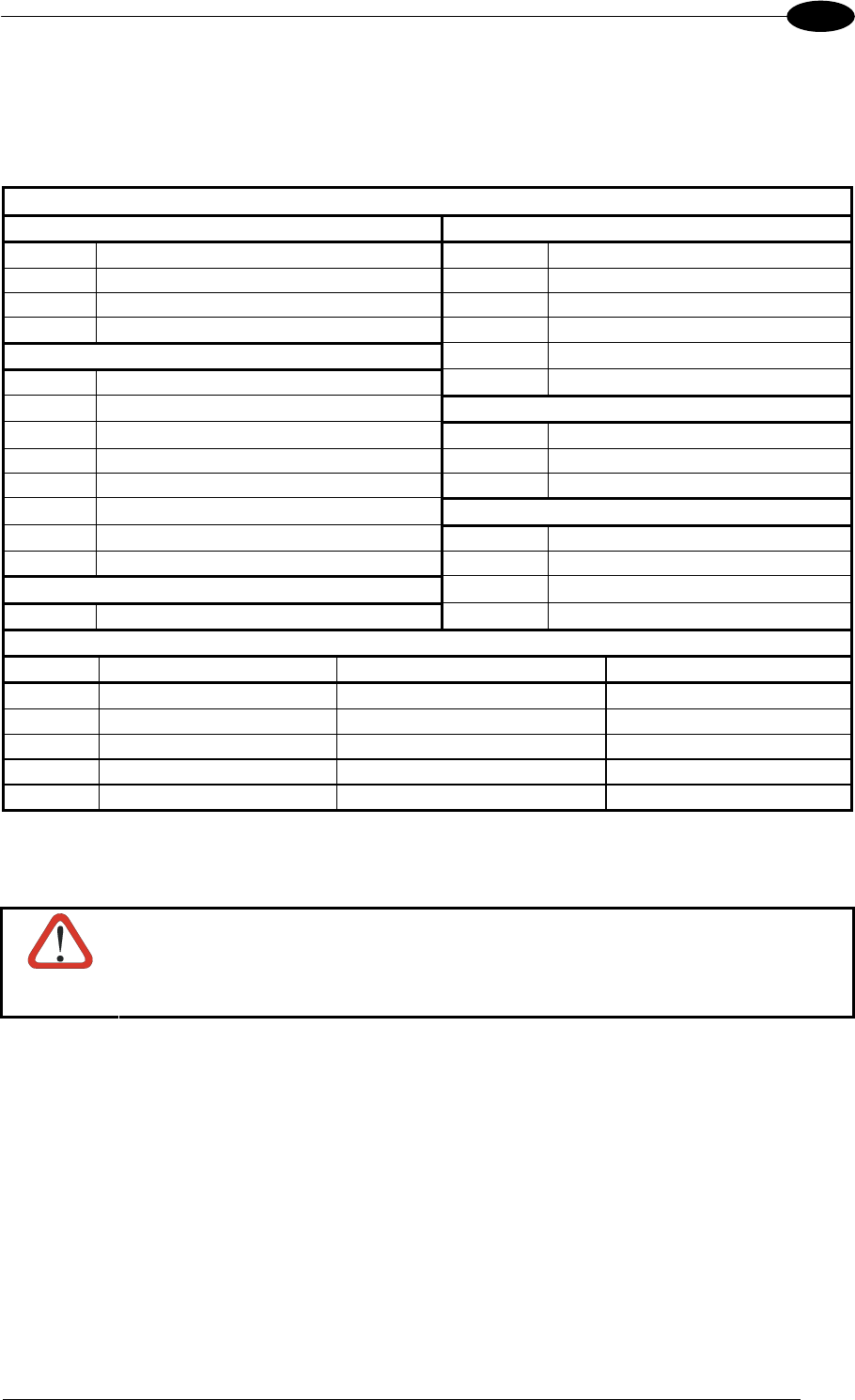
CBX100/CBX500 Pinout for Matrix 400™
The table below gives the pinout of the CBX100/CBX500 terminal block connectors. Use this
pinout when the Matrix 400™ reader is connected by means of the CBX100/CBX500:
CBX100/500 Terminal Block Connectors
Input Power Outputs
Vdc Power Supply Input Voltage + +V Power Source - Outputs
GND Power Supply Input Voltage - -V Power Reference - Outputs
Earth Protection Earth Ground O1+ Output 1 +
O1- Output 1 -
Inputs O2+ Output 2 +
+V Power Source – External Trigger O2- Output 2 -
I1A External Trigger A (polarity insensitive) Auxiliary Interface
I1B External Trigger B (polarity insensitive) TX Auxiliary Interface TX
-V Power Reference – External Trigger RX Auxiliary Interface RX
+V Power Source – Inputs SGND Auxiliary Interface Reference
I2A Input 2 A (polarity insensitive) ID-NET™
I2B Input 2 B (polarity insensitive) REF Network Reference
-V Power Reference – Inputs ID+ ID-NET™ network +
Shield ID- ID-NET™ network -
Shield Network Cable Shield
Main Interface
RS232 RS485 Full-Duplex RS485 Half-Duplex
TX TX+ RTX+
RTS TX- RTX-
RX *RX+
CTS *RX-
SGND SGND SGND
* Do not leave floating, see par. 4.2.2 for connection details.
CAUTION
Do not connect GND, SGND and REF to different (external) ground
references. GND, SGND and REF are internally connected through filtering
circuitry which can be permanently damaged if subjected to voltage drops
over 0.8 Vdc.
MATRIX 400™ REFERENCE MANUAL
4
1
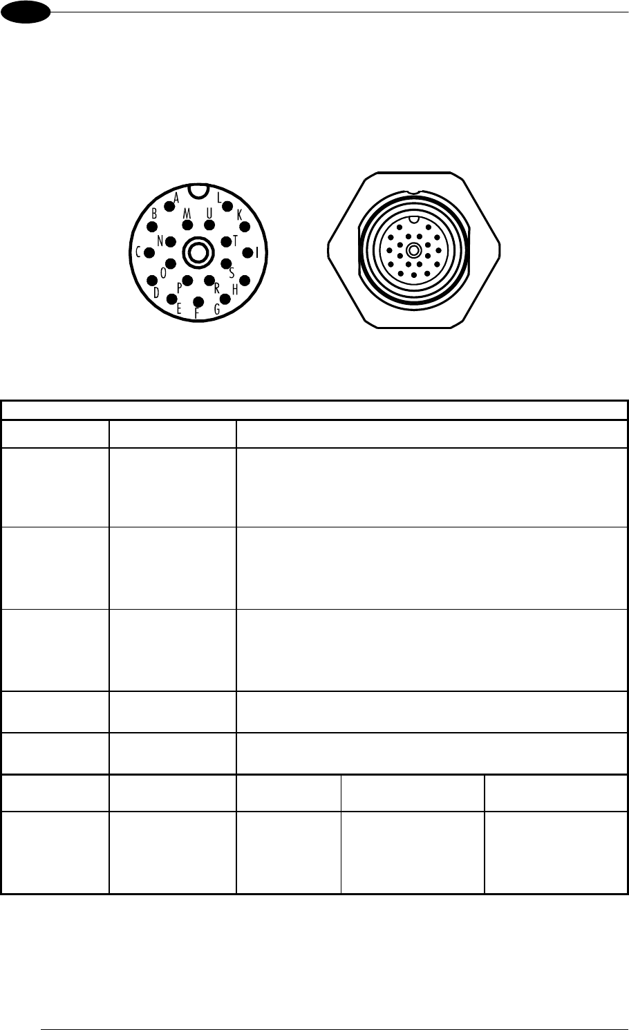
19-pin Connector Pinout for Matrix 400™
The table below gives the pinout of the 19-pin M16 male connector for connection to the
power supply and input/output signals. Use this pinout when the Matrix 400™ reader is
connected by means of the 19-pin connector:
Figure 3 - 19-pin M16 Male Connector
19-pin M16 male connector pinout
Pin Name Function
A Vdc Power supply input voltage +
L GND Power supply input voltage -
K CHASSIS Cable shield internally connected by capacitor to the
chassis
B I1A External Trigger A (polarity insensitive)
C I1B External Trigger B (polarity insensitive)
D I2A Input 2 A (polarity insensitive)
E I2B Input 2 B (polarity insensitive)
H O1+ Output 1 +
F O1- Output 1 -
G O2+ Output 2 +
I O2- Output 2 -
S RX Auxiliary RS232 RX
O TX Auxiliary RS232 TX
R ID+ ID-NET™ network +
P ID- ID-NET™ network -
Pin Name RS232
RS485
Full-Duplex
RS485
Half-Duplex
M TX TX+ RTX+
U RX *RX+
N RTS TX- RTX-
T
MAIN
INTERFACE
(SW
SELECTABLE) CTS *RX-
* Do not leave floating, see par. 5.4.2 for connection details.
RAPID CONFIGURATION
5
1
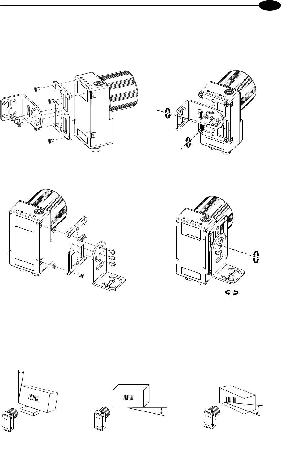
STEP 3 – MOUNT AND POSITION THE READER
1. To mount the Matrix 400™, use the mounting brackets to obtain the most suitable
position for the reader. Two of the most common mounting configurations are shown in
the figures below. Other mounting solutions are provided in par. 3.3.
Figure 4 –Positioning with Mounting Bracket (Back)
Figure 5 –Positioning with Mounting Bracket (Side)
2. When mounting the Matrix 400™ take into consideration these three ideal label position
angles: Pitch or Skew 10° to 20° and Tilt 0°, although the reader can read a code at any tilt
angle.
P
S
T
Minimize Assure at least 10° Minimize
Figure 6 – Pitch, Skew and Tilt Angles
Tilt
Pitch
Skew
Pitch
MATRIX 400™ REFERENCE MANUAL
6
1
3. Refer to the Reading Features table in chp. 7 for FOV calculation and minimum
distance requirements according to the base/lens combination used for your
application.
NOTE
Rapid Configuration of the Matrix 400™ reader can be made either through
the X-PRESS™ interface (steps 4-6) which requires no PC connection, or by
using the VisiSet™ Setup Wizard (steps 7-8). Select the procedure according
to your needs.
STEP 4 – FOCUS THE READER
Matrix 400™ provides a built-in tool called Blue Diamonds™ to aid focusing the reader. The
Blue Diamonds™ are accessed through the X-PRESS™ Interface.
1. Remove the lens cover in order to focus the reader.
2. Prepare the correct accessory lens for your application:
a. Loosen the two Locking Knobs on the lens.
b. Adjust the Focus ring to the "Far position" and the Diaphragm ring to the "F4"1
number setting which is the preferred setting for installation.
3. Power the reader on. During the reader startup (reset or restart phase), all the LEDs blink
for one second. On the connector side of the reader near the cable, the “POWER ON”
LED (blue) indicates the reader is correctly powered.
4. Enter the Focus function by pressing and holding the X-PRESS™ push button until the
Focus LED is on.
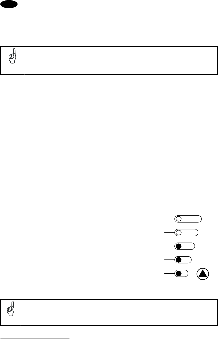
5. Release the button to enter the Focus function. The Blue Diamonds™ turn on.
The procedure is as follows:
A) Adjust the Focus ring towards the "Near position" until
the Blue Diamonds™ are perfectly in focus, see
Figure 8.
At long focal distances a "skew" angle may cause a
noticeable difference in focus between the two
diamonds, in this case select the best possible focus
(both diamonds slightly out of focus).
Tighten the Focus Locking Knob.
B) Tighten the Diaphragm Locking Knob.
READ
Y
green
green
y
ellow
y
ellow
red
SETUP
FOCUS
T
ES
T
LEARN
GOOD
T
RIGGER
COM
STATUS
Figure 7 – X-PRESS™ Interface:
Focus Function
NOTE
If necessary you can use the Fine Focusing Tool in the VisiSet™ Setup Wizard
for fine focusing. See Step 8.
1 For far reading distances, the Diaphragm ring can be set to values between F2 and F4 to increase image lighting and Blue
Diamond™ visibility.
RAPID CONFIGURATION
7
1
FOV
Blue Diamond™
in focus
Figure 8 – Focus Function Using Blue Diamonds™
6. Exit the Focus function by pressing the X-PRESS™ push button once. The Blue
Diamonds™ turn off.
7. Replace the lens cover, screwing it tightly to the base.
STEP 5 – CALIBRATE IMAGE DENSITY
In order to function correctly to the fullest extent of its capabilities, Matrix 400™ must acquire
information regarding image density or PPI (pixels per inch). This calibration takes place
through the X-PRESS™ Interface and the Grade A Barcode Test Chart included in the
package. This procedure is necessary for the first time installation, if the lens type is changed
or if the focal distance is changed.
Locate
1. Enter the Focus function by pressing and holding the
X-PRESS™ push button until the Focus LED is on.
2. Release the button to enter the Focus function. The
Blue Diamonds™ turn on.
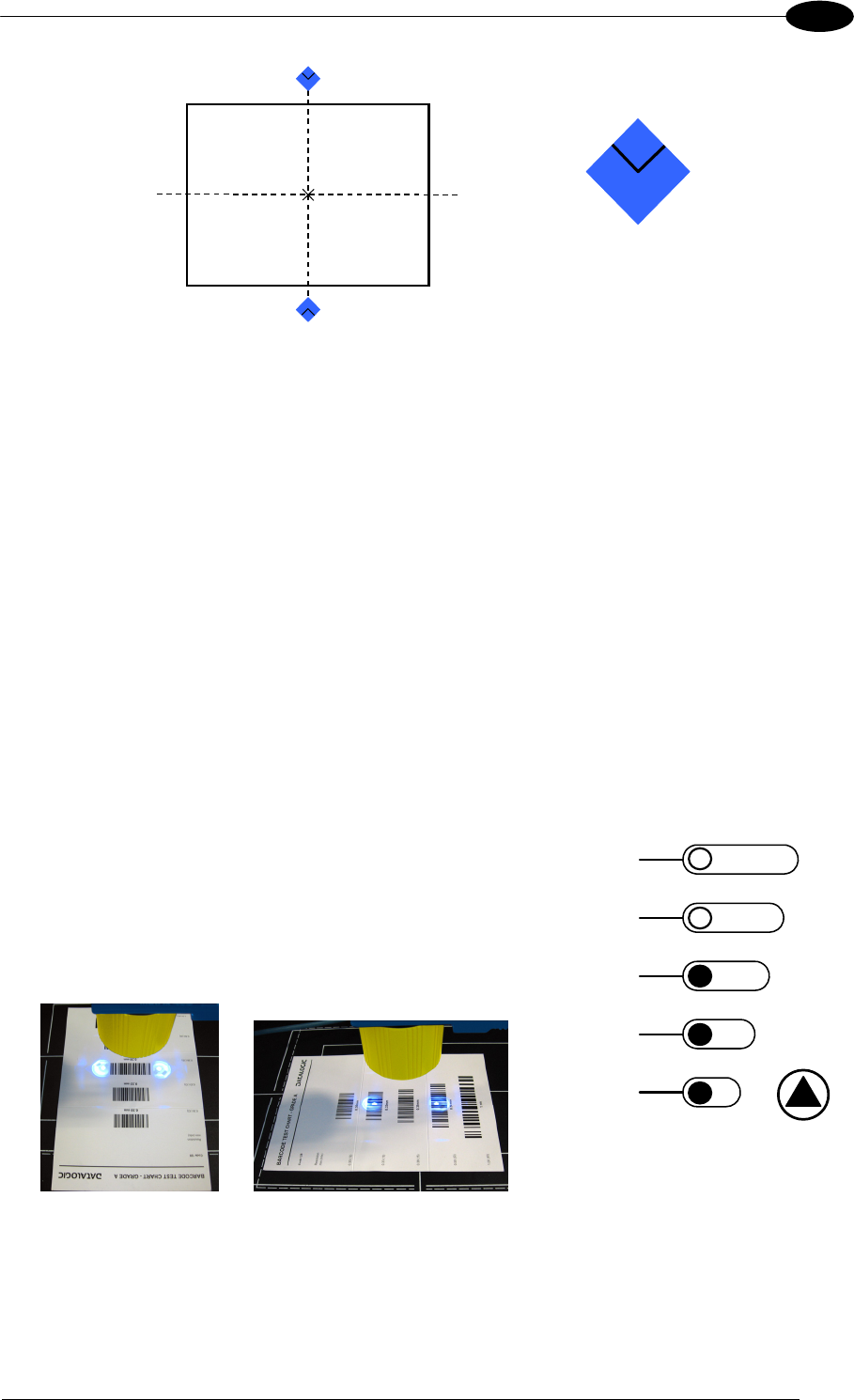
3. From the Grade A Barcode Test Chart, select the
longest code whose length fits between the two Blue
Diamonds™. Rotate the code 90 degrees and
position the code at the center of the FOV
(equidistant from the Blue Diamonds™).
4. Exit the Focus function by pressing the X-PRESS™
push button once. The Blue Diamonds™ turn off.
READY
g
reen
g
reen
y
ellow
y
ellow
red
SETUP
FOCUS
T
ES
T
LEARN
GOOD
T
RIGGER
COM
STATUS
Figure 9 – X-PRESS™ Interface:
Locate Function
MATRIX 400™ REFERENCE MANUAL
8
1
Setup
5. Enter the Setup function by pressing and holding the
X-PRESS™ push button until the Setup LED is on.
6. Release the button to enter the Setup function. The
Setup LED will blink until the procedure is
completed.
The Setup procedure ends when the Image
Acquisition parameters are successfully saved in the
reader memory, the Setup LED will remain on
continuously and Matrix 400™ emits 3 high pitched
beeps.
If the calibration cannot be reached after a timeout of
about 5 (five) seconds Matrix 400™ will exit without
saving the parameters to memory, the Setup LED will
not remain on continuously but it will just stop
blinking. In this case Matrix 400™ emits a long low
pitched beep.
7. Exit the Setup function by pressing the X-PRESS™
push button once.
READY
green
green
y
ellow
y
ellow
red
SETUP
FOCUS
T
ES
T
LEARN
GOOD
T
RIGGER
COM
STATUS
Figure 10 – X-PRESS™ Interface:
Setup Function
Learn
8. Enter the Learn function by pressing and holding the
X-PRESS™ push button until the Learn LED is on.
9. Release the button to enter the Learn function. The
Learn LED will blink until the procedure is
completed.
The Learn procedure ends when the Image Density
value is successfully saved in the reader memory,
the Learn LED will remain on continuously, the
Green Spot is activated and Matrix 400™ emits 3
high pitched beeps.
If the calibration cannot be reached after a timeout of
about 3 (three) minutes Matrix 400™ will exit without
saving the parameters to memory, the Learn LED will
not remain on continuously but it will just stop
blinking. In this case Matrix 400™ emits a long low
pitched beep.
10. Exit the Setup function by pressing the X-PRESS™
push button once.
READY
g
reen
g
reen
y
ellow
y
ellow
red
SETUP
FOCUS
T
ES
T
LEARN
GOOD
T
RIGGER
COM
STATUS
Figure 11 – X-PRESS™ Interface:
Learn Function
RAPID CONFIGURATION
9
1
STEP 6 – X-PRESS™ CONFIGURATION
Once Matrix 400™ has calibrated image density, you can configure it for optimal code
reading relative to your application. This configuration can be performed either through the X-
PRESS™ Interface or the VisiSet™ configuration program.
Locate
1. Enter the Focus function by pressing and holding
the X-PRESS™ push button until the Focus LED
is on.
2. Release the button to enter the Focus function.
The Blue Diamonds™ turn on.
3. Select a code from your application. Position
the code at the center of the FOV (equidistant from
the Blue Diamonds™).
4. Exit the Focus function by pressing the X-
PRESS™ push button once. The Blue
Diamonds™ turn off.
READY
g
reen
g
reen
y
ellow
y
ellow
red
SETUP
FOCUS
T
ES
T
LEARN
GOOD
T
RIGGER
COM
STATUS
Figure 12 – X-PRESS™ Interface:
Locate Function
Setup
5. Enter the Setup function by pressing and holding
the X-PRESS™ push button until the Setup LED is
on.
6. Release the button to enter the Setup function.
The Setup LED will blink until the procedure is
completed.
The Setup procedure ends when the Image
Acquisition parameters are successfully saved in
the reader memory, the Setup LED will remain on
continuously and Matrix 400™ emits 3 high pitched
beeps.
If the calibration cannot be reached after a timeout
of about 5 (five) seconds Matrix 400™ will exit
without saving the parameters to memory, the
Setup LED will not remain on continuously but it will
just stop blinking. In this case Matrix 400™ emits a
long low pitched beep.
7. Exit the Setup function by pressing the X-
PRESS™ push button once.
READY
green
green
y
ellow
y
ellow
red
SETUP
FOCUS
T
ES
T
LEARN
GOOD
T
RIGGER
COM
STATUS
Figure 13 – X-PRESS™ Interface:
Setup Function

MATRIX 400™ REFERENCE MANUAL
10
1
Learn
8. Enter the Learn function by pressing and holding
the X-PRESS™ push button until the Learn LED is
on.
9. Release the button to enter the Learn function.
The Learn LED will blink until the procedure is
completed.
The Learn procedure ends when the Image
Processing and Decoding parameters are
successfully saved in the reader memory, the
Learn LED will remain on continuously, the Green
Spot is activated and Matrix 400™ emits 3 high
pitched beeps.
If the calibration cannot be reached after a timeout
of about 3 (three) minutes Matrix 400™ will exit
without saving the parameters to memory, the
Learn LED will not remain on continuously but it will
just stop blinking. In this case Matrix 400™ emits a
long low pitched beep.
10. Exit the Setup function by pressing the X-
PRESS™ push button once.
READY
green
green
y
ellow
y
ellow
red
SETUP
FOCUS
T
ES
T
LEARN
GOOD
T
RIGGER
COM
STATUS
Figure 14 – X-PRESS™ Interface:
Learn Function
If you have used this procedure to configure Matrix 400™ go to step 9.
RAPID CONFIGURATION
11
1
STEP 7 – INSTALLING VISISET™ CONFIGURATION PROGRAM
VisiSet™ is a Datalogic reader configuration tool providing several important advantages:
Setup Wizard for rapid configuration and new users;
Defined configuration directly stored in the reader;
Communication protocol independent from the physical interface allowing to consider the
reader as a remote object to be configured and monitored.
To install VisiSet™, turn on the PC that will be used for the configuration, running
Windows 98, 2000/NT, XP or Vista, then insert the VisiSet™ CD-ROM, wait for the CD to
autorun and follow the installation procedure.
This configuration procedure assumes a laptop computer, running VisiSet™, is connected to
the reader's auxiliary port.
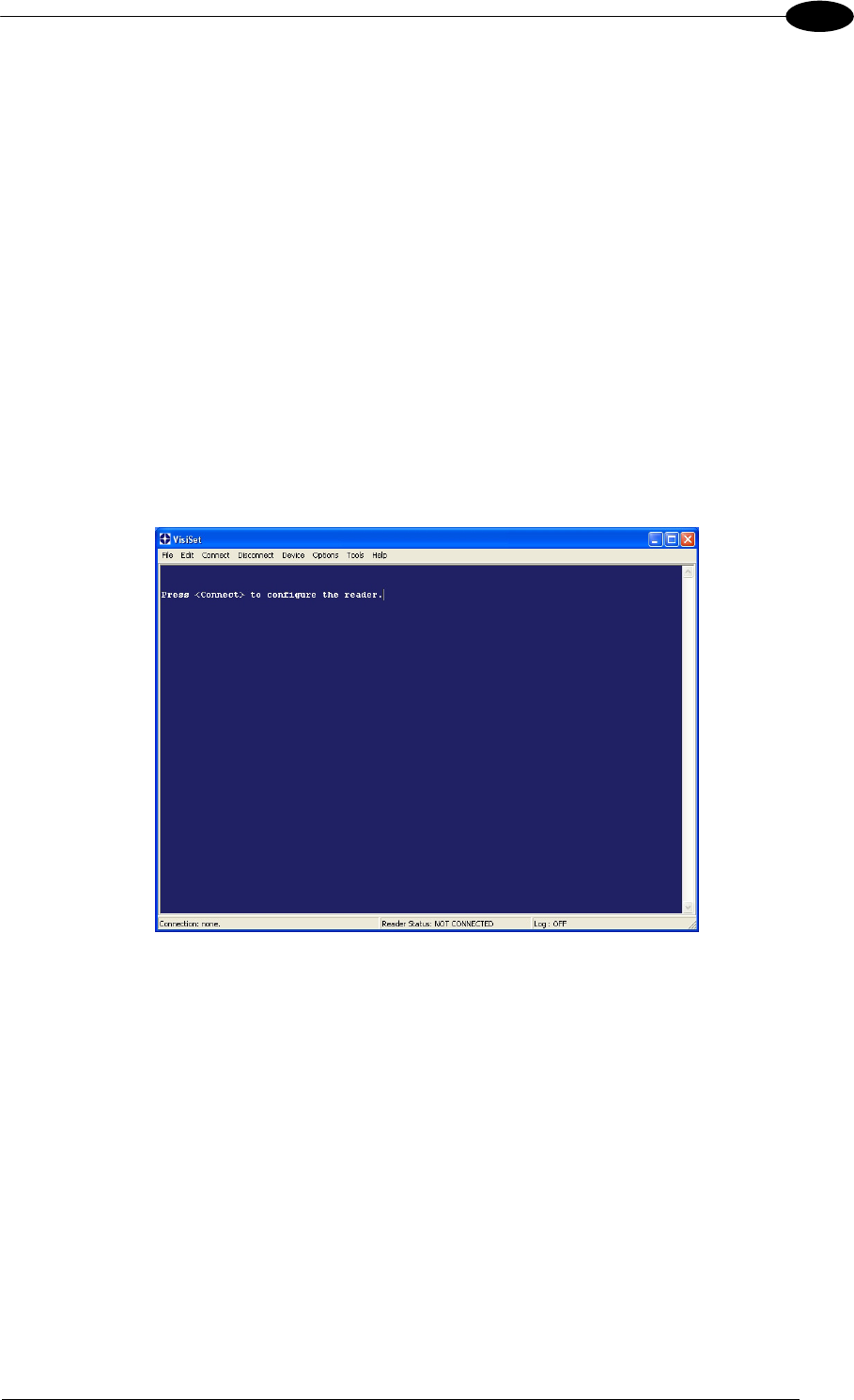
After installing and running the VisiSet™ software program the following window:
Figure 15 - VisiSet™ Opening Window
MATRIX 400™ REFERENCE MANUAL
12
1
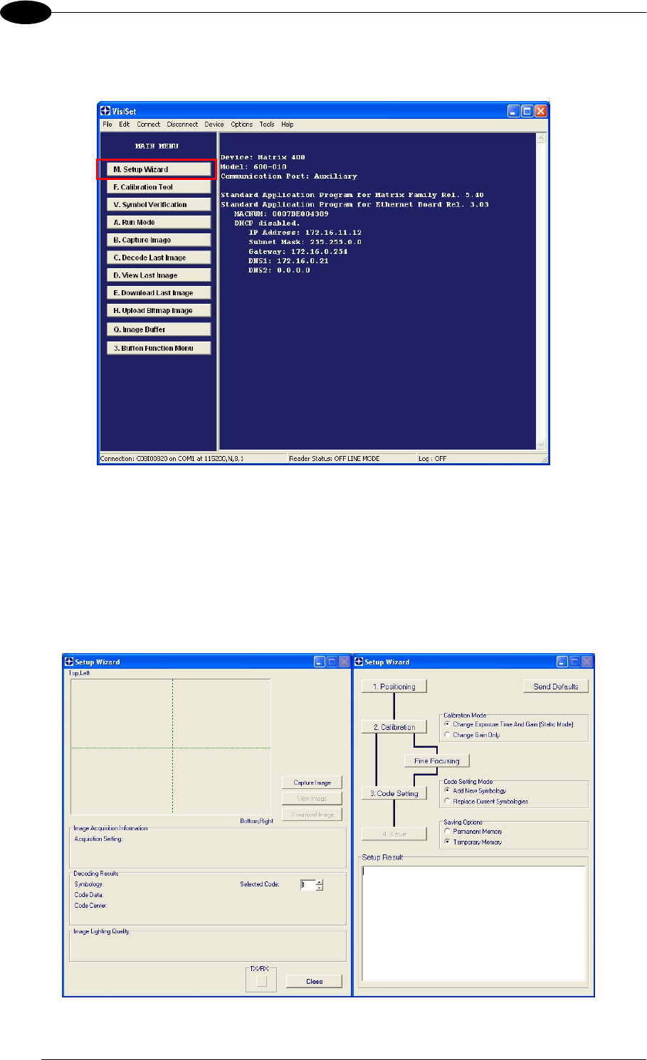
Set the communication parameters from the "Options" menu. Then select "Connect", the
following window appears:
Figure 16 - VisiSet™ Main Window After Connection
STEP 8 – CONFIGURATION USING SETUP WIZARD
The Setup Wizard option is advised for rapid configuration or for new users. It allows reader
configuration in a few easy steps.
1. Select the Setup Wizard button from the Main menu.
RAPID CONFIGURATION
13
1
2. Remove the lens cover in order to focus the reader and loosen the two Locking Knobs on
the lens.
Adjust the Focus ring to the "Far position" and the Diaphragm ring to the "F4"2 number
setting which is the preferred setting for installation.
Place the Grade A Barcode Test Chart in front of the reader at the correct reading
distance (see step 3 and the Optical Accessory Selection table in the par. 7.1).
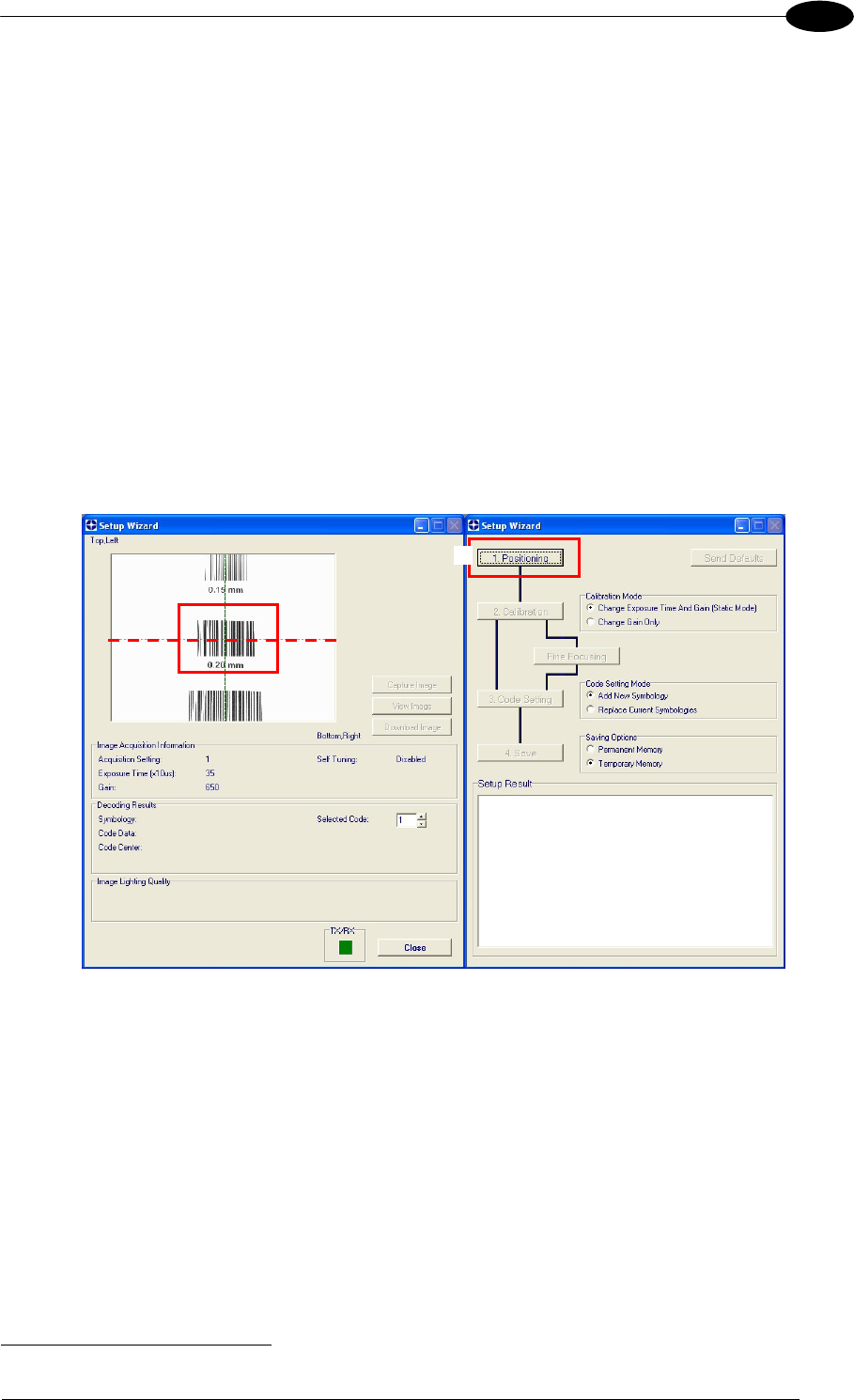
3. Press the "Positioning" button. The reader continuously acquires images and gives visual
feedback in the view image window. Select the largest code from the chart that
completely fits into the view image window. Move the reader (or code) to center it. The
code must be aligned across the X-axis reference line at the center of the FOV. See
figure below.
Press the Positioning button again to stop positioning.
2 For far reading distances, the Diaphragm ring can be set to values between F2 and F4 to increase image lighting.
3
MATRIX 400™ REFERENCE MANUAL
14
1
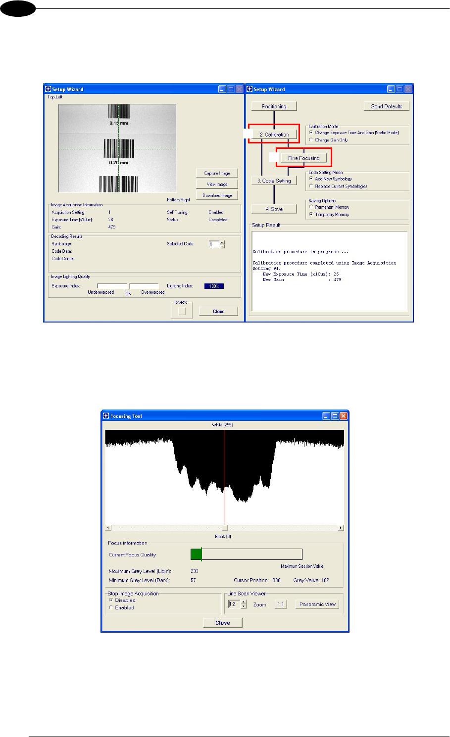
4. Select a Calibration Mode choice and press the "Calibrate" button. The reader flashes
once acquiring the image and auto determines the best exposure and gain settings. If the
code symbology is enabled by default, the code will also be decoded.
5. Press the "Fine Focusing" button to activate the Fine Focusing Tool.
The reader continuously acquires images and gives visual feedback on the focusing
quality in the Focusing Tool window.
Rotate the Focusing ring on the lens. The Current Focus Quality Bar (green) together
with the vertical optimal focus line (green) increase together until the optimal focus is
reached; the vertical optimal focus line stops.
4
5
RAPID CONFIGURATION
15
1
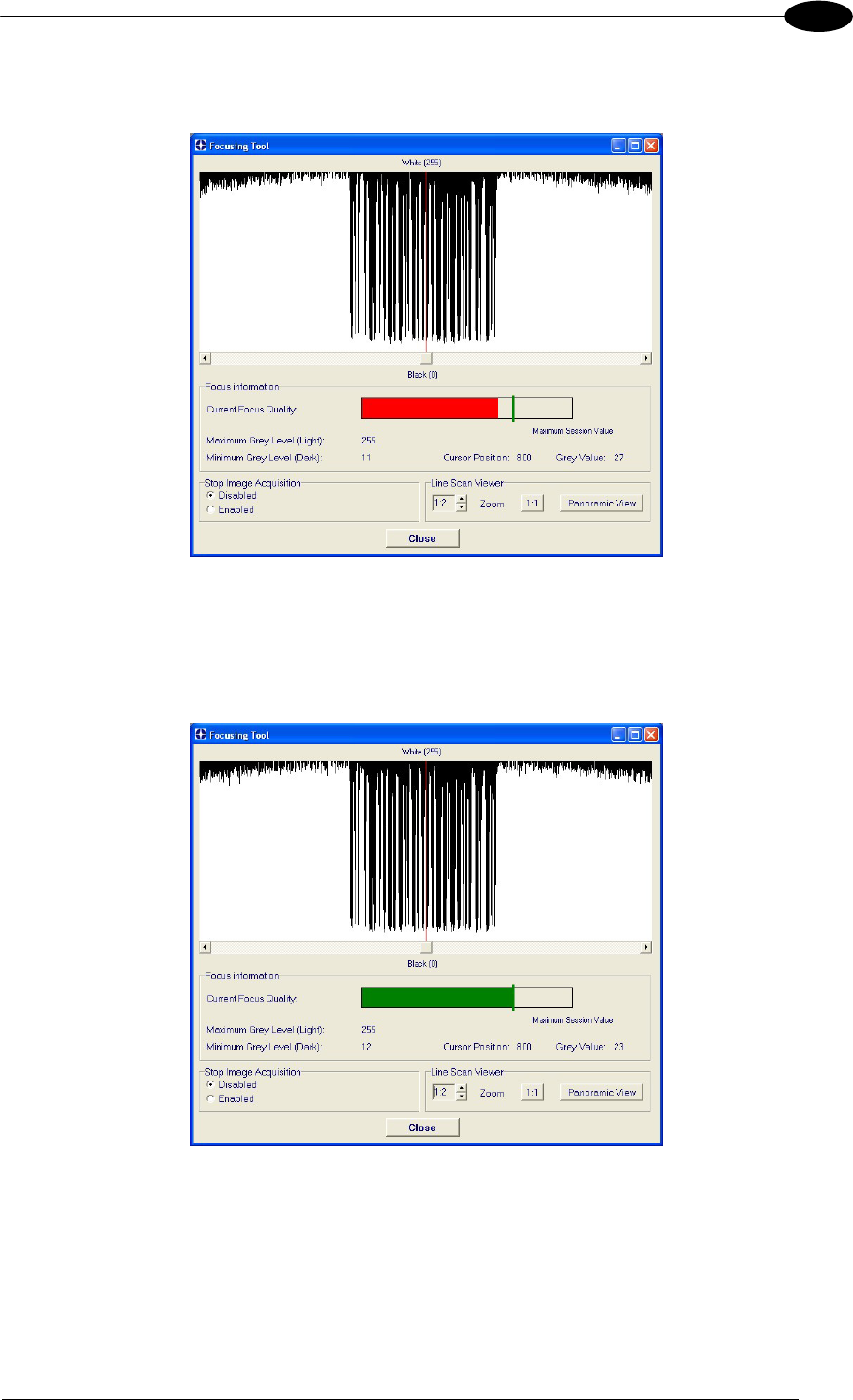
Continue rotating the Focusing ring on the lens a little farther; the Current Focus
Quality Bar decreases (red) see below.
Rotate the Focusing ring in the opposite direction. The Current Focus Quality Bar (green)
increases towards the vertical optimal focus line (green) until the optimal focus is
reached; the Current Focus Quality Bar touches the vertical optimal focus line
(indicating the best focus).
Tighten the Locking Knobs on the lens and press the "Close" button to return to the
Setup Wizard.
MATRIX 400™ REFERENCE MANUAL
16
1
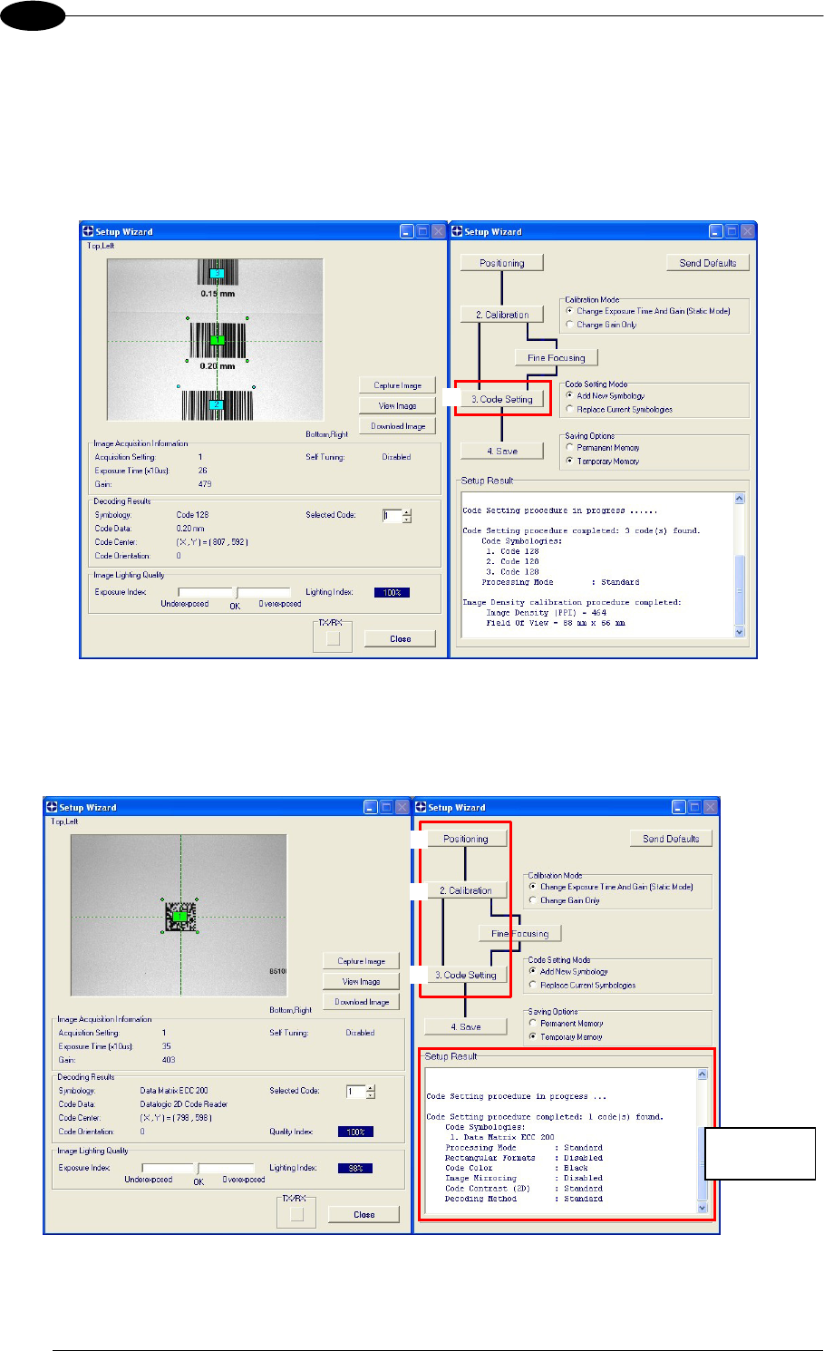
6. Select a Code Setting Mode choice and press the "Code Setting" button.
Using the Grade A Barcode Test Chart, this step performs image density calibration in
order for Matrix 400™ to function correctly and to the fullest extent of its capabilities.
The Setup Result section of the Setup Wizard window shows the code type results and
the image density calibration settings.
7. Place the application specific code in front of the reader at the same reading distance
and repeat steps 3, 4, and 6.
6
Setup Result
3
4
6
RAPID CONFIGURATION
17
1
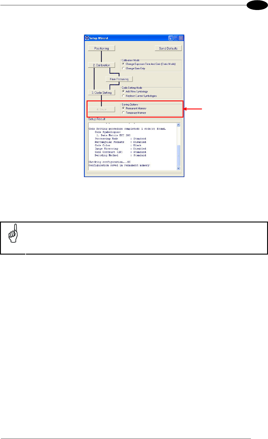
8. Select a Saving Options choice and press the "Save" button.
9. Close the Setup Wizard.
NOTE
If your application has been configured using the VisiSet™ Setup Wizard, your
reader is ready. If necessary you can use VisiSet™ for advanced reader
configuration.
MATRIX 400™ REFERENCE MANUAL
18
1
STEP 9 – TEST MODE
Use a code suitable to your application to test the reading performance of the system.
1. Enter the Test function by pressing and holding the X-PRESS™ push button until the
Test LED is on.
2. Release the button to enter the Test function.
Once entered, the Bar Graph on the five LEDs is activated and if the reader starts
reading codes the Bar-Graph shows the Good Read Rate. In case of no read condition,
only the STATUS LED is on and blinks.
READY
green
green
y
ellow
y
ellow
red
SETU
P
FOCUS
T
ES
T
LEARN
GOOD
T
RIGGER
COM
STATUS
Figure 17 – X-PRESS™ Interface: Test Function
3. To exit the Test, press the X-PRESS™ push button once.
NOTE
By default, the Test exits automatically after three minutes.
The Bar Graph has the following meaning:
READY
95%
75%
60%
40%
20%
SETUP
FOCUS
T
ES
T
LEARN
GOOD
T
RIGGER
COM
STATUS
RAPID CONFIGURATION
19
1
ADVANCED READER CONFIGURATION
For further details on advanced product configuration, refer to the VisiSet™ Help On-Line.
The following are alternative or advanced reader configuration methods:
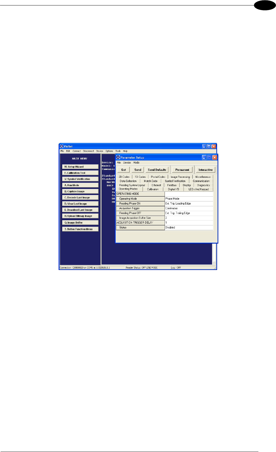
Advanced Configuration Using VisiSet™
Advanced configuration can be performed through the VisiSet™ program by selecting
Device> Get Configuration From Temporary Memory to open the Parameter Setup window in
off-line mode. Advanced configuration is addressed to expert users being able to complete a
detailed reader configuration. The desired parameters can be defined in the various folders
of the Parameter Setup window and then sent to the reader memory (either Temporary or
Permanent):
Figure 18 - VisiSet™ Parameter Setup Window
Host Mode Programming
The reader can also be configured from a host computer using the Host Mode programming
procedure, by commands via the serial interface. See the Host Mode Programming file on
the CD-ROM.
Alternative Layouts
If you need to install an Ethernet network, ID-NET™ network, Fieldbus network, Pass-
Through network, Multiplexer network or an RS232 Master/Slave refer to the Matrix 400™
Reference Manual.
Code Quality Verification
Matrix 400™ can be used as a Code Quality Verifier according to the ISO/IEC 15415,
ISO/IEC 15416, AS9132, and AIM DPM Standards. For more details see the Matrix 400™
Code Quality Verifier Solution manual on the CD-ROM.

MATRIX 400™ REFERENCE MANUAL
20
2
2 INTRODUCTION
2.1 PRODUCT DESCRIPTION
Matrix 400™ is a Datalogic industrial compact 2D imager designed and produced to be a
high performance affordable solution for both linear and two-dimensional code reading
applications.
Matrix 400™ uses imaging technology and provides complete reading system functions by
integrating image capturing, decoding and communicating in a single compact and versatile
product.
Matrix 400™ sets a new standard in 2D imager technology offering high performance with
improved reading flexibility thanks to its intrinsic modularity.
Matrix 400™ features excellent reading and verifying performance thanks to 1.3 and 2.0
Mega pixel sensors and smart proprietary decoding libraries.
The modular combination of Mega pixels sensors, powerful lighting and adjustable C-Mount
lenses provide high flexibility in covering application with various requirements.
Innovative X-PRESS™ interface, combined with Blue Diamonds™ aiming and focusing
system and a Good Read Spot, enhance the ease of setup and use.
Rugged construction, IP67 protection and max 50°C operative temperature make the Matrix
400™ the ideal product for industrial applications.
Matrix 400™ has been developed for use in numerous industries like:
Automotive
DPM (Direct Part Marked) Reading and Verification
Tires Sorting
Electronics
Large PCB Board Tracking
Electronics Product Tracking
Distribution & Retail Industry
Presentation Scanner
Small Objects Tracking & Sorting
Warehouse applications
Medical & Pharmaceutical
Medical Devices Traceability
Pharmaceutical and Medicine Manufacturing
Chemical & Biomedical Analysis
Food & Beverage
Work in Progress Traceability
Code Quality Control
This technology intrinsically provides omni-directional reading.

INTRODUCTION
21
2
Standard Application Program
A Standard Application Program is factory-loaded onto Matrix 400™. This program controls
code reading, data formatting, serial port and Ethernet interfacing, and many other operating
and control parameters. It is completely user configurable from a Laptop or PC using the
dedicated configuration software program VisiSet™, provided on CD-ROM with the reader.
There are different programmable operating modes to suit various code reading system
requirements.
Quick, automatic focus, positioning, calibration and code setting of the imager can be
accomplished using the X-PRESS™ button and LEDs on top of the reader without the
necessity of a PC.
The previous functions can also be performed through VisiSet™ through the Setup Wizard.
This tool includes visual feedback from the reader.
VisiSet™ provides a Calibration Tool to verify the exact positioning of the reader and to
maximize its reading performance.
Statistics on the reading performance can also be visualized through a dedicated window in
VisiSet™.
Symbol Verification can be performed through VisiSet™ when the reader has been installed
and setup as a Verifier station. For details see the Matrix Code Quality Verifier Solution
manual.
Programmability
If your requirements are not met by the Standard Application Program, Custom Application
Programs can be requested at your local Datalogic distributor.
Some of the main features of this reader are given below:
Excellent Performance
1.3 MPixels (SXGA) & 2.0 MPixels (UXGA) models
Adjustable focus through C-Mount lenses
Powerful Internal Lighting Systems
Outstanding decoding capability on 1D, 2D, Stacked, Postal symbologies
Excellent performance on DPM applications
Omni-directional reading
Frame Rate up to 27 frames/sec for SXGA models and 15 frame/sec for UXGA models
Region Of Interest Windowing for higher frame rate
Up to 100 readable codes in a single frame

MATRIX 400™ REFERENCE MANUAL
22
2
Ease of Setup
Quick installation without PC by using X-PRESS™ interface for easy and intuitive setup
Blue Diamonds™ aiming and focusing system
Automatic Imager calibration and Code Settings
Calibration Tool to verify exact code positioning in the Field of View and to maximize the
reading performance
Windows-based VisiSet™ software to configure the reader parameters via PC serial or
Ethernet interface
User-defined database of Image Acquisition Settings (parameter sets)
Smart Fast Bracket
Ease of Use
X-PRESS™ interface LEDs provide operational and performance feedback
Green Spot and beeper for immediate Good Read feedback
Different operating modes to suit various application requirements
Multi Image Acquisition Settings for higher reader flexibility
Run Time Self-Tuning for extreme reader flexibility
Image saving and storage with buffering capability
Diagnostic software tools
Flexible Solution
Modular design
Adjustable C-Mount lenses
Complete set of Accessories like external lighting systems, light filters, mounting brackets,
connection boxes, cables and photocells
Ethernet Connectivity with TCP/IP socket for reader parameter configuration, data and
image transfer, HTTP server, FTP and mail client, etc.
3 serial communication interfaces (Main, Auxiliary, ID-NET™)
General purpose optocoupled I/Os
Versatility
Excellent reading performance on Direct Part Marked (DPM) symbols
Code Quality Verification according to ISO/IEC 16022, ISO/IEC 18004, ISO/IEC 15415,
ISO/IEC 15416 and AS9132 and AIM DPM standards.
Match Code option with a user-defined match code database

INTRODUCTION
23
2
Industrial Strength
Industrial compact 2D reader
Rugged full metal construction
Sealed circular connectors
IP67 protection class
50 °C max operating temperature
Supply voltage ranges from 10 to 30 Vdc
The reader is particularly suitable for industrial environments where protection against harsh
external conditions is required.
The reader is contained in an aluminum housing; with its internal illuminator, C-Mount lens
and protective cover, the mechanical dimensions are 123 x 60.5 x 87 mm and it weighs
about 482 g.
Electrical connection of Power, Host interfaces and I/O signals is provided through an M16
(IP67) 19-pin connector (Figure A, 9). A standard M12 D-Coded (IP67) Ethernet connector is
present on Matrix 400 XXX-X1X models (Figure A, 10).
MATRIX 400™ REFERENCE MANUAL
24
2
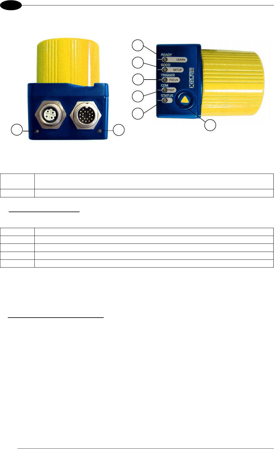
2.2 INDICATORS AND KEYPAD BUTTON
Figure 19 - Indicators
The following LED indicators are located on the reader:
NET yellow LED indicates connection to the on-board Ethernet network (for Ethernet
models) (Figure 19, 1)
PWR blue LED indicates that the reader is connected to the power supply (Figure 19, 2)
In normal operating mode the colors and meaning of the five LEDs are illustrated in the
following table:
READY green LED indicates that the reader is ready to operate (Figure 19, 3)
GOOD green LED confirms successful reading (Figure 19, 4)
TRIGGER yellow LED indicates the status of the reading phase (Figure 19, 5)
COM yellow LED indicates active communication on the main serial port * (Figure 19, 6)
STATUS red LED indicates a NO READ result (Figure 19, 7)
* When connected to a Fieldbus network through the CBX500, the COM LED is always active, even in the
absence of data transmission, because of polling activity on the Fieldbus network.
During the reader startup (reset or restart phase), these five LEDs blink for one second.
In X-PRESS™ Configuration mode the colors and meaning of these five LEDs are described
in par. 2.4.
The keypad button (Figure 19, 8), is software programmable. By default it starts the X-
PRESS™ interface for quick installation without using a PC (see chp. 1).
1 2
3
4
5
6
7
8
INTRODUCTION
25
2
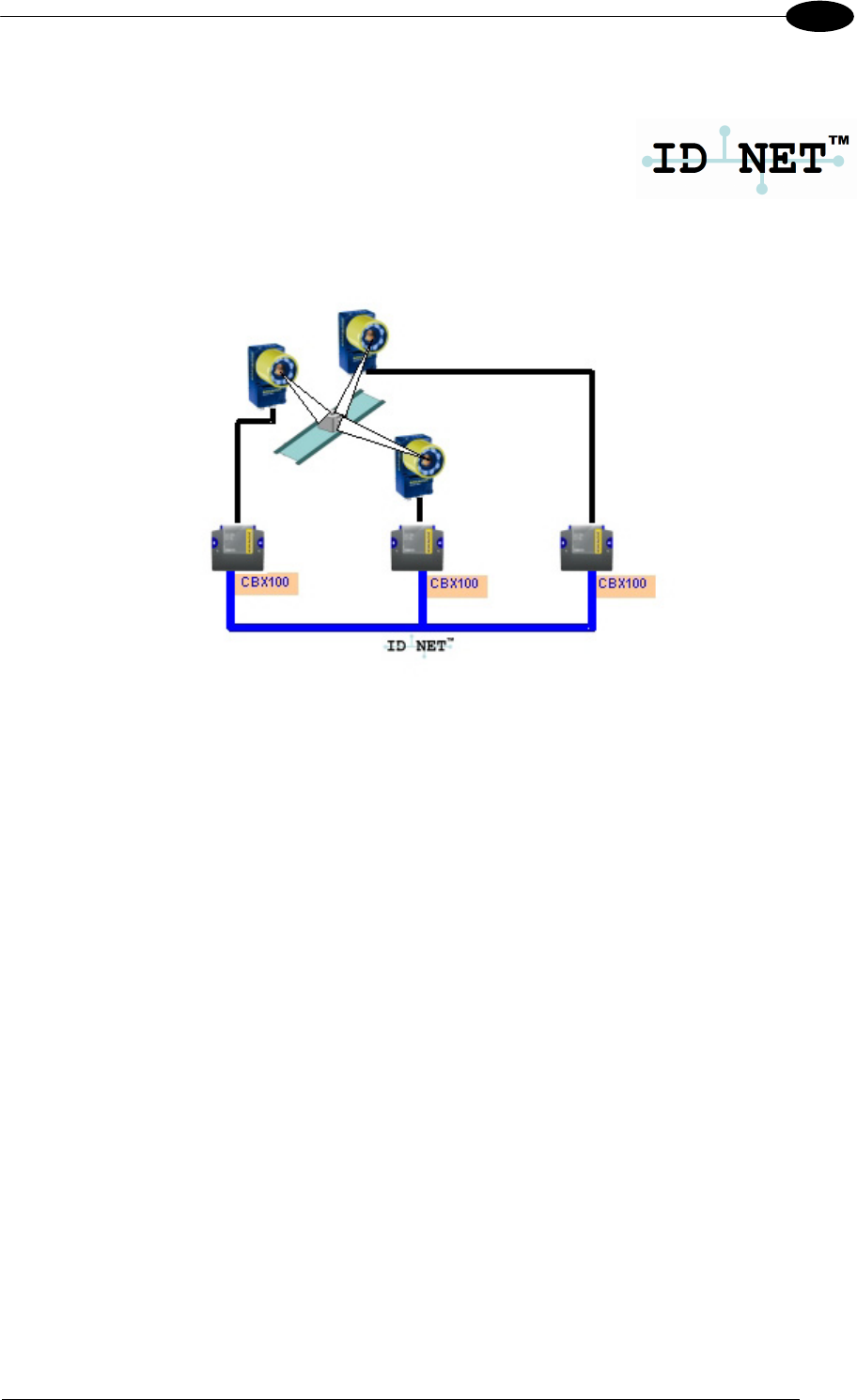
2.3 ID-NET™
The ID-NET™ network is a built-in high-speed interface dedicated
for high-speed reader interconnection. ID-NET™ is in addition to
the Main and Auxiliary serial interfaces.
The following network configurations are available:
ID-NET™ M/S Synchronized: Single station – multiple readers
ID-NET™ interface allows local connection of multiple readers reading different sides of the
same target. All readers share a single presence sensor and activate/deactivate
simultaneously.
At the end of each reading phase a single data message is transmitted to the host.
Thanks to ID-NET™, data communication among readers is highly efficient so that an
immediate result will be available.
MATRIX 400™ REFERENCE MANUAL
26
2
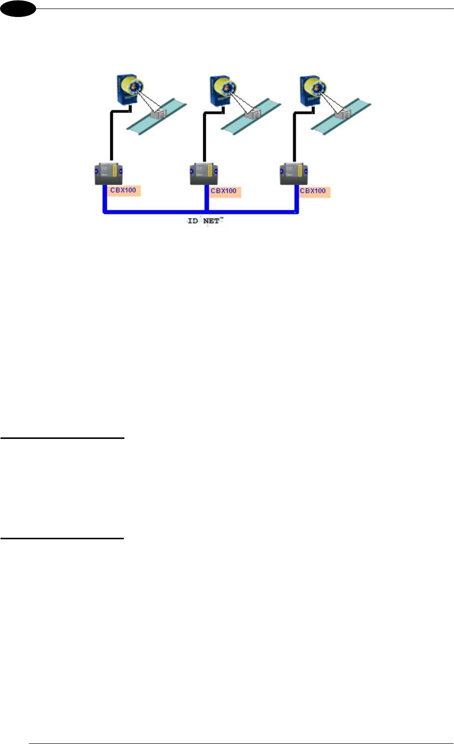
ID-NET™ M/S Multidata: Multiple stations – single reader
ID-NET™ interface allows connection of readers reading objects placed on independent
conveyors. All readers are typically located far away from each other and they use a
dedicated presence sensor.
At the end of each reading phase, each reader transmits its own data message to the host.
Thanks to ID-NET™, data collection among readers is accomplished at a high speed without
the need of an external multiplexing device. This leads to an overall cost reduction and to a
simple system wiring.
2.3.1 How To Setup/Configure the Reader Network
A complete ID-NET™ reader network can be easily setup through VisiSet™ as follows:
Mounting & Connection
1. Mechanically mount/install all the readers (refer to par. 3.2 and 3.3).
2. Wire ID-NET™ (refer to par. 4.3 or 5.5).
3. Power up the entire system.
Configuration of Slaves
1. Connect a PC equipped with VisiSet™ to the Main, Auxiliary or Ethernet interface of the
planned Slave reader.
2. Launch VisiSet™ and connect to the Slave reader.
3. From the VisiSet™ Device Menu select "Parameter Setup".
4. Set the Role of the Slave reader (Synchronized or Multidata) from the
Reading System Layout > Device Network Setting > Topology Role parameter.
5. Set the Slave Address according to the desired value 0-31 from the
Reading System Layout > Device Network Setting > Slave Address parameter. Each
reader must have a different Address on the ID-NET™ Network.
6. If necessary, set the ID-NET™ baudrate from the Reading System Layout >
Device Network Setting > Network Baud Rate parameter, (500 kbs default).
INTRODUCTION
27
2
7. Configure the other device parameters via VisiSet™ [Operating Mode, Calibration, Data
Collection parameters, etc.].
8. If using the CBX connection box equipped with a BM100 Backup module, perform Device
Backup at the Slave.
The Slave device is now Configured. Repeat these steps for each Slave reader in the ID-
NET™ network.
Configuration of Master
1. Connect a PC equipped with VisiSet™ to the Main, Auxiliary or Ethernet interface of the
planned Master reader.
2. Launch VisiSet™ and connect to the Master reader.
3. From the VisiSet™ Device Menu select "Parameter Setup".
4. Set the Role of the Master reader (Synchronized or Multidata) from the
Reading System Layout > Device Network Setting > Topology Role parameter.
5. Enable the planned Slave device N from the Reading System Layout >
Expected Slave Device #N > Status parameter and, if desired, set the related
identification string from the Expected Slave Device #N > Device Description parameter.
Repeat this step for all planned Slave devices.
6. If necessary, set the ID-NET™ baudrate from the Reading System Layout >
Device Network Setting > Network Baud Rate parameter, (500 kbs default).
7. Configure the other device parameters via VisiSet™ [Operating Mode, Calibration, Data
Collection parameters, etc.].
8. If using the CBX connection box equipped with a BM100 Backup module, perform Device
Backup at the Master.
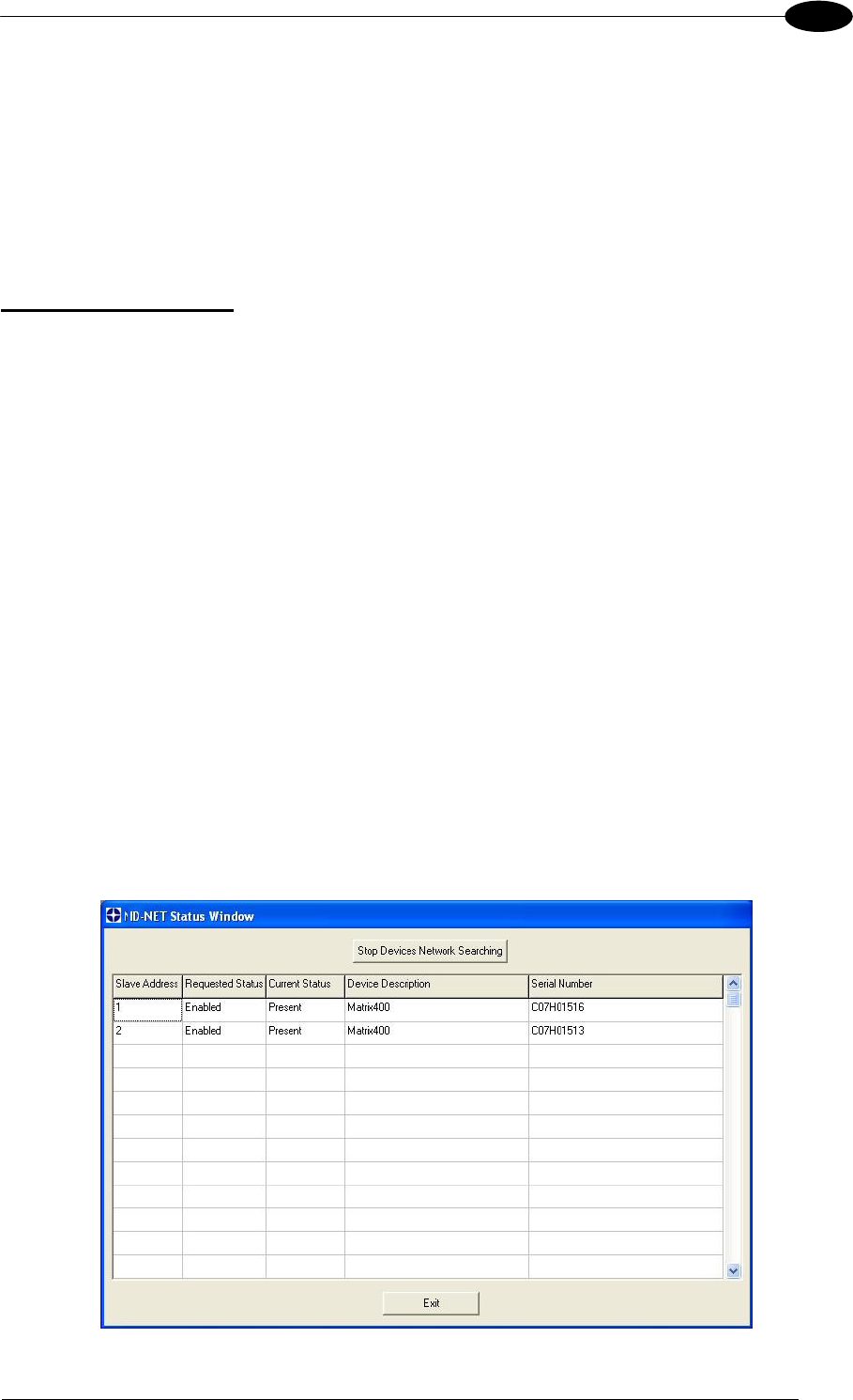
9. From the VisiSet™ Device Menu select "ID-NET™ Status Window" and click on the
"Look For Devices On Network" button to check the status of the expected Slave devices
within the ID-NET™ network.
The reader network is ready.
MATRIX 400™ REFERENCE MANUAL
28
2
2.4 X-PRESS™ HUMAN MACHINE INTERFACE
X-PRESS™ is the intuitive Human Machine Interface designed to improve ease of
installation and maintenance.
Status information is clearly presented by means of the five colored LEDs,
whereas the single push button gives immediate access to the following
relevant functions:
Learn to self-detect and auto-configure for reading unknown codes
Setup to perform Exposure Time and Gain calibration.
Focus/Locate to turn on the Blue Diamonds™ to aid focusing and
positioning.
Test with bar graph visualization to check static reading performance
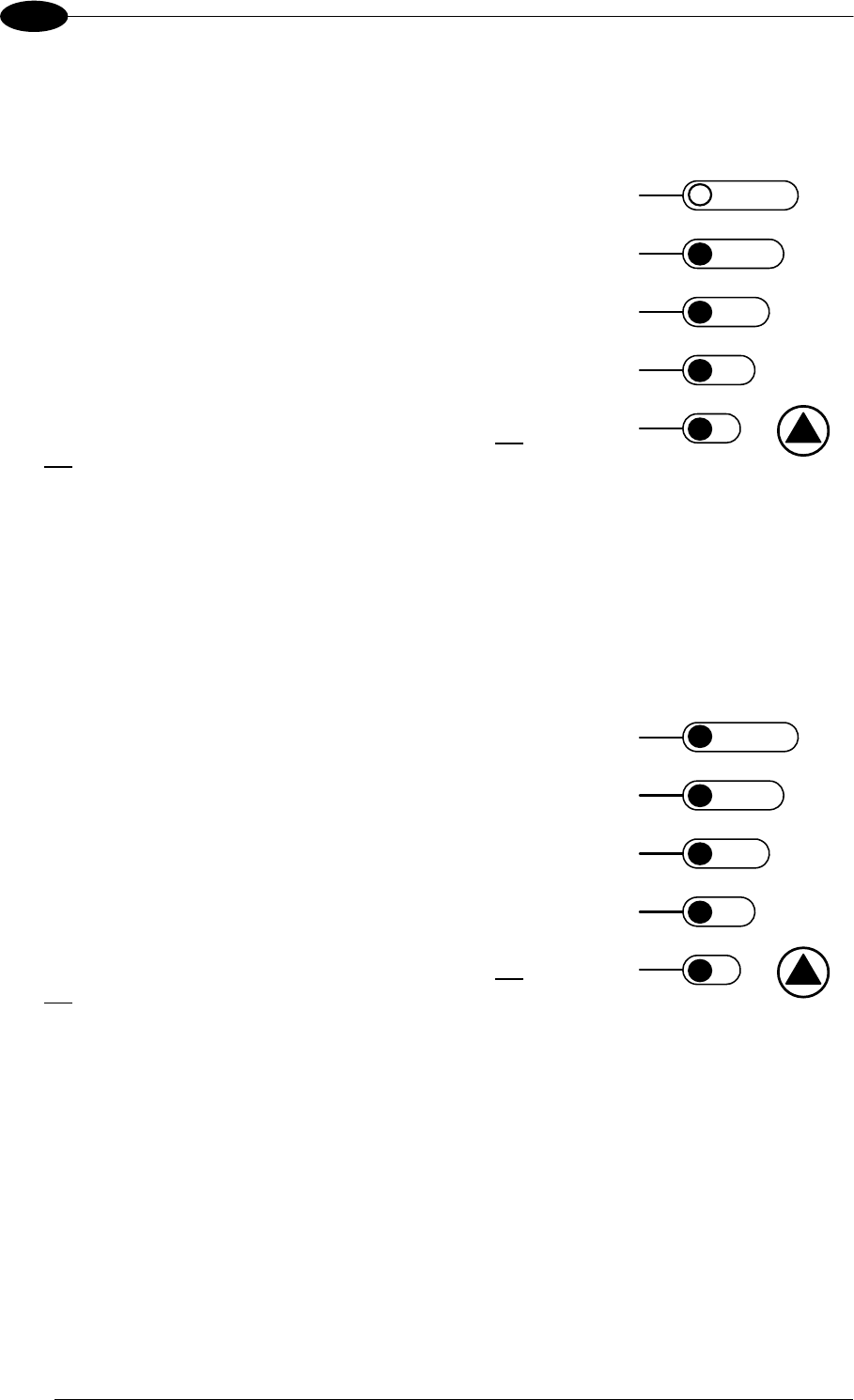
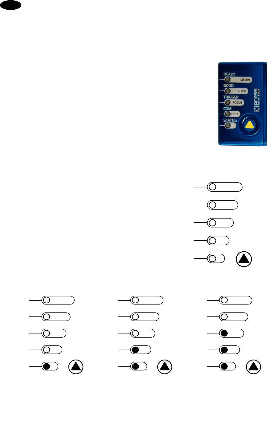
2.4.1 X-PRESS™ Functions
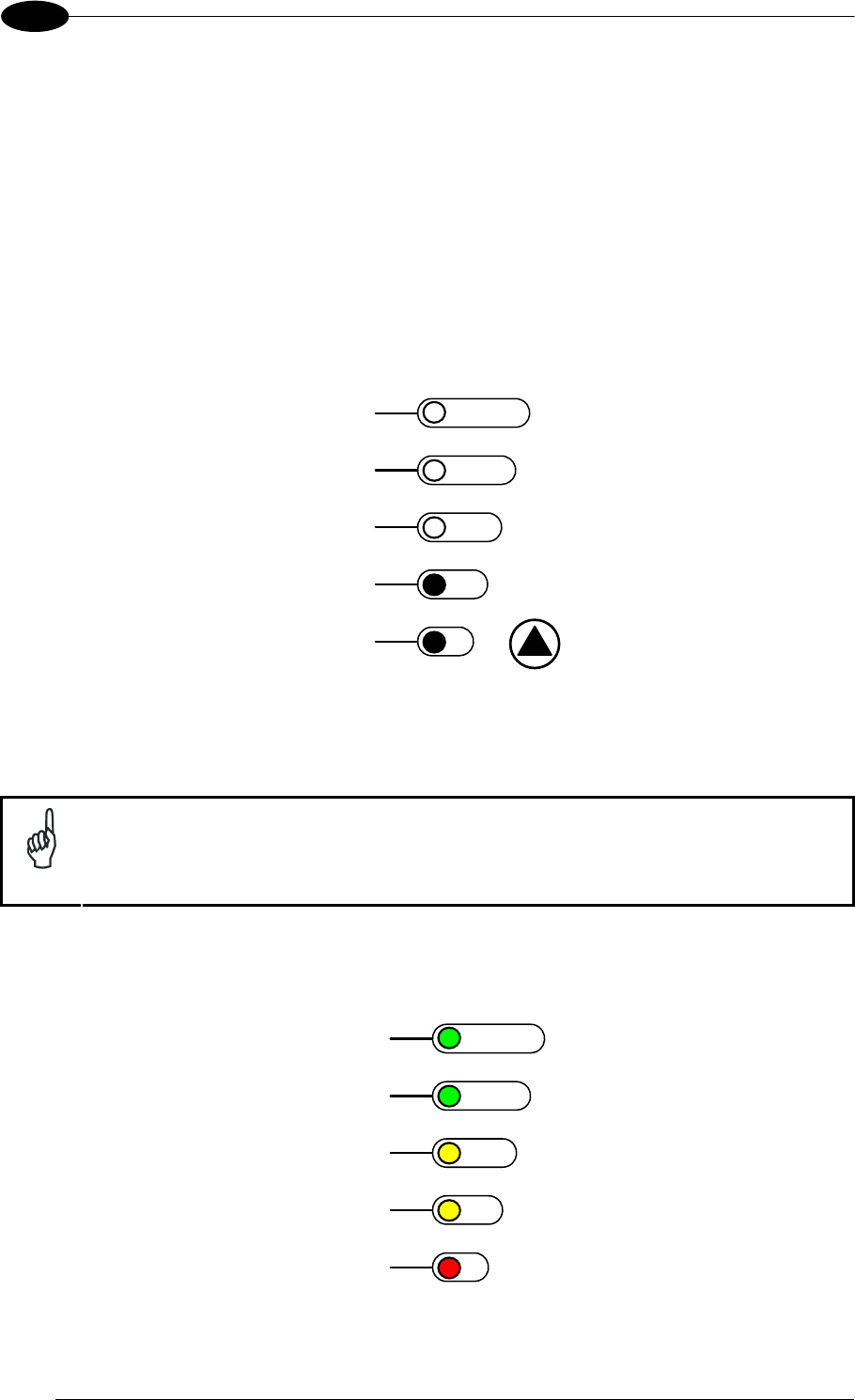
Quick access to the following functions is provided by
an easy procedure using the push button:
1 – Press the button (the Status LED will give a
visual feedback).
2 – Hold the button until the specific function LED is
on (Test, Focus, Setup or Learn).
3 – Release the button to enter the specific function.
READY
green
green
y
ellow
y
ellow
red
SETUP
FOCUS
T
ES
T
LEARN
GOOD
T
RIGGER
COM
STATUS
Once button is pressed, the cycle of LEDs activation is as follows:
READY
green
green
y
ellow
y
ellow
red
SETUP
FOCUS
T
ES
T
LEARN
GOOD
T
RIGGER
COM
STATUS
READY
green
green
y
ellow
y
ellow
red
SETUP
FOCUS
T
ES
T
LEARN
GOOD
T
RIGGER
COM
STATUS
READY
green
green
y
ellow
y
ellow
red
SETUP
FOCUS
T
ES
T
LEARN
GOOD
T
RIGGER
COM
STATUS
Release button
to Exit
Release button
to enter Test Mode
Release button
to enter Focus/Locate Mode
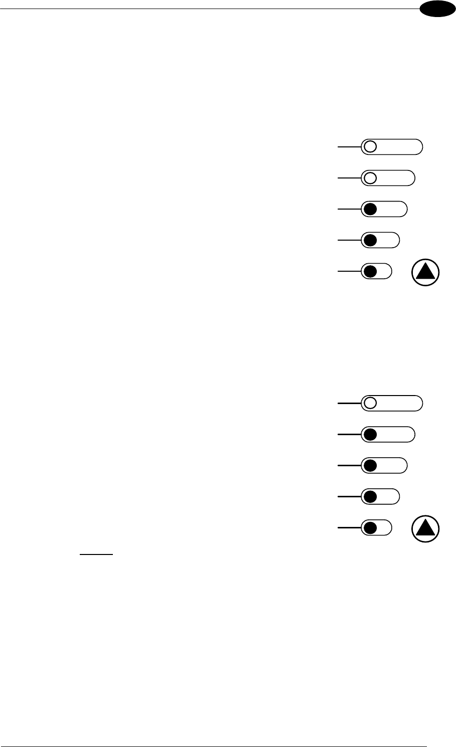
INTRODUCTION
29
2
READY
green
green
y
ellow
y
ellow
red
SETUP
FOCUS
T
ES
T
LEARN
GOOD
T
RIGGER
COM
STATUS
READY
green
green
y
ellow
y
ellow
red
SETUP
FOCUS
T
ES
T
LEARN
GOOD
T
RIGGER
COM
STATUS
READY
green
green
y
ellow
y
ellow
red
SETUP
FOCUS
T
ES
T
LEARN
GOOD
T
RIGGER
COM
STATUS
Release button
to enter Setup Mode
Release button
to enter Learn Mode
(cycle)
Release button
to Exit
Test Mode (Function 1)
Once entered, the Bar Graph on the five LEDs is activated and if the imager starts reading
codes the Bar-Graph shows the Good Read Rate. In case of a NO READ condition, only the
Status LED is on and blinks.
The Bar Graph has the following meaning:
READY
95%
75%
60%
40%
20%
SETUP
FOCUS
T
ES
T
LEARN
GOOD
T
RIGGER
COM
STATUS
To exit the Test Mode, press the X-PRESS™ push button once.
NOTE
By default, the Test exits automatically after three minutes.
Focus/Locate (Function 2)
This function causes the Blue Diamonds™ to turn on. The Blue Diamonds™ can be used to
focus the lens at the desired reading distance and since they are centered on the FOV they
can also be used to position the imager on the code. The Focus LED blinks to indicate this
state.
To exit the Focus/Locate Mode, press the X-PRESS™ push button once. The Blue
Diamonds™ turn off.

MATRIX 400™ REFERENCE MANUAL
30
2
Setup (Function 3)
Once entered, the imager automatically performs Image Acquisition parameter calibration for
the specific code presented to it.
The Setup LED will blink until the procedure is completed.
The Setup procedure ends when the Image Acquisition parameters are successfully saved in
the reader memory, the Setup LED will remain on continuously and Matrix 400™ emits 3 high
pitched beeps.
If the calibration cannot be reached after a timeout of about 5 (five) seconds Matrix 400™ will
exit without saving the parameters to memory, the Setup LED will not remain on continuously
but it will just stop blinking. In this case Matrix 400™ emits a long low pitched beep.
Learn (Function 4)
Once entered, the imager starts a procedure to automatically detect and recognize codes
which are presented to it.
The Learn LED will blink until the procedure is completed.
The Learn procedure ends when the Image Processing and Decoding parameters are
successfully saved in the reader memory, the Learn LED will remain on continuously and
Matrix 400™ emits 3 high pitched beeps.
If the calibration cannot be reached after a timeout of about 3 (three) minutes, Matrix 400™ will
exit without saving the parameters to memory, the Learn LED will not remain on continuously
but it will just stop blinking. In this case Matrix 400™ emits a long low pitched beep.
2.5 MODEL DESCRIPTION
The Matrix 400™ reader is available in different versions according to the following
characteristics:
MATRIX 400 XXX-0X0
Illuminators
0 = BS (Base, No Illuminator)
Lens
0 = C-Mount (No Lens)
Sensor Size
4
= SXGA (1280x1024)
6 = UXGA (1600x1200)
Interface
0 = Serial
1 = Ethernet

INTRODUCTION
31
2
2.6 ACCESSORIES
The following accessories can be used with the Matrix 400™ reader.
Accessory Description Order No.
Lenses
LNS-1006 6 mm C-Mount Lens 93ACC1793
LNS-1109 9 mm C-Mount Lens 93ACC1794
LNS-1112 12.5 mm C-Mount Lens 93ACC1795
LNS-1116 16 mm C-Mount Lens 93ACC1796
LNS-1125 25 mm C-Mount Lens 93ACC1797
LNS-1135 35 mm C-Mount Lens 93ACC1798
LNS-1150 50 mm C-Mount Lens 93ACC1799
Internal Illuminators
LT-001 Internal Illuminator Red Narrow Angle 93A401019
LT-002 Internal Illuminator Red Wide Angle 93A401020
LT-003 Internal Illuminator White Narrow Angle 93A401021
LT-004 Internal Illuminator White Wide Angle 93A401022
LT-006 Internal Illuminator Red Super Narrow Angle 93A401024
External Illuminators
LT-100 Cone Lighting System 93A401003
LT-200 Spot Lighting System 93A401004
LT-210 Mini-Spot Lighting System 93A401012
LT-300 Ring Lighting System 93A401008
LT-314 45° Dark Field Ring Lighting System 93A401013
LT-316 60° Dark Field Ring Lighting System 93A401014
LT-410 Coaxial Lighting System 93A401015
LT-510 Mini-Dome Lighting System 93A401016
LT-511 Dome Lighting System 93A401017
LT-630 Four Bar Lighting System 93A401018
Filters
FLT-111 IR Cut Filter (d 27 mm) 93ACC1800
FLT-112 IR Cut Filter (d 25.5 mm) 93ACC1801
FLT-121 Linear Polarizer (d 27 mm) 93ACC1802
FLT-122 Linear Polarizer (d 25.5 mm) 93ACC1803
Cables
CAB-MS01 M16-IP67 Cable To CBX (1M) 93A051358
CAB-MS03 M16-IP67 Cable To CBX (3M) 93A051359
CAB-MS05 M16-IP67 Cable To CBX (5M) 93A051360
CAB-ETH-M01 M12-IP67 Ethernet Cable (1M) 93A051346
CAB-ETH-M03 M12-IP67 Ethernet Cable (3M) 93A051347
CAB-ETH-M05 M12-IP67 Ethernet Cable (5M) 93A051348
Connection Boxes
CBX100 Compact Connection Box 93A301067
CBX500 Modular Connection Box 93A301068
BM100 Backup Module for CBX100/500 93ACC1808
* BM150 Display Module for CBX500 93ACC1809
* BM300/BM310 Profibus Module STD/IP65 for CBX500 93ACC1810, 93ACC1811
* BM400 DeviceNet Module IP65 for CBX500 93ACC1814
Power Supplies
PG6002 AC/DC Power Supply Unit (US) 93ACC1718
PG6001 AC/DC Power Supply Unit (UK) 93ACC1719
PG6000 AC/DC Power Supply Unit (EU) 93ACC1720
LTC-630 Four Bar Lighting System Controller 93ACC1790
Sensors
PH-1 Photocell Kit PNP 93ACC1791
MEP- 543 Photocell Kit-NPN 93ACC1728
Brackets
USX-60 Adjustable Bracket 93ACC1729
BK-4410 Coaxial LT Bracket Matrix 400 93ACC1804
BK-4990 Generic LT Bracket Matrix 400 93ACC1805
ISO/IEC Calibration Chart Calibration Chart for Code Verifier Solution 93ACC1841
* Accessories compatible with Matrix 400™ application software 5.20 and later.
MATRIX 400™ REFERENCE MANUAL
32
2
The following table shows the correct lens/illuminator combinations to be used for Matrix
400™ imager assembly.
Lenses Internal Illuminators
93ACC1793 LNS-1006 6 mm C-Mount Lens
(only for Matrix 400 600-0x0 models)
93A401020
93A401022
LT-002
LT-004
Red Wide Angle
White Wide Angle
93ACC1794 LNS-1109 9 mm C-Mount Lens 93A401020
93A401022
LT-002
LT-004
Red Wide Angle
White Wide Angle
93ACC1795 LNS-1112 12.5 mm C-Mount Lens 93A401020
93A401022
LT-002
LT-004
Red Wide Angle
White Wide Angle
93ACC1796 LNS-1116 16 mm C-Mount Lens 93A401019
93A401021
LT-001
LT-003
Red Narrow Angle
White Narrow Angle
93ACC1797 LNS-1125 25 mm C-Mount Lens 93A401019
93A401021
LT-001
LT-003
Red Narrow Angle
White Narrow Angle
93ACC1798 LNS-1135 35 mm C-Mount Lens 93A401024 LT-006 Red Super Narrow Angle
93ACC1799 LNS-1150 50 mm C-Mount Lens 93A401024 LT-006 Red Super Narrow Angle
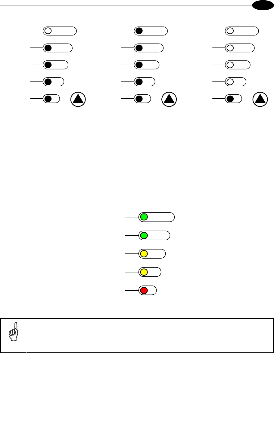
2.7 APPLICATION EXAMPLES
Matrix 400™ is profitably used in the omnidirectional reading of 2D, stacked, linear and
postal codes for example in automated document handling and mail processing systems
(see Figure 20).
Figure 20 - Address Coded in Datamatrix Symbology for Automated Mail Processing
The Matrix 400™ high resolution image sensors allow the reading of many small codes in a
single image (see 96 vial application in Figure 21).
Figure 21 - 96-Vial Rack
INTRODUCTION
33
2
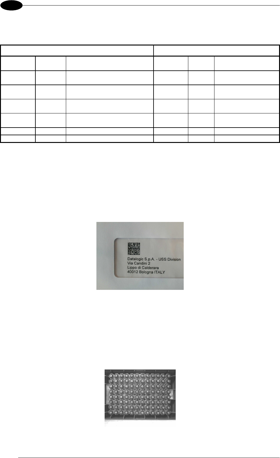
Matrix 400™ assures the reading of deformed and / or overprinted codes, even though
damaged or printed on high reflective surfaces (see Figures 22, 23, 24).
Figure 22 - Unidose Flow-Pack with PDF417 Code
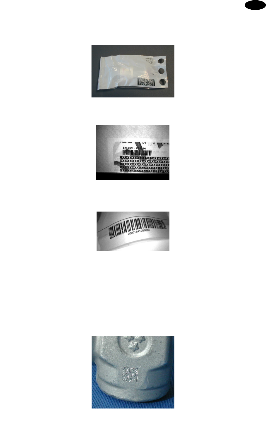
Figure 23 - Overprinted Barcode Readable by Matrix 400™ also Through the Envelope Window Film
Figure 24 - Barcode Printed on Curved Surface Readable by Matrix 400™ in spite of Image Optical
Distortion
Matrix 400™ is also very powerful in reading low-contrast direct part marked codes (see
Figures 25, 26, 27, 28 and 29).
Figure 25 - Dot Matrix Code Directly Marked on Metal Surface by Using Dot Peening Technology
MATRIX 400™ REFERENCE MANUAL
34
2
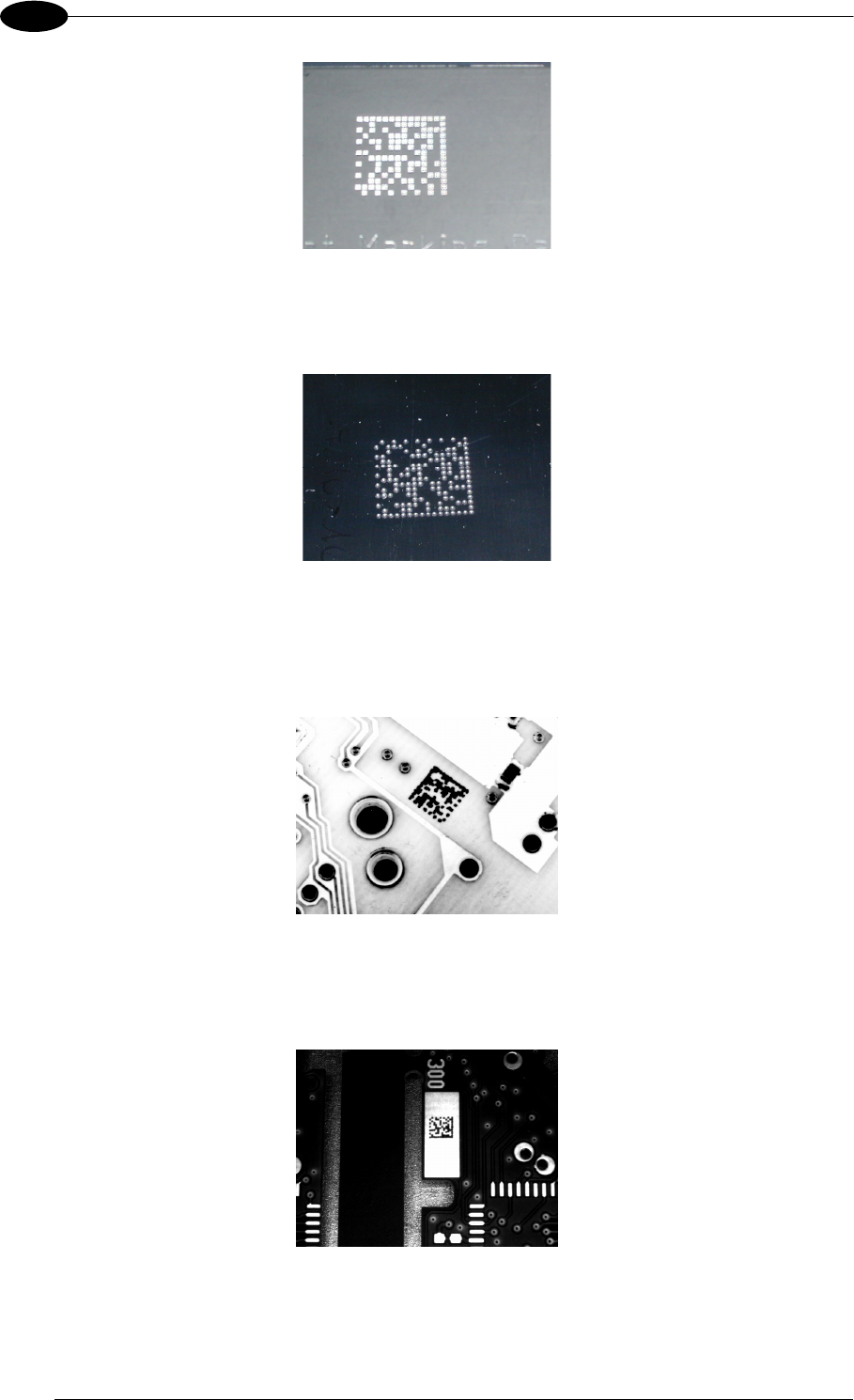
Figure 26 - Dot Peening Marking on Metal Surface with Multi-dot per Code Element
Figure 27 - Directly Marked Dot Matrix Code Characterized by Outstanding Separation Distance between
Adjacent Code Elements
Figure 28 - DataMatrix Code Directly Marked on PCB Surface by Using Laser Etching Technology
Figure 29 - Dot Matrix Code Directly Marked on PCB Copper Pad by Using Ink-Jet Technology
INTRODUCTION
35
2
2.8 EXTERNAL LIGHTING SYSTEMS
In some direct part marking applications best reading results are obtained by using an
external lighting system. A series of accessory illuminators are available which cover a
variety of applications.
The LT-100 Cone Lighting System provides a circular symmetrical light source designed for
the following applications:
with uneven or noisy background surfaces
where dot peening or laser etching codes are directly marked onto metal surfaces or
PCBs and need to be highlighted
in the presence of highly reflective surfaces (metal, glass, etc.) causing direct reflections
Figure 30 - LT-100 Cone Lighting System
The LT-200 Spot Lighting System provides a high intensity light source designed for the
following applications:
with uneven, noisy and scratched surfaces
where dot peening or laser etching codes are directly marked onto metal surfaces or
PCBs and need to be highlighted. Here the use of more than one Spot Light can remove
any shadowing effect.
in the presence of highly reflective surfaces (metal, glass, etc.) causing direct reflections.
Low light path to surface angles strongly reduce direct reflections.
Figure 31 - LT-200 Spot Lighting System
MATRIX 400™ REFERENCE MANUAL
36
2
The LT-210 Mini Spot Lighting System provides a high intensity light source designed for the
following applications:
with uneven, noisy and scratched surfaces
where dot peening or laser etching codes are directly marked onto metal surfaces or
PCBs and need to be highlighted. Here the use of more than one Spot Light can remove
any shadowing effect.
in the presence of highly reflective surfaces (metal, glass, etc.) causing direct reflections.
Low light path to surface angles strongly reduce direct reflections.
Figure 32 - LT-210 Mini Spot Lighting System
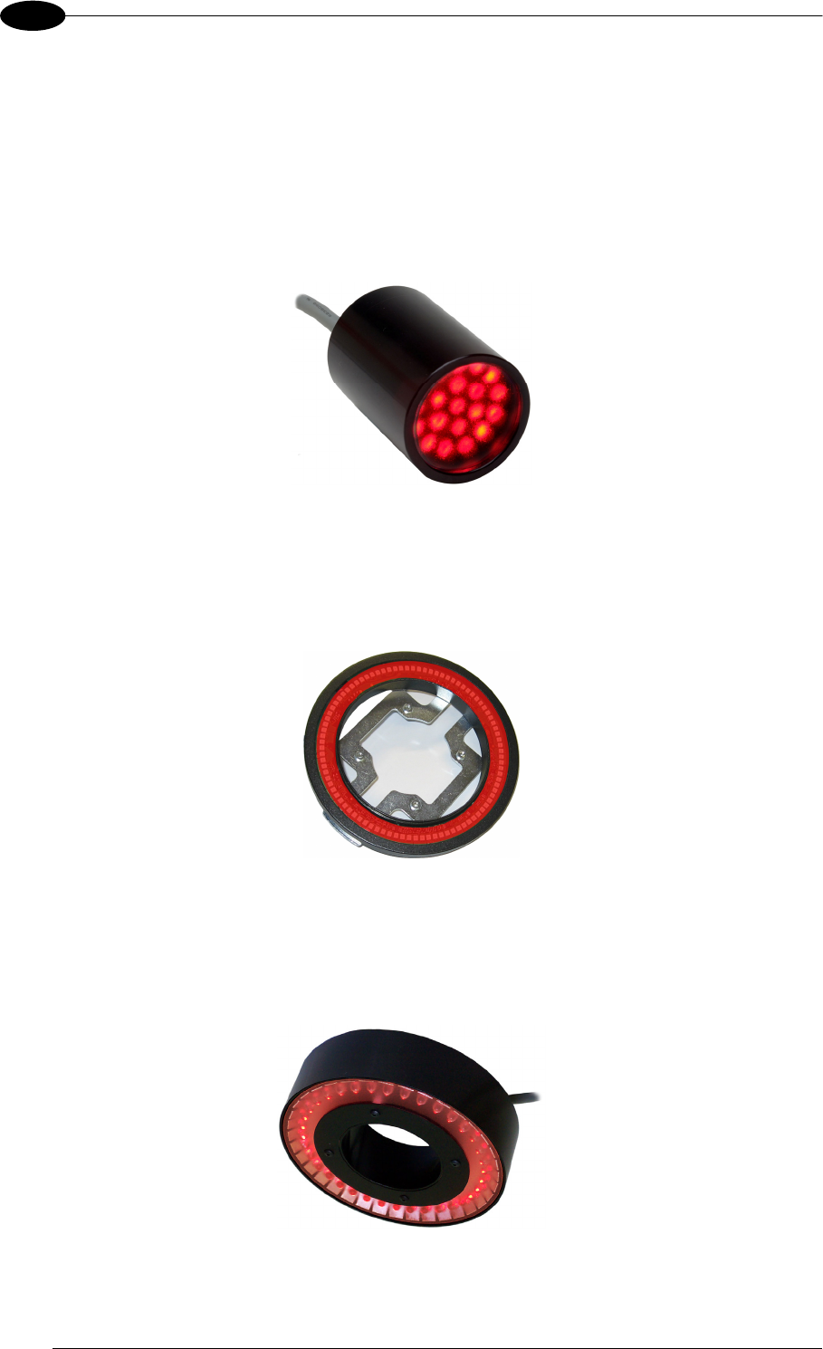
The LT-300 Ring Lighting System is designed for reading codes produced by Dot Peening or
Laser Etching on flat, reflective parts.
Figure 33 - LT-300 Ring Lighting System
The LT-314 45° Dark Field Ring Lighting System is designed for reading codes produced by
Dot Peening or Laser Etching on flat, reflective parts.
Figure 34 - LT-314 45° Dark Field Ring Lighting System
INTRODUCTION
37
2
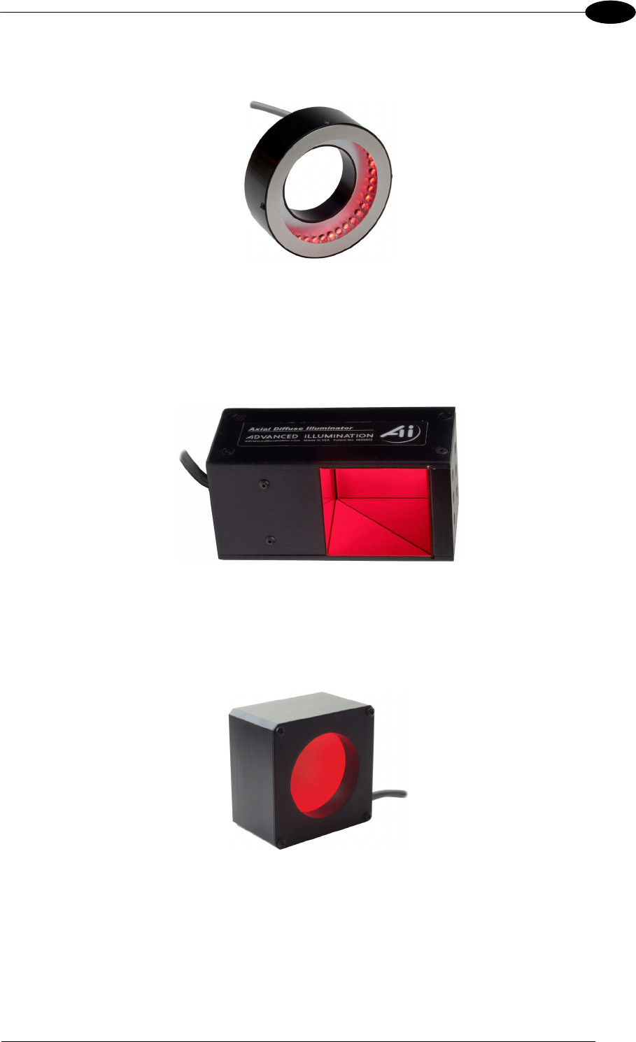
The LT-316 60° Dark Field Ring Lighting System is designed for reading codes produced by
Dot Peening (especially by a 120° stylus) or Laser Etching on flat, reflective parts.
Figure 35 - LT-316 60° Dark Field Ring Lighting System
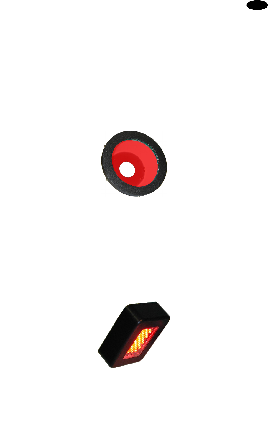
The LT-410 Coaxial Lighting System is an axial diffuse illuminator designed for reading
codes produced by Dot Peening or Laser Etching on flat parts having a matte, specular or
mixed surface reflectivity.
Figure 36 - LT-410 Coaxial Lighting System
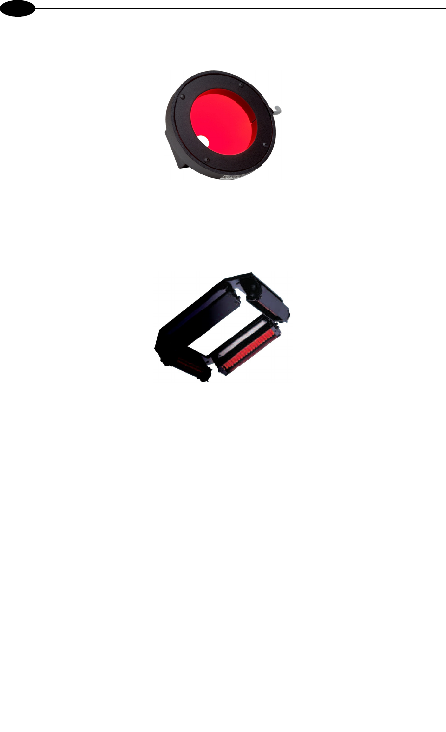
The LT-510 Mini Dome Lighting System is a diffuse mini dome light designed for reading
printed label or Direct Marking codes on small parts with a curved or specular surface.
Figure 37 - LT-510 Mini Dome Lighting System
MATRIX 400™ REFERENCE MANUAL
38
2
The LT-511 Dome Lighting System is a diffuse dome light designed for reading printed label
or Direct Marking codes on parts with a curved surface.
Figure 38 - LT-511 Dome Lighting System
The LT-630 Four Bar Lighting System is designed for Code verification applications
according to ISO/IEC 15415 or ISO/IEC 15416 specifications.
Figure 39 - LT-630 Four Bar Lighting System
INSTALLATION
39
3
3 INSTALLATION
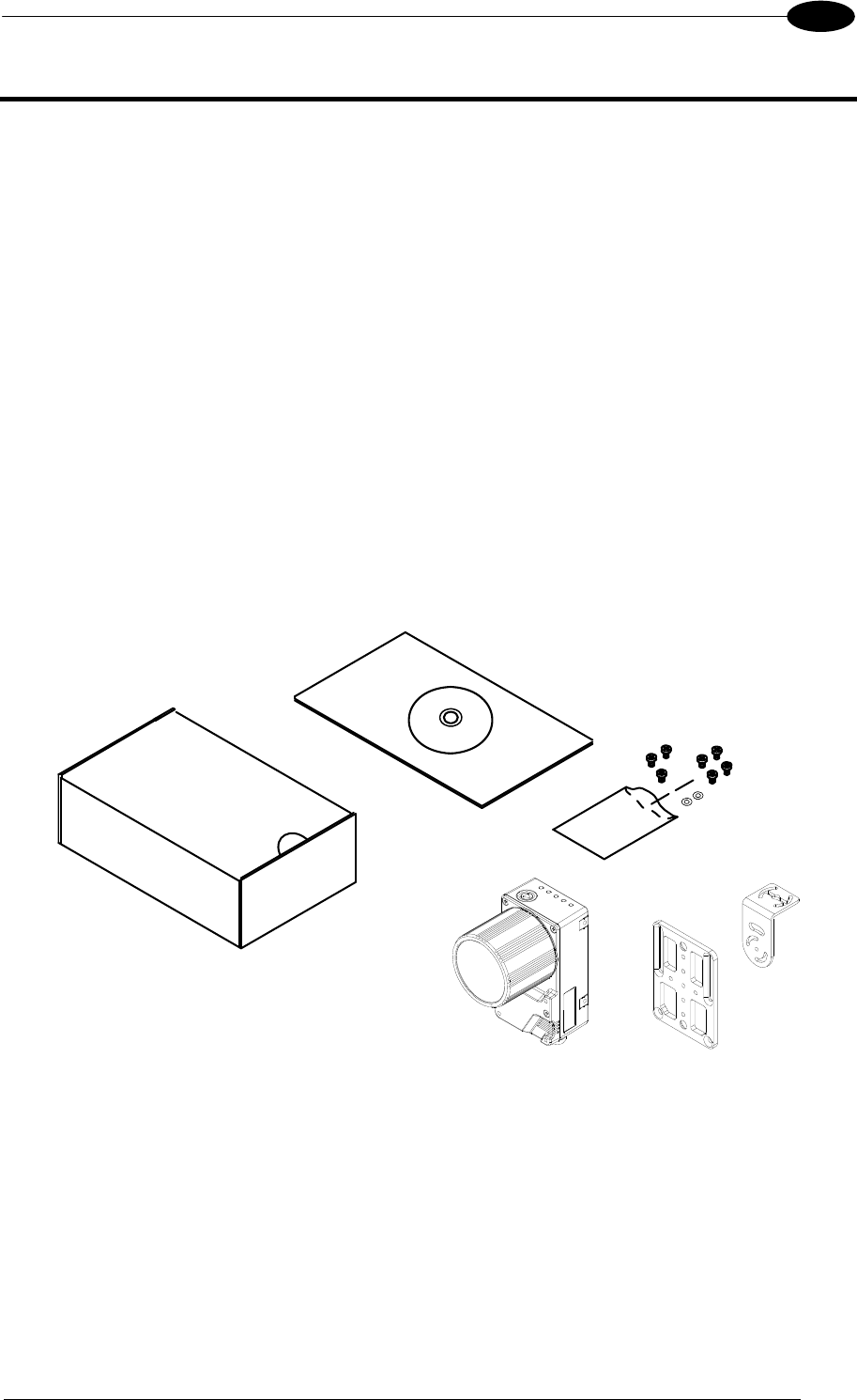
3.1 PACKAGE CONTENTS
Verify that the Matrix 400™ reader and all the parts supplied with the equipment are present
and intact when opening the packaging; the list of parts includes:
Matrix 400™ reader
Quick Reference Guide
Test Charts (2)
Matrix family CD-ROM
Mounting Kit
Mounting Screws (4 + 3)
Washers (2)
Mounting Brackets (2)
Figure 40 - Package Contents
MATRIX 400™ REFERENCE MANUAL
40
3
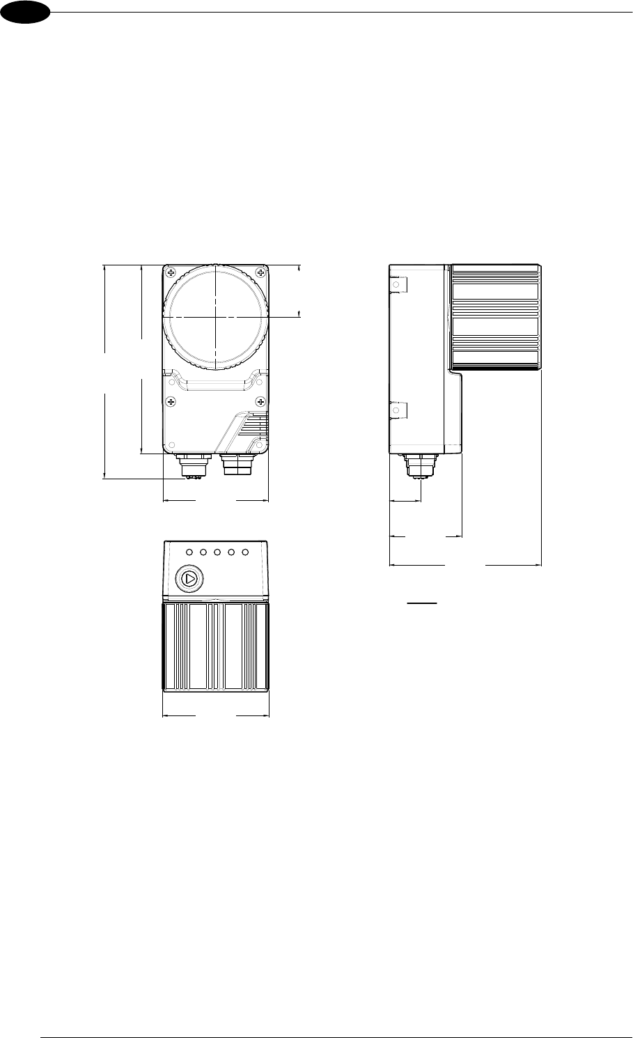
3.2 MECHANICAL DIMENSIONS
Matrix 400™ can be installed to operate in different positions. The twelve screw holes (M4 x
5) on the body of the reader are for mechanical fixture (Figure 41).
The diagram below gives the overall dimensions of the reader and may be used for its
installation.
Refer to par. 3.3 for various mounting solutions and correct positioning and par. 7.2 for FOV
vs. Reading Distance considerations.
109
[4.29]
60.5
[2.38]
123.2
[4.85]
41.5
[1.63]
87
[3.43]
18
[0.71]
30.25
[1.19]
Ø61
[Ø2.40]
Figure 41 - Overall Dimensions
mm
[in]
INSTALLATION
41
3
4
[0.16]
M4
[0.16] N°7
7
[0.28]
12.5
[0.49]
12.5
[0.49]
4.3
[0.17]
4.3
[0.17]
50
[1.97]
61
[2.40]
==
72.5
[2.85]
83.5
[3.29]
==
12.5
[0.49]
12.5
[0.49]
12.5
[0.49]
12.5
[0.49]
34
[1.34]
34
[1.34]
4.2
[0.17]
Ø8.25
[Ø0.32]
4.2
[0.17]
41.5
[1.63]
26.5
[1.04]
40
[1.57] =
=
3
[0.12]
50
[1.97]
70
[2.76]
==
4.2
[0.17]
8.5
[0.33]
Ø4.2
[Ø0.17]
45°
45°
15°
15°
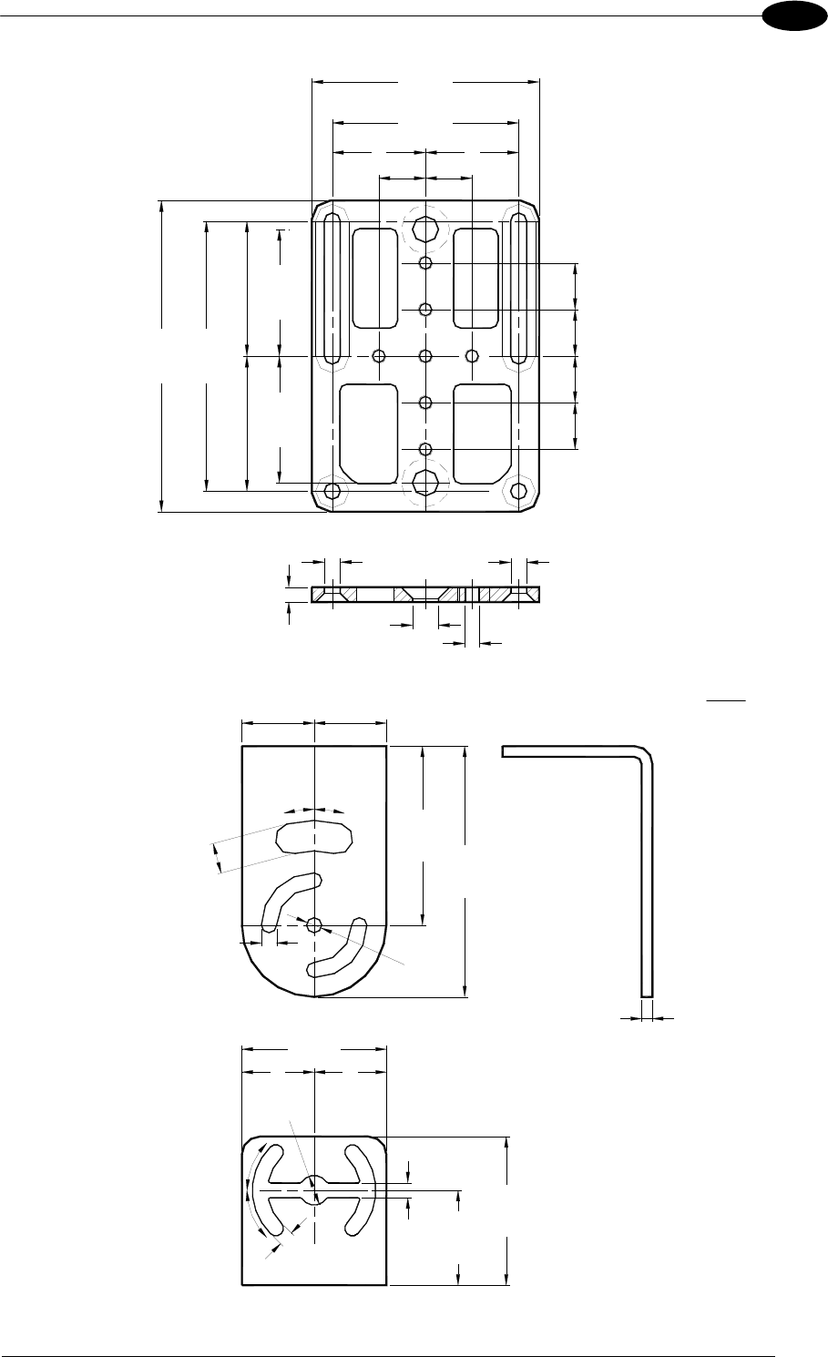
Figure 42 - Mounting Bracket Overall Dimensions
mm
[in]
MATRIX 400™ REFERENCE MANUAL
42
3
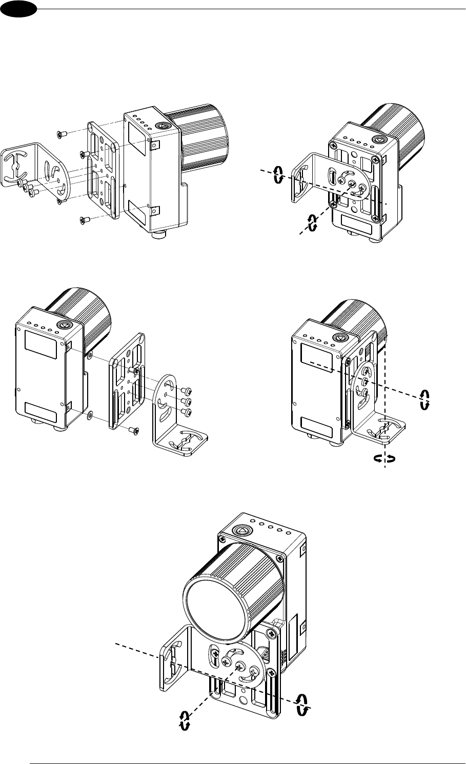
3.3 MOUNTING AND POSITIONING MATRIX 400™
Using the Matrix 400™ mounting brackets you can obtain rotation on the various axes of the
reader as shown in the diagram below:
Figure 43 –Positioning with Mounting Bracket (Back)
Figure 44 –Positioning with Mounting Bracket (Side)
Figure 45 –Positioning with Mounting Bracket (Front)
Tilt
Pitch
Skew
Pitch
Tilt
Pitch
INSTALLATION
43
3
Matrix 400™ is able to decode code labels at a variety of angles, however significant angular
distortion may degrade reading performance.
When mounting Matrix 400™, take into consideration these ideal label position angles: Pitch
or Skew 10° to 20° and Tilt 0°.
Note: Since Matrix 400™ is omni-directional on the code plane, the Pitch and Skew angles
have the same significance with respect to the code plane. However in some advanced code
reading applications performance can be improved by modifying the Skew angle.
Follow the suggestions below for the best orientation:
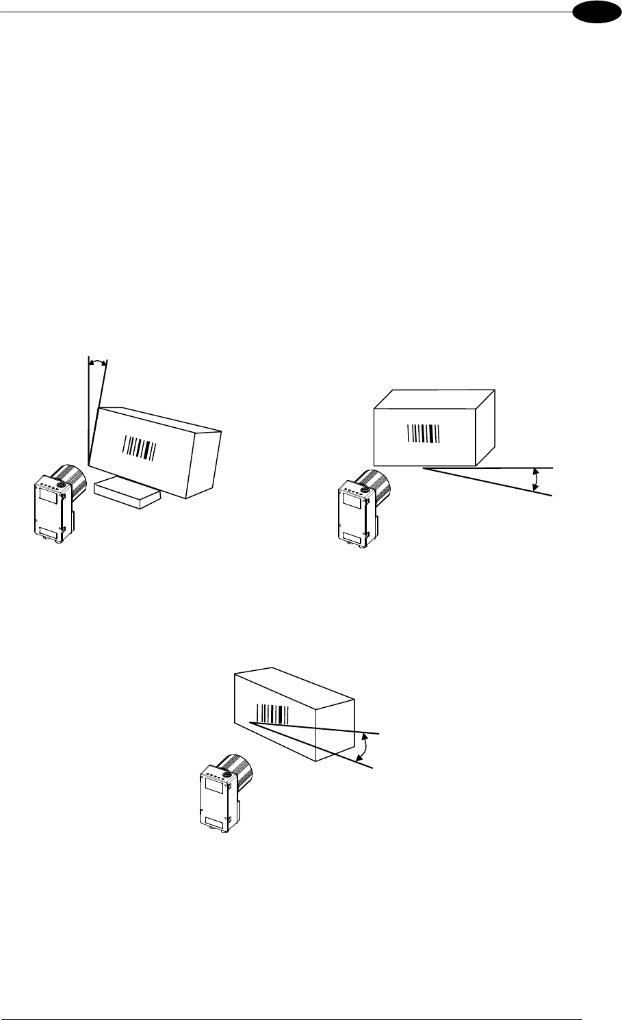
The Pitch and Skew angles are represented by the values P and S in Figure 46 and in Figure
47. Position the reader in order to avoid the direct reflection of the light emitted by the Matrix
400™ reader; it is advised to assure at least 10° for one of these angles. In some cases, such
as low contrast or low illumination, it can be useful to use a Pitch or Skew angle = 0°.
P
Minimize
Figure 46 - Pitch angle
S
Assure at least 10°
Figure 47 - Skew angle
The Tilt angle is represented by the value T in Figure 48. Matrix 400™ can read labels with
any tilt angle.
T
Minimize
Figure 48 - Tilt angle
See par. 7.2 for FOV vs. Reading Distance considerations.

MATRIX 400™ REFERENCE MANUAL
44
4
4 CBX ELECTRICAL CONNECTIONS
All Matrix 400™ models can be connected to a CBX connection box through one of the
available CAB-MSxx accessory cables. These accessory cables terminate in a 19-pin
connector on the Matrix 400™ side and in a 25-pin male D-sub connector on the CBX side.
We recommend making system connections through one of the CBX connection boxes since
they offer the advantages of easy connection, easy device replacement and filtered
reference signals.
NOTE
If you require direct wiring to the reader the details of the connector pins and
relative connections are indicated in Chaper 5.
The table below gives the pinout of the CBX100/500 terminal block connectors. Use this
pinout when the Matrix 400™ reader is connected by means of the CBX100/500:
CBX100/500 Terminal Block Connectors
Input Power
Vdc Power Supply Input Voltage +
GND Power Supply Input Voltage -
Earth Protection Earth Ground
Inputs
+V Power Source – External Trigger
I1A External Trigger A (polarity insensitive)
I1B External Trigger B (polarity insensitive)
-V Power Reference – External Trigger
+V Power Source – Inputs
I2A Input 2 A (polarity insensitive)
I2B Input 2 B (polarity insensitive)
-V Power Reference – Inputs
Outputs
+V Power Source - Outputs
-V Power Reference - Outputs
O1+ Output 1 +
O1- Output 1 -
O2+ Output 2 +
O2- Output 2 -
Auxiliary Interface
TX Auxiliary Interface TX
RX Auxiliary Interface RX
SGND Auxiliary Interface Reference
ID-NET™
REF Network Reference
ID+ ID-NET™ network +
ID- ID-NET™ network -
Shield Network Cable Shield
Main Interface
RS232 RS485
Full-Duplex
RS485
Half-Duplex
TX TX+ RTX+
RX *RX+
RTS TX- RTX-
CTS *RX-
SGND SGND SGND
* Do not leave floating, see par. 4.2.2 for connection details.
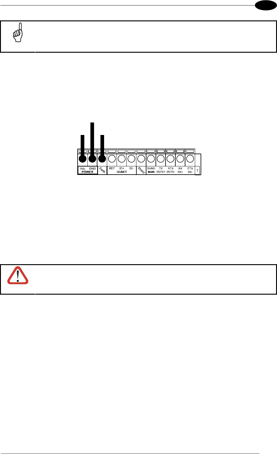
CBX ELECTRICAL CONNECTIONS
45
4
NOTE
To avoid electromagnetic interference when the reader is connected to a CBX
connection box, verify the jumper positions in the CBX as indicated in its Installation
Manual.
4.1 POWER SUPPLY
Power can be supplied to the reader through the CBX100/500 spring clamp terminal pins as
shown in Figure 49:
V+
in
Earth
Ground
Power Supply
VGND
Figure 49 - Power Supply Connections
The power must be between 10 and 30 Vdc only.
It is recommended to connect the device CHASSIS to earth ground (Earth) by setting the
appropriate jumper in the CBX connection box. See the CBX Installation Manual for details.
4.2 MAIN SERIAL INTERFACE
CAUTION
Do not connect to the Main Interface spring clamp terminals if using Host
Interface Modules with the CBX500.
The signals relative to the following serial interface types are available on the CBX spring
clamp terminal blocks.
The main serial interface type and its parameters (baud rate, data bits, etc.) can be
defined by the user via VisiSet™ software. The RS485 half duplex is automatically set
whenever MUX32 communication protocol is enabled. For more details refer to the
"Communication" folder in the VisiSet™ Help On Line.
Details regarding the connections and use of the interfaces are given in the next paragraphs.
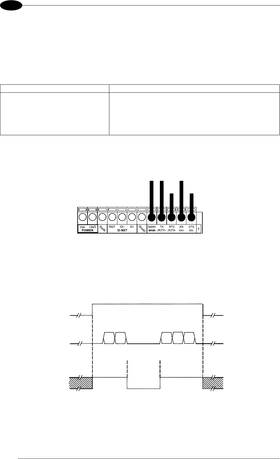
MATRIX 400™ REFERENCE MANUAL
46
4
4.2.1 RS232 Interface
The RS232 interface can be used for Point-to-Point, Pass Through or Master/Slave
connections. When it is connected to the host computer it allows both transmission of code
data and reader configuration by VisiSet™.
The following pins are used for RS232 interface connection:
CBX100/500 Function
TX Transmit Data
RX Receive Data
RTS Request To Send
CTS Clear To Send
SGND Signal Ground
It is always advisable to use shielded cables. The overall maximum cable length must be
less than 15 m (49.2 ft).
SGND RXD TXD
CTS RTS
USER INTERFACE
SGND TX RX
RTS CTS
READER
Figure 50 – RS232 Main Interface Connections Using Hardware Handshaking
The RTS and CTS signals control data transmission and synchronize the connected devices.
START
OF
TRANSMISSION
END
OF
TRANSMISSION
+ V
RTS
- V
+ V
TX DATA
- V
+ V
CTS
- V
DATA
TRANSMISSION
DATA
TRANSMISSION
C1 C2 C4
C3 C5
TRANSMISSION
STOPPED
ENABLED
DISABLED
ENABLED
IDLE IDLE
Figure 51 - RS232 Control Signals
If the RTS/CTS handshaking protocol is enabled, the Matrix 400™ activates the RTS output
to indicate a message is to be transmitted. The receiving unit activates the CTS input to
enable the transmission.
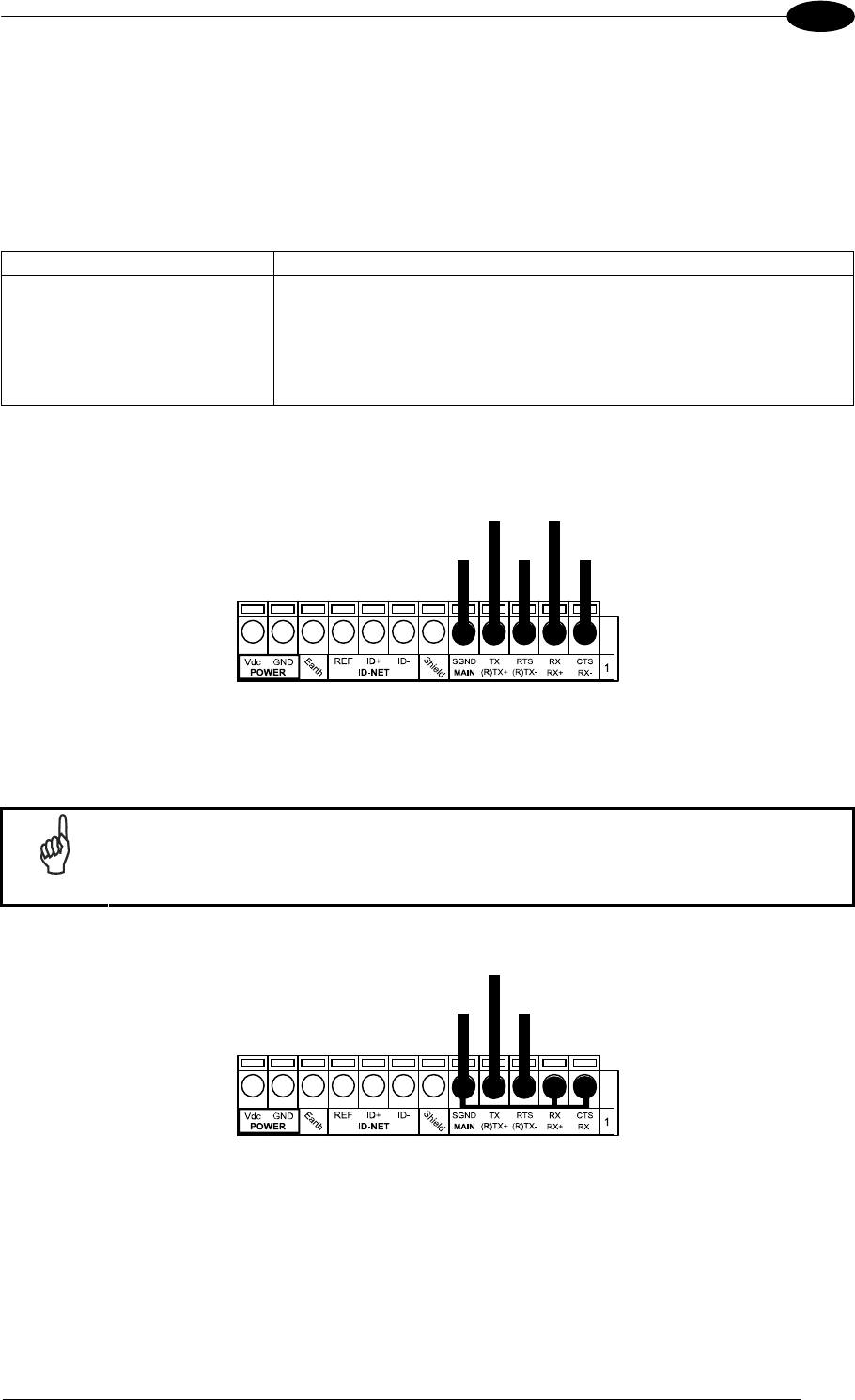
CBX ELECTRICAL CONNECTIONS
47
4
4.2.2 RS485 Full-Duplex Interface
The RS485 full-duplex (5 wires + shield) interface is used for non-polled communication
protocols in point-to-point connections over longer distances (max 1200 m / 3940 ft) than
those acceptable for RS232 communications or in electrically noisy environments.
The CBX pinout follows:
CBX100/500 Function
TX+ RS485 Transmit Data +
RX+ RS485 Receive Data +
TX- RS485 Transmit Data -
RX- RS485 Receive Data -
SGND Signal Ground
RX485+ TX485+
SGND RX485- TX485-
USER INTERFACE
SGND TX+ RX+
TX- RX-
READER
Figure 52 - RS485 Full-duplex Connections
NOTE
For applications that do not use RX485 signals, do not leave these lines
floating but connect them to SGND as shown below.
RX485+
SGND RX485-
USER INTERFACE
SGND TX+
TX-
READER
Figure 53 - RS485 Full-duplex Connections using Only TX Signals
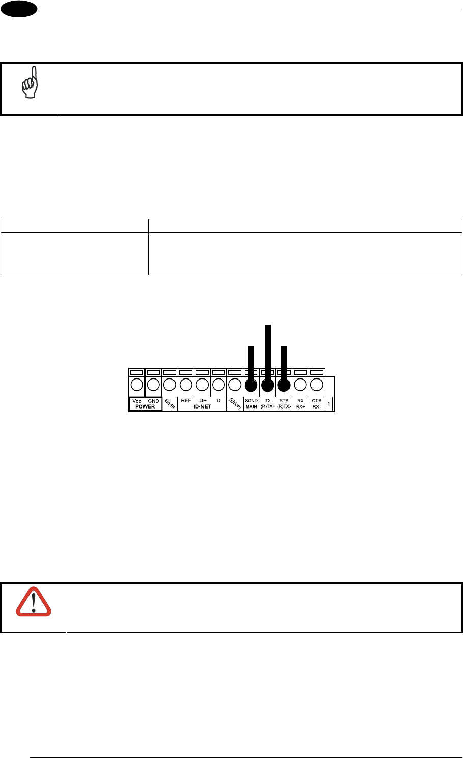
MATRIX 400™ REFERENCE MANUAL
48
4
4.2.3 RS485 Half-Duplex Interface
NOTE
This interface is provided for backward compatibility. We recommend using
the more efficient ID-NET™ network for Master/Slave or Multiplexer layouts.
The RS485 half-duplex (3 wires + shield) interface is used for polled communication
protocols.
It can be used for Multidrop connections with a Datalogic Multiplexer, (see par. 6.5) exploiting
a proprietary protocol based on polled mode called MUX32 protocol, where a master device
polls slave devices to collect data.
CBX100/500 Function
RTX+ RS485 Receive/Transmit Data +
RTX- RS485 Receive/Transmit Data -
SGND Signal Ground
RTX485+
SGND RTX485-
USER INTERFACE
SGND RTX+
RTX-
READER
Figure 54 - RS485 Half-duplex Connections
This interface is forced by software when the protocol selected is MUX32 protocol.
In a Multiplexer layout, the Multidrop address must also be set via serial channel by the
VisiSet™ utility or by the Host Programming Mode.
Figure 55 shows a multidrop configuration with Matrix 400™ readers connected to a
Multiplexer.
CAUTION
This is an example of multidrop wiring. Consult the multiplexer manual for
complete wiring instructions.
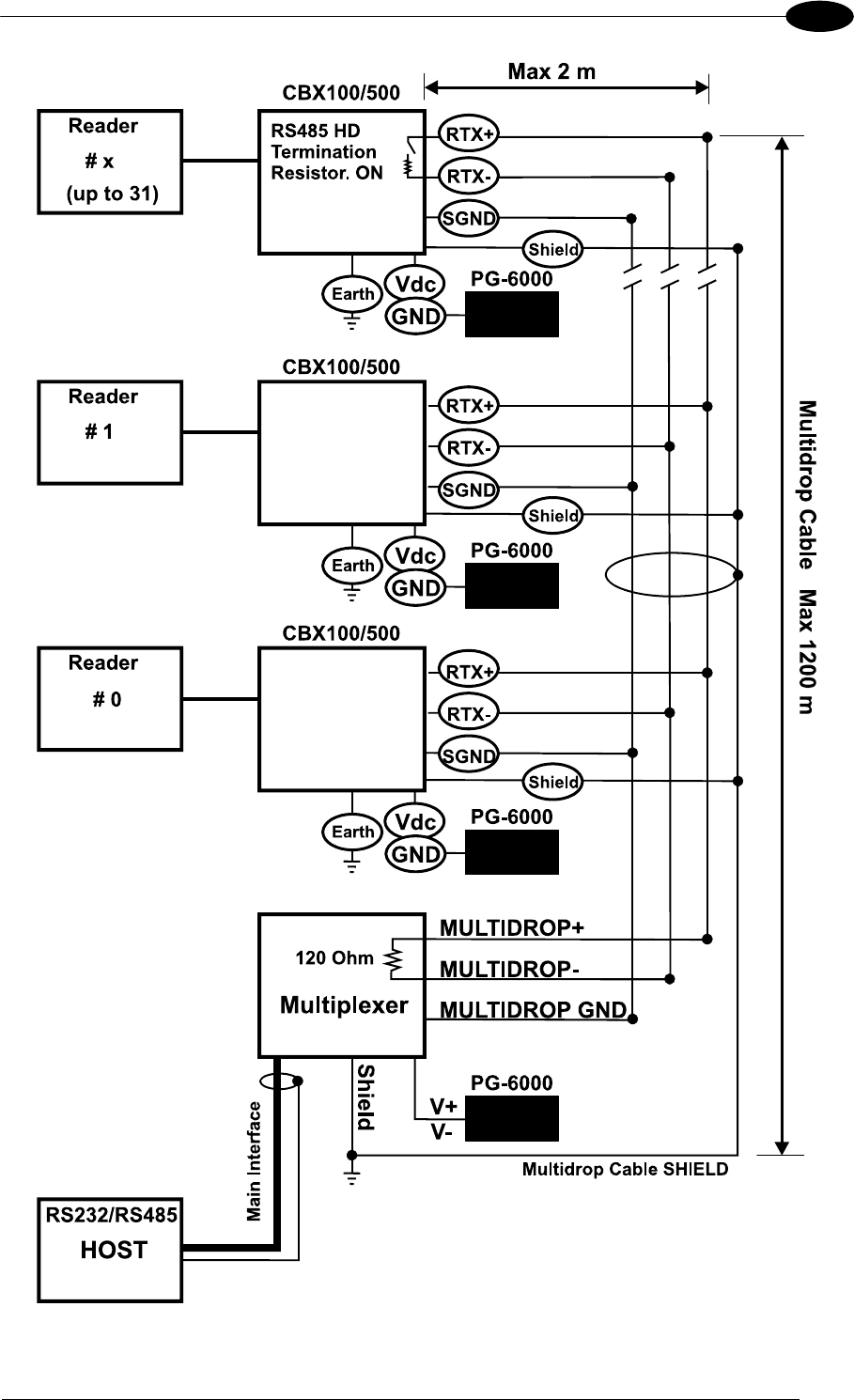
CBX ELECTRICAL CONNECTIONS
49
4
Figure 55 - Matrix 400™ Multidrop Connection to a Multiplexer

MATRIX 400™ REFERENCE MANUAL
50
4
4.3 ID-NET™ INTERFACE
CBX100/500 Function
Shield Network Cable Shield
ID+ ID-NET™ network +
ID- ID-NET™ network -
REF Network Reference
4.3.1 ID-NET™ Cables
The following instructions are referred to Figure 57, Figure 58 and Figure 59.
The general cable type specifications are: CAT5 twisted pair + additional CAT5 twisted
pair, shielded cable AWG 24 (or AWG 22) stranded flexible.
We recommend using DeviceNet cables (drop or trunk type) to the following reference
standards:
AN50325 – IEC 62026
UL STYLE 2502 80°C 30V
Cable Shield MUST be connected to earth ground ONLY at the Master.
NEVER use ID-NET™ cable shield as common reference.
The ID-NET™ max cable length depends on the baudrate used, (see the Baudrate Table
below).
For Common Power Connections use only 2 wires (ID+ and ID-).
- DC Voltage Power cable (Vdc – GND) should be handled as a signal cable (i.e. do
not put it together with AC cable):
- Wire dimensioning must be checked in order to avoid voltage drops greater than 0.8
Volts.
- Cable should lie down as near as possible to the ID-NET™ cable (avoiding wide
loops between them).
Reader's chassis may be connected to earth.
Network inside the same building.
Baudrate Table
Baud Rate 125 kbps 250 kbps 500 kbps 1Mbps
Cable Length 1200 m 900 m 700 m *
* Application dependent, contact your Datalogic Automation representative for details.
NOTE
The default ID-NET™ baudrate is 500 kbps. Lower ID-NET™ baudrates
allow longer cable lengths. The baudrate is software configurable by
authorized Datalogic Automation personnel only.
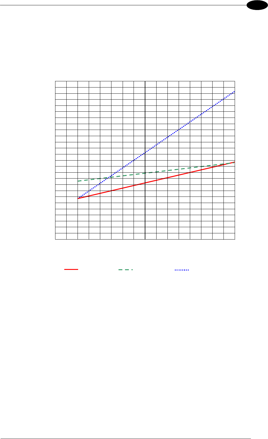
CBX ELECTRICAL CONNECTIONS
51
4
4.3.2 ID-NET™ Response Time
The following figure shows the response time of the ID-NET™ network. This time is defined
as the period between the Trigger activation and the beginning of data transmission to the
Host.
Max ID-NET™ Response Time
240
220
200
180
160
140
120
100
80
60
40
20
0
Response Time (ms)
Number of Nodes
500 kbps 250 kbps 125 kbps
0 1 2 3 4 5 6 7 8 9 10 11 12 13 14 15 16
Figure 56 – ID-NET™ Response Time
CONDITIONS:
ID-NET™ M/S Synchronized layout
message length = 50 bytes per node
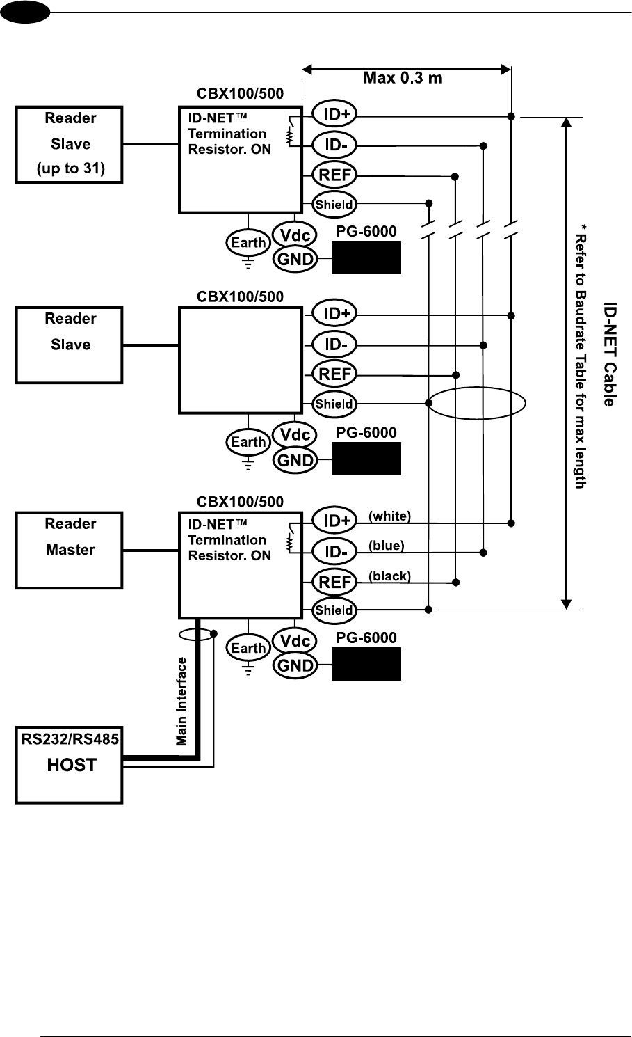
MATRIX 400™ REFERENCE MANUAL
52
4
Figure 57 – ID-NET™ Network Connections with isolated power blocks
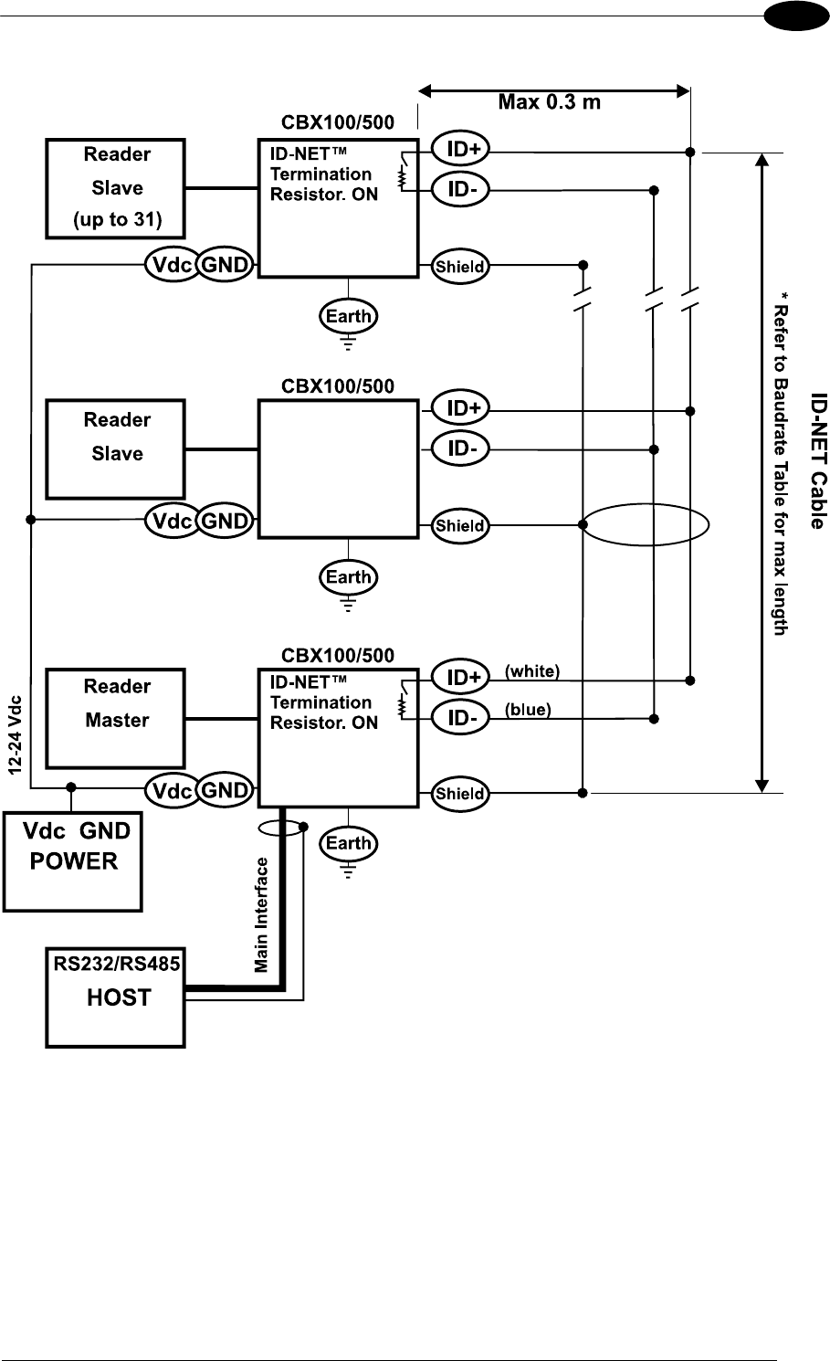
CBX ELECTRICAL CONNECTIONS
53
4
Figure 58 - ID-NET™ Network Connections with Common Power Branch Network
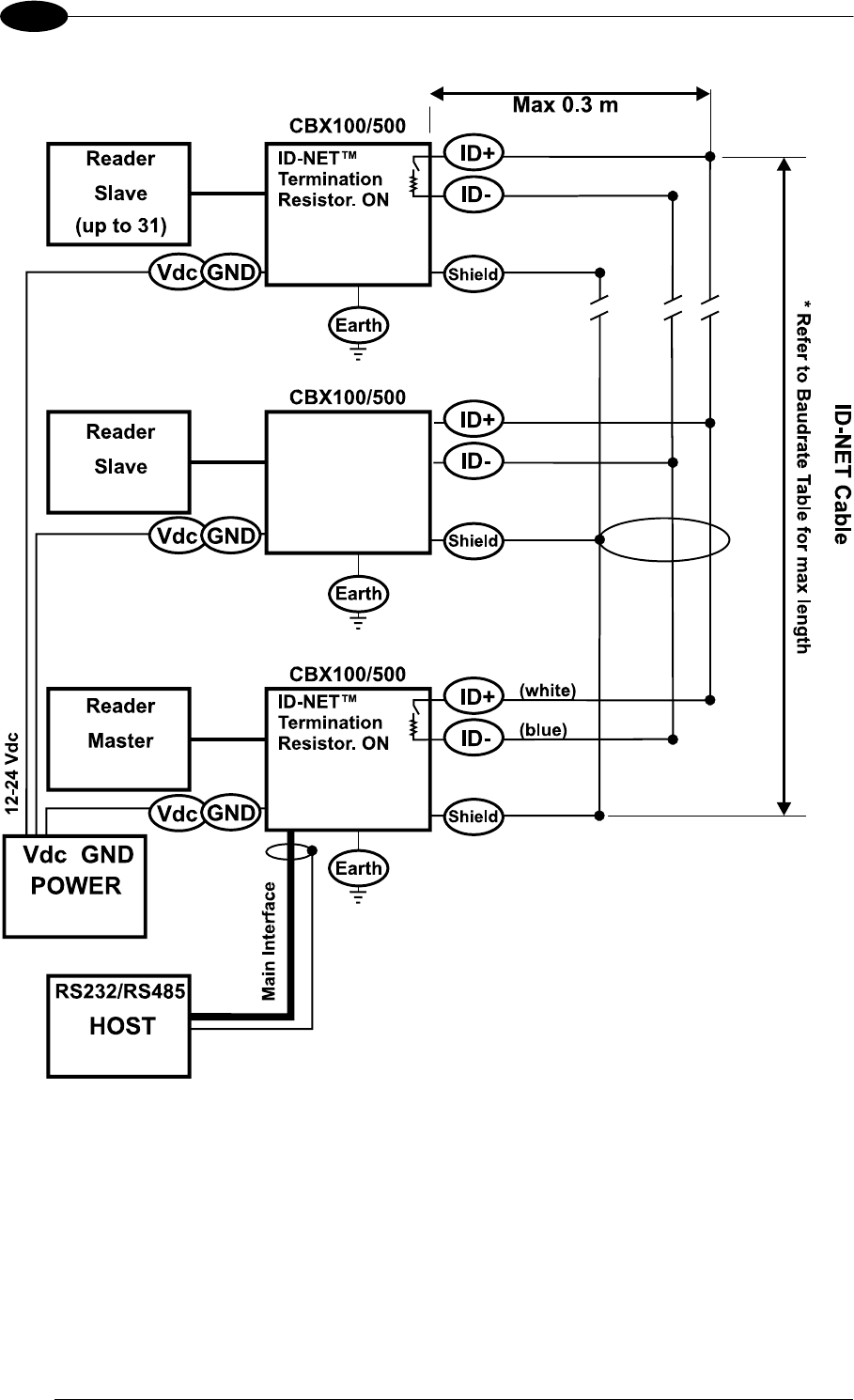
MATRIX 400™ REFERENCE MANUAL
54
4
Figure 59 – ID-NET™ Network Connections with Common Power Star Network
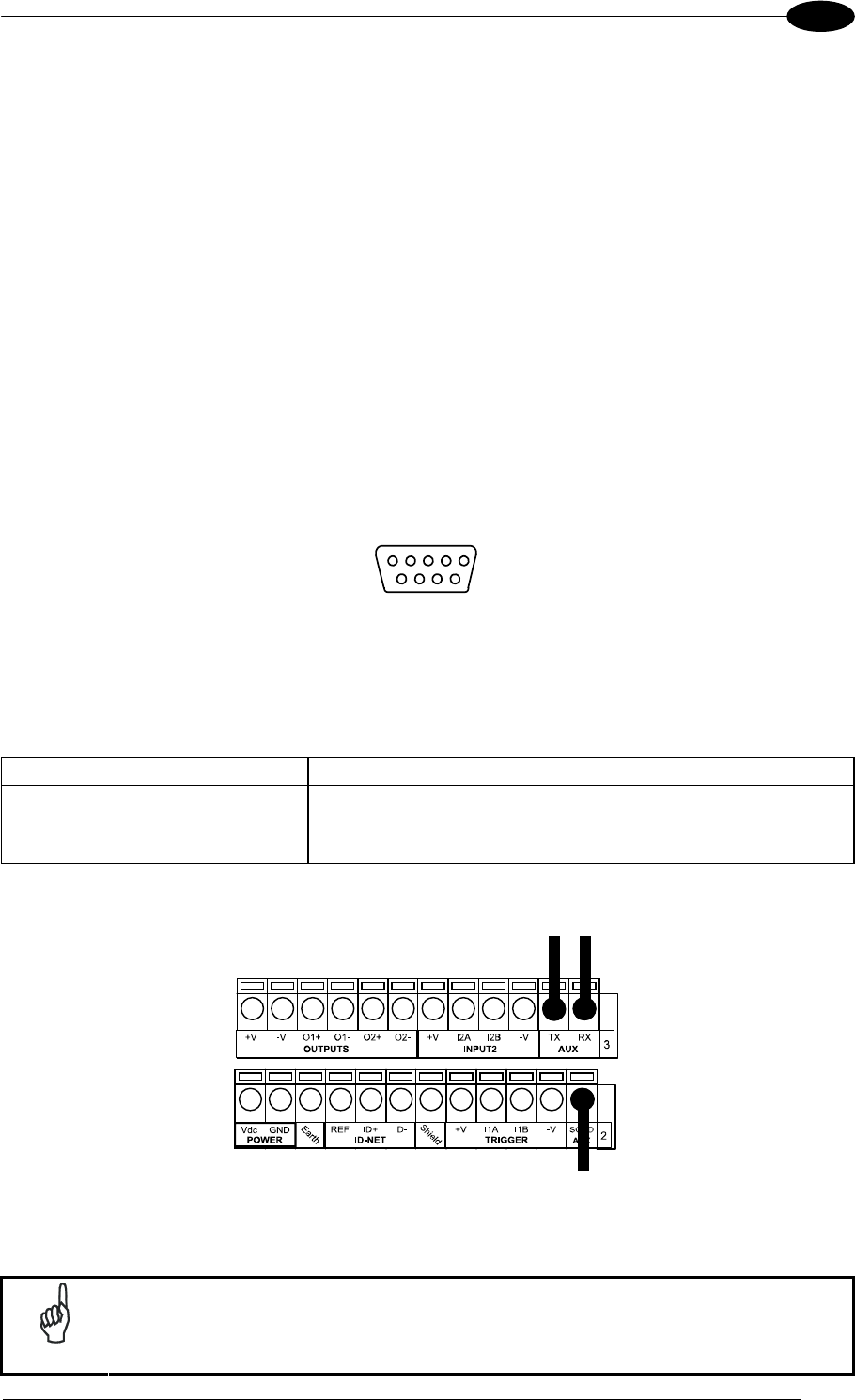
CBX ELECTRICAL CONNECTIONS
55
4
4.3.3 ID-NET™ Network Termination
The network must be properly terminated in the first and last reader of the network. This is
done by setting the ID-NET™ Termination Resistance Switch in the CBX100/500 to ON.
4.4 AUXILIARY RS232 INTERFACE
The RS232 auxiliary interface is available for Point-to-Point, Pass Through or Master/Slave
connections. When it is connected to the host computer it allows both transmission of code
data and reader configuration by VisiSet™.
The parameters relative to the aux interface (baud rate, data bits, etc.) as well as particular
communication modes such as LOCAL ECHO can be defined through the Communication
folder of the VisiSet™ utility program.
The 9-pin female Auxiliary Interface connector inside the CBX is the preferred connector for
device configuration or communication monitoring.
51
69
Figure 60 - 9-pin female connector
If permanent system wiring is required, the following pins are used to connect the RS232
auxiliary interface:
CBX100/500 Function
RX Auxiliary Interface Receive Data
TX Auxiliary Interface Transmit Data
SGND Auxiliary Interface Reference
RX TX
Reference
USER INTERFACE
Figure 61 - RS232 Auxiliary Interface Connections
NOTE
Do not connect the Aux Interface to the CBX spring clamp connectors and
the 9-pin connector simultaneously.

MATRIX 400™ REFERENCE MANUAL
56
4
4.5 INPUTS
There are two optocoupled polarity insensitive inputs available on the reader: Input 1
(External Trigger) and Input 2, a generic input:
The External Trigger can be used in One Shot Mode or in Phase Mode. Its main functions
are:
acquisition trigger in One Shot Mode
reading phase-ON/reading phase-OFF command in Phase Mode
The main functions of the general purpose Input 2 are:
second external trigger in Phase Mode
match code storage command when the Match Code option is enabled
The electrical features of both inputs are:
VAB = 30 Vdc max.
IIN = 10 mA (reader) + 12 mA (CBX) max.
The active state of these inputs are selected in software. Refer to the VisiSet™ Help On
Line.
An anti-disturbance filter is implemented in software on both inputs so that the minimum
pulse duration is 0.5 milliseconds. This value can be increased through the software
parameter Debounce Filter, see the Digital I/O folder in the VisiSet™ Help On Line for further
details.
These inputs are optocoupled and can be driven by both NPN and PNP type commands.
NOTE
Polarity insensitive inputs assure full functionality even if pins A and B are
exchanged.
The connections are indicated in the following diagrams:
CBX100/500 Function
+V Power Source - External Trigger
I1A External Trigger A (polarity insensitive)
I1B External Trigger B (polarity insensitive)
-V Power Reference - External Trigger
The yellow Trigger LED (Figure 19, 5) is on when the active state of the External Trigger
corresponds to ON.
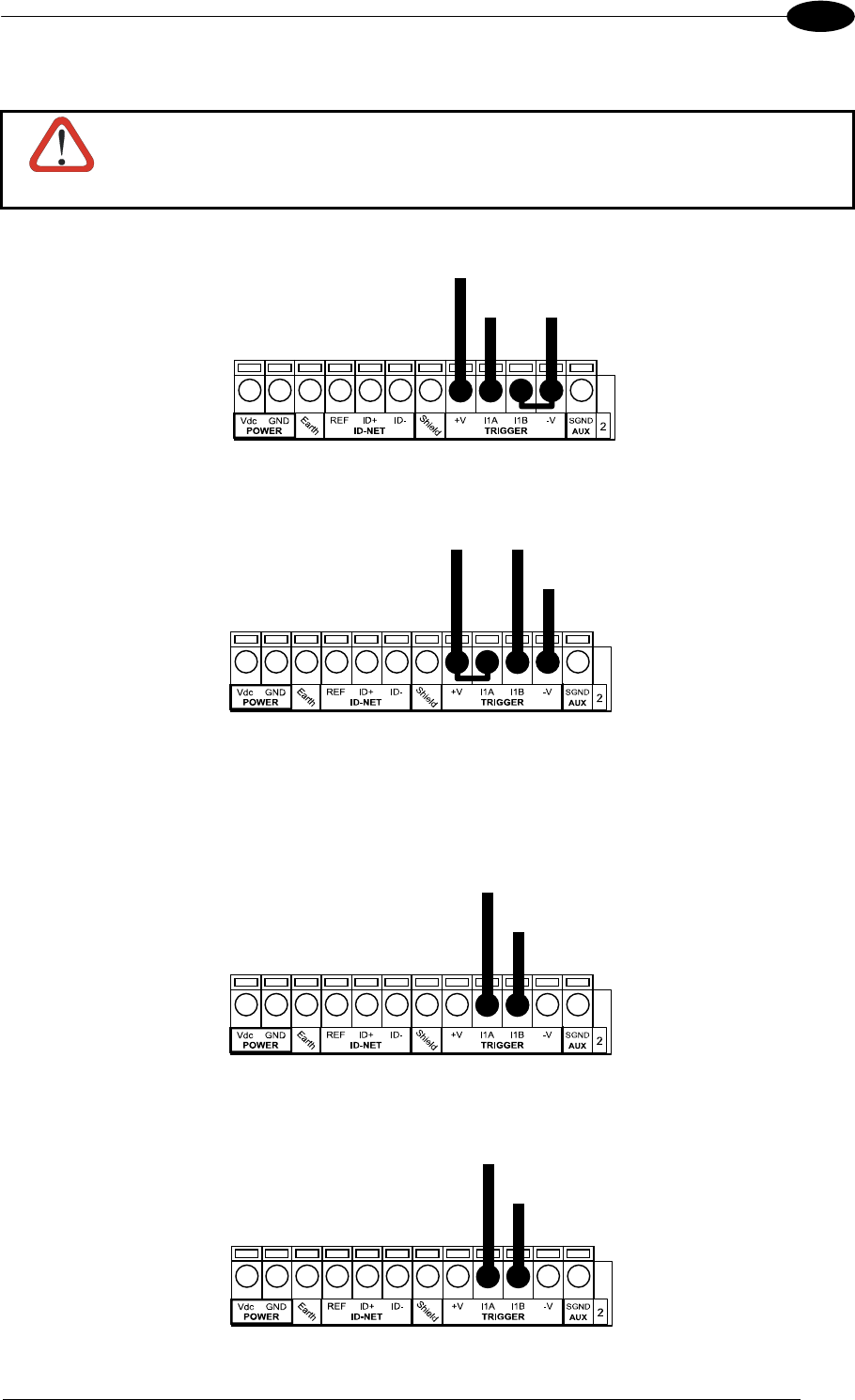
CBX ELECTRICAL CONNECTIONS
57
4
EXTERNAL TRIGGER INPUT CONNECTIONS USING MATRIX 400™ POWER
CAUTION
Power is available directly to the Input Device, independently from the Power
Supply Switch inside the CBX.
(brown)
(black) (blue)
PH-1 Photocell (PNP)
Figure 62 – PH-1 External Trigger Using MATRIX 400™ Power
Power to Input
Photocell Signal
Photocell
Reference
NPN Photocell
Figure 63 - NPN External Trigger Using MATRIX 400™ Power
EXTERNAL TRIGGER INPUT CONNECTIONS USING EXTERNAL POWER
Pulled down to External
Input Device Reference
Input
Signal
PNP Photocell
Figure 64 - PNP External Trigger Using External Power
Pulled up to External
Input Device Power
Input
Signal
NPN Photocell
Figure 65 - NPN External Trigger Using External Power
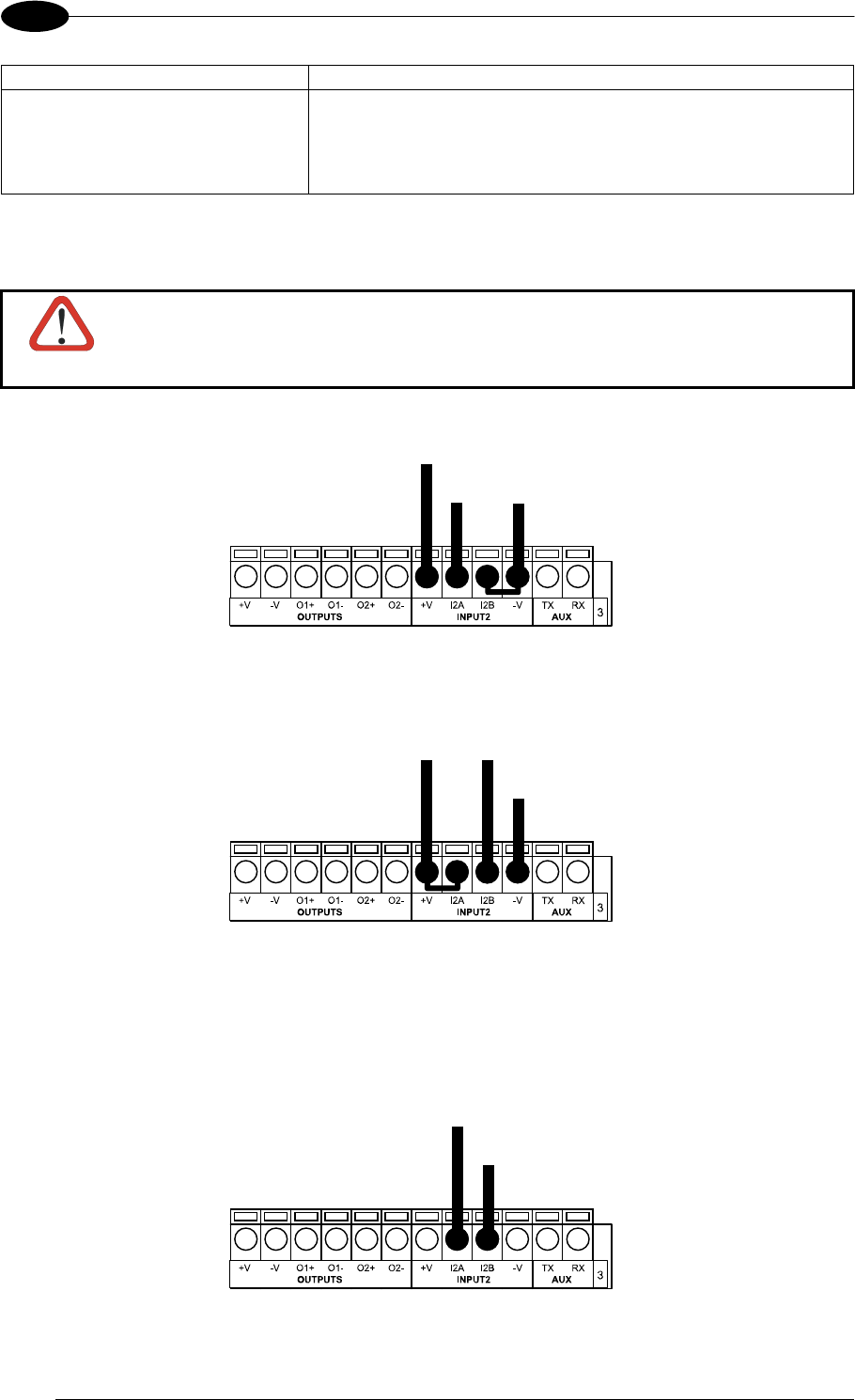
MATRIX 400™ REFERENCE MANUAL
58
4
CBX100/500 Function
+V Power Source - Inputs
I2A Input 2 A (polarity insensitive)
I2B Input 2 B (polarity insensitive)
-V Power Reference - Inputs
INPUT 2 CONNECTIONS USING MATRIX 400™ POWER
CAUTION
Power is available directly to the Input Device, independently from the Power
Supply Switch inside the CBX.
Power to
Input Device
Input Input Device
Signal Reference
Input Device
PNP Input 2 Using MATRIX 400™ Power
Power to Input
Input Device Signal
Input Device
Reference
Input Device
NPN Input 2 Using MATRIX 400™ Power
INPUT 2 CONNECTIONS USING EXTERNAL POWER
Pulled down to External
Input Device Reference
Input
Signal
Input Device
Figure 66 - PNP Input 2 Using External Power
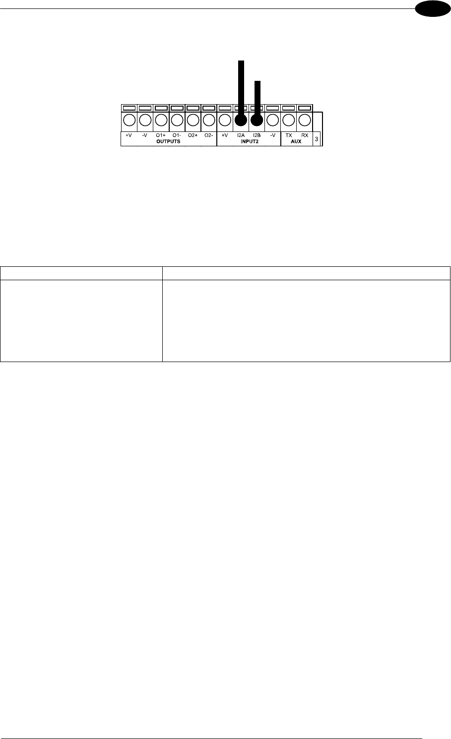
CBX ELECTRICAL CONNECTIONS
59
4
Pulled up to External
Input Device Power
Input
Signal
Input Device
Figure 67 - NPN Input 2 Using External Power
4.6 OUTPUTS
Two optocoupled general purpose outputs are available. The meaning of the two outputs
Output 1 and Output 2 can be defined by the user. They are typically used either to signal the
data collection result or to control an external lighting system.
CBX100/500 Function
+V Power Source - Outputs
O1+ Output 1 +
O1- Output 1 -
O2+ Output 2 +
O2- Output 2 -
-V Power Reference Outputs
The electrical features of the two outputs are the following:
VCE = 30 Vdc max.
ICE = 40 mA continuous max.; 130 mA pulsed max.
VCE saturation = 1 Vdc max. @ 10 mA
PD = 80 mW Max. @ 45 °C ambient temp.
By default, Output 1 is associated with the Partial Read and No Read events, which activates
when the code(s) signaled by the external trigger are not decoded, and Output 2 is
associated with the Complete Read event, which activates when all the selected codes are
correctly decoded.
The output signals are fully programmable being determined by the configured
Activation/Deactivation events, Deactivation Timeout or a combination of the two. Refer to
the Digital I/O folder in the VisiSet™ Help On Line for further details.
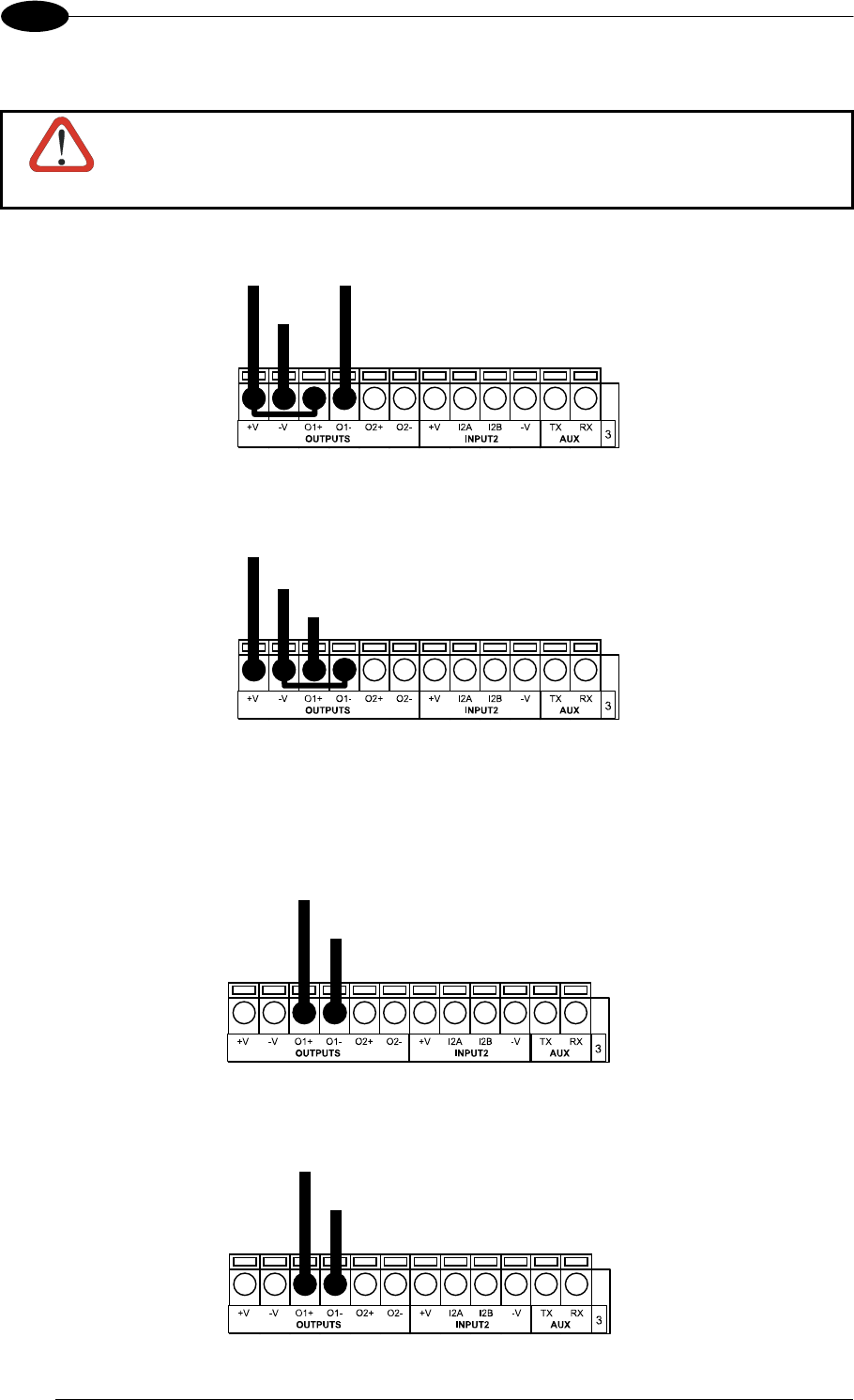
MATRIX 400™ REFERENCE MANUAL
60
4
OUTPUT CONNECTIONS USING MATRIX 400™ POWER
CAUTION
Power is available directly to the Output Device, independently from the
Power Supply Switch inside the CBX.
Power to Output
Output device Signal
Output device
Reference
Output Device
Figure 68 - Open Emitter Output Using MATRIX 400™ Power
Power to
Output device
Output device
Reference
Output Device
Output
Signal
Figure 69 - Open Collector Output Using MATRIX 400™ Power
OUTPUT CONNECTIONS USING EXTERNAL POWER
Pulled up to External
Output Device Power
Output
Signal
Output Device
Figure 70 - Output Open Emitter Using External Power
Pulled down to External
Output Device Reference
Output
Signal
Output Device
Figure 71 - Output Open Collector Using External Power
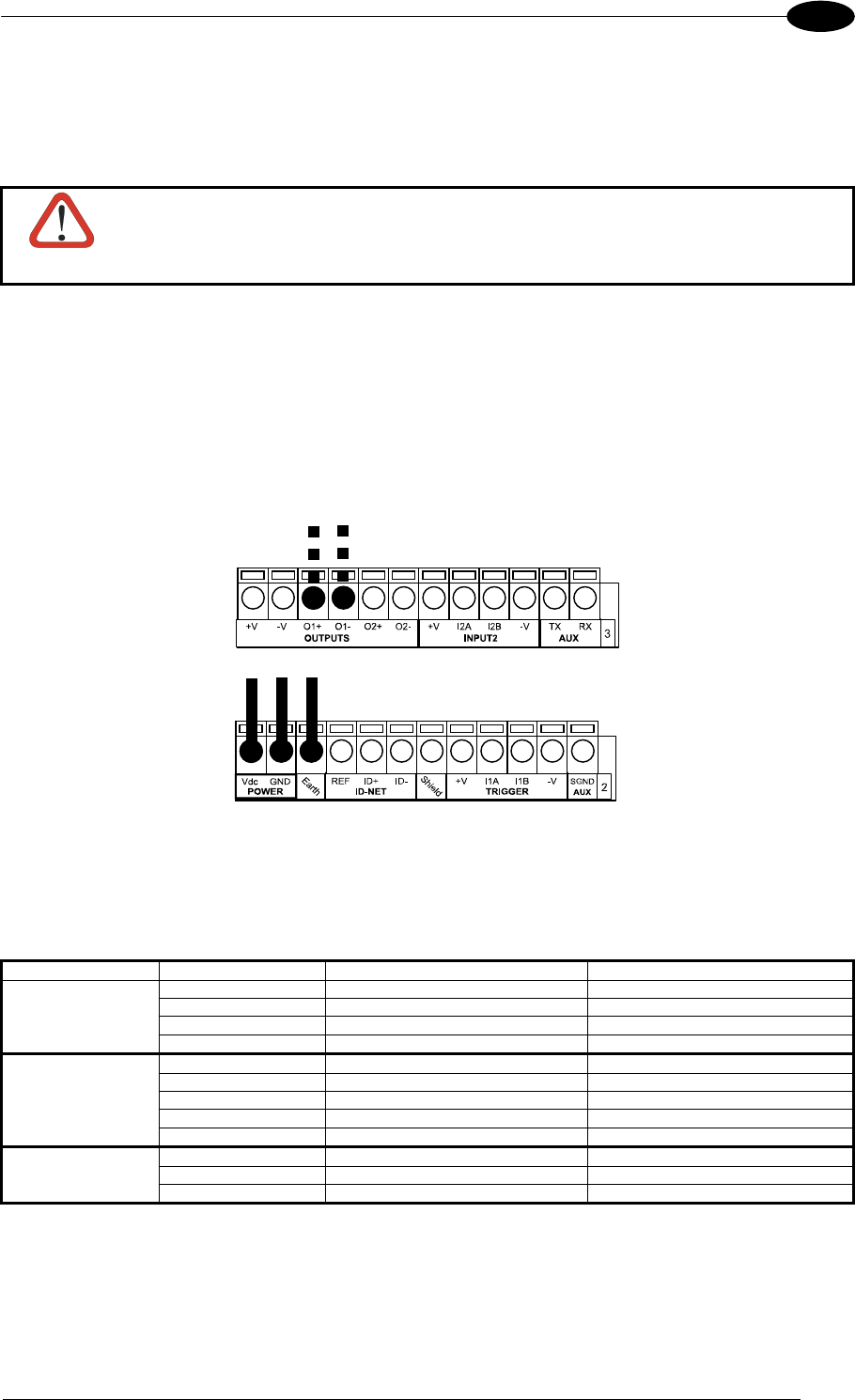
CBX ELECTRICAL CONNECTIONS
61
4
4.7 EXTERNAL LIGHTING SYSTEMS
If an External Illuminator is used, it can be powered from the CBX connection box. It must be
connected to the Vdc and GND terminal clamps.
CAUTION
Power is available directly to the Illuminator, independently from the Power
Supply Switch inside the CBX.
In the case of the LT-100, LT-200 or LT-300 illuminators, one of the available digital outputs
must be connected as the control signal. In VisiSet™, configure the Output Line Function
parameter to "External Lighting System" and the Matrix Output x External Lighting System
Mode parameter to "Triggered".
Control Signal for
LT-100, LT-200 or
LT-300 illuminators
Power to External
Illuminator
Figure 72 – External Lighting System Connections
Below is a table summarizing the various External Illuminator wiring and power requirements:
Illuminator Wire Color CBX/Matrix Signal Meaning
LT-100 Red Vdc 10 to 30 Vdc
LT-200 Black GND Ground
Blue O1- or O2- Control Signal -
White O1+ or O2+ Control Signal +
LT-300 Brown Vdc 10 to 30 Vdc
Black GND Ground
Yellow/Green Earth Shield/Earth Ground
Blue O1- or O2- Control Signal -
White O1+ or O2+ Control Signal +
LT-210, LT-314, White Vdc 24 Vdc
LT-316, LT-410 Black GND Ground
LT-510, LT-511 Shield Earth Shield/Earth Ground

MATRIX 400™ REFERENCE MANUAL
62
4
4.8 USER INTERFACE - HOST
The following table contains the pinout for standard RS232 PC Host interface. For other user
interface types please refer to their own manual.
RS232 PC-side connections
1 5
9 6
9-pin male connector
13
25 14
1
25-pin male connector
Pin Name Pin Name
2 RX 3 RX
3 TX 2 TX
5 GND 7 GND
7 RTS 4 RTS
8 CTS 5 CTS
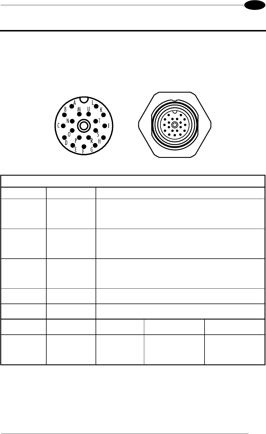
19-PIN CONNECTOR ELECTRICAL CONNECTIONS
63
5
5 MATRIX 400™ CONNECTOR ELECTRICAL CONNECTIONS
5.1 M16 19-PIN CONNECTOR
The Matrix 400™ reader is equipped with an M16 19-pin male connector (Binder, 423
Series) for connection to the power supply, serial interfaces and input/output signals. The
details of the connector pins are indicated in the following table:
Figure 73 – M16 19-pin Male Connector
19-pin M16 male connector pinout
Pin Name Function
A Vdc Power supply input voltage +
L GND Power supply input voltage -
K CHASSIS
Cable shield internally connected by capacitor to the
chassis
B I1A External Trigger A (polarity insensitive)
C I1B External Trigger B (polarity insensitive)
D I2A Input 2 A (polarity insensitive)
E I2B Input 2 B (polarity insensitive)
H O1+ Output 1 +
F O1- Output 1 -
G O2+ Output 2 +
I O2- Output 2 -
S RX Auxiliary RS232 RX
O TX Auxiliary RS232 TX
R ID+ ID-NET™ network +
P ID- ID-NET™ network -
Pin Name RS232 RS485
Full-Duplex
RS485
Half-Duplex
M TX TX+ RTX+
U RX *RX+
N RTS TX- RTX-
T
MAIN
INTERFACE
(SW
SELECTABLE) CTS *RX-
* Do not leave floating, see par. 5.4.2 for connection details.
In order to meet EMC requirements:
connect the reader chassis to the plant earth ground by means of a flat copper braid
shorter than 100 mm;
connect the main interface cable shield to pin K of the 19-pin connector;
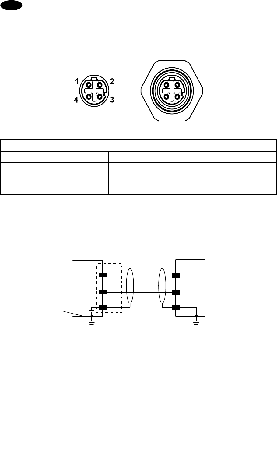
MATRIX 400™ REFERENCE MANUAL
64
5
5.2 M12-D 4-PIN CONNECTOR (ETHERNET)
In Matrix 400 xxx-x1x models, an M12 D-Coded connector is provided for the on-board
Ethernet connection. This interface is IEEE 802.3 10 BaseT and IEEE 802.3u 100 BaseTx
compliant. See par. 5.7 for connection details.
Figure 74 - M12 D-Coded Female Ethernet Network Connector
M12 D-Coded Ethernet Network Connector pinout
Pin Name Function
1 TX + Transmitted data (+)
2 RX + Received data (+)
3 TX - Transmitted data (-)
4 RX - Received data (-)
5.3 POWER SUPPLY
Power is supplied to the reader through the pins provided on the M16 19-pin connector (see
Figure 75):
MATRI
X
A
L
Vdc
GND
K
SHIELD
USER INTERFACE
CHASSIS
V- (Ground)
V+ (10 - 30 Vdc)
Earth Ground Earth Ground
Chassis
Figure 75 - Power Supply Connection
The allowed supply voltage range is 10 to 30 Vdc.
5.4 MAIN SERIAL INTERFACE
The signals relative to the following serial interface types are available on the M16 19-pin
connector:
The main serial interface type and its parameters (baud rate, data bits, etc.) can be
defined by the user via VisiSet™ software. The RS485 half duplex is automatically set
whenever MUX32 communication protocol is enabled. For more details refer to the
"Communication" folder in the VisiSet™ Help On Line.
Details regarding the connections and use of the interfaces are given in the next paragraphs.
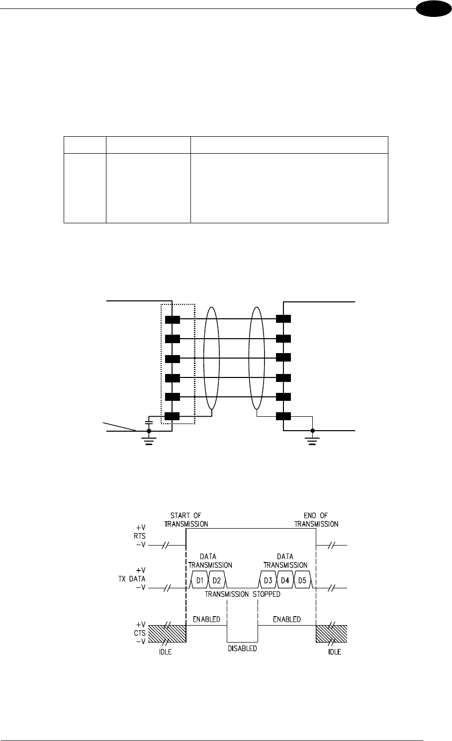
19-PIN CONNECTOR ELECTRICAL CONNECTIONS
65
5
5.4.1 RS232 Interface
The RS232 interface can be used for Point-to-Point, Pass Through or Master/Slave
connections. When it is connected to the host computer it allows both transmission of code
data and reader configuration by VisiSet™.
The following pins of the M16 19-pin connector are used for RS232 interface connection:
Pin Name Function
M TX Transmit Data
U RX Receive Data
N RTS Request To Send
T CTS Clear To Send
L GND Ground
It is always advisable to use shielded cables. The overall maximum cable length must be
less than 15 m (49.2 ft).
MATRI
X
GND
RTS
CTS
RX
TX
USER INTERFACE
Reference Ground
Handshaking
Signals
TXD
RXD
SHIELD
L
N
T
U
M
K
Earth Ground Earth Ground
Chassis
Figure 76 - RS232 Main Interface Connections
The RTS and CTS signals control data transmission and synchronize the connected devices.
Figure 77 - RS232 Control Signals
If the RTS/CTS handshaking protocol is enabled, Matrix 400™ activates the RTS output to
indicate a message is to be transmitted. The receiving unit activates the CTS input to enable
the transmission.
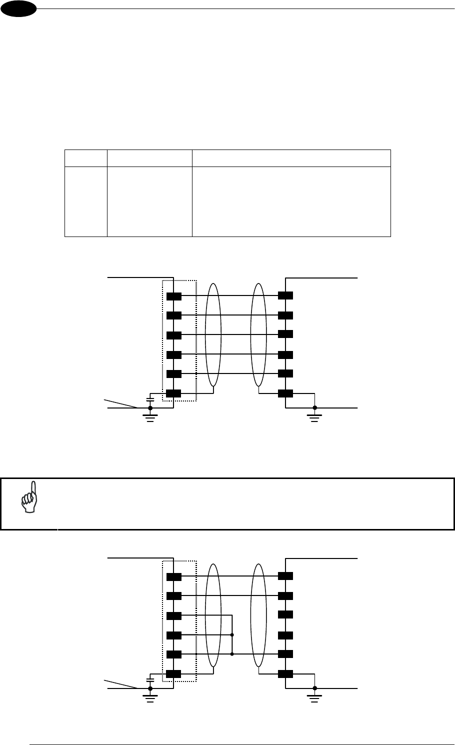
MATRIX 400™ REFERENCE MANUAL
66
5
5.4.2 RS485 Full-Duplex Interface
The RS485 full-duplex (5 wires + shield) interface is used for non-polled communication
protocols in point-to-point connections over longer distances (max 1200 m / 3940 ft) than
those acceptable for RS232 communications or in electrically noisy environments.
The following pins of the M16 19-pin connector are used for RS485 full-duplex
communication:
Pin Name Function
M TX+ RS485 Transmit Data (+)
N TX- RS485 Transmit Data (-)
U RX+ RS485 Receive Data (+)
T RX- RS485 Receive Data (-)
L GND Ground
MATRI
X
GND
RX+
RX-
TX-
TX+
USER INTERFACE
TX485
RX485
SHIELD
Reference Ground
L
U
T
N
M+
K
-
+
-
Earth Ground Earth Ground
Chassis
Figure 78 - RS485 Full-duplex Connections
NOTE
For applications that do not use RX485 signals, do not leave these lines
floating but connect them to GND as shown below.
MATRI
X
GND
RX+
RX-
TX-
TX+
USER INTERFACE
RX485
SHIELD
Reference Ground
L
U
T
N
M+
K
-
Earth Ground Earth Ground
Chassis
Figure 79 - RS485 Full-duplex Connections using Only TX Signals
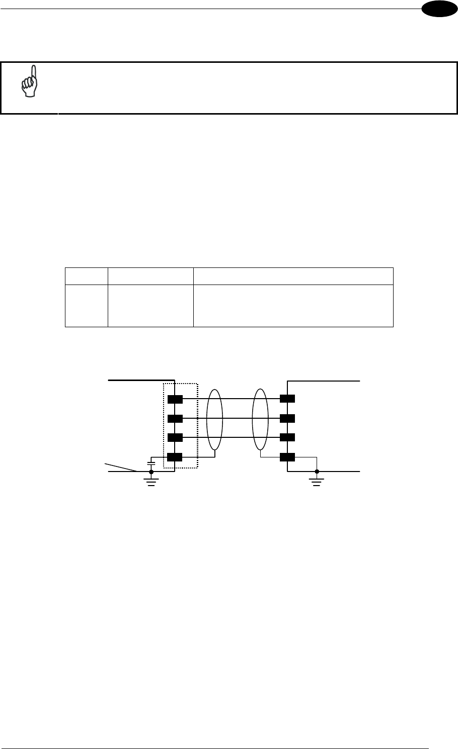
19-PIN CONNECTOR ELECTRICAL CONNECTIONS
67
5
5.4.3 RS485 Half-Duplex Interface
NOTE
This interface is provided for backward compatibility. We recommend using
the more efficient ID-NET™ network for Master/Slave or Multiplexer layouts.
The RS485 half-duplex (3 wires + shield) interface is available for polled communication
protocols.
It can be used for Multidrop connections with a Datalogic Multiplexer, (see par. 6.5) exploiting
a proprietary protocol based on polled mode called MUX32 protocol, where a master device
polls slave devices to collect data.
The following pins of the M16 19-pin connector are used for RS485 half-duplex
communication:
Pin Name Function
M RTX+ RS485 Receive/Transmit Data (+)
N RTX- RS485 Receive/Transmit Data (-)
L GND Ground
MATRI
X
RTX-
RTX+
MULITPLEXER
RTX485-
RTX485+
GND RS485REF
SHIELD
N
M
L
K
Earth Ground Earth Ground
Chassis
Figure 80 - RS485 Half-duplex Connections
This interface is forced by software when the protocol selected is MUX32 protocol.
In a Multiplexer layout, the Multidrop address must also be set via serial channel by the
VisiSet™ utility or by the Host Programming Mode.
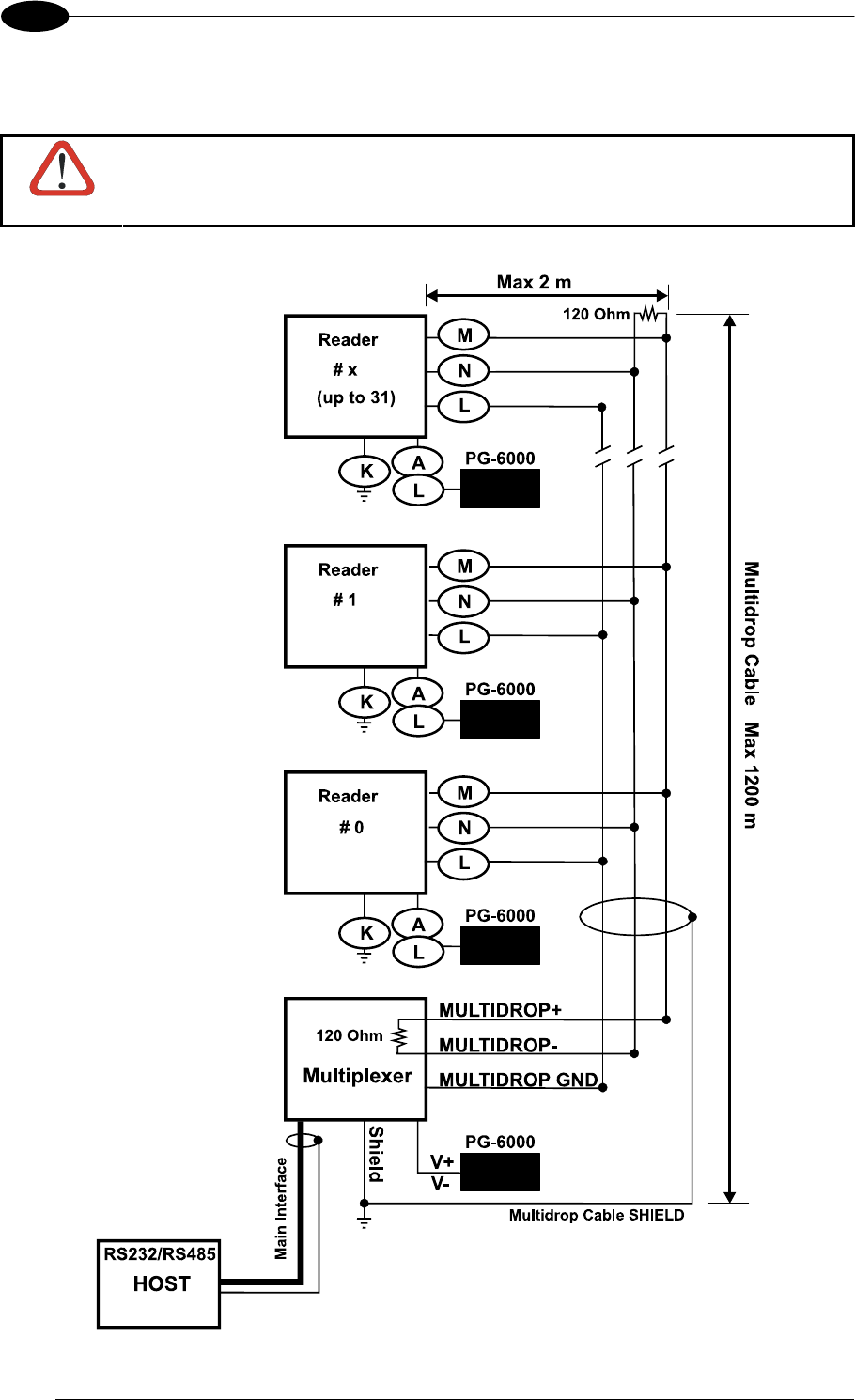
MATRIX 400™ REFERENCE MANUAL
68
5
The figure below shows a multidrop configuration with Matrix 400™ readers connected to a
Multiplexer.
CAUTION
This is an example of multidrop wiring. Consult the multiplexer manual for
complete wiring instructions.
Figure 81 - Matrix 400™ Multidrop Connection to a Mutiplexer

19-PIN CONNECTOR ELECTRICAL CONNECTIONS
69
5
5.5 ID-NET™ INTERFACE
Pin Name Function
R ID+ ID-NET™ network +
P ID- ID-NET™ network -
L GND Ground
5.5.1 ID-NET™ Cables
The following instructions are referred to Figure 83, Figure 84 and Figure 85.
The general cable type specifications are: CAT5 twisted pair + additional CAT5 twisted
pair, shielded cable AWG 24 (or AWG 22) stranded flexible.
We recommend using DeviceNet cables (drop or trunk type) to the following reference
standards:
AN50325 – IEC 62026
UL STYLE 2502 80°C 30V
Cable Shield MUST be connected to earth ground ONLY at the Master.
NEVER use ID-NET™ cable shield as common reference.
The ID-NET™ max cable length depends on the baudrate used, (see the Baudrate Table
below).
For Common Power Connections use only 2 wires (R and P).
- DC Voltage Power cable (Vdc – GND) should be handled as a signal cable (i.e. do
not put it together with AC cable):
- Wire dimensioning must be checked in order to avoid voltage drops greater than 0.8
Volts.
- Cable should lie down as near as possible to the ID-NET™ cable (avoiding wide
loops between them).
Reader's chassis may be connected to earth.
Network inside the same building.
Baudrate Table
Baud Rate 125 kbps 250 kbps 500 kbps 1Mbps
Cable Length 1200 m 900 m 700 m *
* Application dependent, contact your Datalogic Automation representative for details.
NOTE
The default ID-NET™ baudrate is 500 kbps. Lower ID-NET™ baudrates
allow longer cable lengths. The baudrate is software configurable by
authorized Datalogic Automation personnel only.
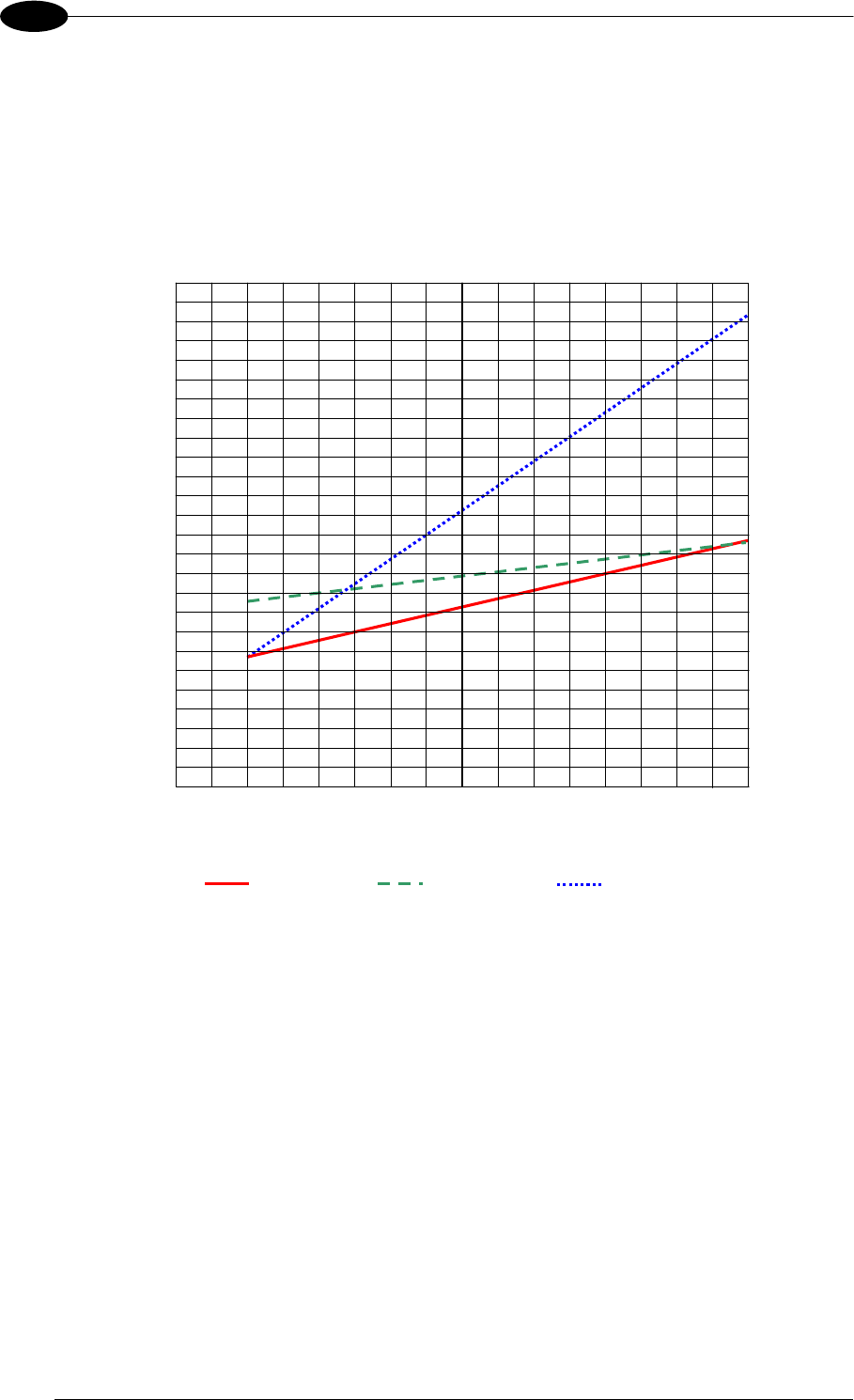
MATRIX 400™ REFERENCE MANUAL
70
5
5.5.2 ID-NET™ Response Time
The following figure shows the response time of the ID-NET™ network. This time is defined
as the period between the Trigger activation and the beginning of data transmission to the
Host.
Max ID-NET™ Response Time
240
220
200
180
160
140
120
100
80
60
40
20
0
Response Time (ms)
Number of Nodes
500 kbps 250 kbps 125 kbps
0 1 2 3 4 5 6 7 8 9 10 11 12 13 14 15 16
Figure 82 – ID-NET™ Response Time
CONDITIONS:
ID-NET™ M/S Synchronized layout
message length = 50 bytes per node
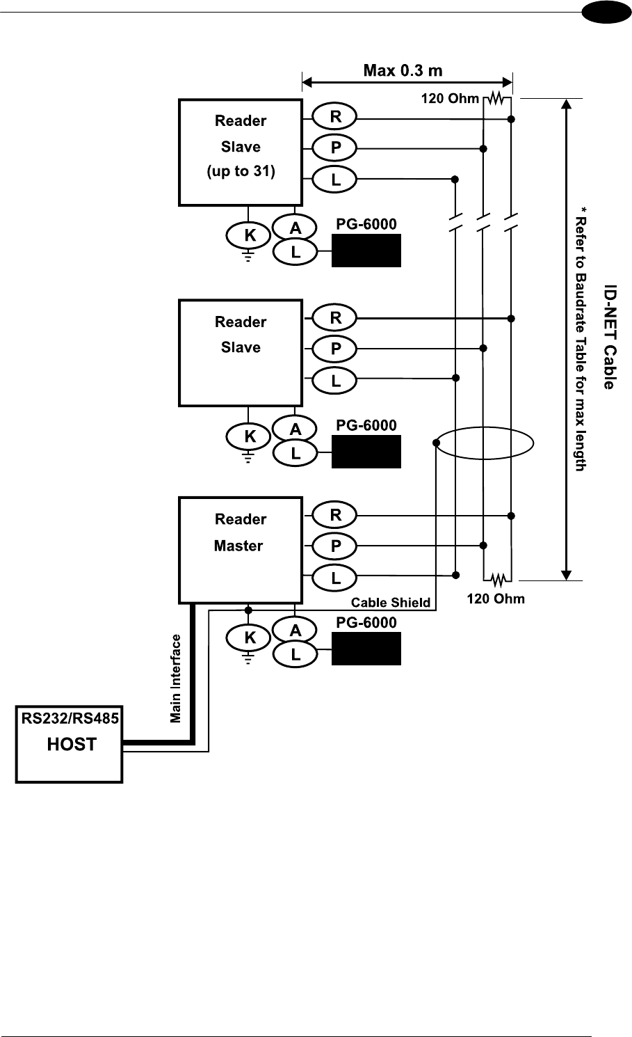
19-PIN CONNECTOR ELECTRICAL CONNECTIONS
71
5
Figure 83 – ID-NET™ Network Connections with isolated power blocks
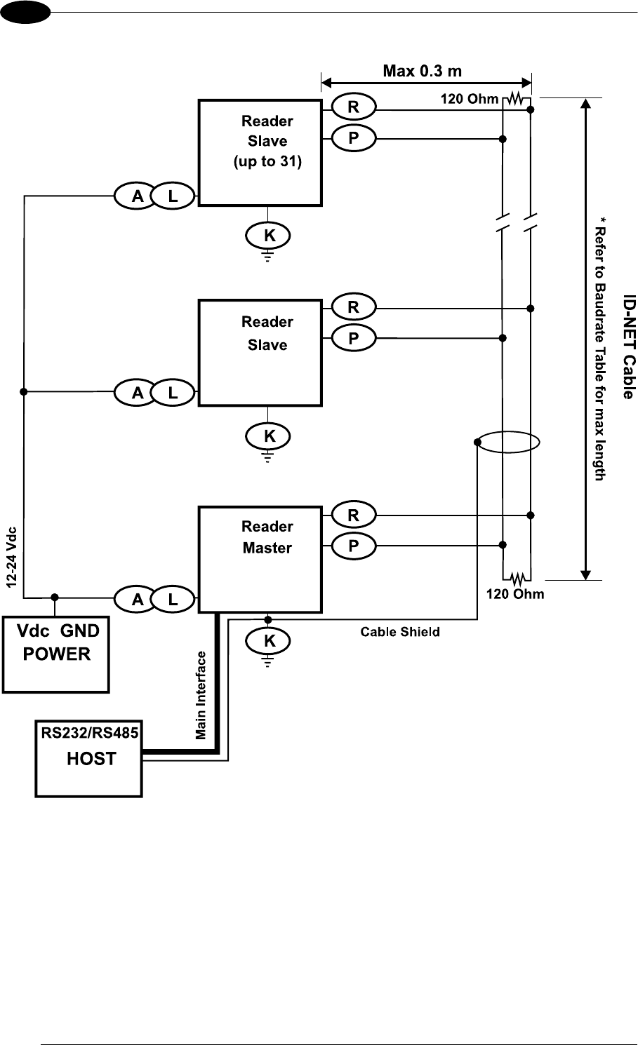
MATRIX 400™ REFERENCE MANUAL
72
5
Figure 84 - ID-NET™ Network Connections with Common Power Branch Network
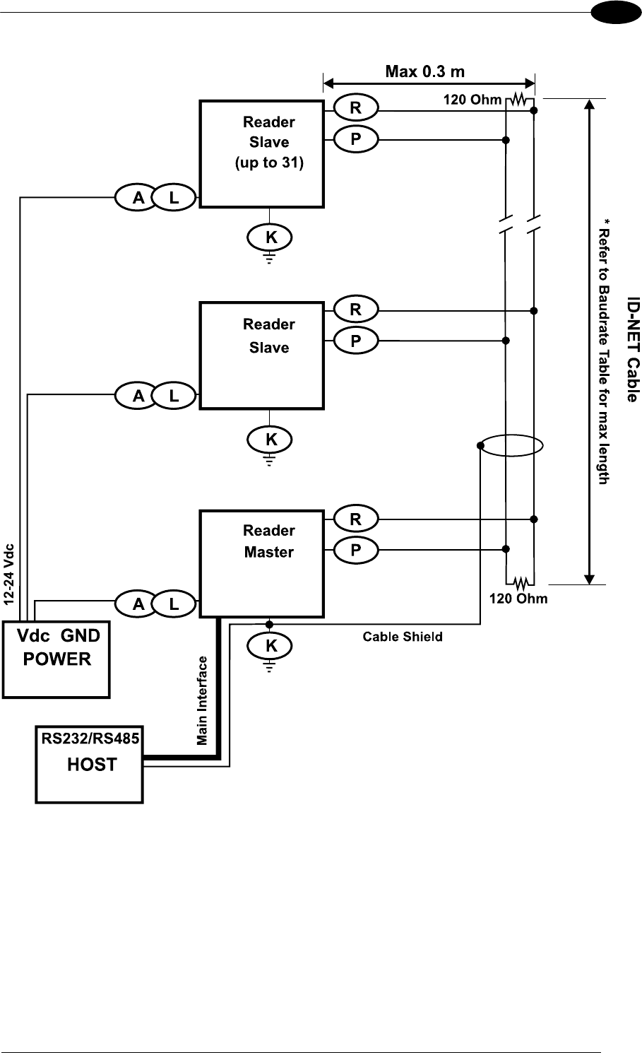
19-PIN CONNECTOR ELECTRICAL CONNECTIONS
73
5
Figure 85 – ID-NET™ Network Connections with Common Power Star Network
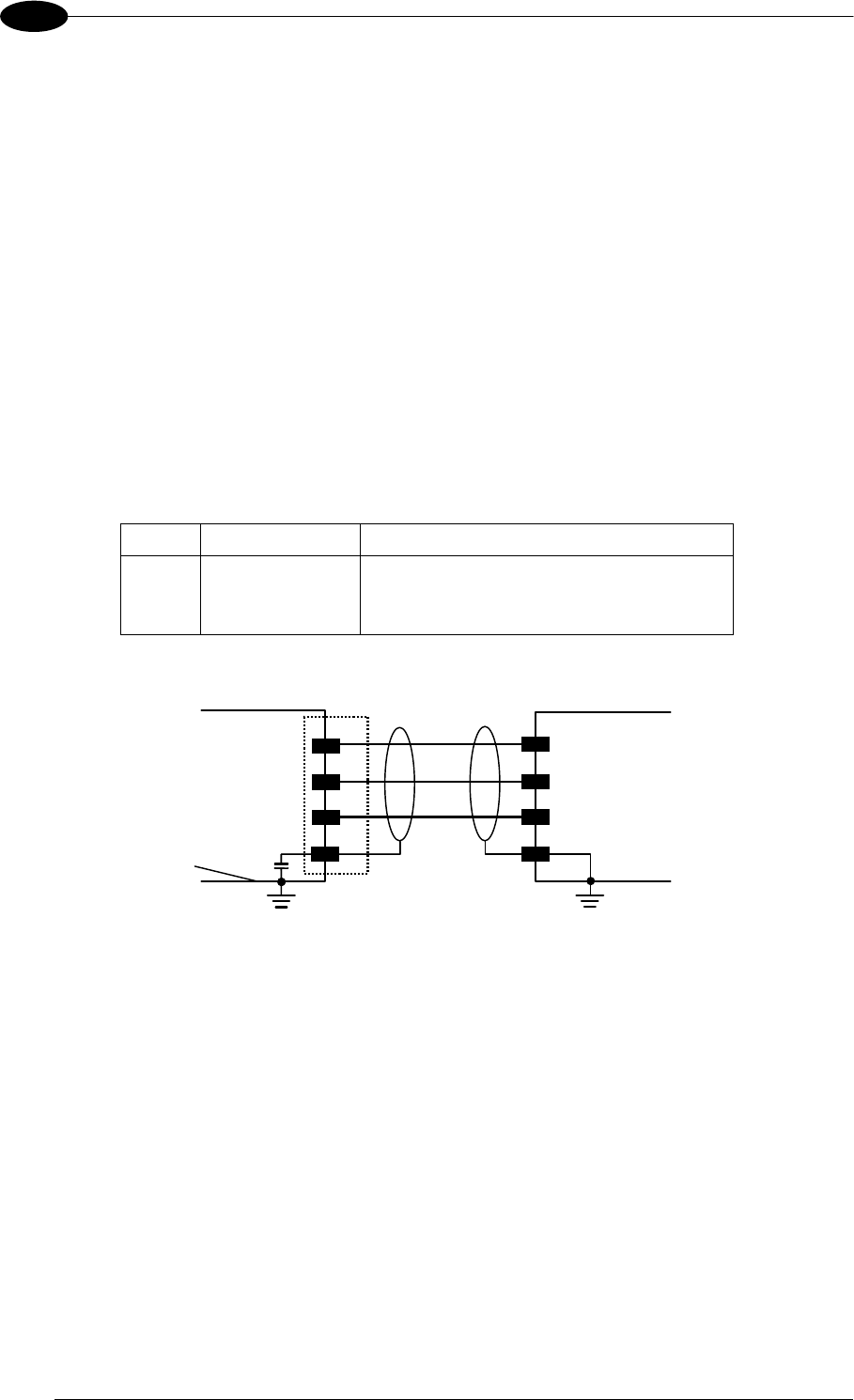
MATRIX 400™ REFERENCE MANUAL
74
5
5.5.3 ID-NET™ Network Termination
The network must be properly terminated by a 120 Ohm resistor at the first and last reader of
the network.
5.6 AUXILIARY RS232 INTERFACE
The RS232 auxiliary interface is available for Point-to-Point, Pass Through or Master/Slave
connections. When it is connected to the host computer it allows both transmission of code
data and reader configuration by VisiSet™.
The parameters relative to the aux interface (baud rate, data bits, etc.) as well as particular
communication modes such as LOCAL ECHO can be defined through the Communication
folder of the VisiSet™ utility program.
The following pins of the M16 19-pin connector are used for auxiliary interface
communication:
Pin Name Function
O TX Transmitted data
S RX Received data
L GND Ground
MATRI
X
TX
RX
USER INTERFACE
RXD
TXD
GND Ground
SHIELD
O
S
L
K
Earth Ground Earth Ground
Chassis
Figure 86 - RS232 Auxiliary Interface Connections Using 19-pin Connector
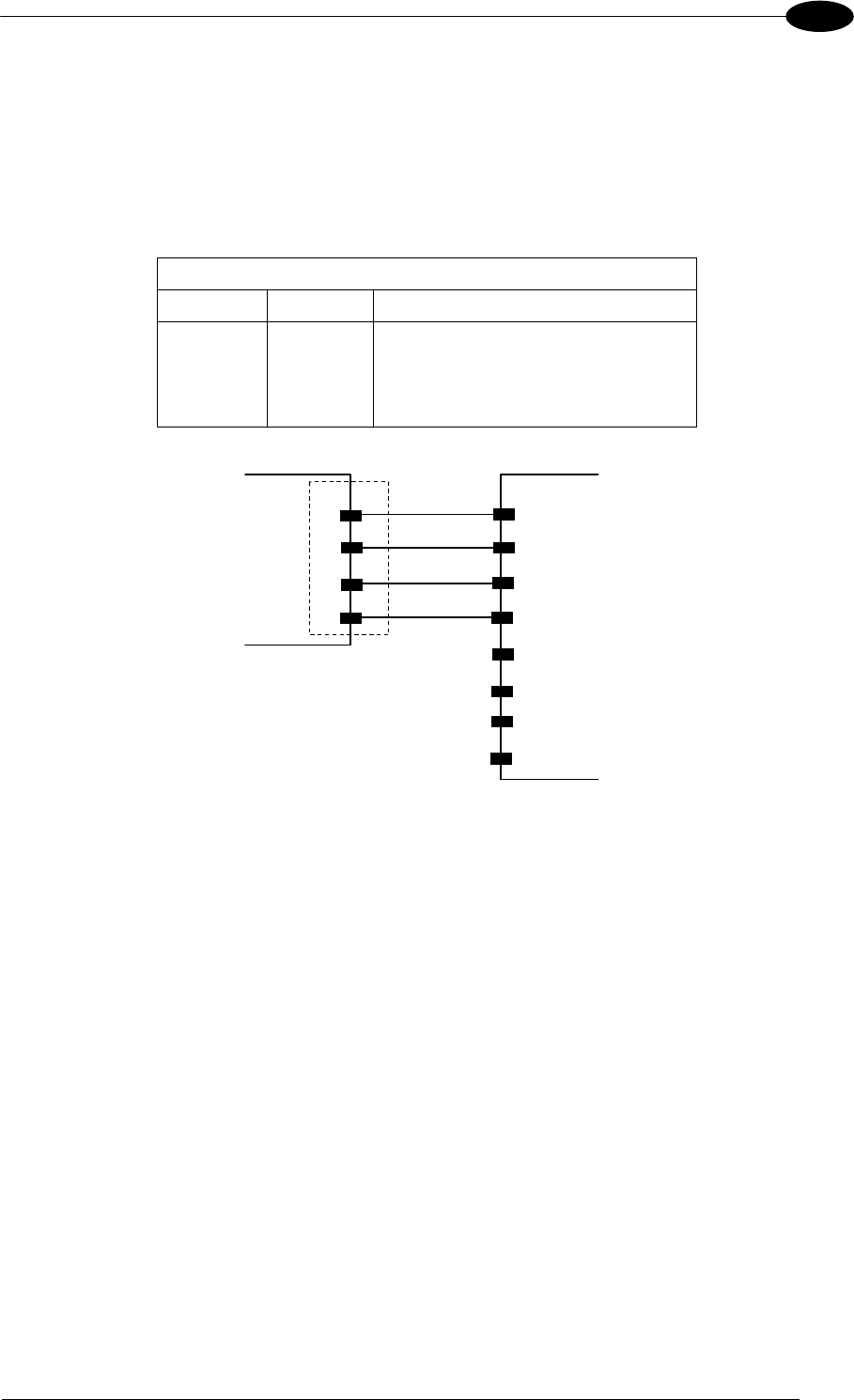
19-PIN CONNECTOR ELECTRICAL CONNECTIONS
75
5
5.7 ETHERNET INTERFACE (MATRIX 400 XXX-010 MODELS ONLY)
The Ethernet Interface can be used for TCP/IP communication with a remote or local host
computer by connecting the reader to either a LAN or directly to a host PC.
The following is an example of a connection to a LAN using a CAB-ETH-M0x straight
through cable:
M12 D-Coded Connector Pinout
Pin Name Function
1 TX+ Transmitted data (positive pin)
2 RX+ Received data (positive pin)
3 TX- Transmitted data (negative pin)
4 RX- Received data (negative pin)
MATRIX
3
4
2
1
TX-
RX+
TX+
RX-
LAN
4
2
6
3
1
5
7
8
TX-
RX+
TX+
RX-
M12
D-coded
RJ45
Figure 87 - Straight-Through Cable
For direct connection to a PC use the CAB-ETH-M0x cable with a crossover adapter.
On the Matrix 400™ Ethernet interface the following communication channels are available:
Data Socket
Image Socket
WebSentinel Socket
Image FTP Client
HTTP Server
Email Client
Ethernet IP
For further details refer to the Ethernet Folder in the VisiSet™ Help On Line and to the
"Matrix Ethernet Service Guide.pdf" document provided as supplementary documentation.
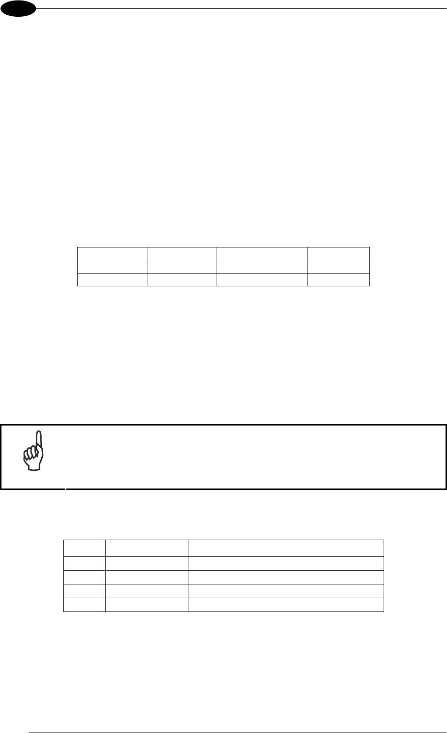
MATRIX 400™ REFERENCE MANUAL
76
5
5.8 INPUTS
There are two optocoupled polarity insensitive inputs available on the M16 19-pin connector
of the reader: Input 1 (External Trigger) and Input 2, a generic input:
The External Trigger can be used in One Shot Mode or in Phase Mode. Its main functions
are:
acquisition trigger in One Shot Mode
reading phase-ON/reading phase-OFF command in Phase Mode
The main functions of the general purpose Input 2 are:
second external trigger in Phase Mode
match code storage command when the Match Code option is enabled
The electrical features of both inputs are:
INPUT | V
AB | Min. | V AB | Max. I IN Max.
Open 0 V 2 V 0 mA
Closed 4.5 V 30 V 10 mA
The active state of these inputs are selected in software. Refer to the VisiSet™ Help On
Line.
An anti-disturbance filter is implemented in software on both inputs so that the minimum
pulse duration is 0.5 milliseconds. This value can be increased through the software
parameter Debounce Filter, see the Digital I/O folder in the VisiSet™ Help On Line for further
details.
These inputs are optocoupled and can be driven by both NPN and PNP type commands.
NOTE
Polarity insensitive inputs assure full functionality even if pins A and B are
exchanged.
The connections are indicated in the following diagrams:
Pin Name Function
A Vdc Power Supply input voltage +
B I1A External Trigger A (polarity insensitive)
C I1B External Trigger B (polarity insensitive)
L GND Power Supply input voltage -
The yellow Trigger LED (Figure 19, 5) is on when the active state of the External Trigger
corresponds to ON.
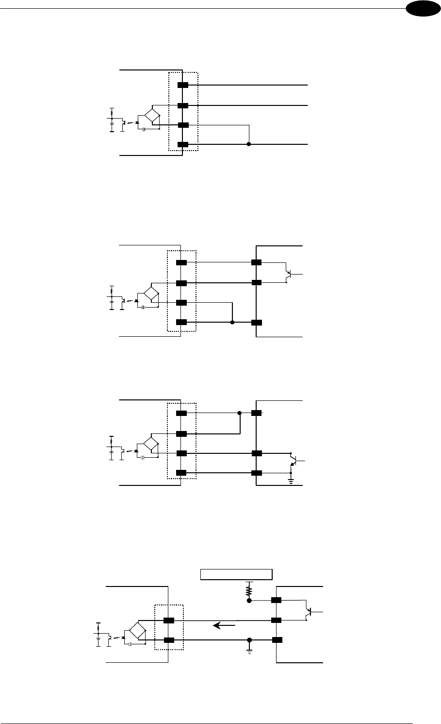
19-PIN CONNECTOR ELECTRICAL CONNECTIONS
77
5
EXTERNAL TRIGGER INPUT PNP PH-1
Vdc
GND
I1A
I1B
PNP PH-1 wires
Matrix 400™
B
C
L
(brown) +10-30 Vdc
(black) NO
(blue) 0 V
VCC ~
~
+-
A
Figure 88 - External Trigger Using PNP PH-1 Photocell
EXTERNAL TRIGGER INPUT CONNECTIONS USING MATRIX 400™ POWER
EXTERNAL TRIGGER
Matrix 400™
B
C
A
LGround
V
Signal
VCC ~
~
+-
Vdc
GND
I1A
I1B
Figure 89 – External Trigger PNP Using Matrix 400™ Power
EXTERNAL TRIGGER
Matrix 400™
Signal
B
C
A
LGround
V
VCC ~
~
+-
Vdc
GND
I1A
I1B
Figure 90 - External Trigger NPN Using Matrix 400™ Power
EXTERNAL TRIGGER INPUT CONNECTIONS USING EXTERNAL POWER
Matrix 400™ EXTERNAL TRIGGER
Vext 30 Vdc max.
A
B
VCC ~
~
+ -
V
Signal
I1A
I1B I in
Figure 91 - External Trigger PNP Using External Power
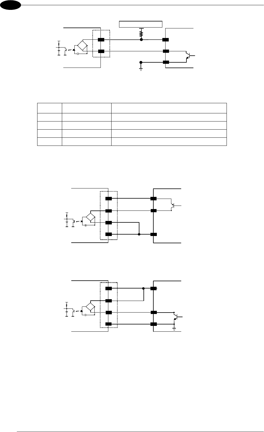
MATRIX 400™ REFERENCE MANUAL
78
5
Matrix 400™ EXTERNAL TRIGGER
Vext 30 Vdc max.
A
B
Signal
V
VCC ~
~
+ -
I1A
I1B
Figure 92 - External Trigger NPN Using External Power
Pin Name Function
A Vdc Power Supply input voltage +
D I2A Input 2 A (polarity insensitive)
E I2B Input 2 B (polarity insensitive)
L GND Power Supply input voltage -
INPUT 2 CONNECTIONS USING MATRIX 400™ POWER
INPUT DEVICE
Matrix 400™
D
E
A
LGround
V
Signal
VCC ~
~
+-
Vdc
GND
I2A
I2B
Figure 93 - Input PNP Using Matrix 400™ Power
INPUT DEVICE
Matrix 400™
Signal
D
E
A
LGround
V
VCC ~
~
+-
Vdc
GND
I2A
I2B
Figure 94 - Input NPN Using Matrix 400™ Power
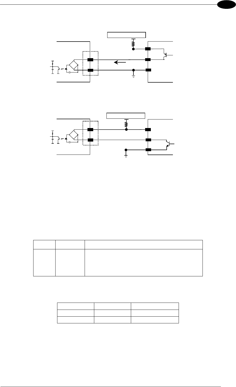
19-PIN CONNECTOR ELECTRICAL CONNECTIONS
79
5
INPUT 2 CONNECTIONS USING EXTERNAL POWER
Matrix 400™ INPUT DEVICE
Vext 30 Vdc max.
D
E
VCC ~
~
+ -
V
Signal
I2A
I2B I in
Figure 95 - Input PNP Using External Power
Matrix 400™ INPUT DEVICE
Vext 30 Vdc max.
D
E
Signal
V
VCC ~
~
+ -
I2A
I2B
Figure 96 - Input NPN Using External Power
5.9 OUTPUTS
Two opto-coupled general purpose outputs are available on the M16 19-pin connector. The
meaning of the two outputs Output 1 and Output 2 can be defined by the user. They are
typically used either to signal the data collection result or to control an external lighting
system.
The pinout is the following:
Pin Name Function
H O1+ Configurable digital output 1 - positive pin
F O1- Configurable digital output 1 - negative pin
G O2+ Configurable digital output 2 - positive pin
I O2- Configurable digital output 2 - negative pin
The electrical features of the two outputs are the following:
OUTPUT ILoad V
Out
Open 0 mA 30 Vdc Max
Closed 10 mA 1.8 Vdc Max
PD = VOut IoLoad = 170 mW Max.
By default, Output 1 is associated with the Partial Read and No Read events, which activates
when the code(s) signaled by the external trigger are not decoded, and Output 2 is
associated with the Complete Read event, which activates when all the selected codes are
correctly decoded.
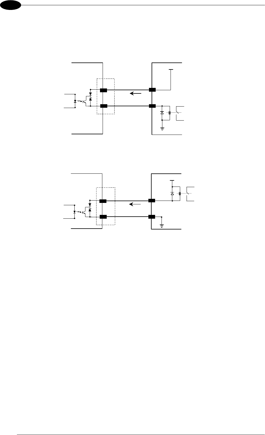
MATRIX 400™ REFERENCE MANUAL
80
5
The output signals are fully programmable being determined by the configured
Activation/Deactivation events, Deactivation Timeout or a combination of the two. Refer to
the Digital I/O folder in the VisiSet™ Help On Line for further details.
MATRIX USER INTERFACE
Vext 30 Vdc max
H/G
F/I
I Load
V Out
Figure 97 - Open Emitter Output Connection
MATRIX USER INTERFACE
Vext 30 Vdc max
H/G
F/I I Load
V Out
Figure 98 - Open Collector Output Connection
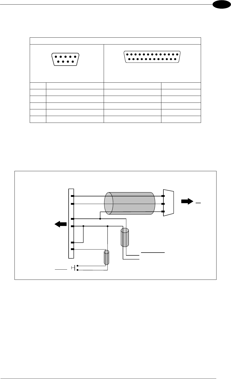
19-PIN CONNECTOR ELECTRICAL CONNECTIONS
81
5
5.10 USER INTERFACE
RS232 PC-side connections
15
9 6
9-pin male connector
13
2514
1
25-pin male connector
Pin Name Pin Name
2 RX 3 RX
3 TX 2 TX
5 GND 7 GND
7 RTS 4 RTS
8 CTS 5 CTS
How To Build A Simple Interface Test Cable:
The following wiring diagram shows a simple test cable including power, external (push-
button) trigger and PC RS232 COM port connections.
M16 19-pin female
S RX
TX
O
Matrix 400™ A
L
Vdc
GND
9-pin D-sub female
GND
TX
RX
PC
2
3
5
B I1A
Power Supply
Power GND
VS (10 – 30 VDC)
Trigger
I1B
C
Figure 99- Test Cable for Matrix 400™
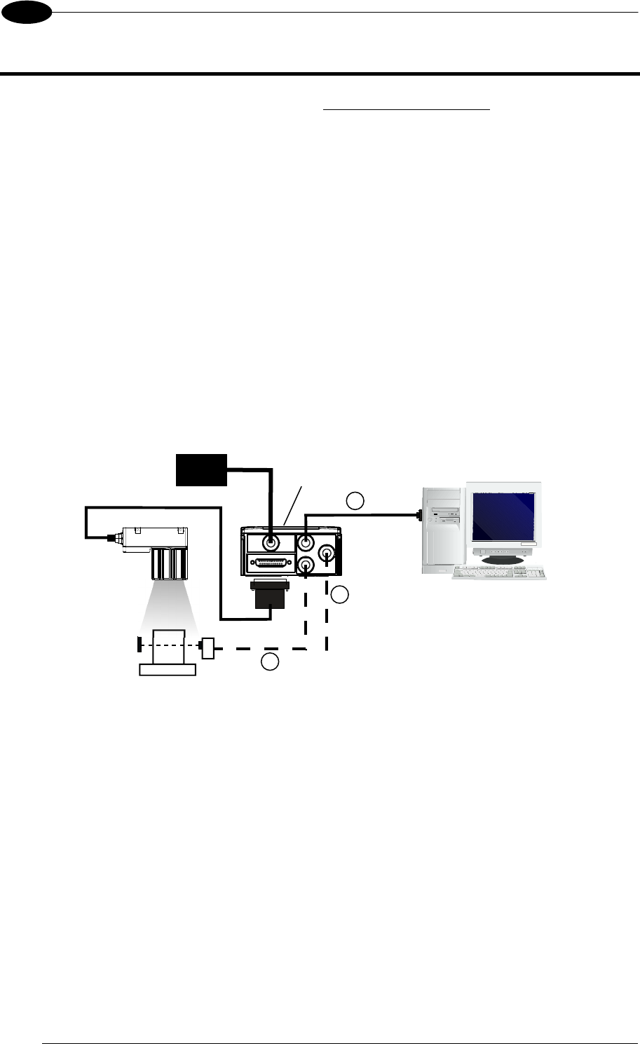
MATRIX 400™ REFERENCE MANUAL
82
6
6 TYPICAL LAYOUTS
The following typical layouts refer to system hardware configurations. However, they also
require the correct setup of the software configuration parameters. Dotted lines in the figures
refer to optional hardware configurations within the particular layout.
6.1 POINT-TO-POINT
In this layout the data is transmitted to the Host on the main serial interface. The RS232
auxiliary interface can be used for reader configuration by connecting a laptop computer
running VisiSet™. Host Mode programming can be accomplished either through the main
interface or the Auxiliary interface.
In Local Echo communication mode, data is transmitted on the RS232 auxiliary interface
independently from the main interface selection.
When One Shot or Phase Mode operating mode is used, the reader can be activated by an
External Trigger (for example a pulse from a photoelectric sensor) when the object enters its
reading zone.
Figure 100 – Serial Interface Point-to-Point Layout
Terminal
Matrix 400™
1
2
3
Main Serial Interface (RS232 or RS485 Full-Duplex)
Auxiliary Serial Interface (Local Echo) (RS232)
External Trigger (for One Shot or Phase Mode)
Host
PG6000 CBX
CAB-MSxx
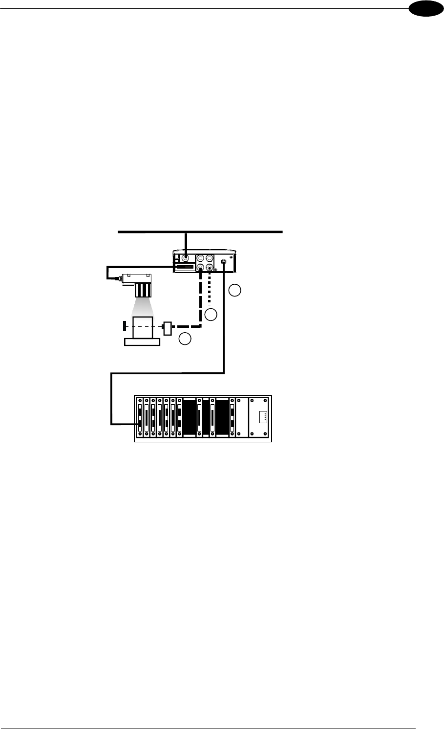
TYPICAL LAYOUTS
83
6
In this layout a single reader functions as a Slave node on a Fieldbus network. The data is
transmitted to the Host through an accessory Fieldbus interface board installed inside the
CBX500 connection box.
Reader configuration can be accomplished through the Auxiliary interface using the VisiSet™
configuration program or Host Mode programming.
In Local Echo communication mode, data is transmitted on the RS232 auxiliary interface
independently from the Fieldbus interface selection.
When One Shot or Phase Mode operating mode is used, the reader can be activated by an
External Trigger (photoelectric sensor) when the object enters its reading zone.
Figure 101 – Fieldbus Interface Point-to-Point Layout
Matrix 400™ 1
2
3
Fieldbus Interface (Profibus, DeviceNet, etc.)
Auxiliary Serial Interface (Local Echo) (RS232)
External Trigger (for One Shot or Phase Mode)
Host
Power
CBX500
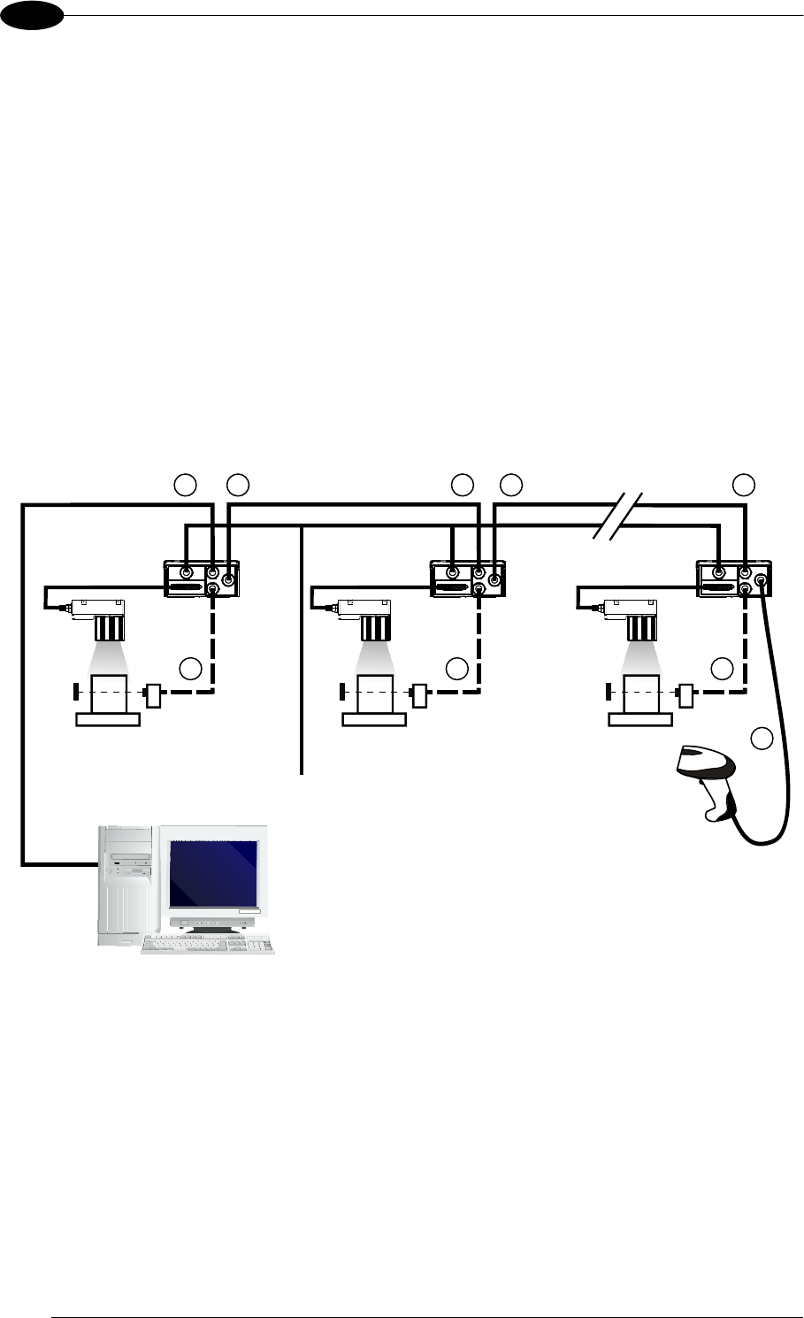
MATRIX 400™ REFERENCE MANUAL
84
6
6.2 PASS-THROUGH
Pass-through mode allows two or more devices to be connected to a single external serial
interface.
Each reader transmits the messages received by the Auxiliary interface onto the Main
interface. All messages will be passed through this chain to the host.
When One Shot or Phase Mode operating mode is used, the reader can be activated by an
External Trigger (for example a pulse from a photoelectric sensor) when the object enters its
reading zone.
Applications can be implemented to connect a device such as a hand-held reader to the
Auxiliary port of the last reader in the chain for manual code reading capability.
The Main and Auxiliary ports are connected as shown in the figure below:
Figure 102 – Pass-Through Layout
Host
12
3 3
1
Device#1
3
Main Serial Interface (RS232 only)
Auxiliary Serial Interface (RS232)
External Trigger (for One Shot or Phase Mode)
2 1
Device#2 Device#n
2
Power
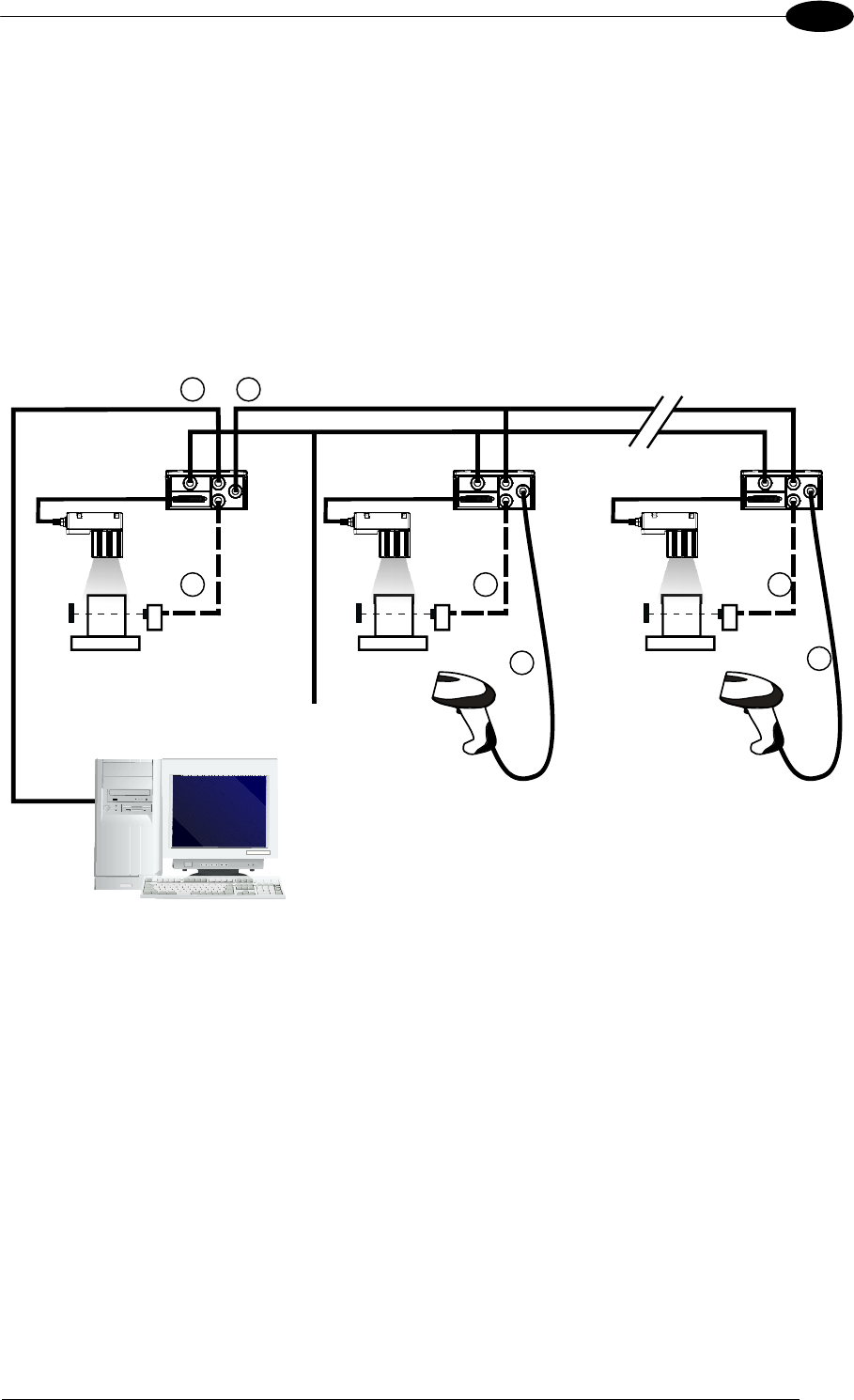
TYPICAL LAYOUTS
85
6
An alternative Pass-Through layout allows the more efficient ID-NET™ network to be used.
This layout is really an ID-NET Master/Slave Multidata layout which also allows each reader
(Master and Slaves) to accept input on the Auxiliary interface, for example to connect a
device such as a hand-held reader for manual code reading capability.
Each Matrix 400™ transmits its own messages plus any messages received by its Auxiliary
interface onto the ID-NET™ interface. The Master passes all messages to the Host.
When One Shot or Phase Mode operating mode is used, the reader can be activated by an
External Trigger (photoelectric sensor) when the object enters its reading zone.
Figure 103 – Pass-Through On ID-NET™ Layout
Host
14
3 3
Master
3
Main Serial Interface (RS232 or RS485)
Auxiliary Serial Interface (RS232)
External Trigger (for One Shot or Phase Mode)
ID-NET™
Slave#2 Slave#n
2
Power 2
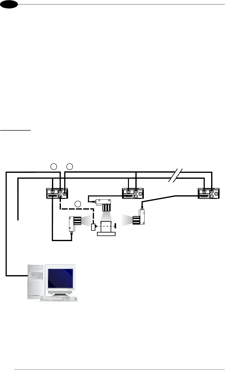
MATRIX 400™ REFERENCE MANUAL
86
6
6.3 ID-NET™
The ID-NET™ connection is used to collect data from several readers to build a multi-point or
a multi-sided reading system; there can be one master and up to 31 slaves connected
together.
The slave readers are connected together using the ID-NET™ interface. Every slave reader
must have an ID-NET™ address in the range 1-31.
The master reader is also connected to the Host on the RS232/RS485 main serial interface.
For a Master/Slave Synchronized layout the External Trigger signal is unique to the system;
there is a single reading phase and a single message from the master reader to the Host
computer. It is not necessary to bring the External Trigger signal to all the readers.
In the Master/Slave Synchronized layout the Master operating mode can only be set to
Phase Mode.
The main, auxiliary, and ID-NET™ interfaces are connected as shown in the figure below.
Figure 104 – ID-NET™ M/S Synchronized Layout
Main Serial Interface (RS232 or RS485)
External Trigger
ID-NET™ (up to 16 devices - practical limit)
Host
13
2
Master
Slave#1 Slave#n
Power
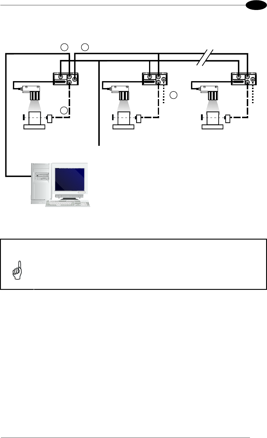
TYPICAL LAYOUTS
87
6
For a Master/Slave Multidata layout each reader has its own reading phase independent
from the others; each single message is sent from the master reader to the Host computer.
Figure 105 – ID-NET™ M/S Multidata
NOTE
The auxiliary serial interface of the slave readers can be used in Local Echo
communication mode to control any single reader (visualize collected data)
or to configure it using the VisiSet™ utility.
The ID-NET™ termination resistor switches must be set to ON only in the first
and last CBX connection box.
Terminal
Main Serial Interface (RS232 or RS485)
Auxiliary Serial Interface (Local Echo) (RS232)
External Trigger (for One Shot or Phase Mode)
ID-NET™ (up to 32 devices, max network extension of 1000 m)
Host
14
3
2
Master Slave#1 Slave#n
Power
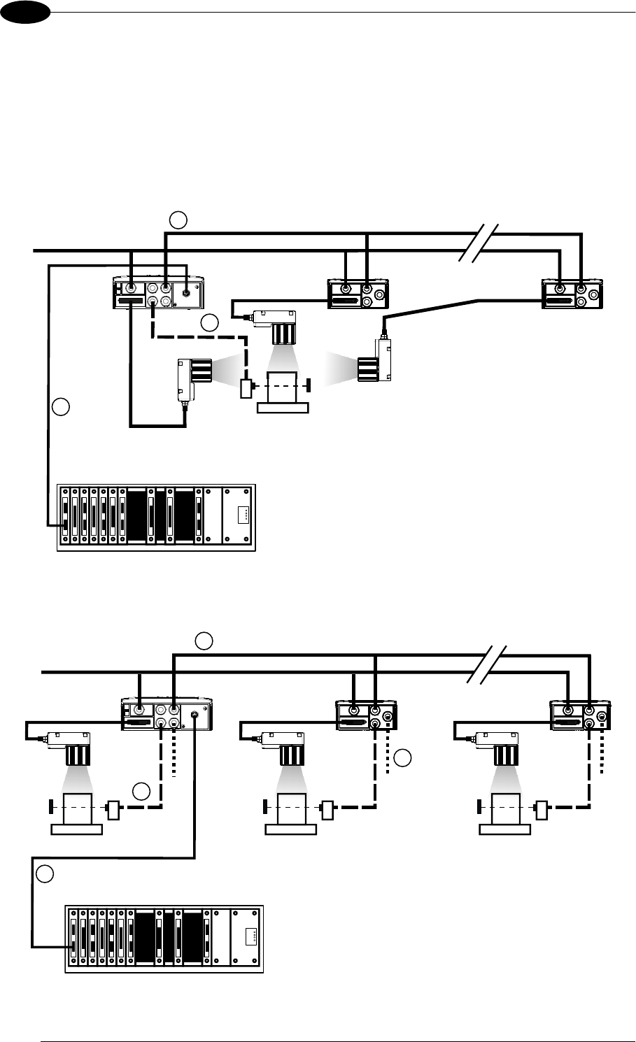
MATRIX 400™ REFERENCE MANUAL
88
6
Alternatively, the Master reader can communicate to the Host as a Slave node on a Fieldbus
network. This requires using an accessory Fieldbus interface board installed inside the
CBX500 connection box.
System configuration can be accomplished through the Auxiliary interface of each individual
reader (internal CBX500 9-pin connector) using the VisiSet™ configuration program or Host
Mode programming. See par. 2.3.1 for details.
Figure 106 – ID-NET™ Fieldbus M/S Synchronized Layout
Figure 107 – ID-NET™ Fieldbus M/S Multidata
Fieldbus Interface
External Trigger (for One Shot or Phase Mode)
ID-NET™ (up to 16 devices - practical limit)
Host
2
Maste
r
Slave#1 Slave#n
Power
1
3
Terminal
Fieldbus Interface
Auxiliary Serial Interface (Local Echo) (RS232)
External Trigger (for One Shot or Phase Mode)
ID-NET™ (up to 32 devices, max network extension of 1000 m)
Host
1
4
3
2
Master Slave#1 Slave#n
Power
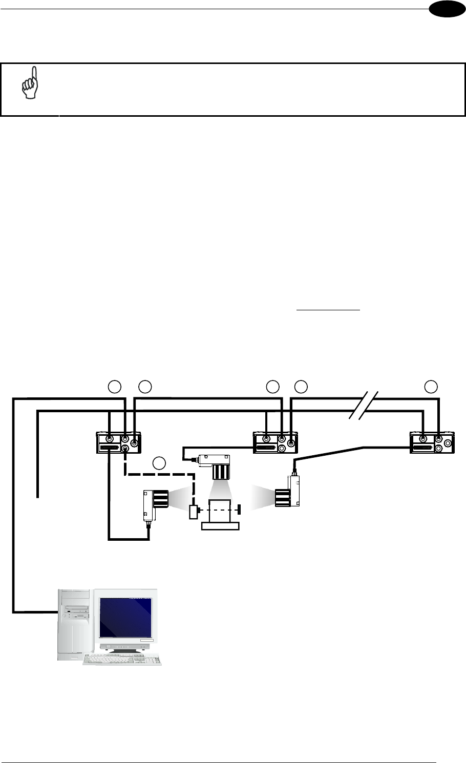
TYPICAL LAYOUTS
89
6
6.4 RS232 MASTER/SLAVE
NOTE
This interface is provided for backward compatibility. We recommend using
the more efficient ID-NET™ network for Master/Slave or Multiplexer layouts.
The RS232 master/slave connection is used to collect data from several readers to build either
a multi-point or a multi-sided reading system; there can be one master and up to 9 slaves
connected together.
The Slave readers use RS232 only on the main and auxiliary serial interfaces. Each slave
reader transmits the messages received by the auxiliary interface onto the main interface. All
messages will be passed through this chain to the Master.
The Master reader is connected to the Host on the RS232/RS485 main serial interface.
There is a single reading phase and a single message from the master reader to the Host
computer.
In this layout the Master operating mode can be set only to Phase Mode.
The Phase ON/OFF signals must be brought only to the Master. It is not necessary to
bring them to the Slave readers.
The main and auxiliary ports are connected as shown in the figure below.
Figure 108 – RS232 Master/Slave Layout
Host
12
3
1
Master
Main Serial Interface (Slaves RS232 only)
Auxiliary Serial Interface (RS232)
External Trigger
2 1
Slave#1 Slave#n
Power
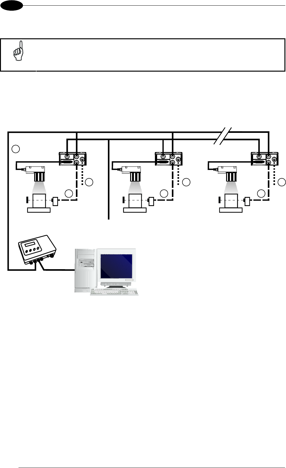
MATRIX 400™ REFERENCE MANUAL
90
6
6.5 MULTIPLEXER
NOTE
This interface is provided for backward compatibility. We recommend using
the more efficient ID-NET™ network for Master/Slave or Multiplexer layouts.
Each reader is connected to a Multiplexer (for example MX4000) with the RS485 half-duplex
main interface through a CBX connection box.
Before proceeding with the connection it is necessary to select the MUX32 communication
protocol and the multidrop address for each reader.
Figure 109 - Multiplexer Layout
The auxiliary serial interface of the slave readers can be used in Local Echo communication
mode to control any single reader (visualize collected data) or to configure it using the
VisiSet™ utility.
Each reader has its own reading phase independent from the others. When One Shot or
Phase Mode operating mode is used, the reader can be activated by an External Trigger (for
example a pulse from a photoelectric sensor) when the object enters its reading zone.
MX4000
Host
0
1
2
3
Main Serial Interface (RS485 Half-Duplex)
Auxiliary Serial Interface (Local Echo) (RS232)
External Trigger (for One Shot or Phase Mode)
1 31
33
2 2
Power
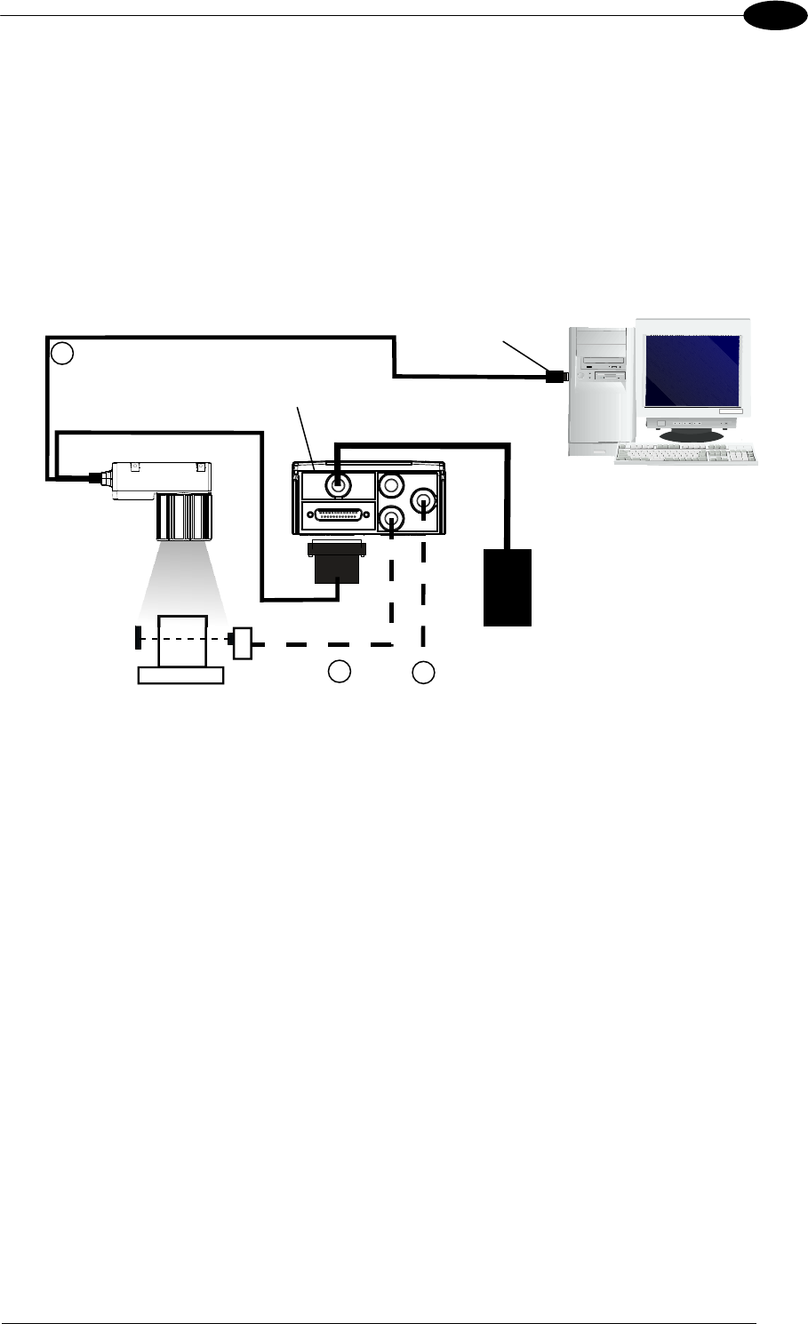
TYPICAL LAYOUTS
91
6
6.6 ETHERNET CONNECTION (MATRIX 400 XXX-010 MODELS ONLY)
For Matrix 400 XXX-010 models, the Ethernet connection is possible in two different layouts.
In both layouts, before proceeding with the connection, it is necessary to configure the reader
Ethernet parameters via VisiSet™. For further details, see the Ethernet Folder in the
VisiSet™ Help On Line.
In a Point-to-Point layout the reader is connected to a local host by using a CAB-ETH-M0x
cable with a crossover adapter.
Figure 110 - Ethernet Point-to-Point Layout
CBX
Host
Matrix 400™
CAB-MS0x
CAB-ETH-M0x
PG 6000
Crossover
A
dapte
r
1
2 Ethernet Interface (with Crossover Adapter)
Auxiliary Serial Interface (Local Echo) (RS232)
External Trigger (for One Shot or Phase Mode)
3
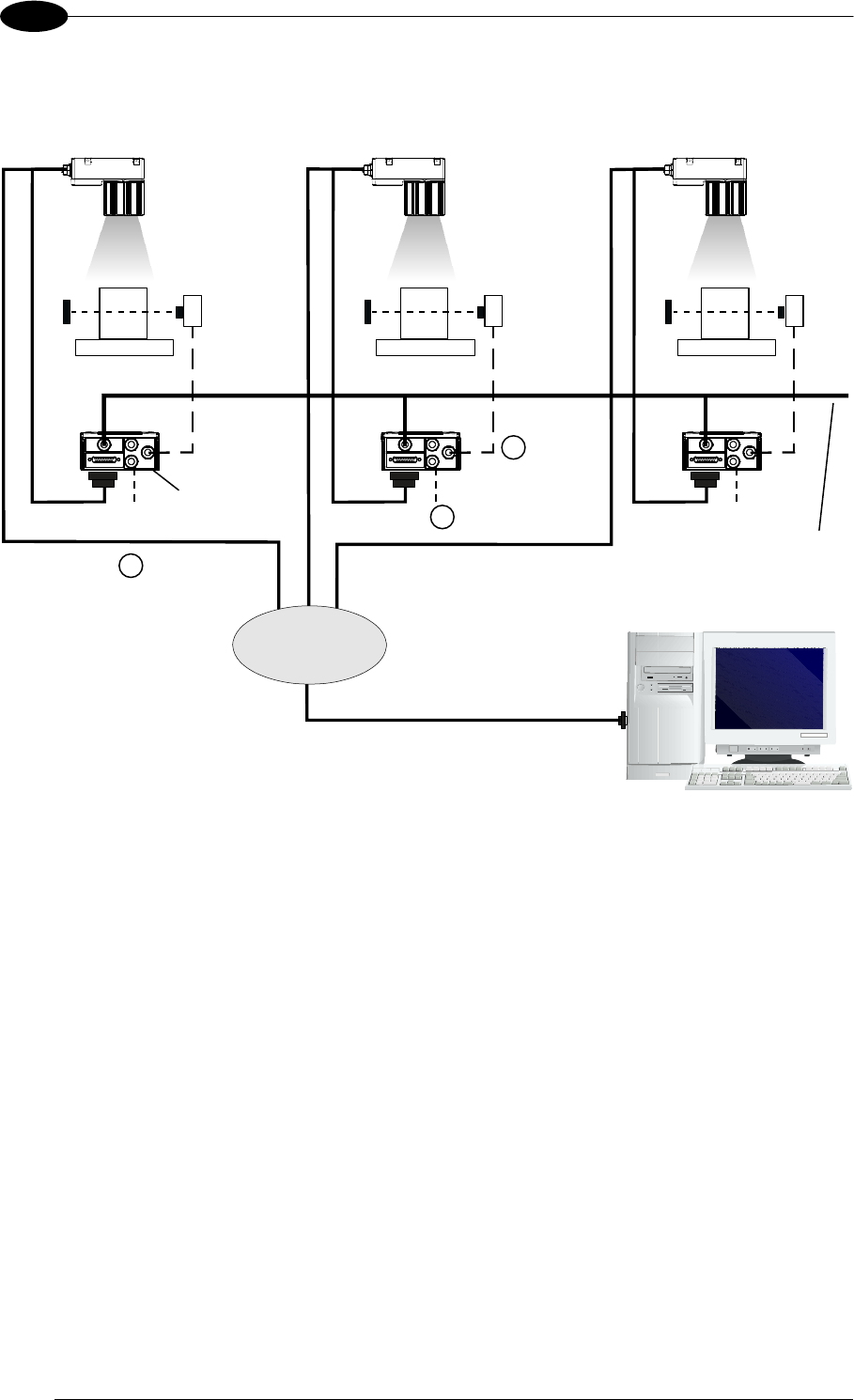
MATRIX 400™ REFERENCE MANUAL
92
6
When using a Local Area Network (LAN), one or more Matrix 400 XXX-010s can be
connected to the network by using CAB-ETH-M0x straight through cables:
Figure 111 - Ethernet Network Layout
CBX
Matrix 400™
HOST
NETWORK
Powe
r
CAB-ETH-M0x
CAB-MSxx
1
2
3
Ethernet Interface (Straight Through Cables)
Auxiliary Serial Interface (Local Echo) (RS232)
External Trigger (for One Shot or Phase Mode)
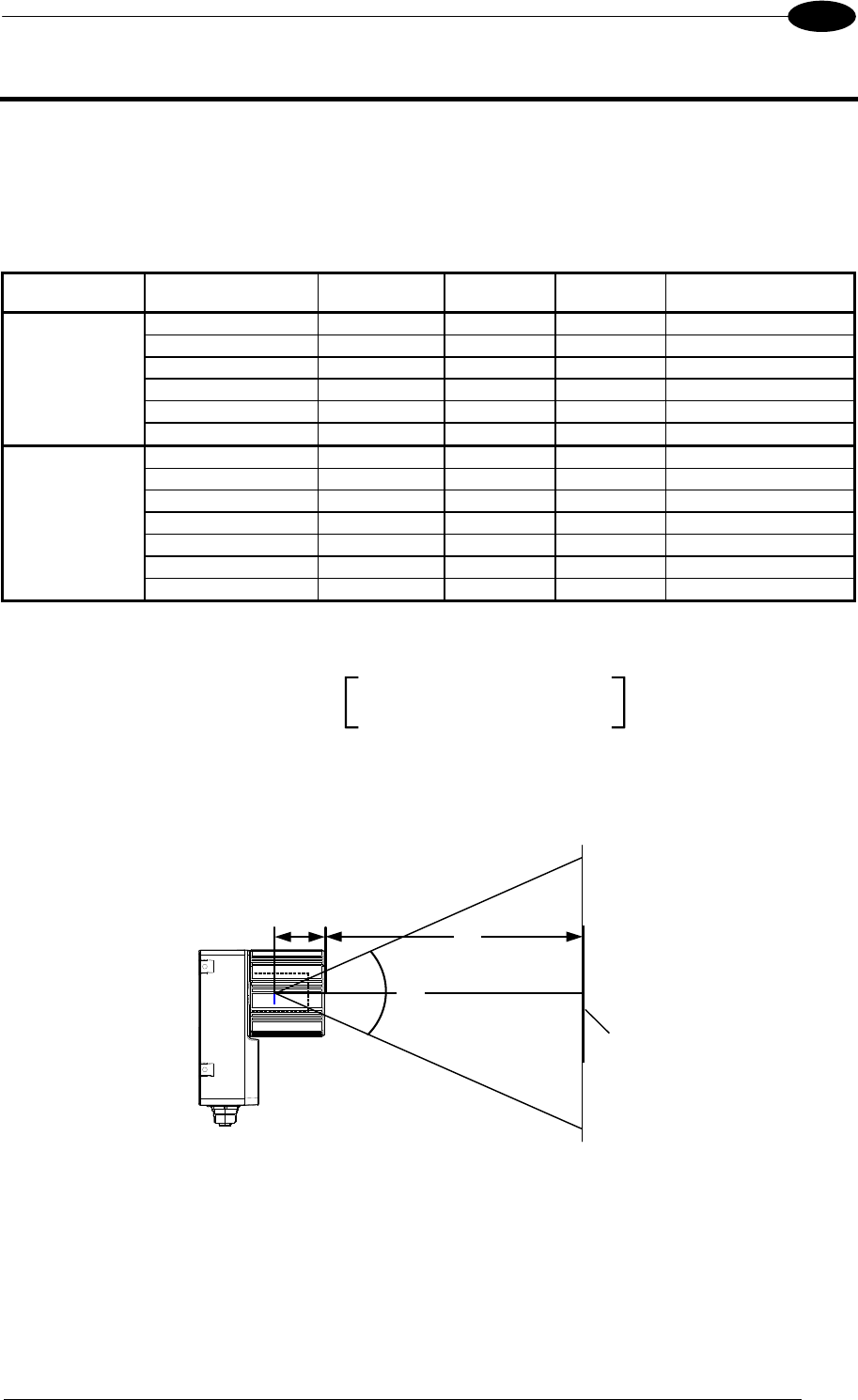
READING FEATURES
93
7
7 READING FEATURES
7.1 OPTICAL ACCESSORY SELECTION
Referring to Figure 112 and the formula below, use the data in the following table to calculate
the FOV for your application.
Model Lens
Viewing Angle
Horizontal
Viewing Angle
Vertical
Viewing Angle
Diagonal
Min Focus Distance
mm
LNS-1109 9 mm 48.5° 39.5° 60° 85
LNS-1112 12.5 mm 37° 30° 46.5° 85
LNS-1116 16 mm 28.5° 23° 36° 85
LNS-1125 25 mm 18.5° 15° 23.5° 135
LNS-1135 35 mm 13° 10,5° 16.5° 235
Matrix 400
400-0x0
(SXGA)
LNS-1150 50 mm 9° 7° 11.5° 500
LNS-1006 6 mm 59.5° 46.5° 71° 85
LNS-1109 9 mm 40.5° 31° 49.5° 85
LNS-1112 12.5 mm 31° 23.5° 38° 85
LNS-1116 16 mm 24° 18° 30° 85
LNS-1125 25 mm 15° 11.5° 19° 135
LNS-1135 35 mm 11° 8.5° 13.5° 235
Matrix 400
600-0x0
(UXGA)
LNS-1150 50 mm 7.5° 5.5° 9.5° 500
The viewing angle has a tolerance of 1° depending on the focus distance.
FOVx = 2 (d + 35 mm) tan (x/2)
where:
FOVx = horizontal, vertical or diagonal FOV
x = horizontal, vertical or diagonal viewing angles.
d = focus distance
d
35 mm
FOV
plane
Figure 112 – Reading Distance References
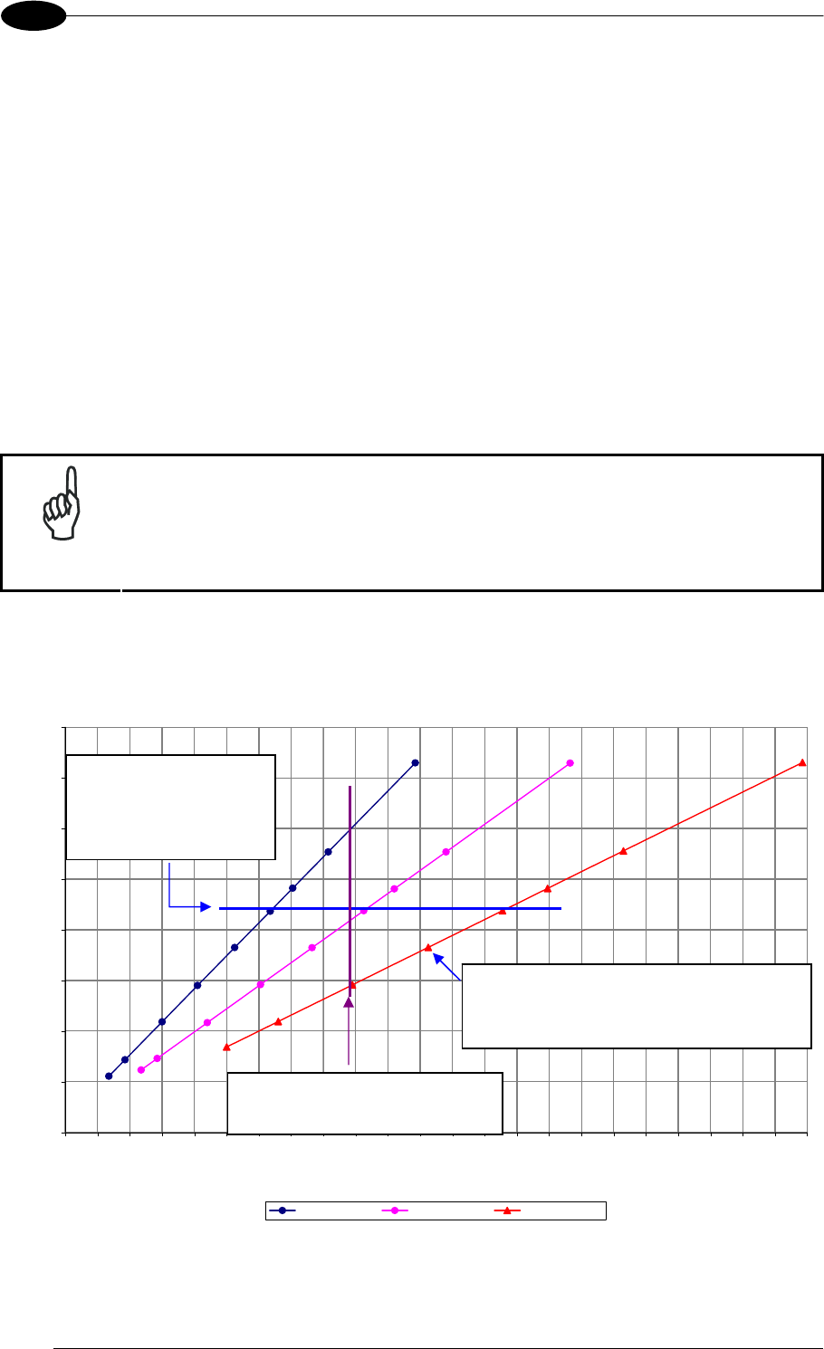
MATRIX 400™ REFERENCE MANUAL
94
7
Example:
The FOV for a Matrix 400 600-0x0 base using the 16 mm lens at a focus distance of 200
mm is:
FOVH = 2 [(200 mm + 35 mm) tan (24°/2)] = 100 mm
FOVV = 2 [(200 mm + 35 mm) tan (18°/2)] = 74 mm
7.2 HORIZONTAL FOV VS. READING DISTANCE DIAGRAMS
The following graphs represent the Horizontal Field of View (FOV) and Reading Distance
based on the combination of a certain sensor (Matrix 400™ base model) and a certain lens.
Each point represents the maximum achievable Field of View with the selected code
resolution (in this point DOF is limited).
NOTE
The following diagrams are given for typical performance at 25°C using
high quality grade A symbols according to ISO/IEC 15416 (1D code) and
ISO/IEC 15415 (2D code) print quality test specifications. Testing should
be performed with actual application codes in order to maximize the
application performance.
7.2.1 How to Use the Diagrams
0
5
10
15
20
25
30
35
40
0 10 20 30 40 50 60 70 80 90 100 110 120 130 140 150 160 170 180 190 200 210 220 230
Reading Distance (cm)
Horizontal FOV (cm)
SXGA - 25 mm SXGA - 35 mm SXGA - 50 mm
0.25
0.200.20
0.25
0.30
0.33
0.38
0.25
0.50
0.30
0.33
0.38
0.38
0.50 0.50
0.33
0.30
0.15
0.10
0.15
0.10
0.20
0.15
For a given code resolution,
the blue line represents the
maximum Horizontal FOV.
The reading distance can be
selected by changing the lens.
For a given Reading Distance you must
select the lens that is able to read your
code resolution.
Each point represents the maximum FOV for a given
code resolution.
You can read this resolution code with the same
lens at shorter distances but sacrificing FOV.
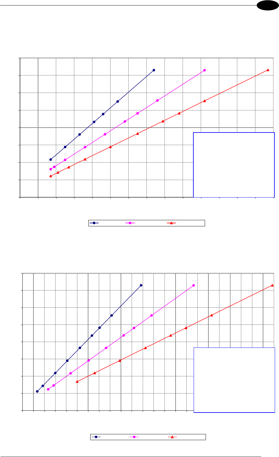
READING FEATURES
95
7
7.2.2 1D (Linear) Codes
1D Codes – Matrix 400 400-0x0 (SXGA)
9 mm, 12.5 mm, 16 mm
0
5
10
15
20
25
30
35
40
0 5 10 15 20 25 30 35 40 45 50 55 60 65 70
Reading Distance (cm)
Horizontal FOV (cm)
SXGA - 9 mm SXGA - 12.5 mm SXGA - 16 mm
0.25
0.20
0.33
0.38
0.20
0.25
0.50
0.30
0.33
0.380.38
0.50 0.50
0.33
0.300.30
0.25
0.20
0.15 0.15 0.15
0.12 0.12
0.10
1D Codes – Matrix 400 400-0x0 (SXGA)
25 mm, 35 mm, 50 mm
0
5
10
15
20
25
30
35
40
0 10 20 30 40 50 60 70 80 90 100 110 120 130 140 150 160 170 180 190 200 210 220 230
Reading Distance (cm)
Horizontal FOV (cm)
SXGA - 25 mm SXGA - 35 mm SXGA - 50 mm
0.25
0.200.20
0.25
0.30
0.33
0.38
0.25
0.50
0.30
0.33
0.38
0.38
0.50 0.50
0.33
0.30
0.15
0.10
0.15
0.10
0.20
0.15
1D Codes – Matrix 400 600-0x0 (UXGA)
Code Resolution Conversion
0.10 mm (4 mils)
0.12 mm (5 mils)
0.15 mm (6 mils)
0.20 mm (8 mils)
0.25 mm (10 mils)
0.30 mm (12 mils)
0.33 mm (13 mils)
0.38 mm (15 mils)
0.50 mm (20 mils)
Code Resolution Conversion
0.10 mm (4 mils)
0.12 mm (5 mils)
0.15 mm (6 mils)
0.20 mm (8 mils)
0.25 mm (10 mils)
0.30 mm (12 mils)
0.33 mm (13 mils)
0.38 mm (15 mils)
0.50 mm (20 mils)
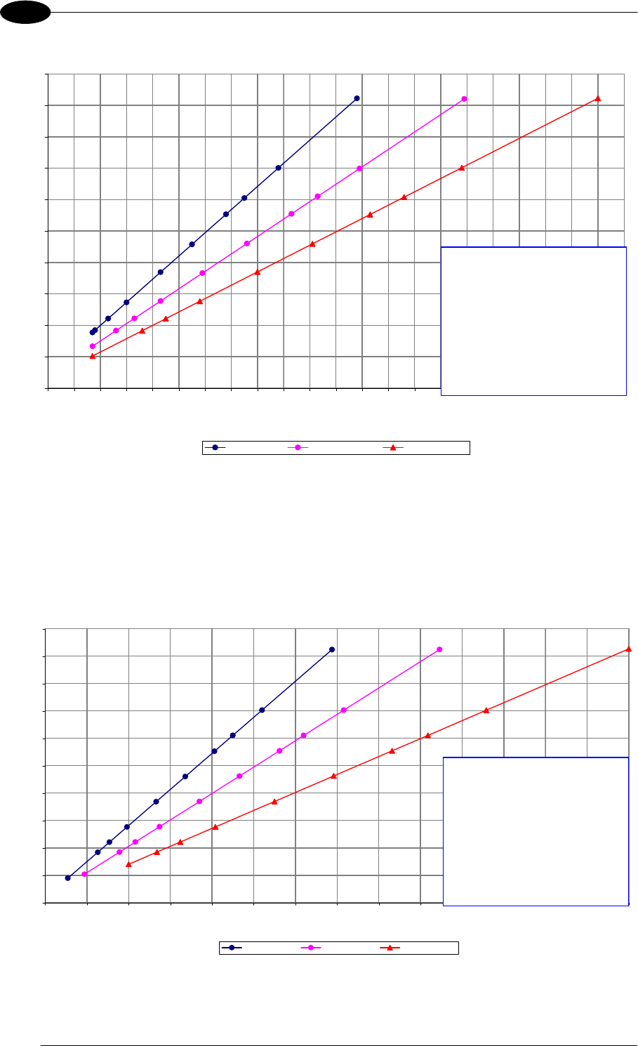
MATRIX 400™ REFERENCE MANUAL
96
7
9 mm, 12.5 mm, 16 mm
0
5
10
15
20
25
30
35
40
45
50
0 5 10 15 20 25 30 35 40 45 50 55 60 65 70 75 80 85 90 95 100 105 110
Reading Distance (cm)
Horizontal FOV (cm)
UXGA - 9 mm UXGA - 12.5 mm UXGA - 16 mm
0.15
0.25
0.200.20
0.25
0.30
0.33
0.38
0.15
0.12
0.20
0.25
0.50
0.30
0.33
0.380.38
0.50 0.50
0.33
0.30
0.10
0.12
0.10
0.15
0.12
0.10
1D Codes – Matrix 400 600-0x0 (UXGA)
25 mm, 35 mm, 50 mm
0
5
10
15
20
25
30
35
40
45
50
0 25 50 75 100 125 150 175 200 225 250 275 300 325 350
Reading Distance (cm)
Horizontal FOV (cm)
UXGA - 25 mm UXGA - 35 mm UXGA - 50 mm
0
.1
5
0.25
0.20
0.20
0.25
0.30
0
.
33
0.38
0
.1
5
0.12
0.20
0.25
0.50
0.30
0
.
33
0.38
0.38
0.50 0.50
0.33
0.30
0.15
0
.1
0
0.12
0.10
0.12
0.10
Code Resolution Conversion
0.10 mm (4 mils)
0.12 mm (5 mils)
0.15 mm (6 mils)
0.20 mm (8 mils)
0.25 mm (10 mils)
0.30 mm (12 mils)
0.33 mm (13 mils)
0.38 mm (15 mils)
0.50 mm (20 mils)
Code Resolution Conversion
0.10 mm (4 mils)
0.12 mm (5 mils)
0.15 mm (6 mils)
0.20 mm (8 mils)
0.25 mm (10 mils)
0.30 mm (12 mils)
0.33 mm (13 mils)
0.38 mm (15 mils)
0.50 mm (20 mils)
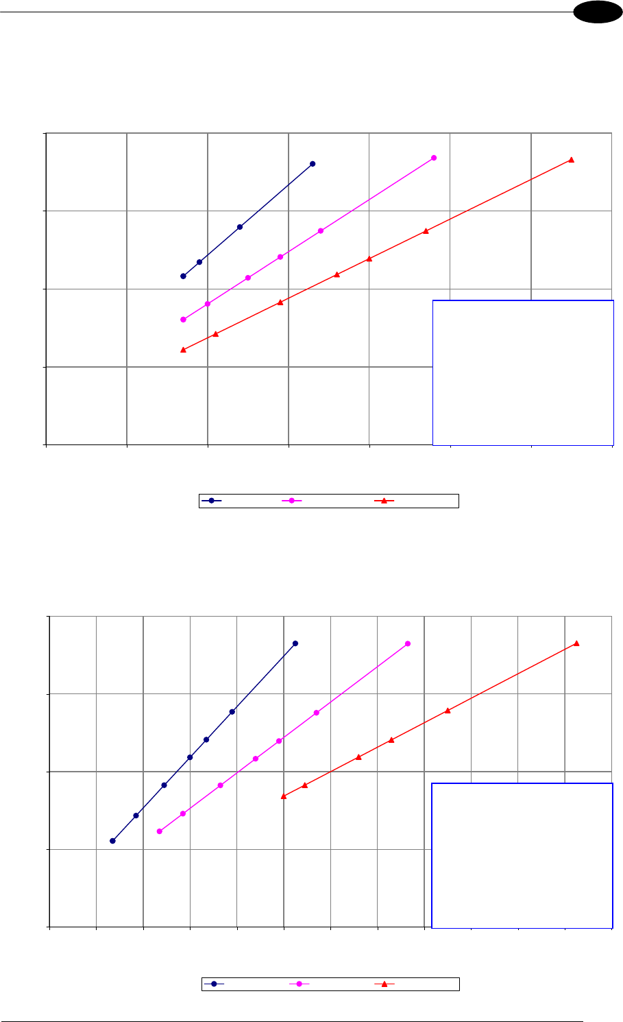
READING FEATURES
97
7
7.2.3 2D (Bi-dimensional) Codes
2D Codes – Matrix 400 400-0x0 (SXGA)
9 mm, 12.5 mm, 16 mm
0
5
10
15
20
0 5 10 15 20 25 30 35
Reading Distance (cm)
Horizontal FOV (cm)
SXGA - 9 mm SXGA - 12.5 mm SXGA - 16 mm
0.25
0.20
0.33
0.38
0.20
0.25
0.50
0.30
0.33
0.380.38
0.50 0.50
0.33
0.30
2D Codes – Matrix 400 400-0x0 (SXGA)
25 mm, 35 mm, 50 mm
0
5
10
15
20
0 10 20 30 40 50 60 70 80 90 100 110 120
Reading Distance (cm)
Horizontal FOV (cm)
SXGA - 25 mm SXGA - 35 mm SXGA - 50 mm
0.25
0.200.20
0.25
0.30
0.33
0.38
0.25
0.50
0.30
0.33
0.380.38
0.50 0.50
0.33
0.30
0.15
Code Resolution Conversion
0.10 mm (4 mils)
0.12 mm (5 mils)
0.15 mm (6 mils)
0.20 mm (8 mils)
0.25 mm (10 mils)
0.30 mm (12 mils)
0.33 mm (13 mils)
0.38 mm (15 mils)
0.50 mm (20 mils)
Code Resolution Conversion
0.10 mm (4 mils)
0.12 mm (5 mils)
0.15 mm (6 mils)
0.20 mm (8 mils)
0.25 mm (10 mils)
0.30 mm (12 mils)
0.33 mm (13 mils)
0.38 mm (15 mils)
0.50 mm (20 mils)
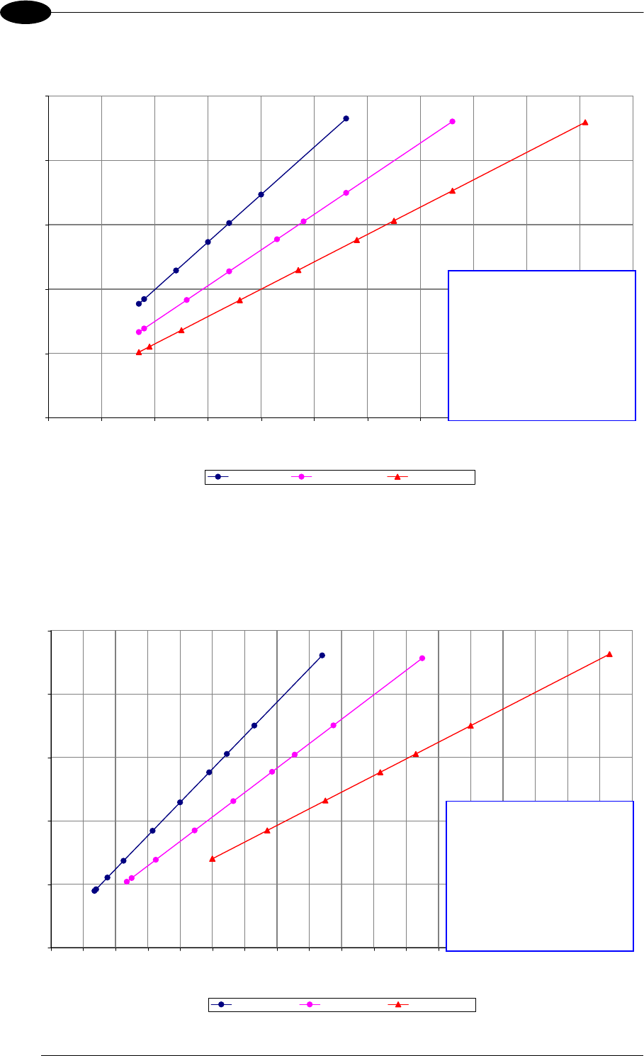
MATRIX 400™ REFERENCE MANUAL
98
7
2D Codes – Matrix 400 600-0x0 (UXGA)
9 mm, 12.5 mm, 16 mm
0
5
10
15
20
25
0 5 10 15 20 25 30 35 40 45 50 55
Reading Distance (cm)
Horizontal FOV (cm)
UXGA - 9 mm UXGA - 12.5 mm UXGA - 16 mm
0.15
0.25
0.20
0.20
0.25
0.30
0.33
0.38
0.15
0.12
0.20
0.25
0.50
0.30
0.33
0.380.38
0.50 0.50
0.33
0.30
2D Codes – Matrix 400 600-0x0 (UXGA)
25 mm, 35 mm, 50 mm
0
5
10
15
20
25
0 10 20 30 40 50 60 70 80 90 100 110 120 130 140 150 160 170 180
Reading Distance (cm)
Horizontal FOV (cm)
UXGA - 25 mm UXGA - 35 mm UXGA - 50 mm
0.15
0.25
0.200.20
0.25
0.30
0.33
0.38
0.15
0.12
0.20
0.25
0.50
0.30
0.33
0.380.38
0.50 0.50
0.33
0.30
0.15
0.10
0.12
Code Resolution Conversion
0.10 mm (4 mils)
0.12 mm (5 mils)
0.15 mm (6 mils)
0.20 mm (8 mils)
0.25 mm (10 mils)
0.30 mm (12 mils)
0.33 mm (13 mils)
0.38 mm (15 mils)
0.50 mm (20 mils)
Code Resolution Conversion
0.10 mm (4 mils)
0.12 mm (5 mils)
0.15 mm (6 mils)
0.20 mm (8 mils)
0.25 mm (10 mils)
0.30 mm (12 mils)
0.33 mm (13 mils)
0.38 mm (15 mils)
0.50 mm (20 mils)

READING FEATURES
99
7
7.3 MAXIMUM LINE SPEED AND EXPOSURE TIME CALCULATIONS
The Exposure Time (or Shutter) parameter defines the time during which the image will be
exposed to the reader sensor to be acquired. This parameter depends heavily on the
environmental conditions (external lighting system, image contrast etc.).
In general, a longer time corresponds to a lighter image but is susceptible to blurring due to
the code movement; a shorter exposure time corresponds to a darker image.
NOTE
The following considerations must be applied only when the internal
lighting system and 2D codes are used. The Maximum line speed allowed
for linear codes or postal code reading applications heavily depends on the
direction of symbol movement. When the direction of movement is parallel
to the elements of the code, the maximum speed is greater.
Assuming:
X: Code Resolution (mm)
Texp: Exposure Time (s)
LS: Line Speed (mm/s)
The essential condition to avoid blurring effects between two adjacent elements in a dynamic
reading application is:
LS Texp X
The maximum (theoretical) line speed LS can be calculated as follows:
X / Texp (max) = LS (max)
Example:
A Matrix 400™ 600-010 using:
Internal Lighting Mode = Very High Power Strobe
Exposure Time (x10
s) = 10 (100
s)
Code Resolution (X) = 0.254 mm (10 mils)
has a maximum line speed of:
0.254 (mm) / 0.0001 (s) = 2540 mm/s
Likewise, Texp (max) is the maximum Exposure Time value that can be used without blurring
for the given application line speed and code resolution. Therefore:
X / LS (max) = Texp (max)
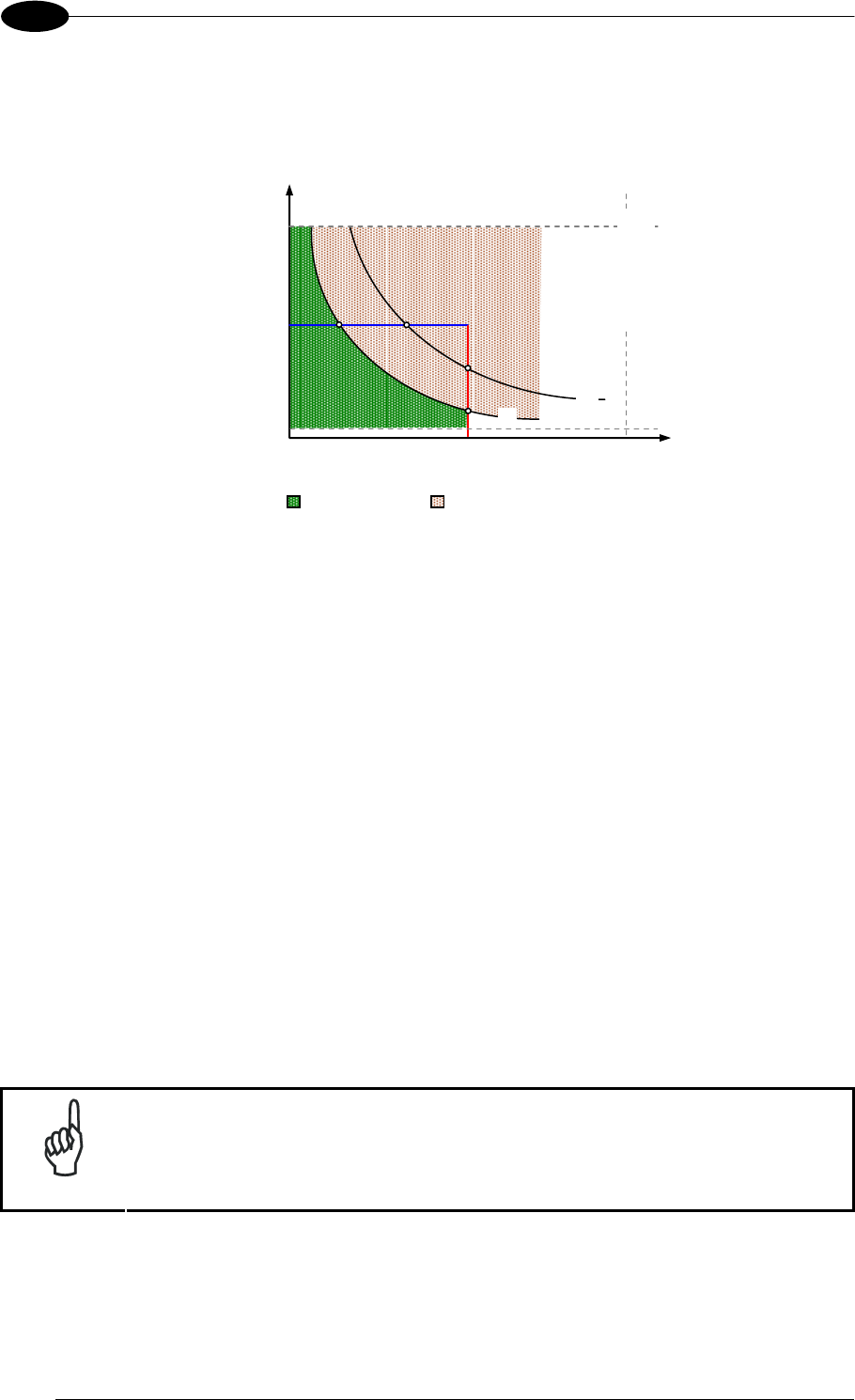
MATRIX 400™ REFERENCE MANUAL
100
7
Texp (max) and LS (max) are represented in the graph below as the curved line for X (code
resolution). Values above the curve result in blurring. In practice, the application values are
somewhere below the theoretical line, (in the green area), due to environmental and other
conditions.
Line Speed
T
exp
SW Limit
T
exp (min)
SW/HW Limit
X
2X
Conveyor Speed
Limit
Readable Blurring
For example, the maximum target speed in the application is also affected by these
conditions:
Code/Background Contrast: maximum speed decreases when decreasing image
contrast (poor quality codes, reflective transparent coverings, different supports and
printing techniques).
Code Resolution: maximum speed increases when decreasing code resolution, (i.e. 2X).
There is a decrement of overlapping effects between two adjacent elements.
Tilt Angle: maximum speed decreases when increasing Tilt angle (from 0 to 45
degrees).
The Internal Lighting Mode parameter allows setting the operating mode of the internal
lighting system. The possible values are:
Disabled: the built-in LED array is turned off all the time. This option can be useful if using
an external lighting system;
Always ON: the built-in LED array is turned on all the time at the lowest power level. This
option is useful if the LED-array blinking (Strobed operating mode) disturbs the operator.
Very High/High/Medium/Low-Power Strobed: the built-in LED array is on only during the
image exposure time. Four different lighting levels can be set.
NOTE
To avoid LED array overheating, for Power Strobed settings, the program
automatically limits the range of allowed values for the Exposure Time
parameter. Therefore, after changes to Internal Lighting Mode, recheck
Exposure Time.

READING FEATURES
101
7
Line Speed
T
exp
SW Limit
X
2X
Conveyor Speed
Limit
Readable Blurring
T
exp (min)
SW/HW Limit
Texp (min) is the minimum Exposure Time value obtainable for the specific application. It can
be evaluated in static reading conditions and depends on the Matrix reader model selected
for the application (internal lighting system, optical lens, diaphragm aperture, reading
distance) and on any external lighting system. It may also depend on code printing quality,
and reader position.

MATRIX 400™ REFERENCE MANUAL
102
8
8 SOFTWARE CONFIGURATION
Software configuration of your Matrix 400™ for static reading or simple code reading
applications can be accomplished by the Rapid Configuration procedure using the X-
PRESS™ HMI (which requires no external configuration program) or by using the VisiSet™
Setup Wizard for easy setup. These procedures are described in chapter 1.
For all other applications use VisiSet™ through the reader serial ports (or Ethernet port for
Matrix 400™ Ethernet models only).
NOTE
Before using VisiSet™ via Ethernet, it is necessary to configure Matrix 400™
Ethernet port parameters using VisiSet™ via Main or Auxiliary serial port (for
further details refer to the VisiSet™ Help on line).
8.1 VISISET™ SYSTEM REQUIREMENTS
To install and run VisiSet™ you should have a Laptop or PC that meets or exceeds the
following:
Pentium processor
Win 98/2000, NT 4.0, XP or Vista
32 MB Ram
5 MB free HD space
one free RS232 serial port with 115 Kbaud
SVGA board (800x600) or better using more than 256 colors
8.2 INSTALLING VISISET™
To install VisiSet™, proceed as follows:
1. Turn on the Laptop or PC that will be used for configuration (connected to the Matrix
400™ communication ports).
2. After Windows finishes booting, insert the CD-ROM provided.
3. Launch VisiSet™ installation by clicking Install.
4. Follow the instructions in the installation procedure.
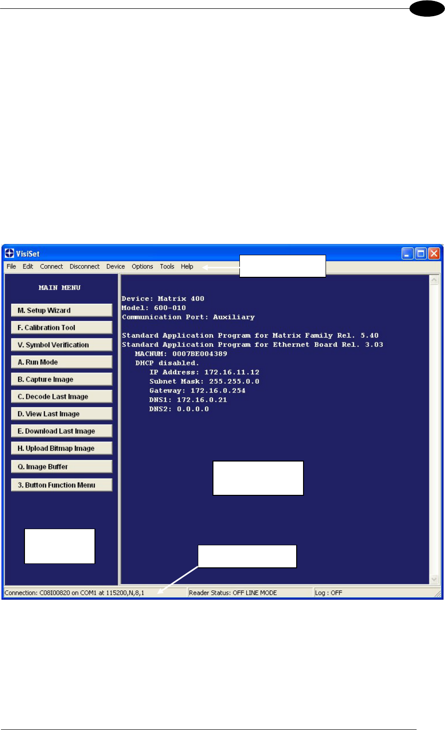
SOFTWARE CONFIGURATION
103
8
8.3 STARTUP
After completing the mechanical and electrical connections to Matrix 400™, you can begin
software configuration as follows:
1. Power on the Matrix 400™ reader. Wait for the reader startup. The system bootstrap
requires a few seconds to be completed. The reader automatically enters Run Mode.
2. Run the VisiSet™ program.
3. Press Connect on the VisiSet™ menu bar. The PC will automatically connect to the
Matrix 400™ reader.
Upon connection, Matrix 400™ exits Run Mode and displays the Main Menu on VisiSet™
with all the commands necessary to monitor your reader's performance. You can select
these commands using the mouse or by pressing the key corresponding to the letter
shown on the button. See Figure 113.
Figure 113 - Main Window
Menu Bar
Terminal
Window
Commands
Window Status Bar
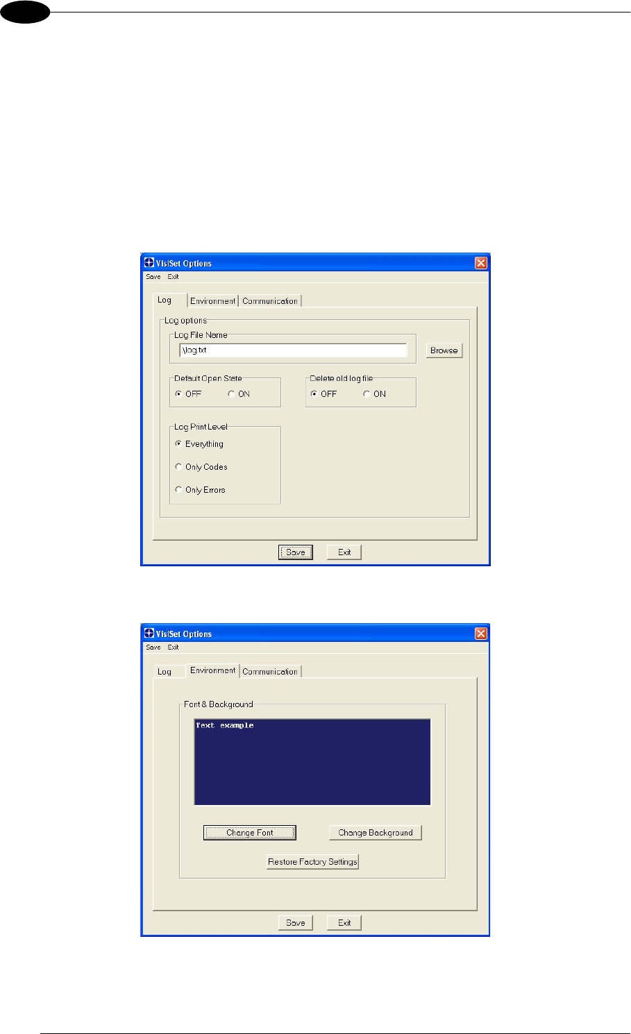
MATRIX 400™ REFERENCE MANUAL
104
8
8.3.1 VisiSet™ Options
The Options item from the VisiSet™ menu (see Figure 113) presents a window allowing you
to configure:
the logging function (Log)
VisiSet™ window properties (Environment)
VisiSet™ communication channel (Communication)
Figure 114 - Options - Log
Figure 115 - Options - Environment
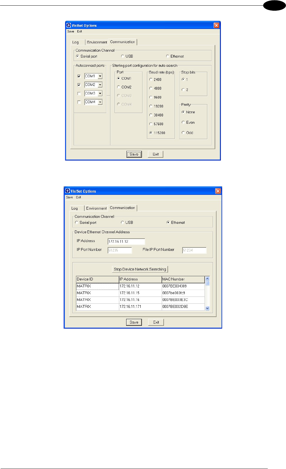
SOFTWARE CONFIGURATION
105
8
Figure 116 - Options – Communication: Serial Port
Figure 117 - Options – Communication: Ethernet

MATRIX 400™ REFERENCE MANUAL
106
8
8.4 CONFIGURATION
Once connected to Matrix 400™ as described in par. 8.3, you can modify the configuration
parameters as follows:
1. Press the Calibration Tool button from the Main Menu. Matrix 400™ will download its
permanent memory configuration parameters with the default values (if it is the first time)
to VisiSet™. The Calibration Tool window will be displayed together with the Parameter
Setup window working in Interactive Mode (see par. 8.4.1 and par. 8.4.3).
2. Edit the Matrix 400™ configuration parameters according to your application
requirements.
3. Use the Calibration Tool to fine tune the reading performance. See par. 8.4.3.
4. Close the Calibration Tool window and disable the Interactive Mode by pressing the
interactive button.
5. Save the new configuration to the reader permanent memory by pressing the Send
button.
6. Close the Parameter Setup window and press Disconnect on the VisiSet™ menu bar
(see Figure 113) or launch Run Mode from the VisiSet™ Main menu.
Disconnect exits closing communication between Matrix 400™ and VisiSet™, and
causes Matrix 400™ to enter Run Mode. The disconnected reader serial port is now
available.
Run command does not close communication between Matrix 400™ and VisiSet™,
and causes Matrix 400™ to enter Run Mode. In this case the reader output messages
are displayed on the VisiSet™ terminal and the statistics are displayed in the
Statistics window (Statistics enabled).
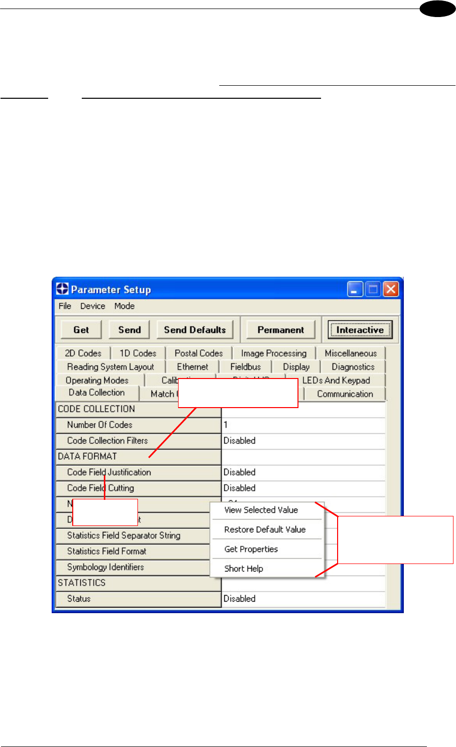
SOFTWARE CONFIGURATION
107
8
8.4.1 Edit Reader Parameters
The Parameter Setup window displays the configuration parameters grouped in a series of
folders. Each parameter can be modified by selecting a different item from the prescribed list
in the box, or by typing new values directly into the parameter box.
By right clicking the mouse when positioned over the name of a specific Parameter or Group,
a pop-up menu appears allowing you to directly manage that particular parameter or group.
You can View the Selected Value for each parameter.
You can Restore the Default Value of each parameter or of all the parameters of a group.
Get Properties gives information about the parameter in the form of a pop-up hint that
describes the default value and the range/list of valid values.
The Short Help gives information about the parameter in the form of a pop-up hint.
Figure 118 - Editing Parameters
Parameter
Parameter Group
Single group/parameter
management
(right click)

MATRIX 400™ REFERENCE MANUAL
108
8
Parameters to verify/modify:
Operating Mode Sets the parameters which customize the reader operating mode
starting from three main modes:
One Shot: acquires a single image based on the selected value
for the Acquisition Trigger and Acquisition Trigger Delay.
Continuous: continuously acquires images with a rate up to the
maximum allowable frame rate per second for the given sensor
depending on the decoding time and the Region of Interest
settings.
Phase Mode: acquires images during the reading phase
depending on the selected value for the Acquisition Trigger and
Acquisition Trigger Delay. The Reading Phase-ON and Reading
Phase-OFF events mark respectively the beginning and end of
the reading phase.
Calibration Calibrates the acquisition parameters to maximize the reading
performance (see par. 8.4.3).
Communication Configures the parameters relative to each serial port regarding
the transmission, message formatting and string receiving.
Any change to the VisiSet™ communication port parameters
(baud rate, data bits, etc.) is effective as soon as the reader is
disconnected from VisiSet™.
Ethernet Sets the parameters related to the Ethernet interface and to its
communication channels.
Fieldbus Sets the parameters related to the External Fieldbus interface
through the CBX500 and to its communication channels.
Display Sets the Display language and Layout of the BM150 Display
when using the CBX500 connection box.
Diagnostics Enables various diagnostic messages, formatting and actions.
Reading System Layout Allows configuring the device according to the desired layout:
Standalone, ID-NET™ or Master/Slave RS232
Image Processing Sets the image processing parameters shared by all available
symbologies.
1D & 2D, Postal Codes Sets the characteristics of the code symbologies to be read.
Data Collection Defines the code-collection parameters and the output message
format.
Digital I/O Configures the reader input/output parameters.
Match Code Allows setting a user-defined code and relative parameters to
which the read code will be compared (matched).
Miscellaneous Sets the reader name and the saved image format.
Symbol Verification Sets the parameters relative to the various specifications in the
Standards which regulate code validation.
LEDs And Keypad Sets the X-PRESS™ LED and Keypad parameters related to their
selected Functions: Beeper, Green Spot, Setup, Positioning, etc.
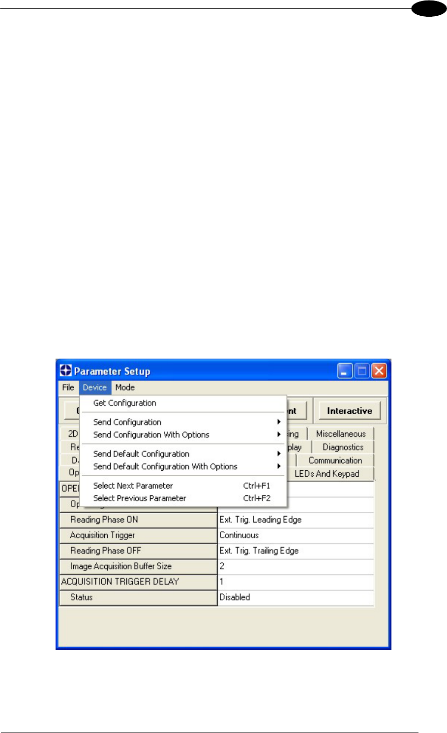
SOFTWARE CONFIGURATION
109
8
When all the configuration parameters are set correctly, save them to the Matrix 400™
reader by pressing the Send button. See Figure 118.
For successive configuration of other readers or for backup/archive copies, it is possible to
save the configuration onto your PC by selecting the Save Configuration File option from
the File menu.
From the File menu, you can also Save Configuration As Text File for a human readable
version.
Load Configuration File (available in the File menu) allows you to configure a reader from a
previously saved configuration file (.ini).
8.4.2 Send Configuration Options
The device parameters are divided into two main classes, Configuration and Environmental
which are effected differently by the Send Configuration and Send Default Configuration
commands.
Configuration Parameters regard parameters that are specific to the device. These
parameters are influenced by the Send Configuration and Send Default Configuration
commands, that is they are overwritten by these commands. The same parameters are
modified by the following "Send Configuration with Options" and "Send Default Configuration
with Options" dialogs from the Device Menu:

MATRIX 400™ REFERENCE MANUAL
110
8
Environmental Parameters regard the device Identity and Position in a Network (ID-NET™,
Master/Slave RS232, MUX 32, Ethernet) and are not influenced by the "Send Default
Configuration" and "Send Configuration" commands. This allows individual devices to be
configured differently without affecting their recognized position in the network.
The following is a list of the Environmental Parameters:
READING SYSTEM LAYOUT
- Device Network Setting
- Number of Slaves
DEVICE NETWORK SETTINGS
- Topology Role
- ID-NET Slave Address
- Network Baud Rate
EXPECTED SLAVE DEVICES
- Status
- Device Description
- Device Network Name
MAIN PORT
- Communication Protocol
- Multidrop Address
ETHERNET SYSTEM
- Status
- DHCP Client
- IP Address
- Subnet Mask
- Gateway Address
- DNS1 Address
- DNS2 Address
MISCELLANEOUS
- Reader Name
- User Name
- Line Name
- Lens Type & S/N
- Internal Lighting System & S/N
- Diaphragm Aperture
- Focus Distance (mm)
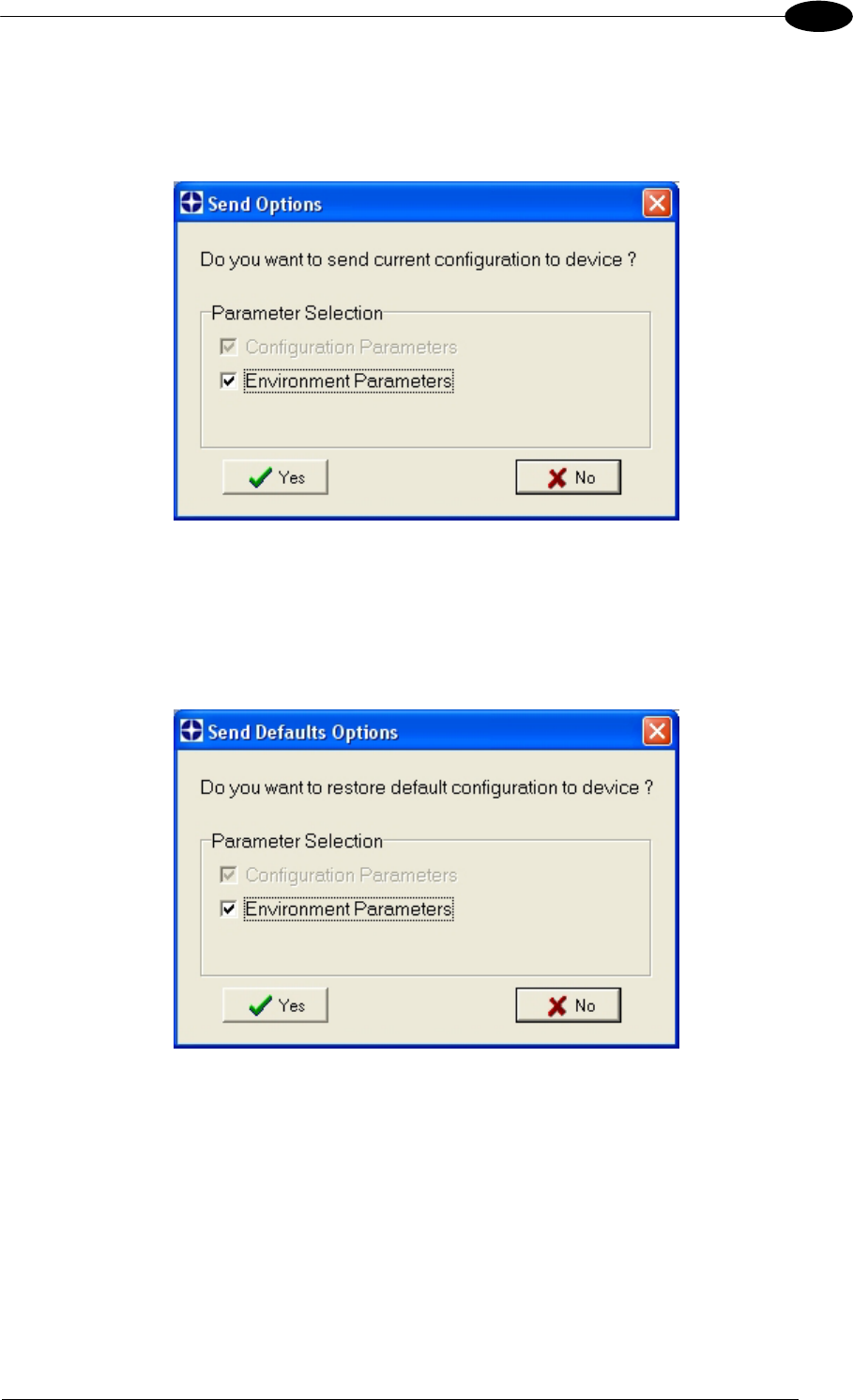
SOFTWARE CONFIGURATION
111
8
For device replacement it is necessary to send the previously saved configuration (both
Configuration and Environmental parameters) to the new device. To do this select "Send
Configuration with Options" from the Device Menu and check the Environmental Parameters
checkbox:
In order to return a device to its absolute default parameters including Environmental
parameters, the following Send Default Configuration with Options" dialog must be used:
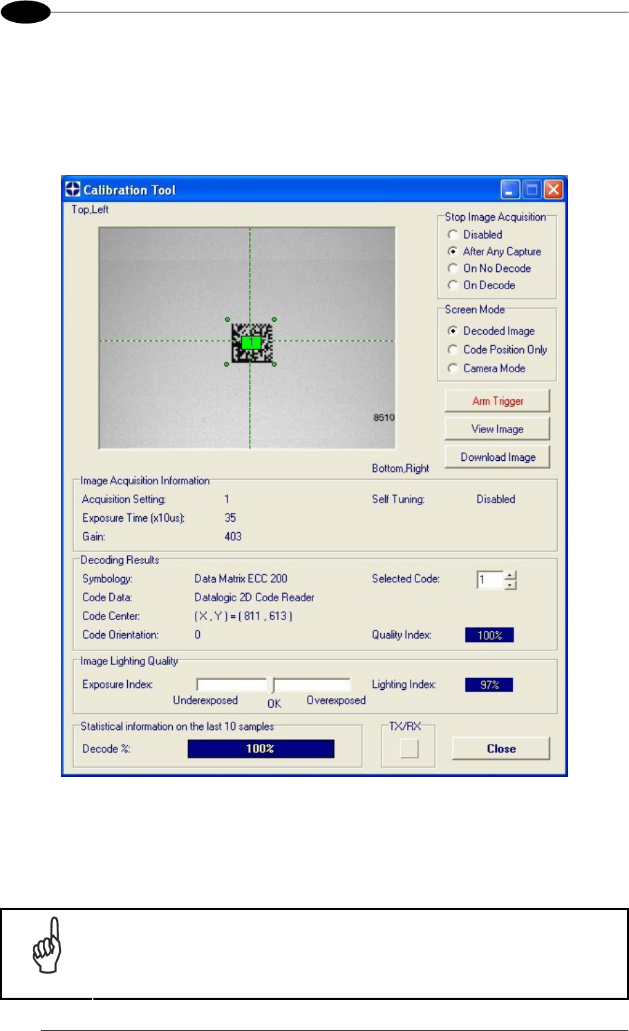
MATRIX 400™ REFERENCE MANUAL
112
8
8.4.3 Calibration
VisiSet™ provides a Calibration Tool to maximize the reading performance by tuning the
acquisition parameters and the time of the delayed triggers.
By selecting the Calibration Tool from the VisiSet™ Main Menu (F), the following window
appears together with the Parameter Setup window:
Figure 119 - Calibration OK
This tool provides a "real-time" image display while Matrix 400™ is reading. It also gives
immediate results on the performance of the installed Matrix 400™ reader.
The Parameter Setup window works in Interactive Mode in order to cause each parameter
setting to be immediately effective.
NOTE
If you want to save the temporary configuration to permanent memory, you
must first close the Calibration Tool window. Then, you must disable the
Interactive Mode and select the Permanent Memory option from the Send
Configuration item in the Device menu.
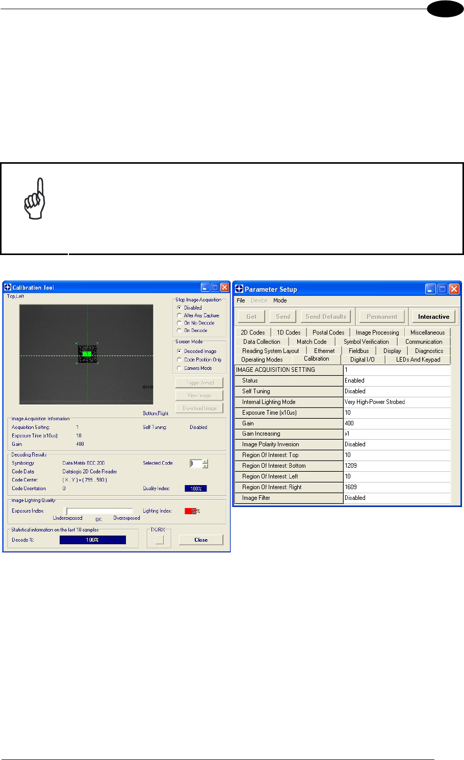
SOFTWARE CONFIGURATION
113
8
The following examples show some of the typical conditions occurring during the installation:
Under-exposure:
To correct this result it is recommended to change the following parameters in their order of
appearance:
1. increase the Exposure Time
2. increase the Gain
NOTE
In general, a longer exposure time corresponds to a lighter image but is
susceptible to blurring due to code movement. Exposure time is also
limited by the Internal Lighting mode parameter. Longer esposure times
can be set if the power strobe level is lowered.
High gain settings may produce a grainy image that may affect the
decoding process.
Figure 120 - Example Under Exposure: Too Dark
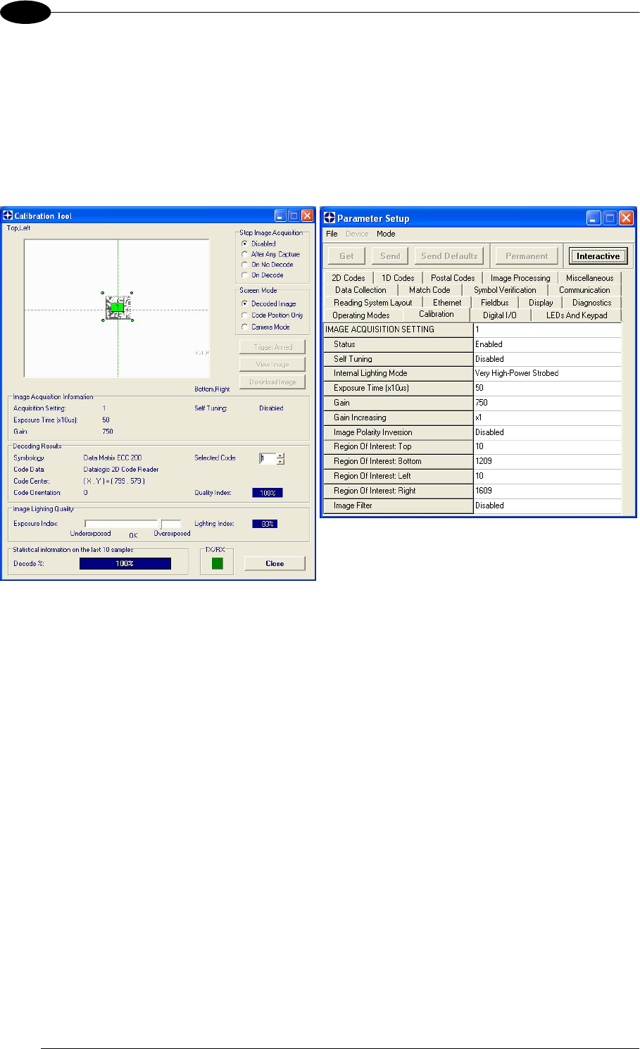
MATRIX 400™ REFERENCE MANUAL
114
8
Over-exposure:
To correct this result it is recommended to change the following parameters in their order of
appearance:
1. decrease the Gain
2. decrease the Exposure Time
Figure 121 - Example Over Exposure: Too Light
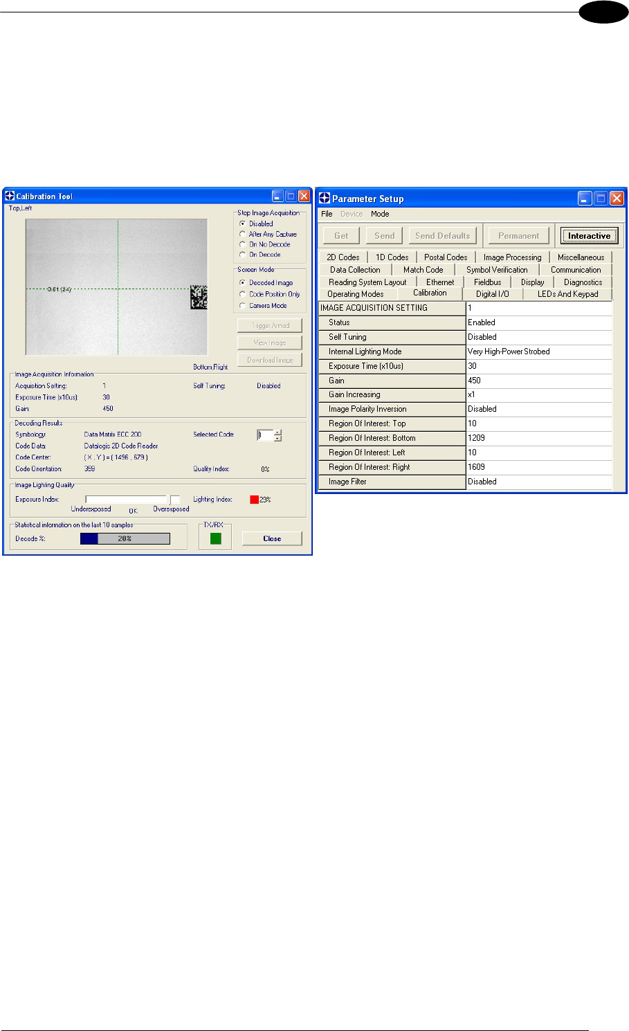
SOFTWARE CONFIGURATION
115
8
Moving code out of the Field of View:
To correct this result and have the code completely visible in F.O.V., it is possible to follow
one or both the procedures listed below:
reposition the reader
use the Acquisition Trigger Delay by tuning the Delay Time (x100µs)
Figure 122 - Example out of FOV

MATRIX 400™ REFERENCE MANUAL
116
8
8.4.4 Multi Image Acquisition Settings
When controlled variable conditions occur in the application, Multiple Image Acquisition
Settings (up to 10), can be defined to create a database of parameter groups that handle
each specific application condition. This database of pre-defined settings functions cyclically
and therefore automatically improves system flexibility and readiness.
For example, an application may have two stable but different lighting conditions which
require different lighting options. One Image Acquisition Setting could enable and use an
internal illuminator and a second setting could enable and use an external lighting system.
These two groups will be used cyclically on each acquisition in order to automatically capture
the correctly lighted image.
Image Acquisition Settings are found in the VisiSet™ Calibration parameter setup menu.
By selecting a different number and enabling its Status you can define the parameters for a
new group.
8.4.5 Run Time Self Tuning (RTST)
Run Time Self-Tuning (RTST) increases Matrix’s flexibility in the presence of uncontrolled
variable conditions (lighting, code contrast, etc.) by automatically adjusting its acquisition
parameters.
Self Tuning Calibration
In the Calibration parameter setup menu, the Self Tuning parameters manage the Image
Acquisition Setting parameters dynamically. Self Tuning provides automatic adjustment in
run time of different acquisition parameters (Exposure Time and/or Gain) for each captured
image based on calculations performed on previous acquisitions. These dynamic settings will
be used instead of the static settings saved in memory.
From
Not Readable
to
Readable
For more details see the Matrix 400™ Help On-Line.
Self Tuning Image Processing
In the Image Processing parameter setup menu, the Self Tuning parameters manage the
Image Processing and Symbology related parameters. They perform different processing
attempts on the same captured image according to the selected Self Tuning Mode parameter
value: (Symbologies Only, Processing Modes Only, Decoding Methods Only, Code Contrast
Levels Only, Image Mirroring Only, or General Purpose).
For more details see the Matrix 400™ Help On-Line.
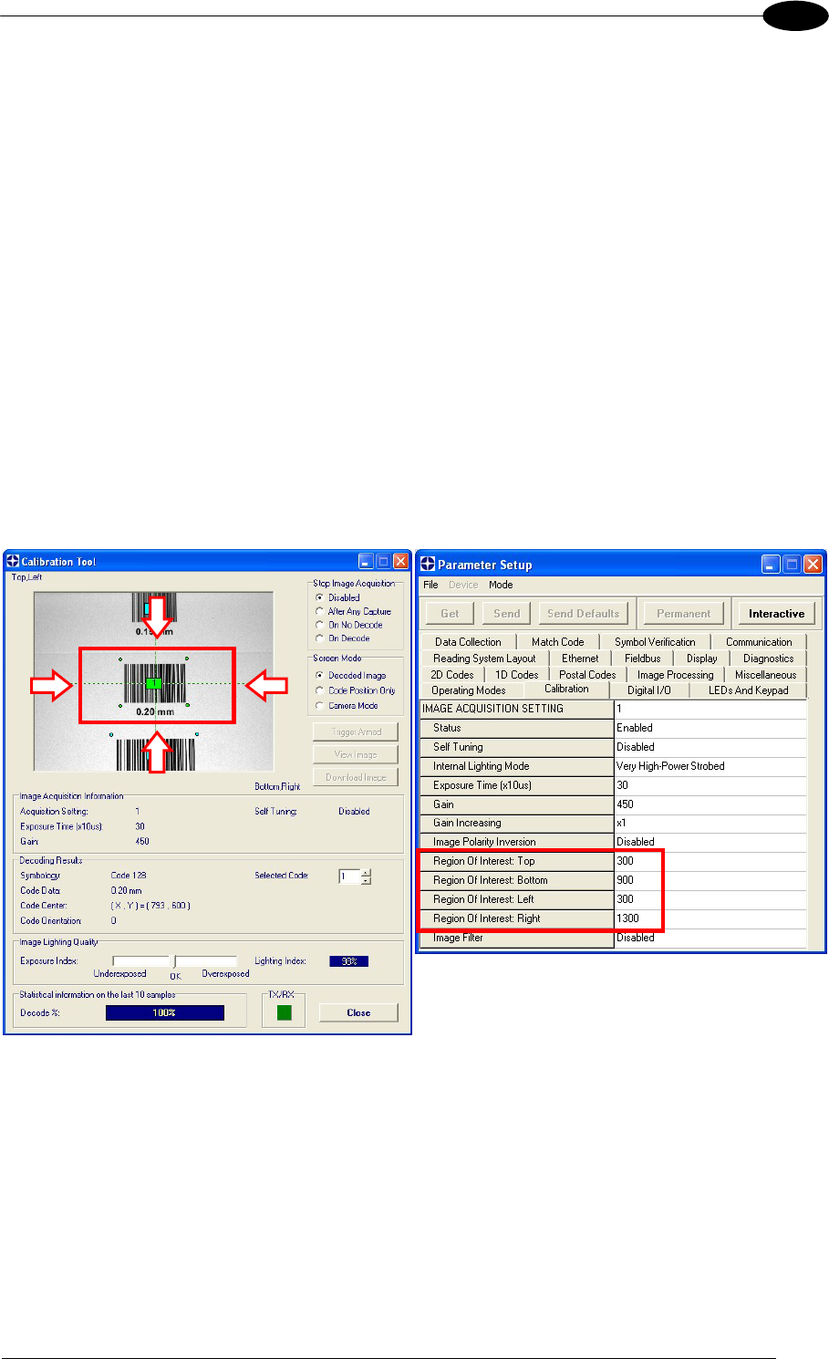
SOFTWARE CONFIGURATION
117
8
8.4.6 Region Of Interest Windowing
In order to satisfy very high throughput applications, higher frame rates can be achieved
using the powerful Region Of Interest Windowing parameters in the Calibration parameter
setup menu.
Region Of Interest Windowing allows defining a region or window within the reader FOV.
The Top, Bottom, Left and Right parameters allow to precisely define the image window to
be processed, visualized and saved.
In Matrix 400™ 600-0x0 models the frame rate is dependent on the number of lines (or rows)
in the defined window.
In Matrix 400™ 400-0x0 models the frame rate is dependent on the number of rows and
columns in the defined window.
The smaller the window, the lower the frame period and consequently the higher the frame
rate. In general the Image Processing time can be reduced by reducing the window
dimensions.
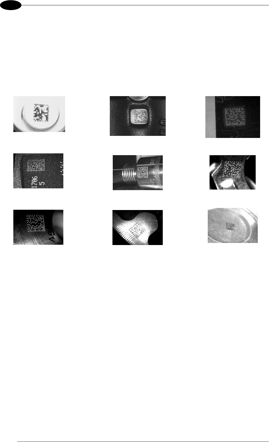
MATRIX 400™ REFERENCE MANUAL
118
8
8.4.7 Direct Part Marking Applications
Decoding Method: Direct Marking
For DataMatrix and QR code the Decoding Method parameter selects the decoding
algorithm according to the printing/marking technique used to create the symbol and on the
overall printing/marking quality. The Direct Marking selection improves the decode rate for
low quality Direct Part Mark codes and in general for Direct Part Mark codes with dot peening
type module shapes.
Washed out and Axial
Distortion Dot Peening On
Scratched Surface Low Contrast
Problem
Background
Problems Marked On Curved
Shiny Surface
Axial
distortion
Half moon effects Shiny surface,
noisy background
Low contrast,
noisy background
All the previous examples are successfully read selecting the Direct Marking Decoding
Method.
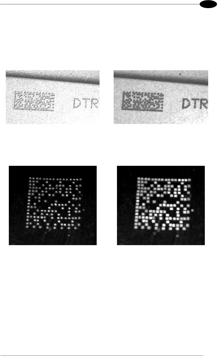
SOFTWARE CONFIGURATION
119
8
Image Filter
Sets the filter to be applied to the image before being processed. This parameter can be
used to successfully decode particular ink-spread printed codes (ex. direct part mark codes).
A different filter can be applied to each Image Acquisition Setting.
The Erode Filter enlarges the image dark zones to increase readability.
Before - No Read After - Readable
Erode
The Dilate Filter enlarges the image white zones to increase readability.
Before - No Read After - Readable
Dilate
The Close filter eliminates dark areas (defects) in the white zones of the image.
The Open filter eliminates white areas (defects) in the dark zones of the image.
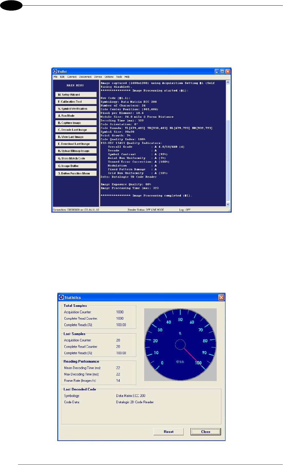
MATRIX 400™ REFERENCE MANUAL
120
8
8.5 IMAGE CAPTURE AND DECODING
By using the Capture Image and Decode Last Image functions from the VisiSet™ Main
menu, you can get information about the image decodable codes in terms of Symbology,
encoded Data, Position and Orientation, Decode Time and Code Quality Assessment Metrics.
Figure 123 - Capture and Decoding Functions
8.6 STATISTICS
Statistics on the reading performance can be viewed by enabling the Statistics parameter
and selecting the View Statistics item in the File menu. One of three different windows
appears depending on the operating mode.
Refer to the VisiSet™ Help On Line for more details.
Figure 124 - Code Statistics

MAINTENANCE
121
9
9 MAINTENANCE
9.1 CLEANING
Clean the reading window (see Figure A, 1) periodically for continued correct operation of the
reader.
Dust, dirt, etc. on the window may alter the reading performance.
Repeat the operation frequently in particularly dirty environments.
Use soft material and alcohol to clean the window and avoid any abrasive substances.

MATRIX 400™ REFERENCE MANUAL
122
10
10 TROUBLESHOOTING
10.1 GENERAL GUIDELINES
When wiring the device, pay careful attention to the signal name (acronym) on the
CBX100/500 spring clamp connectors (chp. 4). If you are connecting directly to the
Matrix 400™ M16 19-pin connector pay attention to the pin number of the signals (chp. 5).
If you need information about a certain reader parameter you can refer to the VisiSet
program help files. Either connect the device and select the parameter you’re interested in
by pressing the F1 key, or select Help>Paramters Help from the command menu.
If you’re unable to fix the problem and you’re going to contact your local Datalogic office or
Datalogic Partner or ARC, we suggest providing (if possible): Application Program version,
Parameter Configuration file, Serial Number and Order Number of your reader. You can
get this information while VisiSet™ is connected to the reader: the Application Program
version is shown in the Terminal Window; the Parameter Configuration can be saved to an
.ini file applying the File>Save Configuration File command in the Parameter Setup
window; Serial Number and Order Number can be obtained by applying the respective
command in the Tools menu.
TROUBLESHOOTING GUIDE
Problem Suggestion
Power ON:
the “POWER” LED is not lit.
Is power connected?
If using a power adapter (like PG6000), is it connected
to wall outlet?
If using rail power, does rail have power?
If using CBX, does it have power (check switch and
LED)?
Check if you are referring to the M16 19-pin connector
or to the CBX spring clamp connectors.
Measure Voltage either at pin A and pin L (for 19-pin
connector) or at spring clamp Vdc and GND (for CBX).
One Shot or Phase Mode
using the Input 1 (External
Trigger) or Input 2:
the ”TRIGGER” LED is not
blinking while the External
Trigger is switching.
Check if you are referring to the 19-pin connector or to
the CBX spring clamp connectors.
Is the sensor connected to the Input 1 or Input 2?
Is power supplied to the photo sensor?
For NPN configuration, is power supplied to one of the
two I1 or I2 signals (A or B)?
For PNP configuration, is one of the two I1 or I2 signals
grounded (A or B)?
Are the photo sensor LEDS (if any) working correctly?
Is the sensor/reflector system aligned (if present)?
In the Digital I/O folder check the EXTERNAL
TRIGGER or INPUT 2\Debounce Filter parameter
setting.
In the Operating Mode folder check the settings for
Reading Phase-ON, Acquisition Trigger and
Reading Phase-OFF parameters.

TROUBLESHOOTING
123
10
TROUBLESHOOTING GUIDE
Problem Suggestion
One Shot or Phase Mode
using serial trigger source:
the ”TRIGGER” LED is not
blinking.
In the Operating Mode folder check the settings for
Reading Phase-ON, Acquisition Trigger and
Reading Phase-OFF parameters.
Are the COM port parameters (Baud Rate, Parity, Data
Bits, Stop Bits, Handshake) correctly assigned?
In the communication folder, check the settings of
Reading Phase-ON String, Acquisition Trigger
String and Reading Phase-OFF String parameters.
Is the serial trigger source correctly connected?
Phase Mode:
the ”TRIGGER" LED is
correctly blinking but no image
is displayed in VisiSet™
Calibration Tool window.
Is the Phase frequency lower than the maximum frame
rate?
Continuous Mode:
the ”TRIGGER” LED is not
blinking.
Verify the correct software configuration settings.
Any Operating Mode:
the ”TRIGGER” LED is
correctly blinking but no result
is transmitted by the reader at
the end of the reading phase
collection.
In the Data Collection folder check the settings for the
CODE COLLECTION, DATA FORMAT and
STATISTICS parameter groups.
Image not clear: verify the Focus procedure
Image focused but not
decoded:
verify the Calibrate Image Density prodcedure.
Reading:
the reader always transmits
the No Read Message
Run the Rapid Configuration procedure in chapter 1.
Position the reader as described in par. 3.3 and through
the VisiSet™ Calibration Tool:
Tune the ACQUISITION TRIGGER DELAY, if the
moving code is out of the reader field of view;
Set the Continuous Operating Mode if no external
trigger source is available;
Tune the IMAGE ACQUISITION SETTING to
improve the code image quality;
Check the parameter setting in Decoding,
2D Codes, 1D Codes, and Postal Codes folders;
View the full resolution code image to check the
printing or marking quality.
Communication:
reader is not transmitting
anything to the host.
Is the serial cable wiring correct?
If using CBX, be sure the RS485 termination switch is
OFF.
Are the host serial port settings the same as the reader
serial port settings?
In VisiSet™ Digital I/O folder, "COM" LED can be
configured to indicate MAIN COM port TX or MAIN
COM port RX.
Communication:
data transferred to the host
Are the host serial port settings the same as the reader
serial port settings?

MATRIX 400™ REFERENCE MANUAL
124
10
TROUBLESHOOTING GUIDE
Problem Suggestion
are incorrect, corrupted or
incomplete. In VisiSet Communication folder check the settings of
Header and Terminator String parameters.
In VisiSet™ Data Collection folder, check the settings of
DATA FORMAT parameter group.
How do I obtain my reader
Serial Number?
The reader Serial Number consists of 9 characters: one
letter, 2 numbers, another letter followed by 5 numbers.
The reader Serial Number is printed on a label that is
affixed on the bottom case near the reading window.
The Serial Number can also be obtained by selecting
Tools/Get Reader Serial Number from the command
menu in VisiSet. A dedicated window will appear.
How do I obtain my reader
Order Number?
The reader Order Number consists of 9 numbers.
The reader Order Number can be obtained by selecting
the Tools/Get Reader Order Number from the command
menu in VisiSet. A dedicated window will appear.

TECHNICAL FEATURES
125
11
11 TECHNICAL FEATURES
ELECTRICAL FEATURES
Power
Supply Voltage 10 to 30 Vdc
Power Consumption 0.8 to 0.27 A, 8 W max.; 0.5 to 0.17 A, 5 W typical
Communication Interfaces
Main
- RS232
- RS485 full-duplex
- RS485 half-duplex
2400 to 115200 bit/s
2400 to 115200 bit/s
2400 to 115200 bit/s
Auxiliary - RS232 2400 to 115200 bit/s
ID-NET™ Up to 1MBaud
Ethernet (Ethernet Models only) 10/100 Mbit/s
Inputs
Input 1 (External Trigger) and Input 2 Opto-coupled and polarity insensitive
Max. Voltage 30 Vdc
Max. Input Current 10 mA
Outputs
Output 1 and Output 2 Opto-coupled
VOut (ILoad = 0 mA) Max. 30 Vdc
VOut (ILoad = 10 mA) Max. 1.8 Vdc
PD = VOut ILoad Max. 170 mW
OPTICAL FEATURES 4xx-xxx models 6xx-xxx models
Image Sensor CMOS CCD
Image Format SXGA (1280x1024) UXGA (1600x1200)
Frame Rate 27 frames/sec. 15 frames/sec.
Pitch 35°
Tilt 0° - 360°
Lighting System Internal or External Illuminator (accessories)
LED Safety Class Class 1 to EN60825-1
ENVIRONMENTAL FEATURES
Operating Temperature 0 to 50 C (32 to 122 °F)
(high ambient temperature applications should use metal mounting bracket for
heat dissipation)
Storage Temperature -20 to 70 C (-4 to 158 °F)
Max. Humidity 90% non condensing
Vibration Resistance 14 mm @ 2 to 10 Hz; 1.5 mm @ 13 to 55 Hz;
EN 60068-2-6 2 g @ 70 to 200 Hz; 2 hours on each axis
Bump Resistance 30g; 6 ms;
EN 60068-2-29 5000 shocks on each axis
Shock Resistance 30g; 11 ms;
EN 60068-2-27 3 shocks on each axis
Protection Class
EN 60529
IP67 *
PHYSICAL FEATURES
Dimensions 123 x 60.5 x 87 mm (4.85 x 2.38 x 3.43 in.) with lens cover
Weight 482 g. (17 oz.) with lens and internal illuminator
Material Aluminium
* when correctly connected to IP67 cables with seals and the Lens Cover is correctly mounted.

MATRIX 400™ REFERENCE MANUAL
126
11
SOFTWARE FEATURES
Readable Code Symbologies
1-D and stacked 2-D POSTAL
PDF417 Standard and Micro PDF417
Code 128 (EAN 128)
Data Matrix ECC 200
(Standard and Direct Marking)
Australia Post
Royal Mail 4 State Customer
Code 39 (Standard and Full ASCII)
Interleaved 2 of 5
QR Code
(Standard and Direct Marking)
Kix Code
Japan Post
Codabar MAXICODE PLANET
Code 93 Aztec Code POSTNET
Pharmacode
EAN-8/13 - UPC-A/E
(including Addon 2 and Addon 5)
GS1 DataBar (RSS) Family
Composite Symbologies
Microglyph
(this symbology requires an
activation procedure – contact your
local Datalogic Automation
distributor for details)
POSTNET (+BB)
Intelligent Mail
Operating Mode ONE SHOT, CONTINUOUS, PHASE MODE
Configuration Methods
X-PRESS™ Human Machine Interface
Windows-based SW (VisiSet™) via serial or Ethernet link
Serial Host Mode Programming sequences
Parameter Storage Permanent memory (Flash)
CODE QUALITY VERIFICATION
Standard Supported Symbologies
ISO/IEC 16022 Data Matrix ECC 200
ISO/IEC 18004 QR Code
ISO/IEC 15415 Data Matrix ECC 200, QR Code
ISO/IEC 15416 Code 128, Code 39, Interleaved 2 of 5, Codabar, Code 93, EAN-8/13, UPC-A/E
AS9132A Data Matrix ECC 200
AIM DPM Data Matrix ECC 200, QR Code
USER INTERFACE
LED Indicators Power, Ready, Good; Trigger; Com, Status, (Ethernet Network); (Green Spot)
Keypad Button Configurable via VisiSet™

127
GLOSSARY
AIM
(Association for Automatic Identification and Mobility): AIM Global is the international trade
association representing automatic identification and mobility technology solution providers.
AIM DPM Quality Guideline
Standard applicable to the symbol quality assessment of direct part marking (DPM)
performed in using two-dimensional bar code symbols. It defines modifications to the
measurement and grading of several symbol quality parameters.
AS9132
Standard defining uniform quality and technical requirements for direct part marking (DPM)
using Data Matrix symbologies.
Barcodes (1D Codes)
A pattern of variable-width bars and spaces which represents numeric or alphanumeric data
in machine-readable form. The general format of a barcode symbol consists of a leading
margin, start character, data or message character, check character (if any), stop character,
and trailing margin. Within this framework, each recognizable symbology uses its own unique
format.
BIOS
Basic Input Output System. A collection of ROM-based code with a standard API used to
interface with standard PC hardware.
Bit
Binary digit. One bit is the basic unit of binary information. Generally, eight consecutive bits
compose one byte of data. The pattern of 0 and 1 values within the byte determines its
meaning.
Bits per Second (bps)
Number of bits transmitted or received per second.
Byte
On an addressable boundary, eight adjacent binary digits (0 and 1) combined in a pattern to
represent a specific character or numeric value. Bits are numbered from the right, 0 through
7, with bit 0 the low-order bit. One byte in memory can be used to store one ASCII character.
Composite Symbologies
Consist of a linear component, which encodes the item's primary data, and an adjacent 2D
composite component, which encodes supplementary data to the linear component.
Dark Field Illumination
Lighting of surfaces at low angles used to avoid direct reflection of the light in the reader’s
lens.
Decode
To recognize a barcode symbology (e.g., Codabar, Code 128, Code 3 of 9, UPC/EAN, etc.)
and analyze the content of the barcode scanned.

128
Depth of Field
The difference between the minimum and the maximum distance of the object in the field of
view that appears to be in focus.
Diffused Illumination
Distributed soft lighting from a wide variety of angles used to eliminate shadows and direct
reflection effects from highly reflective surfaces.
Direct Part Mark (DPM)
A symbol marked on an object using specific techniques like dot peening, laser etching,
chemical etching, etc.
EEPROM
Electrically Erasable Programmable Read-Only Memory. An on-board non-volatile memory
chip.
Element
The basic unit of data encoding in a 1D or 2D symbol. A single bar, space, cell, dot.
Exposure Time
For digital cameras based on image sensors equipped with an electronic shutter, it defines
the time during which the image will be exposed to the sensor to be acquired.
Flash
Non-volatile memory for storing application and configuration files.
Host
A computer that serves other terminals in a network, providing services such as network
control, database access, special programs, supervisory programs, or programming
languages.
Image Processing
Any form of information processing for which the input is an image and the output is for
instance a set of features of the image.
Image Resolution
The number of rows and columns of pixels in an image. The total number of pixels of an
image sensor.
Image Sensor
Device converting a visual image to an electric signal. It is usually an array of CCD (Charge
Coupled Devices) or CMOS (Complementary Metal Oxide Semiconductor) pixel sensors.
IEC
(International Electrotechnical Commission): Global organization that publishes international
standards for electrical, electronic, and other technologies.
IP Address
The terminal’s network address. Networks use IP addresses to determine where to send
data that is being transmitted over a network. An IP address is a 32-bit number referred to as
a series of 8-bit numbers in decimal dot notation (e.g., 130.24.34.03). The highest 8-bit
number you can use is 254.

129
ISO
(International Organization for Standardization): A network of the national standards
institutes of several countries producing world-wide industrial and commercial standards.
LED (Light Emitting Diode)
A low power electronic light source commonly used as an indicator light. It uses less power
than an incandescent light bulb but more than a Liquid Crystal Display (LCD).
LED Illuminator
LED technology used as an extended lighting source in which extra optics added to the chip
allow it to emit a complex radiated light pattern.
Matrix Symbologies (2D Codes)
An arrangement of regular polygon shaped cells where the center-to-center distance of
adjacent elements is uniform. Matrix symbols may include recognition patterns which do not
follow the same rules as the other elements within the symbol.
Multidrop
A communication protocol for connecting two or more readers in a network with a
concentrator (or controller) and characterized by the use of individual device addresses.
Multi-row (or Stacked) Symbologies
Symbologies where a long symbol is broken into sections and stacked one upon another
similar to sentences in a paragraph.
RAM
Random Access Memory. Data in RAM can be accessed in random order, and quickly
written and read.
Symbol Verification
The act of processing a code to determine whether or not it meets specific requirements.
Transmission Control Protocol/Internet Protocol (TCP/IP)
A suite of standard network protocols that were originally used in UNIX environments but are
now used in many others. The TCP governs sequenced data; the IP governs packet
forwarding. TCP/IP is the primary protocol that defines the Internet.

130
INDEX
A
Accessories, 31
Application Examples, 32
Auxiliary RS232 Interface, 55, 74
C
Calibration, 112
CBX Electrical Connections, 44
Compliance, vii
E
Edit Reader Parameters, 107
Electrical Connections, 63
Ethernet Connection, 91
Ethernet Interface, 75
External Lighting Systems, 35
G
General View, x
Glossary, 127
H
Handling, viii
I
ID-NET™, 86
ID-NET™ Cables, 50, 69
ID-NET™ Interface, 50, 69
ID-NET™ Network Termination, 55, 74
ID-NET™ Response Time, 51, 70
Image Capture and Decoding, 120
Inputs, 56, 76
Installing VisiSet™, 102
L
Layouts, 82
M
M12-D 4-Pin Connector (Ethernet), 64
M16 19-Pin Connector, 63
Main Serial Interface, 45, 64
Maintenance, 121
Mechanical Dimensions, 40
Model Description, 30
Mounting and Positioning Matrix 400™, 42
Multiplexer, 90
O
Optical Accessory Selection, 93
Outputs, 59, 79
P
Package Contents, 39
Pass-Through, 84
Patents, vi
Point-to-Point, 82
Power Supply, vii, 45, 64
R
Rapid Configuration, 1
Reader Configuration, 106
Reading Features, 93
References, vi
RS232 Interface, 46, 65
RS232 Master/Slave, 89
RS485 Full-Duplex, 47, 66
RS485 Half-Duplex, 48, 67
S
Service and Support, vi
Software Configuration, 102
Statistics, 120
T
Technical Features, 125
Troubleshooting, 122
V
VisiSet™ Options, 104

DECLARATION OF CONFORMITY 08
Datalogic Automation S.r.l.
Via S. Vitalino 13
40012 - Lippo di Calderara
Bologna - Italy
dichiara che
declares that the
déclare que le
bescheinigt, daß das Gerät
declare que el
Matrix 4XX YYY-ZZZ e tutti i suoi modelli
and all its models
et tous ses modèles
und seine Modelle
y todos sus modelos
sono conformi alle Direttive del Consiglio Europeo sottoelencate:
are in conformity with the requirements of the European Council Directives listed below:
sont conformes aux spécifications des Directives de l'Union Européenne ci-dessous:
der nachstehend angeführten Direktiven des Europäischen Rats:
cumple con los requisitos de las Directivas del Consejo Europeo, según la lista siguiente:
89/336/EEC EMC Directive e 92/31/EEC, 93/68/EEC emendamenti successivi
and further amendments
et ses successifs amendements
und späteren Abänderungen
y succesivas enmiendas
Basate sulle legislazioni degli Stati membri in relazione alla compatibilità elettromagnetica ed alla sicurezza dei prodotti.
On the approximation of the laws of Member States relating to electromagnetic compatibility and product safety.
Basée sur la législation des Etats membres relative à la compatibilité électromagnétique et à la sécurité des produits.
Über die Annäherung der Gesetze der Mitgliedsstaaten in bezug auf elektromagnetische Verträglichkeit und Produktsicherheit
entsprechen.
Basado en la aproximación de las leyes de los Países Miembros respecto a la compatibilidad electromagnética y las Medidas
de seguridad relativas al producto.
Questa dichiarazione è basata sulla conformità dei prodotti alle norme seguenti:
This declaration is based upon compliance of the products to the following standards:
Cette déclaration repose sur la conformité des produits aux normes suivantes:
Diese Erklärung basiert darauf, daß das Produkt den folgenden Normen entspricht:
Esta declaración se basa en el cumplimiento de los productos con las siguientes normas:
EN 55022 (Class A ITE), September 1998:
INFORMATION TECHNOLOGY EQUIPMENT
RADIO DISTURBANCE CHARACTERISTICS
LIMITS AND METHODS OF MEASUREMENTS
EN 61000-6-2, September 2005: ELECTROMAGNETIC COMPATIBILITY (EMC)
PART 6-2: GENERIC STANDARDS - IMMUNITY FOR INDUSTRIAL
ENVIRONMENTS
Lippo di Calderara, January 29th, 2008 Lorenzo Girotti
Product & Process Quality Manager
www.automation.datalogic.com
