Datalogic 0013 OM GRYPHON BT - Barcode Reader - Cradle User Manual GryphonBT RM Master
Datalogic SpA OM GRYPHON BT - Barcode Reader - Cradle GryphonBT RM Master
UserManual.wiki
>
Datalogic
>
0013 User Manual
Users Manual
Navigation menu
Upload a User Manual
Namespaces
Wiki Guide
HTML
PDF
Info
Views
User Manual
Discussion / Help
Navigation
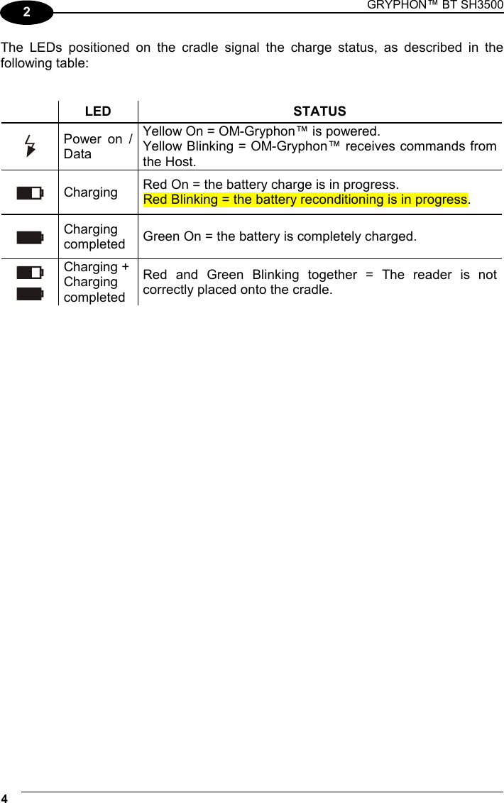
![Enter configuration ik ik USB Exit and Save Configuration i k i k 20 KEYBOARD NATIONALITY This parameter default value is restored through the Interface Selection code and not Restore Default. Belgian i'+Zk i'+Zk i'+Zk English French i'+Qk i'+Qk i'+Qk i'+Kk i'+Kk i'+Kk German Italian i'+Nk i'+Nk i'+Nk i'+Hk i'+Hk i'+Hk Spanish Swedish i'+Wk i'+Wk i'+Wk i'+Tk i'+Tk i'+Tk USA Japanese i'+Ek i'+Ek i'+Ek i'+]k i'+]k i'+]k](https://usermanual.wiki/Datalogic/0013/User-Guide-586715-Page-28.png)
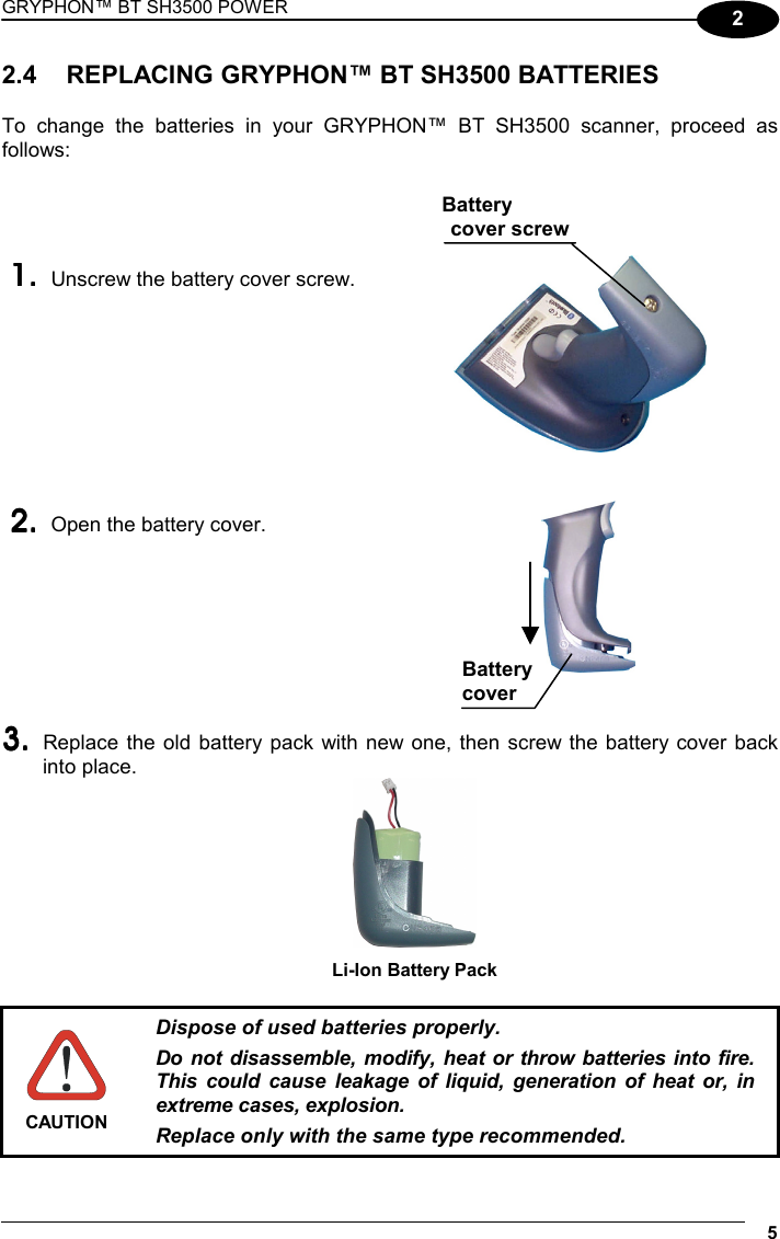
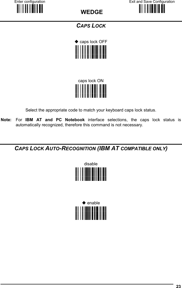
![Enter configuration ik ik WEDGE Exit and Save Configuration i k i k 22 KEYBOARD NATIONALITY Belgian i'+Zk i'+Zk i'+Zk English French i'+Qk i'+Qk i'+Qk i'+Kk i'+Kk i'+Kk German Italian i'+Nk i'+Nk i'+Nk i'+Hk i'+Hk i'+Hk Spanish Swedish i'+Wk i'+Wk i'+Wk i'+Tk i'+Tk i'+Tk USA i'+Ek i'+Ek i'+Ek The Japanese Keyboard Nationality selection is valid only for IBM AT compatible PCs. Japanese i'+]k i'+]k i'+]k](https://usermanual.wiki/Datalogic/0013/User-Guide-586715-Page-30.png)
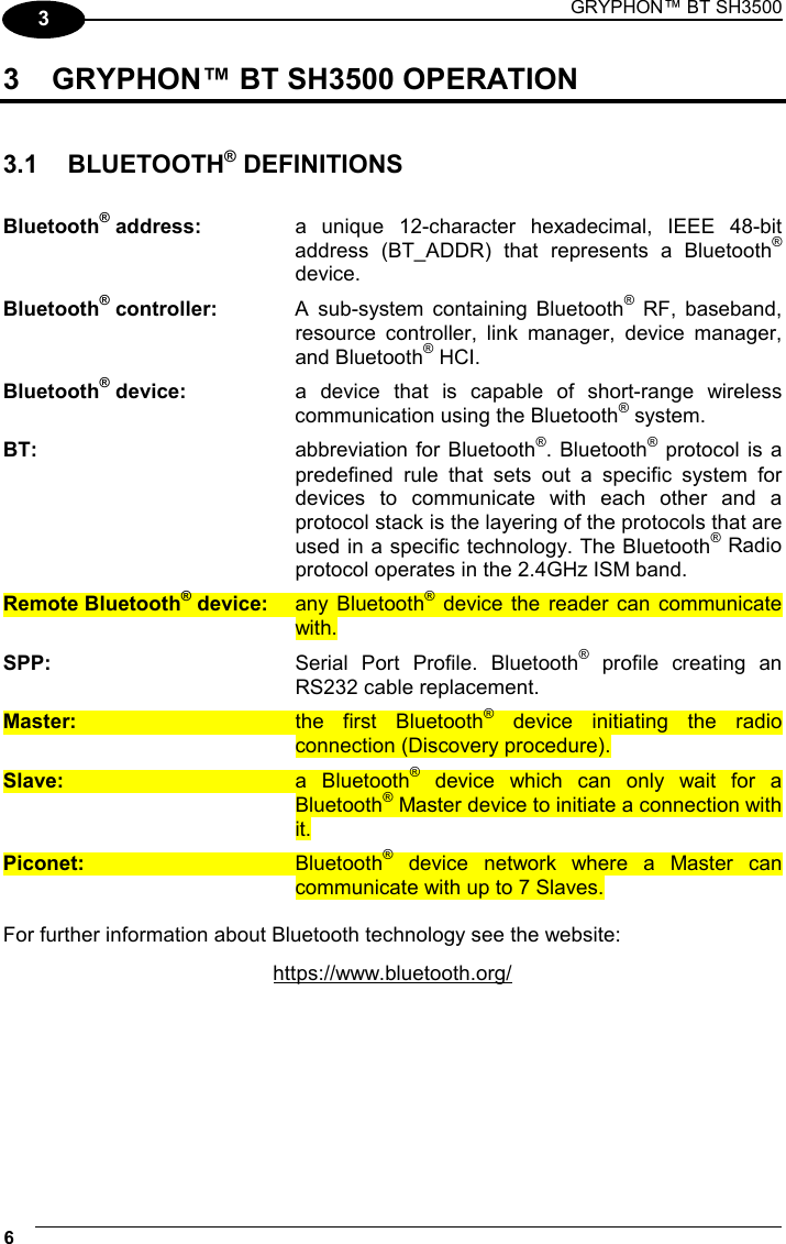
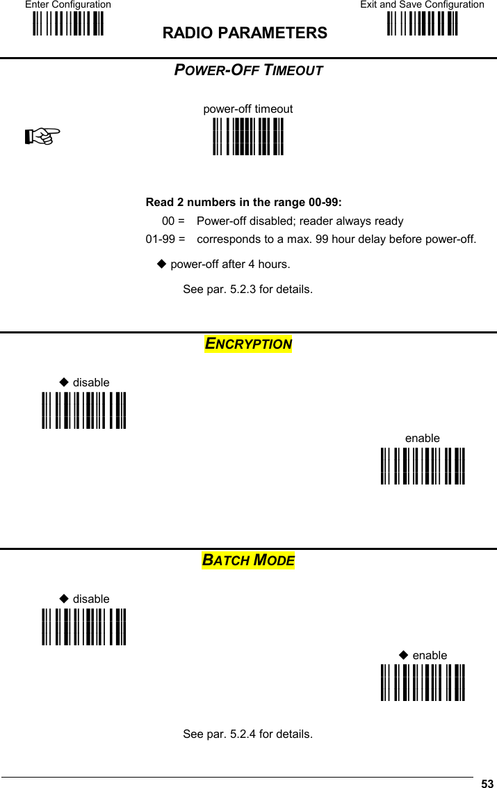
![Enter Configuration ik ik RADIO PARAMETERS Exit and Save Configuration i k i k 52 RADIO PROTOCOL TIMEOUT radio protocol timeout ☞ i3)k i3)k i3)k Read a number from the table where: 03-19 = timeout from 3 to 19 seconds 3 seconds See par. 5.2.1 for details. ACK/NACK PROTOCOL AND FRAME PACKING no ACK/NACK protocol nor frame packing i2-Tk i2-Tk i2-Tk ACK/NACK protocol only frame packing only i2-Wk i2-Wk i2-Wk i2-Zk i2-Zk i2-Zk ACK/NACK protocol and frame packing i2-]k i2-]k i2-]k See par. 5.2.2 for details.](https://usermanual.wiki/Datalogic/0013/User-Guide-586715-Page-60.png)
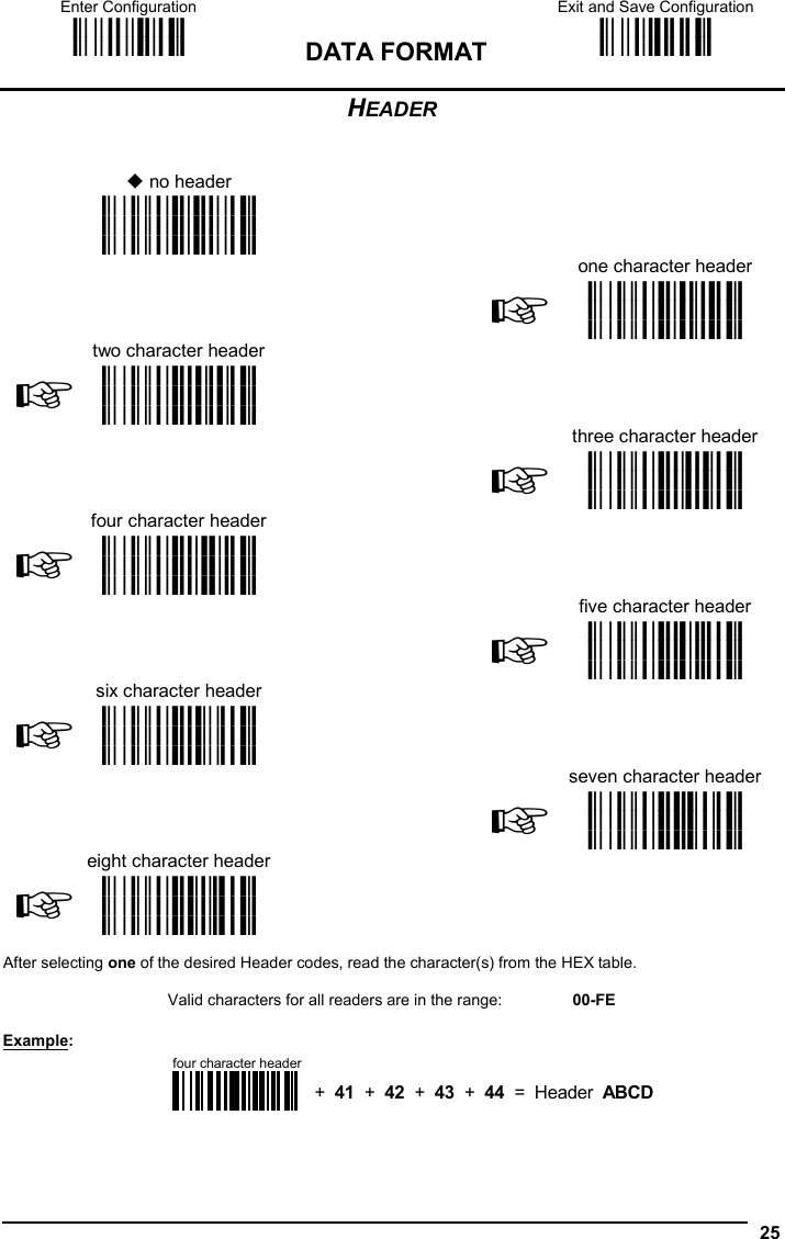
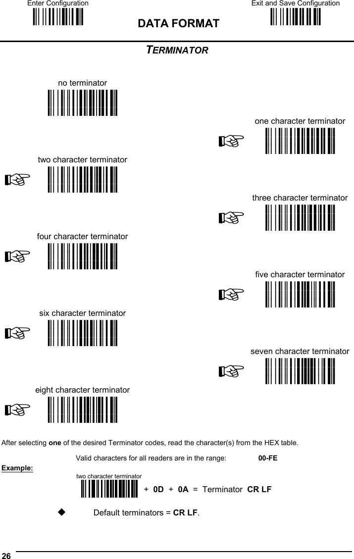
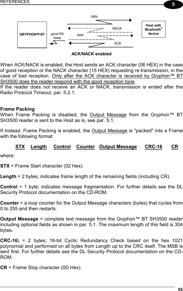
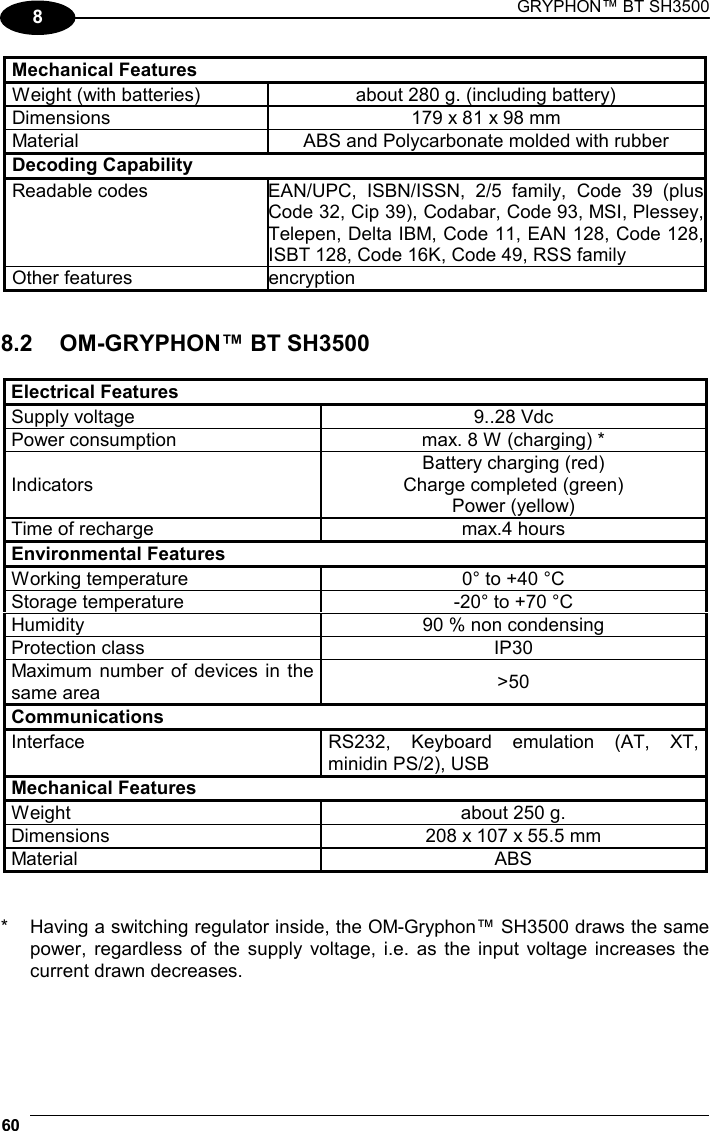
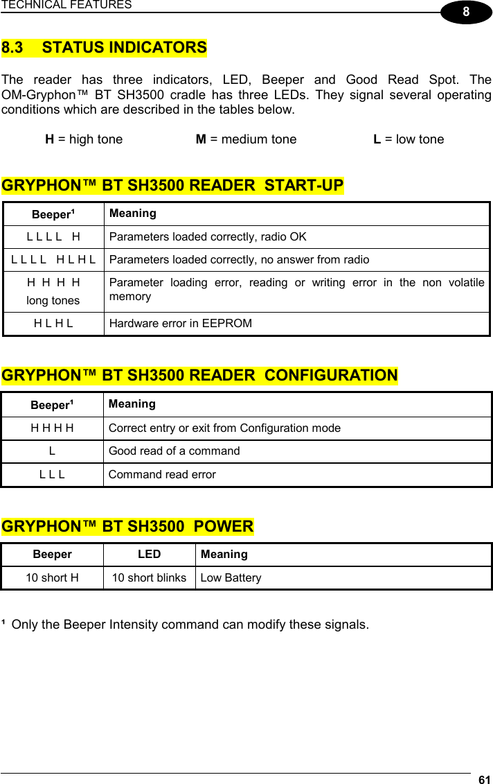
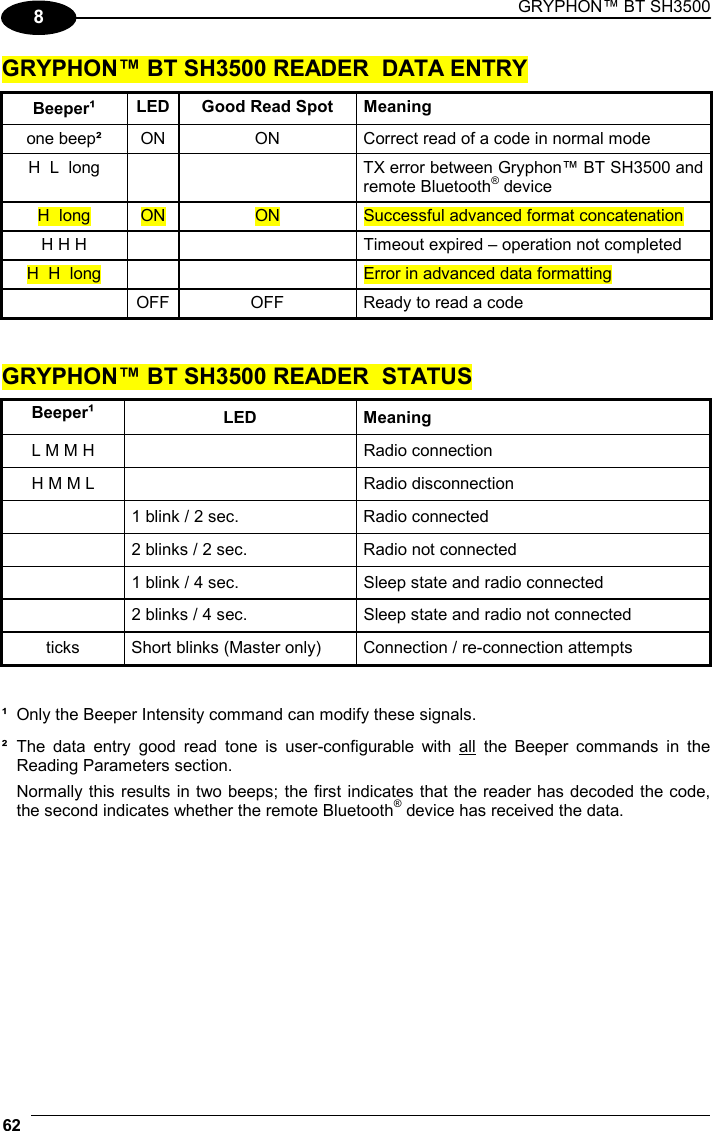
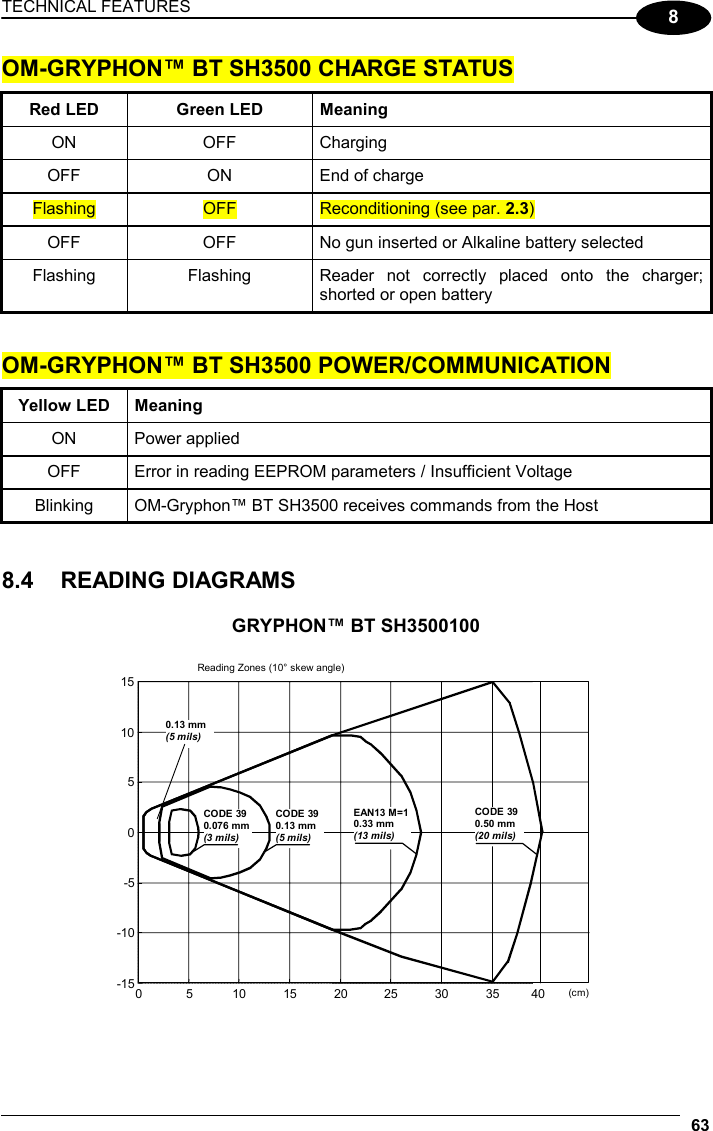
![GRYPHON™ BT SH3500 54 5 5 REFERENCES 5.1 DATA FORMAT The output message from Gryphon™ BT SH3500 towards the Host uses the following format: [Bluetooth Reader Addr] [Reader Addr Delimiter] [Header] [Code ID] [Code Length] CODE [Terminator] [Items in square brackets are optional.] 5.2 RADIO PARAMETERS 5.2.1 Radio Protocol Timeout This parameter sets the valid time to wait before transmission between the Gryphon™ BT SH3500 reader and the remote Bluetooth® device is considered failed. This parameter should be set taking into consideration the radio traffic (number of readers in the same area). It can be set between 3 and 19 seconds. 5.2.2 ACK/NACK Protocol and Frame Packing ACK/NACK Protocol The transmission protocol takes place between the reader and the Host. The reader passes its data (code read) to the remote Bluetooth® device (Host). When ACK/NACK is disabled, there is no control from reader to Host transmission, therefore the reader responds with the good reception tone. Host with Bluetooth® device GRYPHON BT data good RX beep ACK/NACK disabled](https://usermanual.wiki/Datalogic/0013/User-Guide-586715-Page-62.png)
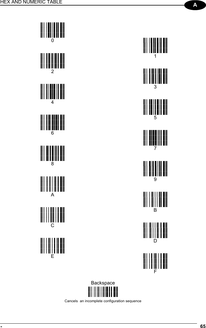
![GRYPHON™ BT SH3500 64 A A HEX AND NUMERIC TABLE CHARACTER TO HEX CONVERSION TABLE char hex char hex char hex NUL 00 * 2A U 55 SOH 01 + 2B V 56 STX 02 , 2C W 57 ETX 03 - 2D X 58 EOT 04 . 2E Y 59 ENQ 05 / 2F Z 5A ACK 06 0 30 [ 5B BEL 07 1 31 \ 5C BS 08 2 32 ] 5D HT 09 3 33 ^ 5E LF 0A 4 34 _ 5F VT 0B 5 35 ` 60 FF 0C 6 36 a 61 CR 0D 7 37 b 62 SO 0E 8 38 c 63 SI 0F 9 39 d 64 DLE 10 : 3A e 65 DC1 11 ; 3B f 66 DC2 12 < 3C g 67 DC3 13 = 3D h 68 DC4 14 > 3E i 69 NAK 15 ? 3F j 6A SYN 16 @ 40 k 6B ETB 17 A 41 l 6C CAN 18 B 42 m 6D EM 19 C 43 n 6E SUB 1A D 44 o 6F ESC 1B E 45 p 70 FS 1C F 46 q 71 GS 1D G 47 r 72 RS 1E H 48 s 73 US 1F I 49 t 74 SPACE 20 J 4A u 75 ! 21 K 4B v 76 " 22 L 4C w 77 # 23 M 4D x 78 $ 24 N 4E y 79 % 25 O 4F z 7A & 26 P 50 { 7B ' 27 Q 51 | 7C ( 28 R 52 } 7D ) 29 S 53 ~ 7E T 54 DEL 7F](https://usermanual.wiki/Datalogic/0013/User-Guide-586715-Page-72.png)