Datalogic 0014 GRYPHON BT - Barcode reader - GUN User Manual GryphonBT RM Master
Datalogic SpA GRYPHON BT - Barcode reader - GUN GryphonBT RM Master
Users Manual

GRYPHON™ BT SH3500
REFERENCE MANUAL

DATALOGIC S.p.A.
Via Candini 2
40012 - Lippo di Calderara di Reno
Bologna - Italy
GRYPHON™ BT SH3500
Ed.: 05/2005
This manual refers to software version 1.00 and later.
ALL RIGHTS RESERVED
Datalogic reserves the right to make modifications and improvements without prior notification.
Datalogic shall not be liable for technical or editorial errors or omissions contained herein, nor for incidental or
consequential damages resulting from the use of this material.
Product names mentioned herein are for identification purposes only and may be trademarks and or
registered trademarks of their respective companies.
© Datalogic S.p.A. 2000-2005
04/05/2005

iii
CONTENTS
GENERAL VIEW ......................................................................................... vi
COMPLIANCE............................................................................................ vii
LED CLASS............................................................................................... viii
1
INTRODUCTION .......................................................................................... 1
2
GRYPHON™ BT SH3500 POWER .............................................................. 2
2.1
Powering the OM-GRYPHON™ BT SH3500................................................ 2
2.2
Battery Type.................................................................................................. 3
2.3
Battery Charging........................................................................................... 3
2.4
Replacing Gryphon™ BT SH3500 Batteries ................................................. 5
3
GRYPHON™ BT SH3500 OPERATION ...................................................... 6
3.1
Bluetooth
®
Definitions ................................................................................... 6
3.2
Bluetooth
®
Radio Connection........................................................................ 7
3.3
OM-Gryphon™ BT SH3500 Cable Connections........................................... 8
3.4
RS232 Connection........................................................................................ 9
3.5
USB Connection ........................................................................................... 9
3.6
Wedge Connection ....................................................................................... 9
4
CONFIGURATION...................................................................................... 10
4.1
Configuration Method.................................................................................. 10
4.1.1
Reading Configuration Barcodes ................................................................ 10
4.2
Setup Procedure......................................................................................... 11
4.3
RS232 Interface Selection .......................................................................... 12
4.4
Wedge Interface Selection.......................................................................... 12
4.5
USB Interface Configuration and Selection................................................. 13
4.5.1
USB Interface Selection.............................................................................. 14
4.6
Changing Default Settings .......................................................................... 14
RS232 PARAMETERS............................................................................... 15
Baud Rate................................................................................................... 16
Parity........................................................................................................... 17
Data Bits ..................................................................................................... 17
Stop Bits...................................................................................................... 18
USB ............................................................................................................ 19
Keyboard Nationality................................................................................... 20
WEDGE PARAMETERS ............................................................................ 21
Keyboard Nationality................................................................................... 22

iv
Caps Lock................................................................................................... 23
Caps Lock Auto-Recognition (IBM AT compatible only) .............................. 23
DATA FORMAT.......................................................................................... 24
Header ........................................................................................................ 25
Terminator................................................................................................... 26
READING PARAMETERS ......................................................................... 27
Hand-Held Operation .................................................................................. 28
Flash Mode ................................................................................................. 28
Beeper Intensity.......................................................................................... 29
Beeper Tone ............................................................................................... 29
Beeper Type ............................................................................................... 30
Beeper Length ............................................................................................ 30
CODE SELECTION .................................................................................... 31
EAN/UPC Family ........................................................................................ 33
2/5 Family ................................................................................................... 37
Code 39 Family........................................................................................... 38
Code 128 Family......................................................................................... 40
Code 93 ...................................................................................................... 41
Codabar Family........................................................................................... 42
MSI.............................................................................................................. 44
Plessey ....................................................................................................... 45
Telepen....................................................................................................... 46
Delta IBM .................................................................................................... 47
Code 11 ...................................................................................................... 48
Code 16K.................................................................................................... 49
Code 49 ...................................................................................................... 49
RSS Family................................................................................................. 50
RADIO PARAMETERS .............................................................................. 51
Radio Protocol Timeout............................................................................... 52
ACK/NACK Protocol and Frame Packing.................................................... 52
Power-Off Timeout...................................................................................... 53
Encryption................................................................................................... 53
Batch Mode................................................................................................. 53
5
REFERENCES ........................................................................................... 54
5.1
Data Format................................................................................................ 54
5.2
Radio Parameters ....................................................................................... 54
5.2.1
Radio Protocol Timeout............................................................................... 54
5.2.2
ACK/NACK Protocol and Frame Packing.................................................... 54
5.2.3
Power-Off Timeout...................................................................................... 56
5.2.4
Batch Mode................................................................................................. 56
6
SYSTEM MANAGEMENT COMMANDS.................................................... 57

v
7
TROUBLESHOOTING................................................................................ 58
8
TECHNICAL FEATURES ........................................................................... 59
8.1
Gryphon™ BT SH3500 ............................................................................... 59
8.2
om-GRYPHON™ BT SH3500..................................................................... 60
8.3
Status Indicators ......................................................................................... 61
8.4
Reading Diagrams ...................................................................................... 63
A
HEX AND NUMERIC TABLE ..................................................................... 64
vi
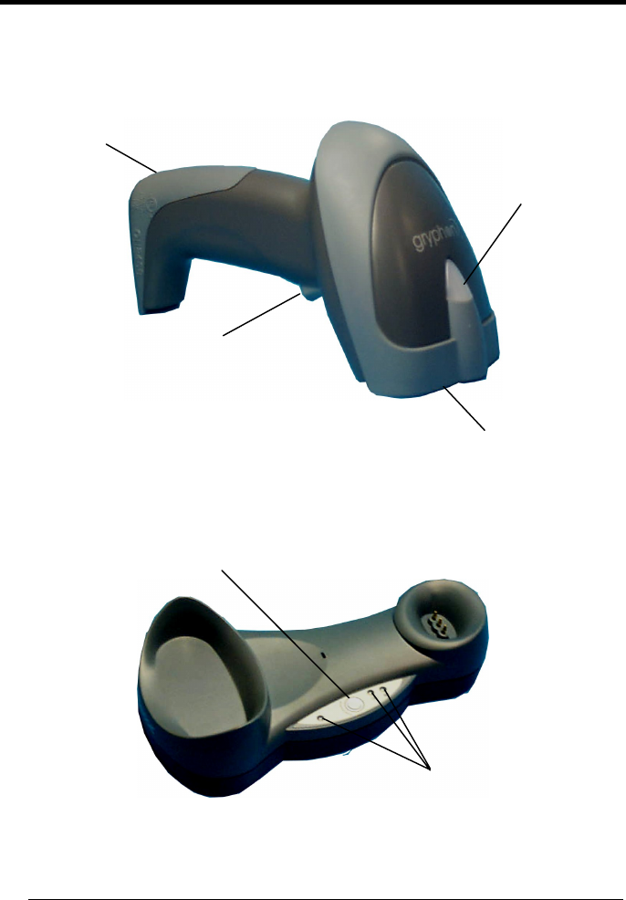
GENERAL VIEW
GRYPHON™ BT SH3500 READER
Figure A – Gryphon™ BT SH3500 Series Reader
Figure B – OM-Gryphon™ BT SH3500
Gun searcher
LEDs
Gryphon™ BT
SH3500
Battery Cover
Trigger
Blue LED
Reading window

vii
COMPLIANCE
This device must be opened by qualified personnel only.
The batteries must be removed before opening the device.
Modifications or changes to this equipment without the expressed
written approval of Datalogic could void the authority to use the
equipment.
This device complies with PART 15 of the FCC Rules. Operation is
subject to the following two conditions: (1) This device may not cause
harmful interference, and (2) this device must accept any interference
received, including interference which may cause undesired operation.
This equipment has been tested and found to comply with the limits for a Class B
digital device, pursuant to part 15 of the FCC Rules. These limits are designed to
provide reasonable protection against harmful interference in a residential
installation. This equipment generates, uses and can radiate radio frequency energy
and, if not installed and used in accordance with the instructions, may cause harmful
interference to radio communications. However, there is no guarantee that
interference will not occur in a particular installation. If this equipment does cause
harmful interference to radio or television reception, which can be determined by
turning the equipment off and on, the user is encouraged to try to correct the
interference by one or more of the following measures:
−
Reorient or relocate the receiving antenna.
−
Increase the separation between the equipment and receiver.
−
Connect the equipment into an outlet on a circuit different from that to which the
receiver is connected.
−
Consult the dealer or an experienced radio/TV technician for help.
Contact the competent authority responsible for the management of radio frequency
devices of your country to verify the eventual necessity of a user license.
Refer to the web site http://europa.eu.int/comm/enterprise/rtte/spectr.htm for further
information

viii
LED CLASS
TO EN60825-1:(2001)

INTRODUCTION
1
1
1 INTRODUCTION
Datalogic has moved a step ahead in the concept of “instinctive reading". The new
Gryphon™ BT SH3500 reader series has been developed to provide optimised
reading performance through excellent ergonomic design, a natural instinctive
reading approach and innovative good reading feedback.
The Gryphon™ BT SH3500 (Gryphon™ Bluetooth
®
) reader is a CCD wireless
barcode scanner communicating in the 2.4 GHz ISM band and using the Serial Port
Profile (SPP). Thanks to a Bluetooth
®
device, such as a Bluetooth
®
dongle, the
reader can send data to a remote Host such as a PC, PDA, printer, etc.
The “INSTINCTIVE READING DISTANCE,” a concept introduced by Datalogic a few
years ago based on in-depth ergonomic studies, represents the natural position of
the user while reading a code. The Gryphon™ BT SH3500 series takes this concept
one step further. It allows wireless operations at the desk/POS within a 10 meter
range. The new “blue spot,” (Datalogic patent application) produced by the
Gryphon™ BT SH3500 provides “good reading” feedback directly on the code, where
the user usually tends to be looking. Correct pointing becomes quick and easy
thanks to the sharp and bright illumination line. All these characteristics are coupled
with outstanding performance in terms of reading quickness and decoding capability
thanks to state-of-the-art optics and a decode rate of 270 scans/sec, making the
Gryphon™ BT SH3500 very user friendly, intuitive and fast.
Specially optimised optics allow reading of the most popular standard codes with
superior depths of field from near contact to over 30 cm. High resolution codes,
which can reach 3 mils are also easily read. The Gryphon™ BT SH3500 reader is
paving the road for innovative barcode reading.
The OM-Gryphon™ BT SH3500 cradle is provided in the package to build a Cordless
Reading System for the collection, decoding and transmission of barcoded data. It
can be connected to a Host PC through a USB, RS232 or Wedge emulation cable.
The OM-Gryphon™ BT SH3500 also allows charging the Gryphon™ BT SH3500
batteries.
GRYPHON™ BT SH3500
2
2
2 GRYPHON™ BT SH3500 POWER
To begin using your Gryphon™ BT SH3500 reader you must charge the
Gryphon™ BT SH3500 battery using OM-Gryphon™ BT SH3500 as described in
par. 2.3. A full charge takes less than 4 hours with Li-Ion batteries.
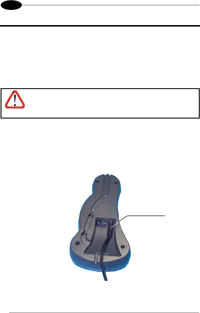
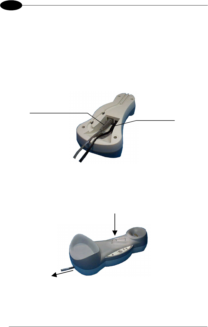
2.1 POWERING THE OM-GRYPHON™ BT SH3500
CAUTION
Connections should always be made with power off!
Apply power to OM-Gryphon™ BT SH3500 by connecting a power supply unit to the
connector on the base of the cradle.
OM-Gryphon™ BT SH3500 is ready to charge Gryphon™ BT SH3500 reader Li-Ion
batteries.
OM-Gryphon™ BT SH3500 Power Supply Connector
Power Supply
GRYPHON™ BT SH3500 POWER
3
2
2.2 BATTERY TYPE
You can install Li-Ion batteries in the Gryphon™ BT SH3500.
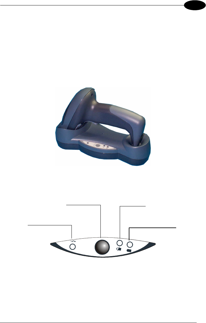
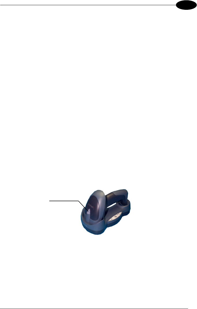
2.3 BATTERY CHARGING
Once the system is connected and powered, you can place the Gryphon™ BT
SH3500 onto the cradle to charge the battery.
Charging the Batteries
D
I
S
C
H
A
R
G
E
When the reader is correctly placed onto the cradle, the red LED on the cradle goes on
to indicate that the battery is charging. The green LED on the cradle goes on when the
battery is completely charged.
Power on / Data
(yellow LED)
Gun searcher
Charge completed
(green LED)
Charging
(
red LED
)

GRYPHON™ BT SH3500
4
2
The LEDs positioned on the cradle signal the charge status, as described in the
following table:
LED STATUS
Power on /
Data
Yellow On = OM-Gryphon™ is powered.
Yellow Blinking = OM-Gryphon™ receives commands from
the Host.
Charging Red On = the battery charge is in progress.
Red Blinking = the battery reconditioning is in progress.
Charging
completed Green On = the battery is completely charged.
Charging +
Charging
completed
Red and Green Blinking together = The reader is not
correctly placed onto the cradle.
GRYPHON™ BT SH3500 POWER
5
2
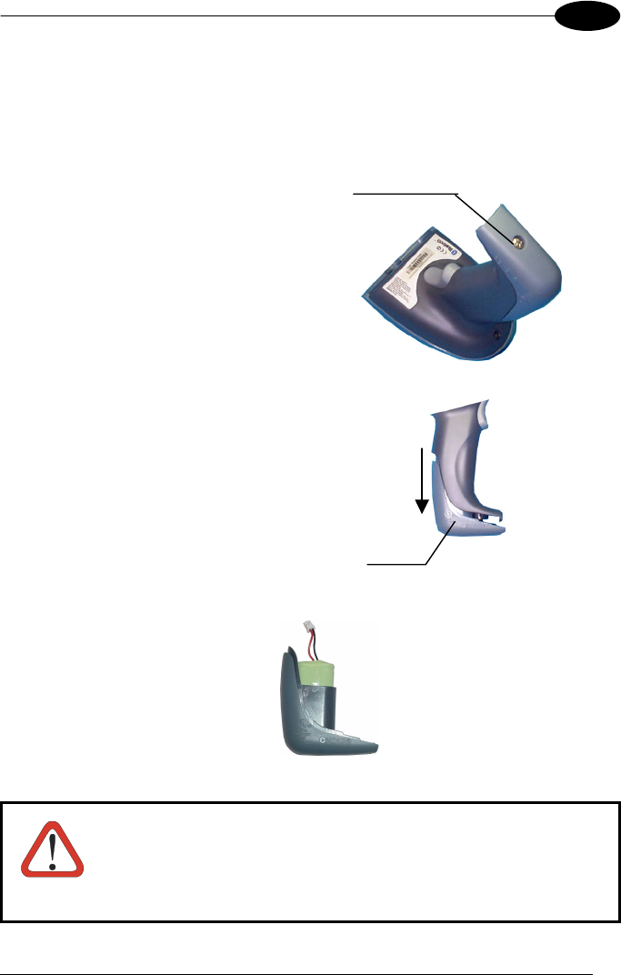
2.4 REPLACING GRYPHON™ BT SH3500 BATTERIES
To change the batteries in your GRYPHON™ BT SH3500 scanner, proceed as
follows:
1.
1.1.
1.
Unscrew the battery cover screw.
2.
2.2.
2.
Open the battery cover.
3.
3.3.
3.
Replace the old battery pack with new one, then screw the battery cover back
into place.
Li-Ion Battery Pack
CAUTION
Dispose of used batteries properly.
Do not disassemble, modify, heat or throw batteries into fire.
This could cause leakage of liquid, generation of heat or, in
extreme cases, explosion.
Replace only with the same type recommended.
Battery
cover
Batter
y
cover screw

GRYPHON™ BT SH3500
6
3
3 GRYPHON™ BT SH3500 OPERATION
3.1 BLUETOOTH
®
DEFINITIONS
Bluetooth
®
address: a unique 12-character hexadecimal, IEEE 48-bit
address (BT_ADDR) that represents a Bluetooth
®
device.
Bluetooth
®
controller: A sub-system containing Bluetooth
®
RF, baseband,
resource controller, link manager, device manager,
and Bluetooth
®
HCI.
Bluetooth
®
device: a device that is capable of short-range wireless
communication using the Bluetooth
®
system.
BT: abbreviation for Bluetooth
®
. Bluetooth
®
protocol is a
predefined rule that sets out a specific system for
devices to communicate with each other and a
protocol stack is the layering of the protocols that are
used in a specific technology. The Bluetooth
®
Radio
protocol operates in the 2.4GHz ISM band.
Remote Bluetooth
®
device: any Bluetooth
®
device the reader can communicate
with.
SPP: Serial Port Profile. Bluetooth
®
profile creating an
RS232 cable replacement.
Master: the first Bluetooth
®
device initiating the radio
connection (Discovery procedure).
Slave: a Bluetooth
®
device which can only wait for a
Bluetooth
®
Master device to initiate a connection with
it.
Piconet: Bluetooth
®
device network where a Master can
communicate with up to 7 Slaves.
For further information about Bluetooth technology see the website:
https://www.bluetooth.org/

GRYPHON™ BT SH3500 OPERATION
7
3
3.2 BLUETOOTH
®
RADIO CONNECTION
During typical operation a physical radio channel is shared by a group of devices that
are synchronized to a common clock and frequency hopping pattern. One device
provides the synchronization reference and is known as the Master. All other devices
are known as Slaves. A group of devices synchronized in this fashion form a piconet.
Most Bluetooth
®
devices can be both Master or Slave. The Master will be the first unit
to initiate the connection (page procedure).
Some devices can only be Slaves (i.e. printers). They can only wait for a Bluetooth
®
Master device to initiate a connection with them.
Gryphon™ BT SH3500 can be either Master or Slave. As Master it can initiate a
connection with only one Slave device.
The blue LED and / or the beeper always indicate the reader radio connection status
(see also the Reader Status table, at page 62):
• the radio connection is signaled by the blue LED through a single blink at regular
intervals, while if the reader radio is disconnected the LED emits two short blinks
at regular intervals;
• during the initialization procedure, if the radio connection attempt is successful,
the reader emits four ascending tones;
• the radio disconnection is signaled by four descending tones.
GRYPHON™ BT SH3500
8
3
3.3 OM-GRYPHON™ BT SH3500 CABLE CONNECTIONS
The OM-Gryphon™ BT SH3500 incorporates a multi-standard interface which can be
connected to a Host by simply plugging an RS232, USB or Wedge emulation cable
into the Host connector, placed on the base of the cradle. In addition the cradle must
be connected to an external power supply.
To connect the OM-Gryphon™ BT SH3500:
1. Connect the OM-Gryphon™ BT SH3500 to the appropriate interface cable which
must be simply plugged into the Host connector on the base of the cradle.
2. Connect the cradle to an external power supply, see the figure below.
Bottom View
To disconnect the cable, insert a paper clip or other similar object into the hole
corresponding to the Host connector on the body of the cradle. Push down on the clip
while unplugging the cable. Refer to the following figure:
Disconnecting the Cable
Host Interface Cable
Power Supply
GRYPHON™ BT SH3500 OPERATION
9
3
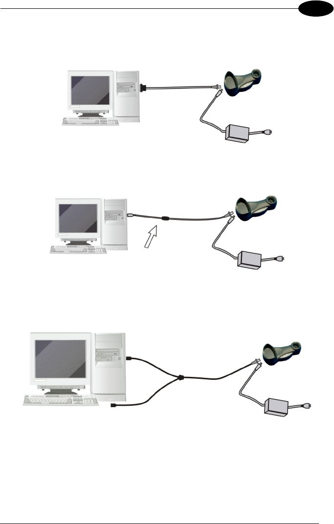
3.4 RS232 CONNECTION
3.5 USB CONNECTION
3.6 WEDGE CONNECTION
Host OM-Gryphon™ BT SH3500
RS232
Host OM-Gryphon™ BT SH3500
USB
Host
OM-Gryphon™ BT SH3500
WEDGE

GRYPHON™ BT SH3500
10
4
4 CONFIGURATION
4.1 CONFIGURATION METHOD
4.1.1 Reading Configuration Barcodes
This manual can be used for complete setup and configuration of your reader by
following the setup procedures in this chapter (see par. 4.2 for an overview).
If you wish to change the default settings, this manual provides complete
configuration of your reader in an easy way.
To configure your reader:
1)
Open the page of Appendix C with the hex-numeric table and keep it open
during the device configuration.
2)
Read the Enter Configuration code ONCE, available at the top of each page
of configuration.
3)
Modify the desired parameters in one or more sections following the
procedures given for each group.
4)
Read the Exit and Save Configuration code ONCE, available at the top of
each page of configuration.
Reference notes describing the operation of the more complex parameters are given
in chapter 5.
CONFIGURATION
11
4
4.2 SETUP PROCEDURE
Follow the given procedure to set up Gryphon™ BT SH3500.
Read the restore default parameters code below.
Restore Gryphon™ BT SH3500 Default
1.
iPk
iPk
iPk
Read the Bind code to pair the Gryphon™ BT SH3500 to the OM-Gryphon™
BT SH3500 cradle.
The reader is dedicated to the cradle. Any previously bound reader will be
excluded.
Bind
2.
i3/*k
i3/*k
i3/*k
The green LED on the Gryphon™ BT SH3500 will blink; the reader is ready to
be positioned onto the cradle.
Firmly position the reader onto the OM-Gryphon™ BT SH3500 cradle within
10 seconds, a beep will be emitted, signaling that the OM-Gryphon™ BT
SH3500 cradle has been paired to the Gryphon™ BT SH3500, and the green
LED on the reader will go off.
3.
YOUR READER IS NOW CONFIGURED TO READ BARCODES USING
THE DEFAULT VALUES.
4.
Configure the OM-Gryphon™ BT SH3500 cradle. Refer to par. 4.3, par. 4.4 or
par. 4.5 depending on the interface selection code required for your
application
Green LED

GRYPHON™ BT SH3500
12
4
4.3 RS232 INTERFACE SELECTION
1.
Read the OM-Gryphon™ BT SH3500 restore default code:
Restore OM-Gryphon™ BT SH3500 Default
i39Rk
i39Rk
i39Rk
2.
Read the RS232 interface selection code:
RS232
i$1k
i$1k
i$1k
4.4 WEDGE INTERFACE SELECTION
1.
Read the OM-Gryphon™ BT SH3500 restore default code:
Restore OM-Gryphon™ BT SH3500 Default
i39Rk
i39Rk
i39Rk
Read the interface selection code for your application:
WEDGE
IBM AT or PS/2 PCs
2.
i$1Bk
i$1Bk
i$1Bk
IBM XT
i$1Wk
i$1Wk
i$1Wk
CONFIGURATION
13
4
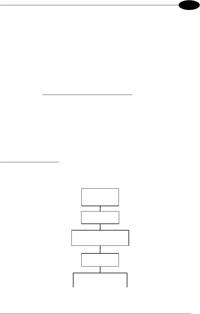
4.5 USB INTERFACE CONFIGURATION AND SELECTION
The USB interface is compatible with:
Windows 98 (and later) IBM POS for Windows
Mac OS 8.0 (and later) 4690 Operating System
USB START-UP
As with all USB devices, upon connection, the Host performs several checks by
communicating with the OM-Gryphon™ BT SH3500. Before the OM-Gryphon™ BT
SH3500 is ready, the correct USB driver must be loaded.
For all systems, the correct USB driver for the default USB-KBD interface is included
in the Host Operating System and will either be loaded automatically or will be
suggested by the O.S. and should therefore be selected from the dialog box (the first
time only).
You can now read codes with the associated Gryphon™ BT SH3500 reader. At this
point you can read the USB interface configuration code according to your
application. Load drivers from the O.S. (if requested). When configuring the USB-
COM interface, the relevant files and drivers must be installed from the USB Device
Installation software which can be downloaded from the web site:
http://www.datalogic.com.
The OM-Gryphon™ BT SH3500 is ready.
Connect OM-
Gryphon™ BT to
Host
Select desired USB interface
code (USB-KBD is default)
Read test codes.
OM-Gryphon™ BT is READY
Load drivers
(if requested)
Load drivers
(
if re
q
uested
)
First Start-Up
Successive start-ups will automatically recognize the previously loaded drivers.

GRYPHON™ BT SH3500
14
4
4.5.1 USB Interface Selection
USB
USB-KBD (default)
i6"k
i6"k
i6"k
USB-COM*
i6"k
i6"k
i6"k
* When configuring USB-COM, the relevant files and drivers must be installed from
the USB Device Installation software which can be downloaded from the web
page (see http://www.datalogic.com).
4.6 CHANGING DEFAULT SETTINGS
Once your reader is setup, you can change the default parameters to meet your
application needs. Refer to the preceding paragraphs for initial configuration in order
to set the default values and select the interface for your application.
In this manual, the configuration parameters are divided into logical groups making it
easy to find the desired function based on its reference group.
The first three groups are for Standard Interface parameter configuration:
•
RS232
•
USB
•
WEDGE
The following parameter groups are common to all interface applications:
DATA FORMAT parameters regard the messages sent to the Host system.
READING PARAMETERS control various operating modes and indicator status
functioning.
CODE SELECTION parameters allow configuration of a personalized mix of codes,
code families and their options.
RADIO PARAMETERS allow configuration of radio control parameters.

15
RS232 PARAMETERS
B
AUD
R
ATE
P
ARITY
D
ATA
B
ITS
S
TOP
B
ITS
1.
Read the Enter Configuration code ONCE, available at the top of each page.
2.
Read configuration codes from the desired groups.
☞
= Read the code and follow the procedure given
= Default value
3.
Read the Exit and Save Configuration code ONCE, available at the top of
each page.

Enter configuration
ik
ik
RS232
Exit and Save Configuration
i k
i k
16
B
AUD
R
ATE
150 baud
i$%6k
i$%6k
i$%6k
300 baud
600 baud
i$%9k
i$%9k
i$%9k
i$%<k
i$%<k
i$%<k
1200 baud
2400 baud
i$%?k
i$%?k
i$%?k
i$%Bk
i$%Bk
i$%Bk
4800 baud
9600 baud
i$%Ek
i$%Ek
i$%Ek
i$%Hk
i$%Hk
i$%Hk
19200 baud
38400 baud
i$%Kk
i$%Kk
i$%Kk
i$%Nk
i$%Nk
i$%Nk

Enter configuration
ik
ik
RS232
Exit and Save Configuration
i k
i k
17
P
ARITY
none
i$$4k
i$$4k
i$$4k
even parity
i$$7k
i$$7k
i$$7k
odd parity
i$$:k
i$$:k
i$$:k
D
ATA
B
ITS
7 bits
i$"0k
i$"0k
i$"0k
8 bits
i$"3k
i$"3k
i$"3k
9 bits
i$"6k
i$"6k
i$"6k

Enter configuration
ik
ik
RS232
Exit and Save Configuration
i k
i k
18
S
TOP
B
ITS
1 stop bit
i$#2k
i$#2k
i$#2k
2 stop bits
i$#5k
i$#5k
i$#5k

19
USB
USB-KBD
Keyboard nationality
1.
Read the Enter Configuration code ONCE, available at the top of each page.
2.
Read configuration codes from the desired groups.
☞
= Read the code and follow the procedure given
= Default value
3.
Read the Exit and Save Configuration code ONCE, available at the top of
each page.

Enter configuration
ik
ik
USB
Exit and Save Configuration
i k
i k
20
K
EYBOARD
N
ATIONALITY
This parameter default value is restored through the Interface Selection code and not
Restore Default.
Belgian
i'+Zk
i'+Zk
i'+Zk
English
French
i'+Qk
i'+Qk
i'+Qk
i'+Kk
i'+Kk
i'+Kk
German
Italian
i'+Nk
i'+Nk
i'+Nk
i'+Hk
i'+Hk
i'+Hk
Spanish
Swedish
i'+Wk
i'+Wk
i'+Wk
i'+Tk
i'+Tk
i'+Tk
USA
Japanese
i'+Ek
i'+Ek
i'+Ek
i'+]k
i'+]k
i'+]k

21
WEDGE PARAMETERS
K
EYBOARD
N
ATIONALITY
C
APS
L
OCK
C
APS
L
OCK
A
UTO
-
RECOGNITION
1.
Read the Enter Configuration code ONCE, available at the top of each page.
2.
Read configuration codes from the desired groups.
☞
= Read the code and follow the procedure given
= Default value
3.
Read the Exit and Save Configuration code ONCE, available at the top of
each page.

Enter configuration
ik
ik
WEDGE
Exit and Save Configuration
i k
i k
22
K
EYBOARD
N
ATIONALITY
Belgian
i'+Zk
i'+Zk
i'+Zk
English
French
i'+Qk
i'+Qk
i'+Qk
i'+Kk
i'+Kk
i'+Kk
German
Italian
i'+Nk
i'+Nk
i'+Nk
i'+Hk
i'+Hk
i'+Hk
Spanish
Swedish
i'+Wk
i'+Wk
i'+Wk
i'+Tk
i'+Tk
i'+Tk
USA
i'+Ek
i'+Ek
i'+Ek
The Japanese Keyboard Nationality selection is valid only for IBM AT compatible PCs.
Japanese
i'+]k
i'+]k
i'+]k

Enter configuration
ik
ik
WEDGE
Exit and Save Configuration
i k
i k
23
C
APS
L
OCK
caps lock OFF
i'&;k
i'&;k
i'&;k
caps lock ON
i'&>k
i'&>k
i'&>k
Select the appropriate code to match your keyboard caps lock status.
Note: For IBM AT and PC Notebook interface selections, the caps lock status is
automatically recognized, therefore this command is not necessary.
C
APS
L
OCK
A
UTO
-R
ECOGNITION
(IBM AT
COMPATIBLE ONLY
)
disable
i'1Qk
i'1Qk
i'1Qk
enable
i'1Tk
i'1Tk
i'1Tk

24
DATA FORMAT
H
EADER
T
ERMINATOR
1.
Read the Enter Configuration code ONCE, available at the top of each page.
2.
Read configuration codes from the desired groups.
☞
= Read the code and follow the procedure given
= Default value
3.
Read the Exit and Save Configuration code ONCE, available at the top of
each page.

Enter Configuration
ik
ik
DATA FORMAT
Exit and Save Configuration
i k
i k
25
H
EADER
no header
i&"k
i&"k
i&"k
one character header
two character header
☞
i&"k
i&"k
i&"k
☞
i&"k
i&"k
i&"k
three character header
four character header
☞
i&"k
i&"k
i&"k
☞
i&"k
i&"k
i&"k
five character header
six character header
☞
i&"k
i&"k
i&"k
☞
i&"#k
i&"#k
i&"#k
seven character header
eight character header
☞
i&"'k
i&"'k
i&"'k
☞
i&"+k
i&"+k
i&"+k
After selecting one of the desired Header codes, read the character(s) from the HEX table.
Valid characters for all readers are in the range: 00-FE
Example:
four character header
+ 41 + 42 + 43 + 44 = Header ABCD

Enter Configuration
ik
ik
DATA FORMAT
Exit and Save Configuration
i k
i k
26
T
ERMINATOR
no terminator
i&"k
i&"k
i&"k
one character terminator
two character terminator
☞
i&"k
i&"k
i&"k
☞
i&"k
i&"k
i&"k
three character terminator
four character terminator
☞
i&"k
i&"k
i&"k
☞
i&"k
i&"k
i&"k
five character terminator
six character terminator
☞
i&""k
i&""k
i&""k
☞
i&"&k
i&"&k
i&"&k
seven character terminator
eight character terminator
☞
i&"*k
i&"*k
i&"*k
☞
i&".k
i&".k
i&".k
After selecting one of the desired Terminator codes, read the character(s) from the HEX table.
Valid characters for all readers are in the range: 00-FE
Example:
two character terminator
+ 0D + 0A = Terminator CR LF
Default terminators = CR LF.

27
READING PARAMETERS
H
AND
-H
ELD
O
PERATION
F
LASH
M
ODE
B
EEPER
I
NTENSITY
B
EEPER
T
ONE
B
EEPER
T
YPE
B
EEPER
L
ENGTH
1.
Read the Enter Configuration code ONCE, available at the top of each page.
2.
Read configuration codes from the desired groups.
☞
= Read the code and follow the procedure given
= Default value
3.
Read the Exit and Save Configuration code ONCE, available at the top of
each page.

Enter Configuration
ik
ik
READING PARAMETERS
Exit and Save Configuration
i k
i k
28
H
AND
-H
ELD
O
PERATION
hardware trigger
i#,Fk
i#,Fk
i#,Fk
software trigger
i#,Ck
i#,Ck
i#,Ck
F
LASH
M
ODE
"FLASH" ON duration
☞
i##1k
i##1k
i##1k
"FLASH" OFF duration
☞
i##4k
i##4k
i##4k
Read 2 numbers in the range 01-99:
01 to 99 = from .1 to 9.9 seconds.
Flash-ON = 1 sec. Flash-OFF = 0.6 sec

Enter Configuration
ik
ik
READING PARAMETERS
Exit and Save Configuration
i k
i k
29
B
EEPER
I
NTENSITY
* very low intensity
i#(;k
i#(;k
i#(;k
low intensity
medium intensity
i#(>k
i#(>k
i#(>k
i#(Ak
i#(Ak
i#(Ak
high intensity
i#(Dk
i#(Dk
i#(Dk
* This sets the beeper OFF for data entry, while for all other beeper signals it has the
meaning very low intensity.
The Intensity parameter is effective for all operating conditions described in par. 8.3.
B
EEPER
T
ONE
tone 1
i#)=k
i#)=k
i#)=k
tone 2
tone 3
i#)@k
i#)@k
i#)@k
i#)Ck
i#)Ck
i#)Ck
tone 4
i#)Fk
i#)Fk
i#)Fk

Enter Configuration
ik
ik
READING PARAMETERS
Exit and Save Configuration
i k
i k
30
B
EEPER
T
YPE
monotone
i#+Ak
i#+Ak
i#+Ak
bitonal
i#+Dk
i#+Dk
i#+Dk
B
EEPER
L
ENGTH
long
i#*?k
i#*?k
i#*?k
short
i#*Bk
i#*Bk
i#*Bk

31
CODE SELECTION
EAN/UPC F
AMILY
2/5
FAMILY
C
ODE
39 F
AMILY
C
ODE
128 F
AMILY
C
ODABAR
F
AMILY
C
ODE
93
MSI
P
LESSEY
T
ELEPEN
D
ELTA
IBM
C
ODE
11
C
ODE
16K
C
ODE
49
RSS F
AMILY
1.
Read the Enter Configuration code ONCE, available at the top of each page.
2.
Read configuration codes from the desired groups.
☞
= Read the code and follow the procedure given
= Default value
3.
Read the Exit and Save Configuration code ONCE, available at the top of
each page.
Enter Configuration
ik
ik
CODE SELECTION
Exit and Save Configuration
i k
i k
32
DISABLE ALL CODE FAMILIES
i";`k
i";`k
i";`k
NOTE
The reader allows up to 5 code selections. This does not limit the
number of CODES enabled to 5, as it depends on the code family.
SINGLE
SELECTIONS =
Example
5 code selections: 1. 2/5 Interleaved
2. 2/5 Industrial
3. Code 128 + EAN 128
4. Code 39 Full ASCII + Code 32
5. UPC A/UPC E
In this section all SINGLE code selections are underlined and in bold.
• ONE combination code from the EAN family
• ONE code from the 2/5 family

Enter Configuration
ik
ik
CODE SELECTION
Exit and Save Configuration
i k
i k
33
EAN/UPC F
AMILY
disable the family
i"".k
i"".k
i"".k
Read the desired family code
Note:
Since the EAN/UPC without ADD ON code selection is enabled by default, to correctly enable
another selection, first disable the family.
EAN 8/EAN 13/UPC A/UPC E with and without ADD ON
i""Fk
i""Fk
i""Fk
WITHOUT ADD ON
EAN 8/EAN 13/UPC A/UPC E
i""1k
i""1k
i""1k
EAN 8/EAN 13
i""7k
i""7k
i""7k
UPC A/UPC E
i"":k
i"":k
i"":k

Enter Configuration
ik
ik
CODE SELECTION
Exit and Save Configuration
i k
i k
34
WITH ADD ON 2 AND 5
EAN 8/EAN 13/UPC A/UPC E
i""=k
i""=k
i""=k
EAN 8/EAN 13
i""@k
i""@k
i""@k
UPC A/UPC E
i""Ck
i""Ck
i""Ck
WITH ADD ON 2 ONLY
EAN 8/EAN 13
i"",k
i"",k
i"",k
UPC A/UPC E
i"".k
i"".k
i"".k
WITH ADD ON 5 ONLY
EAN 8/EAN 13
i""-k
i""-k
i""-k
UPC A/UPC E
i""/!k
i""/!k
i""/!k

Enter Configuration
ik
ik
CODE SELECTION
Exit and Save Configuration
i k
i k
35
EAN/UPC CHECK DIGIT TX SELECTIONS
For each code type in this family you can choose to transmit the check digit or not
CHECK DIGIT
TRANSMISSION
EAN 8
NO CHECK DIGIT
TRANSMISSION
i""(Pk
i""(Pk
i""(Pk
EAN 8
i""(Lk
i""(Lk
i""(Lk
EAN 13
i"")Sk
i"")Sk
i"")Sk
EAN 13
i"")Ok
i"")Ok
i"")Ok
UPC A
i""*Vk
i""*Vk
i""*Vk
UPC A
i""*Rk
i""*Rk
i""*Rk
UPC E
i""+Yk
i""+Yk
i""+Yk
UPC E
i""+Uk
i""+Uk
i""+Uk

Enter Configuration
ik
ik
CODE SELECTION
Exit and Save Configuration
i k
i k
36
CONVERSION OPTIONS
UPC E to UPC A conversion
i"""ak
i"""ak
i"""ak
UPC E to EAN 13 conversion
i""#dk
i""#dk
i""#dk
UPC A to EAN 13 conversion
i""$gk
i""$gk
i""$gk
EAN 8 to EAN 13 conversion
i""%k
i""%k
i""%k
enable only ISBN conversion
i"1Ok
i"1Ok
i"1Ok
enable only ISSN conversion
i"1Rk
i"1Rk
i"1Rk
enable both ISBN and ISSN conversion
i"1Uk
i"1Uk
i"1Uk
disable both ISBN and ISSN conversion
i"1Lk
i"1Lk
i"1Lk

Enter Configuration
ik
ik
CODE SELECTION
Exit and Save Configuration
i k
i k
37
2/5 F
AMILY
disable the family
i"$2k
i"$2k
i"$2k
Read the desired family code
Read a check digit selection
Interleaved 2/5
☞
i"$5k
i"$5k
i"$5k
CHECK DIGIT TABLE
no check digit control
Normal 2/5 (5 Bars)
ik
ik
ik
☞
i"$8k
i"$8k
i"$8k
check digit control and transmission
Industrial 2/5 (IATA)
ik
ik
ik
☞
i"$;k
i"$;k
i"$;k
Check digit control without transmission
Matrix 2/5 (3 Bars)
ik
ik
ik
☞
i"$>k
i"$>k
i"$>k
Read 4 numbers for the code length
where:
− First 2 digits = minimum code
length.
− Second 2 digits = maximum code
length.
The pharmaceutical code below is part of
the 2/5 family but has no check digit nor
code length selections.
Code CIP/HR
The maximum code length is 99
characters.
The minimum code length must always
be less than or equal to the maximum.
Examples:
i"$Ak
i"$Ak
i"$Ak
French pharmaceutical code
0199 = variable from 1 to 99 digits in
the code.
1010 = 10 digit code length only.

Enter Configuration
ik
ik
CODE SELECTION
Exit and Save Configuration
i k
i k
38
C
ODE
39 F
AMILY
disable the family
i"#0k
i"#0k
i"#0k
Read the desired family code
Read a check digit selection
Standard Code 39
CHECK DIGIT TABLE
no check digit control
☞
i"#3k
i"#3k
i"#3k
ik
ik
ik
Full ASCII Code 39
check digit control
and transmission
☞
i"#6k
i"#6k
i"#6k
ik
ik
ik
check digit control
without transmission
ik
ik
ik

Enter Configuration
ik
ik
CODE SELECTION
Exit and Save Configuration
i k
i k
39
The pharmaceutical codes below are part of the Code 39 family but have no check digit
selections.
Code CIP39
i"#9k
i"#9k
i"#9k
French pharmaceutical code
Code 32
i"#<k
i"#<k
i"#<k
Italian pharmaceutical code
CODE LENGTH (optional)
The code length selection is valid for the entire Code 39 family
Read the code + 4 numbers for the code length where: set code length
First 2 digits = minimum code length.
Second 2 digits = maximum code length.
i"#k
i"#k
i"#k
The maximum code length is 99 characters. The minimum code length must always be less
than or equal to the maximum.
Examples: 0199 = variable from 1 to 99 digits in the code. 1010 = 10 digit code length only.

Enter Configuration
ik
ik
CODE SELECTION
Exit and Save Configuration
i k
i k
40
C
ODE
128 F
AMILY
disable the family
i"*>k
i"*>k
i"*>k
Read the desired family code
Code 128
i"*k
i"*k
i"*k
control without transmission
of check digit
EAN 128
i"*!k
i"*!k
i"*!k
control without transmission
of check digit
Add GS Before Code
Code EAN 128 uses the ASCII <GS> character to separate a variable length code field from the
next code field. This character can also be added before the code.
disable
i&2Rk
i&2Rk
i&2Rk
enable
i&2Uk
i&2Uk
i&2Uk

Enter Configuration
ik
ik
CODE SELECTION
Exit and Save Configuration
i k
i k
41
ISBT 128
i"*$k
i"*$k
i"*$k
Enabling ISBT 128 automatically disables Puzzle Solver.
CODE LENGTH (optional)
The code length selection is valid for the entire Code 128 family
Read the code + 4 numbers for the code length where: set code length
First 2 digits = minimum code length.
Second 2 digits = maximum code length.
i"*-+k
i"*-+k
i"*-+k
The maximum code length is 99 characters. The minimum code length must always be less
than or equal to the maximum.
Examples: 0199 = variable from 1 to 99 digits in the code. 1010 = 10 digit code length only.
The length is calculated on the output string.
C
ODE
93
disable the code
i",Bk
i",Bk
i",Bk
Code 93
i",Ek
i",Ek
i",Ek
control without transmission
of check digit

Enter Configuration
ik
ik
CODE SELECTION
Exit and Save Configuration
i k
i k
42
C
ODABAR
F
AMILY
disable the family
i"%4k
i"%4k
i"%4k
Read the desired equality control code
Read a start/stop transmission
selection
START/STOP CHARACTER
TRANSMISSION
Standard Codabar
☞
i"%k
i"%k
i"%k
no start/stop character equality control
no transmission
ik
ik
ik
Standard Codabar
☞
i"%k
i"%k
i"%k
start/stop character equality control
transmission
ik
ik
ik
The Codabar ABC code below uses a fixed start/stop character transmission selection.
Codabar ABC
i"%k
i"%k
i"%k
no start/stop character equality control but transmission.

Enter Configuration
ik
ik
CODE SELECTION
Exit and Save Configuration
i k
i k
43
Codabar ABC Forced Concatenation
enable Codabar ABC with forced concatenation
i"%k
i"%k
i"%k
non start/stop character equality control but transmission
CODE LENGTH (optional)
The code length selection is valid for the entire Codabar family
Read the code + 4 numbers for the code length where: set code length
First 2 digits = minimum code length.
Second 2 digits = maximum code length.
i"%"k
i"%"k
i"%"k
The maximum code length is 99 characters. The minimum code length must always be less
than or equal to the maximum.
Examples: 0199 = variable from 1 to 99 digits in the code. 1010 = 10 digit code length only.
START/STOP CHARACTER CASE IN TRANSMISSION
The start/stop character case selections below are valid for the entire Codabar family:
transmit start/stop characters in lower case
i"%"@k
i"%"@k
i"%"@k
transmit start/stop characters in upper case
i"%"Dk
i"%"Dk
i"%"Dk

Enter Configuration
ik
ik
CODE SELECTION
Exit and Save Configuration
i k
i k
44
MSI
disable the family
i"&6k
i"&6k
i"&6k
Enable the code by selecting one of the check digit selections.
no check digit control
i"&9k
i"&9k
i"&9k
MOD10 check digit control
no check digit transmission
i"&<k
i"&<k
i"&<k
MOD10 check digit control
check digit transmission
i"&?k
i"&?k
i"&?k
MOD11 - MOD10 check digit control
no check digit transmission
i"&Bk
i"&Bk
i"&Bk
MOD11 - MOD10 check digit control
check digit transmission
i"&Ek
i"&Ek
i"&Ek
MOD10 - MOD10 check digit control
no check digit transmission
i"&Hk
i"&Hk
i"&Hk
MOD10 - MOD10 check digit control
check digit transmission
i"&Kk
i"&Kk
i"&Kk

Enter Configuration
ik
ik
CODE SELECTION
Exit and Save Configuration
i k
i k
45
P
LESSEY
disable the family
i"'8k
i"'8k
i"'8k
Enable the code by selecting one of the check digit selections.
Standard Plessey
no check digit control
i"'k
i"'k
i"'k
check digit control
check digit transmitted
i"'k
i"'k
i"'k
check digit control
check digit not transmitted
i"' k
i"' k
i"' k
Anker Plessey
no check digit control
i"'k
i"'k
i"'k
check digit control
check digit transmitted
i"'k
i"'k
i"'k
check digit control
check digit not transmitted
i"'#k
i"'#k
i"'#k

Enter Configuration
ik
ik
CODE SELECTION
Exit and Save Configuration
i k
i k
46
T
ELEPEN
disable the family
i"-Dk
i"-Dk
i"-Dk
Enable the code by selecting one of the check digit selections.
Numeric Telepen
no check digit control
i"-$k
i"-$k
i"-$k
check digit control
check digit transmitted
i"-(k
i"-(k
i"-(k
check digit control
check digit not transmitted
i"-,k
i"-,k
i"-,k
Alphanumeric Telepen
no check digit control
i"-'k
i"-'k
i"-'k
check digit control
check digit transmitted
i"-+k
i"-+k
i"-+k
check digit control
check digit not transmitted
i"-/k
i"-/k
i"-/k

Enter Configuration
ik
ik
CODE SELECTION
Exit and Save Configuration
i k
i k
47
D
ELTA
IBM
disable the family
i")<k
i")<k
i")<k
Enable the code by selecting one of the check digit selections.
no check digit control
i")?k
i")?k
i")?k
Type 1 check digit control
i")Bk
i")Bk
i")Bk
Type 2 check digit control
i")Ek
i")Ek
i")Ek

Enter Configuration
ik
ik
CODE SELECTION
Exit and Save Configuration
i k
i k
48
C
ODE
11
disable the family
i"(:k
i"(:k
i"(:k
Enable the code by selecting one of the check digit selections.
no check digit control
i"(=k
i"(=k
i"(=k
Type C check digit control
check digit transmitted
i"(k
i"(k
i"(k
Type C check digit control
check digit not transmitted
i"(!k
i"(!k
i"(!k
Type K check digit control
check digit transmitted
i"( k
i"( k
i"( k
Type K check digit control
check digit not transmitted
i"($k
i"($k
i"($k
Type C and Type K
check digit control
check digits transmitted
i"(#k
i"(#k
i"(#k
Type C and Type K
check digit control
check digits not transmitted
i"('k
i"('k
i"('k

Enter Configuration
ik
ik
CODE SELECTION
Exit and Save Configuration
i k
i k
49
C
ODE
16K
disable the code
i"+@k
i"+@k
i"+@k
Code 16K
i"+Ck
i"+Ck
i"+Ck
To read stacked codes, simply move the illuminated bar over the code so that each line of the
code is scanned. During this process a series of brief "ticks" indicates that reading is proceeding
correctly.
C
ODE
49
disable the code
i".Fk
i".Fk
i".Fk
Code 49
i".Ik
i".Ik
i".Ik
To read stacked codes, simply move the illuminated bar over the code so that each line of the
code is scanned. During this process a series of brief "ticks" indicates that reading is proceeding
correctly.

Enter Configuration
ik
ik
CODE SELECTION
Exit and Save Configuration
i k
i k
50
RSS F
AMILY
disables the family
i"2Nk
i"2Nk
i"2Nk
DISABLE CODE
ENABLE CODE
disable RSS Expanded Linear
and Stacked
i"2*k
i"2*k
i"2*k
enable RSS Expanded Linear
and Stacked
i"2.k
i"2.k
i"2.k
disable RSS Limited
i"2-k
i"2-k
i"2-k
enable RSS Limited
i"21k
i"21k
i"21k
disable RSS 14 Linear and
Stacked
i"20k
i"20k
i"20k
enable RSS 14 Linear and
Stacked
i"24k
i"24k
i"24k
To read the stacked version of these codes, simply move the reader over the code so that each
line of the code is scanned.

51
RADIO PARAMETERS
R
ADIO
P
ROTOCOL
T
IMEOUT
ACK/NACK P
ROTOCOL AND
F
RAME
P
ACKING
P
OWER
-O
FF
T
IMEOUT
E
NCRYPTION
B
ATCH
M
ODE
1.
Read the Enter Configuration code ONCE, available at the top of each page.
2.
Read configuration codes from the desired groups.
☞
= Read the code and follow the procedure given
3.
Read the Exit and Save Configuration code ONCE, available at the top of
each page.

Enter Configuration
ik
ik
RADIO PARAMETERS
Exit and Save Configuration
i k
i k
52
R
ADIO
P
ROTOCOL
T
IMEOUT
radio protocol timeout
☞
i3)k
i3)k
i3)k
Read a number from the table where:
03-19 = timeout from 3 to 19 seconds
3 seconds
See par. 5.2.1 for details.
ACK/NACK P
ROTOCOL AND
F
RAME
P
ACKING
no ACK/NACK protocol
nor frame packing
i2-Tk
i2-Tk
i2-Tk
ACK/NACK protocol only
frame packing only
i2-Wk
i2-Wk
i2-Wk
i2-Zk
i2-Zk
i2-Zk
ACK/NACK protocol
and frame packing
i2-]k
i2-]k
i2-]k
See par. 5.2.2 for details.

Enter Configuration
ik
ik
RADIO PARAMETERS
Exit and Save Configuration
i k
i k
53
P
OWER
-O
FF
T
IMEOUT
power-off timeout
☞
i31-k
i31-k
i31-k
Read 2 numbers in the range 00-99:
00 = Power-off disabled; reader always ready
01-99 = corresponds to a max. 99 hour delay before power-off.
power-off after 4 hours.
See par. 5.2.3 for details.
E
NCRYPTION
disable
i2#@k
i2#@k
i2#@k
enable
i2#Ck
i2#Ck
i2#Ck
B
ATCH
M
ODE
disable
i2&Fk
i2&Fk
i2&Fk
enable
i2&Ik
i2&Ik
i2&Ik
See par. 5.2.4 for details.

GRYPHON™ BT SH3500
54
5
5 REFERENCES
5.1 DATA FORMAT
The output message from Gryphon™ BT SH3500 towards the Host uses the
following format:
[Bluetooth
Reader Addr] [Reader Addr Delimiter] [Header]
[Code ID] [Code Length]
CODE
[Terminator]
[Items in square brackets are optional.]
5.2 RADIO PARAMETERS
5.2.1 Radio Protocol Timeout
This parameter sets the valid time to wait before transmission between the
Gryphon™ BT SH3500 reader and the remote Bluetooth
®
device is considered failed.
This parameter should be set taking into consideration the radio traffic (number of
readers in the same area). It can be set between 3 and 19 seconds.
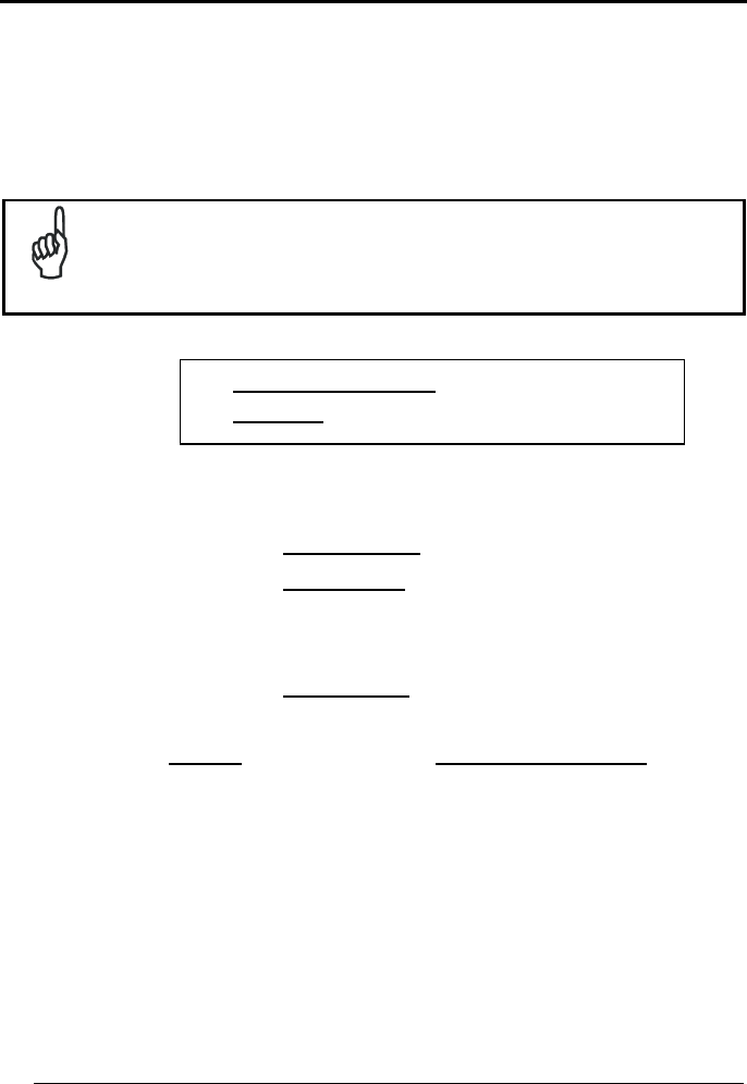
5.2.2 ACK/NACK Protocol and Frame Packing
ACK/NACK Protocol
The transmission protocol takes place between the reader and the Host. The reader
passes its data (code read) to the remote Bluetooth
®
device (Host).
When ACK/NACK is disabled, there is no control from reader to Host transmission,
therefore the reader responds with the good reception tone.
Host with Bluetooth
®
device
GRYPHON
BT
data
good RX
beep
ACK/NACK disabled
REFERENCES
55
5
Host with
Bluetooth
®
device
NACK
data
GRYPHON
BT
data
good RX
beep
A
CK
ACK/NACK enabled
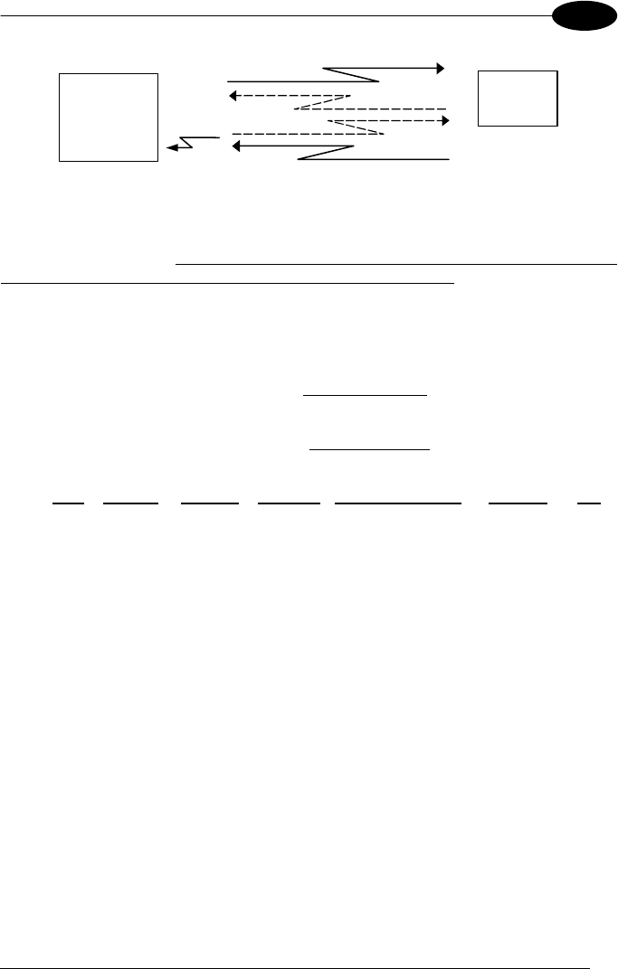
When ACK/NACK is enabled, the Host sends an ACK character (06 HEX) in the case
of good reception or the NACK character (15 HEX) requesting re-transmission, in the
case of bad reception. Only after the ACK character is received by Gryphon™ BT
SH3500 does the reader respond with the good reception tone.
If the reader does not receive an ACK or NACK, transmission is ended after the
Radio Protocol Timeout, par. 5.2.1.
Frame Packing
When Frame Packing is disabled, the Output Message from the Gryphon™ BT
SH3500 reader is sent to the Host as is, see par. 5.1.
If instead, Frame Packing is enabled, the Output Message is "packed" into a Frame
with the following format:
STX Length Control Counter Output Message CRC-16 CR
where:
STX = Frame Start character (02 Hex).
Length = 2 bytes; indicates frame length of the remaining fields (including CR).
Control = 1 byte; indicates message fragmentation. For further details see the DL
Security Protocol documentation on the CD-ROM.
Counter = a loop counter for the Output Message characters (bytes) that cycles from
0 to 255 and then restarts.
Output Message = complete text message from the Gryphon™ BT SH3500 reader
including optional fields as shown in par. 5.1. The maximum length of this field is 304
bytes.
CRC-16) = 2 bytes; 16-bit Cyclic Redundancy Check based on the hex 1021
polynomial and performed on all bytes from Length up to the CRC itself. The MSB is
sent first. For further details see the DL Security Protocol documentation on the CD-
ROM.
CR = Frame Stop character (0D Hex).

GRYPHON™ BT SH3500
56
5
To simplify the management of this frame packing, and to avoid having to develop a
special proprietary software program, included on the CD-ROM are: the DL Security
Protocol example program, (written in Visual Basic), the Windlbt.dll, and the source
code of the example. The example program allows extraction of the data from the
frame, verification of the CRC, discarding any duplicate data (with the same counter
value), and automatic management of Frame Packing and ACK/NACK protocol in
response to each frame.
5.2.3 Power-Off Timeout
If this command is enabled, after the desired timeout in hours, the GRYPHON™ BT
SH3500 batteries are disconnected and all power consumption ceases. To restore
power, press the trigger once. The reader will now be ready to read codes.
Power-off does not effect configuration parameters.
5.2.4 Batch Mode
Batch mode allows codes to be stored in the gun on a FIFO basis whenever the gun
is out of range. In this case radio communication is not suspended and transmission
is attempted after each code read. If transmission cannot be successfully completed,
then the code is added to the list. When the gun returns in range, transmission of the
codes to the cradle resumes automatically, according to the selected communication
protocol, upon simply pressing and releasing the trigger or by successfully reading a
new code.

SYSTEM MANAGEMENT COMMANDS
57
6
6 SYSTEM MANAGEMENT COMMANDS
The following commands carry out their specific function and then exit the
configuration environment.
Command Description
i25?k
i25?k
i25?k
Unbind the reader preventing the connection to a
cradle to which it was previously bound.
i1PGGk
i1PGGk
i1PGGk
Turn the reader off.

GRYPHON™ BT SH3500
58
7
7 TROUBLESHOOTING
Problem Solution
The beeper and LED signal
radio disconnection from the
remote Bluetooth
®
device.
The distance between the remote device and Gryphon™
BT SH3500 may be too far or there may be obstacles to
radio transmission between them.
Reconnect.
The requested radio
connection by Gryphon™ BT
SH3500 Master does not
activate.
Reduce the distance between the devices.
Check that Gryphon™ BT SH3500 is powered (batteries
are charged), that the radio protocol software version is
compatible with Gryphon™ BT SH3500, that there is not
already another BT device connected using the same SPP
profile.
Insert the remote device address again to Gryphon™ BT
SH3500.
Check the Gryphon™ BT SH3500 configuration using the
Transmit configuration command via OM-Gryphon™ BT
SH3500 cradle.
The remote Bluetooth
®
device
recognizes Gryphon™ BT
SH3500 but cannot connect to
it.
Check that there are no limits set to the connection such
as a password.
Check that the radio protocol software version is
compatible with Gryphon™ BT SH3500.
The radio range seems
reduced.
Check that there are no obstacles to radio transmission
between the devices.
An un-connected Gryphon™
BT SH3500 Master accepts a
radio connection from another
Bluetooth
®
Master device.
In this case the Gryphon™ BT SH3500 automatically
forces a disconnection and restarts.
A Gryphon™ BT SH3500
Master fails to make an
automatic connection.
Double-click the trigger to force an immediate retry of the
radio connection or read the "Request Radio Connection"
code in par. Errore. L'origine riferimento non è stata
trovata..
A Gryphon™ BT SH3500
Master remains connected to
a Slave device.
Read the "Request Radio Disconnection" code in par.
Errore. L'origine riferimento non è stata trovata. or
power off the Bluetooth
®
Slave device.
TECHNICAL FEATURES
59
8
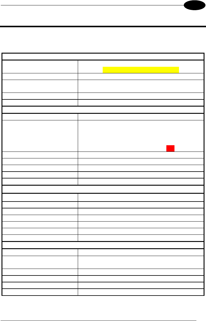
8 TECHNICAL FEATURES
8.1 GRYPHON™ BT SH3500
Electrical Features
Battery Type Li-Ion batteries
1.2 V – 1850 mAh or 2100 mAh
Time of recharge max. 4 hours
Operating autonomy
(typ. continuous reading) >14 hours
Max scan rate 270 scans/sec
Indicators LED, Good Read Spot, Beeper
Optical Features
Sensor CCD solid state (3648 pixels)
Illuminator LED array
Wavelength 630 ~ 670 nm
Max. LED Output Power 0.33 mW
LED Safety Class Class 1 EN 60825-1
Reading field see reading diagram (p. 63)
Max. resolution 0.076 mm, 3 mils
PCS minimum 15% (Datalogic Test Chart)
Reading Pitch angle 65°
Reading Skew angle 80°
Reading Tilt angle 35°
Radio Features
Bluetooth
®
version Bluetooth
®
1.1
Profiles supported Serial Port Profile
Working frequency 2.4000 to 2.4835 GHz
Maximum output power 2.5 mW (class 2)
Range (in open air) 10 m typical
Radio frequency up to 921 Kbps
Effective radiated power <10 mW
Environmental Features
Working Temperature 0° to + 40 °C
Storage Temperature
(without battery) -20°to + 70 °C
Humidity 90% non condensing
Drop resistance 1.8 m
Ambient light immunity 100000 lux (sunlight) / 4000 lux (artificial light)
Protection class IP30

GRYPHON™ BT SH3500
60
8
Mechanical Features
Weight (with batteries) about 280 g. (including battery)
Dimensions 179 x 81 x 98 mm
Material ABS and Polycarbonate molded with rubber
Decoding Capability
Readable codes EAN/UPC, ISBN/ISSN, 2/5 family, Code 39 (plus
Code 32, Cip 39), Codabar, Code 93, MSI, Plessey,
Telepen, Delta IBM, Code 11, EAN 128, Code 128,
ISBT 128, Code 16K, Code 49, RSS family
Other features encryption
8.2 OM-GRYPHON™ BT SH3500
Electrical Features
Supply voltage 9..28 Vdc
Power consumption max. 8 W (charging) *
Indicators
Battery charging (red)
Charge completed (green)
Power (yellow)
Time of recharge max.4 hours
Environmental Features
Working temperature 0° to +40 °C
Storage temperature -20° to +70 °C
Humidity 90 % non condensing
Protection class IP30
Maximum number of devices in the
same area >50
Communications
Interface RS232, Keyboard emulation (AT, XT,
minidin PS/2), USB
Mechanical Features
Weight about 250 g.
Dimensions 208 x 107 x 55.5 mm
Material ABS
* Having a switching regulator inside, the OM-Gryphon™ SH3500 draws the same
power, regardless of the supply voltage, i.e. as the input voltage increases the
current drawn decreases.
TECHNICAL FEATURES
61
8
8.3 STATUS INDICATORS
The reader has three indicators, LED, Beeper and Good Read Spot. The
OM-Gryphon™ BT SH3500 cradle has three LEDs. They signal several operating
conditions which are described in the tables below.
H = high tone M = medium tone L = low tone
GRYPHON™ BT SH3500 READER START-UP
Beeper
¹
Meaning
L L L L H Parameters loaded correctly, radio OK
L L L L H L H L Parameters loaded correctly, no answer from radio
H H H H
long tones
Parameter loading error, reading or writing error in the non volatile
memory
H L H L Hardware error in EEPROM
GRYPHON™ BT SH3500 READER CONFIGURATION
Beeper
¹
Meaning
H H H H Correct entry or exit from Configuration mode
L Good read of a command
L L L Command read error
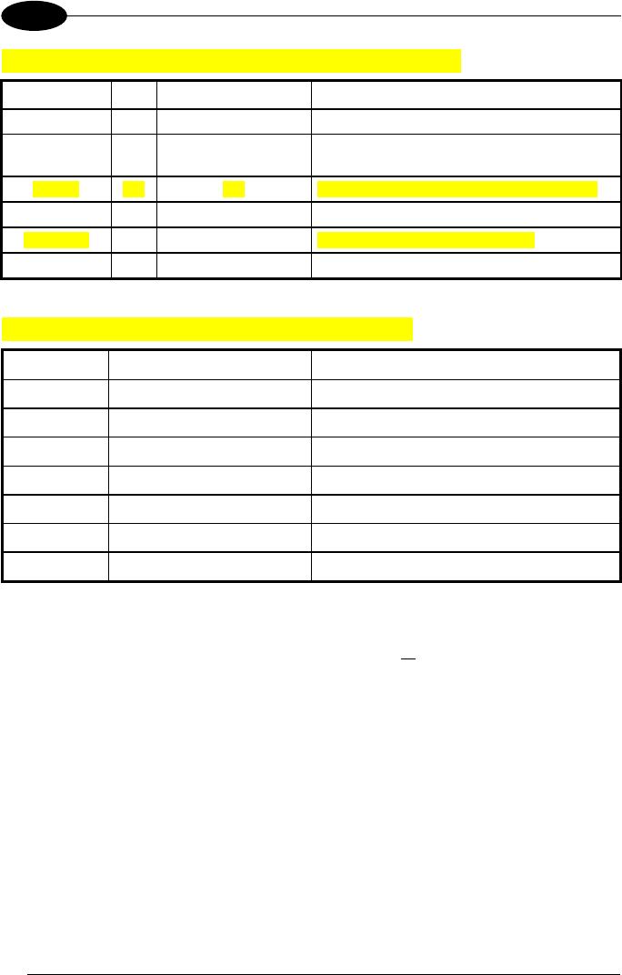
GRYPHON™ BT SH3500 POWER
Beeper
LED Meaning
10 short H 10 short blinks Low Battery
¹ Only the Beeper Intensity command can modify these signals.
GRYPHON™ BT SH3500
62
8
GRYPHON™ BT SH3500 READER DATA ENTRY
Beeper
¹
LED Good Read Spot Meaning
one beep² ON ON Correct read of a code in normal mode
H L long TX error between Gryphon™ BT SH3500 and
remote Bluetooth
®
device
H long ON ON Successful advanced format concatenation
H H H Timeout expired – operation not completed
H H long Error in advanced data formatting
OFF OFF Ready to read a code
GRYPHON™ BT SH3500 READER STATUS
Beeper
¹
LED Meaning
L M M H Radio connection
H M M L Radio disconnection
1 blink / 2 sec. Radio connected
2 blinks / 2 sec. Radio not connected
1 blink / 4 sec. Sleep state and radio connected
2 blinks / 4 sec. Sleep state and radio not connected
ticks Short blinks (Master only) Connection / re-connection attempts
¹ Only the Beeper Intensity command can modify these signals.
² The data entry good read tone is user-configurable with all the Beeper commands in the
Reading Parameters section.
Normally this results in two beeps; the first indicates that the reader has decoded the code,
the second indicates whether the remote Bluetooth
®
device has received the data.
TECHNICAL FEATURES
63
8
OM-GRYPHON™ BT SH3500 CHARGE STATUS
Red LED Green LED Meaning
ON OFF Charging
OFF ON End of charge
Flashing OFF Reconditioning (see par. 2.3)
OFF OFF No gun inserted or Alkaline battery selected
Flashing Flashing Reader not correctly placed onto the charger;
shorted or open battery
OM-GRYPHON™ BT SH3500 POWER/COMMUNICATION
Yellow LED Meaning
ON Power applied
OFF Error in reading EEPROM parameters / Insufficient Voltage
Blinking OM-Gryphon™ BT SH3500 receives commands from the Host
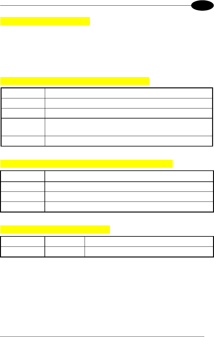
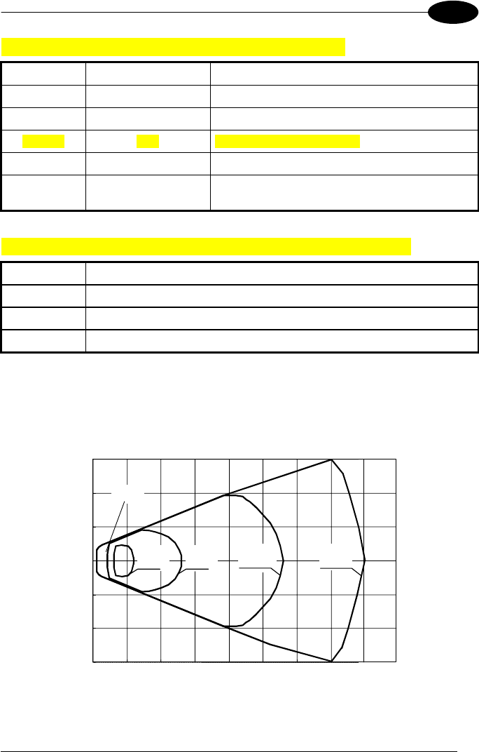
8.4 READING DIAGRAMS
GRYPHON™ BT SH3500100
0 5 10 15 20 25 30 35
-15
-10
-5
0
5
10
15
Reading Zones (10° skew angle)
(cm)
CODE 39
0.13 mm
(5 mils)
EAN13 M=1
0.33 mm
(13 mils)
CODE 39
0.50 mm
(20 mils)
CODE 39
0.076 mm
(3 mils)
0.13 mm
(5 mils)
40

GRYPHON™ BT SH3500
64
A
A HEX AND NUMERIC TABLE
CHARACTER TO HEX CONVERSION TABLE
char hex char hex char hex
NUL 00 * 2A U 55
SOH 01 + 2B V 56
STX 02 , 2C W 57
ETX 03 - 2D X 58
EOT 04 . 2E Y 59
ENQ 05 / 2F Z 5A
ACK 06 0 30 [ 5B
BEL 07 1 31 \ 5C
BS 08 2 32 ] 5D
HT 09 3 33 ^ 5E
LF 0A 4 34 _ 5F
VT 0B 5 35 ` 60
FF 0C 6 36 a 61
CR 0D 7 37 b 62
SO 0E 8 38 c 63
SI 0F 9 39 d 64
DLE 10 : 3A e 65
DC1 11 ; 3B f 66
DC2 12 < 3C g 67
DC3 13 = 3D h 68
DC4 14 > 3E i 69
NAK 15 ? 3F j 6A
SYN 16 @ 40 k 6B
ETB 17 A 41 l 6C
CAN 18 B 42 m 6D
EM 19 C 43 n 6E
SUB 1A D 44 o 6F
ESC 1B E 45 p 70
FS 1C F 46 q 71
GS 1D G 47 r 72
RS 1E H 48 s 73
US 1F I 49 t 74
SPACE 20 J 4A u 75
! 21 K 4B v 76
" 22 L 4C w 77
# 23 M 4D x 78
$ 24 N 4E y 79
% 25 O 4F z 7A
& 26 P 50 { 7B
' 27 Q 51 | 7C
( 28 R 52 } 7D
) 29 S 53 ~ 7E
T 54 DEL 7F

HEX AND NUMERIC TABLE
- 65
A
ik
ik
ik
0
ik
ik
ik
ik
ik
ik
1
2
ik
ik
ik
ik
ik
ik
3
4
ik
ik
ik
ik
ik
ik
5
6
ik
ik
ik
ik
ik
ik
7
8
ik
ik
ik
i"#k
i"#k
i"#k
9
A
i#$k
i#$k
i#$k
i$%k
i$%k
i$%k
B
C
i%&k
i%&k
i%&k
i&'k
i&'k
i&'k
D
E
i'(k
i'(k
i'(k
F
Backspace
ik
ik
Cancels an incomplete configuration sequence