Datamars RIN13003 Mid-Range Industrial RFID High Frequency Reader User Manual
Datamars SA Mid-Range Industrial RFID High Frequency Reader
Datamars >
User Manual
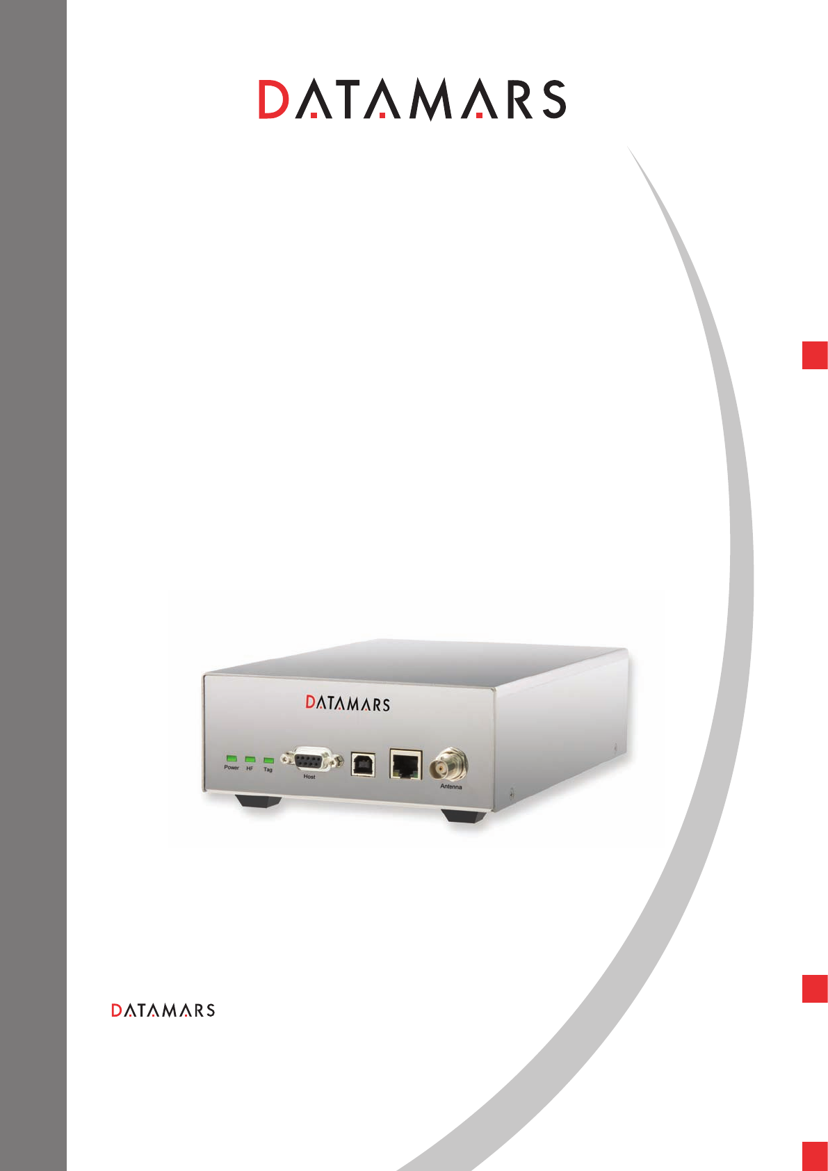
R-IN1300 MID
HF – multi read
TEXTILE ID
USER MANUAL
Version 1.2
Corporate Headquarters:
Via ai Prati
6930 Bedano-Lugano
Switzerland
Phone: +41 91 935 73 80
Fax: +41 91 945 03 30
textile-id@datamars.com
www.datamars.com
Americas Headquarters:
8433 South Av. Bldg., 4-2
Youngstown, OH 44514 USA
Phone: +1 330 758 1240
Fax: +1 330 758 3805
Asia Headquarters:
Northern Region Industrial Estate
179/1 Moo 4, T. Ban Klang, A. Muang
Lamphun, Thailand 51000
Phone: +66 53 582 021
Fax: +66 53 582 680
© 2008 DATAMARS

TABLE OF CONTENTS
1 Introduction........................................................................................................................................... 2
2 Hardware connections........................................................................................................................ 4
3 Operation with Terminal ..................................................................................................................... 6
3.1 List of the commands of the reader.......................................................................................... 6
3.2 Generic Settings .......................................................................................................................... 6
3.3 I-Code I settings........................................................................................................................... 9
3.4 Chip Read and Write Operations .............................................................................................. 9
4 Operation with Graphical User Interface (GUI)............................................................................. 11
4.1 Connecting with the COM (RS-232)....................................................................................... 11
4.2 Connecting with Ethernet (Recommended) .......................................................................... 11
4.3 General Considerations............................................................................................................ 12
4.3.1 Third Party Interface ...................................................................................................... 12
4.3.2 Human Interface............................................................................................................. 12
4.4 Connect (Serial version only) .................................................................................................. 13
4.5 Login (Web Server version only)............................................................................................. 14
4.6 Logout (Web Server version only) .......................................................................................... 15
4.7 Network Setup ........................................................................................................................... 15
4.8 RS 232 Setup............................................................................................................................. 16
4.9 Reader Setup............................................................................................................................. 17
4.10 Advanced Reader Setup ...................................................................................................... 18
4.11 Configurations........................................................................................................................ 18
4.12 Monitor .................................................................................................................................... 19
4.13 Firmware Update................................................................................................................... 21
4.14 How to install the RS-232 interface .................................................................................... 21
4.15 System Requirements ......................................................................................................... 23
5 Technical Specifications for R-IN1300 MID................................................................................... 24
5.1 Operational characteristics ...................................................................................................... 24
5.2 Electrical characteristics........................................................................................................... 24
5.3 Regulations................................................................................................................................. 25
5.3.1 Equipment Modification................................................................................................. 25
5.3.2 EN 300330-1/-2 (europe).............................................................................................. 25
5.3.3 FCC (usa)........................................................................................................................ 25
5.3.4 IC (canada) ..................................................................................................................... 26
5.3.5 CE certification ............................................................................................................... 26
5.3.6 Warranty.......................................................................................................................... 26
Appendix A – Connecting the R-IN1300 MID to a PC with a cross cable....................................... 27
Appendix B - Code length ...................................................................................................................... 28
Appendix C - Troubleshooting ............................................................................................................... 29
R-IN1300 MID Manual – v. 1.2 – August ‘08 1 (29)
1 INTRODUCTION
The Datamars R-IN1300 MID High Frequency (HF) RFID-reader, designed to work in industrial
environments, is resistant to vibrations, electromagnetic interference and able to detect the following
transponder technologies:
T-BT 1320 & T-BT1315 (ISO 15693), HF
The reader is able to find simultaneously more than one High Frequency (HF - multi read)
transponder1.
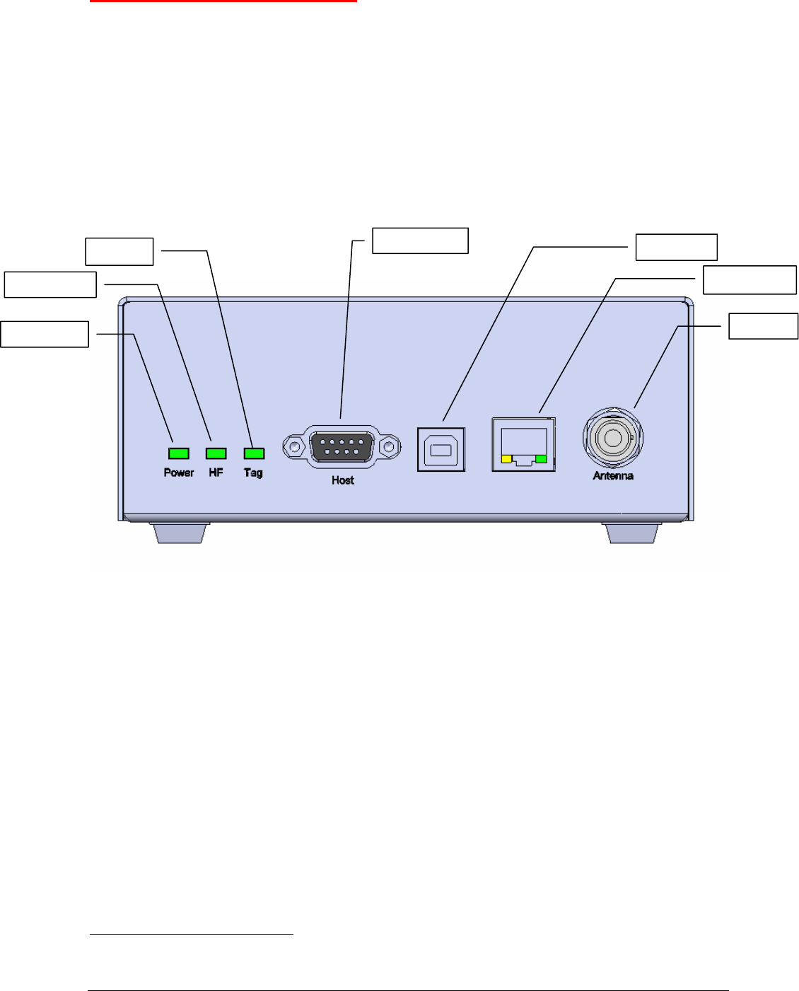
Host Interface
Power indicator
Tag found
Antenna
USB interface
Ethernet interface
HF field indicator
LEDs
Power Light on when the reader is switched on
Tag Light on when one or more transponder are detected
HF High Frequency reading is ON
Antenna
Antenna TX/RX antenna: for example A-ST1330TT / TTL
Interfaces
Host Connect to any serial port (COM) on your PC with RS-232 cable or to
any other RS232 Terminal.
USB USB device port
Ethernet (Web Server) Connect to LAN with a standard Ethernet cable.
For more info in Ethernet communication please request the
“R-IN1300 TCP/IP Dedicated Protocol” manual to
support@datamars.com
1 the quantity of transponders detected and the accuracy can change depending on the used transponder, the environment, the size of the antenna, etc.
R-IN1300 MID Manual – v. 1.2 – August ‘08 2 (29)
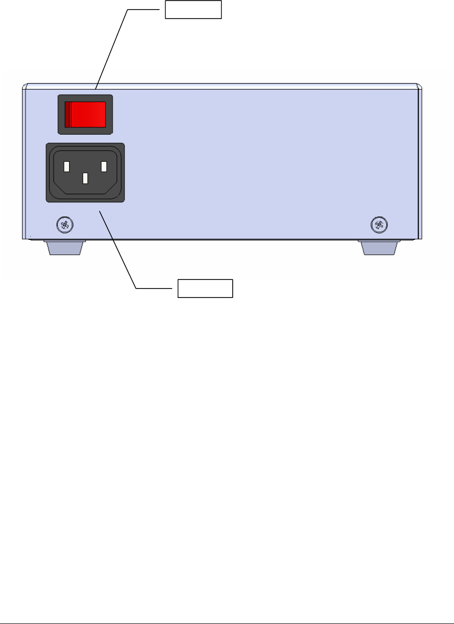
Power Switch Turn ON and OFF the reader.
Power Supply Connect the power supply cable (100-240VAC, 50-60 Hz).
o
Power Switch
Power Supply
R-IN1300 MID Manual – v. 1.2 – August ‘08 3 (29)
2 HARDWARE CONNECTIONS
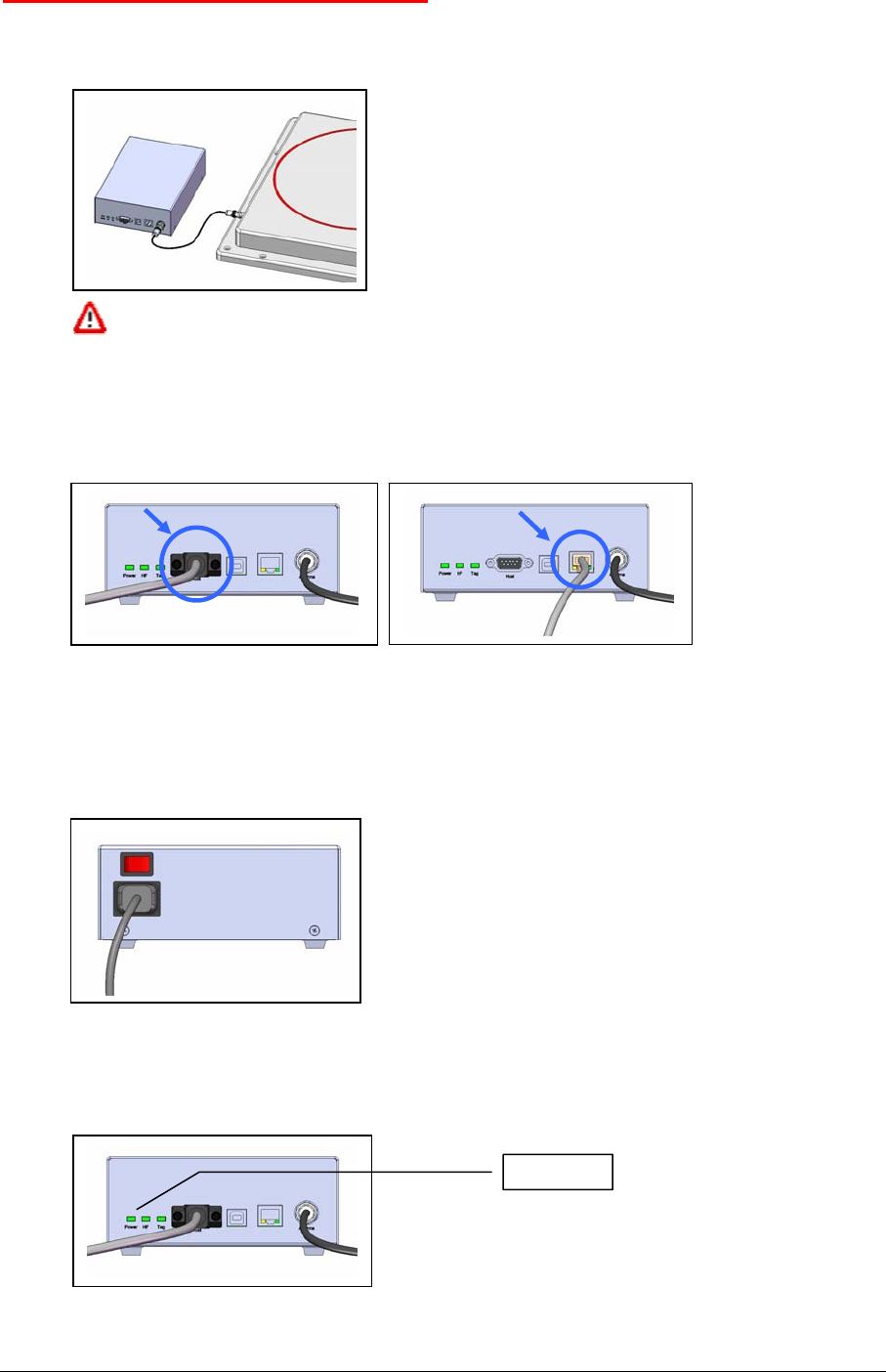
1. Antenna:
Connect the black coaxial cable from the antenna to the connector marked as “Antenna”.
You can not use cable other than the 3.5m coaxial 50Ω cable supplied by
Datamars. Additional extension cables at disposal.
2. PC/Terminal or Ethernet
Connect the serial white cable from the connector marked “Host” to any serial port (COM) on
your PC or the reader “R-IN 1300 MID” can be connected to the LAN just like a PC (Ethernet
cable & RJ-45 connectors).
A direct Ethernet connection between a PC and “R-IN 1300 MID” reader is also possible, with
an Ethernet Cross Cable (supplied together with the reader). Refer to Appendix A for more
details on how to do this.
3. Power
Connect the power cable 110 – 240 V AC and be sure that it is well fixed.
4. Set the Power Switch to ON and check if the green LED (Power) is on.
5. Wait until light “Tag” stop flashing (~20 seconds).
Green light on
R-IN1300 MID Manual – v. 1.2 – August ‘08 4 (29)

IMPORTANT:
Please place the antenna as far as possible from metal surfaces to avoid possible
reading interferences and avoid mounting it in places where regular ventilation is not
granted.
After the reader is turned on for some time the temperature might increase.
Do not plug/unplug any connectors while the reader is turned ON.
R-IN1300 MID Manual – v. 1.2 – August ‘08 5 (29)
3 OPERATION WITH TERMINAL
For operation with terminal use any kind of terminal, e.g. Windows HyperTerminal with the following
settings:
• Bits per second 115200
• Data bits 8
• Parity None
• Stop bits 1
• Flow control None
3.1 LIST OF THE COMMANDS OF THE READER
All commands must be followed by a carriage return (ENTER).
General Commands
Explanation
*d Detect:
returns the UID-list of all the HF transponders in the field
*i Interrupts any continuous mode operation (does not disable the
continuous mode)
*x List of the commands and settings
*v Firmware Version
*se Settings:
Displays the current settings (Notice that the settings are maintained
after power off)
*st Store UIDs
Usage: with the command “*st” switch from the state “Store UIDs off” to the state
“Store UIDs on”. Then start reading with the command “*d”. The detected tags are
not sent to the output devices but are cumulated internally. Using now the command
“*dw” the reading process is stopped and the cumulated detected UIDs are sent to the
output devices all at once.
*dw Download UIDs (this command is coupled with *st – see above)
3.2 GENERIC SETTINGS
General settings
Explanation
*rd Restore default settings
Any previously user defined settings will be deleted and re-
placed by factory defaults.
Confirmation: “Default settings restored”
*co[_] Continuous mode:
*co1 continuous mode on (default)
*co0 continuous mode off
*rh[_] Remove headers:
*rh0 does not remove the headers
*rh1 removes the headers (default)
R-IN1300 MID Manual – v. 1.2 – August ‘08 6 (29)

*ec[_] Echo:
*ec0 echo disabled (default)
*ec1 echo enabled
“echo” makes it possible to view the characters sent to the reader.
*sa[_] Stand alone mode:
*sa0 stand alone mode disabled (default)
*sa1 stand alone mode enabled (detect)
When stand alone mode is enabled, the device will start reading
as soon as it is turned on.
*nl[_] New Line character(s) selection:
*nl0 line feed and carriage return (0x0D 0x0A) (default)
*nl1 line feed (0x0A)
*nl2 carriage return (0x0D)
*nl3 carriage return and line feed(0x0A 0x0D)
*pw[_] Output power:
*pw[0 .. 4000] range of power from 0 to 4000 mW (default 2000
mW)
- Example *pw2000
The selected output power is an approximate value.
*dt[_] Time between UIDs:
This parameter inserts a time delay between the transmission of
codes.
*dt[0..200] range of time between UIDs from 0 to 200 units
(default 0), 1 unit = 10 ms (example: *dt10 >> 100ms)
*lc[_] Lock code:
*lc0 lock code disabled (default)
*lc1 lock code 1 enabled
*lc2 lock code 2 enabled
Details for *lc1:
Any transponder is read just once.
To read a transponder again, another one must be read first.
The transponder is first detected only once without regard to the time spent in the field.
*ti[_] Time out:
*ti[0 .. 180] time parameter for lock code 2 from 0 [s] to 180 [s]
(default 10 [s], example *ti10)
*sk[_] Skip time slot on no response:
*sk0 skip on no response off
*sk1 skip on no response on (default)
*ct[_] Collision threshold parameter:
*ct[0 .. 100] parameter from 0 to 100 (default 33, example *ct33)
*et [_] Communication selection :
*et0 ethernet
*et1 RS232
*et2 RS232 and ethernet (default)
*br[_] baud rate:
*br0 baud rate 9600
*br1 baud rate 19200
*br2 baud rate 38400
*br3 baud rate 57600
*br4 baud rate 115200 (default)
*cl[_] Code length:
See Appendix A for more details.
R-IN1300 MID Manual – v. 1.2 – August ‘08 7 (29)

*cl0 16 characters UIDs (standard, default)
*cl1 15 characters UIDs (Partial code)
*cl2 14 characters UIDs (Partial code)
*cl3 13 characters UIDs (Partial code)
*cl4 12 characters UIDs (Partial code)
*cl5 12 characters UIDs (First character special)
*cl6 11 characters UIDs (Partial code)
*cl7 10 characters UIDs (Partial code)
*cl8 9 characters UIDs (Partial code)
*cl9 8 characters UIDs (Partial code)
Attention: code maybe not unique with the selected code length
*tt[_] Tag technology:
*tt1 tag technology ISO 15693(T-BT1320 T-BT1315) (default)
*tt2 tag technology Philips I-Code I (not available).
Example:
*it1: only ISO
*it2: only I-Code I
*it12: both ISO and I-Code I
*ip[_-_-_-_] Configure the IP (Internet Protocol) number of the reader.
Example:
*ip192-168-1-0
Sets the IP number 192.168.1.0
The default IP number of any new reader is 192.168.0.85
*if Plots the current (TCP/IP) network configuration of the reader
*rg[_] Receiver gain (in case of doubt, do not modify):
Amplification of the received signal.
*rg0, *rg1, *rg2 (default), *rg3: allowed amplification steps
*re[_] Reverse order
*re0 Uid not reversed (default)
*re1 Uid recersed
ISO 15693 settings
ISO 15693 settings
Explanation
*rm[_] Reader request rate:
*rm0 Reader Request Rate: SLOW (1 out of 256)
*rm1 Reader Request Rate: FAST (default) (1out of4)
*mt[_] Modulation type:
*mt0 modulation type ASK
*mt1 modulation type FSK (default)
*tm[_] Tag response rate:
*tm0 Tag Response Rate: SLOW
*tm1 Tag Response Rate: FAST (default)
*mi[_] Modulation index:
*mi0 modulation index 20% (default)
*mi2 modulation index 100%
*ts[_] Time slots ISO-15693:
*ts0 single time slots
*ts1 16 times slots (default)
*qm[_] Quiet mode:
When this mode is enabled the transponder will answer just once
R-IN1300 MID Manual – v. 1.2 – August ‘08 8 (29)
while in the antenna field.
*qm0 quiet mode off (default)
*qm1 quiet mode on
3.3 I-CODE I SETTINGS
*nt[_] Time slots I-Code I:
*ts1 single time slot
*ts4 4 time slots
*ts8 8 time slots
*ts16 16 time slots (default)
*ts32 32 time slots
*ts64 64 time slots
*ts128 128 time slots
*ts256 256 time slots
3.4 CHIP READ AND WRITE OPERATIONS
General considerations for memory Read/Write:
• keep the tags in the field
• do not move them during the read/write operation
• do not read/write more than ca. 10 tags at a time
Chip Read and Write
Explanation
*ri[_] Read the text contained in the memory of the specified chip:
*riUID: UID (the unique identifier of the chip) is a 16-char long
sequence.
The result of *riUID is “UID Text” (separated by a space) where
Text is the content of the memory of the specified chip.
Example:
Command:*riE004010007EFD128
Reply: E004010007EFD128 ThisIsText
The specified chip must be and remain within the magnetic
field!
R-IN1300 MID Manual – v. 1.2 – August ‘08 9 (29)
*wi[_][_] Write a new text into the memory of the specified chip:
*wtUIDText: UID (the unique identifier of the chip) is a 16-char
long sequence. Text a free sequence of char (max 255 bytes).
The result of *wiUIDText is “UID status” where:
status = ‘OK’
status = ‘Out of memory’
status = ‘Error’
status = ‘Tag not in field’
Example:
Command:*wiE004010007EFD128 ThisIsMyNewText
Reply: E004010007EFD128 OK
The specified chip must be and remain within the magnetic
field!
*rt Read the text contained in the memory of any transponder in the
magnetic field:
The result of *rt is a list of “UID Text”-couples.
The specified chip must be and remain within the magnetic
field!
*wr[_] Write a new text into the memory of the detected chips:
The result of *wrText is a message showing the number of tags
having been written and a list of “UID status”-couples where:
status = ‘OK’: success
status = ‘Out of memory’
status = ‘Error’
status = ‘Tag not in field’
The chips must be and remain within the magnetic field!
R-IN1300 MID Manual – v. 1.2 – August ‘08 10 (29)
4 OPERATION WITH GRAPHICAL USER INTERFACE (GUI)
The new R-IN1300 MID has 2 modes of operation: one RS-232 ASCII interface based on a terminal
(i.e. MS HyperTerminal) and another with a graphical user interface. For more details on the ASCII
RS-232 interface refer to the specific chapter 4.6.
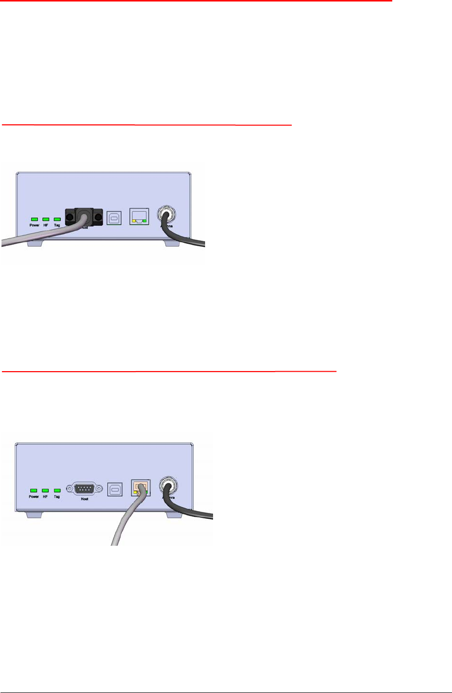
The R-IN1300 MID can connect to the Graphical User Interface (GUI) via 2 different interfaces: RS-
232 or Ethernet TCP/IP:
4.1 CONNECTING WITH THE COM (RS-232)
The reader “R-IN 1300 MID” can be connected to a PC with a serial connection.
To use the RS-232 interface, a software installation is necessary. Insert the CD-ROM supplied with
the reader, the installation will start automatically. Follow the instructions.
In case the installation does not start, open the CD and double click on “install”.
At the end of the installation procedure the necessary software will be found in the Start menu.
4.2 CONNECTING WITH ETHERNET (RECOMMENDED)
The reader “R-IN 1300 MID” can be connected to the LAN just like a PC (Ethernet cable & RJ-45
connectors). No software installation required.
A direct Ethernet connection between a PC and “R-IN 1300 MID” reader is also possible, with an
Ethernet Cross Cable (supplied together with the reader). Refer to Appendix A for more details on
how to do this.
In both cases the reader “R-IN 1300 MID” must be provided with a correct IP-Address (DHCP is not
available. Thus the reader is not yet able to get its IP-address automatically).
R-IN1300 MID Manual – v. 1.2 – August ‘08 11 (29)

To provide the “R-IN 1300 MID” reader with an IP-address, it is recommended to configure it with the
supplied cross cable (or RS-232 interface), at least for the first time, in order to avoid IP conflicts in
your network. See appendix A for more details on how to connect your reader with a cross cable.
When the reader has its own IP-Address on the LAN (or with cross cable), you can go to login-page of
the reader and have access to the configuration-, monitoring- and administrator- tools. To do this,
open a web browser (Internet Explorer, Firefox, etc.) and type http://192.168.0.85 (or the IP that you
have configured) in the address bar.
4.3 GENERAL CONSIDERATIONS
4.3.1 THIRD PARTY INTERFACE
The “R-IN 1300 MID Reader” always listens to incoming TCP/IP connections on port 1026 (TCP/IP
socket).
Using this dedicated TCP/IP socket, third party applications can connect to, exchange data with,
configure and monitor the “R-IN 1300 MID Reader”.
Refer to the “R-IN 1300 TCP/IP Dedicated Protocol” (UM001030) for a detailed description of the
whole communication protocol and syntax.
4.3.2 HUMAN INTERFACE
(Valid both for RS-232 interface and Ethernet interface)
The interface (graphical program running on PC or on the browser) shows the configuration of the
reader “R-IN 1300 MID” as a tabbed panel. Each panel groups logically tied parameters.
The SAVE, DEFAULT and CANCEL buttons act locally on the parameters of the current active tab.
The REFRESH button acts on the whole configuration (on all tabs).
To save the configured settings shown in the tab, press the SAVE button.
To restore the factory default settings of the current tab, press the DEFAULT button.
To undo changes done on the current tab, press the CANCEL button.
To view the actual parameters of the reader on all tabs, press the REFRESH button.
The parameters shown in the tabs may depend on each other. The selection of some options could
make some parameters “meaningless” in this context. In such cases relevant parameters are shown
normally while “meaningless” parameters are masked/disabled.
All parameters described in this manual refer to the “High Frequency Reader R-IN 1300 MID” with
exception of the parameters contained in the “Combo Setup Panel” and “Advanced Setup Panel”
which refer to the “Low Frequency Reader R-IN 7500”.
The graphical application requires a Java2 or Java5 plug-in. If the requested plug-in is already
installed on your PC, you are immediately able to run the application.
Otherwise the system will try to connect to the WWW to download the plug-in. In this case, follow
every installation step always accepting the defaults suggested by the system.
R-IN1300 MID Manual – v. 1.2 – August ‘08 12 (29)
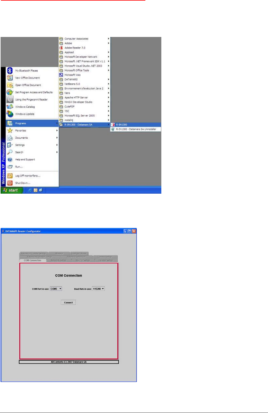
4.4 CONNECT (SERIAL VERSION ONLY)
Start the RS-232 interface selecting the entry “R-IN 1300” as shown in the picture.
Before starting the RS-232 interface the very first time, you have to run the corresponding installer
(see paragraph 4.17)
Then select the COM-Port and Baud-Rate of your terminal which must correspond to the Baud-Rate
of the reader. In case of malfunction of the serial communication, try reducing the Baud-Rate of the
reader and then reconnect.
R-IN1300 MID Manual – v. 1.2 – August ‘08 13 (29)
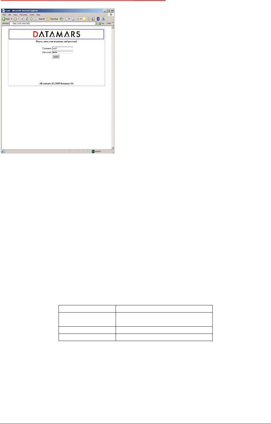
4.5 LOGIN (WEB SERVER VERSION ONLY)
The interface running on the browser permits access to users only via login (user name & password):
attempts to join the configuration- and monitoring tools directly via bookmarks are prevented from the
system.
A user trying to connect while the system is already occupied (i.e. by another user having logged in
before) gets access in read-only mode thus preventing the configuration from being modified at the
same time by more users.
When the user closes the browser, the system becomes free, allowing other users to login and get
read-write mode.
If the currently logged in user forgets to close the browser, she/he is automatically disconnected from
the system. This is done on timeout-basis: if nobody presses any button for a time period longer than
10 minutes, the system makes the session available for other users.
The administrator (only she/he) can force the system to disconnect users when the system is kept
busy too long.
The default accounts are defined as follows, passwords can be changed.
User Names Default Passwords
admin Admin (read, modify and
administrative rights )
user1 1234 (read and modify rights)
user2 1234 (read-only rights)
R-IN1300 MID Manual – v. 1.2 – August ‘08 14 (29)
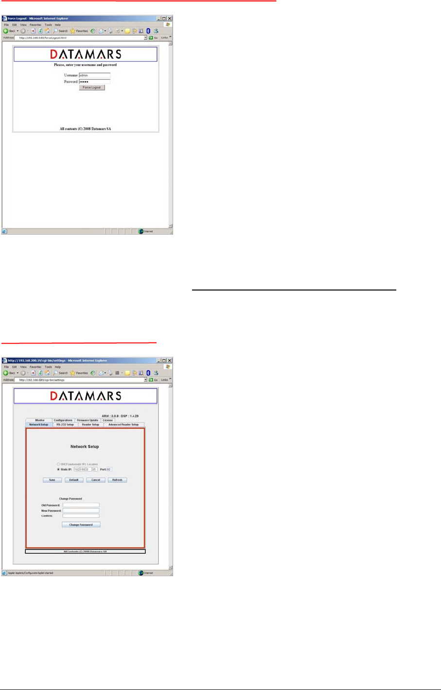
4.6 LOGOUT (WEB SERVER VERSION ONLY)
The “administrator” can disconnect every session to the reader in case of suspect use of the GUI (i.e.
a user is logged in for too much time monopolizing the system).
The “administrator” must go to the URL: http://ip-address-of-the-reader/forceLogout.html and give
her/his user password.
4.7 NETWORK SETUP
The “Network Setup” tab allows users to specify whether the reader has a fixed IP-Address (in this
case the ip-address and port must be specified) or a dynamic one (DHCP) not available yet. After
having changed the IP-Address, the browser must be closed and a new login must be done using the
new IP-Address of the reader.
R-IN1300 MID Manual – v. 1.2 – August ‘08 15 (29)
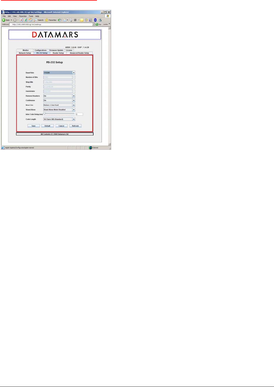
From this tab it is also possible to change the password of the current user. The current password
must be specified, the new password must be confirmed (specified twice). Pressing the CHANGE
PASSWORD button, the request is submitted to the reader and the user is told about the success/
failure of the sent command.
4.8 RS 232 SETUP
The “RS-232 Setup” allows users to specify the properties of the serial connection.
The “Baud Rate” and “New Line” fields are implemented on the interface (PC or browser) as well as
on the reader.
The fields “Number of bits”, “Stop bits”, “Parity”, “Handshake” are implemented on the interface but
not yet on the reader. Changes done on these fields do not yet affect the system behaviour.
The “Remove Header” field informs the reader that expected responses must contain only essential
information (explanations, warnings and miscellaneous information must be cut off).
The “Continuous” field enables/disables the continuous-reading mode. If this property is enabled,
inventory-cycles are automatically repeated otherwise only one cycle is done.
The “Stand Alone” field has following meanings:
Stand Alone Mode Disabled: after the reader has been turned on, it waits for the start-reading
command to come. Until this moment, it remains in a not-reading state.
Stand Alone Mode Enabled Detect: at power on the reader starts reading automatically and sends
the found UIDs after each inventory cycle.
The “Inter Code Delay” field specifies how much time (in sec/100) must be awaited between the
sending of two subsequent UIDs.
The “Code Length” field specifies the length and format of the sent UIDs.
R-IN1300 MID Manual – v. 1.2 – August ‘08 16 (29)
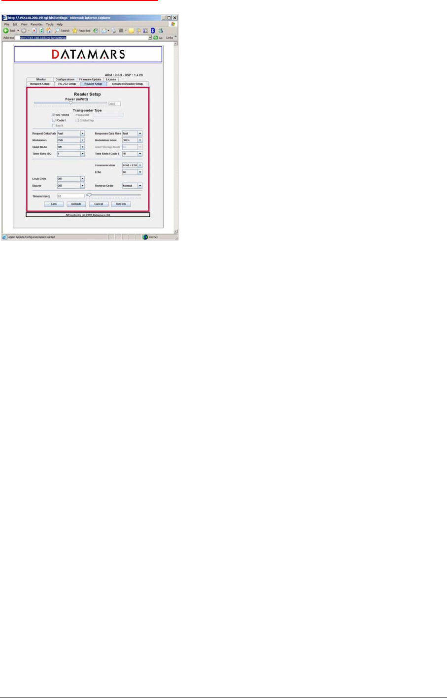
4.9 READER SETUP
The “ReaderSetup” tab allows users to specify overall properties of the reader.
It is possible to specify:
the antenna power:
0 mW – 4 000 mW (1000 mW = 1 W; 2000 mW = 2 W; etc. )
the technologies of the transponders being used:
ISO-15693
I-Code I
the ISO-15693 properties (see corresponding ISO-specification)
Request/Response Data Rate
Modulation Type/ Modulation Index
Quiet Mode /Quiet Storage
Time Slots
The “Lock Code” field specifies a particular behaviour of the reader: Details for LockCode 0:
Disabled.
Details for LockCode 1: Any transponder is read just once. To read a transponder again, another
one must be read first.
Details for LockCode 2: The transponder is first visible when entering the magnetic field the first time
and it is detected only once without regard to the time spent in the field. A chip having left the
magnetic field can be read again only having spent an amount of time T outside of it. If the time spent
outside the magnetic field is less than T, the chip cannot be detected.
The “Communication” field specifies on which output channels the reader must write the found UIDs.
The “Echo” field specifies whether the user-input written onto the terminal (RS-232) must be shown
on the screen or not.
The “Reverse Order” field specifies the representation of the UIDs:
Reverse Order Off : Uids are not reversed
Reverse Order On : Uids are reversed
R-IN1300 MID Manual – v. 1.2 – August ‘08 17 (29)
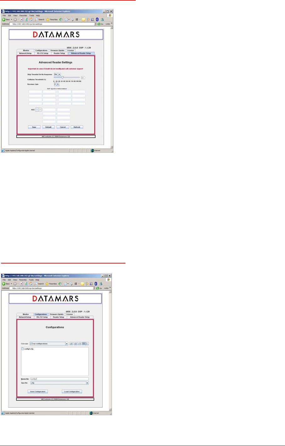
4.10 ADVANCED READER SETUP
The “Advanced Reader Setup” tab allows users to specify advanced properties of the reader.
The “Skip Timeslot On No Response” field specifies whether or not empty timeslots must be skipped
(that’s to say “wait no longer if it seems that no tag is here”).
It is recommended to enable this feature.
The “Collision Threshold” field is a highly complex parameter. It is recommended to set it to 33.
The “Receiver Gain” field specifies the sensitivity of the reader’s input ( 0: less sensitive 3: most
sensitive).
4.11 CONFIGURATIONS
R-IN1300 MID Manual – v. 1.2 – August ‘08 18 (29)
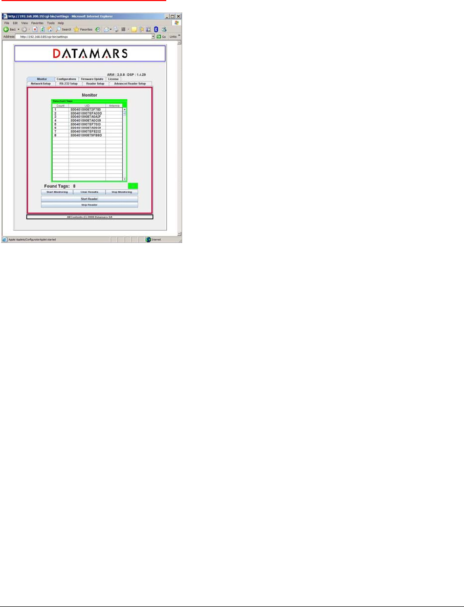
The "R-IN 1300 Reader" offers a tool giving the user the possibility to save and/or reload configuration
files.
First of all select the tab named "Configurations".
To save the currently active configuration, select the destination folder using the navigator, write the
destination file name in the related input field and then press the button "Save Configuration".
To load a previously saved configuration, select the folder and file using the navigator and then press
the button "Load Configuration".
4.12 MONITOR
The monitor tab is used for verifying whether the reader is active or not.
The “Start Reader” button makes the reader start its inventory cycles.
The “Stop Reader” button makes the reader suspend its reading process.
The “Start Monitoring” button permits to display the UIDs of the chips found by the reader.
The “Clear Result” button clears the UIDs display.
The “Stop Monitoring” button stops the display.
The led “D” (detection) is green if the reader sends UIDs, red otherwise
PLEASE NOTE:
UIDs are displayed only once: duplicated UIDs are not diplayed again! This could give the
impression that the reader does not work correctly but this is NOT true. Please, in this case press the
“Clear Result” button.
If you press the “Stop Reader” button, the reader stops its reading process. Please click this button
only if you are sure that the suspension of the reader activities does not cause the loss of important
data.
TAG READ/WRITE OPERATIONS
If Tag-Read/Write operations must be performed, the monitoring-process must be started (press the
“Start Reader”- and the “Start Monitoring”- buttons).
The desired tag (only one) must now be selected from the list of the found chips just by clicking on its
corresponding UID with the left button of the mouse.
Once the UID has been selected, the user starts the Tag-Read/Write operations by clicking the right
button of the mouse.
At this point a small pop-up window opens automatically. It shows the UID of the selected chip, its
related current text and an input field where a new text can be defined (see picture below).
R-IN1300 MID Manual – v. 1.2 – August ‘08 19 (29)
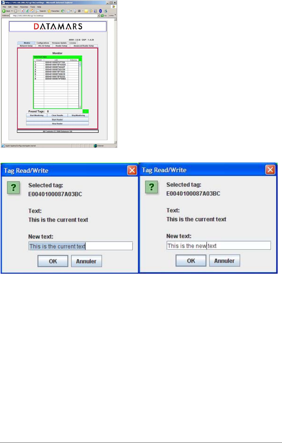
The user can now specify the new text using the input field and then confirm with the OK-button in
order write the new text into the tag-memory.
Of course Tag-Read/Write operations can be cancelled with the “cancel-button” or by closing the “Tag
Read/Write” pop-up window.
The user is told about the result of the Chip-Read/Write operation by another pop-up window.
Please note that these reading/writing operations are only possible if the chip remains within the
magnetic field.
These reading/writing operations are allowed with both the RS232 and Ethernet GUIs. Because of
technical reasons when using the RS232 GUI, it is first necessary to stop the reading process by
clicking the stop-monitoring button. Afterwards proceed according to the description above.
R-IN1300 MID Manual – v. 1.2 – August ‘08 20 (29)
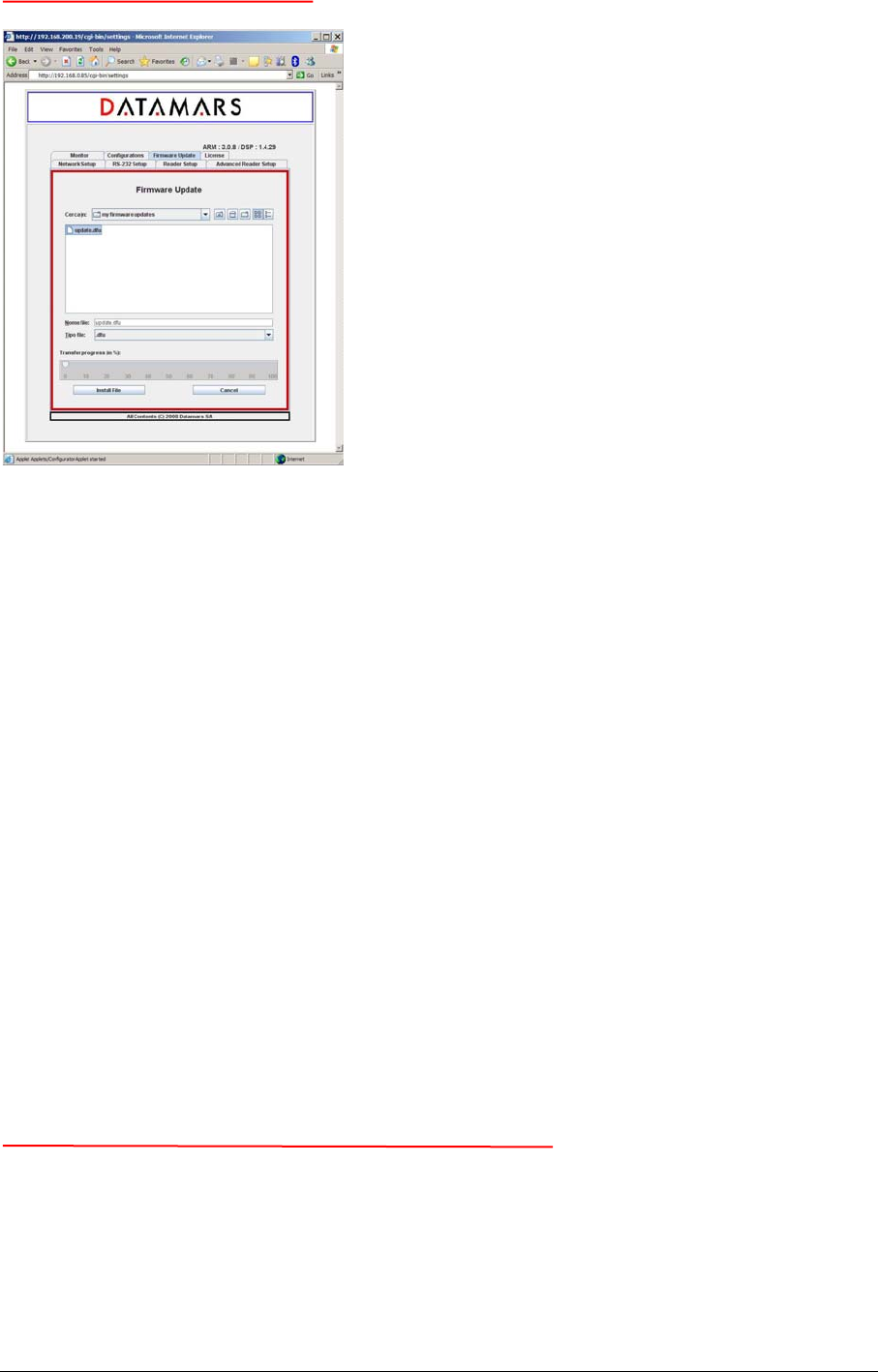
4.13 FIRMWARE UPDATE
The GUI-version running on the browser offers the user a tool to update the software of the “R-IN
1300 Reader”.
First of all select the tab named "Firmware Update" and select the file containing the new software
(delivered by Datamars SA) using the navigator and then press the “Install File”-button.
The new software is now transferred (copied) from the PC to the reader. A slider tells about the
transferring-process status.
If the transferring-process hangs or if the user notices that a wrong file has been transferred, the user
can cancel the operation and remove the transferred file clicking the “Cancel”-button.
When the whole file has been completely transferred onto the reader, the user is prompted by a pop-
up window if she/he really wants to install and activate it. The user can confirm or cancel the
operation.
If the user decides to continue and to activate the new software, she/he MUST wait until the whole
installation-process is terminated. At the end of the installation, the reader performs a reboot and the
browser connection of the user is consequently closed (the warning “Connection closed” appears on
the browser). Now the user can perform login again and verify the correct working of the new
software.
NB: The installation of the new software can require a couple of minutes: during this period it is
ABSOLUTELY FORBIDDEN to turn off the reader.
4.14 HOW TO INSTALL THE RS-232 INTERFACE
Insert the “Product CD R-IN 1300 MID” into the CD-Drive of the host-PC and double click the icon
representing the program “R-IN1300-MID_windows_3_0.exe” and follow every installation step.
Always accept the default options will install every component correctly. You can even customize
your installation specifying other options than the default ones.
R-IN1300 MID Manual – v. 1.2 – August ‘08 21 (29)
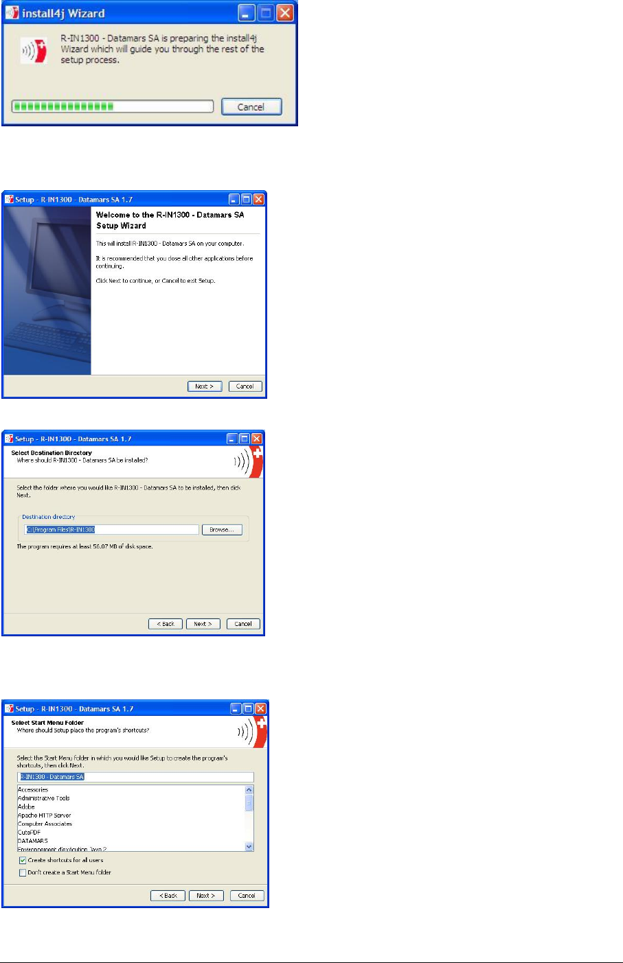
After double-click on the “R-IN1300-MID_windows_3_0.exe”-icon: following picture will appear.
After this preparation step, you will see this input mask. Click “Next”.
You can now specify the destination folder. You can simply accept the default folder by clicking
“Next”.
R-IN1300 MID Manual – v. 1.2 – August ‘08 22 (29)
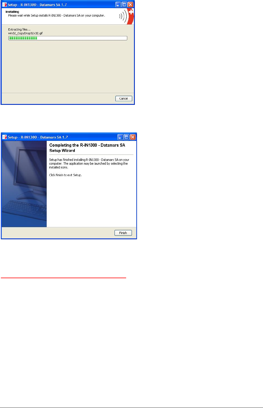
Wait now till the installer terminates its task.
Now you have successfully installed the RS-232 Serial Interface: Click “Finish”
4.15 SYSTEM REQUIREMENTS
OS: MS Windows 98 or higher, MAC OS X, Linux
Software: Java 2 Runtime Environment v. 1.4 or higher.
Hardware: 32 MB of RAM, 50MB of free hard disk space.
R-IN1300 MID Manual – v. 1.2 – August ‘08 23 (29)
5 TECHNICAL SPECIFICATIONS FOR R-IN1300 MID
5.1 OPERATIONAL CHARACTERISTICS
The DATAMARS SA RFID reader R-IN1300 MID is an integrated analog system for RFID-
Applications (RFID=radio frequency identification) which works at 13.56MHz. It allows reading data
stored into ISO-RFID transponders or ISO-Labels at 13.56 MHz. Single and Multiread operation are
supported. The communication between the reader and the transponder is based on the ISO 15693
(Part 1-3) protocol.
All transponders (contact less memories) are powered by a transmitted carrier radio wave at
13.56MHz and are compliant with the ISO 14443-B recommendation for the transfer of power and
signals via radio transmission. For this purpose the reader R-IN1300 MID amplitude, modulates the
data on the carrier using amplitude shift keying (ASK) and the tag replies by load modulating the data
on the carrier.
Once the reader is connected to an appropriate client-network (via dedicated computer) it works
based on the installed software like a server providing the received data from the transponders to the
final client-application.
The service software helps to control and update the reader in user-friendly way.
R-IN1300 MID supports different antennae as well as multiple configurations.
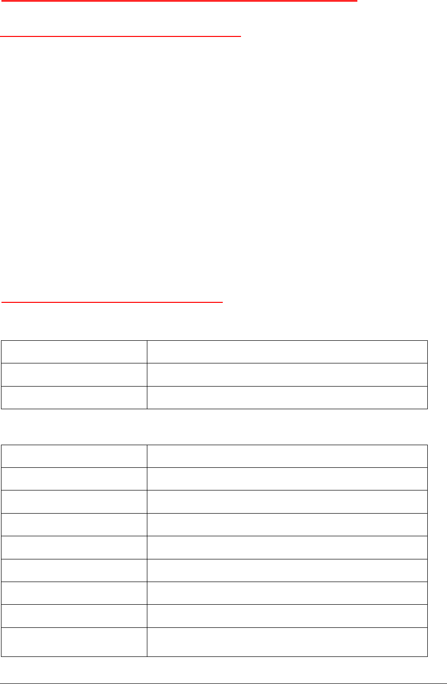
5.2 ELECTRICAL CHARACTERISTICS
Electrical characteristics (without antenna)
POWER SUPPLY AC 100-240V 1A 50-60 Hz
POWER CONSUMPTION 35 W
ANTENNA OUTPUT POWER 4 W
Technical characteristics
OPERATING FREQUENCY 13.56 MHz
OPERATING TEMPERATURE 0°C - 40°C / 32°F - 104°F
DIMENSIONS 222 x 152 x 59 (mm) / 8.7 x 6.0 x 2.3 (inches)
WEIGHT 1.5 kg
TRANSPONDER TYPE ISO15693 (T-BT 1320 or T-BT1315)
ANTI COLLISION Yes
COMMUNICATION PROTOCOL RS-232, USB (upon request), TCP/IP (Ethernet)
AUTO TUNING No
READING SPEED Depend on number of transponder and technology (up to
40/s)
R-IN1300 MID Manual – v. 1.2 – August ‘08 24 (29)
READ/WRITE Read / Write
EMC High attenuation characteristics (~30÷60 dB)
IP PROTECTION DEGREE IP30
MAX. READABLE TRANSPONDERS 1000 pieces
Hot The housing might become hot!
5.3 REGULATIONS
5.3.1 EQUIPMENT MODIFICATION
Equipment modifications not expressly approved by Datamars SA, CH-6930 Bedano, the party
responsible for FCC compliance, are forbidden. Such modifications could void the user’s warranty and
authority to operate the equipment and cause hazardous conditions.
5.3.2 EN 300330-1/-2 (EUROPE)
The R-IN1300 MID system is a sending and receiving equipment and is in accordance with the R &
TTE directive
EN 300 330-1/-2.
The R-IN1300 MID system fulfils the requirements of this regulation.
5.3.3 FCC (USA)
This device complies with Part 15 of the FCC Rules. Operation is subject to the following two
conditions: (1) This device may not cause harmful interference, and (2) This device must accept any
interference received, including interference that may cause undesired operation.
Any changes or modifications not expressly approved by the party responsible for compliance could
void the user’s authority to operate the equipment.
NOTE: This equipment has been tested and found to comply with the limits for a Class B digital
device, pursuant to Part 15 of the FCC Rules. These limits are designed to provide reasonable
protection against harmful interference in a residential installation. This equipment generates, uses
and can radiate radio frequency energy and, if not installed and used in accordance with the
instructions, may cause harmful interference to radio communications. However, there is no
guarantee that interference will not occur in a particular installation. If this equipment does cause
harmful interference to radio or television reception, which can be determined by turning the
equipment off and on, the user is encouraged to try to correct the interference by one or more of the
following measures:
-- Reorient or relocate the receiving antenna.
-- Increase the separation between the equipment and receiver.
-- Connect the equipment into an outlet on a circuit different from that to which the receiver is
connected.
-- Consult the dealer or an experienced radio/TV technician for help.
R-IN1300 MID Manual – v. 1.2 – August ‘08 25 (29)

5.3.4 IC (CANADA)
This Class B digital apparatus complies with Canadian ICES-003.
Cet appareil numérique de la classe B est conforme à la norme NMB-003 du Canada.
The device has been designed to operate with the antennas listed below, and having a maximum gain
of 2 dB. Antennas not included in this list or having a gain greater than 2 dB are strictly prohibited for
use with this device. The required antenna impedance is 50 ohms.
List of antennas: Datamars antenna A-ST1330 TT
Please ask for more antennas which are not listed above.
In order to reduce potential radio interferences to other users, select the antenna type and gain as
follows:
equivalent isotropically radiated power (e.i.r.p.) not higher than the permitted one for a successful
communication.
Operation is subject to the following two conditions:
(1) this device may not cause interference, and
(2) this device must accept any interference, including interference that may cause undesired
operation of the device.
5.3.5 CE CERTIFICATION
The system R-IN1300 MID is in accordance with the requirements of protection, which are defined in
the regulation concerning the electromagnetic tolerability EN301 489-1, -3, emitted by the council for
the harmonisation of regulations in the member countries. The European Community regulation for
Low Frequency, EN 60950, is respected.
The R-IN1300 MID system fulfils the requirements of this regulation.
5.3.6 WARRANTY
If the reader is opened by not certified personnel by mistake the warranty is voided and we cannot
guarantee the fulfillments of the above-mentioned regulations.
R-IN1300 MID Manual – v. 1.2 – August ‘08 26 (29)
APPENDIX A – CONNECTING THE R-IN1300 MID TO A PC WITH A CROSS CABLE
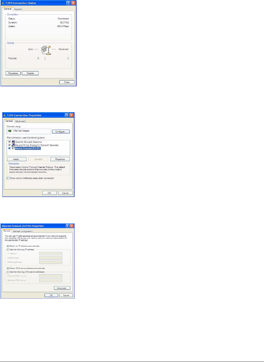
If the reader “R-IN 1300 MID” is directly connected to a PC, you must still do following steps:
Open the “Network Connections” frame of Windows (Hint: Start -> Settings -> Network
Connections) and double-click the entry corresponding to the connection you intend to use to
communicate with the reader. You will see a similar frame:
Click the button “Properties” of the tab “General” to get access to the “Connection Properties” frame. You
will see a similar frame:
Highlight the “Internet Protocol (TCP/IP)“ and click the “Properties” button to get access to the
“Internet Protocol (TCP/IP) Properties” frame. You will see a similar Frame:
Note exactly the current configuration of the tab “General” in order to be able to restore it.
Click the “Use the following IP address” radio-button and specify an IP in the same range of the
readers IP (i.e. 192.168.1.1), the subnet-mask (255.255.255.0). You can ignore the “Default
Gateway”.
Leave the configuration tool confirming by clicking the OK button.
R-IN1300 MID Manual – v. 1.2 – August ‘08 27 (29)

APPENDIX B - CODE LENGTH
In terminal mode you can configure the reader to return the UID code in 4 different formats:
1. *cl0:
Standard 16 characters UID
2. *cl1 to *cl9:
The reader returns only the right most digits of the original 16 digit UID.
With this format it is not possible to guaranty the uniqueness of the codes !
3. *cl5:
The reader returns 12 digits code in the fashion of “cl2”, but in this case the first (left) chapter
ranges from “G” to “Z” instead of from “0” to “F”.
With this format it is not possible to guaranty the uniqueness of the codes !
R-IN1300 MID Manual – v. 1.2 – August ‘08 28 (29)
APPENDIX C - TROUBLESHOOTING
If you run into any problem using your reader, use the following table to troubleshoot the problem. If
the problem persists, contact support at support@datamars.com or +41 91 935 73 80.
SYMPTOM CAUSE AND/OR CORRECTIVE ACTIONS
There are transponders on the antenna but the
software displays no UID.
• Is the antenna cable connected to the
reader?
• Is the antenna connected to the connector
named “1”?
• Are the transponders you want to read
specified in the options?
• Is the HF led on?
Î If the four previous points didn’t solve the
problem turn the reader off, wait 10 seconds
before turning the reader on again
Bad reading or low reading distance
• The antenna is near metallic objects or
noise source like electric motors?
Î Try to move the antenna and the reader
away from these objects.
The reader reads transponder (Tag LED lights
on) but the software displays no UID
• Is the RS-232 cable well connected ti the
Host Interface?
• Is the software set 115200 bps – 8 – N – 1
– N?
Î Verify the connection
R-IN1300 MID Manual – v. 1.2 – August ‘08 29 (29)
Corporate Headquarters:
Via ai Prati
6930 Bedano-Lugano
Switzerland
Phone: +41 91 935 73 80
Fax: +41 91 945 03 30
textile-id@datamars.com
www.datamars.com
Americas Headquarters:
8433 South Av. Bldg., 4-2
Youngstown, OH 44514 USA
Phone: +1 330 758 1240
Fax: +1 330 758 3805
Asia Headquarters:
Northern Region Industrial Estate
179/1 Moo 4, T. Ban Klang, A. Muang
Lamphun, Thailand 51000
Phone: +66 53 582 021
Fax: +66 53 582 680