Datamars WALKBY Stationary RFID Reader User Manual F310
Datamars SA Stationary RFID Reader F310
Datamars >
User manual
1
USER MANUAL
WALK BY
Universal Scanning Station

Walk By Stationary Reader 2
Contents:
1 DESCRIPTION ............................................................................................................................... 4
1.1 FRONT OVERVIEW ......................................................................................................................... 4
1.2 BACK OVERVIEW............................................................................................................................ 5
2 HOW TO SET UP THE SYSTEM ................................................................................................... 6
3 USER INTERFACE......................................................................................................................... 7
3.1 KEYPAD ........................................................................................................................................ 7
3.2 ON BUTTON .................................................................................................................................. 7
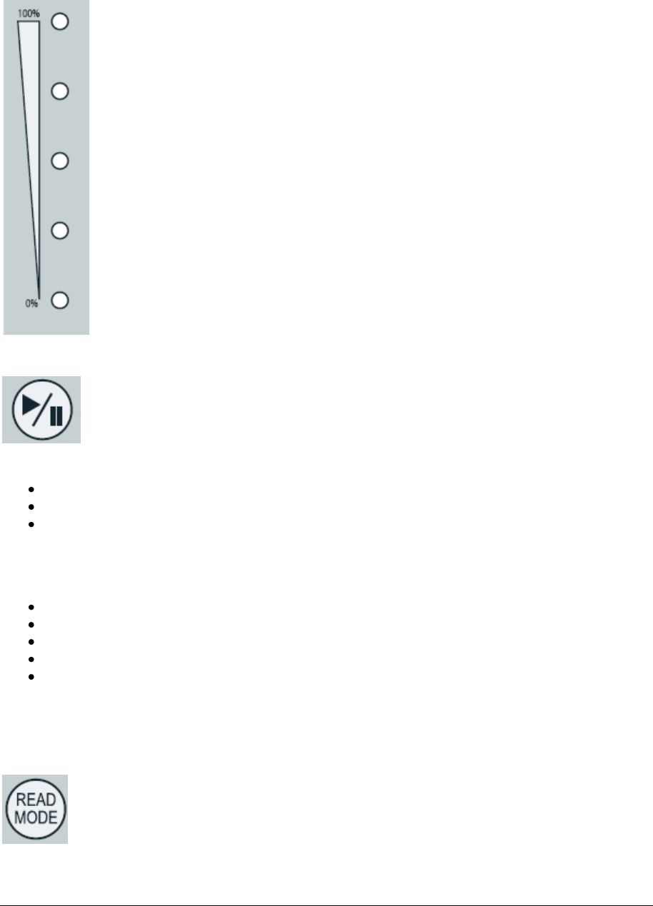
3.3 BATTERY LEVEL BAR ...................................................................................................................... 8
3.4 PLAY/PAUSE BUTTON ................................................................................................................. 8
3.5 READ MODE BUTTON .................................................................................................................. 8
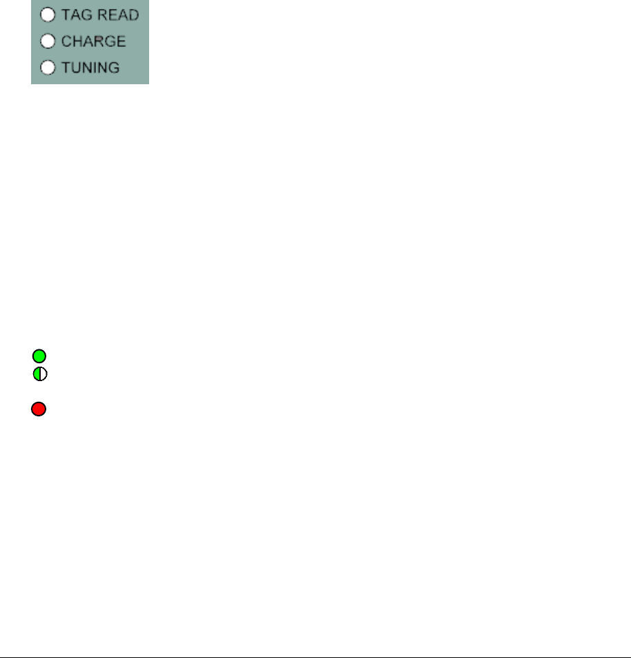
3.5.1 Continuous mode .............................................................................................................. 9
3.5.2 Buffered mode ................................................................................................................... 9
3.5.3 Single mode ....................................................................................................................... 9
3.6 STATUS LEDS .............................................................................................................................. 9
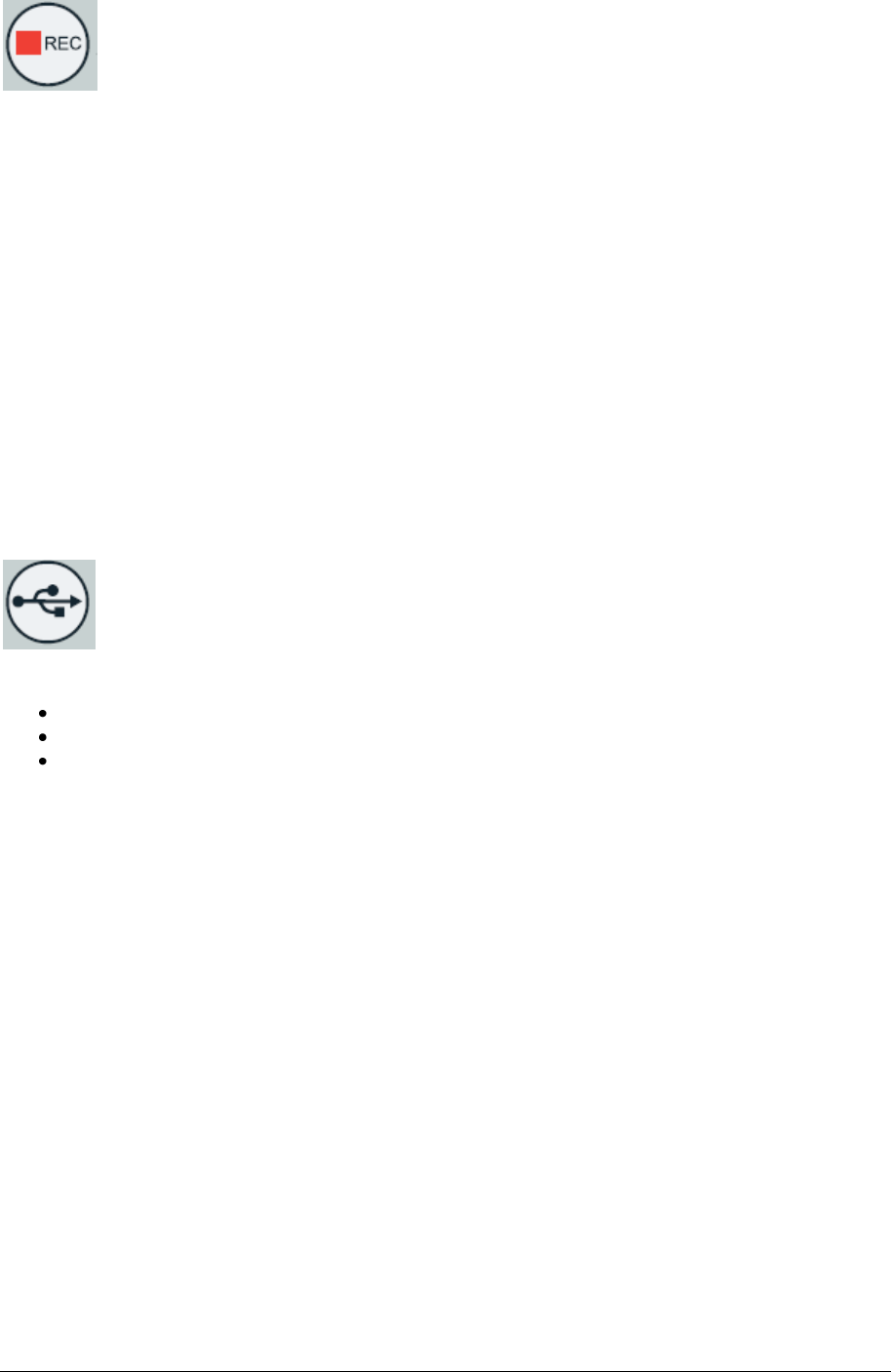
3.6.1 Tag Read LED ................................................................................................................... 9
3.6.2 Charge LED ....................................................................................................................... 9
3.6.3 Tuning LED ........................................................................................................................ 9
3.7 AUTOTUNING ................................................................................................................................. 9
3.8 REC BUTTON .............................................................................................................................. 10
3.9 USB MODE BUTTON .................................................................................................................... 10
3.9.1 Mass Storage .................................................................................................................. 10
3.9.2 Virtual Com Port .............................................................................................................. 10
3.9.3 Keyboard Wedge ............................................................................................................. 11
3.10 BLUETOOTH BUTTON ............................................................................................................... 11
3.10.1 Configure the WALK BY for the Bluetooth connection .................................................... 11
3.11 REAL-TIME COMMUNICATION ........................................................................................................ 12
3.12 EXTERNAL DISPLAY...................................................................................................................... 12
4 CONNECTORS ............................................................................................................................ 13
4.1 POWER AC INPUT ........................................................................................................................ 13
4.1.1 AC Fuse ........................................................................................................................... 13
4.2 POWER DC INPUT ....................................................................................................................... 14
4.2.1 DC Fuse .......................................................................................................................... 14
4.3 ANTENNA .................................................................................................................................... 14
4.4 I/O.............................................................................................................................................. 14
4.4.1 Input ................................................................................................................................. 14
4.4.2 Output .............................................................................................................................. 15
4.5 SERIAL COM INTERFACE ............................................................................................................. 15
5 COMMAND INTERFACE ............................................................................................................. 16
5.1 COMMAND OVERVIEW .................................................................................................................. 16
5.2 COMMAND DESCRIPTION .............................................................................................................. 17
5.2.1 Command: .? ................................................................................................................... 17
5.2.2 Command: .v ................................................................................................................... 18
5.2.3 Command: .T ................................................................................................................... 18
5.2.4 Command: .GB ................................................................................................................ 18
5.2.5 Command: .r .................................................................................................................... 18
5.2.6 Command: .YE ................................................................................................................ 18
5.2.7 Command: .MO ............................................................................................................... 19
5.2.8 Command: .DA ................................................................................................................ 19
5.2.9 Command: .DF ................................................................................................................ 19
5.2.10 Command: ?DF ............................................................................................................... 19
5.2.11 Command: ?DT ............................................................................................................... 19
5.2.12 Command: .HO ................................................................................................................ 19
5.2.13 Command: .MI ................................................................................................................. 19
5.2.14 Command: .SE ................................................................................................................ 19
5.2.15 Command: ?TM ............................................................................................................... 19

Walk By Stationary Reader 3
5.2.16 Command: .DM ............................................................................................................... 20
5.2.17 Command: ?DM .............................................................................................................. 20
5.2.18 Command: .SM ................................................................................................................ 20
5.2.19 Command: ?SM ............................................................................................................... 20
5.2.20 Command: .RS ................................................................................................................ 20
5.2.21 Command: ?RS ............................................................................................................... 20
5.2.22 Command: .RS ................................................................................................................ 20
5.2.23 Command: ?RS ............................................................................................................... 20
5.2.24 Command: .PBx (from 1 to 6) .......................................................................................... 20
5.2.25 Command: .RC ................................................................................................................ 21
5.2.26 Command: .RB ................................................................................................................ 21
5.2.27 Command: .CB ................................................................................................................ 21
5.2.28 Command: .SB ................................................................................................................ 21
5.2.29 Command: .ATNG ........................................................................................................... 21
5.2.30 Command: .RIN ............................................................................................................... 22
5.2.31 Command: .SOUT ........................................................................................................... 22
5.2.32 Command: .PS ................................................................................................................ 22
5.2.33 Command: .RM ............................................................................................................... 22
5.2.34 Command: ?RM .............................................................................................................. 22
5.2.35 Command: .STAT ............................................................................................................ 22
5.2.36 Command: .DIAG ............................................................................................................ 22
5.2.37 Command: ?DIAG ........................................................................................................... 22
5.2.38 Command: ?TB ............................................................................................................... 23
5.2.39 Command: ?TA ............................................................................................................... 23
5.2.40 Command: ?TN ............................................................................................................... 23
5.2.41 Command: ?NFB ............................................................................................................. 23
6 DO YOU HAVE A PROBLEM IDENTIFYING AN ANIMAL? ........................................................ 24
6.1 THE READING DISTANCE IS TOO SHORT ......................................................................................... 24
6.2 THE READER DOES NOT READ THE TRANSPONDER ......................................................................... 24
6.3 THE READER DOES NOT WORK ..................................................................................................... 24
7 CERTIFICATION .......................................................................................................................... 25
8 SPECIFICATION .......................................................................................................................... 26
Walk By Stationary Reader 4
1 Description
This guide will help you get started using the WALK BY scanning station to identify your animals.
Place it where animals routinely pass for hands-free, stress free, automated microchip readings.
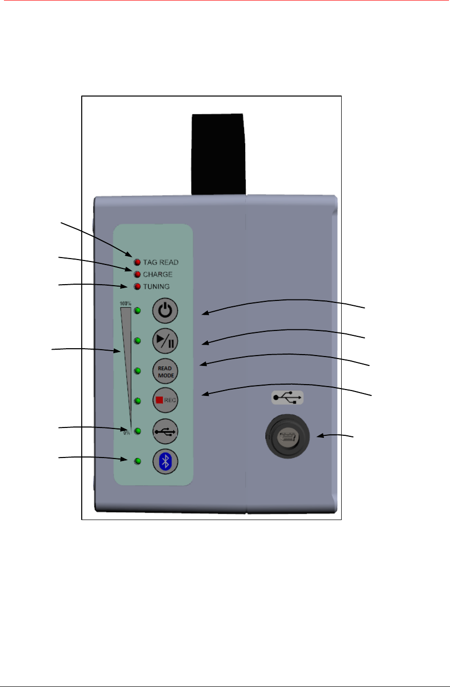
1.1 Front overview
Tag Read
status LED
Battery charge
status LED
Tuning
status LED
Battery
level bar
REC button
and status LED
miniUSB connector
Mode button
and status LED
Play/Pause button
and status LED
ON button
and status LED
USB mode
button and
status LED
Bluetooth
button and
status LED
WALK BY
Walk By Stationary Reader 5
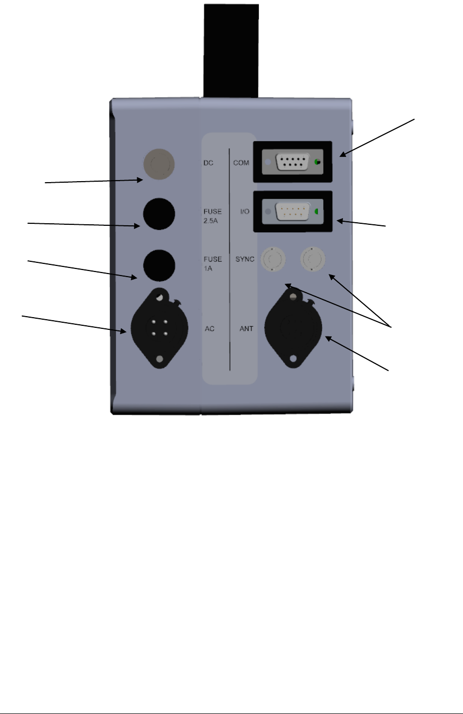
1.2 Back overview
Power AC
connector
RS232 connector
Inputs/Outputs
connector
Antenna connector
Sync connectors
(not to be used)
AC fuse
DC fuse
DC connector

Walk By Stationary Reader 6
2 How to set up the system
In order to correctly set-up the reader and have it ready for use, please follow the following
instructions:
Mount the WALK BY at intake, at the weigh station, at the entry to the main play area,
wherever it makes the most sense in your facility.
Connect the Gate antenna to the reader unit (plug the cable into the Antenna connector,
shown in the back overview picture above).
Connect the WALK BY reading unit to the electrical power supply (just plug one end of the
cable into the Power AC Connector, and the other end to the wall socket).
You can alternatively use the internal battery of the reader (in this case 4 hours of continuous
reading are guaranteed).
Connect the external display to the reader unit via the serial RS232 connector (see back
overview picture).
Push the Power On button to start operating the reader. The display automatically switches on
together with the reader. At switching on, the reader always starts operating in continuous
mode and working in Virtual Com Port.
Walk By Stationary Reader 7
3 User interface
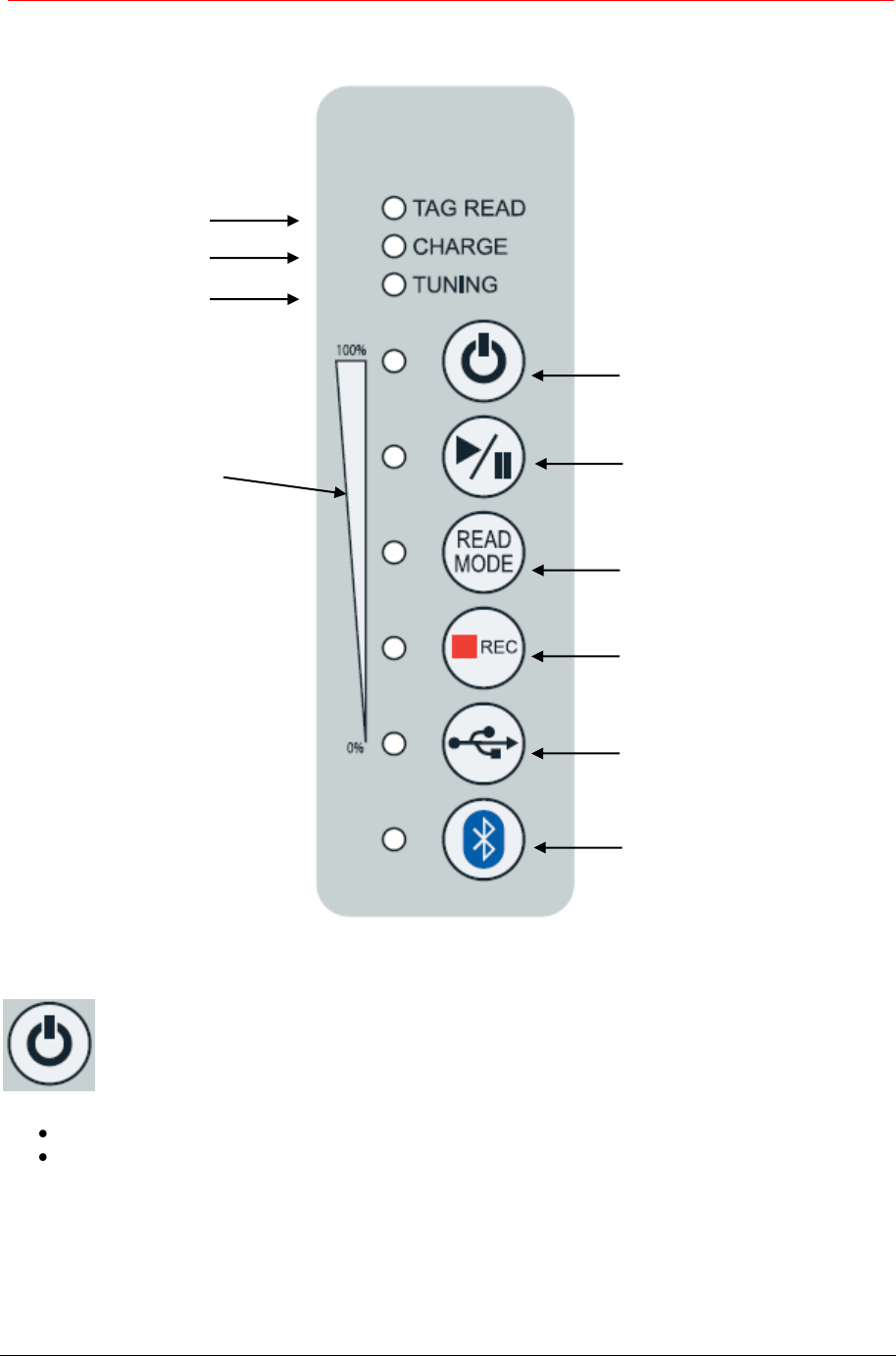
3.1 Keypad
3.2 ON button
The Power ON button is used to switch on or switch off the reader.
Press the ON button to power up the reader.
Hold the ON button for more than two seconds to power off the reader.
Through the configuration file, the WALK BY reader can be set up in order to automatically switch off
after a predefined time of inactivity (1 min, 5 min, 10 min, no auto shutdown time), when in Pause
mode. If it is in reading mode (Play/Pause button LED is green), the reader never automatically
switches off.
Tag Read status LED
Battery charge status LED
Tuning status LED
ON button and status LED
Play/Pause button and status LED
Mode button and status LED
Rec Button and status LED
USB Mode Button Led
Bluetooth button and status LED
Battery level bar
Walk By Stationary Reader 8
3.3 Battery level bar
The battery status displays the battery level.
When switching on, the reader shows the battery level for 3 seconds.
In order to see the battery level while the reader is on, put first the reader in Pause mode (Pause
button LED is off), and then click on the ON button briefly: 5 LEDs lit correspond to 80/100% charge
level, no LED lit corresponds to 0/20% level.
3.4 PLAY/PAUSE button
When switching on, the reader automatically goes in reading mode.
The Play/Pause button allows starting and stopping a reading session:
When the LED is on/green, the device is reading.
When the LED is off the device is in Pause.
If the LED is blinking the device is in Power Save mode.
N.B. Play/Pause button is a critical button to allow the reader performing various actions.
It is in fact necessary that the reader is always put first in Pause mode (LED is off) to be able to:
Change reading mode
Start/stop recording
Change USB set-up
Enable/Disable Bluetooth
Trigger the autotuning
Once one of the above selections has been made, push again the Play button to let the scanner
reading again.
3.5 READ MODE button
The READ MODE button allows selecting the reading mode.
There are three different options: continuous (LED Green), buffered (LED Yellow) and single read
mode (LED Off).
Walk By Stationary Reader 9
3.5.1 Continuous mode
LED Green: When continuous mode is selected, the device reads continuously and keeps
displaying the ID codes of the microchips read. The unit will display the same microchip number
repeatedly if the same microchip is scanned continuously.
3.5.2 Buffered mode
LED Yellow: When buffered reading mode is selected, the reader reads continuously, but inhibits
the duplicate display of the same microchip code. The reader will display the ID code only the first
time the microchip is read. The device does not display (nor record, if recording is enabled) any
new ID codes until another microchip is read.
The buffer size is 16 elements.
3.5.3 Single mode
LED off: When the single read mode is selected, the device reads for a default amount of
configurable time (max 240s). If a microchip is found during the allotted time, the reader shows its
ID code and stops reading. If no microchip is found during the allotted time, the reader stops the
reading session and shows the message TAG NOT FOUND.
3.6 Status LEDS
3.6.1 Tag Read LED
When the Tag Read LED is lit, the device is reading a transponder.
3.6.2 Charge LED
The Charge LED is lit when the reader is charging the battery.
If the LED blinks while the reader is running in battery mode, it means that the battery is low and
need to be charged.
If the LED blinks while the reader is connected to a power supply either AC or DC, a charge error
occurred (temperature out of range or DC IN voltage is too low).
3.6.3 Tuning LED
The Tuning LED shows the status of the tuning of the antenna connected to the device.
If the LED is green: the antenna tuning is ok.
If the LED is blinking green: a noise (FDX channel) is detected; once run the procedure for the
autotuning, the antenna can be perfectly tuned but still, it might detect some external noise.
If the LED is red (only in PAUSE mode): the antenna is not correctly tuned.
3.7 Autotuning
This operation is useful to optimize the reading performance of the antenna, especially in presence of
metals. The autotuning is automatically done at switching on of the reader.
The autotuning of the antenna can be performed by holding down the Play/Pause button for 2
seconds. Once the autotuning is done (tuning LED becomes green), the reader makes two short
beeps.
It is recommended to do the autotuning of the antenna when moving the antenna to a different
position and the tuning LED becomes red. This action is also recommended when passing from AC
electrical supply to DC electrical supply.
Walk By Stationary Reader 10
3.8 REC button
By pressing the REC button, you enable or disable the recording on a file of the microchips
read.
When the LED is on/red the recording is enabled.
When the LED is off the recording is disabled.
When a file is created, its name is automatically generated by the reader and saved in the following
folder: \data\<current year>\<current month>\s< ddmmyyyy_hhmmss>.rfid
For example, S08052013183448 means that a reading session was run on the 8th of May 2013, at
18:34:48.
Each file is saved with the following structure:
DATE,TIME,TAG
20130508,183505,999000000015420
20130508,192211,999000000015421
20130508,195416,999000000015422
Empty files are automatically erased by the reader.
3.9 USB Mode Button
The USB Mode button allows selecting how to use the Mini USB with a PC Host. There are
three different options:
Mass Storage (LED Off)
Virtual Com Port (LED Green)
Keyboard Wedge (LED Red)
To change the USB mode, you need first to put the reader in Pause mode, by pushing the Pause
mode button and then disconnect the USB cable from the PC. Once the new USB mode is selected,
connect again the reader via the USB cable.
3.9.1 Mass Storage
LED Off: When mass storage is selected, the reader behaves like a USB stick. You can review
the contents of the internal reader SD card. You can download or upload files to the reader’s SD
card.
The reader cannot be used to scan microchip while files are being transferred.
N. B. Do not delete the files already on the SD-Card of the reader. You can only work on/delete
data in the “data” folder.
3.9.2 Virtual Com Port
LED Green: When Virtual Com Port is selected, you can send and get data through the USB port
as though it were a serial/RS232 port.
When using it the first time, it is necessary to install the VCP driver on your Windows pc. You can
find it in the SD card of the reader, accessible via Mass Storage. This operation is not needed if
you are using a Mac pc.
Walk By Stationary Reader 11
3.9.3 Keyboard Wedge
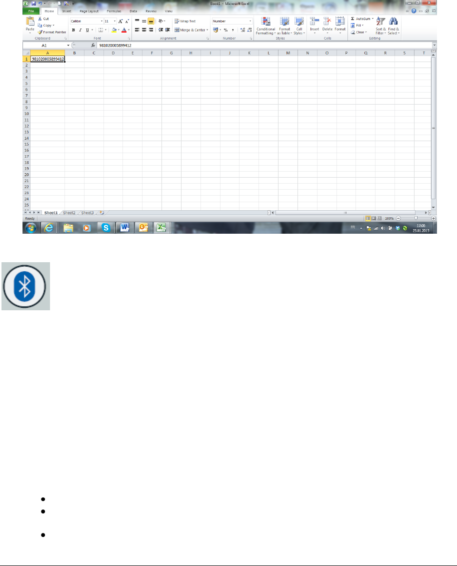
LED Red: In this mode, data is transferred from the WALK BY software via USB port to your
computer and data displayed as if entered by a keyboard. This might be helpful if you are using a
3rd party software application.
The more common applications that are used with such ‘keyboard wedges’ are Microsoft Excel,
Microsoft Access, and other database types of applications. They can be very helpful for filling in
a list of animals read or for quickly retrieving the information associated to that microchip number
in an animal database.
You just put the cursor where you want the ID code to go, and then you read the microchip and
automatically the microchip number pops in just as if you typed it on the keyboard (see below an
example made with Microsoft Excel).
3.10 BLUETOOTH button
Press the Bluetooth button to enable the wireless Bluetooth interface of the reader in order
to connect it to a PC.
The blue LED blinks until the connection to the PC is not established. When the connection between
PC and WALK BY is active the blue LED is lit continuously.
In order to disable the wireless Bluetooth interface press the Bluetooth button again.
3.10.1 Configure the WALK BY for the Bluetooth connection
During the Bluetooth discovery process done by the PC, it is important that the WALK BY reader
is ON and the Bluetooth LED blinks.
To use the Bluetooth on your PC, you can refer to Windows or MAC instructions for a standard
pairing Bluetooth configuration, depending on the operative system you have on your PC.
Main steps:
Be sure the computer is equipped with Bluetooth hardware too.
Add the WALK BY Bluetooth device, once verified that the WALK BY reader is switched
on and the Bluetooth is enabled.
Don’t forget to use as passkey/pairing code the number zero (just one 0 character).
Walk By Stationary Reader 12
Once the WALK BY reader has been recognized and installed on your PC as a Bluetooth
device, a new port COM is added to your PC.
Select this port COM from any program which is supposed to communicate to the reader.
In order to test the port COM, a HyperTerminal session (in Windows) can be opened.
Please verify on your WALK BY that the Bluetooth LED is lit continuously.
3.11 Real-time communication
To open an RS232 terminal session (eg. Hyperterminal, TeraTerm or custom application), once
connected via Bluetooth, you can refer to Windows or MAC instructions of the terminal session you
are working with. Make sure to select the right COM port assigned to the Bluetooth.
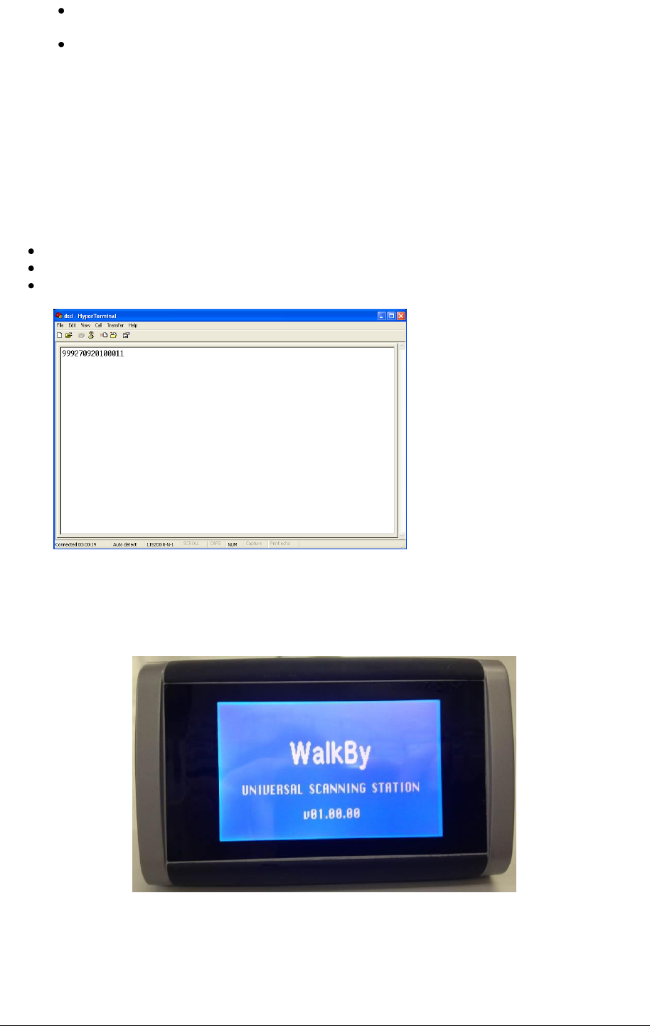
For example, on Hyperterminal, after having selected the assigned COM port, Hyperterminal is ready
to start and just click on the calling icon or select Call under the Call menu.
At this point you are ready to receive the codes read directly on your PC.
Press Play/Pause button and read a transponder.
The ID code will be shown on the HyperTerminal window like in the following picture:
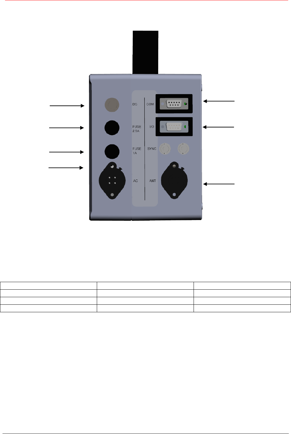
3.12 External display
The external display is automatically switched on when powering up the reader.
If the display is not connected when switching on the reader, the connector can be used as a normal
RS232 COM port to allow serial connection, once set it up this way through the configuration file.
Walk By Stationary Reader 13
4 Connectors
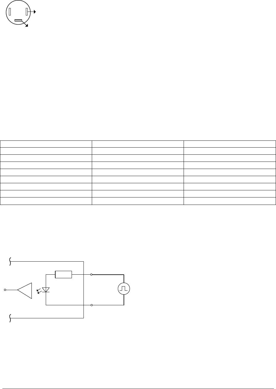
All the reader’s connectors are on the back as shown in the picture below:
4.1 Power AC input
The F310 can be connected to the Power line AC either 110V/60Hz or 220V/50Hz.
The cable is connected as follows:
Pin
Cable color
Description
1
Brown
L
3
Blue
N
GND
Yellow/green
GND
4.1.1 AC Fuse
The AC fuse has the following specifications:
Fusible 5 x 20 mm, 1 A, 250 VAC, Time-lag
Power AC input
AC Fuse
Power DC input
DC Fuse
Antenna
I/O
Serial COM
interface
Walk By Stationary Reader 14
4.2 Power DC input
The reader can be powered also with DC from 12 to 14V.
The DC connector is cabled ad follows (bottom view):
Red wire
Black wire
Note: remember to
insert the heatshrink
on the wires before
soldering
4.2.1 DC Fuse
The DC fuse has the following specifications:
Fusible 5 x 20 mm, 2.5 A, 250 VAC, Time-lag
4.3 Antenna
The antenna is connected between pin2 and pin GND of the antenna connector.
4.4 I/O
Signal
Description
DSUB pin
+ IN1
Positive input 1 terminal
1
- IN1
Negative input 1 terminal
2
+ IN2
Positive input 2 terminal
4
- IN2
Negative input 2 terminal
5
+ OUT1
Positive output 1 terminal
6
- OUT1
Negative output 1 terminal
7
+ OUT2
Positive output 2 terminal
8
- OUT2
Negative output 2 terminal
9
The Input and Output 2 have to be set using the commands .RIN and .SOUT (see chapters 4.2.15 and
4.2.16). The Input 1 and Output 1 are ready to respond without any further command.
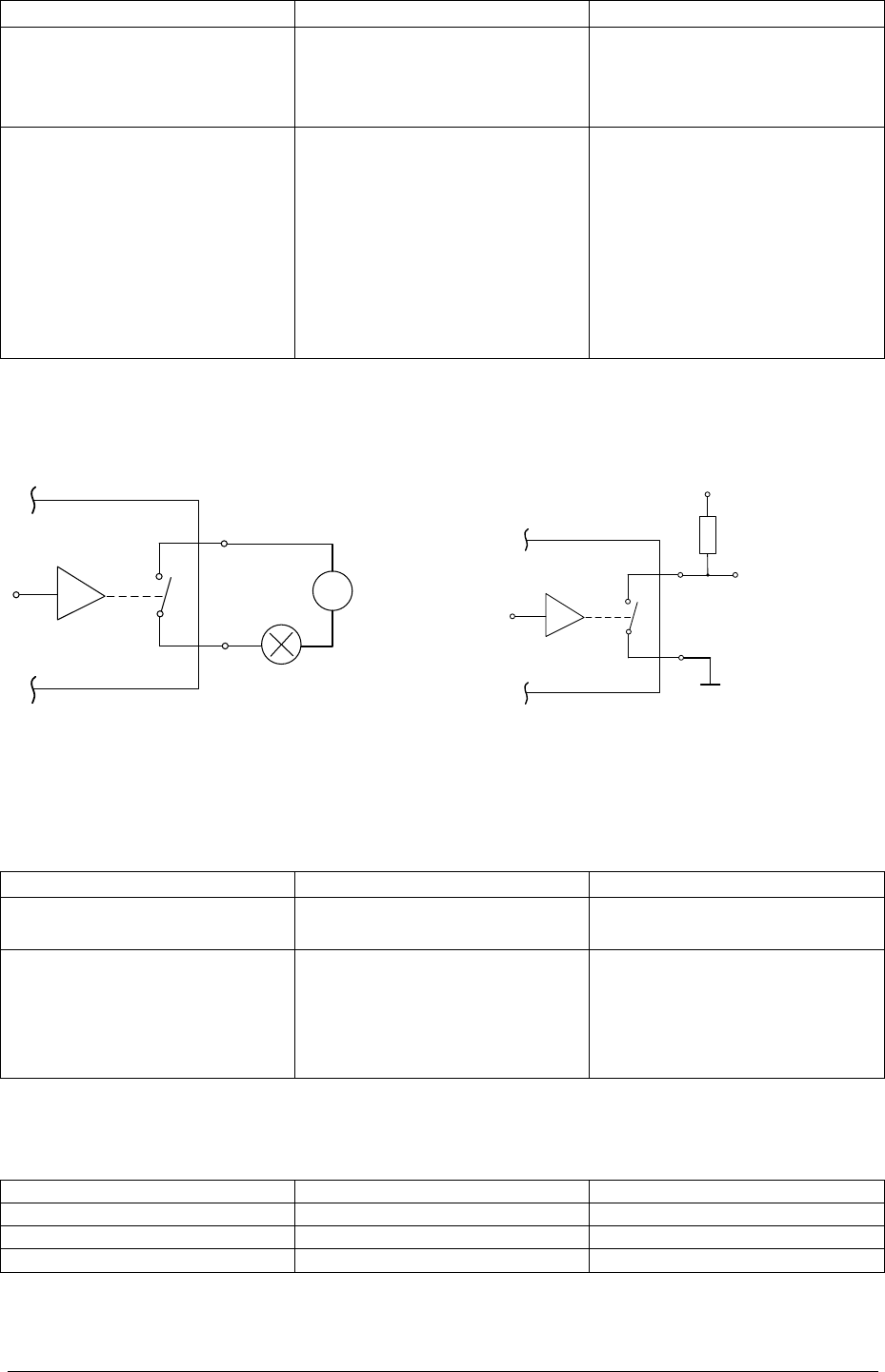
4.4.1 Input
Example of connection for the Input:
R+ IN
- IN
5...24VDC
MIN Uin 5V
MAX Uin 24VDC
MIN Iin 3mA
MAX Iin 10mA
Input functions:
Walk By Stationary Reader 15
GPIO
Main function
Seconadry function
INPUT TRIGGER (1)
Start a single reading session.
The reading session time can be
programmed by user.
This input can weak up the
device when it is switched off.
INPUT AUX (2)
This auxiliary input can be read
by the USER through a serial
command.
.RINA (read the input aux
command)
INA =1 (when the input is
active)
INA=0 (when the input is not
active)
This input can weak up the
device when it is switched off.
4.4.2 Output
Examples of connection for the Outputs:
+ OUT
- OUT
0...24V @ 1A
VDC
LAMP
+ OUT
- OUT
to MCU
10KΩ
VCC
MAX Uout 24VDC
MIN Uout 0VDC
MAX Iout 1.0A
Output functions:
GPIO
Main function
Seconadry function
OUTPUT TAG READ (1)
This output is activated when a
tag is read.
none
OUTPUT AUX (2)
This auxiliary output can be
written by the USER though a
serial command
.SETOUTA 10 (activate the
output aux during 1.0 sec)
none
4.5 Serial COM interface
The Serial COM interface is connected as follows:
Pin
Cable color
Description
2
Orange
RX
3
Red
TX
5
Brown
GND

Walk By Stationary Reader 16
5 Command interface
5.1 Command overview
The user can send and get data from the XTEND MAX, either via VCP, Bluetooth connection.
Three different kinds of commands are possible:
o Get
o Set
o Execute
A Get command is used to read a parameter value from the reader and always starts with the
question mark symbol “?”, e.g “?<CMD>\r\n”.
A Set command is used to change a parameter value into the reader and always starts with a dot “.”,
followed by the command name and parameter value, e.g “.[CMD]<par>\r\n”.
An Execute command is sent to the reader to perform an action, these commands always start with
“.”, and don’t not have any parameters, e.g. “.<CMD>\r\n”.
The following table summarizes the Walk By commands which were present in the old version of the
reader:
CMD
Description New commands
Parameter
Range
.?
Help, shows all commands
.v
Get the reader version
.T
Save acquired signal
.GB
Get the battery level
.r
Start / Stop single read
.YE
Set the date year
.YExx
00 – 99
.MO
Set the date month
.MOxx
01 – 12
.DA
Set the date day
.DAxx
01 – 31
.DF
Set the date format [ 0=EU; 1=US ]
.DFx
0 – 1
?DF
Get the date format
?DT
Get the current date
.HO
Set the time hour
.HOxx
00 – 23
.MI
Set the time minutes
.MIxx
00 – 59
.SE
Set the time second
.SExx
00 – 59
?TM
Get the current time
.DM
Set output tag format [ 0=Long; 1=Short ]
.DMx
0 – 1
?DM
Get output tag format
.SM
Store in session file [ 0=Disable; 1=Enable ]
.SMx
0 – 1
?SM
Get store in session file
.RS
Set reading sound [ 0=Disable; 1=Enable ]
.RS
0 – 1
?RS
Get reading sound status
.RT
Set the reading timeout [ Second ]
.RTxxx
001 – 240
?RT
Get the reading timeout
.PB1
Press KEYON button
.PB2
Press PLAY button
.PB3
Press MODE button
.PB4
Press REC button
.PB5
Press USB button
.PB6
Press Bluetooth button
.RC
Start / Stop continuous reading
.RB
Start / Stop buffered continuous reading
.CB
Clear reader buffer
.SB
Show reading buffer
.ANTG
Start autotuning

Walk By Stationary Reader 17
.RIN
Read I/O input 2
.SOUT
Set I/O output 2 [ Time = xx * 100 ms ]
.SOUTxx
01 – 50
.PS
Enable power save mode
.RM
Set reading mode
[ 0=Single; 1=Buffered; 2=Continuous ]
.RMx
0 – 2
?RM
Get reading mode
.STAT
Start statistic test
.DIAG
Set diagnostic level
[ 0=None; 1=Error; 2=Info; 3=Debug ]
.DIAGx
0 – 3
?DIAG
Get diagnostic level
?TB
Get tuning level FDX-B
?TA
Get tuning level FDX-A
?TN
Get tuning level TVN
?NFB
Get noise floor NFB
5.2 Command description
All commands, available only on the Walk By scanning station, start with a ‘.’ (dot) or with a question
mark followed by the command name, and eventually an integer parameter, and end with a carriage
return character ([CR]=13 dec).
.CMD<PARAM> or ?CMD
5.2.1 Command: .?
It returns the list with all commands available:
.?
------------------------ Command Line Help ------------------------
00] .? -> Help
01] .v -> Get reader version
02] .T -> Save acquired signal
03] .GB -> Get Battery Level
04] .r -> Start/stop single read
05] .YE -> Set the date year (.YExx)
06] .MO -> Set the date month (.MOxx)
07] .DA -> Set the date day (.DAxx)
08] .DF -> Set date format: .DFx [0 EU] [1 US] )
09] ?DF -> Get date format
10] ?DT -> Get current Date
11] .HO -> Set the time hour (.HOxx)
12] .MI -> Set the time minutes (.MIxx)
13] .SE -> Set the time seconds (.SExx)
14] ?TM -> GetCurrent Time
15] .DM -> Set output tag format: .DMx [0 Long], [1 Short]
16] ?DM -> Get output tag format
17] .SM -> Store in session file: .SMx [0 disable], [1 enable]
18] ?SM -> Get Store in session file
19] .RS -> Set Reading Sound: .RSx [0 disable], [1 enable]
20] ?RS -> Get Reading Sound Status
21] .RT -> Set the reading timeout[s]: (.RTxxx)
22] ?RT -> Get the reading timeout
23] .PB1 -> Press KEYON button
24] .PB2 -> Press PLAY button
25] .PB3 -> Press MODE button
26] .PB4 -> Press REC button
27] .PB5 -> Press USB button
28] .PB6 -> Press Bluetooth button
29] .RC -> Start/Stop Continuous Reading
30] .RB -> Start/Stop Buffered Continuous Reading
31] .CB -> Clear reader buffer

Walk By Stationary Reader 18
32] .SB -> Show Reading buffer
33] .ATNG -> Start autotuning
34] .RIN -> Read I/O Input 2
35] .SOUT -> Set I/O Output 2, for <time> [1-50] in 100*1ms
36] .PS -> Enable Power Save mode
37] .RM -> Set Reading Mode: .RMx [0 Single], [1 Buffered], [2 Continuous]
38] ?RM -> Get Reading Mode
39] .STAT -> Start Statistic Test
40] .DIAG -> Set diagnostic level: .DIAGx [0 none], [1 error], [2 info], [3 debug]
41] ?DIAG -> Get Diagnostic level
42] ?TB -> Get Tuning Level FDXB
43] ?TA -> Get Tuning Level FDXA
44] ?TN -> Get Tuning Level TVN
45] ?NFB -> Get Noise Floor NFB
-------------------------------------------------------------------
5.2.2 Command: .v
It returns the firmware version:
.v
WALKBY RFID READER v1.0.0
5.2.3 Command: .T
It saves acquired signals in to the SD-Card:
.T
Created 0:/sys/log/rfid/BAT_000001.rfl
Created 0:/sys/log/rfid/FDXB_000001.rfl
Created 0:/sys/log/rfid/FDXB_000001.rfl
Created 0:/sys/log/rfid/FDXA_000001.rfl
Created 0:/sys/log/rfid/FDXA_000001.rfl
Created 0:/sys/log/rfid/TVN_000001.rfl
Created 0:/sys/log/rfid/TVN_000001.rfl
Created 0:/sys/log/rfid/AVID_000001.rfl
Created 0:/sys/log/rfid/AVID_000001.rfl
Created 0:/sys/log/rfid/FDXB_000001.rfl
5.2.4 Command: .GB
It gets the battery level, this command work only when the scanning station is in battery mode:
.GB
BATTERY: 2526
5.2.5 Command: .r
It starts or stops a single reading session, when a tag is in to the read range of the antenna you can
see the UID as response:
.r
999000000000001
5.2.6 Command: .YE
It sets the date year, after the command you have to write the last two digit of the current year. You do
not receive an answer:
.YE13

Walk By Stationary Reader 19
5.2.7 Command: .MO
It sets the date month, after the command you have to write the two digit of the current month. You do
not receive an answer:
.MO07
5.2.8 Command: .DA
It sets the date day, after the command you have to write the two digit of the current day. You do not
receive an answer:
.DA29
5.2.9 Command: .DF
It sets the date format, after the command you have to write the 0 “zero” for the EU format
(dd.mm.yyyy) or the 1 ”one” for the US format (mm.dd.yyyy). You do not receive an answer:
.DF0
5.2.10 Command: ?DF
It gets the date format:
?DF
DF=0 [0 EU] [1 US]
5.2.11 Command: ?DT
It gets the current date:
?DT
DT=29.07.2013
5.2.12 Command: .HO
It sets the time hours, after the command you have to write the two digit of the current hour. You do
not receive an answer:
.HO16
5.2.13 Command: .MI
It sets the time minutes, after the command you have to write the two digit of the current minute. You
do not receive an answer:
.MI55
5.2.14 Command: .SE
It sets the time seconds, after the command you have to write the two digits of the current second.
You do not receive an answer:
.SE35
5.2.15 Command: ?TM
It gets the current time (Format: hh.mm.ss):
?TM
TM=16.55.45

Walk By Stationary Reader 20
5.2.16 Command: .DM
It sets the output format of the tag, after the command you have to write the 0 “zero” for the long
format (A00000999000000000001) or the 1 ”one” for the short format (999000000000000001). You do
not receive an answer:
.DM1
5.2.17 Command: ?DM
It gets the output format of the tag:
?DM
DM=1 [0 Long] [1 Short]
5.2.18 Command: .SM
It sets if the read tag has to store or not in the session file, after the command you have to write the 0
“zero” for disable or the 1 ”one” for enable the storage of the read UID. You do not receive an answer:
.SM0
5.2.19 Command: ?SM
It gets the status of the store mode:
?SM
SM=0 [0 Disable] [1 Enable]
5.2.20 Command: .RS
It sets if the reading sound has to be on or off, after the command you have to write the 0 “zero” for
disable or the 1 ”one” for enable the reading sound during the reading session. You do not receive an
answer:
.RS0
5.2.21 Command: ?RS
It gets the status of the store mode:
?RS
RS=0 [0 Disable] [1 Enable]
5.2.22 Command: .RS
It sets the reading time for the single read mode, after the command you have to write three digits
from 001 to 240 (reading time = xxx * 1 second). You do not receive an answer:
.RT099
5.2.23 Command: ?RS
It gets the reading time:
?RT
RS=99
5.2.24 Command: .PBx (from 1 to 6)
It emulates the pressing of a button from the keypad. You do not receive an answer:
.PB1: Press KEYON button
.PB2: Press PLAY button

Walk By Stationary Reader 21
.PB3: Press MODE button
.PB4: Press REC button
.PB5: Press USB button
.PB6: Press Bluetooth button
5.2.25 Command: .RC
It starts or stops a continuous reading session, when a tag is in to the read range of the antenna you
can see the UID as response, and the visualization of a tag that stay in the read range is every
successful read:
.RC
999000000000001
999000000000001
999000000000001
999000000000001
5.2.26 Command: .RB
It starts or stops a buffered continuous reading session, when a tag is in to the read range of the
antenna you can see the UID as response, and the visualization of a tag that stay in the read range is
only once. The reader continuous too read the tag, but it put the tag only once on the screen:
.RB
999000000000001
5.2.27 Command: .CB
It cleans the content of the buffer. You do not receive an answer:
.CB
5.2.28 Command: .SB
It gets the content of the buffer:
.CB
00] 999000000000001
01] --empty--
02] --empty--
03] --empty--
04] --empty--
05] --empty--
06] --empty--
07] --empty--
08] --empty--
09] --empty--
10] --empty--
11] --empty--
12] --empty--
13] --empty--
14] --empty--
15] --empty—
5.2.29 Command: .ATNG
It starts the antenna autotuning:
.ATNG
ATNG FDXB: pos=16, val=34
ATNG FDXA: pos=0, val=28
ATNG TVN : pos=2, val=30

Walk By Stationary Reader 22
5.2.30 Command: .RIN
It reads I/O Input 2 value. Active low:
.RIN
1
5.2.31 Command: .SOUT
It sets the I/O Output 2 value, after the command you have to write two digits from 01 to 50 (active
high = xx * 100 ms). You do not receive an answer:
.SOUT10
5.2.32 Command: .PS
It sets if the power save mode has to be on or off, after the command you have to write the 0 “zero” for
disable or the 1 ”one” for enable the power save mode. You do not receive an answer:
.PS0
5.2.33 Command: .RM
It sets the reading mode, after the command you have to write the 0 “zero” for the single mode, the 1
”one” for the buffered continuous mode or the 2 “two” for the continuous mode. You do not receive an
answer:
.RM1
5.2.34 Command: ?RM
It gets the reading mode setting:
?RM
RM=1 [0 Single] [1 Buffered] [2 Continuous]
5.2.35 Command: .STAT
It starts the statistic test:
.STAT
Statistic Test Started...
FDXA RATE 100 - 100 -> 100
FDXB RATE 050 - 100 -> 050
TVN RATE 099 - 099 -> 099
HDX RATE 397 - 397 -> 100
AVID RATE 099 - 099 -> 100
5.2.36 Command: .DIAG
It sets the diagnostic mode, after the command you have to write the 0 “zero” for no diagnostic, the 1
”one” for the readers information, the 2 “two” for the readers errors or the 3 “three” for the debug. You
do not receive an answer:
.DIAG0
5.2.37 Command: ?DIAG
It gets the status of the diagnostic mode:
?DIAG
Diagnostic Level=0 [0 NONE] [1 ERROR] [2 INFO] [3 DEBUG]

Walk By Stationary Reader 23
5.2.38 Command: ?TB
It gets the tuning level of the FDX-B channel:
?TB
28B
5.2.39 Command: ?TA
It gets the tuning level of the FDX-B channel:
?TA
29A
5.2.40 Command: ?TN
It gets the tuning level of the FDX-B channel:
?TN
30N
5.2.41 Command: ?NFB
It gets the noise level:
?NFB
27FB

Walk By Stationary Reader 24
6 Do You Have A Problem Identifying An Animal?
6.1 The reading distance is too short
The maximum reading distance is obtained with the transponder (tag) perpendicular to the antenna
and aimed at the center of the antenna coil. If the tag is implanted into an animal, its orientation may
not be optimal and therefore the reading distance may be reduced.
You might be close to a source of electromagnetic disturbances like video or TV. Move a few meters
away and try again.
Do not use the reader on a steel table. The metal will reduce the performance of the antenna.
The reading distance is reduced if the transponder is still in the needle.
6.2 The reader does not read the transponder
Some types of transponders from other manufacturers are disturbed if placed in the center of the
reader-antenna. It is possible that some tags will not function if placed in parallel and at the center of
the antenna. Change the direction of the tag or of the antenna.
Change the position of the microchipped animal and try again.
6.3 The reader does not work
Check the ambient temperature: it has to be between 0ºC and +50º C.
If you’re still having problems, please contact your dealer.
The XTEND MAX reader is a product developed and produced by DATAMARS.
Should you have any suggestions or require information regarding this or other DATAMARS products,
please contact your dealer

Walk By Stationary Reader 25
7 Certification
Datamars SA, Via ai Prati, CH-6930 Bedano declares, under its own responsibility, that the product
WALK BY scanning station is in accordance with the following standards:
FCC Part 15B Part 15 Class B Computing Device Peripheral
FCC Part 15C Part 15 Low Power Transmitter Below 1705 kHz
This device complies with Part 15 of the FCC Rules. Operation is subject to the following two
conditions: (1) This device may not cause harmful interference, and (2) This device must accept any
interference received, including interference that may cause undesired operation.
This equipment has been tested and found to comply with the limits for Class B Digital Device,
pursuant to Part 15 of the FCC Rules. These limits are designed to provide reasonable protection
against harmful interference in a residential installation. This equipment generates and can radiate
radio frequency energy and, if not installed and used in accordance with the instructions, may cause
harmful interference to radio communications. However, there is no guarantee that interference will
not occur in a particular installation. If this equipment does cause harmful interference to radio or
television reception, which can be determined by turning the equipment off and on, the user is
encouraged to try to correct the interference by one or more of the following measures.
o Reorient or relocate the receiving antenna
o Increase the separation between the equipment and receiver
o Connect the equipment into an outlet on a circuit different from that to which the receiver is
connected
o Consult the dealer or an experienced radio/TV technician for help
Any changes or modifications not expressly approved by the party responsible for compliance could
void the user’s authority to operate the equipment.

Walk By Stationary Reader 26
8 Specification
1. Storage temperature: -20°C to +65°C, 85% RH, non-condensing
2. Normal operating temperature: -5°C to +55°C, 85% RH, non-condensing
3. Charging temperature: +5°C to +40°C, 85% RH, non-condensing
4. Housing material: PC/ABS
5. Protection Level: Water resistant
6. Power supply: Li-Ion integrated battery pack
7. Battery life: >500 cycles.
8. Battery charging time: 3h
9. Continuous reading time: 4h. Up to 6h in Power Save mode (60 sec timeout)
10. Power supply (battery charger): 110/240VAC and/or 12-14VDC
11. ID code storage capacity: > 2 million ID records
12. Dimensions: 250mm (W) x 170mm (H) x 125mm (D)
13. Weight of the reader: 2060 g
14. Tag compatibility: FDX-B, FDX-A, Avid encrypted, Trovan
15. Transmission frequency: 134.2 kHz
16. Interfaces to host PC: USB (Mass Storage, Virtual Com Port, Keyboard Wedge), RS-232 and
Bluetooth.
17. Typical reading distance:
FDX-B: Up to 45 cm
FDX-A: Up to 30 cm
AVID: Up to 31 cm
Trovan FDX-B: Up to 45 cm
Trovan FDX-A: Near the antenna
18. Additional external antenna: Gate Antenna
19. Standards: ISO 11784/5
Walk By Stationary Reader 27
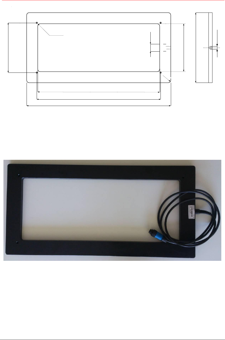
9 Antenna
M16 x 1.5
40.0
780.0
660.0
260.0
380.0
R 14
670.0
270.0
4x Ø8.0
Material: HMWPE (High Molecular Weight Polyethylene) blue
Dimension: 380mm (L) x 780mm (H) x 20mm (P)
Weight: 3.5kg
Cable length: 2.50m