Datamatic D4300 Spread Spectrum TX User Manual USER MANUAL May0108
Datamatic, Ltd Spread Spectrum TX USER MANUAL May0108
Users Manual

©Datamtic, Ltd. 2000-2008
FIREFLY® – Energy 2.8
FIREFLY® AMR SYSTEM REFERENCE MANUAL
3600 K Avenue
Plano,TX 75074
24-Hour Customer Support
(888)-326-5032 or (214) 540-5200
Internet:http://www.datamatic.com
Email: csupport@datamatic.com

©
Datamatic, Ltd. 2000-2008 page
2

©
Datamatic, Ltd. 2000-2008 page
3

©
Datamatic, Ltd. 2000-2008 page
4
FIREFLY – ENERGY 2.8........................................................................................................................ 1
I
NTRODUCTION
....................................................................................................................................... 6
E
QUIPMENT
............................................................................................................................................. 7
Electric FIREFLY Installation Supplies.............................................................................................. 7
Electric Meter Install Kits ................................................................................................................... 8
FIREFLY
M
ENU
S
CREEN
...................................................................................................................... 9
R
EADING AN
E
LECTRIC
M
ETER
........................................................................................................... 10
I
NSTALLATION
P
ROCEDURES
............................................................................................................... 11
Electric FIREFLY Installation Procedures ....................................................................................... 11
FIREFLY Installation Procedures..................................................................................................... 11
Programming the Electric FIREFLY................................................................................................ 16
T
ROUBLESHOOTING
E
LECTRIC
FIREFLY
S
........................................................................................ 16
Before Leaving Office............................................................................................................................
Troubleshooting Field Procedure ..................................................................................................... 17
Troubleshooting Details .................................................................................................................... 17
Receiving no RF signal from a FIREFLY.......................................................................................... 17
Inaccurate Under-counting FIREFLY............................................................................................... 17
S
AMPLE
D
ATAMATIC
FIREFLY
R
EPORTS
......................................................................................... 18
Installed Report ................................................................................................................................. 18
Read and Verified Report .................................................................................................................. 19
Route Status Report ........................................................................................................................... 20

Regulatory Information
United States of America, FCC:
FCC ID: ODYD4300
This device complies with Part 15 of the FCC Rules. Operation is subject to the following two conditions;
(1) this device may not cause harmful interference, and
(2) this device must accept any interference received, including interference that may cause undesired operation.
Note: This equipment has been tested and found to comply with the limits for a Class B digital device, pursuant
to part 15 of the FCC Rules. These limits are designed to provide reasonable protection against harmful
interference in a residential installation. This equipment generates, uses and can radiate radio frequency energy
and, if not installed and used in accordance with the instructions, may cause harmful interference to radio
communications. However, there is no guarantee that interference will not occur in a particular installation. If
this equipment does cause harmful interference to radio or television reception, which can be determined by
turning the equipment off and on, the user is encouraged to try to correct the interference by one or more of the
following measures:
--Reorient or relocate the receiving antenna.
--Increase the separation between the equipment and receiver.
--Connect the equipment into an outlet on a circuit different from that to which the receiver is connected.
--Consult the dealer or an experienced radio/TV technician for help.
Caution: Changes or modifications not expressly approved by the manufacturer could void the user’s authority
to operate the equipment.
To comply with FCC RF exposure requirements, the device and the antenna for this device must be installed to
ensure a minimum separation distance of 20 cm or more from a person's body. Other operating configurations
should be avoided.
Canada, Industry Canada (IC)
The wireless radio of this device complies with RSS 210 Industry Canada. This Class B digital device complies
with Canadian ICES-003. The installer of this radio equipment must ensure that the antenna is located or
pointed such that it does not emit RF field in excess of Health Canada limits for the general population; consult
Safety Code 6, obtainable from Health Canada’s website www.hc-sc.gc.ca/rpb
©Datamatic, Ltd. 2000-2008 page 5

©Datamtic, Ltd. 2000-2008
Introduction
The FIREFLY AMR System is an automated meter reading system that collects meter reading data remotely and
wirelessly. This is accomplished using the Datamatic FIREFLY Meter Interface Unit that sends the radio signal to the
ROADRUNNER handheld receiver unit (walk-by) or the ROADRUNNER Mobile truck mounted receiver unit (drive-by)
or the Mesh Controller, Gateway.
The main benefits of using a wireless AMR system are:
• Increased speed of meter readings
• Increased accuracy of meter readings
• Safer meter reading procedure
After reviewing this training manual you should be able to perform the following functions:
• Install an electric FIREFLY
• Program an electric FIREFLY
• Set up and utilize all FIREFLY menu functions
• Read the FIREFLYs for billing
• Perform periodic audits and troubleshooting on FIREFLYs
©
Datamatic, Ltd. 2000-2008 page
7
Equipment
Electric FIREFLY Installation Supplies
Electric FIREFLY Installation Equipment
• 2-way RF ROADRUNNER.
• Phillips Screwdriver, #2 head, with 3-4” shaft. Used for attaching FIREFLY to meter.
• Flat Head Screwdriver, with
3
/
16
” wide head. Used for attaching FIREFLY power supply wire clips to meter’s utility
side power bus.
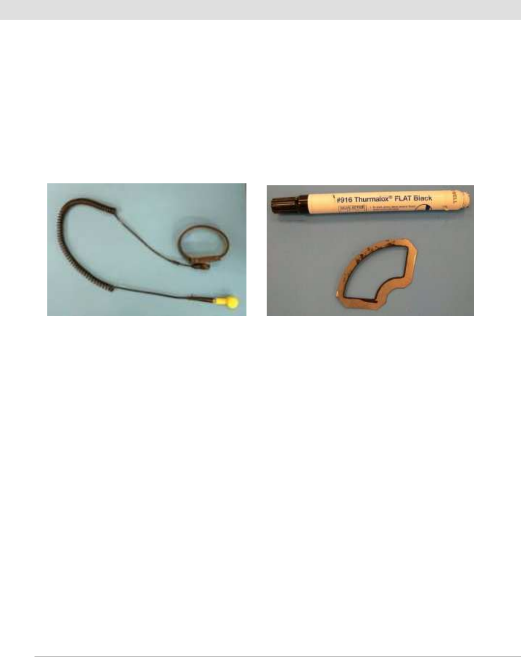
• Static grounding mat with wrist strap and grounding plug. Used whenever handling the electric FIREFLY by hand,
except when attached to meter.
Electric FIREFLY Installation Consumables
• Install packet including screws and nylon spacers.
• FIREFLY CR 2032 batteries.
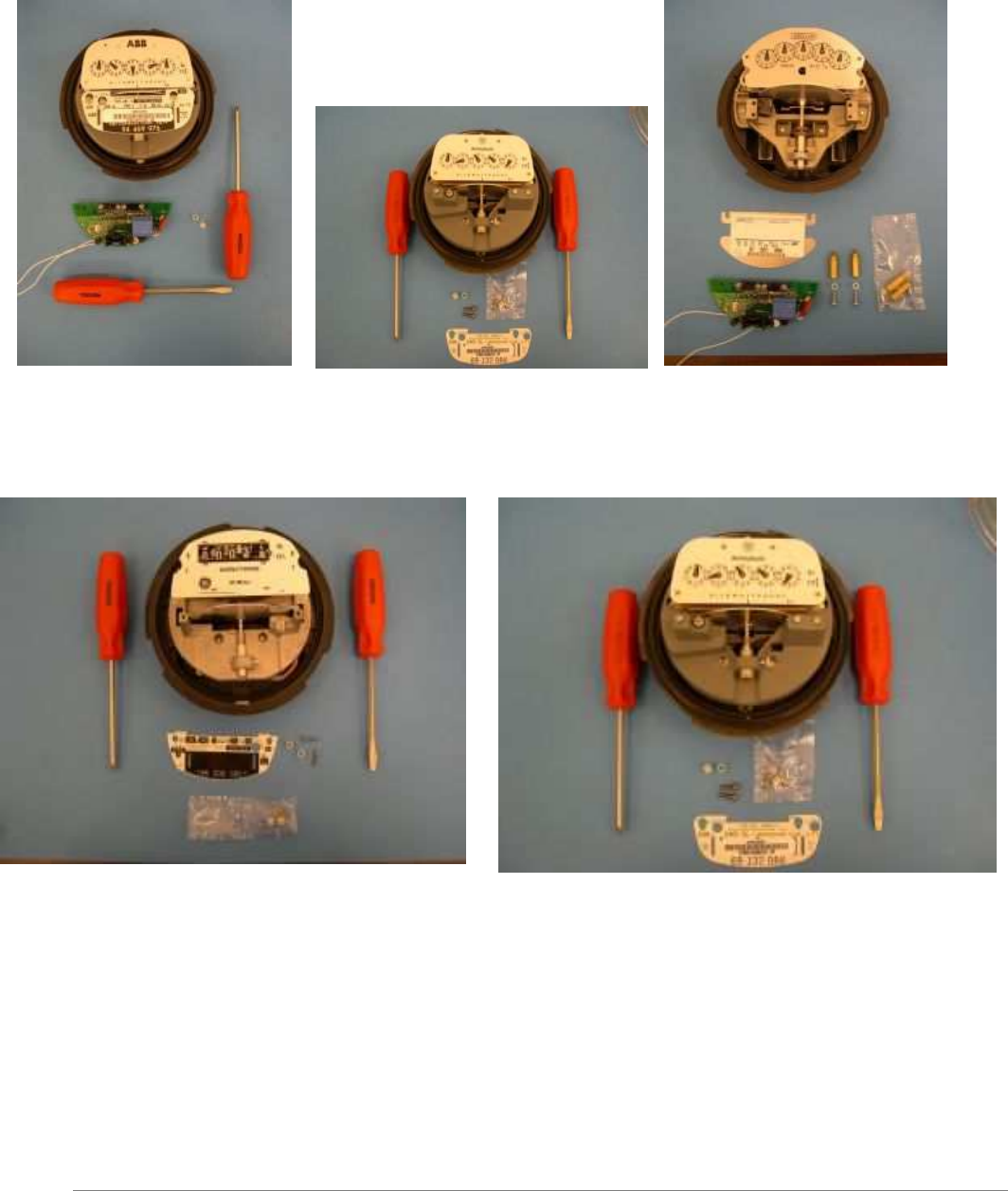
• Disc marking template.
• Datamatic Ltd.’s Part# D2311 paint marker. Used for painting meter disc. The warranty on the Electric FIREFLY will
NOT be honored if the Datamatic D2311 paint marker is not used on the meter disc.
©
Datamatic, Ltd. 2000-2008 page
8
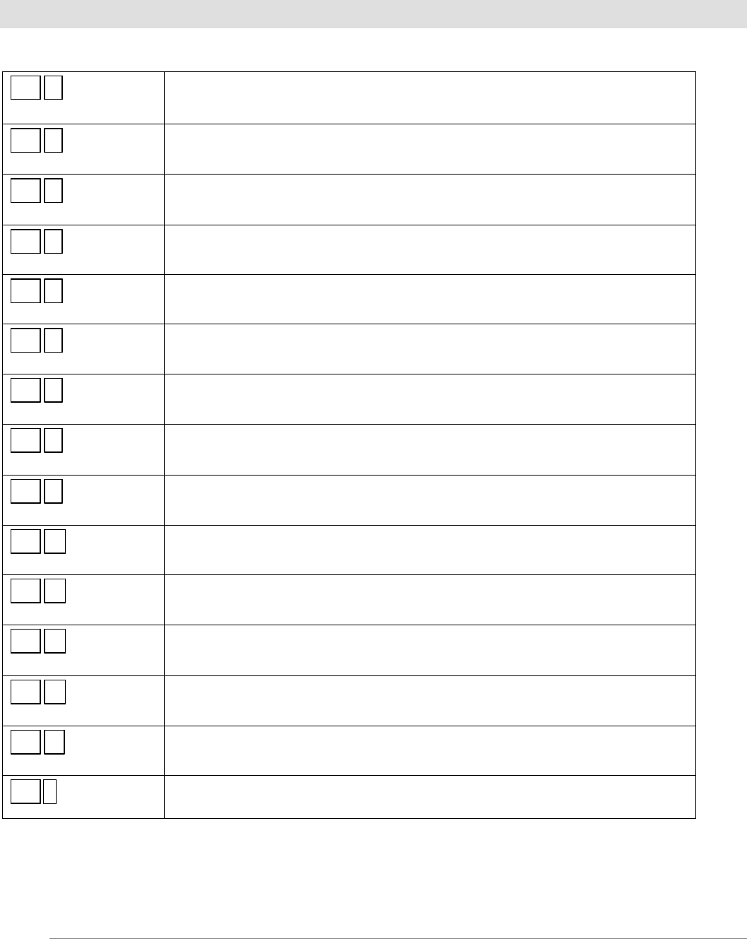
Electric Meter Install Kits
ABB Westinghouse Landis & Gyr
2 - .25 Nylon Spacers 2 - .25 Nylon Spacers 2 – 6-32 X ½” screws
2 – 6-40 X ½” screws 2 – Post Meter Spacers
2 - .25 Nylon Spacers
GE Sangamo
2 - .25 Nylon Spacers 2 - .25 Nylon Spacers
2 – 4-48X1/2” pan head screws
2 - 5-40X ½” screws
©
Datamatic, Ltd. 2000-2008 page
9
FIREFLY Menu Screen
Select the F5 key on the ROADRUNNER to access these options:
F5 1 Templates
(Use to set up the programming template)
F5 2 Program FF
(Use to program the FIREFLY)
F5 3 Program Indiv Param
(Use to reset individual programming parameters)
F5 4 Current Settings
(Allows the user to view all parameters of that FIREFLY)
F5 5 Profile Extract
(Extracts the FIREFLY’s consumption history)
F5 6 Set Reading Mode
(Use to set up how you want to read the FIREFLYs)
F5 7 Enter AutoCAL
(Use to activate AutoCAL mode for Water FIREFLYs)
F5 8 Exit AutoCAL
(Use to stop AutoCAL mode for Water FIREFLYs)
F5 9 Test RF Reception
(Test mode used at Datamatic, Ltd.)
F5 A Test Optics
(Use to check background values for Water FIREFLYs)
F5 B Diagnostics
(Use to check AutoCAL results for Water FIREFLYs)
F5 C Options
(Use to set options for the ROADRUNNER)
F5 D Capture Config
(To manually capture Configuration data at any time.)
F5 E AutoCAL Rules
(Use to set rules for the Water FIREFLY)
F5 F Clear Tamper
(Use to clear a tamper code on the Water FIREFLY)
©
Datamatic, Ltd. 2000-2008 page
10
Reading an Electric Meter
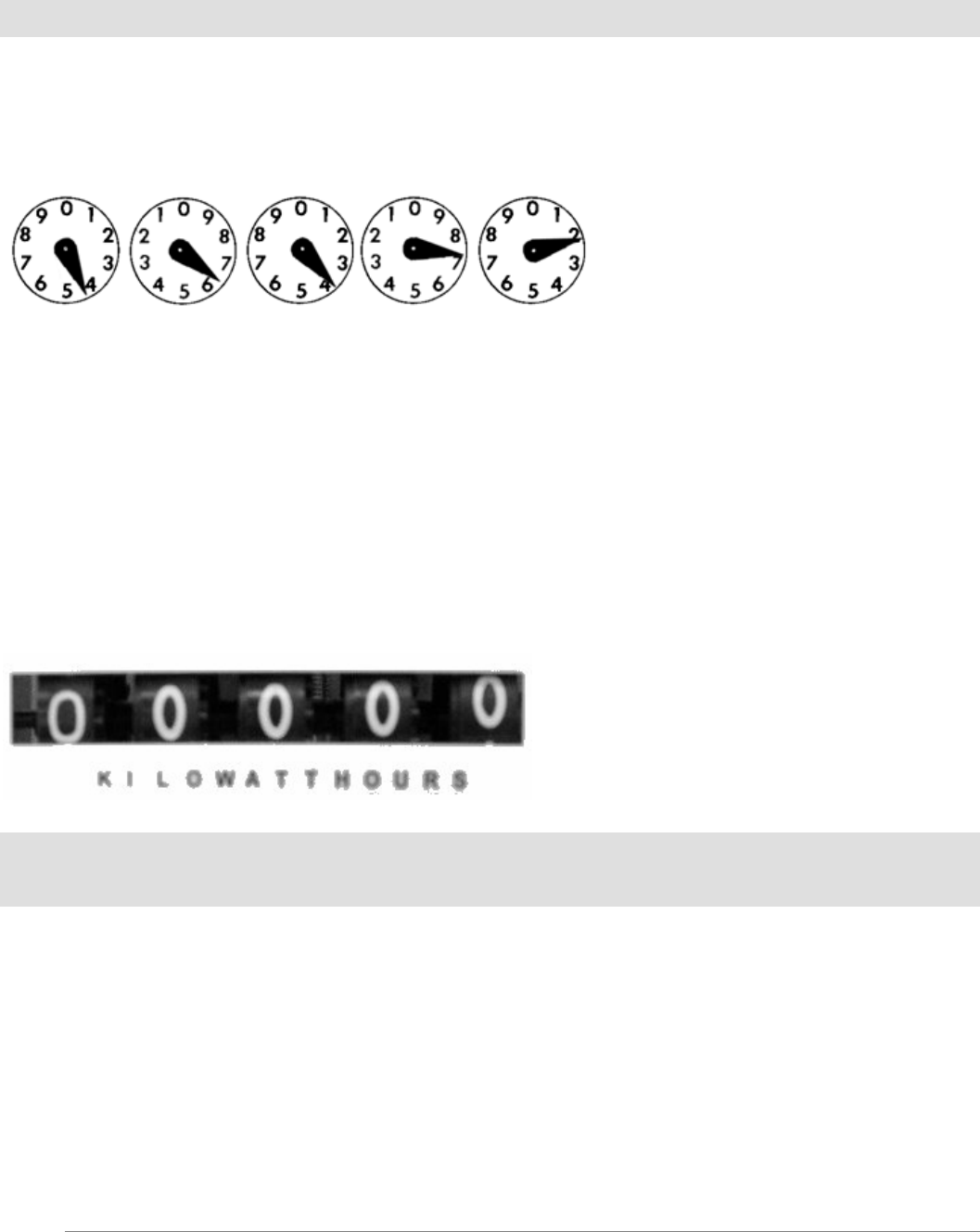
Following are some basic rules on how to read “clock style” electric meter indexes. Each of the four or five dials on the
meter represents one digit of the present reading. The dials move both clockwise and counter-clockwise. When the hand
of one of the dials is between numbers, always take the smaller number. For example:
Residential Electric meter example
4 6 3 7 2
This reading would be 46372. To tell if a hand is past a number or not, look at the dial to the right. If the dial to the
right has passed zero, then the hand is pointing to the correct number. If the dial to the right has not passed zero, then use
the next smaller number.
To practice, go outside a home or business and record the readings for several days in a row. By subtracting yesterday's
reading from today's reading, you can get a feel for how much energy (kilowatt hours for electric) is used each day.
When a power company representative reads a meter, they do not set it back to zero. Therefore, the dials keep turning
until the next time the meter is read. By subtracting two consecutive readings, the amount of consumption is determined
for the month. Utilities check to confirm that the readings each month fall within an expected range. If a reading is
significantly lower or higher than expected, the meter reader can be alerted and confirm the reading is correct. This helps
ensure bills are accurate each month.
This reading is 00000. Cyclometer (or odometer) style indexes
are easier to read and can be found on both electric meters.
©
Datamatic, Ltd. 2000-2008 page
11
Installation Procedures
Electric FIREFLY Installation Procedures
Pre-installation Setup
• Access the FIREFLY Template from the FIREFLY Menu.
• Select the type of service for the FIREFLY you are installing such as electric.
• Then you will select a prompt type for each parameter of either Normal or Default.
NORMAL - this means you are going to enter this value each time.
DEFAULT - this means you are setting it to a preset value that does not change.
When selecting Default, an actual value must then be entered for that parameter.
#1 Set your FIREFLY Template:
Parameter Prompt Type Value
(Recommended Value)
1. Reading Normal Normal
2. Register Number Normal Normal
3. Mode (makes the FF active) Default (Active)
4. System Number (area code for FFs) Default (100)
5. Prof. Interval (how often usage is saved) Default (15)
6. Transmit Interval (how often a FF sends
its signal) Default (2)
7. Constant (dependent upon the meter) Normal or Default (7.2, 12, 14.4)
8. Rollover (# Of Dials FIREFLY sends) Default (5)
9. Prof. Scale Default (1)
X. Save & Exit To Save your Template
#2 Set the Reading Mode
• Set the FIREFLY reading mode to Verify Read Mode.
#3 Check the Options Screen
Check the options screen from the FIREFLY Menu for the following:
• Capture Data – Enabled
• APD Register Number – Enabled
• Clear Prof. Data – Enabled
• Delta Warning – 2
• Show Constants – Disabled
• Comm Method – Wireless RF
• Tamper Override – Disabled
©
Datamatic, Ltd. 2000-2008 page
12
Installing the Electric FIREFLY
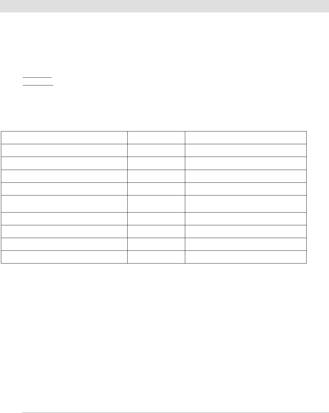
1. Remove the glass cover from the electric meter.
Remove the break-away brass tamper seal, if
equipped.
2. Remove the screws from the utility faceplate.
3. Remove the utility faceplate from the meter. Clean
the disc on old meters, if necessary.
4. Place marking template over meter disc, being sure to include one calibration
hole and any black painted stripe in the marking area.
Note: When painting the disc, make sure that any calibration holes that do not fall within the painted area will not be
positioned over the FIREFLY optics at the same time as the painted area.
©
Datamatic, Ltd. 2000-2008 page
13
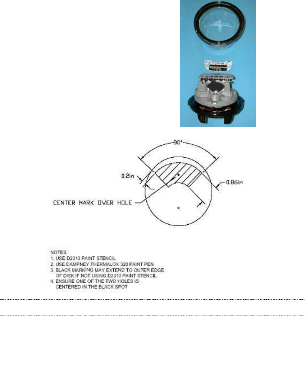
5. Using the Datamatic D2311 paint marker, paint in the entire area of the template. Leave no empty spots within the
template area.
Note: If the meter disc is already painted, still place template over disc to ensure the entire area is covered. If not, paint in
additional area within template not already covered with paint.
6. If required for this meter type, add metal extensions to the meter.
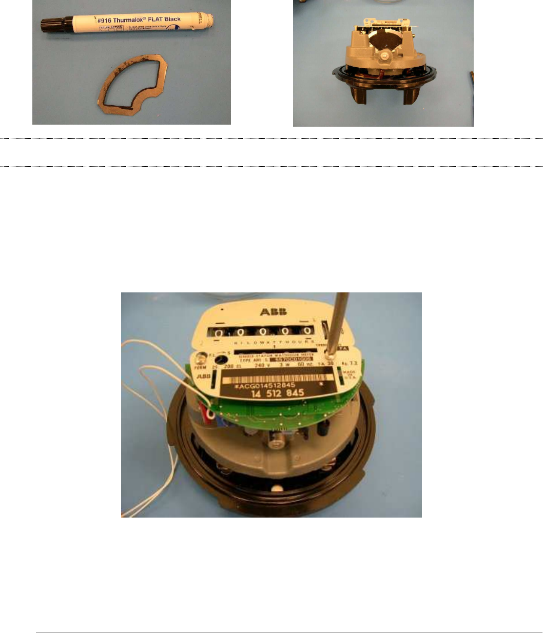
7. Position the FIREFLY on top of the nameplate posts.
8. Mount the unit flush on top of the nameplate posts with the spacer and nameplate above it.
9. Thread the mounting screw through the faceplate, the nylon spacer and FIREFLY into the faceplate post holes.
10. While applying pressure perpendicular to the disc plane, tighten down screws into faceplate post holes.
11. Make sure FIREFLY is parallel with the meter disc; adjust if needed. Ensure the meter disc moves freely.
©
Datamatic, Ltd. 2000-2008 page
14
12. Attach fuse clips on FIREFLY wire ends to the meter 240 VAC terminal posts on the top of the meter. This is the
city’s side of the meter. Avoid placing clips next to lightening arrestors.
Note: Do not attach the fuse clips to any painted area on the meter posts.
13. Replace the glass cover on the meter, making sure the FIREFLY wires do not get pinched between the meter and the
cover.
14. Optional: Test meter and calibrate on a test bench.
15. Install the meter into the 240V socket on a house or business, being careful to not jar the meter to prevent loosening
the FIREFLY batteries.
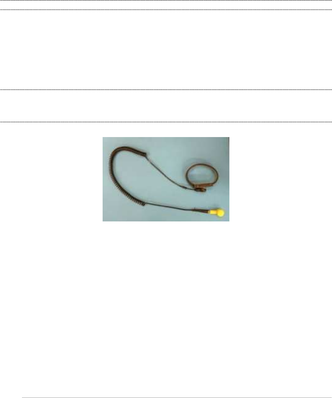
Note: All work on Electric FIREFLYs needs to be done taking static grounding precautions. Failure to use a grounded
static mat and wrist strap when handling or retrofitting the FIREFLY to an electric meter could result in static discharge
damage to the electronics. Units found to be damaged in this manner will not be covered by Datamatic warranty. See
picture of static mat below:

©
Datamatic, Ltd. 2000-2008 page
15
Electrostatic Discharge (ESD) Warning
Electrostatic Discharge (ESD) Warning
Electrostatic Discharge (ESD) is the enemy of electronic devices. You should always take precautions to eliminate any
electrostatic charge from your body and clothing before touching any semiconductor device or card by using an
electrostatic wrist strap and/or rubber mat.
Static electricity can harm system boards. Perform installation at an ESD workstation and follow proper ESD precautions
to reduce the risk of damage to devices. Datamatic strongly encourages you to follow proper ESD procedure, which can
include wrist straps and smocks, when servicing equipment.
You can also take the following steps to prevent damage from electrostatic discharge (ESD):
• When unpacking a static-sensitive device from its shipping carton, do not remove the device’s anti-static packaging
material until you are ready to install the device. Just before unwrapping the anti-static packaging, be sure you are at
an ESD workstation or grounded.
• When transporting a sensitive device, first place it in an antistatic container or packaging.
• Handle all sensitive devices at an ESD workstation. If possible, use anti-static floor pads and workbench pads.
• Handle devices and boards with care. Don’t touch the devices or contacts on a board. Hold a board by its edges or by
its metal mounting bracket.

©
Datamatic, Ltd. 2000-2008 page
16
Programming the Electric FIREFLY
Note: The FIREFLY requires 240VAC during programming to write settings to its memory.
1. Optional: Do the Meter Exchange Procedure. (F1 – D)
2. Power the meter with 240VAC (place the meter into the 240V socket).
3. Select Program FIREFLY from the FIREFLY Menu. (F5 – 2)
4. Select the addressing method by choosing #2. Serial Number.
5. Enter the 8-digit FIREFLY serial number located on the capacitor.
6. The ROADRUNNER begins initializing.
7. Select the meter brand you are installing the FIREFLY on. If the meter brand is not listed (but qualified by Datamatic)
use “Other” and type in brand name.
8. Enter the register number from meter (if not automatically populated with correct meter number from account).
9. Enter the visual reading for all 5 visible dials.
10. At the View Current Settings screen, check normal values entered on template. Press the ‘FNCTN’ and ‘End’ keys to
accept the values.
11. Select Save and Exit.
12. When the ROADRUNNER has returned to the route, take a Walk-Away Reading in Verify Read mode by
Interrogating the FIREFLY (press I).
13. Initial installation and programming of FIREFLY is complete.
Notes:
If you do not receive an RF message or signal for an extended period of time, one of two issues may have occurred:
• FIREFLY was mis-programmed (usually the Meter# being incorrect).
• The FIREFLY is not putting out an RF signal.
To exit the interrogation screen, press the ‘FNCTN’ and ‘End’ keys. You receive a screen to either select:
1. Skip Meter – then enter a Skip code.
2. Exit Install Read – takes you back to the route screen.
Select #2, Exit Install Read. Go back to Step #2 to reprogram the FIREFLY once more.
Troubleshooting Electric and FIREFLYs
Reports are generated from Installation and RV data that is sent to Datamatic. These reports are processed and then e-
mailed back to the customers for review. These reports are used to identify which FIREFLYs need Troubleshooting.
Examples of FIREFLYs in need of Troubleshooting include No RF signal and Delta values outside of specified range.

©
Datamatic, Ltd. 2000-2008 page
17
Troubleshooting Field Procedure
The following steps should be taken to troubleshoot FIREFLY issues while in the field:
• Perform a Walk-Up RV (see Read and Verify Procedure section of this manual).
• If walk-up RV is accurate, proceed to the next meter on the Troubleshooting report.
• If the FIREFLY is inaccurate or has any Trouble Codes then proceed with Troubleshooting.
Troubleshooting Details
Check the following before troubleshooting the FIREFLY:
• The dials are not stuck or malfunctioning.
• Make sure the FIREFLY has no visible damage.
Receiving no RF signal from a FIREFLY
When Interrogating a FIREFLY from a ROADRUNNER and no radio read can be made, check the following:
• Check Current Settings to verify the register # on the meter, ROADRUNNER, and FIREFLY match.
• Verify that in Current Settings of the FIREFLY, the Mode is showing to be ‘Active’.
Inaccurate Under-counting FIREFLY
Electric FIREFLY:
• Check connection of FIREFLY to power posts. Reconnect using the proper technique if needed.
• Confirm there are no reflective unpainted areas within the painted area of the disc.
• Check meter disc speed; excessive disc spend can cause under-counting. Continually undercounting deltas usually
mean the account has an under-sized meter, making both the meter and FIREFLY miss counts.
©
Datamatic, Ltd. 2000-2008 page
18
Sample Datamatic FIREFLY Reports
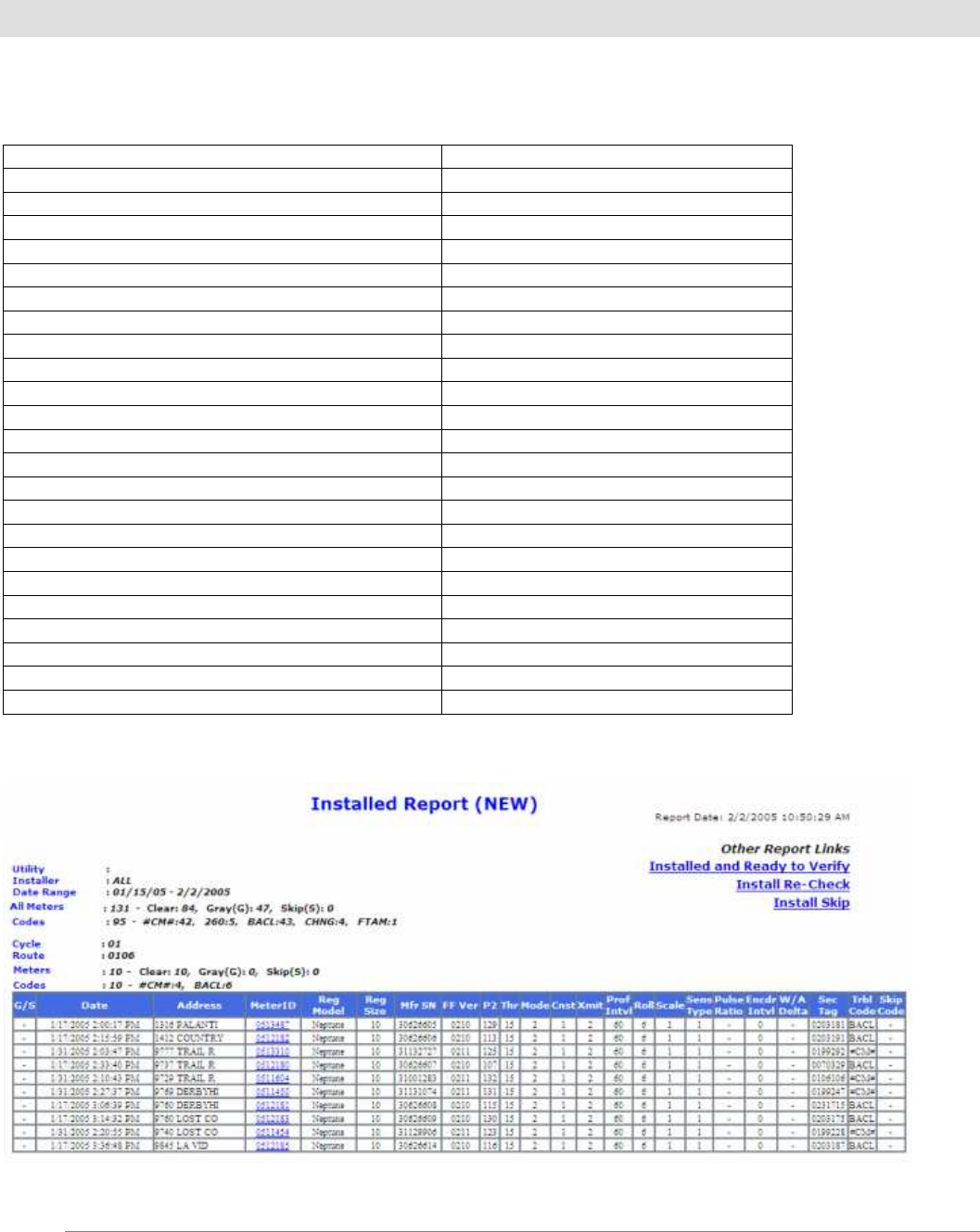
Installed Report
Here are the Variables and Fields that are included on an Installed FIREFLY report:
Variables: Fields included:
Utility G/S – Gray/Skip indicator
Installer Date
Include Utility (Yes/No) Address
Include Admin Installer (Yes/No) Meter ID
Cycle Register Model
Start Date Register Size
End Date Manf Serial #
Route FF Version
P2
Thresh
Mode
Constant
Transmit Interval
Profile Interval
Rollover
Scale
Sensor Type
Pulse Ratio
Encoder Interval
Walkway Delta
Security Tag
Trouble Code
Skip Code
Example of an Installed FIREFLY report:
©
Datamatic, Ltd. 2000-2008 page
19
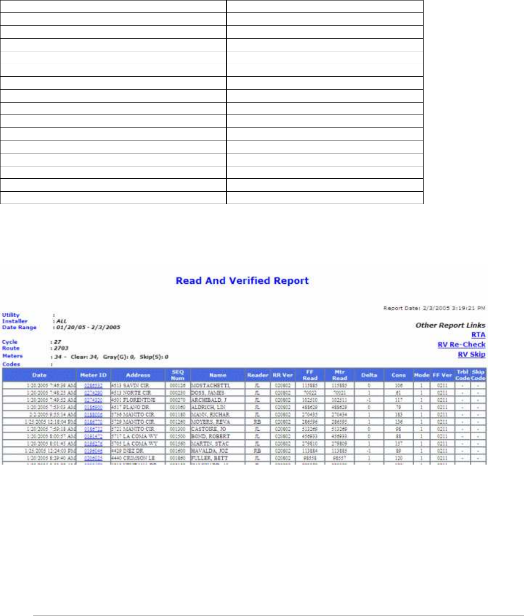
Read and Verified Report
Here are the Variables and Fields that are included on Read and Verified FIREFLY report:
Variables: Fields included:
Utility Date/Time
Installer Meter ID
Include Utility (Yes/No) Address
Include Admin Installer (Yes/No) Sequence #
Cycle Name
Start Date Reader
End Date RR Version
Route FF Read
Meter Read
Delta
Consumption (since last set date)
Mode
FF Ver
Trouble Code
Skip Code
Example of a Read and Verified FIREFLY report:

©
Datamatic, Ltd. 2000-2008 page
20
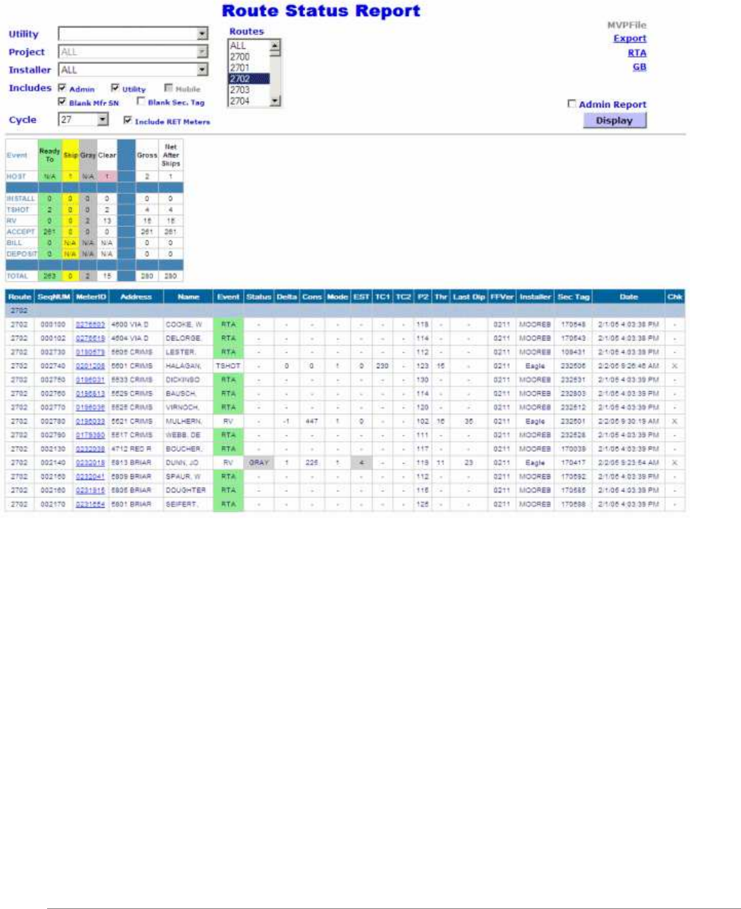
Route Status Report
Here are the Variables and Fields that are included on a Route Status FIREFLY report:
Variables: Fields included:
Utility Route
Include Admin Installer (Yes/No) Sequence Number
Cycle Meter ID
Route Address
Include Retired Meters (Yes/No) Name
Admin Report (For Administrators Only) Event
Status
Delta
Consumption
Mode
Extended Status
Trouble Code 1
Trouble Code 2
P2
Thresh
FF Version
Installer (* Installer will be name of Admin
if Include Admin Installer is checked and
Admin was the last record)
Security Tag
Date
Chk (* for engineering purposes only)
©
Datamatic, Ltd. 2000-2008 page
21
Example of a Route Status FIREFLY report: