Datto OM5PAC Wireless Access Point User Manual rev
Open Mesh, Inc. Wireless Access Point rev
UserManual.wiki
>
Datto
>
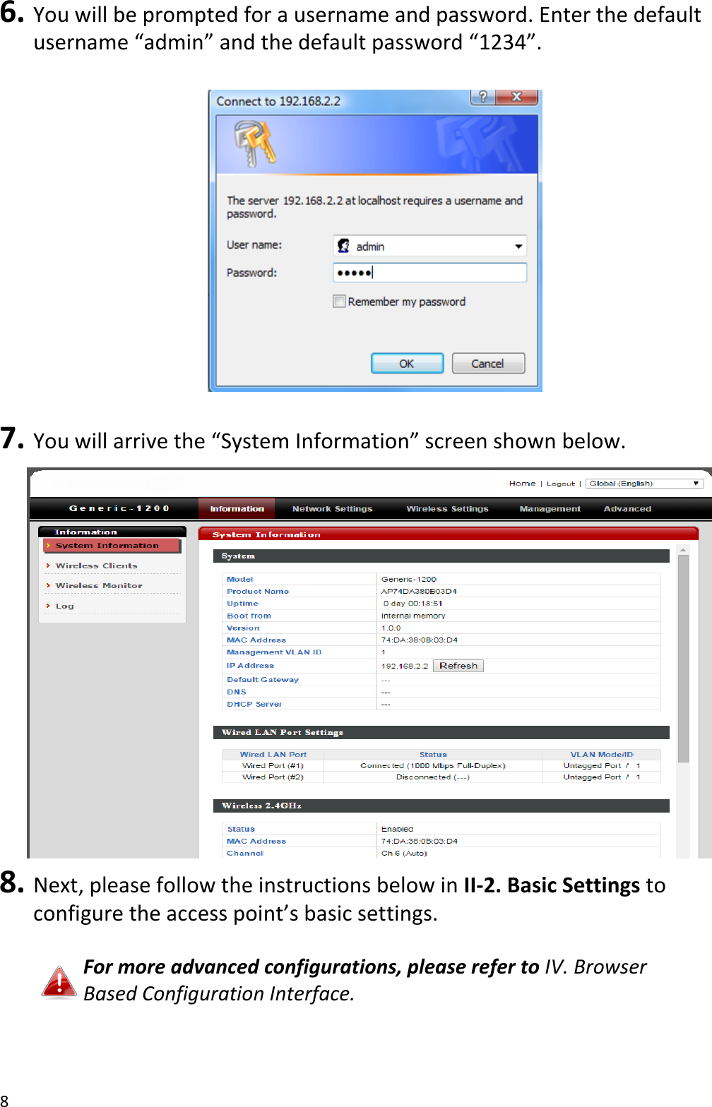
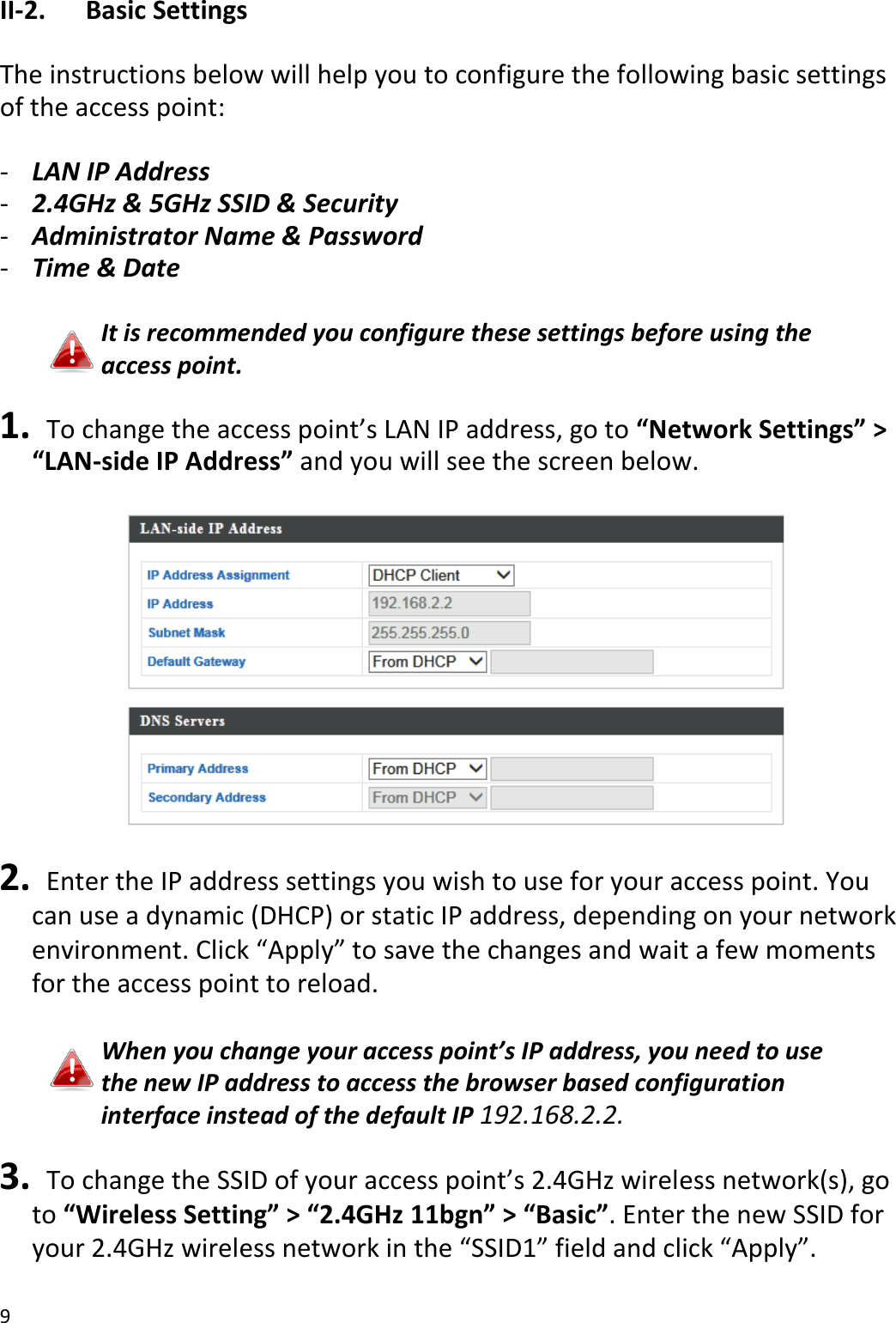
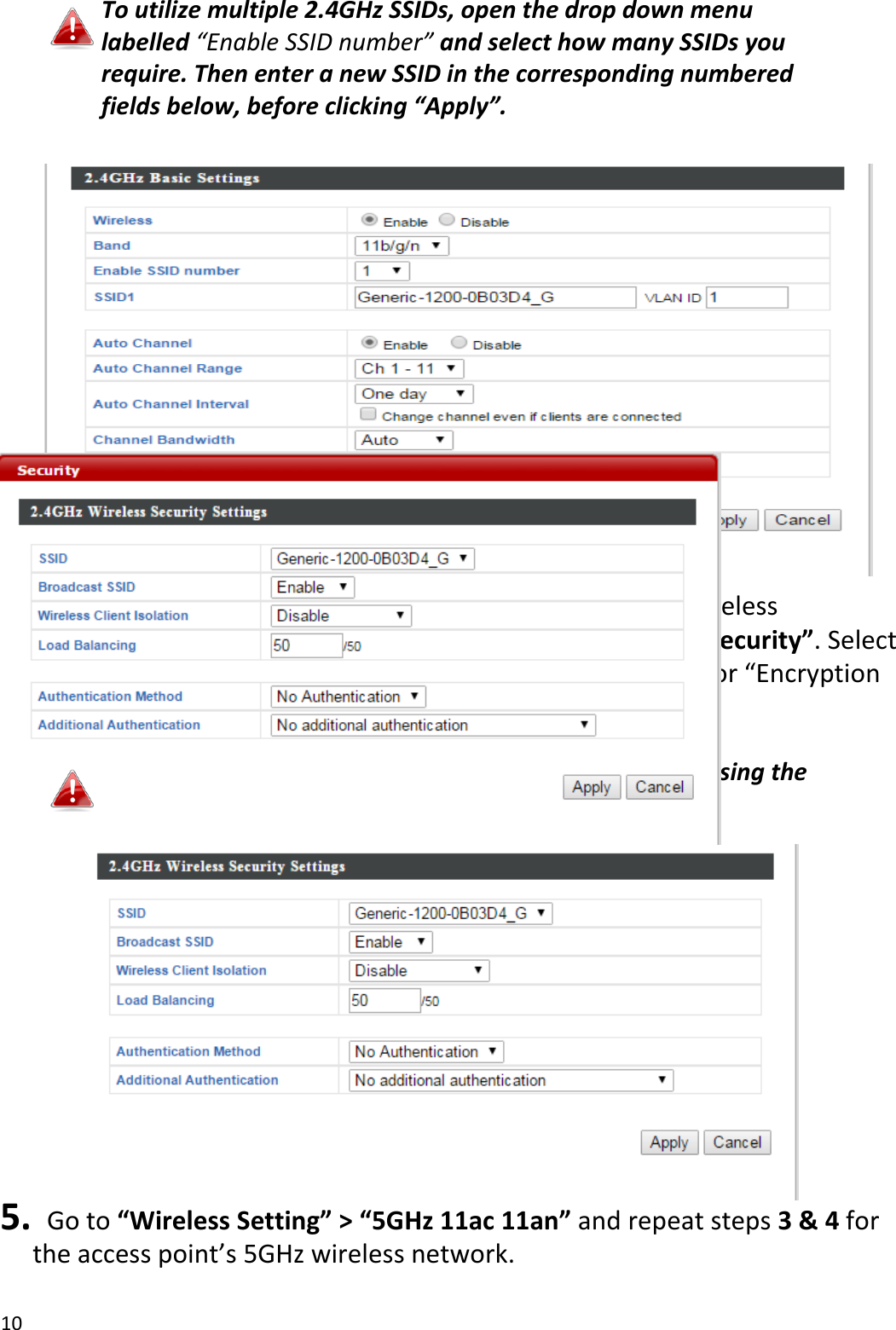
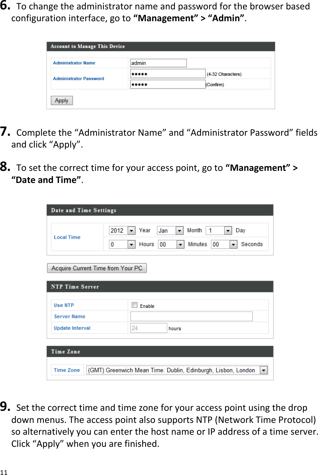
OM5PAC User Manual
User Manual_rev.pdf
Navigation menu
Upload a User Manual
Namespaces
Wiki Guide
HTML
PDF
Info
Views
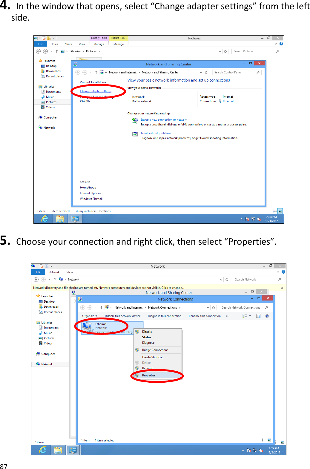
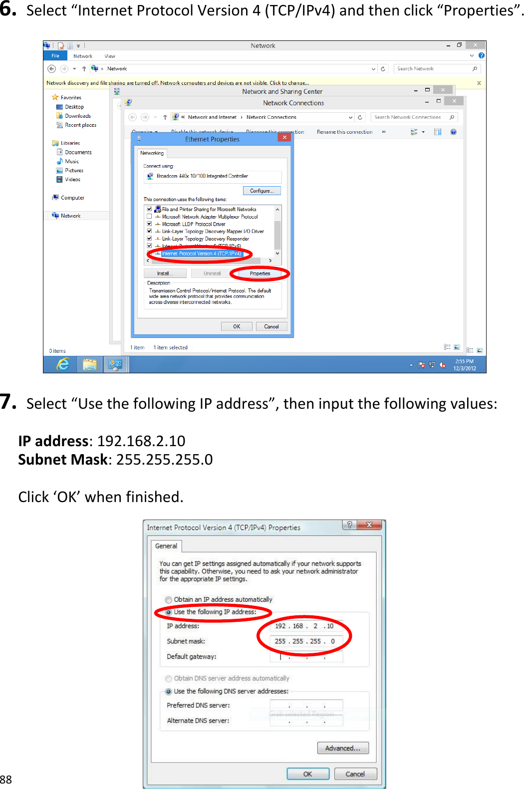
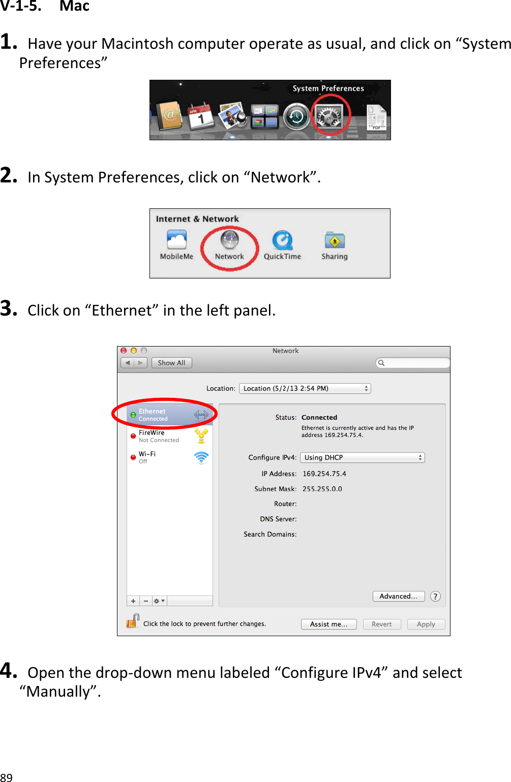
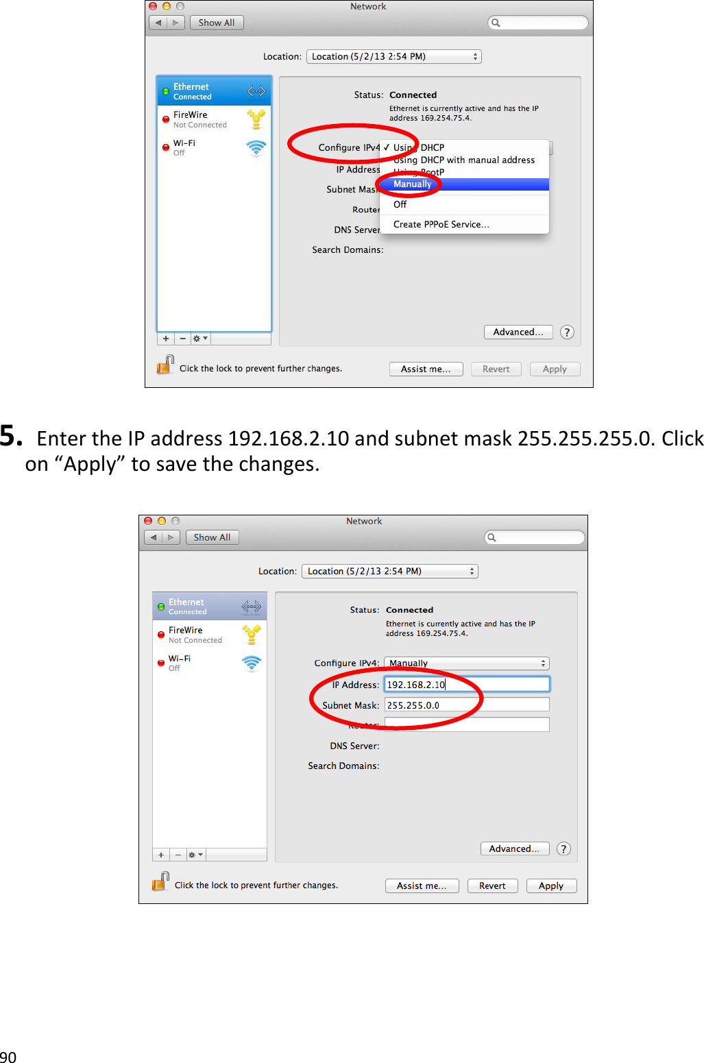
User Manual
Discussion / Help
Navigation

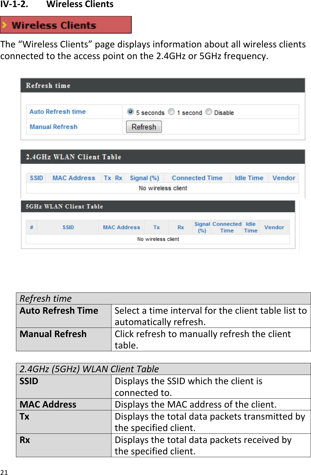
![25 The following information/events are recorded by the log: USB Mount & unmount Wireless Client Connected & disconnected Key exchange success & fail Authentication Authentication fail or successful. Association Success or fail Change Settings System Boot Displays current model name NTP Client Wired Link LAN Port link status and speed status Proxy ARP Proxy ARP module start & stop Bridge Bridge start & stop. SNMP SNMP server start & stop. HTTP HTTP start & stop. HTTPS HTTPS start & stop. SSH SSH-client server start & stop. Telnet Telnet-client server start or stop. WLAN (2.4G) WLAN (2.4G] channel status and country/region status WLAN (5G) WLAN (5G) channel status and country/region status ADT](https://usermanual.wiki/Datto/OM5PAC/User-Guide-2629576-Page-28.png)