Datto OMA60 WiFi Access Point User Manual A60 Quick Start Guide v1 3 1116

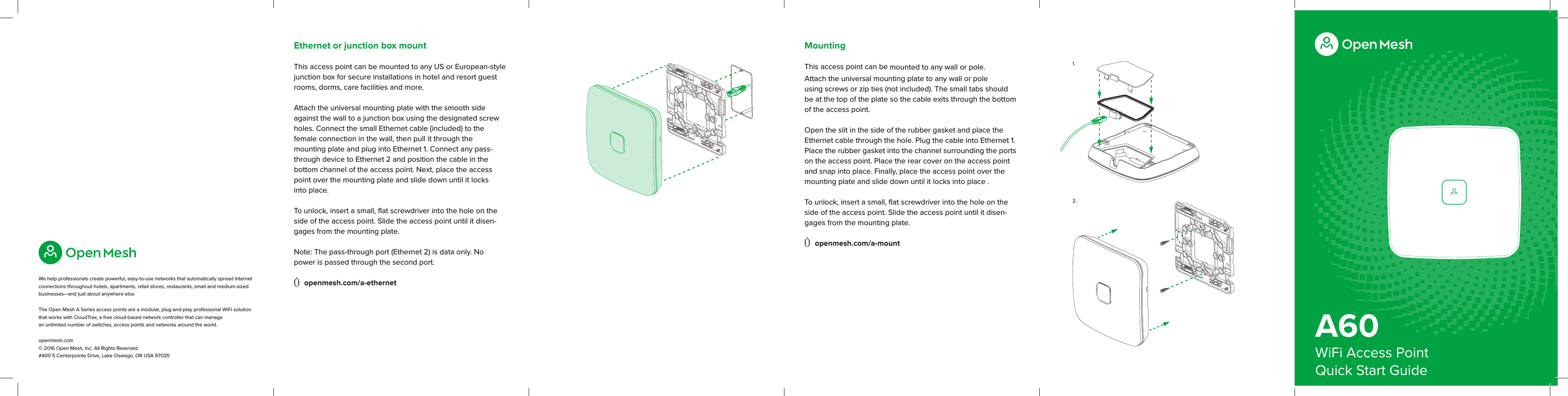
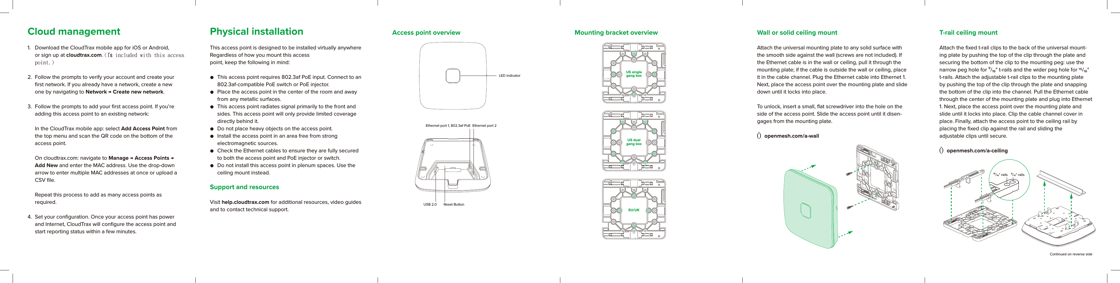
Open Mesh, Inc. WiFi Access Point A60 Quick Start Guide v1 3 1116

Users Manual

A60WiFi Access PointQuick Start GuideWe help professionals create powerful, easy-to-use networks that automatically spread Internet connections throughout hotels, apartments, retail stores, restaurants, small and medium-sized businesses—and just about anywhere else. The Open Mesh A Series access points are a modular, plug-and-play professional WiFi solution that works with CloudTrax, a free cloud-based network controller that can manage  an unlimited number of switches, access points and networks around the world.openmesh.com © 2016 Open Mesh, Inc. All Rights Reserved. #400 5 Centerpointe Drive, Lake Oswego, OR USA 970351.2.MountingThis access point can be mounted to any wall or pole. Attach the universal mounting plate to any wall or pole using screws or zip ties (not included). The small tabs should be at the top of the plate so the cable exits through the bottom of the access point. Open the slit in the side of the rubber gasket and place the Ethernet cable through the hole. Plug the cable into Ethernet 1. Place the rubber gasket into the channel surrounding the ports on the access point. Place the rear cover on the access point and snap into place. Finally, place the access point over the mounting plate and slide down until it locks into place . To unlock, insert a small, flat screwdriver into the hole on the side of the access point. Slide the access point until it disen-gages from the mounting plate. Ò openmesh.com/a-mountEthernet or junction box mountThis access point can be mounted to any US or European-style junction box for secure installations in hotel and resort guest rooms, dorms, care facilities and more. Attach the universal mounting plate with the smooth side against the wall to a junction box using the designated screw holes. Connect the small Ethernet cable (included) to the  female connection in the wall, then pull it through the  mounting plate and plug into Ethernet 1. Connect any pass-through device to Ethernet 2 and position the cable in the  bottom channel of the access point. Next, place the access point over the mounting plate and slide down until it locks  into place.To unlock, insert a small, flat screwdriver into the hole on the side of the access point. Slide the access point until it disen-gages from the mounting plate. Note: The pass-through port (Ethernet 2) is data only. No  power is passed through the second port.Ò openmesh.com/a-ethernet
T-rail ceiling mountAttach the fixed t-rail clips to the back of the universal mount-ing plate by pushing the top of the clip through the plate and securing the bottom of the clip to the mounting peg: use the narrow peg hole for ⁹/₁₆" t-rails and the wider peg hole for  /₁₆" t-rails. Attach the adjustable t-rail clips to the mounting plate by pushing the top of the clip through the plate and snapping the bottom of the clip into the channel. Pull the Ethernet cable through the center of the mounting plate and plug into Ethernet 1. Next, place the access point over the mounting plate and slide until it locks into place. Clip the cable channel cover in place. Finally, attach the access point to the ceiling rail by  placing the fixed clip against the rail and sliding the  adjustable clips until secure.Ò openmesh.com/a-ceilingLED indicatorEthernet port 1, 802.3af PoEReset ButtonUSB 2.0Ethernet port 2US singlegang boxUS dualgang boxEU/UKContinued on reverse sideCloud management1.  Download the CloudTrax mobile app for iOS or Android, or sign up at cloudtrax.com. (It's included with this access point.)2.  Follow the prompts to verify your account and create your first network. If you already have a network, create a new one by navigating to Network → Create new network. 3.  Follow the prompts to add your first access point. If you’re adding this access point to an existing network:  In the CloudTrax mobile app: select Add Access Point from the top menu and scan the QR code on the bottom of the access point.   On cloudtrax.com: navigate to Manage → Access Points → Add New and enter the MAC address. Use the drop-down arrow to enter multiple MAC addresses at once or upload a CSV file.   Repeat this process to add as many access points as  required. 4.  Set your configuration. Once your access point has power and Internet, CloudTrax will configure the access point and start reporting status within a few minutes.Access point overview Mounting bracket overviewPhysical installationThis access point is designed to be installed virtually anywhere Regardless of how you mount this access point, keep the following in mind:   This access point requires 802.3af PoE input. Connect to an 802.3af-compatible PoE switch or PoE injector.   Place the access point in the center of the room and away from any metallic surfaces.  This access point radiates signal primarily to the front and sides. This access point will only provide limited coverage directly behind it.   Do not place heavy objects on the access point.  Install the access point in an area free from strong  electromagnetic sources.  Check the Ethernet cables to ensure they are fully secured to both the access point and PoE injector or switch.  Do not install this access point in plenum spaces. Use the ceiling mount instead. Support and resourcesVisit help.cloudtrax.com for additional resources, video guides and to contact technical support.Wall or solid ceiling mountAttach the universal mounting plate to any solid surface with the smooth side against the wall (screws are not included). If the Ethernet cable is in the wall or ceiling, pull it through the mounting plate; if the cable is outside the wall or ceiling, place it in the cable channel. Plug the Ethernet cable into Ethernet 1. Next, place the access point over the mounting plate and slide down until it locks into place. To unlock, insert a small, flat screwdriver into the hole on the side of the access point. Slide the access point until it disen-gages from the mounting plate. Ò openmesh.com/a-wall¹⁵/ " rails ⁹/ " rails
2016/11/166709A2463320品牌產品規劃PM請勿列印此頁Don’t  print this page.
Federal Communication Commission Interference StatementThis equipment has been tested and found to comply with the limits for a Class B digital device,pursuant to Part 15 of the FCC Rules. These limits are designed to provide reasonable protectionagainst harmful interference in a residential installation. This equipment generates, uses, and canradiate radio frequency energy and, if not installed and used in accordance with the instructions, maycause harmful interference to radio communications. However, there is no guarantee that interferencewill not occur in a particular installation. If this equipment does cause harmful interference to radio ortelevision reception, which can be determined by turning the equipment off and on, the user isencouraged to try to correct the interference by one or more of the following measures:• Reorient or relocate the receiving antenna.• Increase the separation between the equipment and receiver.• Connect the equipment into an outlet on a circuit different from that to which the receiver is connected.• Consult the dealer or an experienced radio/TV technician for help.FCC Caution:This device complies with Part 15 of the FCC Rules. Operation is subject to the following two conditions:(1) This device may not cause harmful interference, and (2) this device must accept any interferencereceived, including interference that may cause undesired operation.Non-modification Statement:Changes or modifications not expressly approved by the party responsible for compliance could void the user'sauthority to operate the equipment.FCC Radiation Exposure Statement:This equipment complies with FCC radiation exposure limits set forth for an uncontrolled environment.This equipment should be installed and operated with minimum distance 20cm between the radiator &your body.
This device complies with Industry Canada licence-exempt RSS standard(s).Operation is subject to the following two conditions:(1) This device may not cause interference, and(2) This device must accept any interference, including interference that may causeundesired operation of the device.Le présent appareil est conforme aux CNR d'Industrie Canada applicables aux appareils radioexempts de licence.L'exploitation est autorisée aux deux conditions suivantes:(1) l'appareil ne doit pas produire de brouillage, et(2) l'utilisateur de l'appareil doit accepter tout brouillage radioélectrique subi, même si lebrouillage est susceptible d'en compromettre le fonctionnement.This device complies with RSS 210 of Industry Canada. This Class B device meets allthe requirements of the Canadian interference-causing equipment regulations.Cet appareil numérique de la Classe B respecte toutes les exigences du Règlement sur lematériel brouilleur du Canada.IC Radiation Exposure StatementThis equipment complies with IC RSS-102 radiation exposure limit set forth for an uncontrolledenvironment. This equipment should be installed and operated with minimum distance 20cm betweenthe radiator and your body.Déclaration d’exposition àla radiation : Cet équipement respecte les limites d’exposition auxrayonnements IC définies pour un environnement non contrôlé. Cet équipement doit être installé etmis en marche à une distance minimale de 20 cm qui sépare l’élément rayonnant de votre corps.L’émetteur ne doit ni être utilisé avec une autre antenne ou un autre émetteur ni se trouver à leurproximité.

Navigation menu