David Clark U9921 UNIVERSAL FIXED PART GATEWAY CONTAINING DECT TRANSCEIVER (UPCS) User Manual 40994G 01 U9921 GUV
David Clark Company Inc. UNIVERSAL FIXED PART GATEWAY CONTAINING DECT TRANSCEIVER (UPCS) 40994G 01 U9921 GUV
Users Manual
19541P‐42(02‐11)
©2011DAVIDCLARKCOMPANYINCORPORATED
U9921-GUV
(P/N: 40994G-01)
Universal Gateway
USER MANUAL

1of8
19541P‐42(02‐11)
C
Ca
au
ut
ti
io
on
ns
s
a
an
nd
d
W
Wa
ar
rn
ni
in
ng
gs
s
READANDSAVETHESEINSTRUCTIONS.Followtheinstructionsinthisinstallation
manual.Theseinstructionsmustbefollowedtoavoiddamagetothisproductand
associatedequipment.Productoperationandreliabilitydependsonproperusage.
DONOTINSTALLANYDAVIDCLARKCOMPANYPRODUCTTHAT
APPEARSDAMAGED.UponunpackingyourDavidClarkproduct,
inspectthecontentsforshippingdamage.Ifdamageisapparent,
immediatelyfileaclaimwiththecarrierandnotifyyourDavidClark
productsupplier.
ELECTRICALHAZARD‐Disconnectelectricalpowerwhenmakingany
internaladjustmentsorrepairs.Allrepairsshouldbeperformedbya
representativeorauthorizedagentoftheDavidClarkCompany.
STATICHAZARD‐Staticelectricitycandamagecomponents.
Therefore,besuretogroundyourselfbeforeopeningorinstalling
components.
LI‐POLYMER‐ThisproductisusedwithLi‐Polymerbatteries.Donot
incinerate,disassemble,shortcircuit,orexposethebatterytohigh
temperatures.Batterymustbedisposedofproperlyinaccordance
withlocalregulations.
2of8
19541P‐42(02‐11)
O
Ov
ve
er
rv
vi
ie
ew
w
TheU9921‐GUV(40994G‐01)UniversalGatewayisafixed‐mountedwirelesscommunication
devicethat,whenusedinconjunctionwithoneormoreU9910‐BSW(40992G‐01)orU9912‐
BSW(40992G‐02)WirelessBeltStations,becomespartofawirelessintercomsystem.The
U9921‐GUVprovidescommunicationforuptofourusersaswellasaninterfacetoanexisting
wiredintercomsystem.Uptofourbeltstationscanbeconnectedtoonegateway.
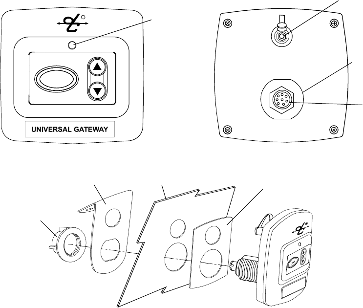
Status LED
Gasket
Bracket
Nut
Panel
Antenna
Connection
Threaded
Post
Interface
Connector
LINK VOL
R
Figure1:OverviewofGateway

3of8
19541P‐42(02‐11)
I
In
ns
st
ta
al
ll
la
at
ti
io
on
n
IntercomInterface
TheU9921‐GUVisdesignedtoaddwirelesscapabilitytoanexistingwiredintercom.Connection
totheintercomisaccomplishedbyconnectinganinterfacecabletotheinterfaceconnectorof
theU9921‐GUV(seeFigure1).ThefollowinglistcontainsDavidClarkintercomsystemsthat
havebeentestedtoworkwiththeU9921‐GUVandtherequiredcableassembly.
Table1:IntercomInterfaceCableAssemblies
DavidClarkIntercomCableAssemblyRequired
U3800VehicularIntercomSystem C99‐22MS(40935G‐08)
U9800MarineIntercomSystemC99‐20CX(40935G‐07)
U9500MarineIntercomSystemC99‐20LL(40935G‐06)
U3400PortableIntercomSystem
U3100ModularIntercomSystemC99‐20MS(40935G‐05)
TheU9921‐GUVwilldetectthecableassemblieslistedaboveandautomaticallymakethe
necessaryaudioleveladjustmentsforthecorrespondingintercom.
Mounting
TheU9921‐GUVmaybeflushmountedorsurfacemountedusingtheincludedgasket,nut,and
bracket.SeeFigure1formountingsuggestions.
Note:Bracketnotusedforflushmountapplications.Bracketmountingconfigurationmaybe
reversedforvaryingrequirements(e.g.,vehicledashvs.ceiling‐mount.)
Antenna
TheU9921‐GUVhasaninternalantenna.Anexternalantennamaynotbenecessarybutthe
antennaconnectorisprovidedforeithertheincludedwhipantennaoranoptionalremote
antennakit(P/N:40688G‐93).
Chooseanopen,clearlocationfortheremoteantennaandroutethecoaxialcableawayfrom
anybusyareas,preferablybehindpanelsorinconduits.
Thisdevicehasbeendesignedtooperatewiththeantennaslistedbelow,andhavinga
maximumgainof3dB.Antennasnotincludedinthislistorhavingagaingreaterthan3dBare
strictlyprohibitedforusewiththisdevice.Therequiredantennaimpedanceis50ohms.
Acceptableantennasforusewiththisproduct:
• WhipAntenna(P/N:40688G‐92)
• RemoteAntennaKit(P/N:40688G‐93)

4of8
19541P‐42(02‐11)
L
Li
in
nk
ki
in
ng
g
Beforeabeltstationandagatewaycanbeconnected,theymustfirstbelinked.Asasecurity
measure,theclose‐linkfeaturerequiresdevicestobeinproximityofbetween1to3ft(0.3to
0.9m)inordertosuccessfullylink.Thisensuresthattheunitsarenotinadvertentlylinkedwith
otherunitsonthepremises.
Linkingprocedure:
1. Ensureunitsarewithin1to3ft(0.3to0.9m)ofeachother.
2. Simultaneously(within1‐2sec)pressandreleasetheLINKbuttonontheU9921‐GUVand
thepowerbuttononthebeltstationtolinkwith.
3. AmberLED’swillflashonbothdevices.AmomentaryredLEDindicatesasuccessful
close‐link.
4. UponsuccessfullinktheU9921‐GUVwillattempttoestablishaconnectionwiththebelt
station.
5. UponsuccessfullyestablishingconnectiontheLEDonthecontrollerwillflashagreen
patterncorrespondingtothenumberofbeltstationsconnected.
Tip:
Oncelinked,thedeviceswillnotneedtobelinkedagainunlesstheyarepurged(see
Purging).
Eachbeltstationisabletobelinkedtoonlyonegatewayatatime.Agatewaycanhaveuptosix
beltstationslinkedandbeconnectedtofourofthosesixatonetime.
S
St
ta
at
tu
us
s
I
In
nd
di
ic
ca
at
ti
io
on
ns
s
Thefrontpanelhasamulti‐colorLEDinthecenterwhichservesasastatusindicationforthe
gateway.Table1belowliststhesestates.
Table2:LEDStatusIndications
LEDColorBlinkRateStatus
RedSolidInitializing/powerup
RedOnceConnectionDropped
RedOnceConnectionEstablished
RedAnyLowbattery(approx.1hrremaining)
OrangeSlowIdle/Disconnected
OrangeFastLink/ConnectioninProgress
OrangeSolidPTTasserted
GreenSlowConnected(patternindicates
numberofbeltstationsconnected)

5of8
19541P‐42(02‐11)
O
Op
pe
er
ra
at
ti
io
on
n
Communication
AllconnectedbeltstationswillbeabletocommunicatewitheachotherthroughtheU9921‐GUV
whileinrange(andpertheVOXsettingsonaVOXbeltstation.)Additionally,allbeltstation
userswillhavecommunicationovertheintercom.Iftheintercomissoequipped,pressingthe
PTTbuttononaVOXbeltstationwillallowtheusertotransmitoverthesystem’stwo‐wayradio.
PressingthePTToverridestheVOXsettingonaVOXbeltstation.MultipleVOXbeltstationusers
mayPTTandthusspeakoverthetwo‐wayradiosimultaneously.Formoreinformationconsult
theusermanualforthebeltstation.
Tip:
WirelessuserswhoarenotpressingPTTwhileanotherwirelessuserispressingPTT
willnotbeheardonthewiredintercomwhilethePTTremainspressed.
IntercomLevelAdjustment
Audiolevelscanvarybetweenintercoms,mainlyduetothesystemlevelsettingonthewired
intercom.Tocompensateforthis,theU9921‐GUVhastheabilitytoadjustitsreceivelevelfrom
theintercomusingtheVolkeys(seeFigure1).Pressingthesekeyswillincreaseordecreasethe
audiolevelcomingfromthewiredintercomintothegateway.Performthisadjustmenttoobtain
optimumperformance.
ReceiveLevelAdjustmentProcedure
1. ConnectatleastonebeltstationtotheU9921‐GUVgatewayandensuresidetoneis
present(seebeltstationUserManual).
2. BeginspeakingandslowlyandrepeatedlypresstheVolumeUpkeyontheU9921‐
GUVgatewayuntilyouhearanechoofyourownvoice.
3. ContinuespeakingandpresstheVolumeDownkeyuntiltheechostops.
4. Youmaywishtoverifycommunicationwithsomeonehard‐wiredtotheintercom.
Range
Therangeofabeltstationandagatewaycanbeupto300ft(100m).Ifyouareinan
environmentwithmetalorconcretewalls,thisrangecouldbereduced.Whenthebeltstation
travelsoutofrangeofthegateway,avoicealertwillindicatethattheconnectionhasbeenlost.
Toreconnect,simplymovebackintorangeandconnectionwiththegatewaywillautomatically
bereestablished,alsonotedbyavoicealert.

6of8
19541P‐42(02‐11)
P
Pu
ur
rg
gi
in
ng
g
Insomecircumstancesitmaybenecessaryto“purge”theU9921‐GUVofsomeofitslinkedbelt
stations.Typicallypurgingisnotnecessaryunlesstherearemultiplegatewaysinthesame
vicinityandyouwishtoremoveabeltstationfromthisgatewayandlinktoadifferentgateway.
Agatewaycanlinkuptosixbeltstationswhereabeltstationcanbelinkedtoonlyonegateway
atatime.
SmartPurge
AsmartpurgeisthepurgemethodemployedfortheU9921‐GUV,inwhichonlyunwantedlinks
areremovedfromthegateway.Whenthisprocedureiscomplete,onlybeltstationsthatare
connectedtothegatewayremainlinked.Allotherbeltstationlinkswillhavebeenremoved(see
thebeltstationUserManualfortheindividualbeltstationpurgingprocedurewhenremaining
linkpurgingmaybenecessary.)
SmartPurgeprocedure
1. Ensurethegatewayispoweredonandfunctioning.
2. Disconnectallbeltstationstobepurged(poweroffthebeltstations).
3. VerifythenumberofgreenLEDflashesonthegatewaymatchesthenumberof
beltstationstobekeptlinked.
4. PressandholdLINKbuttononthegatewayfor30secondsuntilLEDquickly
flashesred.
5. ReleaseLINKbutton.
T
Tr
ro
ou
ub
bl
le
es
sh
ho
oo
ot
ti
in
ng
g
Table3:Troubleshooting
ProblemSolution
GatewaywillnotturnonEnsurecorrectinterfacecableisbeingused
(Table2)
CannotlinkabeltstationReviewRegistrationprocedure
Ensureunitsarewithin1to3ft(0.3to0.9m)of
eachother
TryaSmartPurge
Cannotspeakovertwo‐way
radio
PTTnotpressed
Two‐wayradionotinstalledtosystem

7of8
19541P‐42(02‐11)
R
Re
ep
pl
la
ac
ce
em
me
en
nt
t
P
Pa
ar
rt
ts
s
• Interfacecableassemblies:
DavidClarkIntercomCableAssemblyRequired
U3800VehicularIntercomSystem C99‐22MS(40935G‐08)
U9800MarineIntercomSystemC99‐20CX(40935G‐07)
U9500MarineIntercomSystemC99‐20LL(40935G‐06)
U3400PortableIntercomSystem
U3100ModularIntercomSystemC99‐20MS(40935G‐05)
• WhipAntenna(P/N:40688G‐92)
• RemoteAntennaKit(P/N:40688G‐93)
C
Ca
ar
re
e
a
an
nd
d
M
Ma
ai
in
nt
te
en
na
an
nc
ce
e
TheU9921‐GUVisnotuserserviceable.Donotattempttoopentheenclosure.Ifthisproduct
requiresservice,pleasecontacttheDavidClarkCustomerServicedepartment:
• Phone: 800.298.6235
• E‐Mail:serviceWWW@DavidClark.com
• ByMail:CustomerService
DavidClarkCompany
360FranklinStreet
Worcester,MA01604
Ifnecessary,theU9921‐GUVmaybewipeddownwithamildsoapandwatermixture.Although
itisasealeddevicedesignedtowithstandsubmersioninwaterto1meter,donotunnecessarily
submersethisproductinwater.
Avoidstorageofthisproductindirectsunlightorhightemperatureenvironments.
S
Sp
pe
ec
ci
if
fi
ic
ca
at
ti
io
on
ns
s
FrequencyRange1920MHz‐1930MHz(U.S.andCanada)
1880MHz‐1900MHz(EU)
AverageRFPowerOutput4mW(100mWpeak)(U.S.andCanada)
10mW(250mWpeak)(EU)
Range300ft(100m)line‐of‐sight(nominal)
OperatingTemperature‐14°Fto113°F(‐10°Cto+45°C)
StorageTemperature‐4°Fto140°F(‐20°Cto+60°C)
PowerRequirements8to25VDC
8of8
19541P‐42(02‐11)
F
FC
CC
C
P
Pa
ar
rt
t
1
15
5
S
St
ta
at
te
em
me
en
nt
t
RADIOANDTELEVISIONINTERFERENCE
ThisequipmenthasbeentestedandfoundtocomplywiththelimitsforaClassBdigitaldevice,
pursuanttoPart15oftheFCCrules.Theselimitsaredesignedtoprovidereasonableprotection
againstharmfulinterferenceinaresidentialinstallation.Thisequipmentgenerates,usesandcan
radiateradiofrequencyenergyand,ifnotinstalledandusedinaccordancewiththeinstructions,
maycauseharmfulinterferencetoradiocommunications.However,thereisnoguaranteethat
interferencewillnotoccurinaparticularinstallation.Ifthisequipmentdoescauseharmful
interferencetoradioortelevisionreception,whichcanbedeterminedbyturningtheequipment
offandon,theuserisencouragedtotrytocorrecttheinterferencebyoneormoreofthe
followingmeasures:
‐Reorientorrelocatethereceivingantenna.
‐Increasetheseparationbetweentheequipmentandthereceiver.
‐Connecttheequipmentintoanoutletonacircuitdifferentfromthattowhichthereceiveris
connected.
‐Consultthedealeroranexperiencedradio/TVtechnicianforhelp.
Youmayalsofindhelpfulthefollowingbooklet,preparedbytheFCC:"HowtoIdentify
andResolveRadio‐TVInterferenceProblems."ThisbookletisavailablefromtheU.S.
GovernmentPrintingOffice,WashingtonD.C.20402.
*InordertomaintaincompliancewithFCCregulationsshieldedcablesmustbeusedwith
thisequipment.Operationwithnon‐approvedequipmentorunshieldedcablesislikelytoresult
ininterferencetoradio&televisionreception.
U
Un
na
au
ut
th
ho
or
ri
iz
ze
ed
d
C
Ch
ha
an
ng
ge
es
s
ChangesormodificationsnotexpresslyapprovedbyDavidClarkCompany,Inc.couldvoidthe
users’authoritytooperatetheequipment.
F
FC
CC
C
R
Ra
ad
di
ia
at
ti
io
on
n
E
Ex
xp
po
os
su
ur
re
e
S
St
ta
at
te
em
me
en
nt
t
ThisequipmentcomplieswithFCCradiationexposurelimitssetforthforanuncontrolled
environment.Thisequipmentshouldbeinstalledandoperatedwithaminimumdistanceof20
centimeters(8inches)betweentheradiator(antenna)andyourbody.Thistransmittermustnot
beco‐locatedoroperatinginconjunctionwithanyotherantennaortransmitter.
U
Us
sa
ag
ge
e
R
Re
es
st
tr
ri
ic
ct
ti
io
on
ns
s
DuetotheUPCSfrequenciesused,thisproductislicensedforoperationonlyintheUnitedStates
ofAmericaandCanada.