David Clark U9922 3800 GATEWAY CONTAINING DECT TRANSCEIVER (UPCS) User Manual 40995G 01 U9922 G38
David Clark Company Inc. 3800 GATEWAY CONTAINING DECT TRANSCEIVER (UPCS) 40995G 01 U9922 G38
Users Manual
©2011DAVIDCLARKCOMPANYINCORPORATED
U9922-G38
(P/N: 40995G-01)
3800 Gateway
USER MANUAL

1of9
C
Ca
au
ut
ti
io
on
ns
s
a
an
nd
d
W
Wa
ar
rn
ni
in
ng
gs
s
READANDSAVETHESEINSTRUCTIONS.Followtheinstructionsinthisinstallation
manual.Theseinstructionsmustbefollowedtoavoiddamagetothisproductand
associatedequipment.Productoperationandreliabilitydependsonproperusage.
DONOTINSTALLANYDAVIDCLARKCOMPANYPRODUCTTHAT
APPEARSDAMAGED.UponunpackingyourDavidClarkproduct,
inspectthecontentsforshippingdamage.Ifdamageisapparent,
immediatelyfileaclaimwiththecarrierandnotifyyourDavidClark
productsupplier.
ELECTRICALHAZARD‐Disconnectelectricalpowerwhenmakingany
internaladjustmentsorrepairs.Allrepairsshouldbeperformedbya
representativeorauthorizedagentoftheDavidClarkCompany.
STATICHAZARD‐Staticelectricitycandamagecomponents.
Therefore,besuretogroundyourselfbeforeopeningorinstalling
components.
LI‐POLYMER‐ThisproductisusedwithLi‐Polymerbatteries.Donot
incinerate,disassemble,shortcircuit,orexposethebatterytohigh
temperatures.Batterymustbedisposedofproperlyinaccordance
withlocalregulations.
2of9
O
Ov
ve
er
rv
vi
ie
ew
w
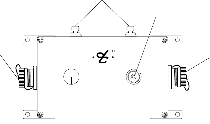
TheU9922‐G38(40995G‐01)3800Gatewayisafixed‐mountedwirelesscommunicationdevice
thatwhenusedinconjunctionwithoneormoreU9910‐BSW(40992G‐01)orU9912‐BSW
(40992G‐02)WirelessBeltStationsbecomespartofawirelessintercomsystem.TheU9922‐
G38providescommunicationforuptofourusersaswellasaninterfacetoanexistingDavid
ClarkModel3800wiredintercomsystem.Additionally,theU9922‐G38canbeusedasastand‐
alonewirelessintercomgatewaywithtwo‐wayradiointerface.Uptofourbeltstationscanbe
connectedtoonegateway.
Radio
Input
Status LED
VOLUME LINK
Antenna
System
Input R
Figure1:OverviewofGateway

3of9
I
In
ns
st
ta
al
ll
la
at
ti
io
on
n
IntercomInterface
TheU9922‐G38canbeconfiguredinoneoftwoways:3800interfaceandstand‐alone.
3800Interface
Thisconfigurationaddswirelesscapabilitytoanexisting3800wiredintercomsystemand
canreplaceaU3811orU3815radiointerfacemodule(see3800systemdocumentation
forfurtherdetails.)Inthisway,allwiredandwirelessusersmaycommunicatewitheach
otheraswellastalkoverandlistentoatwo‐wayradio.AC38‐xxsystemcableand
optionalC3821radiointerfacecablearerequiredforthisconfiguration.
Stand‐alone
Stand‐aloneconfigurationcreatesanad‐hocwirelessintercomandaddsaccesstoatwo‐
wayradio.Thisconfigurationdoesnotconnecttoa3800wiredintercomsystem.AC99‐
22PW(18748G‐24)powercableandoptionalC3821radiointerfacecablearerequiredfor
thisconfiguration.
Antenna
TheU9922‐G38hastwoexternalantennaconnectionsandissuppliedwithonewhipstyle
antenna.Inmostapplicationsasinglewhipantennaissufficient.Howevertheoptionalremote
antennakit(P/N:40688G‐93)isavailableshouldmorerangebedesired.Inthiscase,we
recommendkeepingonewhipantennaconnecteddirectlytotheU9922‐G38androutingthe
remoteantennasomewhereelse(suchasontheroofofavehicle).
Chooseanopen,clearlocationfortheremoteantennaandroutethecoaxialcableawayfrom
anybusyareas,preferablybehindpanelsorinconduits.
Thisdevicehasbeendesignedtooperatewiththeantennaslistedbelow,andhavinga
maximumgainof3dB.Antennasnotincludedinthislistorhavingagaingreaterthan3dBare
strictlyprohibitedforusewiththisdevice.Therequiredantennaimpedanceis50ohms.
Acceptableantennasforusewiththisproduct:
• WhipAntenna(P/N:40688G‐92)
• RemoteAntennaKit(P/N:40688G‐93)

4of9
L
Li
in
nk
ki
in
ng
g
Beforeabeltstationandagatewaycanbeconnected,theymustfirstbelinked.Asasecurity
measure,theclose‐linkfeaturerequiresdevicestobeinproximityofabout1to3ft(0.3to0.9m)
inordertosuccessfullylink.Thisensuresthattheunitsarenotinadvertentlylinkedwithother
unitsonthepremises.
Linkingprocedure:
1. Ensureunitsarewithin1to3ft(0.3to0.9m)ofeachother.
2. Simultaneously(within1‐2sec)pressandreleasetheLINKbuttonontheU9922‐G38and
thebeltstationtolinkwith.
3. AmberLED’swillflashquicklyonbothdevices.AmomentaryredLEDindicatesa
successfulclose‐link.
4. UponsuccessfullinktheU9922‐G38willattempttoestablishaconnectionwiththebelt
station.
5. UponsuccessfullyestablishingconnectiontheLEDonthegatewaywillflashagreen
patterncorrespondingtothenumberofbeltstationsconnected.
Tip:
Oncelinked,thedeviceswillnotneedtobelinkedagainunlesstheyarepurged(see
Purging).
Eachbeltstationisabletobelinkedtoonlyonegatewayatatime.Agatewaycanhaveuptosix
beltstationslinkedandbeconnectedtofourofthosesixatonetime.
S
St
ta
at
tu
us
s
I
In
nd
di
ic
ca
at
ti
io
on
ns
s
TheLINKbuttonhasamulti‐colorLEDinthecenterwhichservesasastatusindicationforthe
gateway.Table1belowliststhesestates.
Table1:LEDStatusIndications
LEDColorBlinkRateStatus
RedSolidInitializing/powerup
RedOnceConnectionDropped
RedOnceConnectionEstablished
RedAnyLowbattery(approx.1hrremaining)
OrangeSlowIdle/Disconnected
OrangeFastLinking/ConnectioninProgress
OrangeSolidPTTasserted
GreenSlowConnected(patternindicates
numberofbeltstationsconnected)

5of9
O
Op
pe
er
ra
at
ti
io
on
n
Communication
AllconnectedbeltstationswillbeabletocommunicatewitheachotherthroughtheU9922‐G38
whileinrange(andpertheVOXsettingsoneachVOXbeltstation.)Additionally,allbeltstation
userswillhavecommunicationovertheintercom.Ifatwo‐wayradioisinstalledtotheU9922‐
G38,pressingthePTTbuttononaVOXbeltstationwillallowtheusertotransmitoverthe
system’stwo‐wayradio.PressingthePTToverridestheVOXsettingonaVOXbeltstation.
MultiplebeltstationusersmayPTTandthusspeakoverthetwo‐wayradiosimultaneously.For
moreinformationconsulttheusermanualforthebeltstation.
Tip:
WirelessuserswhoarenotpressingPTTwhileanotherwirelessuserispressingPTTwill
notbeheardonthewiredintercomwhilethePTTremainspressed.
IntercomLevelAdjustment
Audiolevelscanvarybetweenintercoms,mainlyduetothesystemlevelsettingonthewired
intercom.Tocompensateforthis,theU9922‐G38hastheabilitytoadjustitsreceivelevelfrom
theintercomusingtheVolumeknob(seeFigure1).Turningthisknobwillincreaseordecrease
theaudiolevelcomingfromthewiredintercomintothegateway.Performthisadjustmentto
obtainoptimumperformance.
IntercomLevelAdjustmentProcedure
1. ConnectatleastonebeltstationtotheU9922‐G38gatewayandensuresidetoneis
present(seebeltstationUserManual).
2. BeginspeakingandslowlyturntheVolumeknobontheU9922‐G38clockwiseuntil
youhearanechoofyourownvoice.
3. ContinuespeakingandturntheVolumeknobcounter‐clockwiseuntiltheechostops.
4. Youmaywishtoverifycommunicationwithsomeonehard‐wiredtotheintercom.
RadioLevelAdjustment
Audiolevelstoandfromatwo‐wayradiocanalsovarybetweenradiomodelsand
manufacturers.ToadjusttheU9922‐G38foraparticularradio,followtheproceduresbelow.

6of9
RadioTransmitLevelAdjustmentProcedure
Note:Aradioservicemonitorisrecommendedforthisadjustment.
1. ConnectatleastonebeltstationtotheU9922‐G38gatewayandensuresidetoneis
present(seebeltstationUserManual).
2. OpenthecoveroftheU9922‐G38andfindthelargesilverknob.
3. PressandholdthePTTandspeakclearlyandloudlyintothemicrophone.
4. Slowlyturntheknobuntiltheradioservicemonitorreads4.0‐4.5kHzdeviation.
a. Clockwisetoincreaselevel;counter‐clockwisetodecrease
RadioReceiveLevelAdjustmentProcedure
1. ConnectatleastonebeltstationtotheU9922‐G38gatewayandensureside‐toneis
present(seebeltstationUserManual).
2. OpenthecoveroftheU9922‐G38andfindthelargesilverknob.
3. Tunetheradiotoacontinuoustransmission(suchasNWS)ortransmitatestsignal
fromanotherradio.
4. Adjustthevolumecontrolontheradiotoalevelslightlyhigherthantypical.
5. Slowlyturntheknobuntilyouhearaloudandclearsignalonthewirelessintercom.
a. Clockwisetoincreaselevel;counter‐clockwisetodecrease
Range
Therangeofabeltstationandagatewaycanbeupto300ft(100m).Ifyouareinan
environmentwithmetalorconcretewalls,thisrangecouldbereduced.Whenthebeltstation
travelsoutofrangeofthegateway,avoicealertwillindicatethattheconnectionhasbeenlost.
Toreconnect,simplymovebackintorangeandconnectionwiththegatewaywillautomatically
bereestablished,alsonotedbyavoicealert.
P
Pu
ur
rg
gi
in
ng
g
Insomecircumstancesitmaybenecessaryto“purge”theU9922‐G38ofsomeofitslinkedbelt
stations.Typicallypurgingisnotnecessaryunlesstherearemultiplegatewaysinthesame
vicinityandyouwishtoremoveabeltstationfromthisgatewayandlinktoadifferentgateway.
Agatewaycanlinkuptosixbeltstationswhereabeltstationcanbelinkedtoonlyonegateway
atatime.
SmartPurge
AsmartpurgeisthepurgemethodemployedfortheU9922‐G38,inwhichonlyunwantedlinks
areremovedfromthegateway.Whenthisprocedureiscomplete,onlybeltstationsthatare
connectedtothegatewayremainlinked.Allotherbeltstationlinkswillhavebeenremoved(see
thebeltstationUserManualfortheindividualbeltstationpurgingprocedurewhenremaining
linkpurgingmaybenecessary.)

7of9
SmartPurgeprocedure
1. Ensuregatewayispoweredonandfunctioning.
2. Disconnectallbeltstationstobepurged(poweroffthebeltstations).
3. VerifythenumberofgreenLEDflashesonthegatewaymatchesthenumberof
beltstationstobekeptlinked.
4. PressandholdLINKbuttononthegatewayfor30secondsuntilLEDquickly
flashesred.
5. ReleaseLINKbutton.
T
Tr
ro
ou
ub
bl
le
es
sh
ho
oo
ot
ti
in
ng
g
Table2:Troubleshooting
ProblemSolution
GatewaywillnotturnonReviewInstallationprocedure
Ensurewiringiscorrect.
CannotlinkabeltstationReviewLinkingprocedure
Ensureunitsarewithin1to3ft(0.3to0.9m)of
eachother
TryaSmartPurge
Cannotspeakovertwo‐way
radio
PTTnotpressed
NoradioconnectedtoU9922‐G38
R
Re
ep
pl
la
ac
ce
em
me
en
nt
t
P
Pa
ar
rt
ts
s
• Systemcable(C38‐xx;numberafterdashindicateslengthinfeet)
• PowerCable(C99‐22PW,P/N:18748G‐24)
• RadioInterfaceCable(C3821,P/N:18747G‐06)
• WhipAntenna(P/N:40688G‐92)
• RemoteAntennaKit(P/N:40688G‐93)
8of9
C
Ca
ar
re
e
a
an
nd
d
M
Ma
ai
in
nt
te
en
na
an
nc
ce
e
TheU9922‐G38isnotuserserviceable.Donotattempttoopentheenclosure(unlessadjusting
theradiolevelpertheproceduresnotedinthismanual.)Ifthisproductrequiresservice,please
contacttheDavidClarkCustomerServicedepartment:
• Phone: 800.298.6235
• E‐Mail:serviceWWW@DavidClark.com
• ByMail:CustomerService
DavidClarkCompany
360FranklinStreet
Worcester,MA01604
Ifnecessary,theU9922‐G38maybewipeddownwithamildsoapandwatermixture.Although
itisasealeddevicedesignedtowithstandsubmersioninwaterto1meter,donotunnecessarily
submersethisproductinwater.
Avoidstorageofthisproductindirectsunlightorhightemperatureenvironments.
S
Sp
pe
ec
ci
if
fi
ic
ca
at
ti
io
on
ns
s
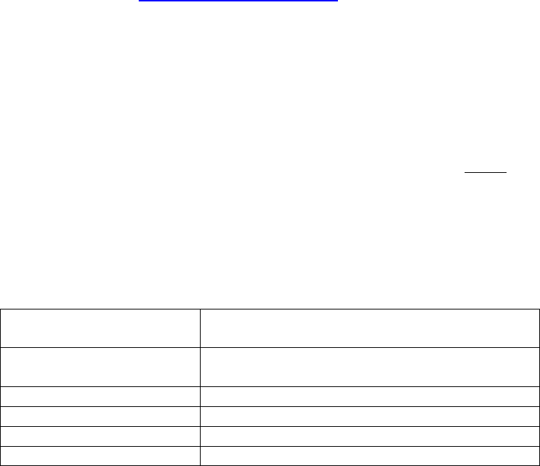
FrequencyRange1920MHz‐1930MHz(U.S.andCanada)
1880MHz‐1900MHz(EU)
AverageRFPowerOutput4mW(100mWpeak)(U.S.andCanada)
10mW(250mWpeak)(EU)
Range300ft(100m)line‐of‐sight(nominal)
OperatingTemperature‐14°Fto113°F(‐10°Cto+45°C)
StorageTemperature‐4°Fto140°F(‐20°Cto+60°C)
PowerRequirements8to32VDC
9of9
F
FC
CC
C
P
Pa
ar
rt
t
1
15
5
S
St
ta
at
te
em
me
en
nt
t
RADIOANDTELEVISIONINTERFERENCE
ThisequipmenthasbeentestedandfoundtocomplywiththelimitsforaClassBdigitaldevice,
pursuanttoPart15oftheFCCrules.Theselimitsaredesignedtoprovidereasonableprotection
againstharmfulinterferenceinaresidentialinstallation.Thisequipmentgenerates,usesandcan
radiateradiofrequencyenergyand,ifnotinstalledandusedinaccordancewiththeinstructions,
maycauseharmfulinterferencetoradiocommunications.However,thereisnoguaranteethat
interferencewillnotoccurinaparticularinstallation.Ifthisequipmentdoescauseharmful
interferencetoradioortelevisionreception,whichcanbedeterminedbyturningtheequipment
offandon,theuserisencouragedtotrytocorrecttheinterferencebyoneormoreofthe
followingmeasures:
‐Reorientorrelocatethereceivingantenna.
‐Increasetheseparationbetweentheequipmentandthereceiver.
‐Connecttheequipmentintoanoutletonacircuitdifferentfromthattowhichthereceiveris
connected.
‐Consultthedealeroranexperiencedradio/TVtechnicianforhelp.
Youmayalsofindhelpfulthefollowingbooklet,preparedbytheFCC:"HowtoIdentify
andResolveRadio‐TVInterferenceProblems."ThisbookletisavailablefromtheU.S.
GovernmentPrintingOffice,WashingtonD.C.20402.
*InordertomaintaincompliancewithFCCregulationsshieldedcablesmustbeusedwith
thisequipment.Operationwithnon‐approvedequipmentorunshieldedcablesislikelytoresult
ininterferencetoradio&televisionreception.
U
Un
na
au
ut
th
ho
or
ri
iz
ze
ed
d
C
Ch
ha
an
ng
ge
es
s
ChangesormodificationsnotexpresslyapprovedbyDavidClarkCompany,Inc.couldvoidthe
users’authoritytooperatetheequipment.
F
FC
CC
C
R
Ra
ad
di
ia
at
ti
io
on
n
E
Ex
xp
po
os
su
ur
re
e
S
St
ta
at
te
em
me
en
nt
t
ThisequipmentcomplieswithFCCradiationexposurelimitssetforthforanuncontrolled
environment.Thisequipmentshouldbeinstalledandoperatedwithaminimumdistanceof20
centimeters(8inches)betweentheradiator(antenna)andyourbody.Thistransmittermustnot
beco‐locatedoroperatinginconjunctionwithanyotherantennaortransmitter.
U
Us
sa
ag
ge
e
R
Re
es
st
tr
ri
ic
ct
ti
io
on
ns
s
DuetotheUPCSfrequenciesused,thisproductislicensedforoperationonlyintheUnitedStates
ofAmericaandCanada.