Davis Instruments DWW6326 ISS PLUS User Manual ISS FARS D014
Davis Instruments ISS PLUS ISS FARS D014
Manual
Draft 07/02/01 Product # 6151, 6151C, 6161, 6161C
F
AN
-A
SPIRATED
R
ADIATION
S
HIELD
For Vantage Pro
TM
or Vantage Pro Plus
TM
A
DDENDUM
TO
THE
I
NTEGRATED
S
ENSOR
S
UITE
I
NSTALLATION
M
ANUAL
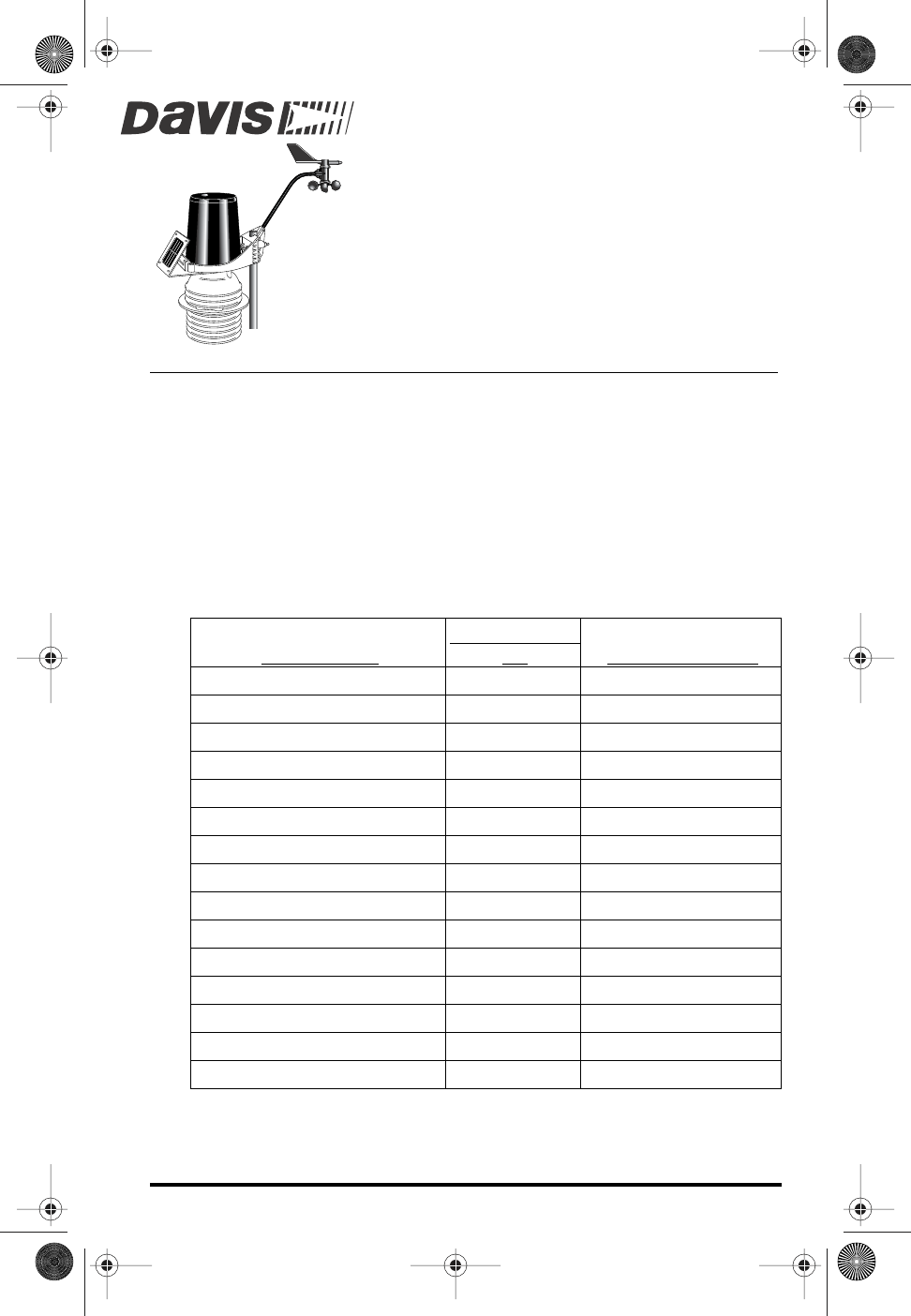
The Vatage Pro Integrated Sensor Suite (ISS) with the Fan-Aspirated Radiation
Shield uses a combination of fan-aspiration and passive shielding to minimize
the effects of solar radiation-induced temperature error.
Fan-Aspirated ISS Addendum Overview
This addendum provides additional information specific to the installation and
use of the fan aspirated radiation shield only, and is intended to be used in con-
juction with the “Integrated Sensor Suite Installation Manual.”
The Table below shows the location of the information required to install and
maintain your Fan-Aspirated ISS.
S
ECTION
/P
ROCEDURE
F
AN
A
SPIRATED
A
DDEN-
DUM
ISS I
NSTALLATION
M
ANUAL
Tools for Setup
X
Preparing the Anemometer
X
Disassembling the Radiation Shield
X
Making Terminal Block Connections
X
Powering ISS and Testing Communications
X
Powering and Testing the Fan
X
Reassembling the Radiation Shield
X
Preparing the Rain Collector
X
Choosing a Site for the ISS
X
Mounting the ISS
X
Additional Mounting Options
X
Fan-Aspirated ISS Options
X
Fan-Aspirated ISS Maintenance
X
Fan-Aspirated ISS Troubleshooting
X
Fan-Aspirated ISS Specifications
X
ISS FARS D014 Page 1 Thursday, July 5, 2001 4:18 PM
Page 2 Draft 7/5/01 Fan-Aspirated Radiation Shield
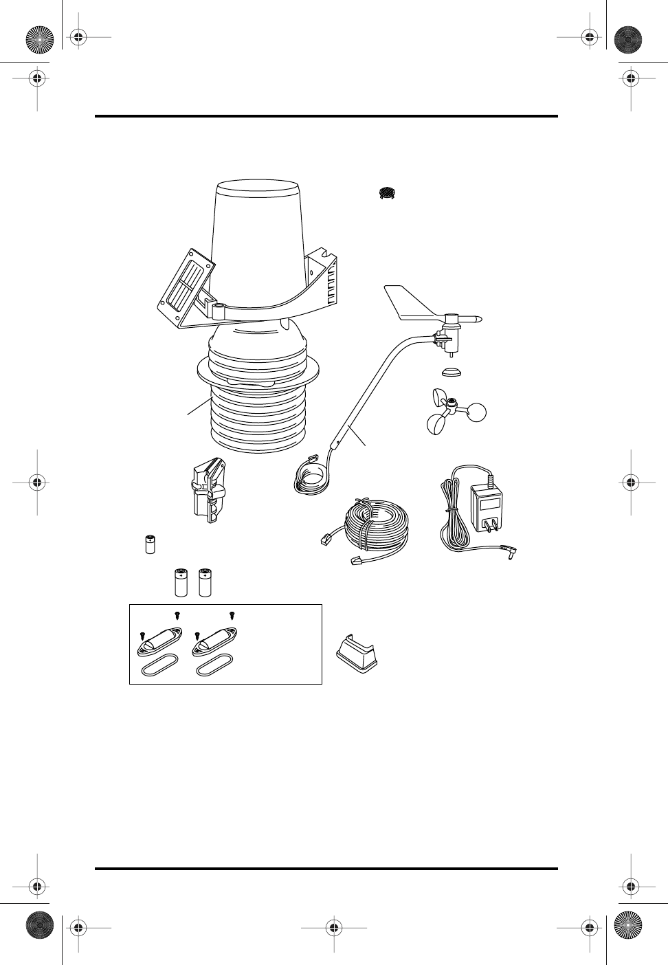
Components
The Fan-Aspirated ISS includes these components:
Solar
Panel
(wireless
models
only)
Aspirated
Radiation Shield
Debris Screen
(place inside
rain collector cone
after installation)
Anemometer
Base
Anemometer
Arm
40 feet
(12.2 meter)
Anemometer
Cable
Anemometer
Vane
Drip Ring
Wind Cups
100 feet
(30 meter)
Standard 4-Conductor
Cable
110 Volt AC
Power Adapter
(cabled models
only)
1.2 Volt Nicad
Batteries
3 Volt Lithium
Battery
#4 Self-Threading
Screws (2)
Battery Covers (2)
O-Rings (2)
Junction Board
Cover
ISS FARS D014 Page 2 Thursday, July 5, 2001 4:18 PM
Draft 7/5/01 Page 3
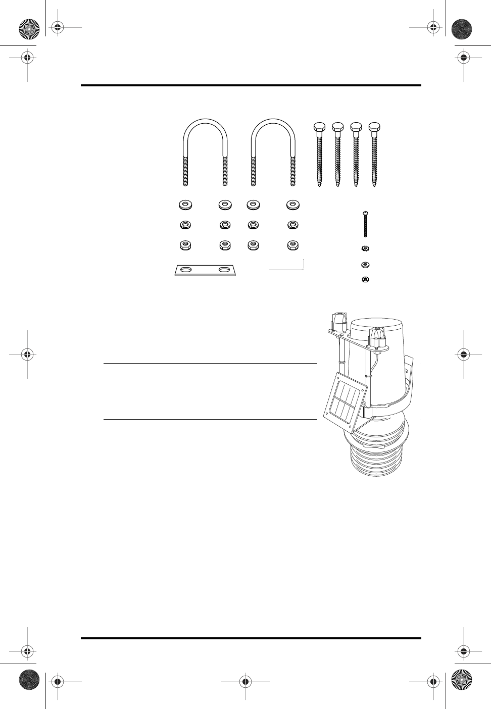
The hardware shown here is provided for assembly and mounting:
Additional Components on Vantage Pro
Plus
Vantage Pro
Plus
includes an ultraviolet (UV) sen-
sor and a solar radiation sensor. These two sensors
are on the rain collector side of your ISS.
Note:
Please make every effort when handling your ISS not to touch
the small white diffusers on top of the UV and solar radiation
sensors. Oil from the skin will reduce their sensitivity. Clean the
diffusers using ethyl alcohol on a soft cloth (NOT rubbing alco-
hol).
Tools for Installation
Refer to this section in your ISS Installation Manual.
Preparing the Anemometer
Refer to this section in your ISS Installation Manual.
Disassembling the Radiation Shield
The radiation shield must be disassembled in order to make necessary cable
connections and to install batteries in the wireless version of the ISS, which is
solar powered.
1/4" Flat Washers
1/4" Lock Washers
1/4" Hex Nuts
U-Bolts
Nut Plate .05"
Allen Wrench
1/4" x 3" Lag Screws
#4 x 1-1/8"
Machine Screw
#4 Tooth
Lock Washer
#4 Flat
Washer
#4-40
Hex Nut
Vantage Pro Plus ISS
ISS FARS D014 Page 3 Thursday, July 5, 2001 4:18 PM
Page 4 Draft 7/5/01 Fan-Aspirated Radiation Shield
The ISS sensors are connected by cables to the
Sensor Interface Module
(SIM),
located inside the radiation shield. The SIM contains electronics which mea-
sure and store weather values for transmission to the console via cable or radio
waves. The radiation shield’s white plastic plates protect the SIM from sun and
other sources of radiated and reflected heat, and from precipitation.
Before installing the ISS, the radiation shield must be disassembled in order to
perform the following tasks:
✦
Verify that the rain sensor cable is connected to the SIM
✦
Connect the anemometer sensor cable to the SIM
✦
Connect the console cable to the SIM (cabled versions only)
✦
Make power connections to the ISS
✦
Install batteries in the SIM and Fan Plate (wireless versions only)
✦
Change the transmitter ID for wireless communication, if necessary
✦
Verify that your console is receiving and displaying data
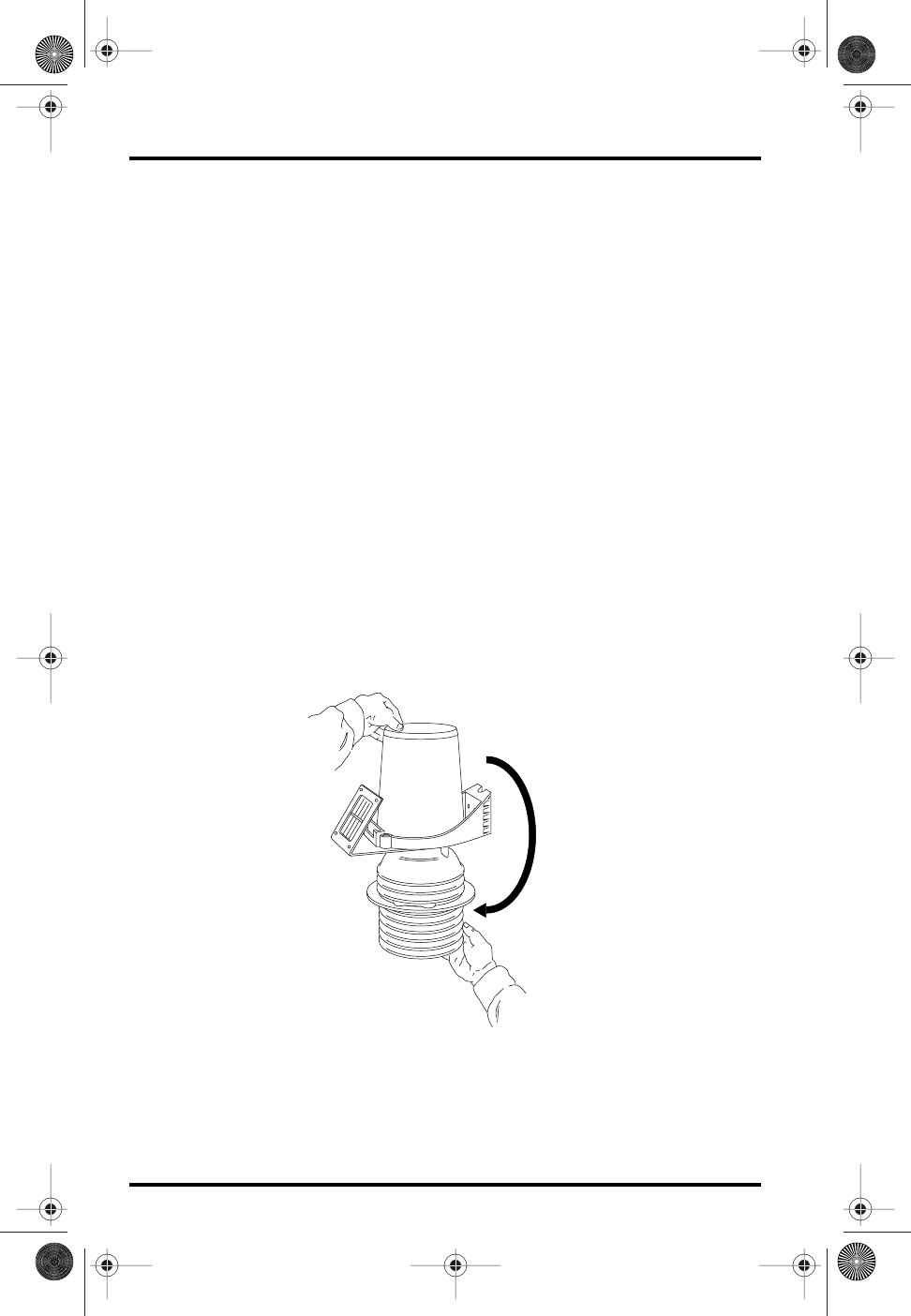
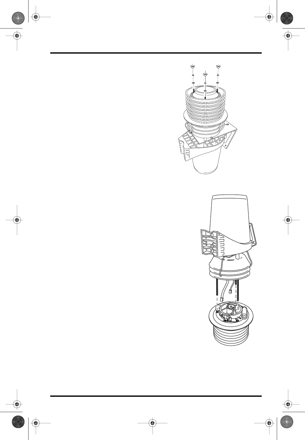
Opening the Radiation Shield
Open up the radiation shield by separating the top and bottom parts as shown
in the following illustrations.
1.
Turn the rain collector side of the ISS upside down.
Hold plates
while inverting
Inverting the ISS
ISS FARS D014 Page 4 Thursday, July 5, 2001 4:18 PM
Disassembling the Radiation Shield Draft 7/5/01 Page 5
2.
Remove the three wing nuts, lock
washers and flat washers located on
the underside of the radiation shield.
3.
Turn the ISS right-side up with the
rain collector on top.
4.
Hold onto the rain collector and left
off the top part of the ISS, exposing the
fan plate on the bottom part of the radia-
tion shield.
#8 Wing Nuts
#8 Lock Washers
#8 Flat Washers
Removing the Wing Nuts
Integrated
Sensor
Suite
Fan
Aspirated
Radiation
Shield
Separating the Radiation Shield
ISS FARS D014 Page 5 Thursday, July 5, 2001 4:18 PM
Page 6 Draft 7/5/01 Fan-Aspirated Radiation Shield
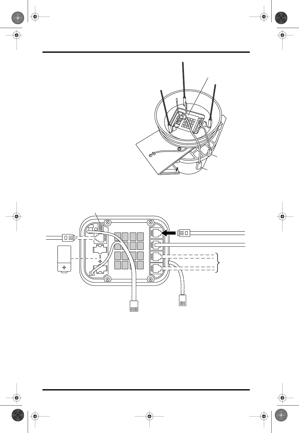
Verifying Sensor
Connections:
1.
Locate the SIM inside
the radiation shield.
2.
Verify that the rain sen-
sor cable is plugged into
the receptacle labeled
“RAIN” on the SIM.
3.
If you have a Vantage
Pro Plus, verify that the
UV and solar radiation
sensors are plugged into
the SIM.
Connecting Anemometer to SIM
Refer to this section in your ISS Installation Manual.
Cabled Vantage Pro: Powering the ISS and Testing Com-
munication with the Console
Refer to this section in your ISS Installation Manual.
Sensor Interface
Cable
Solar Power
Cable
(wireless
models only)
Sensor Interface
Module
Locating the ISS SIM
3-Volt
Lithium Battery
(wireless models
only)
Console Cable
(cabled
models only)
Transmitter
ID Switches
Anemometer Cable
UV Sensor Cable
Solar Radiation Cable
Rain Collector Cable (factory installed)
(factory
installed
on Pro Plus
models)
WIND RAIN SOLAR UV
Solar Power
Cable
(wireless models only)
Sensor Interface
Cable
ISS SIM Connectionsl
ISS FARS D014 Page 6 Thursday, July 5, 2001 4:18 PM
Cabled Vantage Pro: Powering the Fan Draft 7/5/01 Page 7
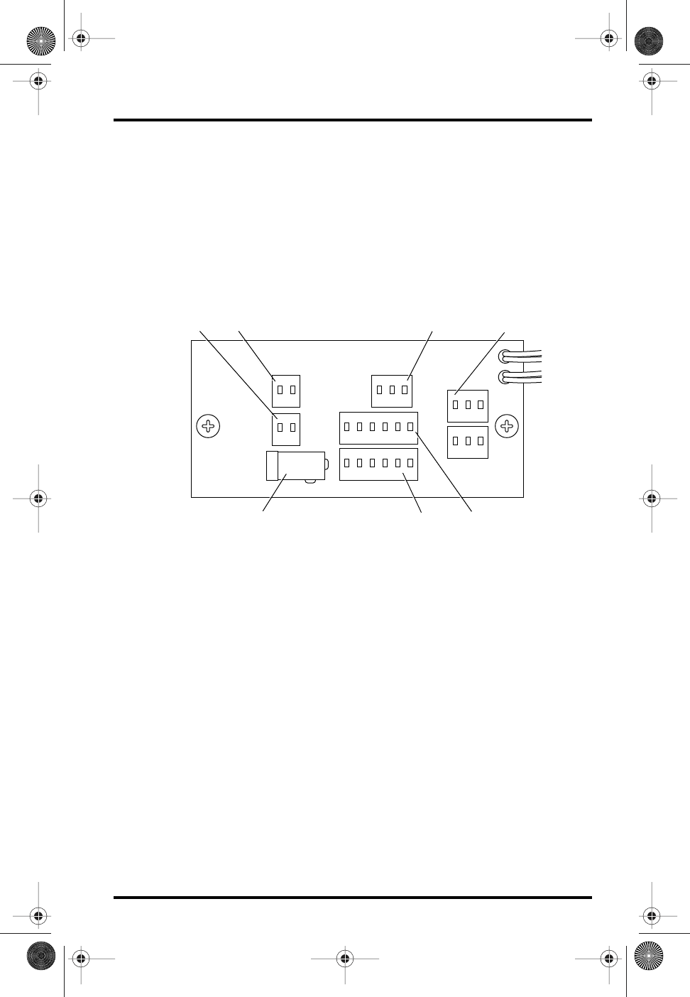
Cabled Vantage Pro: Powering the Fan
1.
Locate the Junction Board on the fan plate.
2.
Connect the AC-power adapter to the +5V connector on the Junction
Board.
3.
Plug the AC-power adapter into an AC outlet.
4.
Check to see that the fan is turning.
5.
Unplug the AC power adapter from the AC outlet until it has been
mounted.
6.
Secure the AC power cable to the fan plate with the supplied cable clip.
Wireless Vantage Pro: Powering the ISS and Testing
Communication with the Console
Refer to this section in your ISS Installation Manual.
+VSIM MOTOR
+VSIM
+VSOL
+5V
T/H & SIM
TACH
Solar and SIM Power Connectors (Wireless Only) Fan Connector Not used
AC Power Adapter Connector
(Cabled Only)
Temp Sensor
Connector
Sensor Interface
Module Connector
Junction Board Connections
ISS FARS D014 Page 7 Thursday, July 5, 2001 4:18 PM
Page 8 Draft 7/5/01 Fan-Aspirated Radiation Shield
Wireless Vantage Pro: Powering the Fan
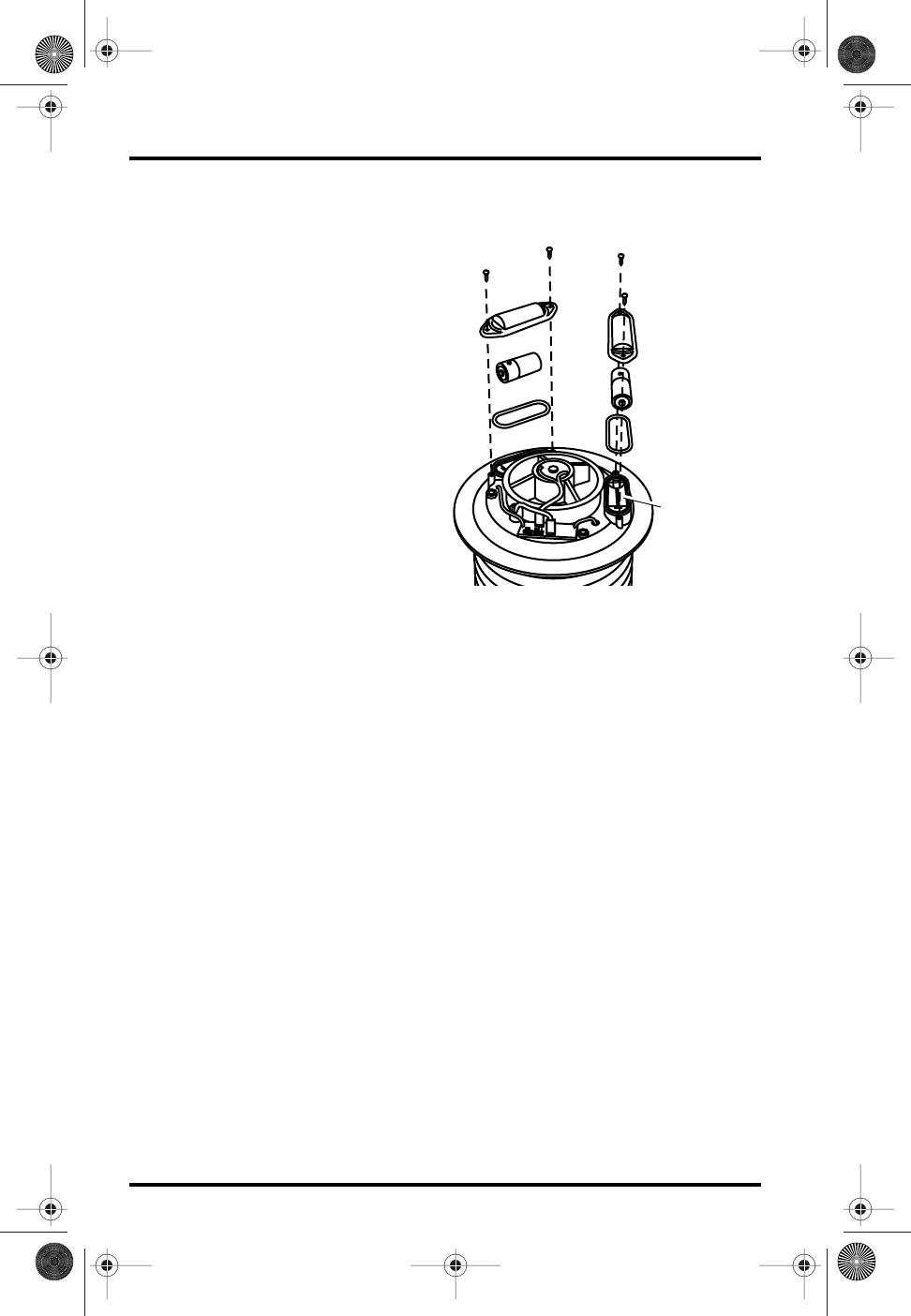
Installing the Batteries
1.
Insert the O-ring in the groove
around the edge of each bat-
tery compartment.
2.
Insert a NiCad battery in each
compartment, matching the
plus sign on the battery with
the plus sign in the battery
compartment.
3.
Verify that the fan is working.
4.
Remove the batteries unless
you are ready to install the
ISS in it’s final location. Oth-
erwise, the batteries will dis-
charge from powering the
fan.
5.
Attach the battery covers to the
battery compartments using
two #4 x 3/8” (9.5 mm)
screws each.
Reassembling the Radiation Shield
1.
Check all SIM and Junction Board cable connections.
2.
Install the Junction Board Cover as show below.
3.
Place the flat washers, lock washers and plastic wing nuts over the studs.
4.
Finger-tighten the wing nuts until they hold the radiation shield plates
firmly in place.
Preparing the Rain Collector
Refer to this section in your ISS Installation Manual.
Choosing a Site for the ISS
Refer to this section in your ISS Installation Manual.
Mounting the ISS
Refer to this section in your ISS Installation Manual.
Additional Mounting Options
Refer to this section in your ISS Installation Manual.
#4 Screws
Battery Cover
1.2 Volt Nicad
Battery
O-Ring
Battery
Compartment
Installing the Batteries
(Wireless Vantage Pro Only)
ISS FARS D014 Page 8 Thursday, July 5, 2001 4:18 PM
Fan-Aspirated ISS Options Draft 7/5/01 Page 9
Fan-Aspirated ISS Options
Low-Current Fan Unit
The optional low-current fan unit uses less power than the standard fan. This
allows the solar-powered Fan-Aspirated ISS to run for a longer period of time
during low-light conditions. It is recommended for use in extreme latitudes
during the Winter months, in climates that experience extended periods of
cloudy weather, or for any location with limited solar exposure.
Fan-Aspirated ISS Maintenance
✦
Keep the surfaces clean as the Fan-Aspirated Radiation Shield is less effective
when the surfaces are dirty. Remove dust from the solar panel and the screen
with a damp cloth.
✦
Remove any debris that obstructs air flow between the radiation shield parts e.g.,
leaves, twigs, webs, and nests.
✦
Avoid spraying insect killer of any kind into the radiation shield as this may dam-
age the sensors and the shield.
✦
Change the battery annually (solar models only) and also remove any debris
lodged inside the unit at this time.
Replacing Batteries
1.
Retrieve your Fan-Aspirated ISS and place on a stable work surface.
2.
Disassemble the Radiation Shield (See page 3).
3.
Remove the old battery
4.
Install a new battery
5.
Assemble the Radiation Shield (See page 8).
6. Mount the Fan-Aspirated ISS in it’s previous location.
ISS FARS D014 Page 9 Thursday, July 5, 2001 4:18 PM
Page 10 Draft 7/5/01 Fan-Aspirated Radiation Shield
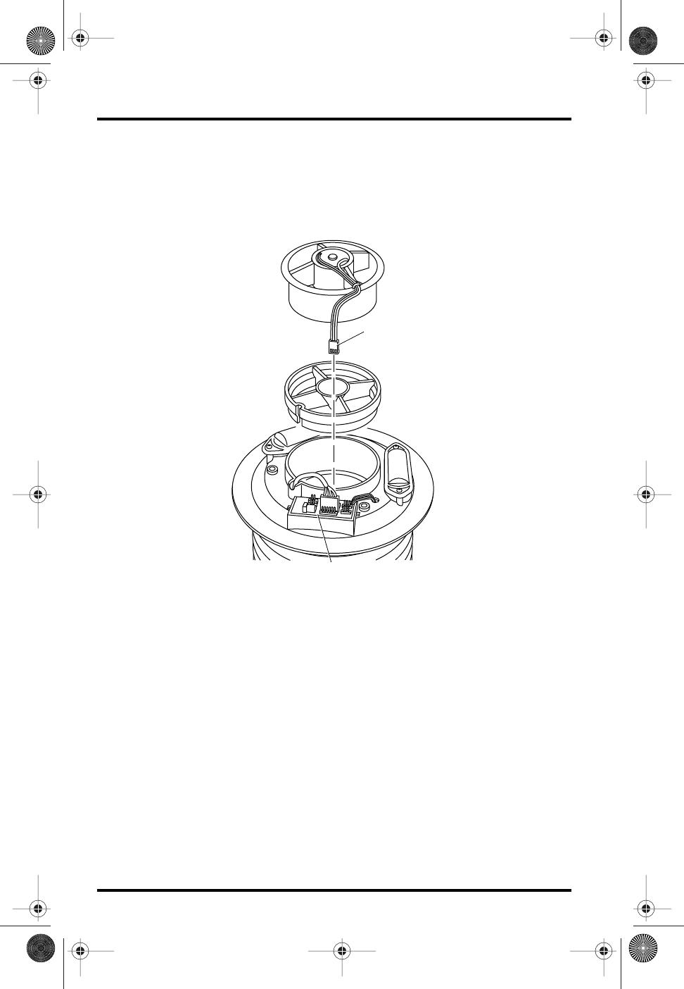
Replacing the Motor
1. Retrieve your Fan-Aspirated ISS and place on a stable work surface.
2. Disassemble the Radiation Shield (See page 3).
3. Remove the Junction Board Cover.
4. Lift the Fan Unit from the Radiation Shield.
5. Unplug the Motor Connector from the Junction Board.
6. Install the replacement motor in the Radiation Shield.
7. Plug the Motor Connector into the Motor Terminal on the Junction Board.
8. Assemble the Radiation Shield (See page 8).
9. Mount the Fan-Aspirated ISS in it’s previous location.
Fan Unit
Fan Deflector
Motor Connector
Junction Board
ISS FARS D014 Page 10 Thursday, July 5, 2001 4:18 PM
Fan-Aspirated ISS Troubleshooting Draft 7/5/01 Page 11
Fan-Aspirated ISS Troubleshooting
If you are unable to solve a problem with your Fan-Aspirated Radiation Shield,
please call Davis Technical Support. We’ll be glad to help. Most questions can
be answered while you’re on the phone. You can also email us for support, or
visit our website. Sorry, we are unable to accept collect calls.
Contacting Davis Instruments
(510) 732-7814 for Technical Support, Monday – Friday, 7:00 a.m. – 5:30 p.m.
Pacific Time.
(510) 732-9229 For callers outside the USA or Canada.
(510) 670-0589 Fax to Customer Service or Tech Support.
www.davisnet.com Copies of User Manuals are available on the “Support”
page. Watch for FAQs and other updates. Subscribe to the e-newsletter.
support@davisnet.com E-mail to Technical Support.
sales@davisnet.com E-mail to Customer Service.
info@davisnet.com General e-mail.
Note: Please do not return items to the factory for repair without prior authorization.
Fan-Aspirated ISS Specifications
Aspiration Rate . . . . . . . . . . . . . . . . . . . . . . . . . 215 feet/min. (1.1 m/s)
Radiation-Induced Temperature Error . . . . . . . . 0.5°F (0.3°C)
[At solar noon, insolation = 1040 W/m2]
(Reference: RM Young model 43408)
Note: The above error specification is an estimate, based on data from a solar-powered model,
which has a measured error of 0.6°F at the above conditions and an aspiration rate of 190 ft/
min vs. the rate of 215 ft/min in model 7750.
Temperature range . . . . . . . . . . . . . . . . . . . . . . –40 to 140° Fahrenheit (–40 to 60°
Celsius)
ISS Primary Power Input
Wireless ISS . . . . . . . . . . . . . . . . . . . . . . . . . . . solar panel
Cabled ISS . . . . . . . . . . . . . . . . . . . . . . . . . . . . receives power from Vantage Pro Console
ISS secondary power (Wireless Only) . . . . . . . . . CR-123A 3-volt lithium battery (approx.
two years battery life.)
Fan Primary Power Input
Wireless ISS . . . . . . . . . . . . . . . . . . . . . . . . . . . solar panel
Cabled ISS. . . . . . . . . . . . . . . . . . . . . . . . . . . . . AC power adapter, 5VDC, 200 mA,
regulated
Fan secondary power (Wireless Only) . . . . . . . . 1 or 2 - 1.2 Volt NiCad C-cells
ISS FARS D014 Page 11 Thursday, July 5, 2001 4:18 PM
Draft 07/02/01
Product Numbers: 6151, 6151C, 6161, 6161C
Davis Instruments Part Number: 7395.152
Fan-Aspirated Radiation Shield Addendum to the Integrated Sensor Suite Installation Manual
Draft Manual (7/2/01)
Copyright ©2001 Davis Instruments Corp. All rights reserved.
3465 Diablo Avenue, Hayward, CA 94545-2778
510-732-9229 • Fax: 510-732-9188
E-mail: info@davisnet.com • www.davisnet.com
FCC Part 15 Class B Registration Warning
This equipment has been tested and found to comply with the limits for a class B digital device,
pursuant to Part 15 of the FCC Rules. These limits are designed to provide reasonable protec-
tion against harmful interference in a residential installation. This equipment generates, uses
and can radiate radio frequency energy and, if not installed and used in accordance with the
instructions, may cause harmful interference to radio communications. However, there is no
guarantee that interference will not occur in a particular installation.
If this equipment does cause harmful interference to radio or television reception, which can
be determined by turning the equipment off and on, the user is encouraged to try to correct
the interference by one or more of the following measures:
✦Reorient or relocate the receiving antenna.
✦Increase the separation between the equipment and receiver.
✦Connect the equipment into an outlet on a circuit different from that to which
the receiver is connected.
✦Consult the dealer or an experienced radio/TV technician for help.
Changes or modifications not expressly approved in writing by Davis Instruments may void the
user's authority to operate this equipment.
ISS FARS D014 Page 12 Thursday, July 5, 2001 4:18 PM