Davis Instruments DWW6357 Weather Station Transmitter User Manual
Davis Instruments Weather Station Transmitter
Users Manual

Integrated Sensor Suite Installation Manual
Rev. A, May 14, 2009
Document Part Number: 07395.262
For Vantage Vue Weather Stations and Systems
Vantage Vue® is a trademark of Davis Instruments Corp., Hayward, CA.
© Davis Instruments Corp. 2009. All rights reserved.
Information in this document subject to change without notice
.
3465 Diablo Avenue, Hayward, CA 94545-2778 U.S.A.
510-732-9229 • Fax: 510-732-9188
E-mail: info@davisnet.com • www.davisnet.com
FCC Part 15 Class B Registration Warning
This equipment has been tested and found to comply with the limits for a Class B digital device, pursuant to Part 15
of the FCC Rules. These limits are designed to provide reasonable protection against harmful interference in a res-
idential installation. This equipment generates, uses, and can radiate radio frequency energy and, if not installed
and used in accordance with the instructions, may cause harmful interference to radio communications.
However, there is no guarantee that interference will not occur in a particular installation. If this equipment does
cause harmful interference to radio or television reception, which can be determined by turning the equipment on
and off, the user is encouraged to try to correct the interference by one or more of the following measures:
• Reorient or relocate the receiving antenna.
• Increase the separation between the equipment and receiver.
• Connect the equipment into an outlet on a circuit different from that to which the receiver is connected.
• Consult the dealer or an experienced radio/TV technician for help.
Changes or modification not expressly approved in writing by Davis Instruments may void the warranty and void
the user's authority to operate this equipment.
FCC ID: IR2DWW6357
IC: 3788A-6357
EC EMC Compliance
This product complies with the essential protection requirements of the EC EMC Directive 2004/108/EC; Low
Voltage Directive 2006/95/EC; and Eco-Design Directive 2005/32/EC >.5 watt no-load adaptor.

i
Table of Contents
Introduction ..................................................................................................... 1
Included Components and Hardware .........................................................1
Vantage Vue ISS Components ..........................................................1
Hardware .............................................................................................2
Tools for Setup .....................................................................................2
Preparing the ISS for Installation .........................................................2
Attaching the Wind Cups to the Anemometer ...............................3
Mounting the Wind Vane ..................................................................4
Installing the Debris Screen ...............................................................5
Installing the Rain Collector Tipping Spoon Assembly ................5
Applying Power to the ISS and Verifying Communication with the
Vantage Vue Console .........................................................................6
Apply Power to the ISS ................................................................6
Confirm the Transmitter ID of the ISS .......................................7
Set a New Transmitter ID on the ISS ..........................................7
Verifying Data from the ISS Sensors ................................................8
Confirming Rain Display Function on the Console .......................8
Choosing a Location for the ISS ...........................................................8
General ISS Siting Guidelines ............................................................9
Siting Guidelines that may Affect the Anemometer................ 9
Installing the ISS ........................................................................................... 10
General ISS Installation Guidelines ...................................................10
Installation Instructions ...............................................................................11
Finishing the Installation ....................................................................12
Maintenance and Troubleshooting ............................................................ 13
Maintenance ..........................................................................................13
Troubleshooting ...................................................................................15

ii
1
Introduction
The Vantage VueTM Wireless Integrated Sensor Suite (ISS) collects outside weather
data and sends the data wirelessly to a Vantage Vue console via a low-power radio.
The ISS is solar powered and includes a battery back-up.
The Vantage Vue ISS contains a rain collector, temperature/humidity sensor,
anemometer, and wind vane. The outside temperature/humidity sensors are
mounted in a passive radiation shield to minimize the impact of solar radiation on
sensor readings. The anemometer measures wind speed, and the wind vane
measures wind direction. See “Choosing a Location for the ISS” on page 8 for siting
guidelines.
The Sensor Interface Module (SIM) is housed within the ISS and comprises the
“brains” of the Vantage Vue system and the radio transmitter. The SIM collects
outside weather data from the ISS sensors and transmits that data to your Vantage
Vue console.
Note: Your Vantage Vue ISS can transmit to an unlimited number of consoles, so you can purchase additional
consoles to use in different rooms. It can also transmit to Vantage Pro2 consoles as well as Vantage Vue
consoles.
Included Components and Hardware
The ISS comes with all the components and hardware shown in the following two
illustrations.
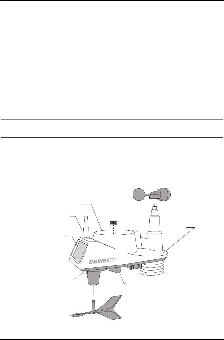
Vantage Vue ISS Components
Wind Vane
Anemometer
Wind Cups
Debris
Screen
Radiation
Shield
Rain
Collector
Solar Panel
ISS Cover
SIM Antenna
Tipping Spoon
Module (Rain)
ISS Base
2
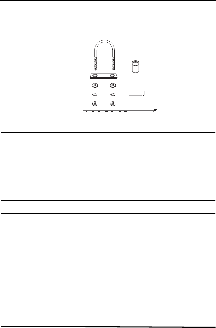
Hardware
The following hardware is included with the Vantage Vue ISS weather station
assembly. Some of the hardware is optional based on how the ISS is assembled and
installed. (See “Installing the ISS” on page 10 for more information.)
Note: If any of the hardware components are missing or not included, contact Customer Service toll free at 1-
800-678-3669 about receiving replacement hardware or other components.
Tools for Setup
The following are additional tools required to set up and install the ISS:
• Adjustable wrench or 7/16" wrench
• Compass or local area map
Preparing the ISS for Installation
Please follow the steps in the order in which they are presented. Each step builds on
tasks completed in previous steps.
Note: Davis Instruments recommends that you use a clean, well-lit work table or work area to prepare the ISS
for installation.
The steps to prepare the ISS for installation are:
• Attaching the wind cups to the anemometer
• Mounting the wind vane
• Installing the debris screen
• Installing the rain collector tipping spoon assembly
• Installing the ISS battery and testing communication with the Vantage Vue con-
sole
• Changing the Transmitter ID for wireless communication, if necessary
1/4" Flat Washers
1/4" Lock Washers
1/4" Hex Nuts
3-Volt
Lithium
Battery
U-Bolt
Back i ng Pl at e
0.05" Allen
Wrench
8" Cable Tie
Preparing the ISS for Installation
3
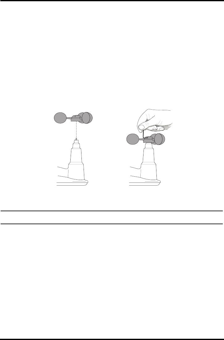
Attaching the Wind Cups to the Anemometer
The Vantage Vue anemometer measures wind speed. The wind cups are mounted on
the anemometer shaft on the top of the ISS assembly below.
To mount the wind cups on the anemometer shaft, follow these steps:
1. Gently slide the wind cup assembly down onto the anemometer’s stainless steel
shaft as far as it will go, as shown below.
2. Use the Allen wrench provided to tighten the set screw near the top of the “hub”
section of the wind cups, as shown below. Ensure that the set screw is screwed in
fully and is very tight.
3. Pull gently on the hub to ensure that the anemometer is securely fastened to the
shaft.
4. Spin the wind cups to make sure they spin freely.
Note: If the wind cups don’t spin freely, loosen the set screw, remove them from the shaft, and repeat the wind
cup installation process.
Install cups onto
stainless steel
shaft.
Tighten set screw
with Allen wrench.
4
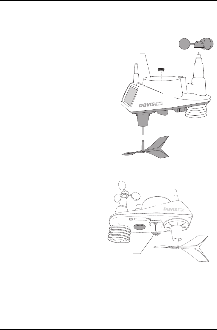
Mounting the Wind Vane
The Vantage Vue wind vane measures wind direction. The wind vane is mounted on
a stainless steel shaft on the opposite side of the ISS assembly from the anemometer
wind cups, as shown in the figure below.
To mount the wind vane on the wind vane shaft, follow these steps:
1. Grasp the ISS assembly so that you are looking at the underside of the assembly.
Hold it so that the anemometer and radiation shields are on your left and the wind
vane shaft is on the right, as shown below.
2. Carefully tip the ISS assembly so that it is “on its side” and the wind cups are away
from you.
When the ISS is held in this manner, the wind vane shaft is horizontal, and will ori-
ent itself so that its flat side will be facing to the right, as shown above.
3. Holding the ISS assembly with your left hand, grasp the wind vane with your right
hand so that the “arrowhead” end is pointed down.
4. Gently slide the wind vane onto the wind vane shaft, rotating the wind vane
slightly left and right if necessary, until the end of the wind vane shaft is visible
and flush with the bottom surface of the wind vane.
5. Secure the wind vane to the shaft by firmly tightening the wind vane set screw. Use
the Allen wrench that is shipped with your Vantage Vue ISS.
Orientation of
wind vane shaft
when held horizontal
Preparing the ISS for Installation
5
Installing the Debris Screen
The Vantage Vue ISS rain collector debris screen captures foreign matter or other
debris that may otherwise clog your rain collector and adversely affect the accuracy
of your rainfall measurements.
To install your debris screen, follow
these steps.
1. Locate the small black plastic ISS
debris screen in your hardware
package.
The debris screen has four small
tabs that hold it in place in the base
of the rain collector.
2. Holding the ISS assembly with one
hand, and holding the debris screen
by the tab, press the screen into the
opening at the bottom of the rain
collector until you feel and hear the
tabs snap into the opening.
The screen will now be held
securely in the rain collector.
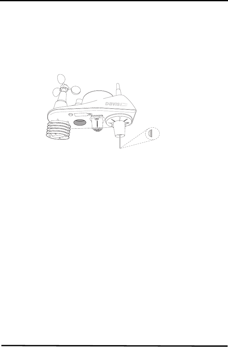
Installing the Rain Collector Tipping Spoon Assembly
To install the Tipping Spoon
Assembly, follow these steps:
1. Locate the Tipping Spoon
Assembly slot on the underside
of the ISS Base, as shown in the
drawing below.
2. Insert the wider end of the Tip-
ping Spoon Assembly into the
slot first, sliding it under the lip
of the slot.
3. Tighten the thumbscrew
securely.
Debris
Screen
Rain
Collector
T
ipping Spoon
Module
6
Applying Power to the ISS and Verifying Communication with the Van-
tage Vue Console
The ISS maintains a wireless connection to a Vantage Vue console when the ISS is
powered and a wireless communication channel has been established between the ISS
and the console. Follow the steps below for powering the ISS and establishing a
connection to the console.
• Apply power to your Vantage Vue ISS
• Verify communications with the console
• Verify data is being transmitted from the ISS sensors
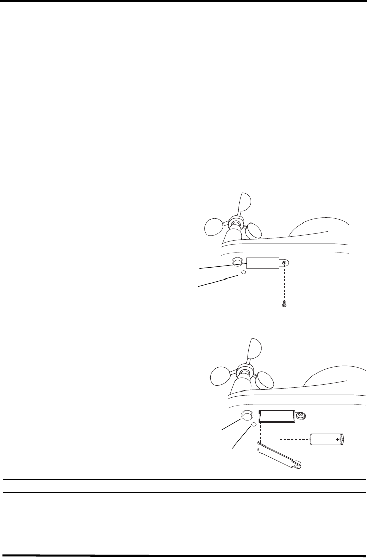
Apply Power to the ISS
The Vantage Vue ISS SIM board stores energy from the solar panel for power at night.
A 3-volt lithium battery is used as a backup power source. The battery compartment
cover is located on the underside of the ISS base, as shown in the figure below.
To install the ISS backup battery, follow these steps.
1. Unscrew the
thumbscrew securing
the battery compartment
cover as shown
2. Insert the 3-volt lithium
battery into the ISS bat-
tery compartment, as
shown below, being sure
to match the “+” sign on
the battery with the “+”
sign embossed on the
inside of the battery
compartment.
3. Ensure that the battery is firmly
installed, replace the battery
compartment cover, and tighten
the thumbscrew.
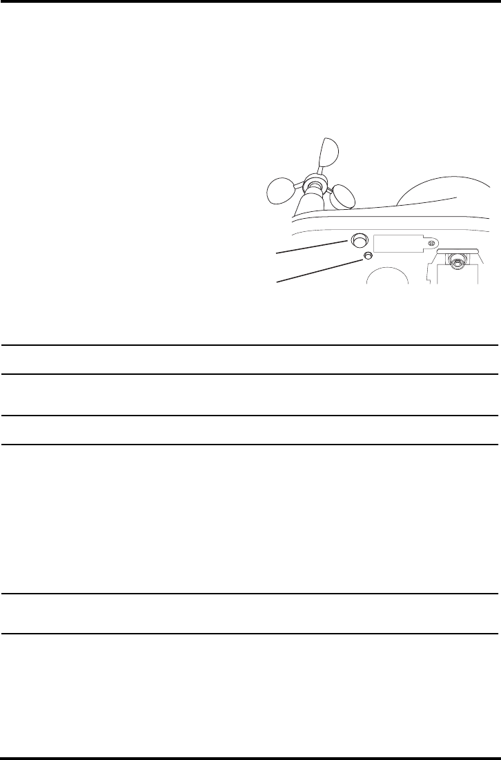
To verify power, push and
release the white Transmitter ID
button next to the Battery Com-
partment. The green Transmit-
ter ID LED next to the Battery
Compartment will illuminate
when you press the button.
Note: Push the button once and release it. Do not push it multiple times or hold it down
When you release the button, it will blink one time every 2.5 seconds to show
transmission of a data packet. This blinking will stop within a few minutes to con-
serve battery life.
4. Wait five minutes for console to acquire the radio signal and pouplate data fields.
Battery
compartment
cover
Green
LED
Transmitter ID
LED
Transmitter ID
pushbutton
Preparing the ISS for Installation
7
Confirm the Transmitter ID of the ISS
In order to communicate, the console and ISS must have the same Transmitter ID. At
the factory, both IDs are set at a default of number 1. If you need to confirm the Trans-
mitter ID of your Vantage Vue ISS, follow these steps.
Looking at the underside of your Vantage Vue ISS, locate the Transmitter ID Pushbut-
ton and the Transmitter ID LED, as shown in the figure below.
1. Push the Transmitter ID
Pushbutton once.
2. Note the number of times
Transmitter ID LED
blinks.
Unless you have inten-
tionally changed your
transmitter ID, the LED
should blink one time
because the default Trans-
mitter ID for the ISS is
“1.” If you have changed the ID, the LED should blink the number of times equal
to the ID you have set (i.e., twice for an ID of ‘2,’ three times for an ID of ‘3,’ etc.).
Note: The transmitter on the ISS and receiver on the console will communicate with each other only when both
are set to the same Transmitter ID.
Set a New Transmitter ID on the ISS
Note: In most cases, it will not be necessary to change the Transmitter ID. If it is necessary to change the Trans-
mitter ID, you must use the same ID for the ISS and console.
To set a new transmitter ID, follow these steps.
1. Push and hold the Transmitter ID button until the LED begins blinking quickly.
2. Release the button, and the LED will stop blinking.
3. Push the button the number of times equal to your desired new transmitter ID.
That is, if you want to change the ID to ‘3,’ push the button three times, and for a
desired ID of ‘4,’ push the button four times.
After four seconds have elapsed with no further presses, the LED will blink the
same number of times as the new transmitter ID.
Note: If you hold the button too long and accidentally enter the “set new transmitter ID” mode when you did not
want to, simply release the button and wait four seconds. As long as you do not press the button again,
the original transmitter ID will remain in effect.
T
ransmitter ID
Button
Transmitter ID
LED

8
Verifying Data from the ISS Sensors
Use these steps to verify reception of ISS data at the wireless Vantage Vue console and
to test the operation of the ISS sensors.
1. If the console is in Setup Mode, press and hold DONE until the Current Weather
screen displays.
Sensor readings from the ISS should display on the screen within a few minutes.
2. At the top right corner of the screen, look for the outside temperature.
3. Gently spin the wind cups to check wind speed, pressing WIND if necessary to
alternate between speed and direction in the compass rose.
4. Gently turn the wind vane, and allow 5 seconds for the wind direction display to
stabilize before moving it again.
Approximately one minute after acquisition of the signal, the outside relative
humidity reading should be displayed on the console, below the outside tempera-
ture display.
5. Current weather data displayed on the console confirms successful communica-
tion.
Confirming Rain Display Function on the Console
You can perform this procedue either inside over a sink or outside. You will need
your powered-up console as well as the ISS.
1. On your console screen, select for the RAIN DAY display. (See Vantage Vue Console
Manual.)
2. Carefully hold your ISS over an indoor sink or outdoor grass area and, while
watching the RAIN DAY display on your console, slowly pour one-half cup of
water into the Rain Collector.
Note: If you take your ISS outdoors to conduct this procedure, you must be within approximately 200-300 feet
(75-125 meters) of your Vantage Vue console to properly receive the radio signal. You might want to ask
another person to watch the console inside, rather than taking it outside where it could get wet.
3. Wait two seconds to see if the display registers a rain reading.
Note: In some cases it may take up to one minute for a reading to register at your console.
Note: This methode confirms that the rain display is function. It cannot be used to verify accuracy.
If communication problems exist between the wireless ISS and the console, see
“Troubleshooting ISS Reception” on page 15 in the Maintenance and Troubleshooting
chapter of this manual.
Choosing a Location for the ISS
To ensure that the Vantage Vue weather station performs at its best, use these
guidelines to select the optimum mounting location for the ISS. Be sure to take into
consideration ease of access for maintenance and wireless transmission range when
siting the station.
Note: When selecting a location for installing your ISS, especially on a rooftop, make sure it is a location far
from power lines. Seek professional help if you are uncertain about the safety of your installation.

Choosing a Location for the ISS
9
General ISS Siting Guidelines
• Place the ISS away from sources of heat such as chimneys, heaters, air conditioners
and exhaust vents.
• Place the ISS at least 100' (30 m) away from any asphalt or concrete roadway that
readily absorbs and radiates heat fromthe sun. Avoid installations near fences or
sides of buildings that receive a lot of sun during the day.
• Ideally, mount the ISS so that it is between 5' (1.5 m) and 7’ (2.1 m) above the
ground in the middle of a gently sloping or flat, regularly mowed grassy or natu-
rally landscaped area that drains well when it rains. You can also mount the ISS on
the roof, between 5' (1.5 m) and 7’ (2.1 m) above the roof surface. For areas with
average maximum yearly snow depths over 3' (0.9 m), mount the ISS at least 2' (0.6
m) above this depth.
• Never install the ISS where it will be directly sprayed by a sprinkler system
because the sprinkler water will adversely affect the readings.
• Avoid installations near bodies of water such as swimming pools or ponds.
• Do not locate the ISS under tree canopies or near the side of buildings that create
“rain shadows”. For heavily forested areas, site the ISS in a clearing or meadow.
• Site the ISS in a location with good sun exposure throughout the day.
• For agricultural applications:
• Install the ISS so that it is between 5' (1.5 m) and 7’ (2.1 m) above the ground and
in the middle of the farm between similar crop types (i.e. two orchards, two vine-
yards, or two row crops), if possible.
• Avoid areas exposed to extensive or frequent applications of agricultural chemi-
cals (which can degrade the sensors).
• Avoid installation over bare soils. The ISS performs best when installed over
well-irrigated, regularly mowed grass.
• If the last three guidelines cannot be met, install the weather station at the edge
of the primary crop of interest.
Siting Guidelines that may Affect the Anemometer
• For best results, mount the ISS so that the anemometer so thatit is at least 7’ (2.1 m)
above surrounding obstructions such as trees or buildings that may obstruct wind
flow.
• If mounting the ISS on a roof, mount it so that the anemometer is at least 7' (2.1 m)
above the roof apex.
• The standard for meteorological and aviation applications is to place the anemom-
eter 33' (10 m) above the ground. Seek professional help for this type of installa-
tion.
• The standard for agricultural applications is to place the anemometer 6' (2 m) above
the ground. This is important for evapotranspiration (ET) calculations.
Note: For roof mounting, and ease of installation, we recommend using the optional mounting tripod (#7716).
For other installations, use the Mounting Pole Kit (#7717). See “General ISS Installation Guidelines” on
page 10
Note: For more detailed siting suggestions, see Application Note #30 on the Davis Support web site
(http://www.davisnet.com/support/weather).
General ISS Installation Guidelines
10
Installing the ISS
The Vantage Vue ISS is a modular, self-contained weather instrument that is easily
installed as a single unit on a pole. It is recommended that you install your ISS on a
galvanized steel pole with an outside diameter of between 1.0'' and 1.8'', similar to the
Mounting Pole Kit (part number 7717) or the Mounting Tripod (part number 7716)
sold by Davis Instruments.
Note: A mounting pole is not included with your Vantage Vue ISS and must be purchased separately, either
from Davis Instruments or from your local hardware retailer.
The ISS assembly includes the rain collector, wind vane, anemometer, the
temperature and humidity sensors, the radiation shield, and the SIM housing. Use
the U-bolts and associated nuts and washers that are included with your ISS
mounting hardware package to install the ISS on a pole.
General ISS Installation Guidelines
• Install the ISS as level as possible to ensure accurate rain and wind measurements.
Use the built in bubble level on the top of the ISS, just above the solar panel, to
make sure the ISS is level.
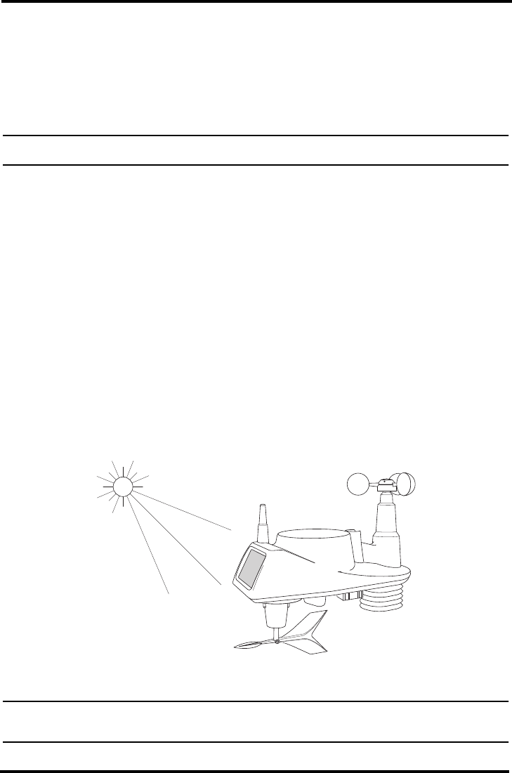
• In the northern hemisphere, the solar panel should face south for maximum sun
exposure.
• In the southern hemisphere, the solar panel should face north for maximum sun
exposure.
Note: If you install the ISS with the solar panel pointing in a direction other than south, you will need to use the
wind direction calibration function in the Vantage Vue Console in order to obtain accurate wind direction
readings.
Orienting the ISS Solar Panel for maximum exposure.
In the southern hemisphere the
Solar Panel should face north for
maximum exposure.
In the northern hemisphere
the Solar Panel should face
south for maximum exposure.
General ISS Installation Guidelines
11
Installation Instructions
The Vantage Vue ISS can only be mounted on the top of a pole or solid round bar that
is between 1.0 and 1.8 inches (25 - 46mm) in outside diameter.
Recommended Accessories for Pole Mounting
• Use the Mounting Tripod (#7716) for easy roof-mounting.
• Use the Mounting Pole Kit (#7717) to raise the installation height of the ISS by
up to 37.5" (0.95 m).
General Guidelines for Installing on a Pole
• With the supplied U-bolt, the ISS can be mounted on a pole having an outside
diameter ranging from 1" to 1.8" (25 – 46mm).
• To mount on a smaller pole, obtain a U-bolt that fits the base openings but that
has a longer threaded section. If mounting the ISS on a smaller pole with the
included U-bolt, the threaded sections of the U-bolt will be too short to securely
mount the ISS.
.
Installing the ISS on a Pole
1. If you are mounting your ISS on a Davis Mounting Tripod (product number 7716)
or the pole included with a Davis Mounting Pole Kit (product number 7717),
follow the instructions included with those Davis products for proper installation.
If you are not using one of these Davis products, mount any galvanized steel pole
having an outside diameter ranging from 1" to 1.8" (25 – 46mm), following the
guidelines explained in “General ISS Siting Guidelines” on page 9.
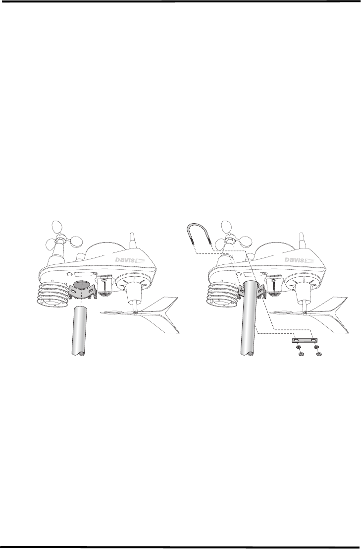
2. Using the illustration above as a guide, hold the ISS so that the Wind Cups and
Radiation Shields are on the left and gently place the ISS on top of the steel pole.
3. While holding the mounting base of the ISS against the pole, place the two ends of
the U-bolt around the pole and through the two holes in the C-shaped bracket on
the base.

Finishing the Installation
12
4. Slide the metal backing plate over the bolt ends as they stick out from the far side
of the bracket.
5. Secure the backing plate with a flat washer, lock washer, and hex nut on each of the
bolt ends, as shown in the illustration.
6. Tighten the hex nuts with your fingers only so that the ISS is just secure enough
on the pole for you to release your grip.
Note: Do not tighten the hex nuts with a wrench yet. Tighten the hex nuts enough to safely hold the ISS on the
mounting pole, but leave them loose enough to swivel the ISS base on the pole.
7. If you are in the northern hemisphere, rotate the ISS on the pole so that the solar
panel is facing south; if you are in the southern hemisphere, rotate the ISS so that
the solar panel is facing north. The more precisely the solar panels face due south
or north, the more accurate your wind direction readings will be.
Note: Do not rely on a compass unless it is properly calibrated. In North America there can be up to 15° varia-
tion between true north and a raw compass reading.
Finishing the Installation
The ISS is designed with the assumption that the solar panel faces due south. The
wind vane relies on this orientation to correctly assign wind direction. After the ISS
has been permanently mounted, you may need to correctly calibrate your console so
that you receive accurate wind direction readings from the ISS. Refer to your Vantage
Vue ConsoleManual to calibrate your console.
Note: This must be done if you are in the southern hemisphere, or if you are in the northern hemisphere, and for
some reason, cannot install in your ISS with the solar panel facing south.
Clearing Data Collected During Testing and Installation
Now that the ISS is mounted outside, any data that was collected and stored in the
console during testing and mounting can be cleared.
To clear all the collected data on the console:
1. Press WIND so that selection arrow appears adjacent to the wind data on the
display. Confirm that wind speed is displayed on the compass rose.
2. Press 2ND, then press and hold CLEAR for at least six seconds and until you see
“CLEARING NOW” in the weather center.
13
Maintenance and Troubleshooting
Maintenance
Cleaning the Radiation Shield
The outer plating of the radiation shield should be cleaned when there is excessive
dirt and build-up on the plates. Use a damp cloth to clean the outer edge of each ring.
Note: Spraying down or using water excessively to clean the radiation shield can damage the sensitive sensors
or alter the data the ISS is transmitting.
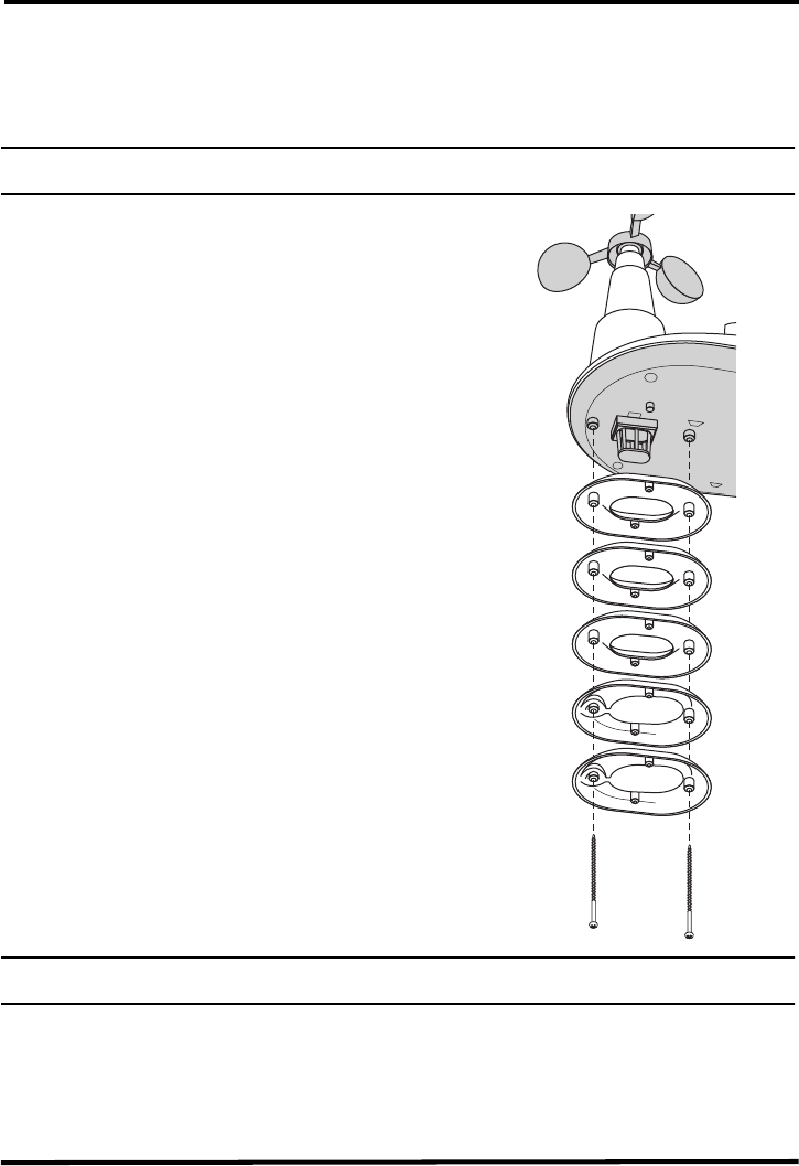
Check the radiation shield for debris or insect
nests at least once a year and clean when
necessary. A buildup of material inside the
shield reduces its effectiveness and may cause
inaccurate temperature and humidity readings.
To thoroughly clean the radiation shield:
1. Using a Phillips head screwdriver, loosen
the two 4'' screws holding the five radiation
shield plates together, as shown in the figure
at right.
2. Taking care to maintain the order in which
the five plates are assembled, separate the
plates as shown and remove all debris from
inside the shield.
3. Reassemble the plates in the same order in
which they were disassembled, and fasten
them together using a Phillips head screw-
driver to tighten the 4'' screws, as shown in
the illustration.
Cleaning the Rain Collector, Debris
Screen, and Tipping Spoon Module
To maintain accuracy, thoroughly clean the rain
collector cone and debris screen as needed or at
least once a year.
Note: Cleaning the rain collector and tipping spoon may cause false rain readings. See your Vantage Vue Con-
sole Manual for instructions on clearing weather data if you suspect this is occuring.
1. Use a damp, soft cloth to remove any debris from the Rain Collector and Debris
Screen.
2. Use pipe cleaners to clear any debris remaining in the screen.
3. When all parts are clean, rinse with clear water.
Maintenance
14
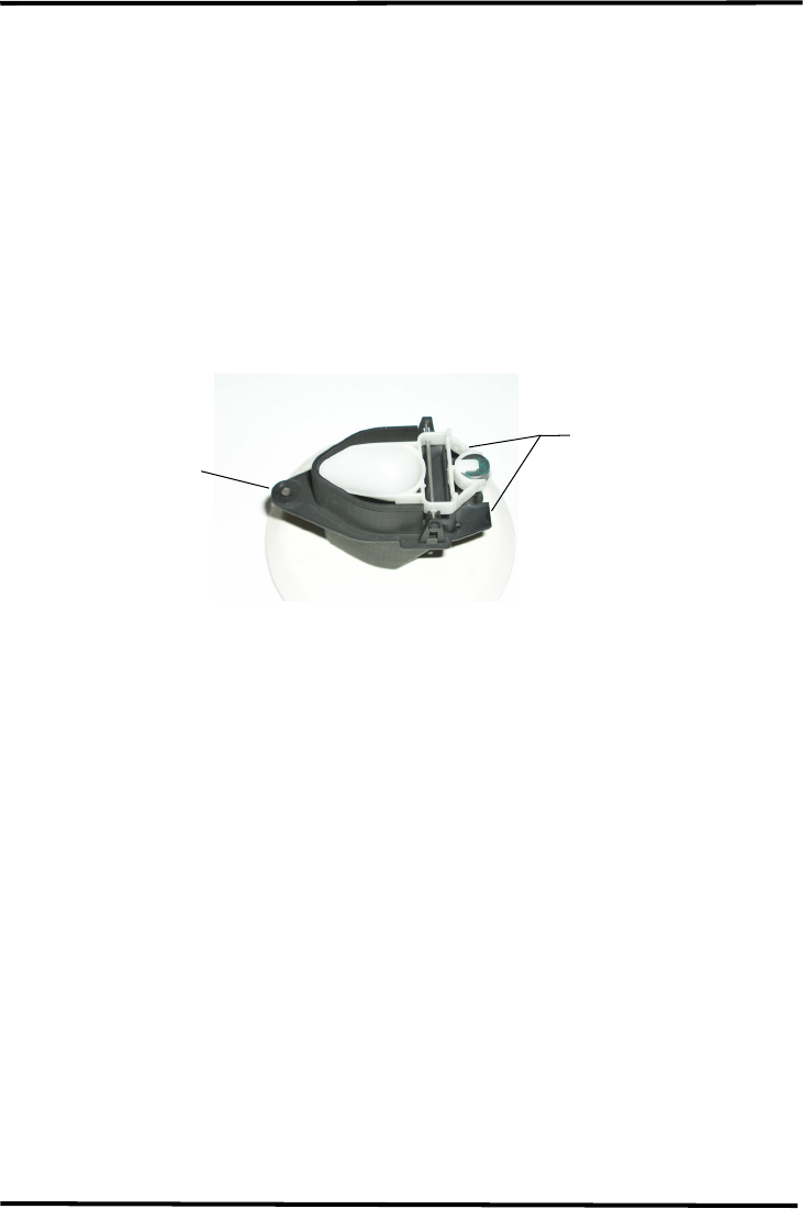
To clean the Tipping Spoon module, it must first be removed from the ISS base.
To remove this module from the base, follow these steps:
1. Unscrew the thumbsscrew securing the Tipping Spoon assembly to the ISS
base. This screw is on the “slightly pointed” side of the assembly and will be
on the “down” side of the ISS base when the ISS is held with the Wind Vane
on the right.
Note: Do not unscrew the hex-head screw on the opposite “flat” side of the module (see second drawing,
below).
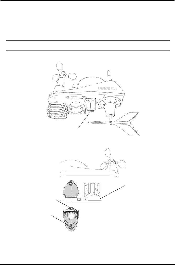
Tipping Spoon
Assembly
Unscrew this Phillips
head screw to remove
module from the ISS
View of Tipping Spoon module after removal from underside of ISS base.
Anemometer
Battery compartment
cover
Do not unscrew this hex-
head screw when remov-
ing module from the ISS.
Doing so will alter the
sensitive calibration of
this module.
Troubleshooting
15
2. Let the “pointed” side of the module drop away from the ISS base, and slide the
module down and away from the base, as shown above.
3. Use a damp, soft cloth to gently remove any debris from the Tipping Spoon mod-
ule, being careful not to damage any moving parts or scratch the spoon.
4. When all parts are clean, rinse with clear water, and replace the module into the
bottom of the ISS base as follows:
a) Tilting the module at a slight angle relative to the ISS base, insert the two tabs on
the “flat” side of the module (under the tipping magnet, as noted in the figure
below) into the “flat” side of the opening of the ISS base.
b) Rotate the “pointed” side of the module up to the base, and tighten the Phillips
head screw.
Troubleshooting
Troubleshooting ISS Reception
If the console isn’t displaying data from the ISS, perform the following steps:
1. Verify that the console is powered and is not in Setup Mode.
2. Make sure that the ISS battery is properly installed.
3. Walk around the room with the console, standing for a few moments in various
locations, to see if you are picking up signals from the ISS. Look on the screen’s
lower left quadrant for the small graphic of a radio antenna. Small “radio wave
semi-circles” display above the antenna and toggle on and off when the console
receives a transmission.
If you do not see the antenna’s radio wave graphic slowly blinking, regardless of
where you stand with the console, you should call the Davis Technical Support
Department. See “Contacting Davis Instruments” on page 17 for more informa-
tion.
4. If the Transmitter ID LED remains unlit, there is a problem with the ISS transmit-
ter. Call Technical Support. See “Contacting Davis Instruments” on page 17.
Replacing the Tipping Spoon module in the ISS base.
Insert the Phillips
head screw here.
When replacing this
module, first slide these
tabs into the ISS base,
then insert the Phillips
head screw.

Troubleshooting
16
5. If the Transmitter IDLED flashes repeatedly but your console isn’t picking up a sig-
nal anywhere in the room, it could be related to one of the following causes:
• You changed the ISS Transmitter ID at the ISS or console, but not at both.
• Reception is being disrupted by frequency interference from outside sources, or
the distance and barriers are too great.
Interference has to be strong to prevent the console from receiving a signal
while in the same room as the ISS.
• There is a problem with the Vantage Vue console.
6. If a problem with receiving the wireless transmission still exists, please contact
Technical Support. See “Contacting Davis Instruments” on page 17.
When to Change the ISS Transmitter ID
The Vantage Vue ISS transmits weather information to the Vantage Vue Console
using one of eight selectable Transmitter IDs.
Note: The transmitter on the ISS and receiver on the console will communicate with each other only when both
are set to the same ID.
The default Transmitter ID for both the ISS and the Vantage Vue console is 1, and
should work fine for most situations. Change the Transmitter ID if any of the
following issues are true:
• Another Davis Instruments wireless weather station operating nearby already
uses Transmitter ID 1.
• An additional wireless transmitting station has been purchased for use with the
Vantage Vue and it has been designated as Station No. 1 instead of the selected
ISS.
On the ISS, the Transmitter ID is set using the Transmitter ID Pushbutton located
on the underside of the ISS base. To see a drawing showing this button’s location
and a procedure for changing the ISS transmitter ID, refer to “Set a New Transmit-
ter ID on the ISS” on page 7.
Set the Vantage Vue console to the same ID as the transmitters, as described in the
Vantage Vue Console Manual.
Using Two Transmitting Stations
A single Vantage Vue console can recieve signals from one ISS, either a Vantage Vue
or a Vantage Pro2 ISS, and an optional anemometer transmitter kit. See your Vantage
Vue Console Manual for information on configuring Transmitter IDs.
If a Sensor Functions Intermittently
Carefully check all connections from the sensor to the ISS. .
If the sensor still functions intermittently contact Technical Support.
Most Common Rain Collector Problem
If the rain collector seems to be under-reporting rainfall, clean the debris screen and
tipping spoon module to clear out any debris.

Troubleshooting
17
Most Common Anemometer Problems
“The wind cups are spinning but my console displays 0 mph.”
The signal from the wind cups may not be making it back to the display.
Remove the cups from the anemometer (loosen the set screw). Put the cups back
onto the shaft and make sure to slide them down the shaft as far as possible.
“The wind cups don’t spin or don’t spin as fast as they should.”
The anemometer may be located where wind is blocked by something, or there
may be friction interfering with the cups’ rotation. Remove the wind cups
(loosen the set screw) and clear out any bugs or debris which may be interfering
with the cup rotation. Turn the shaft the cups rotate on. If it feels gritty or stiff,
contact Davis Technical Support.
Note: Do not lubricate the shaft or bearings in any way. When replacing the cups, make sure they are not rub-
bing against any part of the anemometer head.
“Readings aren’t what I expected them to be.”
Comparing data from your ISS to measurements from TV, radio, newspapers, or
a neighbor is NOT a valid method of verifying your readings. Readings can vary
considerably over short distances. How you site the ISS and anemometer can
also make a big difference. If you have questions, contact Davis Technical
Support.
Contacting Davis Instruments
If you have questions about the ISS or Vantage Pro2 system, or encounter problems
installing or operating the weather station, please contact Davis Technical Support.
Note: Please do not return items to the factory for repair without prior authorization.
(510) 732-7814 – Technical Support phone, Monday – Friday, 7:00 a.m. – 5:30 p.m.
Pacific Time.
(510) 670-0589 – Technical Support Fax.
support@davisnet.com – E-mail to Technical Support.
info@davisnet.com – General e-mail.
www.davisnet.com – Download manuals and specifications from the Support section.
Watch for FAQs and other updates. Subscribe to the e-newsletter.