Davis Instruments DWW6800 EnviroMonitor Wireless Weather Station User Manual
Davis Instruments EnviroMonitor Wireless Weather Station
UserManual.wiki
>
Davis Instruments
>
DWW6800 User Manual
Users Manual
Navigation menu
Upload a User Manual
Namespaces
Wiki Guide
HTML
PDF
Info
Views
User Manual
Discussion / Help
Navigation

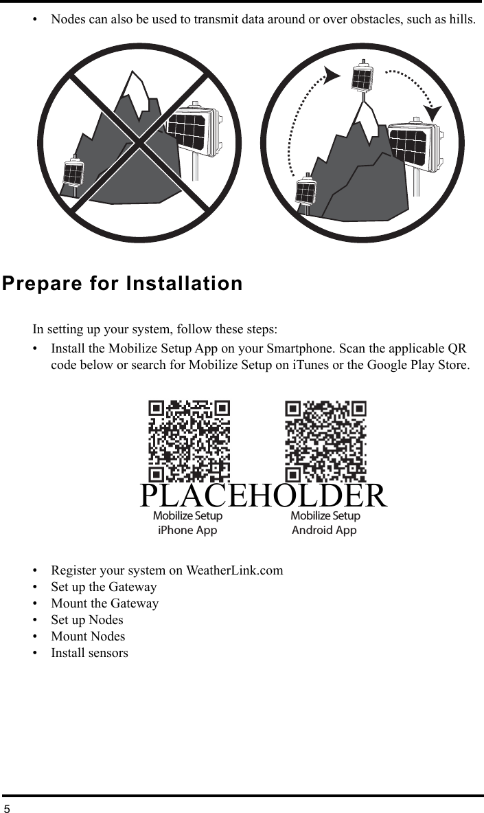
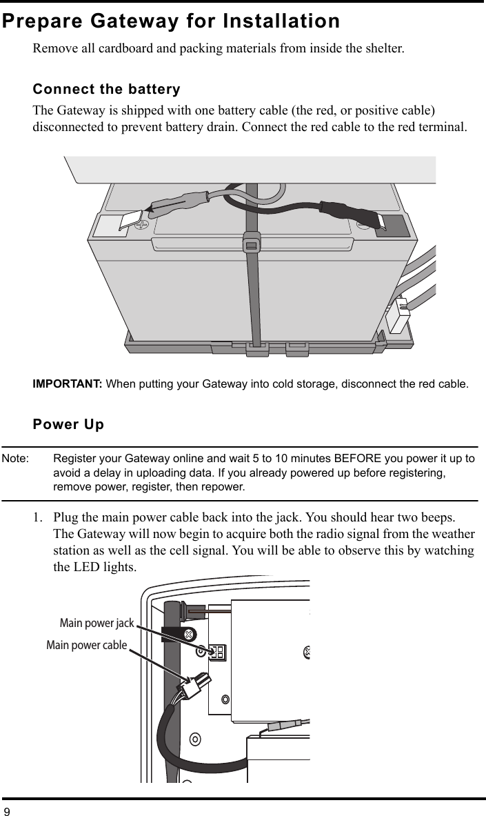
![8• For accurate barometric pressure data, enter the elevation at which your Vantage Connect will be mounted. Fine tune this sensor by entering the local barometric pressure reading. (Sources of this information include your local airport or radio station)• Select your anemometer and rain collector types. • For accurate year-to-date rain data, enter the year-to-date rainfall as of today, and when your rain season starts.• Station Alarms (Optional): Set alarms for high and low weather conditions. Vantage Connect will send up to 20 (counting both activate and deactivate) email or text alarm notifications per day, outside of the plan’s intervals, when these conditions exist. • If necessary, you may calibrate temperature, humidity, and wind readings. (Be careful when deciding to calibrate; Davis weather stations are factory-calibrated for accuracy and may not match less accurate or less local data such as reported on television or a web page.) Enter the amount of offset you want the temperature or humidity reading to be reported. For example, if you believe your outside temperature data is consistently 2 degrees too low, enter +2. If you believe the outside humidity data is consistently 5% too high, enter -5. You must calibrate the wind direction if your anemometer cannot be mounted so that the arm points true north. Enter the direction the arm points, if not zero, in degrees from 1° to 359°.• Click Save.3. My Account. Enter your account information.• Enter your City, State, Country, and latitude & longitude• Enter a name for your station (this will become your web page title)• Choose a station type and usage from the pull-down menus• Choose whether to show display 24-hour time • Check the “Keep ‘My Weather’ private” box if you do not want your current weather to be seen without a password. (No private information appears on this screen.)4. If any erroneous data has been logged during setup and installation, you should clear highs and lows. (For example, while setting up, the wind cups and vane were spun. This false “high wind” data should be cleared.) To clear, click Manage Stored Data.5. Click Save.6. You can edit these settings at any time by logging in to your account and clicking My Account then [edit] (to edit account information or change your password); or, in the My Device box: Edit Configuration, Edit Settings, or Manage Stored Data.Note: These settings and configurations will be pushed to the Vantage Connect at the first update after it is set up and powered. The changes will then be sent to your WeatherLink.com page at the next update. So the changes will not appear on your page after at least 2 update intervals. (Update intervals are 5, 15 or 60 minutes depending on your service plan). With high network traffic, this may take longer.](https://usermanual.wiki/Davis-Instruments/DWW6800/User-Guide-2873202-Page-10.png)