Davis Instruments DWW6810 EnviroMonitor Node User Manual
Davis Instruments EnviroMonitor Node
Users Manual
Product number 6810
EnviroMonitor
Sensor Node
USER
MANUAL
Davis Instruments, 3465 Diablo Avenue, Hayward, CA 94545-2778 U.S.A. • 510-732-9229 • www.davisnet.com
R
™
R
®®
®
®

0
This device complies with part 15 of the FCC Rules. Operation is subject to the following two
conditions: (1) This device may not cause harmful interference, and (2) this device must accept any
interference received, including interference that may cause undesired operation.
The antenna(s) used for this transmitter must be installed to provide a separation distance of at least
20 cm from all persons and must not be co-located or operating in conjunction with any other antenna
or transmitter.
Changes or modification not expressly approved in writing by Davis Instruments may void the
warranty and void the user's authority to operate this equipment.
FCC ID: IR2DWW6810
IC: 3788A-6810
This device complies with Industry Canada license-exempt RSS standard(s). Operation is subject to
the following two conditions: (1) this device may not cause interference, and (2) this device must
accept any interference, including interference that may cause undesired operation of the device.
Le présent appareil est conforme aux CNR d'Industrie Canada applicables aux appareils radio
exempts de licence. L'exploitation est autorisée aux deux conditions suivantes : (1) l'appareil ne doit
pas produire de brouillage, et (2) l'appareil doit accepter tout brouillage radioélectrique subi, même si
le brouillage est susceptible d'en compromettre le fonctionnement.
This product complies with the essential protection requirements of the EC EMC Directive 2004/108/
EC; Low Voltage Directive 2006/95/EC; FCC Part 15.247 902-928 Mhz; and FCC Part 15.247 sub-
part C DTS 2400-2483.5 MHz. Complies with Canadian Standard IC RSS 247 Issue 1 902 -928 MHz
and RSS-Gen Issue 4 FHSS. Complies with EN 300 220-2 V2.4.1; EN 300 328 V1.9.1; EN 300 328-
3 V1.6.1; EN 301 489-3, EN 301 489-17 V2.2.1; EN 61000-4-2 (2009) FSD; EN 61000-4-3 (2006)
Radiated Immunity; EN 61000-4-4 (2004) EFTB; and EN 61000-4-6 (2009) Conducted Immunity.
EC-Declaration of Conformity
Directive 1999/5/EC (R&TTE Directive)
Manufacturer / responsible person: Davis Instruments
Perry Dillon, Compliance Engineer
Address: 3465 Diablo Ave., Hayward, CA 94545 USA
Declares that the product:
6810 and 68XX
Complies with the essential requirements of
Article 3 of the R&TTE 1999/5/EC Directive, if used for its intended use and that the following standards have
been applied:
1. Health (Article 3.1.a of the R&TTE Directive)
Applied standard(s)(EC recommendation 1999/519/EC)
2. Safety (Article 3.1.a of the R&TTE Directive)
Applied standard(s)(EN 60950-1:2006/A11:2009/A1:2010/A12:2011)
3. Electromagnetic compatibility (Article 3.1.b of the R&TTE Directive)
Applied standard(s)EN301489-1, V1.8.1, EN301489-7, V1.3.1,
4. Efficient use of the radio frequency spectrum (Article 3.2 of the R&TTE Directive)
Applied standard(s)EN301511, V9.0.2
The technical documentation relevant to the above equipment will be held at:
Davis Instruments at 3465 Diablo Ave, Hayward CA 94545
1
Welcome to EnviroMonitor Sensor Node
An EnviroMonitor System includes a Gateway and a number of Nodes that house up
to four sensors each. The Nodes transmit the sensor data to the Gateway, either
directly from Node to Gateway, or indirectly by “hopping” from Node to Node to
Gateway via mesh network operating at 900 MHz (different in the EU). The
Gateway then sends the data via cellular connection to the Cloud.
EnviroMonitor can be customized for any size installation. Each Gateway can
receive from as many as 50 Nodes. Additional Gateways can be added to your
system to receive from another set of Nodes.
Before installing sensors and sensor nodes, should first set up and activate your
EnviroMonitor Gateway.
You should have already downloaded the EnviroMonitor Mobilize Setup app on the
smartphone you will use while setting up the nodes. Install the Mobilize Setup App
on your Smartphone. Scan the applicable QR code below or search for Mobilize
Setup on iTunes or the Google Play Store.
Note: Cellular connection is not required for set up of the nodes. If cellular connection is not
reliable where the Nodes will be installed, make sure to open the app before going out
to the site while still connected to the internet. This will ensure your app has the latest
information.
Mobilize Setup
iPhone App
Mobilize Setup
Android App
PLACEHOLDER
2
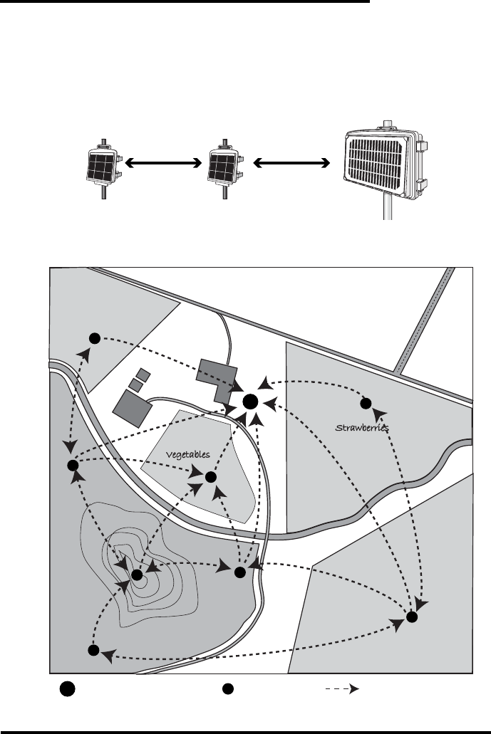
Plan Installation of Nodes
Before installation, plan your system. After determining which sensors you want and
where you want to install them, make sure you have the correct number of Nodes to
support those sensors. The maximum distance between Nodes and Gateway will be
different for installation depending on many factors, but in ideal conditions may be
up to 2,000 feet (600 meters).
Make a sketch of your installation to get an idea of where the Gateway and Nodes
should go.
™
≤2000 ft
≤600 m
≤2000 ft
≤600 m
SAMPLE FARM
Vegetables
Apples
Grapes
Artichokes
Hwy. 10
Davis Rd.
Strawberries
G
G
N
N
N
N
N
N
N
N
N
Diablo Creek
Gateway Node Transmission Mesh
3
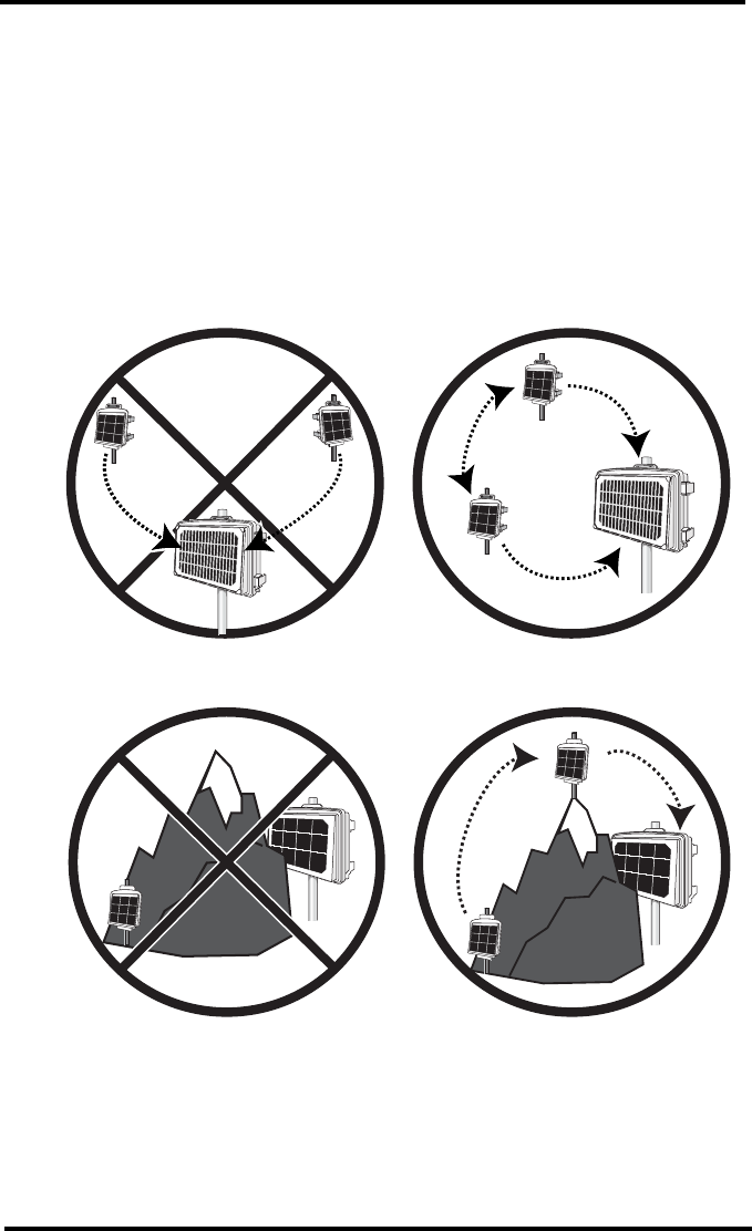
Siting the Nodes
• Make sure each Node is sited so that it has at least two ways to reach the
Gateway. It should be within transmission distance (up to 2,000 feet/600
meters) of either two other Nodes, or the Gateway and another Node. This
allows the mesh to “heal” any temporarily impaired transmission paths and will
ensure data reaches the Gateway. You can have any number of hops from Node
to Node. A Node can even be installed simply to transmit data from more
distance Nodes to the Gateway, without any sensors installed in it. By planning
the system’s “transmission mesh,” data can be relayed in from the most remote
corner of your installation.
• Nodes can also be used to transmit data around or over obstacles, such as hills.
™
™
™
™
4
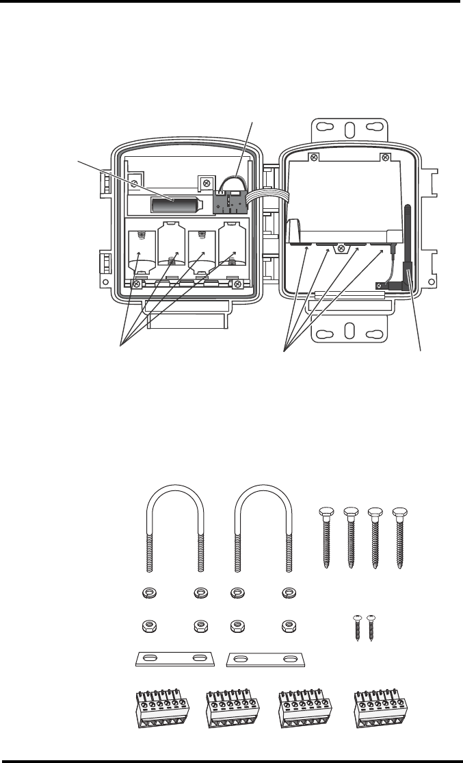
Installing the Nodes and Sensors
Contents of Node package
Hardware Kit
D-Cell Battery
Compartments
(batteries not included)
Rechargable
Lithium
Battery
(included)
Solar Panel Cable
Sensor
Junctions
Antenna
1/4" Lock Washers
1/4" Hex Nuts
U-Bolts
Backing Plates
6-Wire Sensor
Connectors
1/4" x 1 1/4" Lag Screws
#6 x 3/8 Screws
(not needed)

5
Requirements & Tools for Installation of
Nodes and Sensors
• Node with at least one sensor
• Small flathead screwdriver
• 4 D-cell batteries
• Smartphone with Setup app installed
• Wire cutter/stripper
• Mounting pole or post
• Wrench
• Screwdriver if mounting to a post
Note: You should install Nodes from closest to Gateway to furthest from Gateway so that
each Node can establish a connection with the Gateway or a Node that has already
been installed.
Prepare Node for Installation
Plug in the solar panel cable. Install 4 D-cell batteries making sure they are
installed according to the + and - marks in the battery compartment.
The Node will power up. LEDs will indicate connection.
Connect Node to Gateway
1. Take the Node and smartphone to the general location in which you wish to
install your Node.
2. Make sure the phone’s Bluetooth is on.
3. Open the app on the smartphone. Tap “Add a Node.”
4. Bring the phone close to the Node or gently tap the phone to the node.
5. Follow the prompts in the app as it finds the Node and connects it to the
Gateway. This transmits the Gateway’s identifying information to the Node
and allows its data to be received by the Gateway. Having specific
identification for each Gateway/Node pair allows you to have multiple
Gateways without cross transmission. Once the Gateway identification is
transmitted to the Node, it will communicate only with that Gateway.
You will hear two beeps to indicate that the Gateway’s identifying information
has been transferred to Node. Using the app, you will be see this Node’s serial
number appear on the list for proper Gateway.
You will know that the connection between the Node and Gateway is complete
when you see green light. If they cannot “find” each other, try moving the
Node to a different location. If the location of the Node can not be changed,
consider installing a different Node closer to the Gateway, to act as a repeater.
It does not have to have any sensors installed.
Install the Sensor(s)
Each note has four sensor junctions. You can install up to four sensors in these
junctions.You can install the sensors before or after mounting the node shelter. For
6
example, if you plan to mount the node on a tower, you will want to install the
sensor first.
1. Install the sensor in the into the sensing medium per the manufacturer’s
instructions and the needs of the environment, making sure the sensor is
installed within cable reach of the Node.
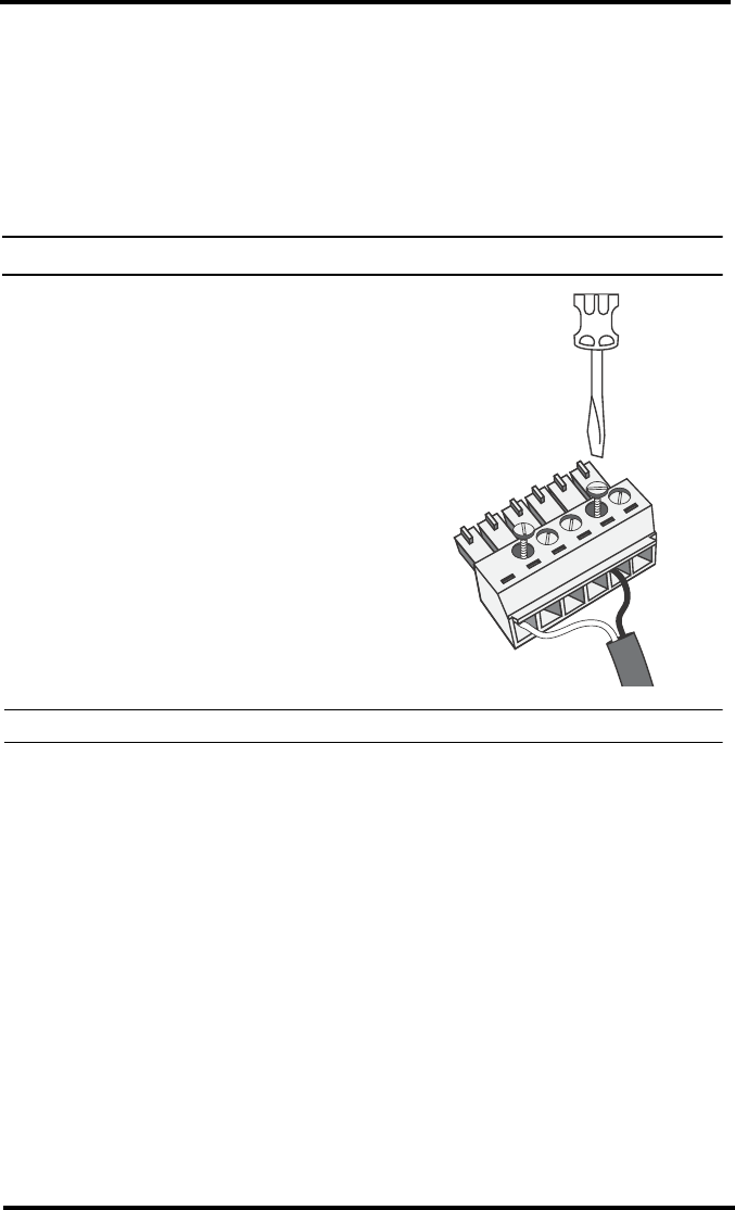
2. Wire the sensor into one of the 6-wire sensor connectors. Each sensor has
specific wiring specifications. In the app, find the sensor on the Sensor
Junction Wiring Diagram to determine how it should be wired to the junction.
Note: If the sensor has a RJ-jack on its cable, remove it and strip the wires.
3. Using a small flathead screwdriver,
loosen the appropriate screws and insert
the bare wires.
CAUTION: Do not let bare wires touch each other.
4. Tighten the screws.
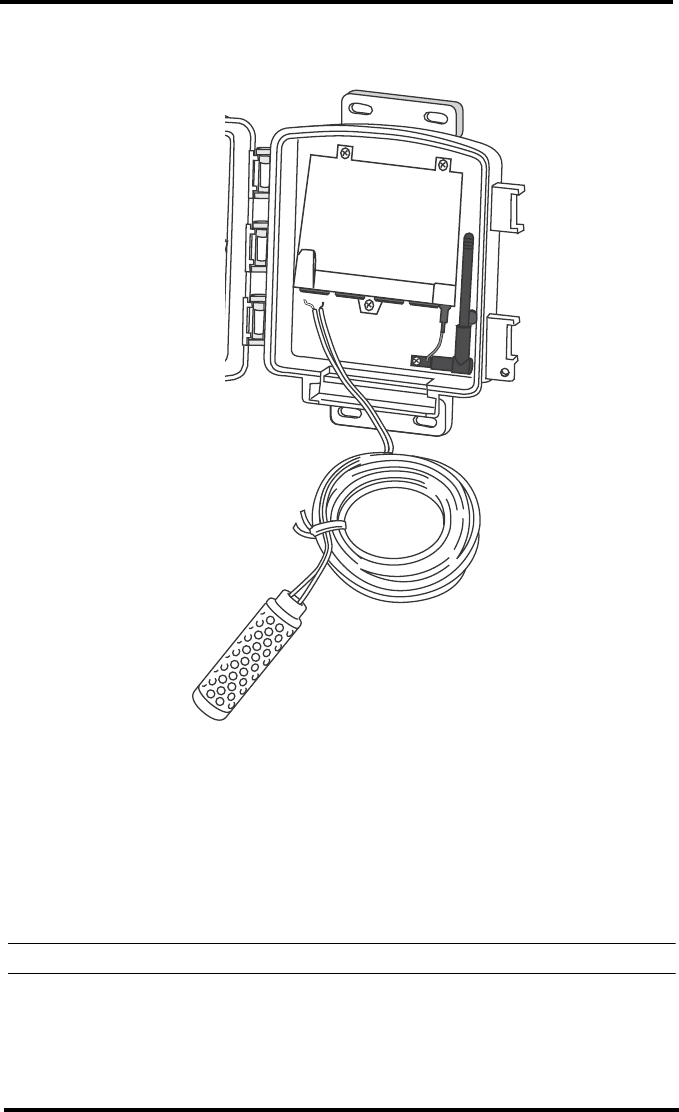
5. Plug the sensor junction into the sensor port indicated by the app.
6. Run the sensor cable down and out of the box through the bottom. Make sure
it will be enclosed by the foam when the shelter door is closed.
1
5
7
7. When all sensors are installed, close the shelter door, making sure all cables
are against the foam and not the hard plastic of the door.
Mount the Node Shelter
The Node shelter can be mounted on a pole or a flat surface such as a wall or a
wooden post.
It is important that the shelter be mounted so that the solar panel gets the greatest
amount of sunshine -- the solar shelter should be facing south (in the northern
hemisphere) or north (in the southern hemisphere).
Tip: Mounting the shelter may be easier if done by two people.
8
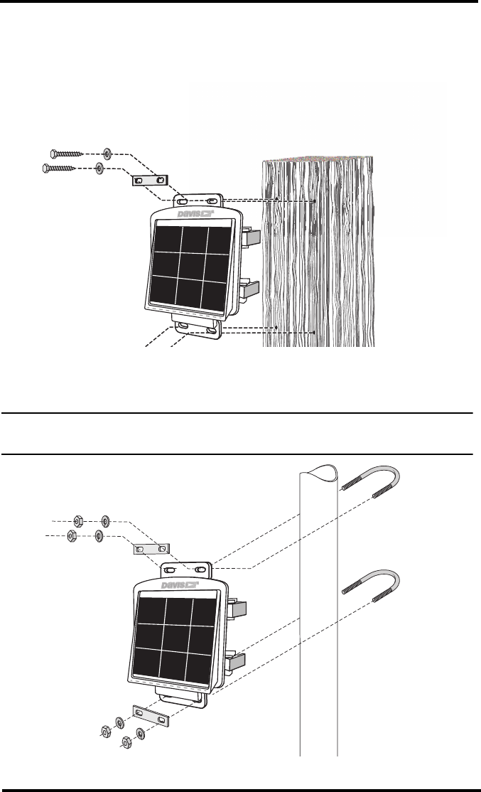
Mounting on a Flat Surface
Attach the shelter to the mounting surface in the desired location using the lag
screws and backing plates as shown below. Use a pencil or a center-punch to mark
the location of the pilot hole.
Mounting On a Pole
Mount the Gateway onto a pole with an outside diameter of 0.84'' to 1.84'' (21 mm
to 27 mm) using the U-bolts, backing plates, washers, and hex nuts provided.
Note: For mounting on larger diameter pipes, the housing can accommodate U-bolts with
5/6'' (8 mm) threads for pipes up to 2.40'' (61 mm) outside diameter (not provided).
®®
®
9
Troubleshooting
How can I tell if my battery voltage is getting too low?
Our server will monitor your battery voltage and will trigger an e-mail warning if
it should get critically low (approximately 14 days of power). The e-mail will go to
both the registered customer’s e-mail address as well as the alarm e-mail address
(if one has been set up).
My installation is in a low light area. Can I add another solar panel?
Yes. You can add an Extra Solar Panel Kit (product number 6616).
My status LEDs are not blinking.
Ma
No data is being uploaded.
Try these steps:
• Mak
What do the LED lights indicate?
If there is an error in getting a signal, the status LEDs will flash to indicate the type
of error.
Refer to the table (appropriate for your model) below to ascertain what the LEDs
mean so that you can report the problem to Technical Support.
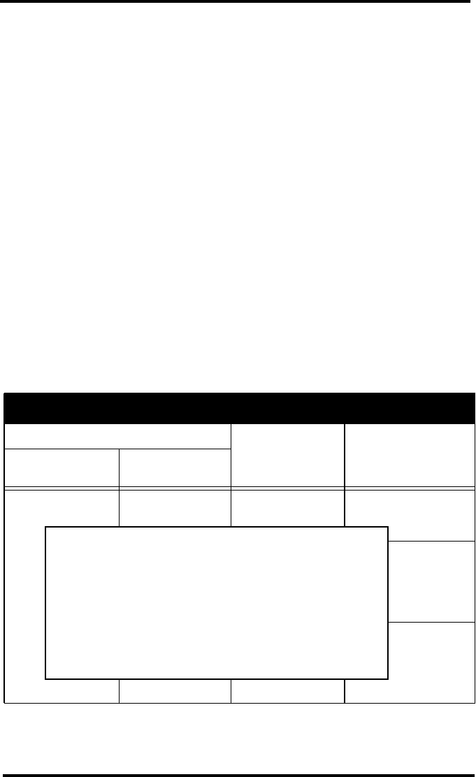
Node Error Messages
LED Behavior
Indicates What to do
Lower LED
(Network)
Upper LED
(Wx Status)
Rapidly flashes
blue on and off,
while upper red
LED blinks to
indicate the error
code. Pauses and
repeats.
Blinks red once,
pauses and
repeats.
No cellular signal
found.
Move the Vantage
Connect to a different
location.
Blinks red twice,
pauses and
repeats.
Low cellular signal
strength.
Vantage Connect may
function in this
location, but you may
want to move if
possible.
Blinks red a
specific number
(3 to 10) of times
There is a cell
error. The number
of red flashes
indicates the error
code number.
Contact Tech Support
and report the error
code.
PLACEHOLDER

Enviromonitor® Node
Product Numbers 6810, 68XX Document Number: 07395.339 Rev. A January 12, 2016
Enviromonitor®, Vantage Pro®, Vantage Pro2™, Vantage Vue® , and WeatherLink® are trademarks of
Davis Instruments Corp., Hayward, CA.
© Davis Instruments Corp. 2015. All rights reserved.
Information in this document subject to change without notice. Davis Instruments Quality Management
System is ISO 9001 certified.
3465 Diablo Avenue, Hayward, CA 94545-2778 U.S.A.
510-732-9229 • Fax: 510-732-9188
E-mail: info@davisnet.com • www.davisnet.com
®
Contacting Davis Technical Support
For questions about installing or operating your EnviroMonitor Node,
please contact Davis Technical Support. We’ll be glad to help.
Specifications
General:
Operating Temperature. . . . . . . . . . . . . . . . -40° to +140°F (-40° to +60°C)
Charging Temperature . . . . . . . . . . . . . . . . -4° to +120°F (-20° to +49°C)
Storage Temperature . . . . . . . . . . . . . . . . -40° to +140°F (-40° to +60°C)
Current Draw . . . . . . . . . . . . . . . . . . . . . . . 25mA typical, 1A peak
GPRS class 10: 146mA typical
Transmitter Power . . . . . . . . . . . . . . . . . . . 2W @ 850/900 MHz (Class 4)
1W @ 1800/1900 MHZ (Class 1)
Housing Material . . . . . . . . . . . . . . . . . . . . Rugged ASA Plastic
Dimensions (width x length x height) . . . . . 13.75 X 10 X 4.15 inches
(34.9 X 25.4 X 10.5 cm)
Weight . . . . . . . . . . . . . . . . . . . . . . . . . . . . 8.14 lbs. (3.69 kg)
Batteries. . . . . . . . . . . . . . . . . . . . . . . . . . . . . . XXX
Dimensions without tabs . . . . . . . . . . . . . . 5.95” L x 3.70” H x 2.00” D;
151 mm L x 98 mm H x 51 mm D
Certifications: . . . . . . . . . . . . . . . . . . . . . . . . . FCC PTCRB CE Carrier
Online www.davisnet.com
See the Weather Support section for copies of user
manuals, product specifications, application notes,
software updates, and more.
E-mail support@davisnet.com
Telephone (510) 732-7814
Monday - Friday, 7:00 a.m. - 5:30 p.m. Pacific Time.
PLACEHOLDER