Davis Instruments DWW765Y Vantage Pro 2 Wireless Repeater User Manual 2
Davis Instruments Vantage Pro 2 Wireless Repeater Users Manual 2
Contents
- 1. Users Manual 1
- 2. Users Manual 2
Users Manual 2
Wireless Repeater
Installation Manual
For AC-Powered and Solar-Powered Repeaters
Models 7626 and 7627

Vantage Pro2™ Wireless Repeater Manual
Rev. A, June 2, 2005
Document Part Number: 07395.238
For Vantage Pro2 Wireless Repeaters: 7626, 7627
Vantage Pro® and Vantage Pro2™ are trademarks of Davis Instruments Corp., Hayward, CA.
© Davis Instruments Corp. 2005. All rights reserved.
Information in this document subject to change without notice.
3465 Diablo Avenue, Hayward, CA 94545-2778
510-732-9229 • Fax: 510-732-9188
E-mail: info@davisnet.com • www.davisnet.com
FCC Part 15 Class B Registration Warning
This equipment has been tested and found to comply with the limits for a Class B digital device, pursuant to Part 15 of the FCC
Rules. These limits are designed to provide reasonable protection against harmful interference in a residential installation. This
equipment generates, uses, and can radiate radio frequency energy and, if not installed and used in accordance with the
instructions, may cause harmful interference to radio communications.
However, there is no guarantee that interference will not occur in a particular installation. If this equipment does cause harmful
interference to radio or television reception, which can be determined by turning the equipment on and off, the user is encour-
aged to try to correct the interference by one or more of the following measures:
• Reorient or relocate the receiving antenna.
• Increase the separation between the equipment and receiver.
• Connect the equipment into an outlet on a circuit different from that to which the receiver is connected.
• Consult the dealer or an experienced radio/TV technician for help.
Changes or modification not expressly approved in writing by Davis Instruments may void the warranty and void the user's
authority to operate this equipment.
FCC ID: IR2DWW765Y
IC: 3788A-765Y
EC EMC Compliance
This product complies with the essential protection requirements of the EC EMC Directive 89/336/EC, as tested to the follow-
ing directives:
• ETSI EN 300 220
• ETSI EN 301 489
Transmitter and Repeater ID Worksheet
Circle all the transmitter and repeater IDs used in your network:
Transmitter Type Transmitter ID Repeater ID
1A
2B
3C
4D
5E
6F
7G
8H

i
Table of Contents
Introduction ......................................................................................................... 1
Included Components and Hardware.............................................................. 1
Wireless Repeater Installation Overview........................................................ 2
Applying Battery Power.................................................................................. 2
Repeater Configuration/Architecture .................................................................. 4
Repeater Architecture ..................................................................................... 4
Single Repeater Configuration........................................................................ 4
Advanced Repeater Configurations ................................................................ 5
Single Repeater Installation................................................................................. 8
Verify Transmitter ID ..................................................................................... 8
Verifying Communication with a Transmitter................................................ 9
Choosing a Location ..................................................................................... 11
Testing a Proposed Location......................................................................... 12
Advanced Repeater Installation......................................................................... 13
Multiple Repeater (Daisy-Chain) Installation............................................... 13
Multiple Transmitters, One Repeater Installation......................................... 15
Combination Network Installation................................................................ 17
Choosing Locations....................................................................................... 19
Testing Proposed Locations.......................................................................... 19
Mounting the Wireless Repeater....................................................................... 20
General Installation Guidelines..................................................................... 20
Installing the Repeater on a Flat Surface ...................................................... 20
Installing the Repeater on a Pole................................................................... 21
WeatherLink and Console Configuration.......................................................... 22
Repeater Information on the Console ........................................................... 22
Repeater Functionality in WeatherLink........................................................ 23
Maintenance and Troubleshooting .................................................................... 25
Communication Troubleshooting ................................................................. 25
Repeater Troubleshooting Error Codes......................................................... 25
Repeater Maintenance................................................................................... 27
Appendix A ....................................................................................................... 28
Specifications................................................................................................ 28
Repeater Board Display and Contents .......................................................... 29
1
Introduction
The Vantage Pro2™ Wireless Repeater can be used with any Vantage Pro2 wireless trans-
mitter station and re-transmits the information to a Vantage Pro2 compatible receiver
(Vantage Pro2 console or Envoy®).
Note: Not all consoles have the capability to access wireless repeater information. If your console or
Envoy has firmware older than May 2005, it does not have the capability to see and configure Van-
tage Pro2 wireless repeaters. To check your console’s firmware, press the DONE and up arrow (+)
keys. The firmware revision displays in the ticker tape section of the console. To check your Envoy’s
firmware in WeatherLink, Select Console Diagnostics from the Reports Menu and view the firmware
date displayed. If the console or Envoy firmware version is older than May 2005, a Vantage Pro2
updater can be used to update the console or Envoy. Contact Technical Support about acquiring an
updater for your console or Envoy.
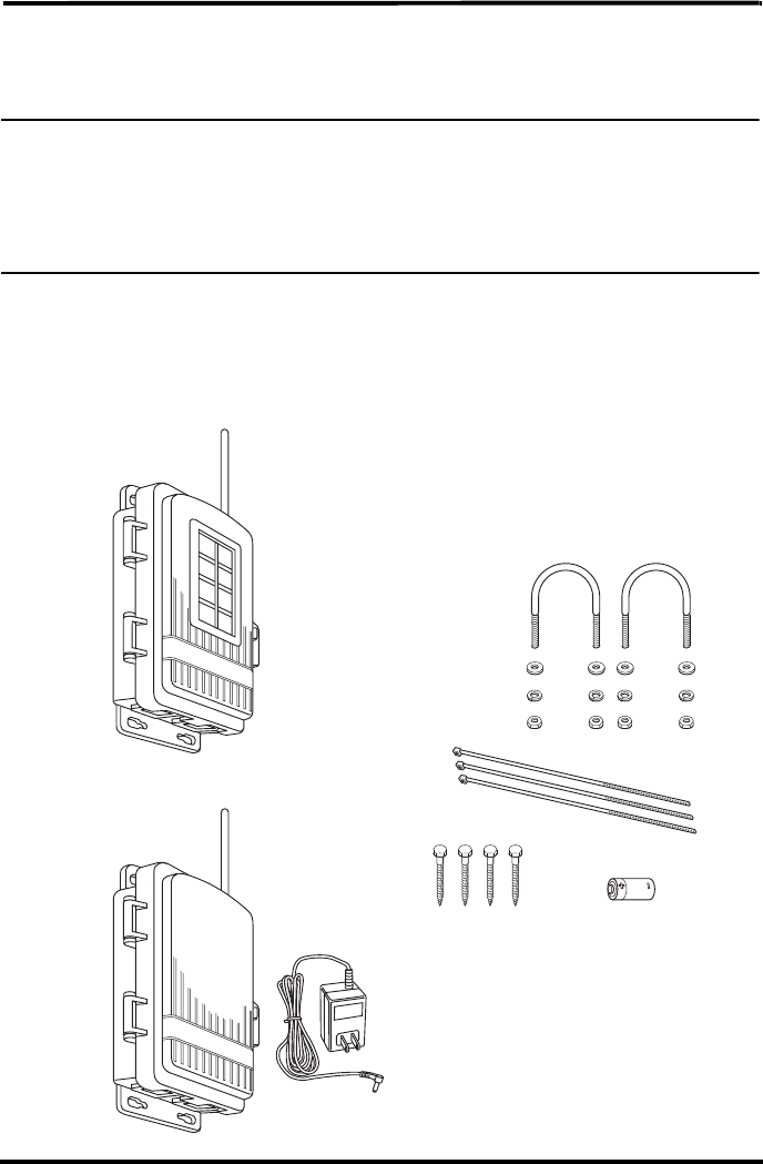
Included Components and Hardware
The Wireless Repeater comes with all the components and hardware shown in the follow-
ing illustration. Some of the hardware may not be used, depending on how the repeater is
installed.
Solar-powered
Shelter
3-Volt Lithium
Battery
8" Cable Ties
1/4" x 1-1/2"
Lag Screws
U-Bolts
1/4" Flat Washers
1/4" Lock Washers
1/4" Hex Nuts
110 Volt AC
Power Adapter
Shelter for
AC-powered unit
- OR -
AND
2
Tools for Setup
The following are tools and materials required to set up and install the wireless repeater:
• Ratchet with 4'' or longer extension, 7/16'' (11 mm) size socket
• Unbent paperclip
Wireless Repeater Installation Overview
The following is a brief overview of the steps involved for installing a repeater or series
of repeaters as part of your Vantage Pro2 wireless network:
• Apply power (battery or AC power).
• Determine the repeater/station configuration best suited to your wireless network.
• Verify communication with a transmitter or transmitters.
• Choose a location or locations for repeater(s).
• Test proposed location for communication strength.
• Configure the console or Envoy, and WeatherLink software for repeater information.
Applying Power
Applying Battery Power
1. Open the shelter enclosing the wireless
repeater to view the wireless repeater board.
2. Insert the 3-volt lithium battery into the bat-
tery socket at the top of the board. Be sure to
match the “+” sign on the battery with “+”
sign displayed in the battery socket.
Once the battery is installed, the wireless
repeater begins powering the board. Once
the repeater has sufficient power, the
repeater performs the Power-On Self Test
(POST) using the two LEDs located at the
bottom of the board. The STAT (status) LED
blinks red, yellow and then green, followed
by the TX LED blinking green once,
indicating that the repeater is powered up
and has passed POST.
Note: On battery power alone, it can take up to two to three minutes for the board to charge before the
repeater begins POST and the LED lights blink their pattern. With sufficient solar power or with the
AC adapter, the repeater powers up and is ready to communicate immediately.
Once the POST signal displays, the repeater is ready to communicate. If the repeater has
not displayed the POST light pattern within three minutes, see “Maintenance and Trou-
bleshooting” on page 25 for more information.
3-Volt Lithium
Battery
3
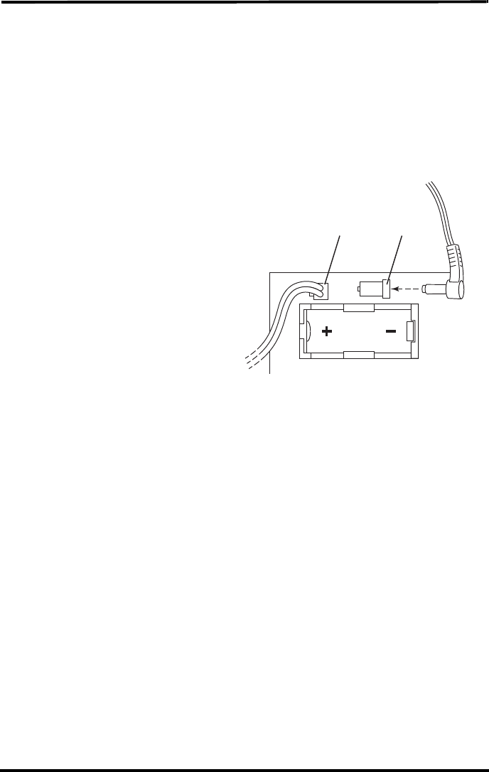
Applying AC Power (# 7626 AC-Power units)
1. Open the shelter enclosing the AC-powered wireless repeater to display the wireless
repeater board.
2. Thread the power adapter plug through the square black grommet into the transmitter
shelter.
Every Davis shelter has two of these grommets at the bottom of the shelter to provide
weather resistant entrances for cables. Remove the grommet, thread the power adapter
plug through it and replace the grommet in shelter if it is too hard to thread the power
adapter cable through the grommet in its current position.
3. Insert the power adapter plug into
the repeater power jack at the top of
the board above the battery socket.
Once the AC adapter is installed,
the wireless repeater begins power-
ing the board. The repeater imme-
diately performs the Power-On Self
Test (POST) using the two LEDs
located at the bottom of the board.
The STAT (status) LED blinks red,
yellow and then green, followed by
the TX LED blinking green once,
indicating that the repeater is pow-
ered up and has passed POST.
4. Once the POST signal displays, the repeater is ready to communicate. If the repeater
has not displayed the POST light pattern, unplug the AC adapter and re-apply AC
power. If the repeater has still not performed POST and displayed the light pattern, see
“Maintenance and Troubleshooting” on page 25 for more information.
6RODU3RZHU7DE $&$GDSWHU

4
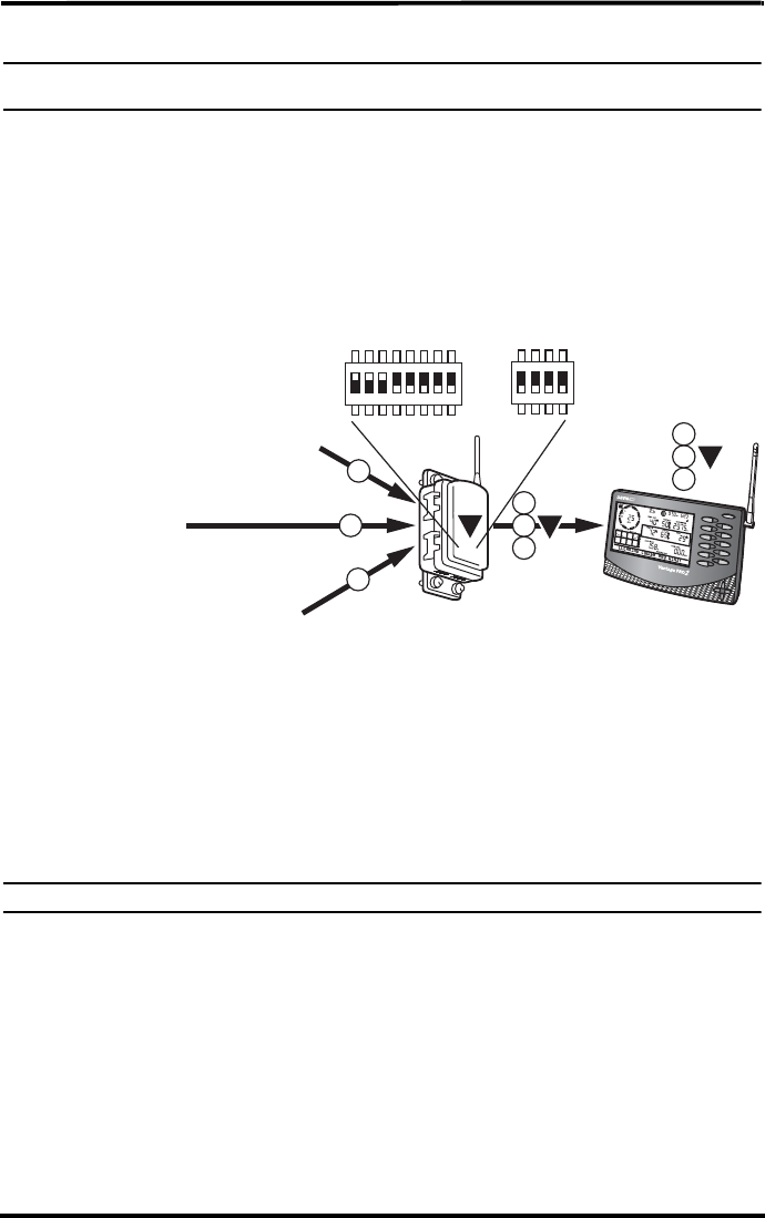
Repeater Configuration/Architecture
Vantage Pro2 Wireless Repeaters are used to enhance the transmission range and capabil-
ities between a station, or multiple stations, and a console. A repeater receives signals
transmitted from a Vantage Pro2 station and retransmits it to a console, wireless Vantage
Pro2 Envoy, or another repeater. Depending on transmission distance, one repeater or
several repeaters can be used to collect and retransmit weather data.
This section describes some of the Vantage Pro2 transmission situations and station net-
works in which a repeater or set of repeaters can be used.
Repeater Architecture
Two general types of repeater configurations are discussed in this chapter: Single
Repeater configurations and Advanced Repeater configurations. A single repeater con-
figuration describes any situation in which one repeater is needed to transmit a signal
from one station to one receiver (console or Envoy).
Advanced repeater configuration describes any architecture where one or more stations
and one or more repeaters are combined to form a network of transmitters. For example,
if a station is placed some distance away from a console that a single repeater is not in
range of the console, multiple repeaters can be set up across the distance to transmit
weather data to the console, in a chain. Another advanced repeater configuration might
involve one or more stations transmitting to a repeater. It is also possible to create a net-
work using a combination of multiple transmitters and repeaters.
Note: All range estimates used in the examples below are based on the maximum “line of sight” transmis-
sion distance of 1000’. Transmission distance vary based on location and site limitations.
Refer to the repeater configuration section that best suits the intended repeater applica-
tion.
Single Repeater Configuration
Use a single repeater as part of a single station, single console setup when the distance
between that station and the console is greater than the maximum transmission distance
of 1000' but less than 2000', where one station can not successfully communicate with a
receiver.
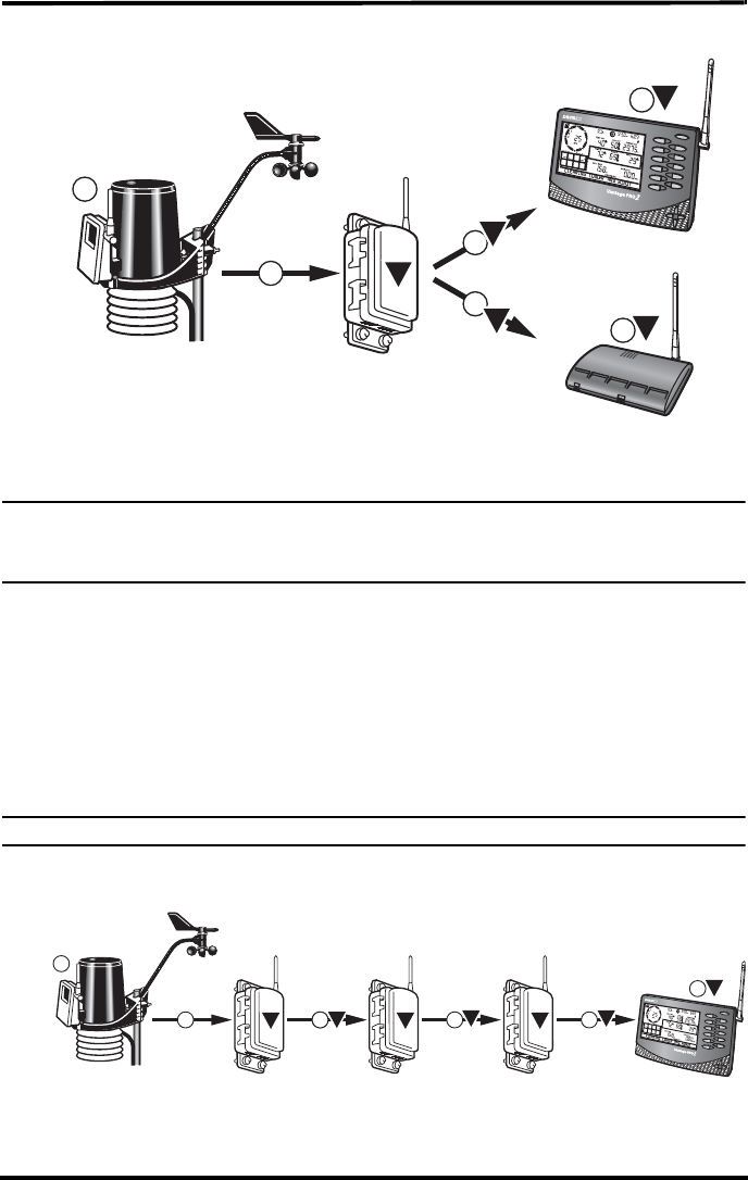
5
The block diagram below shows the typical single repeater configuration:
This configuration allows for greater distances between a station and a console. The dis-
tance gained between the station and the console is up to 1000' more.
Note: The maximum distance allowable in a single repeater configuration is 2000’. If the distance between
a station and a console is more than 2000’, see “Multiple Repeater (Daisy-Chain) Configuration”
below. If more than one station exists, see “Multiple Stations, One Repeater Configuration” on
page 6.
Advanced Repeater Configurations
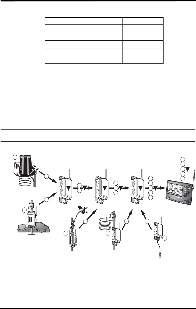
Multiple Repeater (Daisy-Chain) Configuration
More than one repeater should be used to transmit weather information from station to a
console if the distance between the station and console is greater than 2000' (a single
repeater configuration distance), or if they are not in line of sight of each other. A multi-
ple repeater or daisy-chain configuration can create a transmission distance of up to 9000'
using the maximum of eight repeaters.
Note: The limit of eight repeaters is based on the number of unique repeater IDs available in a network.
The block diagram below shows the typical daisy chain configuration:
Any Vantage Pro2
Station
Repeater
1
1
1
1
1
AOR
Vantage Pro2
Console/Receiver
Weather Envoy
A
A
A
1A
Repeater
1 1
1
C
Repeater
1B
1
Any Vantage Pro2
Station
Repeater
1
1A
Vantage Pro2
Console/Receiver
ABC
C
6
The above diagram displays an example daisy chain configuration of one station and
three repeaters, creating a total line of sight transmission distance of 4000'. This configu-
ration allows more flexibility between a station and a console. The distance gained
between the station and the console is up to 1000' more per each repeater that is added to
the network.
Multiple Stations, One Repeater Configuration
One repeater can be used to transmit weather information from multiple stations to a con-
sole if the repeater is within a 1000' line-of-sight radius of each station. The repeater can
transmit and repeat weather data from up to 8 different weather stations.
The block diagram below shows the multiple station configuration:
The above diagram displays an example multiple transmitter configuration of three sta-
tions and one repeater, with the repeater within a 1000' line-of-sight distance of all three
stations and the console, giving an effective distance of up to 2000' for a complete config-
uration.
The repeater can receive signals from up to eight stations/transmitters of any type. How-
ever, there are some limitations as to how many and what type of transmitters the receiver
Temp/Humidity
Station
or
Temperature
Station
Leaf & Soil Moisture
Station
or
Anemometer
Transmitter Kit
Vantage Pro2
Station
Repeater
1
2
3
2
1
3
A2
1
3
2
1
3
Vantage Pro2
Console/Receiver
A
A
7
can listen to. The table below lists the maximum number of transmitters allowable for
one receiver:
Maximum Number of Transmitters in a network with one receiver
*Allowable only if the stations are used in combination, not two of the same kind. For example, A netowrk can
have both a Leaf Wetness/Temperature station and a Soil Moisture/Temperature station, but not two Soil Mois-
ture/Temperature stations.
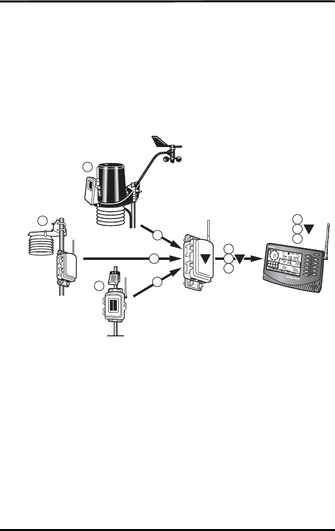
Combination Network Configurations
Given the flexibility of the repeater to listen to more than one station and to transmit to
other repeaters, both stations and repeaters can be set up to create a variety of transmitter
networks to transmit to one receiver. Up to eight repeaters and eight stations can be con-
figured to transmit to one receiver in a variety of ways.
Note: The limit of eight stations and eight repeaters is based on the number of unique stations identifica-
tions available in a network.
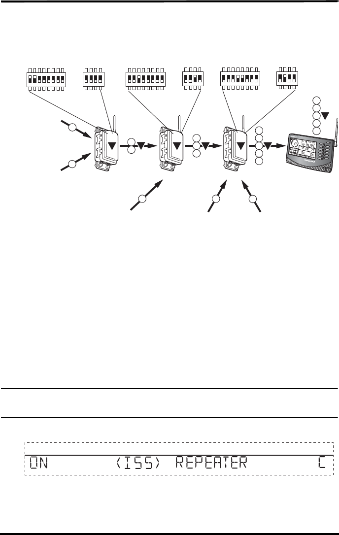
The block diagram below shows a sample combination network:
The above diagram displays an example multiple transmitter/repeater configuration of
five stations and three repeaters, with repeaters listening to stations and other repeaters,
each repeater and station must be within the 1000' line-of-sight range of a repeater.
A repeater can receive signals from up to eight stations/transmitters total, but there is also
a limit on the number of certain types of transmitters. See “Maximum Number of Trans-
mitters in a network with one receiver” on page 7 for the transmitter limitations.
Transmitter Type Maximum Number
Integrated Sensor Suite (ISS) 1
Anemometer Transmitter Kit 1
Leaf & Soil Moisture/Temperature Station* 2
Temperature Station 8
Temperature/Humidity Station 8
Temp/Humidity
Station
Leaf & Soil Moisture
Station
Vantage Pro2
Station
RepeaterRepeater
2
4
45
C3
3
B
Repeater
1
1
2
A
2
1
4
5
3
4
3
2
1
5
Vantage Pro2
Console/Receiver
Temperature
Station
Anemometer
Transmitter Kit
2
1
23
1
AB C
C
5

8
There is also a maximum of eight repeaters allowable in a network.
Note: Although one repeater can listen to multiple transmitters at a time, it can only listen to one other
repeater.
Implementing a Configuration
Once a configuration has been chosen that best suits the needs of the desired station/con-
sole setup, installing and verifying communication between the repeater(s) and station/
stations is the next step. See the section for the installation process best suited to the con-
figuration type chosen:
• See page 8 for a single repeater installation.
• See page 13 for a “daisy-chain” installation.
• See page 15 for a multiple station, single repeater installation.
• See page 17 for a combination network installation.

8
Single Repeater Installation
A single repeater installation is used in situations where one station can not successfully
communicate with a receiver, or if a station needs to be farther away from a receiver than
maximum line-of-sight transmission distance of 1000'. The repeater can also be used as a
signal amplifier for situations in which a signal is weak between a station and a receiver.
Verify Transmitter ID
The wireless repeater listens to and communicates with a station transmitter by looking
for that station’s unique station ID. Each wireless transmitting station, including the Inte-
grated Sensor Suite (ISS), uses one of eight selectable transmitter IDs. The transmitter ID
is set using a four-position DIP switch on the station’s transmitter board, known as a Sen-
sor Interface Module (SIM).
There are two ways to find out the station ID the station is currently transmitting on:
• Checking the DIP switch positions on the station
• Viewing stations transmitting to the console
Checking DIP Switch Positions on a Station
Every Vantage Pro2 station contains a DIP switch used to program the sta-
tion to transmit using a certain ID. DIP switches #1, 2 and 3 on the transmit-
ter control the channel the station transmits on. (DIP switch #4 is used for
transmission testing, not for programming the transmitter ID.)
To find the transmitter ID on your station:
1. Find the white box housing the SIM for your station and open it.
2. Locate the four-position DIP switch, usually located in the right-hand corner of a sta-
tion’s board.
The positions of switches #1,2, and 3, determine the ID the station is set to. The
default transmitter ID for all stations is 1 and the default position for all of the DIP
switches is down or OFF.
1234
ON

9
Use this table to determine which ID the transmitter is using based on the position of
the #1, 2, and 3 switches on the DIP switch.
3. Use the “Transmitter and Repeater ID Worksheet” to record the transmitter ID.
Optional: Changing Transmitter ID
If there is any reason that the transmitter ID needs to be set to another channel, the DIP
switch should be set now to the desired ID.
To change to another ID:
1. Use a paper clip to toggle DIP switches #1, 2, and 3 using the Transmitter ID table
above to change the station to the desired transmitter ID.
The transmitter ID can be changed if any of the following issues are true:
Another Davis Instruments wireless weather station operating nearby already
uses transmitter ID 1.
Additional wireless transmitting stations have been purchased with the Vantage
Pro2 or Vantage Pro2 Plus and one of the stations has been designated as Station
No. 1 instead of the selected ISS.
Viewing stations transmitting to the console
If the station is too far away or in an inconvenient location, making it hard to view the
transmitter ID from the station, the console can be used to determine the transmitter ID.
To find the transmitter ID using the console:
1. Place the repeater in an area where it is likely to receive the transmitter signal.
2. On the console, press the Done and down arrow (-) keys at the same time. The first
screen in the Setup Mode is displayed. This screen locates and eventually displays all
the active transmitter IDs the console is receiving. See the Vantage Pro2 Console
Manual for more information about the Setup Mode and the Active Transmitter screen
if necessary.
3. Record the value of the transmitter ID.
ID CODE SWITCH 1SWITCH 2SWITCH 3
1 (default) off off off
2offoffON
3offONoff
4 off ON ON
5ONoffoff
6ONoffON
7ONONoff
8ONONON

10
Verifying Repeater ID
The wireless repeater contains a DIP switch used to give the repeater a unique identifica-
tion. DIP switches #1, 2, and 3 on the repeater are used in the same way that DIP switches
are used on all stations.
Note: For single repeater installations, the repeater should remain on the default ID of A and should not
be changed.
Verify that the repeater DIP switches are all in the down position or OFF.
The repeater has the default ID of A and communication testing can continue as planned.
If any of the three switches are on in any combination, switch them off. Refer to the table
marked “Repeater ID DIP Switch Positions” on page 13
Verifying Communication with a Transmitter
Once the transmitter ID has been verified or changed for use with the wireless repeater, it
is time to program the wireless repeater with the station ID information. To do this:
1. Have the repeater placed in an area where it is likely to receive the transmitter signal.
2. Open the wireless repeater box and locate the four-position Repeater ID DIP switch
next to the eight-position transmitter ID switch at the bottom of the repeater board.
3. Turn the #4 test position to ON. This test switch enables the TX and STAT LEDs.
They display light patterns based on the behavior of the wireless repeater and how it is
receiving signals from the transmitter.
4. Turn the Transmitter ID to ON for the desired station and make sure all the other trans-
mitter IDs are in the OFF position. The following graphic demonstrates the Transmit-
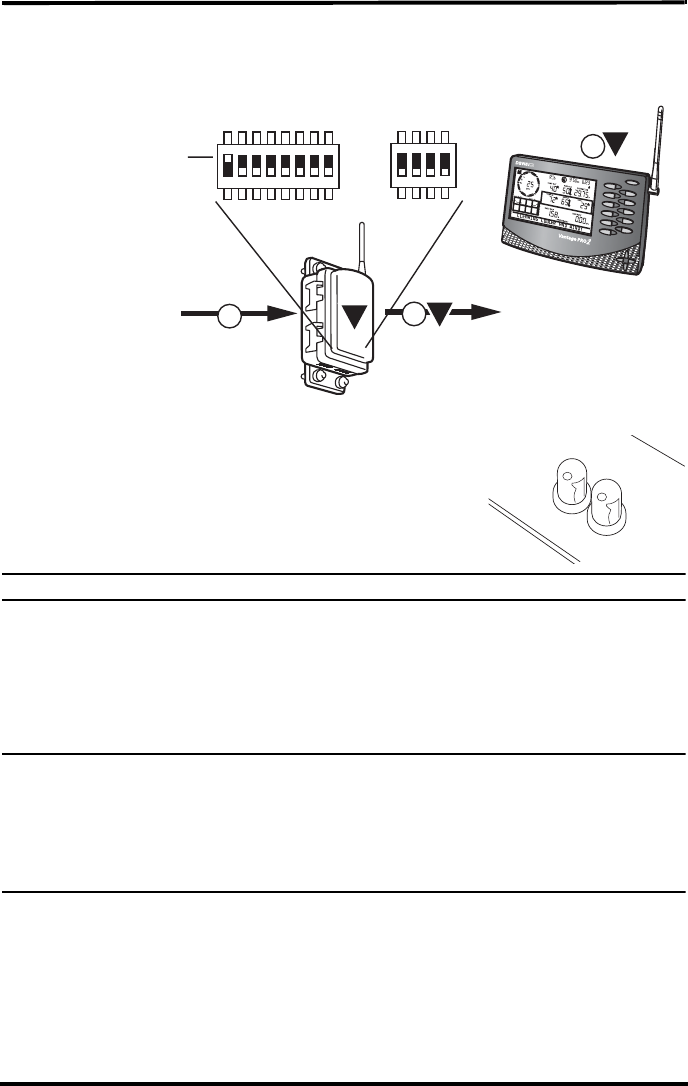
11
ter DIP and Repeater DIP switch positions for a normal single installation
configuration:
The Status LED blinks red when it detects some radio
energy, until the repeater receives the desired transmitter.
When a packet of information has been fully received from
the transmitter, the Status LED blinks green and the TX
LED blinks, indicating that it is sending the information it
has received from the transmitter to a console.
Note: See “Maintenance and Troubleshooting” on page 25 if the LED pattern does not display.
5. Turn the #4 test position to OFF once the test is complete, otherwise it can drain the
battery power.
Verifying Repeater Communication with a Console
Once the repeater is successfully communicating with a transmitter, the console should
be set up to receive the transmitter data through the repeater.
Note: Not all consoles have the capability to access wireless repeater information. If your console or
Envoy has firmware older than May 2005, it does not have the capability to see and configure Van-
tage Pro2 wireless repeaters. To check your console’s firmware, press the DONE and up arrow (+)
keys. The firmware revision displays in the ticker tape section of the console. To check your Envoy’s
firmware in WeatherLink, Select Console Diagnostics from the Reports Menu and view the firmware
date displayed. If the console or Envoy firmware version is older than May 2005, a Vantage Pro2
updater can be used to update the console or Envoy. Contact Technical Support about acquiring an
updater for your console or Envoy.
On the Console:
1. Press DONE and the down arrow (-) to display the console’s Setup Mode. Screen 1:
Active Transmitters is the first screen. This screen displays only the active stations the
console is receiving. Wireless repeater identification is not displayed on this screen.
Any Vantage Pro2
Station
Repeater
11
1
A
Vantage Pro2
Console/Receiver
A
A
Transmitter DIP
Switch with ID 1 ON
Repeater DIP
Switch set to ID A
ON
TX STAT
12
The transmitter ID for the station set on the repeater should display on this screen,
with the number displaying above the ticker tape and an “X” displaying on the bottom
right of the console screen. If the transmitter ID is not displayed in this screen, see
“Maintenance and Troubleshooting” on page 25.
2. Press DONE to display Screen 2: Configuring Transmitter IDs.
3. Find the transmitter ID transmitting through the repeater using the right (<)and left (>)
arrows, and if the station is not already toggled on with it’s station type selected, do so
now by pressing the up (+) arrow until “ON” displays on the screen. Change the sta-
tion type by pressing GRAPH until the correct station type displays.
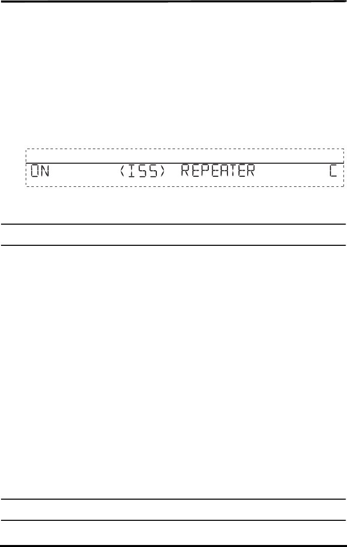
4. Press WIND to turn the repeater function on and to display a repeater ID. Pressing
WIND programs the console to receive the signal from a repeater instead of directly
from a station. The first repeater ID displayed is repeater A and it should be the
selected repeater ID for a single repeater installation.
Note: Pressing WIND repeatedly cycles through all eight repeater IDs possible and then displays no iID in
the right hand corner. When no repeater ID is shown, the console is configured to listen directly to a
station and not to a repeater.
5. Press DONE to continue to the other screens in the Setup Mode, or press and hold
DONE to return to the Current Weather Mode.
Note: See the Vantage Pro2 console manual for more information on the screens in the Setup Mode if
necessary.
To verify that setup was successful, in the console’s current mode:
1. View the transmitter information displaying at the bottom of the console screen.
If the transmitter ID being repeated is displayed and an “X” displays in the bottom
right-hand corner of the ticker tape, the transmitter is being repeated and received by
the console successfully.
Choosing a Location
After wireless communication between the station, wireless transmitter and console has
all been tested, choose a location that best suits the wireless communication needs of all
three units. Choosing a location for the wireless repeater should be based on the follow-
ing requirements:
1

13
• Typical maximum range for the station. The typical range of all Vantage Pro2 stations
are:
Line of sight: 1000' (300 m)
Under most conditions: 200 - 400' (60 - 120 m)
• Typical maximum range for the repeater. The range for a standard wireless repeater
has the same range limitations as all Vantage Pro2 stations.
• The maximum line of sight transmission distance between a transmitter and a
receiver using one wireless repeater is 2000'.
Other range and transmission considerations include:
• Range may be reduced by walls, ceilings, trees, foliage, hills, a metal roof or other
large metal structures or objects such as aluminum siding, metal ducts, and metal
appliances.
• Frequency interferers also reduce transmission distance. Cordless phones (900 Mhz)
and wireless computer connections are two types or frequency interference.
• Transmission between wireless units may be obscured by something unidentifiable,
or by some obstacle that can’t be worked around.
• For best results, orient all antennas so that the angles of the antennas are parallel to
each other.
• If possible, align the pivot joints of the antennas so that they are facing each other for
maximum signal strength.
• If possible, mount the wireless repeater as high as possible (on a pole or atop a build-
ing) to overcome transmission limitations on the ground. See “Mounting the Wireless
Repeater” on page 20 for more information.
Testing a Proposed Location
After a suitable location has been chosen in an area between the station and console, it is
very important to test reception between the station, repeater, and console before perma-
nently mounding the repeater.
1. Hold the repeater in the desired installation location.
2. Place the repeater back in test mode if test mode has been turned off. If the repeater
LEDs blink the normal operation light pattern, the repeater is successfully receiving a
signal from the station.
3. In the console’s Current Weather Mode, view the station ID number displaying in the
bottom of the screen. If the station ID displaying is the station transmitting through the
repeater, the console is successfully receiving a signal from the wireless repeater.
13
Advanced Repeater Installation
Installing more than one repeater, or getting a repeater to receive signals from multiple
stations/repeaters, follows the same basic processes used to install the a single repeater
into a single transmitter/single console network.
See the desired advanced repeater installation for complete instructions.
Multiple Repeater (Daisy-Chain) Installation
A daisy-chain installation is very similar to a single repeater installation with the excep-
tion of the number of repeaters involved. See “Single Repeater Installation” on page 8 for
detailed instructions on configuring the transmitter and console for wireless repeater use.
This section covers the additional steps necessary to get a chain of repeaters set up and
communicating.
Verifying/Changing Repeater IDs
In a daisy-chain installation, a unique repeater ID is required for every repeater that is
part of the chain.The first repeater, the repeater closest to the transmitter must have the
default repeater ID of A. The next repeater in the chain must be programmed with the
repeater ID of B. The repeater that is set to the default of A is set up to only look for and
acquire signals from the transmitter. The repeater with repeater ID of B looks for a
repeater with the ID A automatically, and so on down the line.
Note: Each repeater will only look for and acquire signals from the previous repeater in the chain.
To set the repeater IDs for all of the repeaters in the chain:
1. Identify the repeater that will be positioned closest to the transmitter and open it.
2. Verify that the repeater DIP switch in this repeater unit is set to the default ID of A (all
DIP switches on the OFF position).
3. Identify the next repeater in the chain and open it.
4. Change the Repeater ID to B using the table below:
Repeater ID DIP Switch Positions
REPEATER ID CODE SWITCH 1SWITCH 2SWITCH 3
A (default) off off off
BoffoffON
CoffONoff
D off ON ON
EONoffoff
FONoffON
GONONoff
H ONONON

14
5. Continue setting the next sequential repeater ID for each repeater in the chain.
Verifying Communication with a Transmitter and
Repeaters
Note: The repeater that received the default ID of A is the only transmitter in the network that must be con-
figured with the station’s Transmitter ID.
1. Have the first repeater in the chain placed in an area where it is likely to receive the
transmitter signal.
2. Turn the Transmitter ID for the station ON on the Transmitter ID switch.
3. Turn the #4 test position ON on the Repeater ID DIP switch. The Status LED blinks
red until the repeater receives the desired transmitter. When a packet of information
has been fully received from the transmitter, the Status LED blinks green and the TX
LED blinks, indicating that it is sending the information it has received from the trans-
mitter to a console.
Note: See “Maintenance and Troubleshooting” if the following LED pattern does not display. Repeater A
should fully acquire a signal from a station before proceeding to the next repeater in the chain, oth-
erwise the second repeater in the chain will have trouble acquiring a signal.
4. Toggle the #4 test position of OFF once the test is complete, otherwise it can drain the
battery power.
5. Select the second repeater in the chain (Repeater ID B) and toggle the #4 test position
on Repeater ID DIP switch to ON. The Status LED displays the same light pattern dur-
ing its acquisition phase as described above.
6. Repeat the test process to verify communication for every repeater in the chain.
Note: Set the Transmitter ID for only one repeater (first repeater) in the chain. The second repeater in the
chain automatically repeats the first repeater and the station the it is communicating with.
Use the following diagram for an example of transmitter and repeater DIP switch settings
for each repeater in a daisy chain.
Repeater
1 1
1
C
Repeater
1B
1
A
ny Vantage Pro2
Station
Repeater
1A
Vantage Pro2
Console/Receiver
ABC
C
Transmitter DIP
Switch with ID 1 ON
Repeater DIP
Switch set to ID A
Transmitter DIP Switch
All IDs OFF
Repeater DIP
Switch set to ID B
Transmitter DIP Switch
All IDs OFF
Repeater DIP
Switch set to ID C
15
Verifying Repeater Communication with a Console
The console is configured the same way it is configured in a Single Repeater installation,
except that the repeater ID that is selected is the last repeater in the chain.
On the Console in Screen 2: Configuring Transmitter IDs:
1. Find the transmitter ID transmitting through the repeater, and if the station is not
already toggled on with it’s station type selected, do so now. Turn the station on by
pressing the up arrow until “ON” displays on the screen. Change the station type by
pressing GRAPH until the correct station type displays.
2. Press WIND to turn the repeater function on and to display repeater ID information.
Keep pressing WIND until the Repeater ID for the last repeater in the chain is dis-
played.
3. Press DONE to continue to the other screens in the Setup Mode, or press and hold
DONE to return to the Current Weather Mode.
Note: See the Vantage Pro2 console manual for more information on the screens in the Setup Mode if
necessary.
To verify that setup was successful, in the console’s current mode:
1. View the transmitter information displaying at the bottom of the console screen.
If the transmitter ID being repeated is displayed and an “X” displays in the bottom
right-hand corner of the ticker tape, the transmitter is being repeated and received by
the console successfully.
Multiple Transmitters, One Repeater
Installation
A multiple transmitter, one repeater installation differs from a single repeater installation
only in the number of transmitters the repeater listens to and retransmits. See “Single
Repeater Installation” on page 8 for detailed instructions on configuring the transmitter
and console for wireless repeater use.
This section covers the additional steps necessary to get a chain of repeaters set up and
communicating.
Verifying Repeater ID
The wireless repeater contains a DIP switch used to program the repeater with a unique
identification. DIP switches #1, 2 and 3 on the repeater are used in the same way that DIP
switches are used on all stations.The default repeater ID is A and the default position for
the DIP switches is down or OFF
Note: For Single Repeater Installations, the repeater should remain on the default ID of A and should not
be changed.
1
16
Verifying communication with multiple transmitters
Note: All transmitters in the network must have unique IDs in order for any repeater to communicate with
them.
1. Find out and record all the transmitter IDs the wireless repeater will transmit. Use the
“Transmitter and Repeater ID Worksheet” to record the transmitter IDs used. See
“Verify Transmitter ID” on page 8 for information on determining the transmitter ID
for all stations in the network.
2. On the Transmitter ID switch, set all the Transmitter IDs you want the repeater to
acquire ON.
3. Turn the #4 test position to ON on the Repeater ID DIP switch. When trying to acquire
stations, the repeater goes through the following process:
• Looks for a station signal for ten minutes, with the STAT LED flashing red when
it detects energy not associated with a station during this time.
• Flashes yellow if it has found some stations but not all, and then;
• Flashes green when all stations are found. For each station found, the TX LED
flashes immediately after the STAT LED, indicating that it is transmitting the
station ID(s).
Note: See “Maintenance and Troubleshooting” on page 25 if the following LED pattern does not display.
4. Turn the #4 test position to OFF once the test is complete, otherwise it can drain the
battery power.
5. Repeat the test process to verify communication for every repeater in the chain.
Verifying Repeater Communication with a Console
The console is configured the same way it is configured in a Single Repeater installation,
except that the repeater ID must be set for all station that are being repeated.
On the Console in Screen 2: Configuring Transmitter IDs:
1. Find the transmitter ID transmitting through the repeater, and if the station is not
already turned on with it’s station type selected, do so now. Turn the station on by
Repeater
2
1
3
A2
1
3
2
1
3
Vantage Pro2
Console/Receiver
A
A
Any Vantage Pro2
Station
Any Vantage Pro2
Station
Any Vantage Pro2
Station
Transmitter DIP
Switch with
IDs 1, 2, 3 ON
Repeater DIP
Switch set to ID A

17
pressing the up arrow until “ON” displays on the screen. Change the station type by
pressing GRAPH until the correct station type displays.
2. Press WIND to turn the repeater function on and to display repeater ID information.
The first repeater ID displayed is Repeater A, which is the default.
3. Find the second transmitter ID, and if that station is not turn on with it’s station type
selected, do so now.
4. Press WIND to turn on the repeater function and display the repeater ID information
for that transmitter.
5. Continue selecting, turning on and enabling the repeater function for each transmitter
in the network.
6. Press DONE to continue to the other screens in the Setup Mode, or press and hold
DONE to return to the Current Weather Mode.
Note: See the Vantage Pro2 console manual for more information on the screens in the Setup Mode if
necessary.
To verify that setup was successful, in the console’s current mode:
1. View the transmitter information displaying at the bottom of the console screen.
If the transmitter ID being repeated is displayed and an “X” displays in the bottom
right-hand corner of the ticker tape, the transmitter is being repeated and received by
the console successfully.
Combination Network (Multiple Transmitters/
Repeaters) Installation
A multiple transmitter, multiple repeater installation can take place any number of ways
with some repeaters receiving both repeaters and transmitters. See “Single Repeater
Installation” on page 8 for detailed instructions on configuring the transmitter and con-
sole for wireless repeater use.
This section covers the additional steps necessary to get a chain of repeaters set up and
communicating.
Verifying/Changing Repeater IDs
A combination network installation requires that the first repeater, the repeater closest to
the first transmitter in the network, must have the repeater ID of A. The next repeater in
the chain must be programmed with the repeater ID of B. The repeater that is set to the
default of A is set up to only look for and acquire signals from the transmitters. The
repeater with ID B looks for a repeater with the repeater ID of A, and any transmitters it
is programmed to receive.
To set the repeater IDs for all of the repeaters in the network:
1. Identify the repeater that should be the first repeater in the network.
2

18
2. Verify that the repeater DIP switch in this repeater is set to the default ID of A (all DIP
switches on the OFF position).
3. Identify the next repeater in the network and open it.
4. Change the Repeater ID to B.See the table marked “Repeater ID DIP Switch Posi-
tions” on page 13.
5. Continue setting repeater IDs for each repeater in the chain.
Verifying communication with multiple transmitters
Note: All stations in the network must have a unique ID in order for one repeater to communicate with them.
1. Find out and record all the transmitter IDs the wireless repeater or repeaters will
transmit. Use the “Transmitter and Repeater ID Worksheet” to record the transmitter
IDs used. See “Verify Transmitter ID” on page 8 for information on determining the
transmitter ID for all stations in the network.
2. On the Transmitter ID switch on the first repeater (repeater A), turn on all the Trans-
mitter IDs you want to acquire to ON.
3. Turn the #4 test position to ON on the Repeater ID DIP switch. When trying to acquire
stations, the repeater goes through the following process:
• Looks for a station signal for ten minutes, with the STAT LED flashing red when
it detects energy not associated with a station during this time.
• Flashes yellow if it has found some stations but not all, and then;
• Flashes green when all stations are found. For each station found, the TX LED
flashes immediately after the STAT LED, indicating that it is transmitting the
station ID(s).
Note: See “Maintenance and Troubleshooting” on page 25 if the above LED pattern does not display.
4. Toggle the #4 test position of OFF once the test is complete, otherwise it can drain the
battery power.
5. Select the second repeater in the chain (Repeater ID B) and turn the #4 test position
Repeater ID DIP switch ON and any transmitter it will receive that is not already
transmitting through repeater A. The Status LED displays the same light pattern dur-
ing its acquisition phase as described above.
19
Repeat the test process to verify communication for every repeater in the network. Use
the following diagram to verify the repeater and transmitter DIP switch positions in an
example combination network:
Verifying Repeater Communication with a Console
The console is configured the same way it is configured in a Single Repeater installation,
except that the repeater ID that is selected is the last repeater in the chain. and is selected
for all stations being repeated.
On the Console in Screen 2: Configuring Transmitter IDs:
1. Find the transmitter IDs transmitting through the repeaters, and if the stations are not
already toggled on with station types selected, do so now. Turn a station on by
pressing the up arrow until “ON” displays on the screen. Change the station type by
pressing GRAPH until the correct station type displays.
2. For each transmitting station, press WIND turn the repeater function on and to display
repeater ID information. Keep pressing WIND until the Repeater ID for the last
repeater (repeater closest to the console) is displayed.
Note: Even if there are multiple repeaters transmitting multiple stations, the only repeater that needs to be
programmed into the console is the last repeater in the chain, the repeater that is the closest to the
console.
3. Continue selecting, turning on and enabling the repeater function for each transmitter
in the network.
4. Press DONE to continue to the other screens in the Setup Mode, or press and hold
DONE to return to the Current Weather Mode.
RepeaterRepeater
45
C3
3
B
Repeater
1
2
A
2
1
4
5
4
3
2
1
5
Vantage Pro2
Console/Receiver
2
1
23
1
AB C
C
Any Vantage Pro2
Station
Any Vantage Pro2
Station
Any Vantage Pro2
Station
Any Vantage Pro2
Station
Any Vantage Pro2
Station
Transmitter DIP
Switch with
IDs 1, 2 ON
Repeater DIP
Switch set to ID A
Transmitter DIP Switch
with ID 3 ON
Repeater DIP
Switch set to ID B
Transmitter DIP
Switch with
IDs 4, 5 ON
Repeater DIP
Switch set to ID C
1

20
Note: See the Vantage Pro2 console manual for more information on the screens in the Setup Mode if
necessary.
To verify that setup was successful, in the console’s current mode:
1. View the transmitter information displaying at the bottom of the console screen.
If the transmitter ID being repeated is displayed and an “X” displays in the bottom
right-hand corner of the ticker tape, the transmitter is being repeated and received by
the console successfully.
Choosing Locations
Location considerations for every wireless repeater in the network follow the same con-
siderations that a single repeater installation follows. See “Choosing a Location” on
page 11 for mounting considerations and limitations.
Testing Proposed Locations
After a suitable location has been chosen it is very important to test reception between the
stations, repeaters, and a console or Envoy before permanently mounding the repeater.
1. Hold the repeater in the desired installation location.
2. Place the repeater back in test mode if test mode has been turned off. If the repeater
LEDs blink the normal light pattern, the repeater is successfully receiving a signal
from the station.
3. Repeat the process for every repeater in the network.
4. In the console’s Current Weather Mode, view the station ID numbers displaying in the
bottom of the screen. If the station IDs displaying are the stations transmitting through
a network of repeaters, the console is successfully receiving a signals from the wire-
less repeaters and stations.
20
Mounting the Wireless Repeater
The wireless repeater can be installed on a flat surface or on a pole at the locations desig-
nated for installation. Use the U-bolts to install the wireless repeater on a pole or the lag
screws to install the repeater on a flat surface.
General Installation Guidelines
• If the wireless repeater is a solar power unit (#7627) the solar panel should face south
if in the Northern Hemisphere, or north if in the Southern Hemisphere.
• If the wireless repeater is an AC-powered unit (#7626) the wireless repeater, the
installation location should be close enough to an outlet for power.
• Rotate the antenna to the vertical position before mounting.
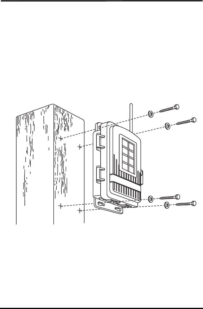
Installing the Repeater on a Flat Surface
Refer to the following illustration to install the repeater on a post or flat vertical surface:
1. With a 3/16'' (5 mm) drill bit, drill four holes approximately 2-1/8'' (54 mm) apart. Use
a carpenter’s level to ensure the holes are level. Use the holes on the wireless repeater
box as a guide when marking the holes.
2. Drill two more holes 7-1/32" below the upper holes.
3. Insert the 1/4" x 1-1/2" lag screws through the flat washers, and through the holes at
the top and bottom of the shelter into the post.
4. Using an adjustable wrench or 7/16" wrench, tighten the lag screws.
Flat
Washer
Lag
Screw
21
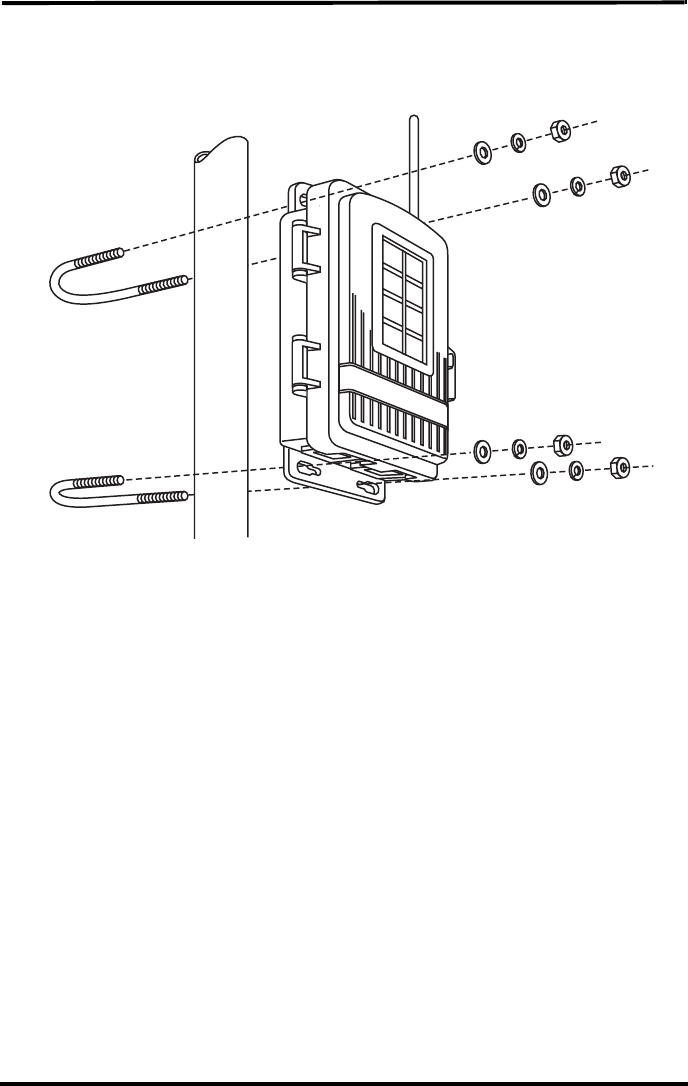
Installing the Repeater on a Pole
Refer to the following illustration to install the repeater on a pole:
1. While holding the shelter against the pole, place a U-bolt around the pole and
through the two holes on at the top of the shelter.
2. Place a flat washer, a lock washer and a hex nut on each of the bolt ends.
3. Using an adjustable wrench or 7/16" wrench, tighten the nuts.
4. Place the second U-bolt around the pole and through the two holes at the bot-
tom of the shelter.
5. Put a flat washer, a lock washer, and a hex nut on each bolt end, and tighten
the hex nuts.
Flat
Washer
Lock
Washer
Hex
Nut
U-Bolt
22
WeatherLink and Console Configuration
The Vantage Pro2 console, Envoy, and corresponding WeatherLink software for Vantage
Pro2 allow you to view the information coming from your network but also allow you to
configure and view information directly related to your repeater network.
Repeater Information on the Console
Once you have configured your console to receive station data through a repeater net-
work, the console keeps track of and displays information related to the wireless repeater,
such as battery life and network signal strength.
Note: For instructions on configuring the console to accept wireless repeater information in Setup Mode,
“Verifying Repeater Communication with a Console” for your network installation type.
Battery Information on the Console
Whenever any station or repeater in the network is running on low battery power, the
console displays a low battery warning for that repeater in the ticker tape in the console’s
current mode:
Note: The console only displays low battery messages for the first four repeaters/stations in the network
that run low on battery power. If there are more than four repeaters/stations in you network experi-
encing low battery power at a time, the console does not display them.
Network Signal Strength
As a diagnostic tool, the console can display the signal strength between a repeater and
the previous transmitter in the network. Using this function lets you analyze the commu-
nication efficiency for repeaters and transmitters in the network.
To view the signal strength between repeater closest to console and the previous transmit-
ter in the chain:
1. Make sure Test Mode is on for the repeater whose signal strength you want to see.
2. With the console in Current Weather Mode, press WIND. The signal strength between
the repeater and the previous transmitter in the chain displays when the degree (º) sign
is visible in the center of the wind compass rose.
A number between 0 and 60 displays. Any value between 20 and 60 is a sign of good
signal strength. If the value is less than 20 or the field is dashed out, the repeater is
having trouble communicating with the previous transmitter in the chain. See “Com-
munication Troubleshooting” on page 25 for information on analyzing and solving
communication problems.
23
Note: The signal strength information will only display in the wind compass if one of the stations the con-
sole is set to receive is configured as an ISS or Anemometer Transmitter Station. Display Screen 2
of the Setup Mode to reconfigure a station in the network to an ISS if necessary., redisplay Current
Weather Mode and press WIND again to view the signal strength. If there is more than one station,
reconfigure each station the same way and repeat the process.
Repeater Functionality in WeatherLink
WeatherLink software lets you configure and maintain the network or repeaters and sta-
tions in the same way that the console is configured. WeatherLink also monitors the bat-
tery life of all transmitters and repeaters in the network.
Note: If your network of transmitters and repeaters is communicating with an Envoy, WeatherLink is the
only way the repeater and transmitter information is configured on the Envoy. If your Envoy has
firmware older than May 2005, it does not have the capability to see and configure Vantage Pro2
wireless repeaters. To check your Envoy’s firmware in WeatherLink, Select Console Diagnostics
from the Reports Menu and view the firmware date displayed. If the Envoy firmware version is older
than May 2005, a Vantage Pro2 updater can be used to update the Envoy. Contact Technical Sup-
port about acquiring an updater for your Envoy.
Only versions of WeatherLink 5.6 or later have the capabilities necessary to configure
and monitor repeater use.
Configuring Repeaters
With a console or Envoy connected to your computer via serial or USB data logger:
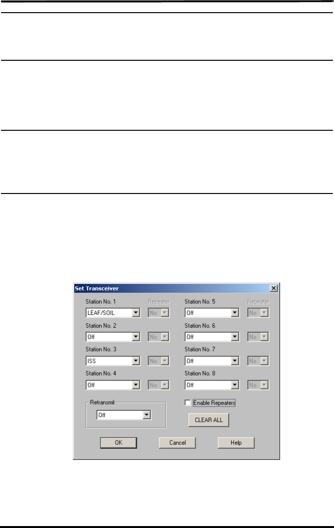
1. Select Set Transceiver from the Setup Menu. The Set Transceivers dialog box
displays
2. Click the Enable Repeaters check box. The Repeater drop down boxes are enabled
for the available stations.
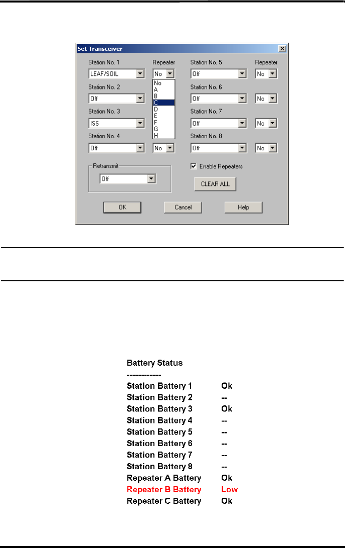
24
3. Select the repeater identification the station is using to communicate to the console or
receiver.
Note: The repeater selected for the station should be the repeater closest to the console or receiver. For
example, in a daisy chain of one station and three repeaters, the last repeater in chain is the
repeater that should be selected.
4. Continue selecting the correct repeater ID for each station in the network. Click OK to
save the settings and exit the dialog box.
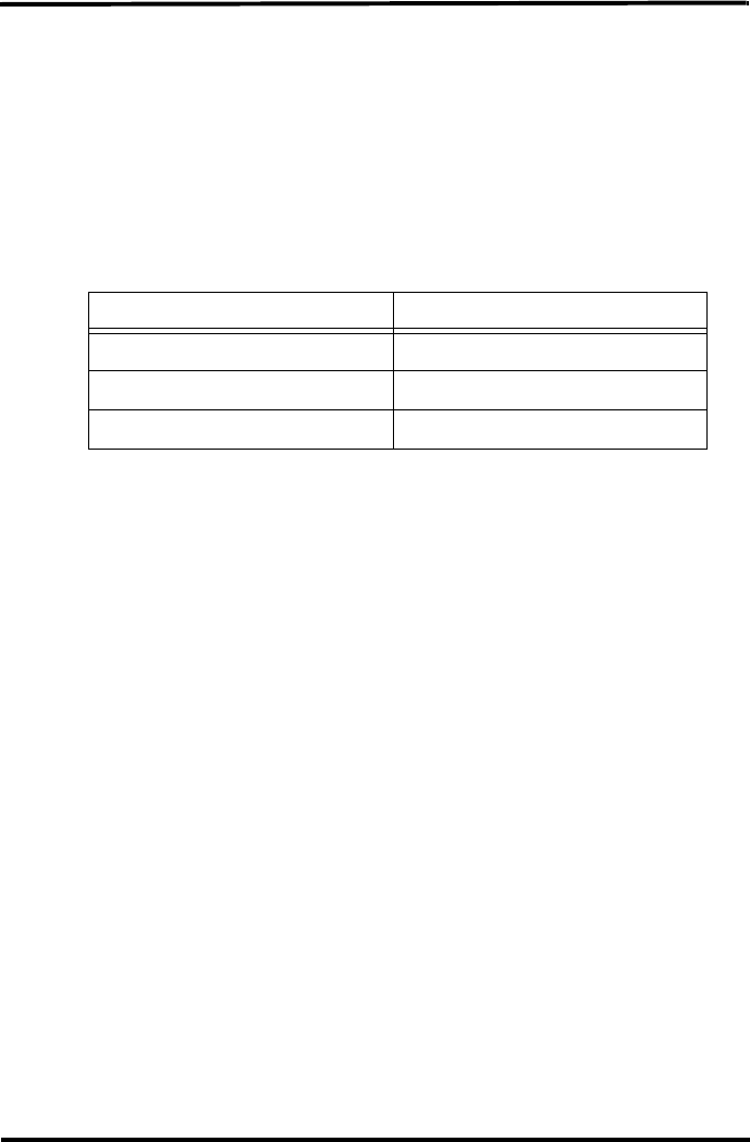
Monitoring Repeater and Station Battery Life
1. Select Alarm and Battery Status from the Window Menu. The Alarm and Battery
Status window displays:
Battery status displays for every station and repeater selected in the Set Transceiver
dialog box.

25
Maintenance and Troubleshooting
Communication Troubleshooting
Depending on the complexity of the repeater network, communication problems between
the transmitter(s), repeater(s), and console could consist of a number of factors. To solve
communication problems in the network, the transmitter, repeater or console causing
communication problems must be isolated. Use the following table to help determine
which part of the network might be causing problems:
Repeater Troubleshooting Error Codes
In addition to showing normal communication, the TX and STAT LEDs can display error
codes corresponding to configuration or communication problems when the repeater is in
Test Mode. The STAT LED flashes numbered error codes in red or yellow. After the error
code is displayed by the STAT LED, the TX LED may flash the corresponding transmit-
ter or repeater ID associated with the error.
The error codes are listed by the number of STAT LED flashes.
Error Type Problem Solution
Station Error
Transmission Error Station not transmitting.
Turn on station’s test mode and de-
termine if station is transmitting. If
not, replace batteries, and make
sure a console can directly receive
its signal. If not, call technical sup-
port.
Repeater Errors
Transmission Errors Repeater is receiving signal from
station. Move repeater to find signal.
User Errors Station or repeater ID information
not set correctly on repeater, or
repeaters.
Check station IDs on repeater, ver-
ify repeaters are set up sequential-
ly. See error codes below for list of
errors and solutions.
Product Errors Faulty product, the repeater never
gets a signal.
If possible, use a Vantage Pro2 up-
dater to do a firmware update on
the console or repeater. If still ex-
periencing problems, call technical
support.
Console Errors
Transmission Errors Console not in range of repeat-
er(s).
Use console diagnostic screen to
determine strength of signal. Call
technical support.
User Errors Repeaters and/or stations not
configured in Setup Mode or con-
figured incorrectly.
In Screen 2 of Setup Mode, recon-
figure the station and repeater in-
formation.

26
Error 1 (One Flash)
Problem
Station ID or IDs not found.
Repeater Behavior
When trying to acquire stations, the repeater looks for a station signal for ten minutes.
During this time, the STAT LED flashes red when it detects energy not associated with a
station. It flashes yellow if it has found some stations but not all, and green when all sta-
tions are found. For each station found, the TX LED flashes immediately after the STAT
LED, indicating that it is transmitting the station ID(s).
After ten minutes, the STAT LED flashes red once if it has not found any of the station
IDs it is looking for or yellow once if it has found some of the station IDs but not all. The
TX then flashes the Station ID(s) it can not find. The pattern repeats for 15 minutes, after
which the repeater will spend another two minutes looking for the stations.
Note: Changing any of the settings on either the Transmitter DIP switch or Repeater DIP switch resets the
repeater and begins the 10 minute acquisition process again.
Solution
The repeater is not in range to receive signals from a station or stations or the station ID is
not set correctly on the repeater. Try moving the repeater for better reception or check the
Transmitter DIP switch to make sure the correct stations are turned on and any station ID
that does not exist in your network is not turned on.
Error 2 (Two Flashes)
Problem
Station ID is duplicated between two repeaters in a chain.
Repeater Behavior
If two repeaters are programmed to receive the same station, the second repeater in the
chain ignores the signal it is receiving from the station and repeats the signal it receives
from the previous repeater instead.
The the STAT LED on the second repeater flashes yellow twice. The TX LED then
flashes the Station ID that is duplicated on the repeater.
Solution
Turn off the Station ID on the second repeater. The second repeater automatically
receives the signal from the previous repeater in the chain and does not need the Station
ID.
Error 3 (Three Flashes)
Problem
Repeater ID or repeated Station IDs are not found.
Repeater Behavior
When trying to acquire other repeaters or repeated stations, the repeater looks for a signal
from a repeater for ten minutes. During this time, the STAT LED flashes red if it has not
found any station or repeater signal. It flashes yellow if it has found some station or
repeater signals but not all. If some of the stations are found, the TX LED flashes, indi-
cating that it is transmitting the stations it has found.

27
After ten minutes, The STAT LED flashes red three times if it has not found any signal
from the previous repeater in the chain. It flashes yellow three times if it has found some
of the repeater or station IDs but not all. If the repeater flashes red the TX does not flash.
If it flashes yellow, the TX then flashes the repeater ID it can not find.
Solution
The repeater is not in range to receive signals from the previous repeater or the repeaters
are not programmed in sequential order. Try moving the repeater for better reception or
check the Repeater DIP switch for each repeater to make sure the repeater has the correct
ID.
Error 4 (Four Flashes)
Problem
No station IDs have been set on the first repeater (repeater A).
Repeater Behavior
The STAT LED flashes RED four times and the TX LED remains off.
Solution
Turn on the correct station ID on the Transmitter ID Switch for the first repeater in the
chain (repeater A).
Repeater Maintenance
Use the following maintenance routine on a regular basis to prolong the life of all repeat-
ers in your network:
• Replace batteries on a routine basis based on the number of transmitters
communicating with a single repeater. See the Battery Life Expectancy table in
Appendix A for more information. Also, use the console to determine when to
change repeater batteries (see “Battery Information on the Console” on page 22).See
“Applying Battery Power” on page 2 for instructions on replacing the battery.
• Use a damp cloth to clean the solar power cell and all surfaces of the repeater box
when replacing the battery.
• Open the repeater box and remove any debris or buildup inside.
Contacting Davis Technical Support
If you have any questions, or encounter problems installing or operating your Vantage
Pro 2 weather station, please contact Davis Technical Support. We’ll be glad to help.
(510) 732-7814 — Monday - Friday, 7:00 a.m. - 5:30 p.m. Pacific Time. We are unable to
accept collect calls.
(510) 670-0589 — Technical Support Fax.
support@davisnet.com — E-mail to Technical Support.
info@davisnet.com — General e-mail.
www.davisnet.com — Davis Instruments web site.
See the Weather Support section for copies of user manuals, product specifications, appli-
cation notes, and information on software updates. Watch for FAQs and other updates.
28
Appendix A
Specifications
Complete specifications for all of the Vantage Pro2 weather products as well as the wire-
less repeater are available in the Weather Support section of our website:
http://www.davisnet.com/support/weather/
General
Operating Temperature. . . . . . . . . . . . . . . . . . -40 to 150° Fahrenheit (-40 to 65° Celsius)
Non-operating Temperature . . . . . . . . . . . . . . -40 to 150° Fahrenheit (-40 to 65° Celsius)
Current Draw . . . . . . . . . . . . . . . . . . . . . . . . . 1.5 mA at 4-6 VDC
Batteries . . . . . . . . . . . . . . . . . . . . . . . . . . . . . CR 123A 3-volt lithium battery
Battery Life Estimates (with no solar or AC power input):
Solar Panel . . . . . . . . . . . . . . . . . . . . . . . . . . . 0.5 Watts
Alternate power. . . . . . . . . . . . . . . . . . . . . . . . AC power adapter
Housing Material. . . . . . . . . . . . . . . . . . . . . . . UV-resistant PVC plastic
Dimensions . . . . . . . . . . . . . . . . . . . . . . . . . . . 6.25'' x 2.25” x 7.88'' (158.75 mm x
57.15 mm x 200.03 mm)
Weight. . . . . . . . . . . . . . . . . . . . . . . . . . . . . . . 1.188 (.539 kg)
Wireless Communication (US models)
Transmit/Receive Frequency. . . . . . . . . . . . 902-928 MHz FHSS.
ID Codes Available . . . . . . . . . . . . . . . . . . . . 8
Output Power . . . . . . . . . . . . . . . . . . . . . . . . 902-928 MHz FHSS: FCC-certified low
power, less than 8 mW, no license required
Range
Line of Sight . . . . . . . . . . . . . . . . . . . . . . . . . . up to 1000 feet (300 m)
Through Walls. . . . . . . . . . . . . . . . . . . . . . . . . 200 to 400 feet (75 to 150 m)
Wireless Communication (OV, EU, UK models)
Transmit/Receive Frequency. . . . . . . . . . . . 868.0 - 868.6 MHz FHSS.
ID Codes Available . . . . . . . . . . . . . . . . . . . . 8
Output Power . . . . . . . . . . . . . . . . . . . . . . . . 868.0 - 868.6 MHz FHSS. CE-certified, less
than 8 mW, no license required.
No more than 2 dBi antenna gain, no more
than four transmitter IDs to comply with the
EN 300 220 regulation.
Range
Line of Sight . . . . . . . . . . . . . . . . . . . . . . . . . . up to 1000 feet (300 m)
Through Walls. . . . . . . . . . . . . . . . . . . . . . . . . 200 to 400 feet (75 to 150 m)
Transmit Interval
Repeater Transmit Interval . . . . . . . . . . . . . . .2.5625 - 3.0000 seconds depending on ID.
# of IDs Estimated Life Expectancy (Months)
14
41.5
8<1
29
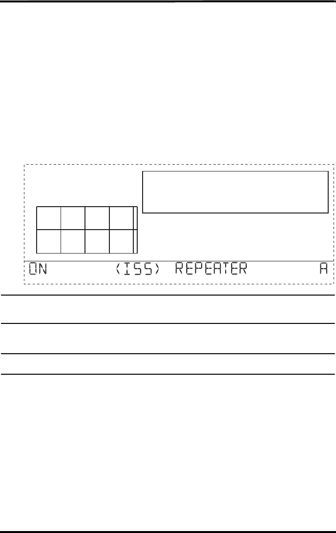
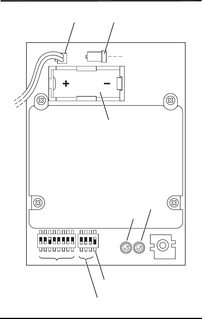
Repeater Board Display and Contents
Transmitter
DIP Switches
Repeater
DIP Switches
Repeater
Test Switch
TX
LED
Status
LED
Battery
Compartment
Solar Power Tab AC Adpater