Daviscomms CYBER80211 802.11b/g VoIP WiFi SIP Phone User Manual manual
Daviscomms (S) Pte Ltd 802.11b/g VoIP WiFi SIP Phone manual
manual

Table of Contents
1: Get started . . . . . . . . . . . . . . . . . . . . . . 3
1. Standard package contents . . . . . . . . . . .3
2. Phone specification . . . . . . . . . . . . . . . . . 3
3. Phone description . . . . . . . . . . . . . . . . . . 4
4. Installing & removing the battery . . . . . . . 5
5. Charging the battery . . . . . . . . . . . . . . . . 6
6. Powering the Cyber phone on & off . . . . 7
7. Display indicators & icons . . . . . . . . . . . . 8
8. Shortcut menu . . . . . . . . . . . . . . . . . . . . . 9
9. Main Menu icons . . . . . . . . . . . . . . . . . . . 10
2: Configuring your phone . . . . . . . . 11
1. Important information you should
know first . . . . . . . . . . . . . . . . . . . . . . . . . 11
2. Connecting your phone to an AP . . . . . . .13
3. Connecting your phone to an SIP . . . . . . 14
3: Basic call functions . . . . . . . . . . . . 15
1. Making a IP to IP call (via direct IP) . . . . .15
2. Making a SIP to SIP call (via SIP server). 16
3. Making a call (via SIP server to landline
or GSM mobile phone) . . . . . . . . . . . . . . 17
4. Speed dial . . . . . . . . . . . . . . . . . . . . . . . . 18
5. Answering a call . . . . . . . . . . . . . . . . . . . 18
6. Mute/Un-mute a call . . . . . . . . . . . . . . . . .18
7. Hold . . . . . . . . . . . . . . . . . . . . . . . . . . . . . 18
4: Menu . . . . . . . . . . . . . . . . . . . . . . . . . . . 20
i Messages . . . . . . . . . . . . . . . . . . . . . . 20
1) Keypad legends. . . . . . . . . . . . . . . . .21
2) Create . . . . . . . . . . . . . . . . . . . . . . . .22
3) Inbox . . . . . . . . . . . . . . . . . . . . . . . . .23
4) Outbox . . . . . . . . . . . . . . . . . . . . . . . 25
5) Chat . . . . . . . . . . . . . . . . . . . . . . . . . 26
ii Contacts . . . . . . . . . . . . . . . . . . . . . . . 27
1) Add . . . . . . . . . . . . . . . . . . . . . . . . . . 28
2) Edit . . . . . . . . . . . . . . . . . . . . . . . . . . 28
3) Delete . . . . . . . . . . . . . . . . . . . . . . . . 29
4) View Entry . . . . . . . . . . . . . . . . . . . . 29
5) Speed Dial . . . . . . . . . . . . . . . . . . . . 29
iii Call Log . . . . . . . . . . . . . . . . . . . . . . . 30
1) Missed calls . . . . . . . . . . . . . . . . . . . 31
2) Incoming calls. . . . . . . . . . . . . . . . . . 31
3) Outgoing calls . . . . . . . . . . . . . . . . . .31
8. New calls . . . . . . . . . . . . . . . . . . . . . . . . . 18
9. Rejecting a call . . . . . . . . . . . . . . . . . . . . 19
10. Silencing the incoming ring tone . . . . . . . 19
11. Call waiting . . . . . . . . . . . . . . . . . . . . . . . 19
12. Conference call . . . . . . . . . . . . . . . . . . . . 19
1

iv Settings . . . . . . . . . . . . . . . . . . . . . . . 32
1) Clock . . . . . . . . . . . . . . . . . . . . 34
2) Wallpaper . . . . . . . . . . . . . . . . . 36
3) Ring tones . . . . . . . . . . . . . . . . 36
4) Message tones . . . . . . . . . . . . . 37
5) Ring Volume . . . . . . . . . . . . . . . 37
6) Receiver volume . . . . . . . . . . . 37
7) Alert mode . . . . . . . . . . . . . . . . 38
8) Message View . . . . . . . . . . . . . 38
9) Brightness . . . . . . . . . . . . . . . . 38
10) Key backlight . . . . . . . . . . . . . 39
11) Auto key lock . . . . . . . . . . . . . . 39
12) Key tone . . . . . . . . . . . . . . . . . 39
13) DTMF tone . . . . . . . . . . . . . . . 39
14) Screen Banner . . . . . . . . . . . . 40
15) Factory reset . . . . . . . . . . . . . . 40
16) Software upgrade . . . . . . . . . . 41
v: Configuration . . . . . . . . . . . . . . . . . . . . . . . 45
1) SIP settings . . . . . . . . . . . . . . . . 46
2) IP settings. . . . . . . . . . . . . . . . . 49
3) WLAN settings . . . . . . . . . . . . . .52
vi: Information . . . . . . . . . . . . . . . . . . . . . . . . 56
1) SIP information . . . . . . . . . . . . . 56
2) IP information . . . . . . . . . . . . . . 56
3) WLAN information. . . . . . . . . . . 56
4) General information . . . . . . . . . 56
5. Web configurator. . . . . . . . . . . . . . 57
6. Glossary . . . . . . . . . . . . . . . . . . . . 67
7. Health and safety information . . . 68
8. FCC Declaration . . . . . . . . . . . . . . .71
2
1. Get Started
1: Standard Package Contents
Please check carefully if you have the items mentioned
below:
1: WiFi Phone x 01
2: USB Charger x 01
3: USB Cable x 01
4. Battery x 01
5. User’s Manual x 01
6. Lanyard Strap
*Actual contents may vary.
2: Phone Specifications
Dimensions: 96(L) x 65(W) x
16(H) Dimension in
mm.
Weight: 65g (without battery)
80g (with battery)
Battery: 650 mAh Li-ion,
3.7v
Charger Input: 100-240v – 50-60Hz
0.2A
Charger Weight: 50g
Charging Time: 3 hours
Standby Time: 48 hours depending
on the network
Talking Time: 2 hours depending
on the network 3
The CYBERPHONE is a 802.11b/g VoIP
WiFi SIP Phone.
Get Started
Get Started
4
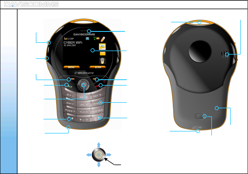
3: Phone Description
Earpiece
OLED screen
Right Soft Key
End / Power key
Number keys
Silent mode
key
Left soft
key
Volume up
key
Volume
down
key
Switch input method
key / keypad lock.
Talk / Call
key
5 Way
joystick
USB Port Battery
cover door
Loop for
Lanyard
Speaker
hole
5-Way Joystick 1
2
34
5 – Push down to select an option
Battery cover
door release
button
Mic
Scroll left for system info In the idle screen, scroll joystick right for shortcut menus
Push up to scroll on the side bar menus
Push down to scroll on the side bar menus
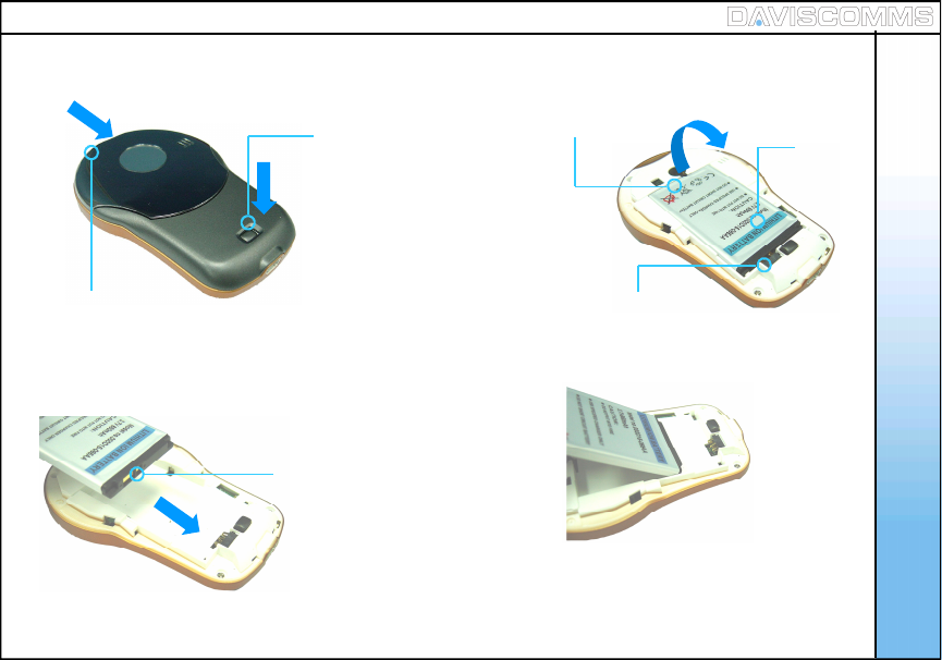
4: Installing and Removing the battery
1. Push and hold the
battery door button down.
2. While the button is
pushed down, push from
the top and slide the
battery door cover outwards.
Battery
Contact point
3. To remove, lift the
battery out
from here
4. To install the battery,
ensure that the contact
points are aligned.
5. Insert the direction shown
in the diagram FIRST.
Re-attach the battery door.
Get Started
*Please refer to page.69 for more information on your battery. 5
Get Started
6
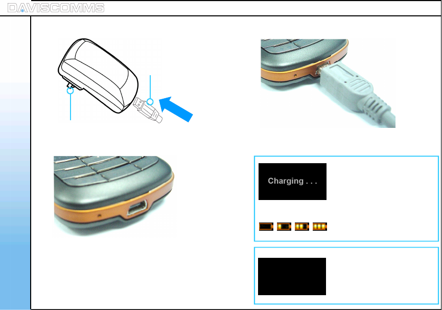
5: Charging the battery
2. Insert the charger into
your wall power outlet.
1. Plug the USB cable into
the charger or to a
computer USB port.
3. Locate the USB port at
the bottom of your phone.
4. Plug the other end of the USB cable in and turn
on the main power to begin charging
With the phone turned
on/off, this Screen will
appear when the phone
is charging.
This screen will appear
when the phone’s battery
charging is completed.
OR
This icon will scroll on the
idle screen if its turned on.
Charging Completed
Note: You need to charge the battery for 8 hours
for its first time use.
Get Started
7
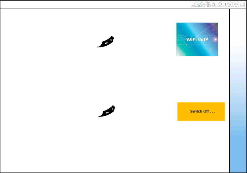
6: Powering the Cyber phone on and off
-To Power ON
Press and hold the (end/off key icon) for 5 seconds, release
and the power up window will be shown.
-To Power OFF
Press and hold the (end/off key icon) for 3 seconds, release
and the power down window will be shown.
Fig.1 Power up window
Fig.2 Power down window
1.0.02
Get Started
8
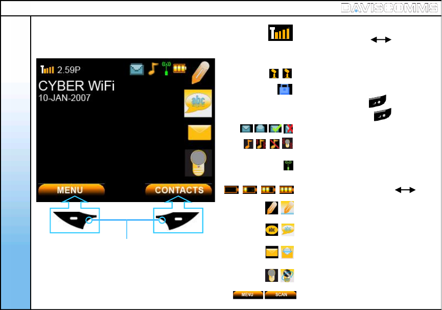
7: Display indicators and icons Received signal strength from WiFi
access point.
Time display
Call mute (Un-mute, Mute)
Keypad lock
Write Message
The roles of the soft keys vary depending on the
function you are using. The keys just below
selects the functions desired when pressed.
NOTE:If you are disconnected from the signal,
the right soft key will automatically change
to the “SCAN” selection.
2.59P
To lock, press and hold for 1 second.
To unlock, press and hold for 1 second.
(Weak Strong)
(Weak Strong)
Message Inbox (new, read, sent, not sent)
Message Icon
Chat Icon
Soft key function indicators
WiFi connectivity status (refer to pg.12)
Alert type (ring, ring and vibrate, silent,
vibrate only)
Battery level indicator
Recent Calls Icon
Idle Screen

Site Scan
SIP Registration
Reload IP
Restart WLAN
Web Configurator
System info provides a summary of the connection details your phone to the network AP.
WLAN :Displays the name of the AP you are connected to.
IP address : Displays the IP address assigned to the phone.
User Name : Displays the User name used for SIP connection.
Proxy Server : Displays the IP address of the proxy server the phone is connected to.
Outbound proxy : Displays the outbound proxy address of the SIP server the phone
is connected to.
8. Shortcut Menu
Shortcut menu allows a quick access to the configuration setting menu of your phone.
System Info
9
BACK
: Allows you to scan and join the list of APs available in your network LAN
: Allows you to activate or reconnect your SIP account on the Cyber WiFi phone
: This function allows you to request an IP address from a DHCP server
: This function restarts the phone’s wireless connection to the AP.
: This function allows you to configure your phone settings using a web browser.
Get Started
Get Started
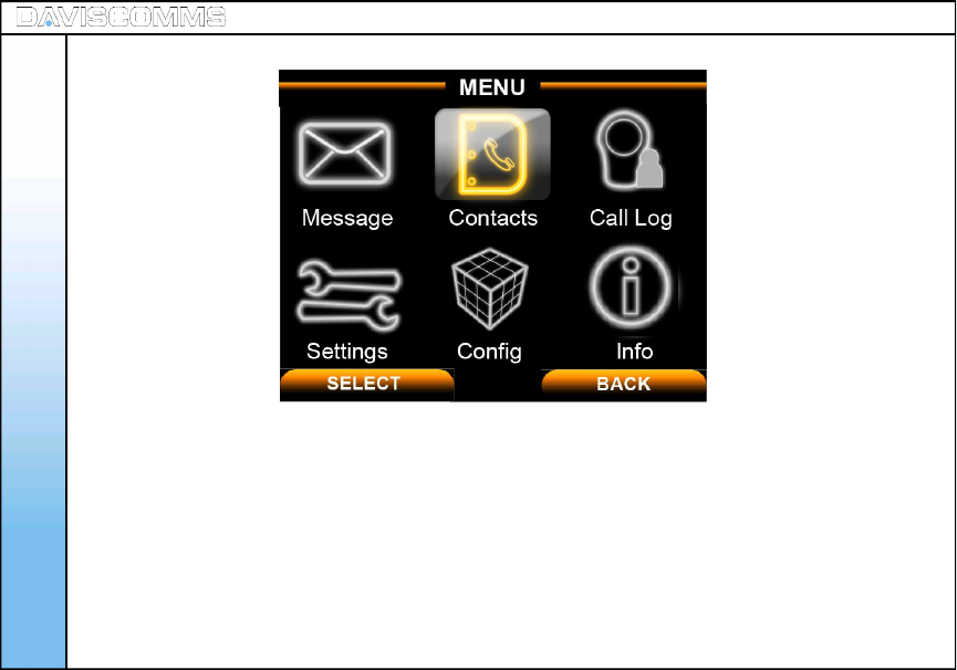
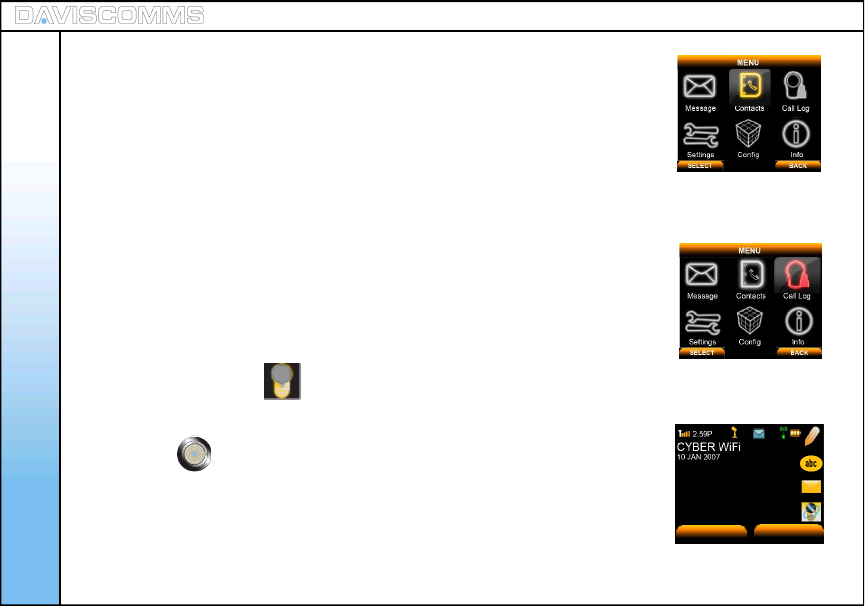
Individual icons will illuminate when selected. Navigate your way around the icons by moving the
joystick. Press the joystick down to select the application.
Message: Use the messages menu to send and receive short messages.
Contacts: Store and find from a list of contacts stored in your contact list.
Call Log: Views the calls you have dialed, received, or missed
Settings: Settings menu provides you with various setting options to customize the phone to your
preferences and needs. You can also reset the setting to their default values.
Config: Use this menu to configure the SIP, IP and WLAN settings.
Info: Use this menu to check the information of your SIP, IP, WLAN and General settings.
10
9: Main Menu Icons

2. Configuring your phone
1: Important information you should know first
-Possible ways of communicating using the CYBERPHONE.
- IP to IP call
- SIP to SIP call
Note: You will need to subscribe with a SIP service provider to make a SIP call.
For reference please refer to www.daviscomms.com.sg
-Requirements in order to establish a communication on the CYBERPHONE.
- The phone must be associated to an AP in order to communicate to other WiFi phones.
Note: - Do take note that there are some network security protocols installed on the LAN which you
wish to connect to.
- Some require registering the MAC address of the CYBERPHONE in order to allow access to
the AP of the network. Under such circumstances, you should seek assistance from your
network administrator to register the MAC address of the phone to the server to gain access to the
network’s AP.
-Encryption
- Connecting the CYBERPHONE to wireless LAN area may require an
encryption password. You will need this password to gain access to the network in order to
associate to the AP you are connecting to.
- Most standard network uses WEP-64 encryption protocol. You would need to consult your network
administrator if the network uses other settings. 11
Configuring Your Phone
12
-SIP Server connection
- A SIP connection allows you to communicate to another SIP user via a WiFi phone without having
the hassle to remember the full length of the IP address number.
Note: - Before you can connect to a SIP server, it is necessary that you obtain a SIP account. You can
also obtain a paid SIP account which provides you communication to a mobile phone number (GSM)
or a landline number (PSTN).
For reference please refer to www.daviscomms.com.sg
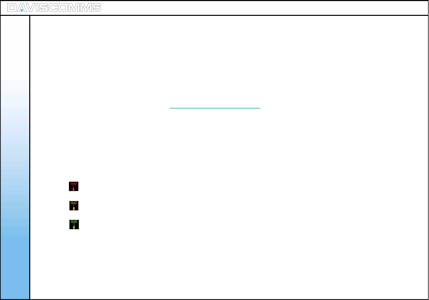
-Connectivity Status
-The connectivity status of your CYBERPHONE must be green in order for your phone to make calls.
Below is the illustration of the connectivity status of your CYBERPHONE.
Configuring Your Phone
Red – Not connected to an AP.
Amber – It is connected to an AP but no IP is being assigned.
Green – Connected to an AP and IP is being assigned.
2: Connecting your phone to an AP
13
Auto Connecting to an AP
Before you proceed to making a call, you will first need the CYBERPHONE to connect to an AP.
Your phone will automatically detect and connect to your pre-configured AP on the first power up.
Manually setting up the phone to connect to an AP in your LAN network
Step.1 - From the idle screen, select > MENU > CONFIG > WLAN > SSID >SCAN within your area, a list
of available AP’s will appear >scroll and select the AP you wish to connect to, select > VIEW
> Select the AP you like to join.
Step.2 - In the same WLAN settings menu, select > ENCRYPTION >
scroll and select > WEP-64. ( Please refer to pg.10, on encryption. )
Step.3 - In the WEP-64 screen, select >OPEN SYSTEM> ( Please confirm this
setting with your Network Administrator. ) and select > KEY 1.
Step.4 - Input the password encryption of the AP set by your network administrator >when done, select >
OK > in the WLAN Settings menu, select ACTIVATE by pressing the left soft key .
Note:-
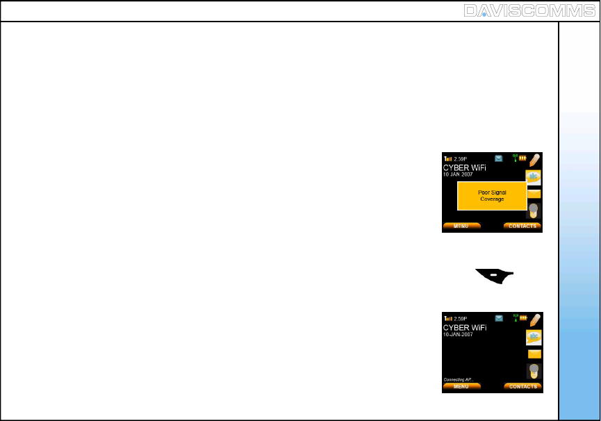
1.) Wait for the connectivity status bar to turn green. The main screen will display “Connecting AP….
” followed by “Connecting IP….” to complete the connection the to the network If the connecting AP disappears
and connectivity is still red, retry. If you still have problems, consult your IT administrator for the network details.
2.) Incase of WEAK SIGNAL, there will be an alert tone & display showing
Step.5 – Once your phone connectivity status turns green
You should be able to make a call via direct IP to IP.
Configuring Your Phone
Fig.4 Calling Screen
Fig.3 Poor Signal Coverage
Screen

3: Connecting your phone to an SIP
OPTIONS HANDFREE
14
Note: - Before you proceed to making a call, you will first need to set up the CYBERPHONE to
register to a SIP server connection.
For reference please refer to www.daviscomms.com.sg
Step.1 - From the idle screen, select > MENU > CONFIG > SIP > USER NAME > input your user name
according to your SIP account details and select > OK.
Step.2 - In the same SIP settings menu, select > PASSWORD > input your password according to your
SIP account details and select > OK.
Step.3 - In the same SIP settings menu, select > PROXY SERVER > IP ADDRESS > key in the address
of your SIP server, for example, > SIPprovider.org and select > OK.
Step.4 - In the Proxy Server settings menu, select > STATUS > and select > ENABLE.
Step.5 - Go back to the SIP settings menu, select > OUTBOUND PROXY > IP ADDRESS > key in the
IP address of your SIP server, for example, > SIPprovider.org and select > OK.
Step.6 - In the Outbound Proxy settings menu, select > STATUS > and select > ENABLE.
Step.7 - Go back to the SIP settings menu, select > ACTIVATE by pressing the left soft key .
Note: - After activating, a “Registering SIP…” display will be appear at the Idle screen.
The “Not Registered” sign will disappear on the idle screen to indicate that your
CYBERPHONE is connected to your SIP server account.
Step.8 - You are now ready to make a SIP to SIP call via SIP server.
Configuring Your Phone
Basic Call Functions
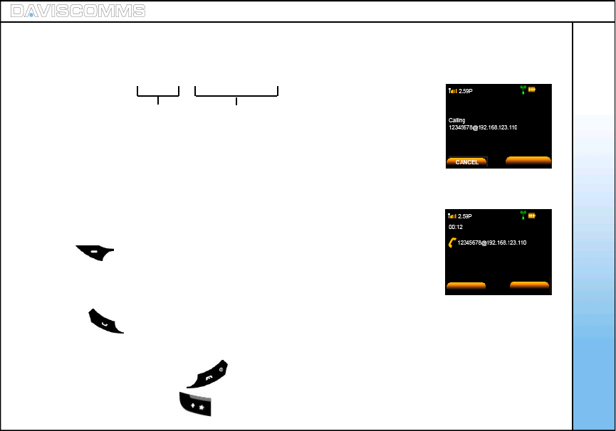
For eg:- 1234567@191.166.123.203
Note: Please make sure to disable the SIP settings before making an IP to IP
call. To do so, please follow the steps below:
Disabling SIP - Go to MENU > CONFIG > SIP > PROXY SERVER > STATUS >
select DISABLE > select BACK > OUTBOUND PROXY > STATUS >
select DISABLE > select BACK > ACTIVATE by pressing the left soft
key .
Step.1 - In the idle screen, key in the number, for eg:-
1234567@191.166.123.203
Step.2 - Press and “calling 1234567@191.166.123.203” will be displayed.
Step.3 - When the call is connected, call timer will be displayed.
Step.4 - To end the call, press the key.
Note: “@” is keyed by pressing key twice.
Fig.5 Calling Screen
Fig.6 Call timer screen
These figures are defined
by the recipient’s user name
In the SIP settings.
These figures refers to recipients
FIXED IP number
OPTIONS
15
3. Basic Call Functions
1: Making an IP to IP call (via direct IP)
SPEAKER
SPEAKER
Basic Call Functions
OPTIONS HANDFREE
For eg:- 31080240
Step.1 - Key in the SIP contact number
Step.2 - Press and “calling 31080240 will be displayed.
Step.3 - When the call is connected, call timer will be displayed.
Step.4 - To end the call, press the key.
These figures will be the other parties SIP
phone number you wish to dial.
16
Note: A user can only call to the other party via the same SIP provider. Please refer to your SIP
provider’s agreement if you are contacting another person of another SIP provider account.
Do make sure that your SIP settings are activated. (Refer to Pg.14)
2: Making a SIP to SIP call (via SIP server)
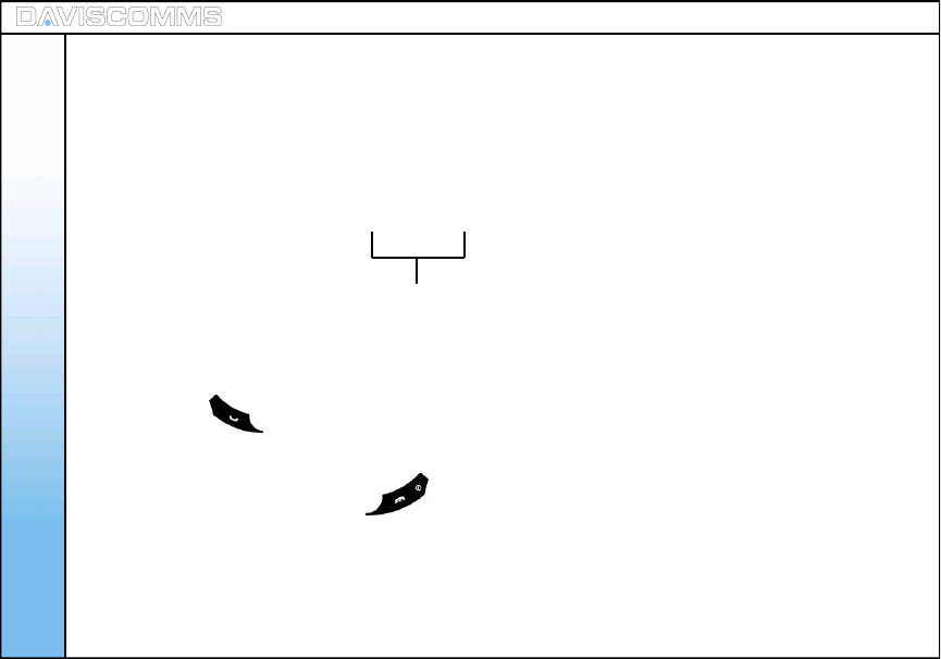
3: Making a call ( via SIP server to Landline / GSM Mobile Phone)
Basic Call Functions
Note: For eg:- 65 62100123
Step.1 - Key in the number, for eg:- 6562100123
Step.2 - Press and “calling 6562100123” will be displayed.
Step.3 - When the call is connected, call timer will be displayed.
Step.4 - To end the call, press the key.
Country code Land line number
or mobile number
Note: You can only call a Landline / GSM Mobile phone line depending on your SIP Server account
services.
For reference please refer to www.daviscomms.com.sg
Do make sure that your SIP settings are activated. (Refer to Pg.14)
17
4: Speed dial
5: Answering a call
6: Mute/Un-mute a Call
7: Hold
8: New Calls
- Refer to page.29 for the setting up of speed dial.
- During standby mode, press and hold the preset key for 1 second to display
the name and phone number, press left soft key to call.
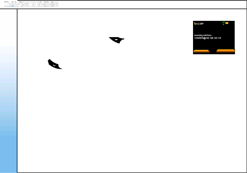
- Press the key to answer incoming calls. Call timer will be displayed.
Basic Call Functions
SILENT
Fig.7 Incoming call screen
18
- During a call is answered, click on options> scroll to mute and click select.
To un-mute the call, click on options> scroll to mute and click select.
During a call you can put the other party to hold by clicking on options> scroll to Hold and click select.
New calls allows you to connect to another user while having one conversations active at the same time.
To create a new call, click on options during a call> scroll to New call > click select> Key in number or
select Contacts> click Call
SPEAKER
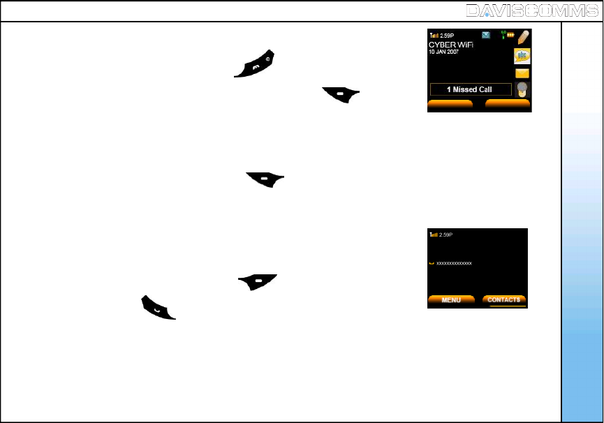
- When there is an incoming call, press the key to reject the call.
- Number of missed calls will be displayed. Press the left soft key to
view the missed call.
9: Rejecting a call
10: Silencing the incoming ring tone
11: Call waiting
12: Conference Call
Fig.8 Missed call screen
- When there is a incoming call, press the left soft key >select SILENT.
Fig.9 Hold call screen
- When another call comes in during a call, it will give a waiting tone.
- To reject the incoming call, press the left soft key >select REJECT.
- To answer, press the .
Basic Call Functions
VIEW EXIT
19
During a call, click on OPTIONS during a call >scroll to NEW CALL > click SELECT >
key in a phone number or select CONTACTS > click CALL > when third party answers,
click OPTIONS > and select a phone number.
Menu - Message
20
4. Menu
Menu – ( i ) Messages
Create Allows you to create messages and send it to another party.
Inbox and Outbox Allows to you view, edit and delete the messages.
- Read Allows you to read the messages.
- Reply Allows you to reply the messages you read.
- Forward Allows you to forward the message you read to another party.
- Delete Allows you to delete the message you select.
- Delete All Allows you to delete all messages.
Chat Allows you to create a chat session with another recipient.
Menu - Message
21
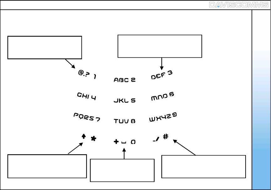
( 1 ) Keypad Legends
Press once to change between
ABC (uppercase), abc (lowercase)
and 123 (numeric)
Press repeatedly to scroll
through various punctuations.
Press once for SPACE
and LONG PRESS
for “+”
Press repeatedly to scroll
between ( . @ : )
Hold to display the symbol table
Press repeatedly to scroll through
the corresponding letters.
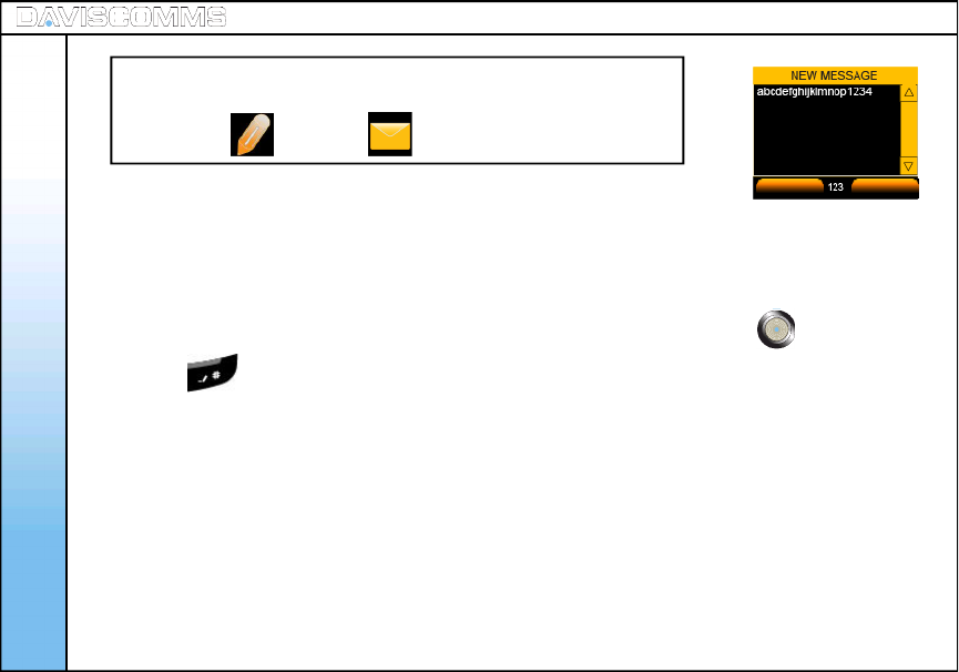
( 2 ) Create
- Select MENU > MESSAGES > CREATE > type the message >select OK >
key in a phone number and select > OK. OR select CONTACTS to pick an
existing contact in your phonebook and send.
Note: You can also select MESSAGES from the idle screen by scrolling up or
down with the joystick and selecting it by pressing the center of the joystick.
Press the key to switch the text mode between “ABC”, “abc” and “123”.
- ABC – Uppercase
- abc – Lowercase
- 123 – Numeric
Menu - Message
Fig.10 Write Message Screen
OK BACK
Tip:
You can create new messages or check your message inbox by
selecting the icon or the icon at the idle screen.
22
( 3 ) Inbox
Inbox: Read
Inbox: Reply
Inbox: Forward
- Select MENU > MESSAGE > INBOX.
Note: You will be notified if there is a new message in your inbox from the idle screen
by spotting the icon at the top of the idle screen.
Note: Messages in the Inbox can be viewed. The arrangement of messages is
latest (TOP) to earliest (BOTTOM)
These are the following menus found when you access the INBOX.
- From the MESSAGES menu >Select INBOX >Select the message you want to
read >press the center of the joystick to open the message to read.
- From the MESSAGES menu >select INBOX>select the message you want to
reply > OPTIONS > REPLY.
- From the MESSAGES menu >select INBOX>select the message you want to
forward > OPTIONS > FORWARD.
Menu - Message
YES NO
23
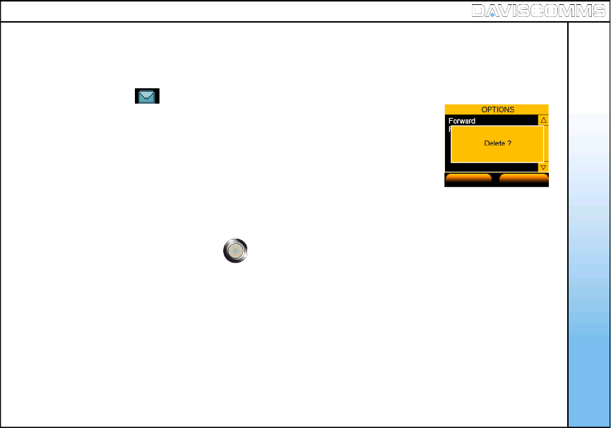
Fig.11 Delete Message Screen
Menu - Message
Inbox: Delete
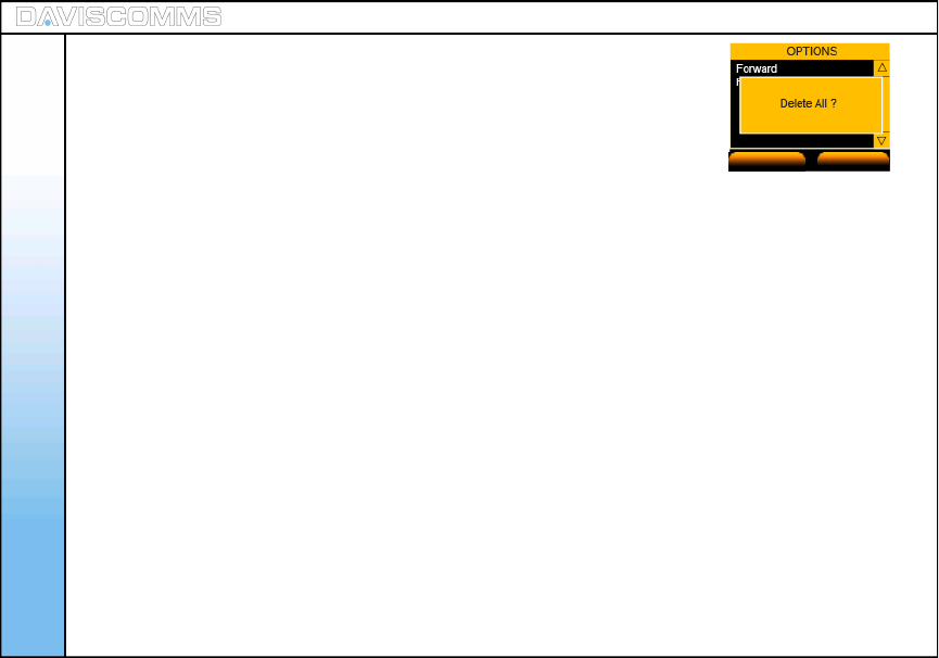
Inbox: Delete All
- From the MESSAGES menu >select INBOX>select the message you
want to delete > OPTIONS > DELETE > select YES to confirm or NO to
cancel.
- From the MESSAGES menu >select INBOX > OPTIONS > DELETE ALL
>select YES to confirm or NO to cancel.
Note: All messages will be deleted permanently.
YES NO
Fig.12 Delete All Message Screen
24

Menu - Message
( 4 ) Outbox
Outbox: Read
Outbox: Forward
Outbox: Delete
Outbox: Delete All
- Select MENU > MESSAGE > OUTBOX >
Note: Messages in the Inbox can be viewed. The arrangement of messages is
latest (TOP) to earliest (BOTTOM).
- From the MESSAGES menu >Select OUTBOX >Select the message you
want to read >press the center of the joystick to read the message.
- From the MESSAGES menu >select OUTBOX > select the message you
want to forward > OPTIONS > FORWARD.
- From the MESSAGES menu >select OUTBOX > select the message you want to
delete > OPTIONS > DELETE > select YES to confirm or NO to cancel.
- From the MESSAGES menu >select OUTBOX > OPTIONS >
DELETE ALL > select YES to confirm or NO to cancel.
Note: All messages will be deleted permanently.
Fig.13 Delete Message Screen
Fig.14 Delete All Message Screen
YES NO
YES NO
25
( 5 ) Chat
Note: The chat session can function on a IP to IP connection
or a SIP to SIP connection.
Please check with your SIP provider if their service support
messaging capability.
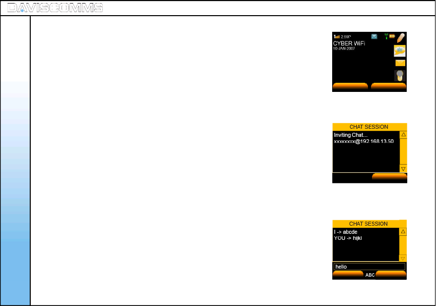
- Select MENU > MESSAGES > CHAT
- Enter the phone number of the recipient which you want the CHAT
session to be associated with.
- Contacts can be retrieved from the phonebook. Select OK.
- For e.g:- INVITING 12345678 @ xxx.xxx.xxx.xxx will be displayed
in the screen.
- Once the chat request has been accepted by the recipient, chat session
can take place.
Note: “YOU” Indicates the message you have received.
“ I “ indicated the message you have sent.
Menu - Message
Fig.15 Banner Screen - Chat
MENU CONTACTS
26
CANCEL
Fig.16 Chat Session Invitation Screen
Fig.17 Chat Screen
SEND CLEAR
Menu - Contacts
27
Add Allows you to add a new contact into your contact list.
Edit Allows to you edit the contact which is stored in your contact list.
Delete Allows you to delete a contact permanently from your contact list.
Speed Dial Allows you to set a particular contact to a numeric key on your keypad.
Adding a Contact
from Idle Screen Allows you to add a new contact directly from the idle screen.
Menu – ( ii ) Contacts
( 1 ) Add
( 2 ) Edit
To add from Contacts:
- Select MENU > CONTACTS > OPTION > ADD > ( Input name ) > OK
( Input Phone Number ) > OK.
To add from Call Log:
- Select Call Log > select either Missed Calls,Incoming Calls or Outgoing Calls
>highlight the number, select OPTION > SAVE > ( Enter name ) > APPLY.
To add from Idle Screen:
From the idle screen, key in the number of the CONTACT > click SAVE > Input the
name of the Contact > Click OK once done.
Note: “Replace existing entry?” will be displayed if there is an existing contact.
Note: You can also select Recent Calls from the idle screen by scrolling
up or down with the joystick and selecting it by pressing the center of the
joystick .
- Select CONTACTS > select the person you want to edit > OPTION > EDIT >
enter name > OK>enter number > OK. to confirm.
Fig.18 CONTACT Selected
Fig.19 CALL LOG Selected
Fig.20 Idle Screen – Call Log
MENU CONTACTS
28
Menu - Contacts
( 3 ) Delete
( 4 ) View Entry
( 5 ) Speed Dial
- Select CONTACTS > select the person you want to delete > OPTION > DELETE > select YES to
delete or NO to cancel.
- Select CONTACT > select a contact from the list > push joystick button down to VIEW.
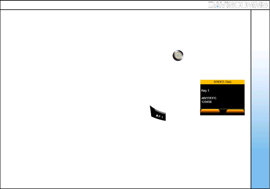
- Select CONTACTS > select a contact from the list > OPTION >SPEED DIAL
>SET.
- To Unset, scroll to the Key number and press UNSET.
- If you have a contact under key.1, in the idle screen, hold the key and it
will dial the contact which you have assigned it with. Fig.21 Speed Dial Screen
SET BACK
29
Menu - Contacts
Menu – Call Log
30
Missed Calls
Incoming Calls
Outgoing Calls
Menu – ( iii ) Call Log
Recent Calls
Shows you the list of the numbers you have called, received or
missed picking up their call. Selecting the particular contact allows
you to save the particular contact in your list, delete or delete all
contacts.
Shows you the summary list of the your outgoing, answered
or missed calls.
Recent Calls
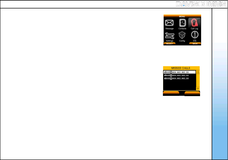
- Select MENU > CALL LOG > MISSED CALLS.
To Save, Delete or Delete All, select an entry and select OPTIONS.
Note: Missed call list will appear from latest (top) to earliest (bottom).
- Select MENU > CALL LOG > INCOMING CALLS.
To Save, Delete or Delete All, select an entry and select OPTIONS.
Note: Incoming call list will appear from latest (top) to earliest (bottom).
Menu – Call Log
( 1 ) Missed Calls
( 2 ) Incoming Calls
Fig.22 Call Log Selected
Fig.23 Missed Call Screen
OPTION BACK
31
( 3 ) Outgoing Calls
- Select MENU > CALL LOG > OUTGOING CALLS.
To Save, Delete or Delete All, select an entry and select OPTIONS.
Note: Outgoing call list will appear from latest (top) to earliest (bottom).
Menu - Settings
32
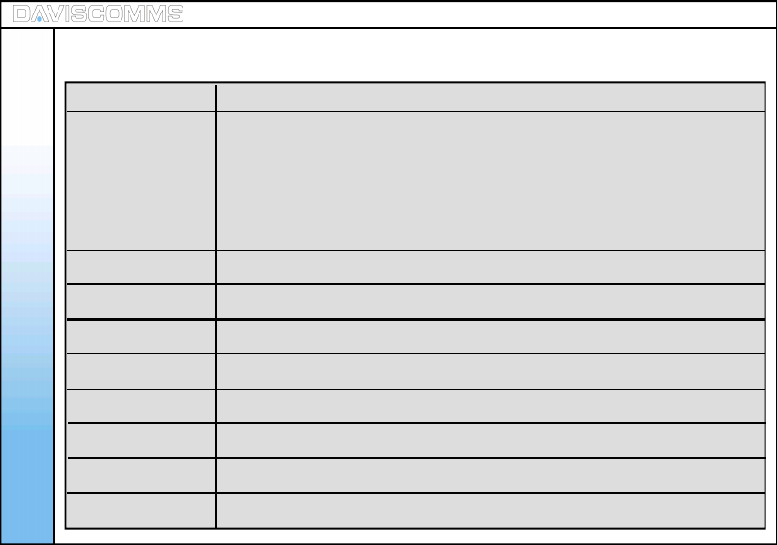
Clock Allows you change the time, date and its formats.
- Set Time Allows you to set the time which will be displayed on the idle screen
- Set Date Allows you to set the date which will be displayed on the idle screen.
- Time Format Allow you to set the time format to be 12 or 24 hours.
- Date Format Allows you to set the date format to DD/MM/YY or MM/DD/YY.
Wallpaper Allows you to change the wallpaper in the idle screen.
Ring Tones Allows you to change the incoming call ring tones.
Message Tones Allows you to change the alert tones for incoming messages.
Ring Volume Allows you to set the ring volume from low to high.
Receiver volume Allows you to set the volume of your receiver from low to high.
Alert Mode Allows you to set your alert to Silent, Vibrate, Melody and Melody and Vibrate.
Message View Allows you to view message list based on contacts or message itself
Brightness Allows you to view message list based on contacts or message itself
Menu – ( iv ) Settings
33
Menu - Settings
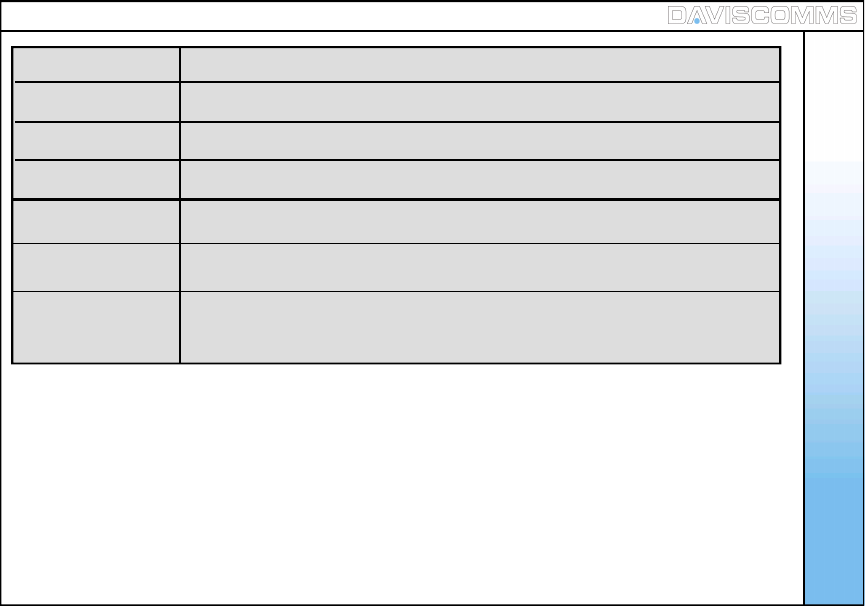
Key Backlight Allows you to set the keypad light to stay Off, after 10, 20 or 30 seconds.
Auto Key Lock Allows you set the Auto Key Lock feature to off, 30secs, 1min and 2mins.
Key Tone Allows you turn the key tone On or Off when the keys are pressed.
DTMF Tone Allows you to set the DTMF tone to inbound or outbound.
Screen Banner Allows you to type in a banner message in the idle screen.
Factory Reset Allows you to set the entire phone back to its original factory settings. The
phone will power off automatically.
Software upgrade: Allows you to update the phone’s software of the phone to optimize its
performance
Menu - Settings
34
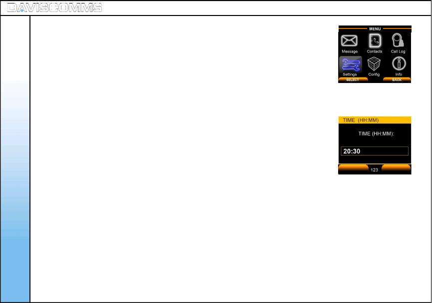
Format: HH/MM = HOUR/MINUTE
- Select MENU > SETTINGS > CLOCK > SET TIME > key in the current
time.
Fig.25 Time Setting Screen
( 1 ) Clock
Clock: Set Time
Fig.24 Setting Selected
OK BACK
Menu - Settings
35
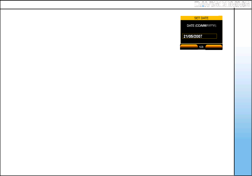
Format: DD/MM/YYYY = DAY / MONTH / YEAR
- Select MENU > SETTINGS > CLOCK > SET DATE and key in the current
date
Fig.26 Date Setting Screen
Clock: Set Date
OK BACK
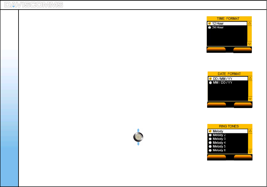
- Select MENU > SETTINGS > CLOCK > TIME FORMAT > select either
12 Hour or 24 Hour and choose SELECT.
- Select MENU > SETTINGS > CLOCK > DATE FORMAT >select either
DD / MM / YY or MM / DD / YY and choose SELECT.
- Select MENU > SETTINGS > WALLPAPER > select the wallpapers of your
preference by scrolling the joystick in any direction, and choose SELECT.
- Select MENU > SETTINGS > RING TONES > select the ring tone of your
preference by scrolling the joystick up or down , a preview of the ring
tone you choose will be played. Choose SELECT to set.
Fig.27 Time Format Setting Screen
Clock: Time Format
Clock: Date Format
( 2 ) Wallpaper
( 3 ) Ring Tones Fig.28 Date Format Setting Screen
Fig.29 Ring Tone Setting Screen
SELECT BACK
SELECT BACK
SELECT BACK
Menu - Settings
36
Menu - Settings
37
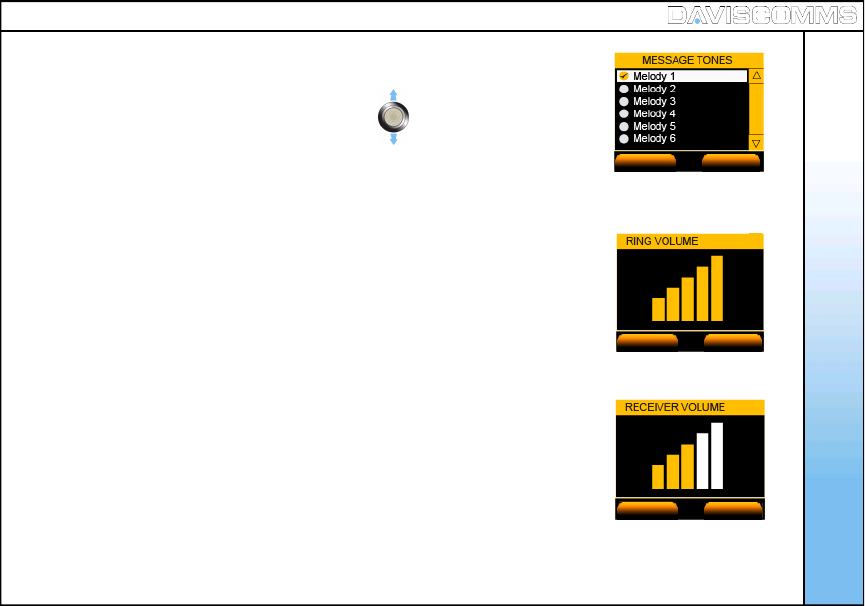
- Select MENU > SETTINGS > MESSAGE TONES > select the ring tone of your
preference by scrolling the joystick up or down , a preview of the message
tone you choose will be played. Choose SELECT to set.
- Select MENU > SETTINGS > RING VOLUME > increase or decrease the
volume by scrolling either direction of the joystick >choose SELECT to set.
- Select MENU > SETTINGS > RECEIVER VOLUME > increase or decrease the
volume by scrolling either direction of the joystick >choose SELECT to set.
Fig.30 Message Tone Setting Screen
( 4 ) Message Tones
( 5 ) Ring Volume
( 6 ) Receiver Volume
Fig.31 Ring Volume Setting Screen
Fig.32 Receiver Volume Setting Screen
SELECT BACK
SELECT BACK
SELECT BACK
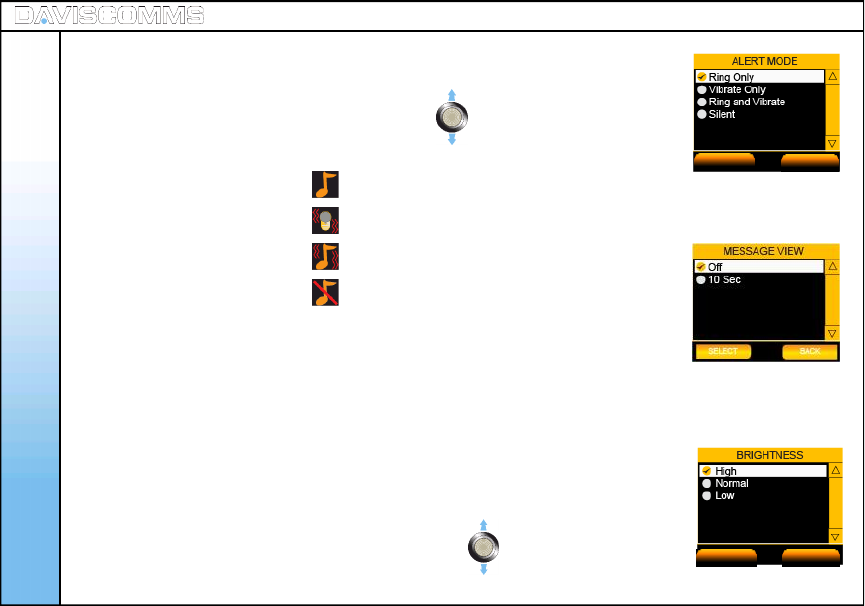
- Select MENU > SETTINGS > ALERT MODE > select the alert mode of your
preference by scrolling the joystick up or down , choose SELECT to set.
Note: The following alert icons will appear on the idle screen depending on your selection.
Ring Only:
Vibrate Only:
Ring and Vibrate:
Silent:
- Select MENU > SETTINGS > MESSAGE VIEW > to view message through
Search name or Message itself. choose SELECT to set.
- Select MENU > SETTINGS > BRIGHTNESS > select the intensity of
your preference by scrolling the joystick up or down ,
choose SELECT to set.
Fig.33 Alert Mode Setting Screen
( 7 ) Alert Mode
( 8 ) Message View
( 9 ) Brightness
Fig.35 Key Backlight Setting Screen
SELECT BACK
SELECT BACK
Menu - Settings
38
Fig.34 Message View Screen
Menu - Settings
39
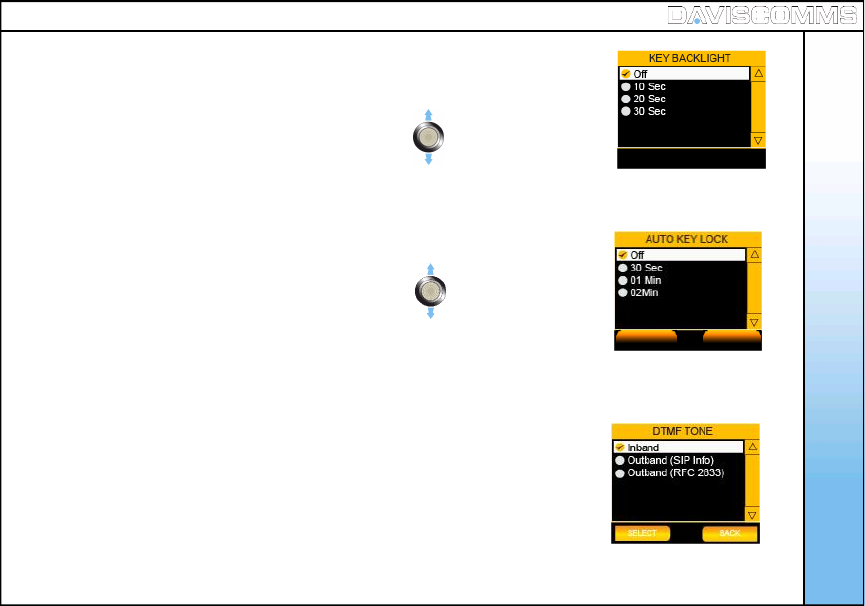
- Select MENU > SETTINGS > KEY BACKLIGHT > select the backlight timer of
your preference by scrolling the joystick up or down , choose SELECT
to set.
- Select MENU > SETTINGS > AUTO KEY LOCK > select the key lock timer of
your preference by scrolling the joystick up or down .
Choose SELECT to set.
- Select MENU > SETTINGS > KEY TONE > select ON or OFF>
choose SELECT to set.
-Select MENU > SETTINGS > DTMF TONE > select INBAND,
OUTBAND (Sip Info) or OUTBAND (RFC 2833) >choose SELECT to set.
Note: DTMF (Dual Tone Multiple Frequency)
Fig.37 Key Lock Setting Screen
( 10 ) Key Backlight
( 11 ) Auto Key Lock
( 12 ) Key Tone
( 13 ) DTMF Tone
SELECT BACK
Fig.36 Key Backlight Setting Screen
Fig.38 DTMF tone setting
Menu - Settings
40
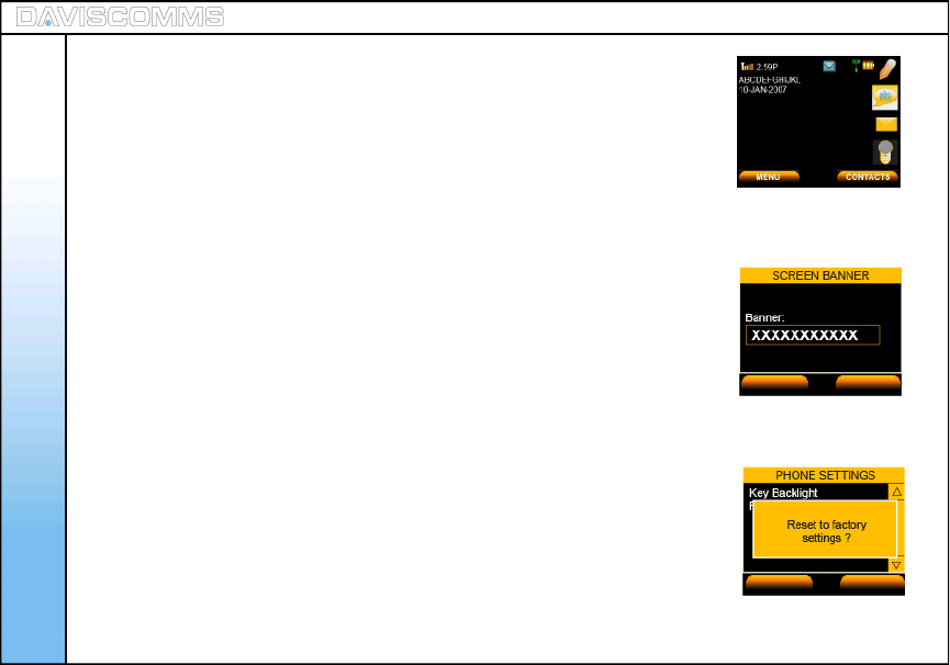
- Select MENU > SETTINGS > SCREEN BANNER > key in your message,
>choose OK to set.
Note: You can input up to a maximum of 12 Characters.
- Select MENU > SETTINGS > FACTORY RESET > choose YES to reset,
or NO to cancel.
Note: The phone will reboot and turn off.
Fig.40 Banner Message
( 14 ) Screen Banner
( 15 ) Factory Reset
Fig.41 Factory Reset Screen
APPLY CLEAR
OK BACK
Fig.39 Banner Message at Idle Screen

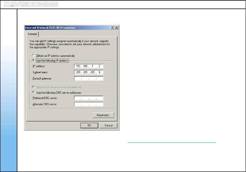
Note: During the Software upgrading, in your computer, make sure that under CONTROL PANEL >
NETWORK CONNECTION, the Local Area Connection of the CYBERPHONE is present.
Please also take note of the IP address at the startup screen You should only start your
TFTP program after this.
Important: Do not disconnect the phone from the PC while it is in firmware upgrading progress.
Doing so will permanently damage the phone.
- To upgrade to the latest software, key in the service provider’s IP address and
the software will be upgraded. To do so:
Step:1 - Insert USB cable to the phone
Step:2 - In the CYBERPHONE, go to > MENU > SETTINGS > SOFTWARE UPGRADE > TFTP SERVER >
key in the IP address for e.g:- > 192.168.1.2 > OK > windows XP should prompt you for installation
of the USB driver.
Note: The IP address you enter in the TFTP server is the address where you wish to download the
image file from.
Step:3 - Install the driver using “athenac902.sys” which is provided on the DAVISCOMMS website at:
www.daviscomms.com.sg
Step:4 - In your computer, under CONTROL PANEL > NETWORK CONNECTIONS, a new
Local Area Connection should appear.
Menu - Settings
( 16 ) Software Upgrade
Software Upgrade - TFTP Server
41
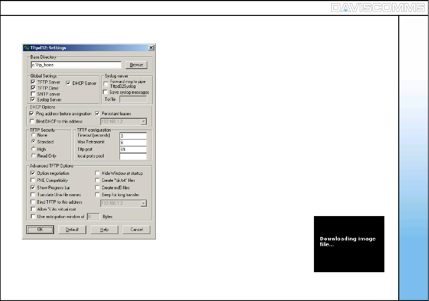
Step:8 - On the CYBERPHONE, in the FIRMWARE UPGRADE menu, choose
the appropriate software part (upgrade firmware, upgrade web config
or upgrade bootloader) you want to upgrade. Once you choose an option,
the phone will start to download the file.
Menu - Settings
43
Fig.42 Image Downloading Screen
Step:7 - After installation, set the settings of the TFTP program to be:
Menu - Settings
44
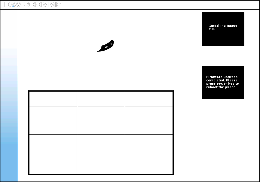
Step:9 - After downloading the file, the phone will install the required file.
Step:10 - When the phone has successfully installed the file, the phone will
display a screen to inform you that the firmware upgrade is completed.
Step:11 - Press and hold the Power key for 3 seconds and release. The
new firmware should have been installed.
Note: If there is an error during the firmware upgrading, an error screen will
appear. If the error screen appears at Step 8, shut down the phone
and restart it, then, go through the entire steps again.
Fig.43 Image Installing Screen
Fig.44 Upgrade Completed Screen
Upgrading
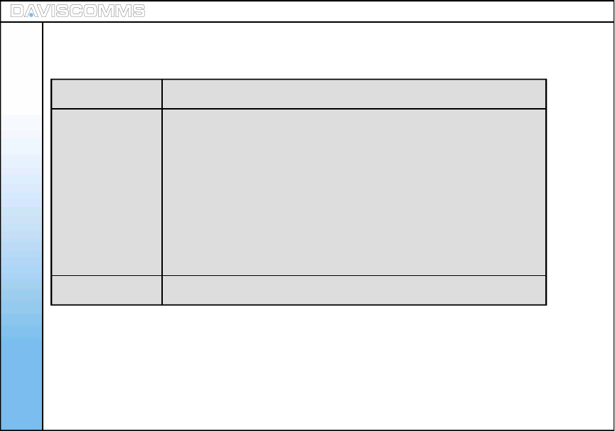
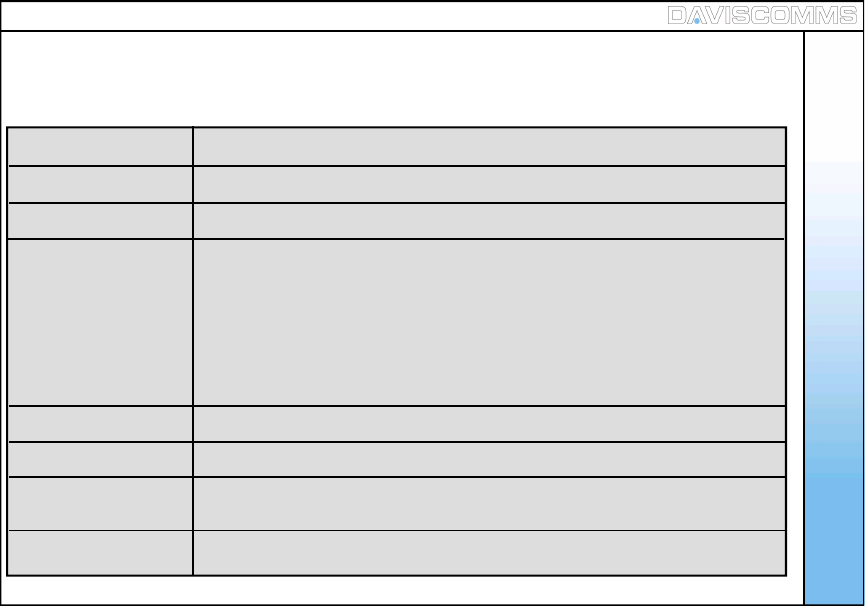
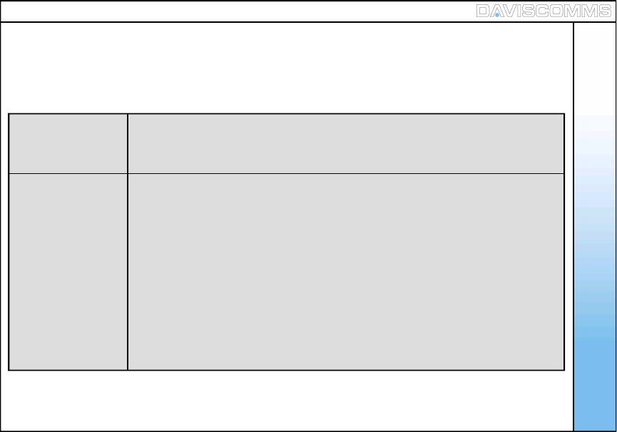
section Error responses
from phone Steps to proceed
Firmware
Upgrade, Web
config and Boot
loader
Error! Please
press power key
to reboot the
phone.
Press power key
to shut down the
phone and repeat
steps
Firmware
Upgrade, Web
config and Boot
loader
Checksum Error!
Please send the
phone for
servicing.
Firmware has
been corrupted.
Send to service
centre for
technical
assistance. Fig.43 Phone Error Response Table
Menu - Configuration
45
Display Name Allows you to key in the user name for display purposes.
User Name Allows you to key in the user name of you SIP account.
Passwords Allows you to key in the password of your SIP account.
Proxy Server Allows you to request a server which services the requests of its clients by
making requests to other servers.
- IP Address Allows you to key in the IP Address of your SIP provider.
- Status Allows you to enable or disable the proxy server
- Registration Time Allows you to key in a time for the proxy server to re-register itself again.
Outbound Proxy Allow you to make/receive call when the phone is behind NAT firewall.
STUN Server Allow you to make/receive call when the phone is behind NAT firewall.
SIP Keep Alive Allow you to maintain SIP server connection when the phone
is behind NAT firewall.
Audio Codec Allows you to select the preferred codec to be used for the call session
Menu – ( v ) Configuration
The Session Initiation Protocol (SIP) is an application-layer control (signaling) protocol for creating,
modifying, and terminating sessions with one or more participants.
Note: You have to configure both SIP Proxy Server settings and Outbound Proxy
server settings. Please refer to your SIP service provider for your account
details. For reference please refer to www.daviscomms.com.sg
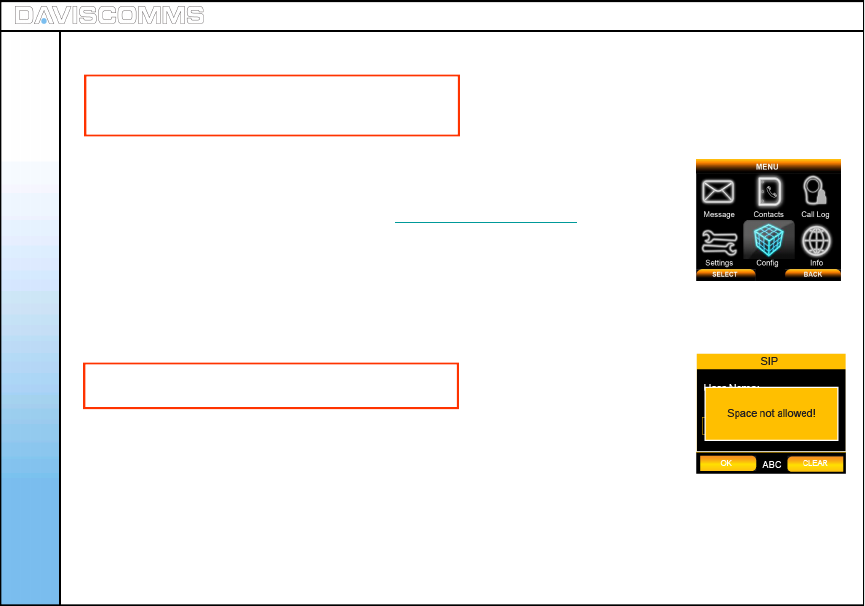
Step.1 - Select MENU > CONFIG > SIP SETTINGS > DISPLAY NAME > for eg:-
key in User > select OK.
Step.2 - In the same SIP settings menu, select > USER NAME > for eg:-
key in Cyber > select OK.
Note: Space are NOT allowed in USER NAME
Step.3 - In the same SIP settings menu, select > PASSWORDS > for eg:- key in
XXXXXXXX > select OK.
Step.4 - In the same SIP settings menu > PROXY SERVER > IP ADDRESS >
for eg:- key in 202.155.130.68 > select OK.
Menu - Configuration
( 1 ) SIP Settings
Fig.45 Config Selected
Note: To change the settings, press the center
of the joystick. To activate, press the left soft key.
46
Fig.46 Spacing Error Screen
Menu - Configuration
Step.5 - In the Proxy Server menu > STATUS > select ENABLE.
Step.6 – In Proxy Server menu > REGISTRATION TIME > for eg:-
key in 3600 > select OK.
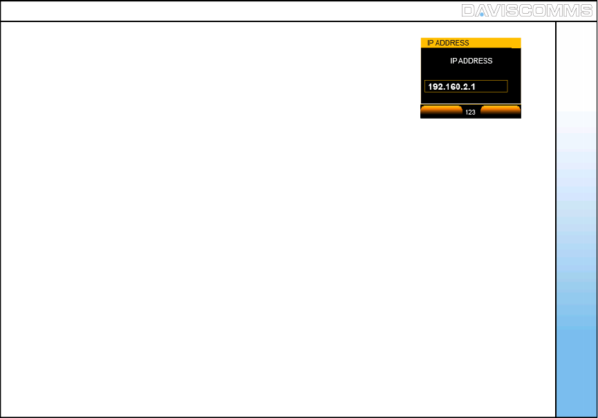
Step.7 - In the same SIP settings menu > OUTBOUND PROXY > IP ADDRESS >
for eg:- key in 192.168.2.1 > select OK.
Note: The outbound proxy server is the address and port that your phone uses to connect to a SIP
server, where there may be NAT routers that do not support the SIP protocol. If your SIP Service
Provider gave you an outbound proxy server address and port, then enter them here.
Step.8 - In OUTBOUND PROXY menu > STATUS > for eg:-
choose ENABLE and select it.
Note: This has to be enabled in order to make a SIP call.
Step.9 - In the same SIP settings menu > STUN SERVER > IP ADDRESS >
for eg:- key in stun.fwdnett.net > select OK.
Step.10 - In the STUN SERVER menu > STATUS > for eg:- choose ENABLE
and select it.
Fig.47 IP Address Screen
APPLY CLEAR
47
Menu - Configuration
Step.11 - In the same SIP settings menu > SIP KEEP ALIVE >
Key in the SIP KEEP ALIVE time for eg:- 20Seconds
and choose ENABLE and select it.
Note: This is to overcome the NAT barrier so that the phone is
contactable by a previously contacted external party.
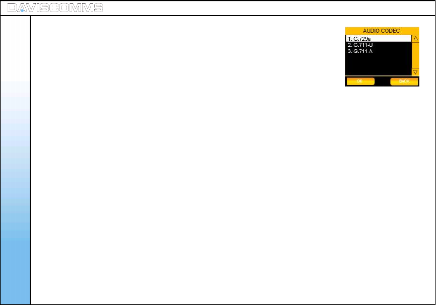
Step.12 - Return to SIP SETTINGS menu >AUDIO CODEC > for eg:-
choose G711-A and select it.
Step.13 – After the configuration, select > ACTIVATE.
Note: This is a program capable of performing encoding
and decoding a voice package.
Note: STUN = Simple Transversal of UDP (User Datagram Protocol)
through NATs (Network Address Translators).
TIP: Enter either the IP address of your SIP server or the URL domain name as given to you by your
Internet Telephony Service Provider.
Fig.48 Audio Codec Screen
48
Menu - Configuration
49
( 2 ) IP Settings
Internet Protocol (IP) is a data-oriented protocol used for communicating data across a
packet-switched network.
DHCP DHCP ( Dynamic Host Control Protocol ) is a set of rules used by communications
devices such as a computer, router or network adapter to allow the device to
request and obtain an IP address from a server which has a list of addresses
available for assignment.
Fixed IP Setup
- IP Address Allows you to key in your fixed IP Address of a network.
- Subnet Mask Allows you to key in an address code which determines the size of the network.
- Default Gateway Allows you to key in an address which forwards internet traffic from your local
area network.
- Primary DNS Allows you to key in the IP Address of your DNS, which can be obtained from
your network administrator.
- Secondary DNS Allows you to key in a secondary DNS.
Menu - Configuration
Step.1 - Select MENU >CONFIG >IP SETTINGS >DHCP > select ENABLE.
Note: With this option you have to manually enter an IP address, subnet mask
and gateway IP address. These are given to you by the network
administrator.
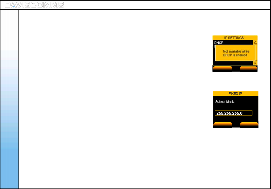
Follow the procedure below to do this.Only when the DHCP
is disabled, can the IP option be available.“Not available while DHCP
is enabled” will be displayed if DHCP is enabled.
Step.1 - Select MENU > CONFIG > IP SETTINGS > DHCP > select DISABLE.
Step.2 - In IP SETTINGS menu > FIXED IP SETUP > IP ADDRESS > for eg:-
key in 192.168.123.204 > select OK.
Step.3 - In FIXED IP SETUP menu > SUBNET MASK > for eg:-
key in 255.255.255.0 > select OK.
Step.4 - In FIXED IP menu > DEFAULT GATEWAY > for eg:-
key in 192.168.123.254 > select OK.
( 2 ) IP Settings
Fig.49 DHCP Notice Screen
Fig.50 Subnet Mask Screen
ACTIVATE BACK
OK CLEAR
50
IP Settings: DHCP Settings
IP Settings: Fixed IP Settings

Menu - Configuration
51
Step.5 - In FIXED IP menu > PRIMARY DNS > for eg:-
key in 165.21.83.88 > select OK.
Step.6 - In FIXED IP menu > SECONDARY DNS > for eg:-
key in 165.21.100.88 > select OK.
Fig.51 DNS Input Screen
OK CLEAR
Menu - Configuration
52
WLAN is a wireless local area network, which is the linking of two or more peripherals without using wires.
WLAN utilizes spread-spectrum or OFDM Modulation technology based on radio waves to enable
communication between devices in a limited area, also known as the basic service set. This
gives users the mobility to move around within a broad coverage area and still be connected to the
network.
SSID Allows you to key in AP name manually or scan the AP list found on
your network
Encryption Allows you to choose the type of encryption of the AP you wish to associate with.
Transmit Rate Transmit rate is the data exchange between the AP and the client. Auto
(recommended) adapts to the transfer rate to the current AP in your area.
Auto Roam Allows you to set your phone to roam to other profiles when you are
disconnected from your current profile.
( 3 ) WLAN Settings
Menu - Configuration
53
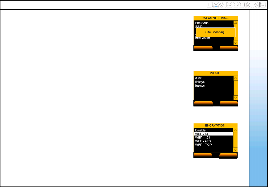
Step.1 - Select MENU > CONFIG > WLAN > SSID > SCAN and a list of available
AP’s will be displayed >select > VIEW on the selected
AP you wish to connect> SELECT> OK.
Step.2 - In the same WLAN settings menu > ENCRYPTION > select the suitable
security setting. For eg: - None
WEP-64 *
WEP-128
WEP-TKIP
WEP-AES
Note: Choose the type of encryption and key with reference
from your IT administrator.
Fig.52 WLAN Scanning Screen
Fig.53 AP List Screen
ACTIVATE BACK
VIEW BACK
Fig.54 Key Save Screen
SELECT BACK
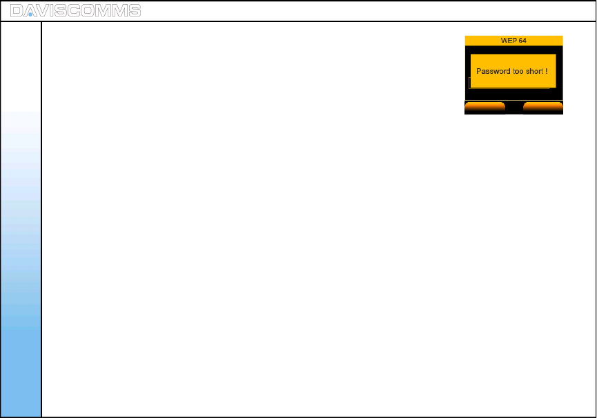
Step.3 - After selecting a security key type >Select Open system
> choose KEY 1 > enter the KEY >click OK..
Note: If the KEY you have input is too short, a warning message
will appear.
- In the same WLAN settings menu > TRANSMIT RATE > for eg: -
select AUTO.
Menu - Configuration
Fig.55 Warning Screen
OK CLEAR
WLAN: Transmit Rate
54
Menu - Configuration
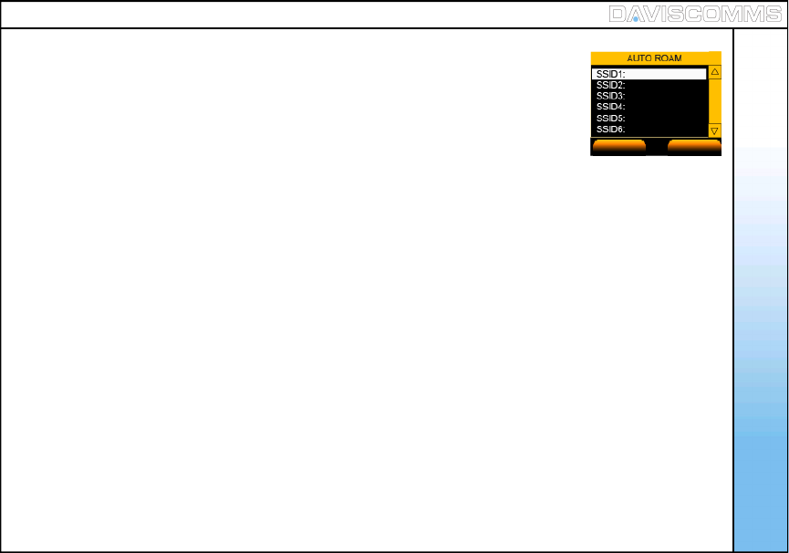
To Auto Roam on a SP Profile
- Go to > MENU >CONFIG >WLAN >AUTO ROAM >AP PROFILE >
select a SSID (edit a SSID account) >OPTIONS >JOIN.
To Edit a SSID Profile
- In the same Auto Roam settings menu > AP PROFILE > select a SSID > OPTIONS
>EDIT>key in a SSID >select a security
setting.
To Delete a SSID Profile
- In the same Auto Roam settings menu > AP PROFILE > select a SSID >OPTIONS
> DELETE.
To Delete all SSID Profiles
- In the same Auto Roam settings menu > AP PROFILE > select a SSID > OPTIONS
> DELETE.
To enable Auto Roam
- In the same Auto Roam settings menu > STATUS > select ENABLE.
WLAN: Auto Roam
OPTIONS BACK
Fig.56 Auto Roam Screen
55
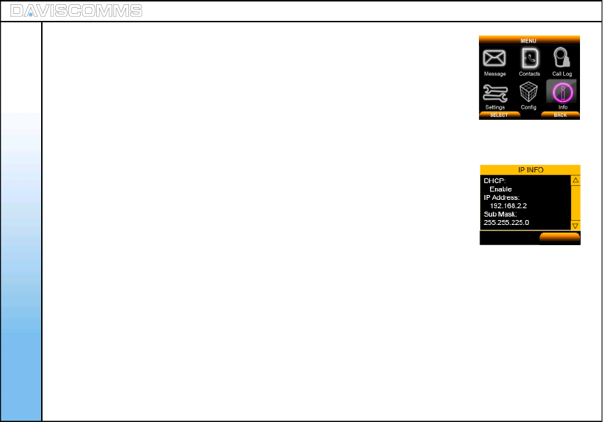
- Select MENU > INFO > select SIP and choose SELECT to view its information.
- Select MENU > INFO > select IP to view your current connection details.
- Select MENU > INFO > select WLAN and choose SELECT to view its information.
-Select MENU > INFO > select GENERAL and choose SELECT to view its information.
Menu - Information
Menu – ( vi ) Information
( 1 ) SIP Information
( 2 ) IP Information
( 3 ) WLAN Information
( 4 ) General Information
Fig.57 Info Selected
Fig.58 IP Information Screen
Information section provides the relevant information of the SIP, IP, WLAN
and General settings.
56
BACK
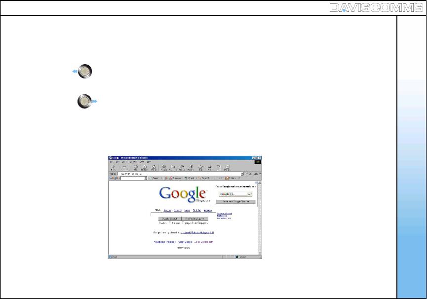
Web Configurator
The Web configurator is a special shortcut function of the phone where it allows the user to update or edit the
phones settings via a web browser on their PC.
57
Step 1 - Left click on the joystick to System info and retrieve IP address
assign to the Cyber phone.
Step 2 - Right click on joystick >scroll and select > WEB CONFIGURATOR.
Step 3 - Open a web browser in your PC and key in the IP address found on your
Cyber phone from step 1 e.g. http://192.168.123.114
5. Web Configurator
58
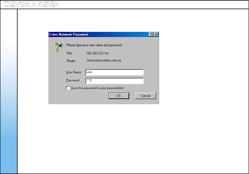
Web Configurator
Step 4 - Enter “user” in User Name and key in “1234” as Password. Click Ok.
59
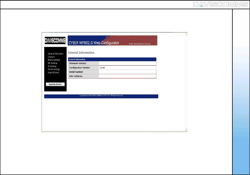
Step 5 - Your web browser will display the page as shown below under General Information
Web Configurator
60
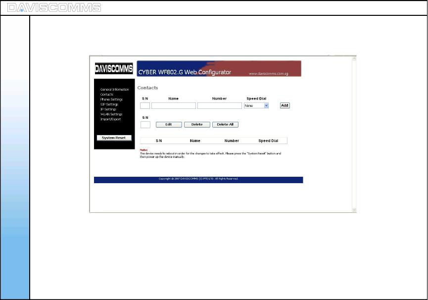
Step 6 - Under general information it contains software details of your phone. Your web browser will display
the page as shown below under Contacts.
This page allows you to view/add/edit/delete a contact to/from your phone.
Web Configurator
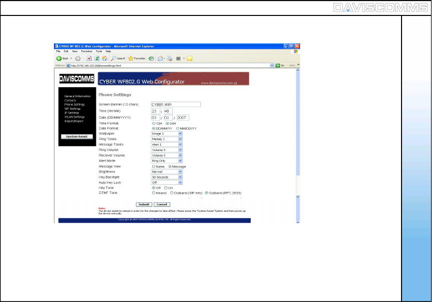
Step 7 - Your web browser will display the page as shown below under Phone Settings.
61
This page allows you to configure the phone settings
Web Configurator
62
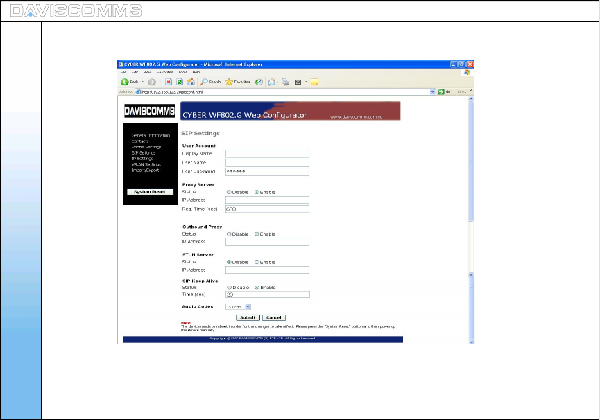
Step 8 - Your web browser will display the page as shown below under SIP Settings.
This page allows you to configure your SIP account settings to the phone, to register to a SIP server.
Web Configurator
63
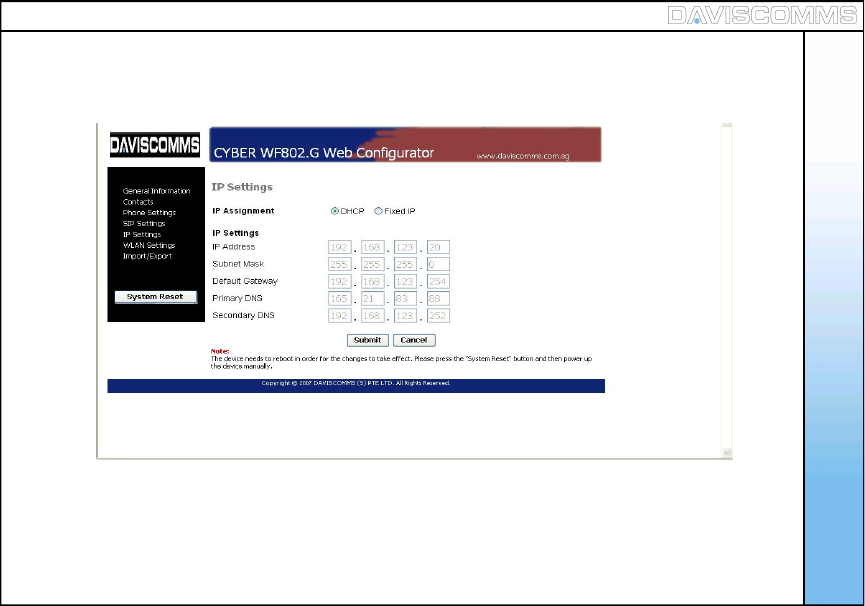
Step 9 - Your web browser will display the page as shown below under IP Settings.
This page allows you to configure a fixed IP setting or set a DCHP setting to automatically assign an IP
address for the phone to connect to the AP of the LAN.
Web Configurator
64
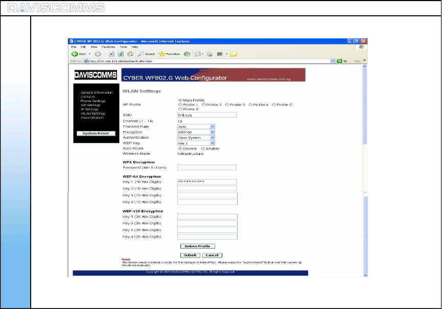
Step 10 - Your web browser will display the page as shown below under WLAN Settings.
This page allows you to set the AP details you require the phone to connect to.
Web Configurator
65
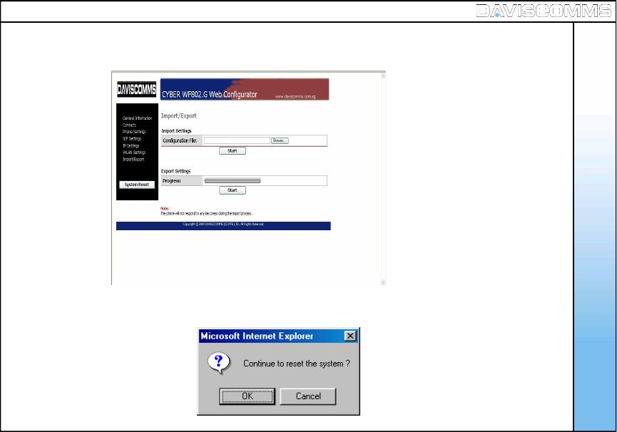
Step 12 - Click on System Reset once you have finalized the settings to complete the web configuration
procedure
Web Configurator
Step 11 - Your web browser will display the page as shown below under IMPORT / EXPORT
66
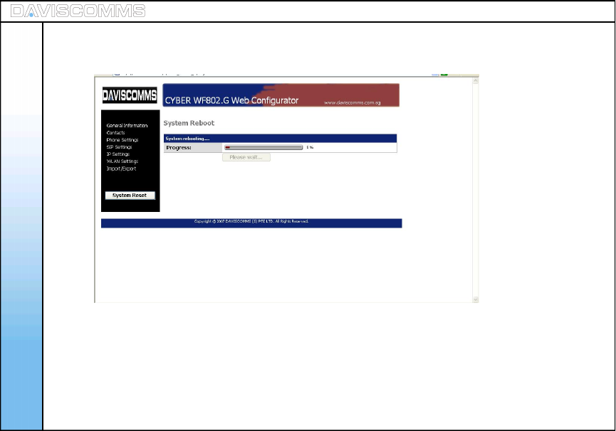
After the progress has completed, the program will trigger your phone to switch off automatically.
Step 14 - Turn on your phone again to connect to the AP of your LAN.
Your phone will connect according to the settings you have configured in web configuration.
Step 13 - After clicking OK to reset the page will display as shown below
Web Configurator
6. Glossary
Glossary
67
AP (Access Point) - A device that connects wireless communication devices together to form a wireless network.
SIP (Session Initiation Protocol) - A application-layer control protocol for creating, modifying, and terminating sessions with
one or more participants. These sessions include internet telephone calls, multimedia distribution and multimedia conferences.
DNS (Domain Name Server) - The IP address of your ISP’s server, which translates the names of websites into IP addresses.
Encryption - Encoding data transmitted in a network.
Firmware - The programming code that runs a networking device.
Gateway - A device that interconnects networks with different, incompatible communications protocols.
IP (Internet Protocol) A protocol used to send data over a network.
IP Address - The address used to identify a computer or device on a network.
ISP (Internet Service Provider) - A company that provides access to the internet.
MAC (Media Access Control) - The unique address that a manufacturer assigns to each networking device.
Outbound Proxy Server - A proxy that receives requests from a client, even though it may not be the server resolved by the
request - URI.
ROAMING - The ability to take a wireless device from the range of one access to another without losing the connection.
SSID (Service Set IDentifier) - Your wireless network’s name.
STUN Server - Simple Traversal of UDP (User Datagram Protocol) through NATs (Network Address Translators) is a network
protocol allowing a client behind a NAT to find out its public address, the type of NAT it is behind and the internet side port
associated by the NAT with a particular local port. This information is used to set up a communication between two hosts that
are both behind NAT routers.
Subnet Mask - An address code that determines the size of the network.
WEP (Wired Equivalent Privacy) - A method of encrypting network data transmitted on a wireless network for greater security.
WLAN (Wireless Local Area Network) - A group of computers and associated devices that communicate with each other
wirelessly.
Health and Safety Information
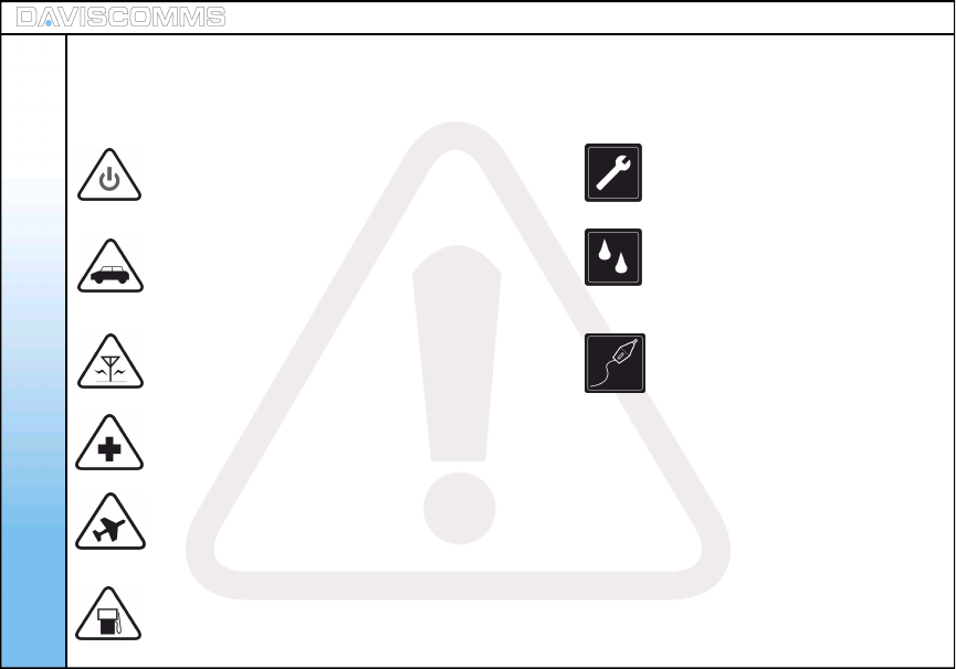
Read these simple guidelines. Failure to comply may be
dangerous or illegal.
SWITCH ON SAFELY Do not switch the
phone on when wireless phone use is
prohibited or when it may cause interference
or danger.
ROAD SAFETY COMES FIRST Obey all
local laws. Always free your hands to operate
the vehicle while driving. Your first consideration
while driving should be road safety.
INTERFERENCE All wireless phones may
be subject to interference. Switch the phone off
near medical equipment.
SWITCH OFF IN HOSPITALS Follow all restrictions.
Switch the phone off near medical equipment.
SWITCH OFF IN AIRCRAFT Follow any restrictions.
Wireless devices can cause interference in aircraft.
SWITCH OFF WHEN REFUELLING Do not use
the phone at a refueling point. Do not use near
fuel or chemicals.
QUALIFIED SERVICE
Only qualified personnel may
install or repair this product.
WATER-RESISTANCE
Your phone is not water-resistant.
Keep it dry.
ENHANCEMENT AND BATTERIES
Use only approved enhancements
and batteries. Do not connect
incompatible products.
68
7. Health and Safety Information

Health and Safety Information
Road Safety
-Your wireless phone gives you the powerful ability to communicate by voice, anywhere and
anytime. But an important responsibility accompanies the benefits of wireless phones, one that
every user must uphold.
-When driving a car, driving is your first responsibility. When using your wireless phone while
driving, follow local regulations in the country or region you are in.
Hearing Aids
-Some digital wireless phones may interfere with some hearing aids. In the event of such
interference, you may wish to consult your hearing aid manufacturer to discuss alternatives.
Potentially Explosive Environments
-Switch off your phone when in any area with a potentially explosive atmosphere, and obey all
signs and instructions. Sparks in such areas could cause an explosion or fire resulting in bodily
injury or even death.
-Areas with a potentially explosive atmosphere are often but not always clearly marked. They
include the areas below decks on boats, chemical transfer or storage facilities, vehicles using
liquefied petroleum gas, such as propane or butane, areas where the air contains chemicals or
particles, such as grain, dust or metal powders, and any other area where you would normally
be advised to turn off your vehicle engine.
69

Health and Safety Information
Precautions when using batteries
-Never use a charger or battery that is damaged in any way.
-Use the battery only for its intended purpose.
-Storing the battery above 45 degrees Celsius (113 degree Fahrenheit) is not recommended.
-Battery charging time depends on the remaining battery charge, the type of battery, and the charger
used. The battery can be charged and discharged hundreds of times, but will gradually wear out.
When the operation time is noticeably shorter than normal, it is time to buy a new battery.
-Use only approved batteries, and recharge your battery only with approved chargers. Disconnect
the charger from the power source when it is not in use. Do not leave the battery connected to a
charger for more than a week, since over charging may shorten its life.
-Extreme temperatures will affect the charging capacity of your battery: it may require cooling or
warming first.
-Do not leave the battery in hot or cold places because the capacity and lifetime of the battery will be
reduced. Try to keep the battery at room temperature. A phone with a hot or cold battery may not
work temporarily, even when the battery is fully charged.
-Do not short circuit the battery. Accidental short circuiting can occur when a metallic object like a
coin, clip or pen may cause a direct connection between the positive and negative terminals of the
battery (metal strips on the battery). For example, do not carry a spare battery in a pocket or bag
where there may be metal objects. Short circuiting the batteries may cause damage to the battery.
-Dispose of used batteries in accordance with local regulations. Always recycle. Do not dispose
of batteries in a fire.
70
FCC Declaration
71
8. FCC Declaration
This device complies with part 15 of the FCC Rules. Operation is subject to the following two conditions:
(1) This device may not cause harmful interference, and
(2) this device must accept any interference received, including interference that may cause
undesired operation.
Note: This equipment has been tested and found to comply with the limits for a Class B digital device,
pursuant to part 15 of the FCC Rules. These limits are designed to provide reasonable protection
against harmful interference in a residential installation. This equipment generates, uses and can
radiate radio frequency energy and, if not installed and used in accordance with the instructions,
may cause harmful interference to radio communications. However, there is no guarantee that
interference will not occur in a particular installation. If this equipment does cause harmful interference
to radio or television reception, which can be determined by turning the equipment off and on, the user
is encouraged to try to correct the interference by one or more of the following measures:--Reorient or
relocate the receiving antenna.--Increase the separation between the equipment and receiver.--Connect
the equipment into an outlet on a circuit different from that to which the receiver is connected.--Consult
the dealer or an experienced radio/TV technician for help.