Dayton Audio Division of Parts Express MCWA60 AMPLIFIER User Manual MCWA60 indd
Dayton Audio Division of Parts Express AMPLIFIER MCWA60 indd
Users Manual
60 WATT CLASS D PLATE
AMPLIFIER with Wii and
BLUETOOTH 4.0 apt X
Model: MCWA60 User Manual
(2)
INTRODUCTION
Congratulations on your purchase of the Dayton Audio MCWA60 60-watt plate amplifier with Wi-Fi and Bluetooth
audio! The MCWA60 is a feature-packed full range Class D plate amplifier that makes it easy to add high-quality Wi-Fi
and AptX Bluetooth 4.0 wireless connectivity to your speakers. In addition to its wireless inputs, the MCWA60 features
RCA, 3.5mm, and optical digital inputs, plus a subwoofer output (LFE).
The MCWA60 is ideal for the project builder or OEM, with endless applications. Use the MCWA60 to build multimedia
speakers, powered monitor speakers, or even retrofit existing speakers! Each Wi-Fi module is serialized for easy
identification when using multiple plate amps, and each plate amp powers its host speaker plus an additional passive
unit with up to 30 watts per channel.
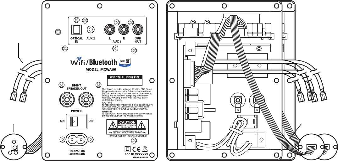
ASSEMBLY
Select a mounting location for the MCWA60 amplifier module that allows the 30" speaker cable to easily reach the
speaker or crossover input terminals. The 30 " lead is factory terminated with 0.205" disconnects for easy connection to
speaker and crossover terminals. Mount the MCWA60 amplifier module into a 3-3/4" (W) x 5-1/2" (H) cut-out in your
cabinet, and bore an 11/16" diameter hole to mount the IR target/BT/Wi-Fi pairing indicator PCB.
Note: For modeling use both 2D and 3D mechanical files are available for download of this plate amplifier.
Files can be found on the daytonaudio.com website.
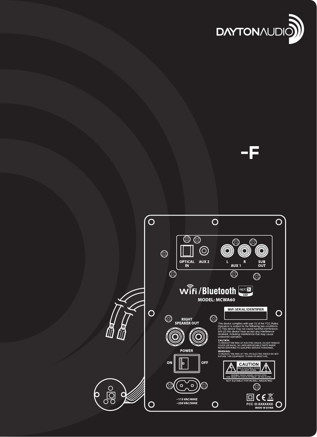
OPTICAL – Connect an S/PDIF Toslink cable to this input.
The Toslink input supports PCM digital audio signals via
an optical cable and a high-quality AKM digital-to-analog
converter.
AUX 2 – Connect a line-level or headphone-level signal
to the 3.5mm AUX 2 input using a 3.5 mm to 3.5mm or
3.5mm to RCA cable.
AUX 1 – Connect a line-level stereo audio signal to the
AUX 1 input using quality RCA style cables.
SUB OUT – Connect a powered subwoofer to the SUB
OUT using a standard RCA style cable. The subwoofer
plays content below 80 Hz when connected; the speaker
outputs remain full-range.
SPEAKER OUT – Connect a remote full-range speaker
to the SPEAKER OUT. Be sure and pay attention to
positive and negative polarity. The amplifier will provide
up to 30 watts into a 4 ohm minimum impedance on
this connection.
AC INPUT – Connect line power to the AC INPUT using the
included non-polarized “figure 8“ style power cord. The
MCWA60 switch-mode power supply accommodates
a full range of operating voltages from 90-230V, and is
double insulated for use with non-grounded line cords.
POWER – Switch to the ON position when operating the
MCWA60 and the OFF position when the unit is not in use.
FRONT BACK
INPUTS/OUTPUTS
The MCWA60 features a variety of input connections to suit a variety of needs:
Internal
Speaker Lead
78cm/30.7"
Pairing
WiFi Plate ~30cm/11.8"
(3)
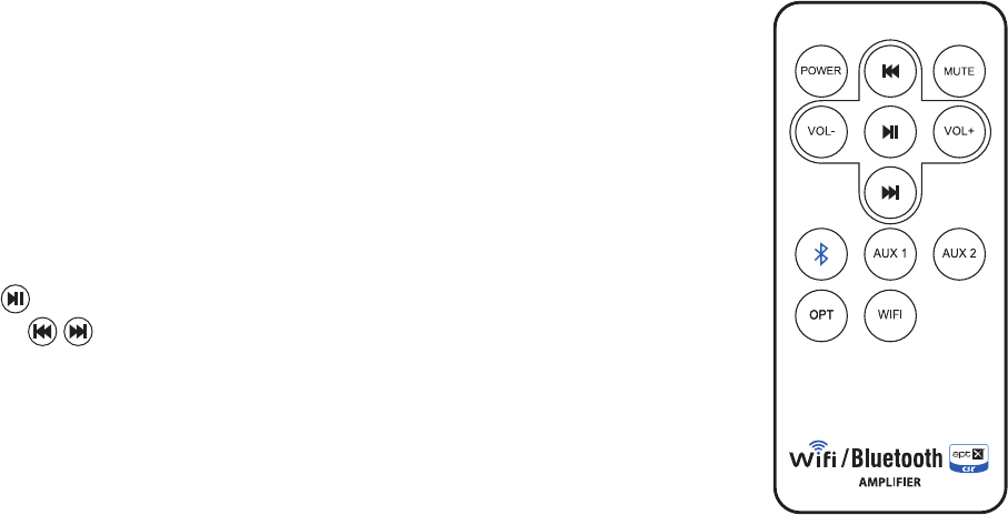
REMOTE CONTROL
POWER – Toggles the power state of the amplifier from STANDBY to ON. When the unit is
ON, the indicator LED will illuminate BLUE. When the unit is in STANDBY, the indicator LED
will illuminate RED. (Note: Turning OFF the rear power switch will turn power completely off
to the unit, disabling the remote.)
VOLUME – Adjusts the volume level of the amplifier. If the source device has a volume
control in itself, set the volume to full then control the volume with the MCWA60 volume
control. As the volume increases or decreases the blue indicator LED will flash. When
volume is at min or MAX, the blue indicator LED will not flash.
MUTE – Press once to temporarily mute the amplifier. The blue indicator LED will flash
slowly while the MCWA60 is muted.
PLAY/PAUSE – Press once to play or pause program audio in Bluetooth mode only.
PREVIOUS/SKIP – Press to move to the beginning of the current song or advance
to the next song in Bluetooth mode only.
AUX 1/2 – Press once to switch to the corresponding analog input on the amplifier. The blue
indicator LED will flash once.
OPTICAL – Press once to switch to the S/PDIF Toslink input on the amplifier. The blue
indicator LED will flash once.
BLUETOOTH – Press to switch to and pair with the Bluetooth input on the amplifier. The
blue indicator LED will flash once.
WiFi – Press once to switch to and pair with the Wi-Fi input on the amplifier. The blue indicator LED will flash once.
OPERATION
Once you have completed installation of the MCWA60 into your project it is best to test the system using a known
operating source component connected to one of the analog inputs. The default state of the amplifier at power-ON is
to enter STANDBY mode; use the remote to turn the power on and select an input to begin listening.
PHYSICAL CONNECTION
Connect an audio source to any of the three external inputs. Permanent connection of sources including CD/BD/DVD
players, television/satellite/cable boxes, game consoles, and other sources are best supported using the OPTICAL or
AUX 1 (RCA) inputs, while portable music players and PCs are best supported by the AUX 2 (3.5mm) input.
WIRELESS CONNECTION – BLUETOOTH®
Bluetooth connectivity provides an easy, wireless connection for a personal audio device such as a tablet or mobile
phone. The MCWA60 utilizes a Bluetooth 4.0 transceiver featuring aptX® decoding for CD quality audio, and also
supports legacy A2DP, AVRCP, HFP, and HSP Bluetooth audio profiles. This is a Class II Bluetooth receiver with a range
of approximately 10 meters.
To pair your device, put the phone or tablet into pairing mode. Press the Bluetooth button on the remote control. Press
“scan“ on the phone or tablet and select the device labeled “DABTA“. The blue indicator LED will illuminate brightly to
show pairing was successful.
Note: The remote control functions PREVIOUS, SKIP, PLAY, and PAUSE are only available for use in Bluetooth mode.
WIRELESS CONNECTION – Wi-Fi
The Wi-Fi connection in the MCWA60 operates using the same principles as your home Wi-Fi internet connection;
however, the MCWA60 does not connect to your home Wi-Fi or to the internet. Instead, it creates its own Wi-Fi
network, which your source device connects to. The Wi-Fi connection provides an easy, wireless connection for a
personal audio device such as a smartphone, tablet, or PC.
Note: Each MCWA60 is assigned a unique Wi-Fi serial Identifier. This number can be found on the amplifier’s face
(same as serial number).
Open the Wi-Fi settings in your smartphone, tablet, or PC. Press the Wi-Fi button on the remote control. Scan for Wi-Fi
networks and select the network labeled DAWAXXX, where “XXX“ is a unique string of numbers assigned to the Wi-Fi
module. Note: In most cases your smartphone, tablet, or PC will lose internet WiFi connectivity while connected to and
streaming audio to the MCWA60 amplifier.
STANDBY MODE
The MCWA60 will automatically switch to standby mode if no signal is sensed for 15 minutes. When a signal is sensed, the
MCWA60 will “wake-up
“
automatically and begin to operate. Power consumption in standby mode is less than 0.5W.
(4)
Dayton Audio ®
SPECIFICATIONS
Power:
Inputs:
Outputs:
Frequency response:
Operating power:
Standby power:
Bluetooth module:
Bluetooth Audio Profiles:
Bluetooth range:
Wi-Fi:
Signal to noise ratio:
2 x 30 Watts RMS (Class D)
AUX 1: 2 x RCA, AUX 2: 3.5mm Stereo, S/PDIF Optical: Toslink
30" lead with 0.205" disconnects, Dual 5-way binding posts,
RCA LFE Output (80 Hz Xover)
45-20,000 Hz
90 ~ 230 Vac, 50/60 Hz, 80Watts
<0.5Watts
V4.0 + EDR, Class II
aptX, A2DP, AVRCP, HFP, and HSP
10 meters
2.4 GHz, Apple AirPlay® compatible
>95dB
Specifications and design subject to modification without notice
Apple and AirPlay are trademarks of Apple Computer, Inc. Registered in the US and other countries.
Last Revised: 11/7/2014
FCC Statement
This equipment has been tested and found to comply with the limits for a Class B digital device, pursuant to Part 15 of the FCC Rules. These
limits are designed to provide reasonable protection against harmful interference in a residential installation. This equipment generates uses
and can radiate radio frequency energy and, if not installed and used in accordance with the instructions, may cause harmful interference to
radio communications. However, there is no guarantee that interference will not occur in a particular installation. If this equipment does
cause harmful interference to radio or television reception, which can be determined by turning the equipment off and on, the user is
encouraged to try to correct the interference by one or more of the following measures:
-- Reorient or relocate the receiving antenna.
-- Increase the separation between the equipment and receiver.
-- Connect the equipment into an outlet on a circuit different from that to which the receiver is connected.
-- Consult the dealer or an experienced radio/TV technician for help.
This device complies with part 15 of the FCC Rules. Operation is subject to the following two conditions:(1) This device may not cause
harmful interference, and (2) this device must accept any interference received, including interference that may cause undesired operation.
Changes or modifications not expressly approved by the party responsible for compliance could void the user's authority to operate the
equipment.
This equipment complies with FCC radiation exposure limits set forth for an uncontrolled environment. This equipment should be installed
and operated with minimum distance 20cm between the radiator & your body.