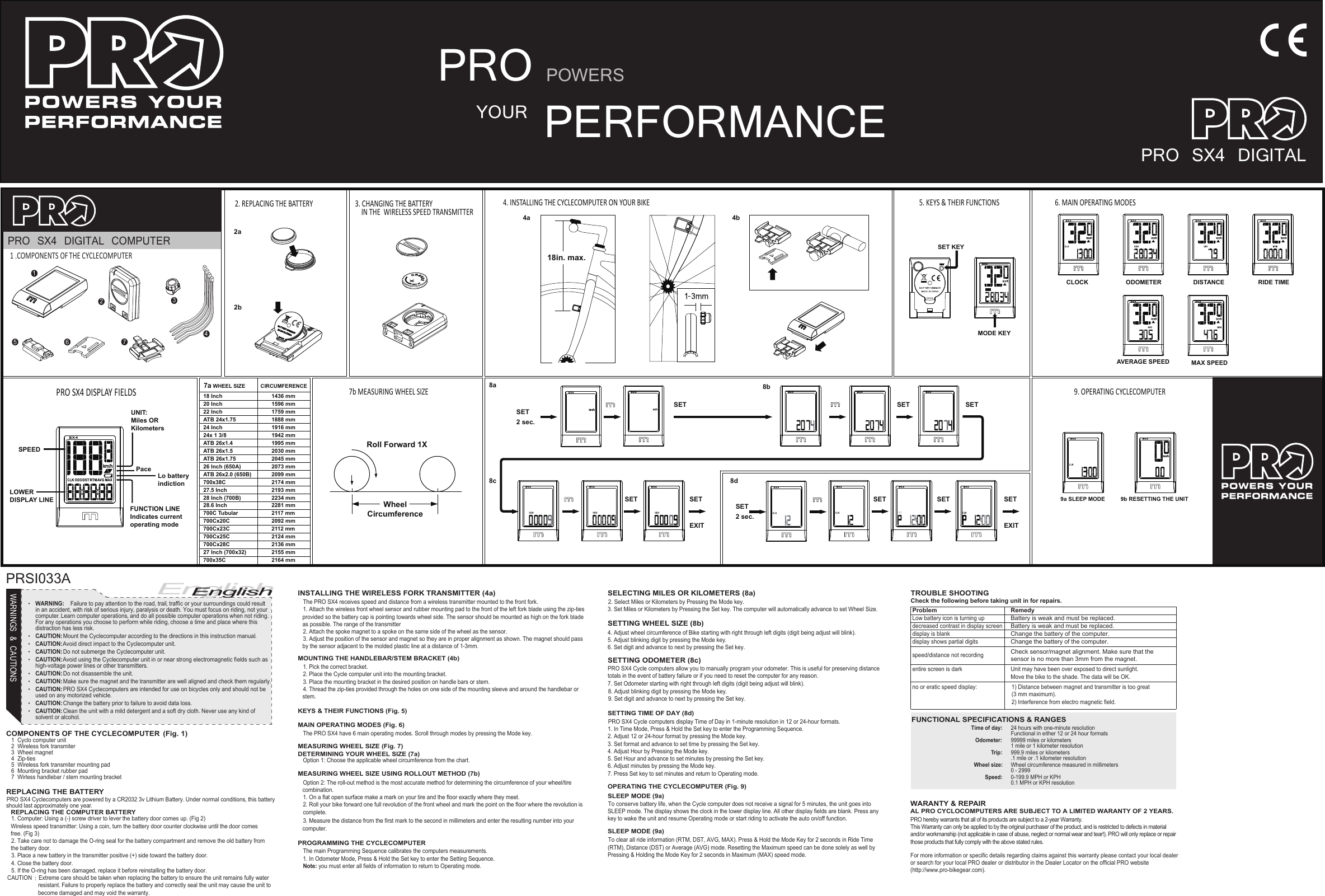
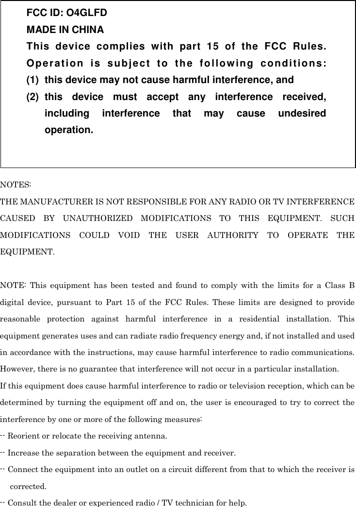
Dayton LFD Bike Speed Transmitter User Manual ALL 000329 PRO SX4 indd

Dayton Industrial Co., Ltd. Bike Speed Transmitter ALL 000329 PRO SX4 indd

User manual

 WARNINGS & CAUTIONS  English  •   WARNING:   Failure to pay attention to the road, trail, traffi c or your surroundings could result in an accident, with risk of serious injury, paralysis or death. You must focus on riding, not your computer. Learn computer operations, and do all possible computer operations when not riding. For any operations you choose to perform while riding, choose a time and place where this distraction has less risk.•    CAUTION:  Mount the Cyclecomputer according to the directions in this instruction manual.•    CAUTION:  Avoid direct impact to the Cyclecomputer unit.•    CAUTION:  Do not submerge the Cyclecomputer unit.•    CAUTION:  Avoid using the Cyclecomputer unit in or near strong electromagnetic fi elds such as high-voltage power lines or other transmitters.•    CAUTION:  Do not disassemble the unit.•    CAUTION:  Make sure the magnet and the transmitter are well aligned and check them regularly.•    CAUTION:  PRO SX4 Cyclecomputers are intended for use on bicycles only and should not be used on any motorized vehicle.•    CAUTION:  Change the battery prior to failure to avoid data loss.•    CAUTION:  Clean the unit with a mild detergent and a soft dry cloth. Never use any kind of solvent or alcohol.     INSTALLING THE WIRELESS FORK TRANSMITTER (4a)     The PRO SX4 receives speed and distance from a wireless transmitter mounted to the front fork.  1. Attach the wireless front wheel sensor and rubber mounting pad to the front of the left fork blade using the zip-ties provided so the battery cap is pointing towards wheel side. The sensor should be mounted as high on the fork bladeas possible. The range of the transmitter       2. Attach the spoke magnet to a spoke on the same side of the wheel as the sensor.   MOUNTING THE HANDLEBAR/STEM BRACKET (4b)    1. Pick the correct bracket.  2. Place the Cycle computer unit into the mounting bracket.    3. Place the mounting bracket in the desired position on handle bars or stem.   4. Thread the zip-ties provided through the holes on one side of the mounting sleeve and around the handlebar or stem.  KEYS & THEIR FUNCTIONS (Fig. 5)  The PRO SX4 have 6 main operating modes. Scroll through modes by pressing the Mode key.  Option 1: Choose the applicable wheel circumference from the chart.   Option 2: The roll-out method is the most accurate method for determining the circumference of your wheel/tire combination.  1. On a flat open surface make a mark on your tire and the floor exactly where they meet.   COMPONENTS OF THE CYCLECOMPUTER  (Fig. 1)    1  Cyclo computer unit  2  Wireless fork transmiter   3  Wheel magnet  4  Zip-ties  5  Wireless fork transmiter mounting pad   6  Mounting bracket rubber pad  7  Wirless handlebar / stem mounting bracket      REPLACING THE BATTERY    PRO SX4 Cyclecomputers are powered by a CR2032 3v Lithium Battery. Under normal conditions, this battery should last approximately one year.  REPLACING THE COMPUTER BATTERY   1. Computer: Using a (-) screw driver to lever the battery door comes up. (Fig 2)Wireless speed transmitter: Using a coin, turn the battery door counter clockwise until the door comes free. (Fig 3)  2. Take care not to damage the O-ring seal for the battery compartment and remove the old battery from the battery door.  3. Place a new battery in the transmitter positive (+) side toward the battery door.    4. Close the battery door.  5. If the O-ring has been damaged, replace it before reinstalling the battery door.   CAUTION:   Extreme care should be taken when replacing the battery to ensure the unit remains fully water resistant. Failure to properly replace the battery and correctly seal the unit may cause the unit to become damaged and may void the warranty.  SELECTING MILES OR KILOMETERS (8a)         SETTING WHEEL SIZE (8b)      SETTING ODOMETER (8c)       2. Select Miles or Kilometers by Pressing the Mode key.3. Set Miles or Kilometers by Pressing the Set key. The computer will automatically advance to set Wheel Size. 4. Adjust wheel circumference of Bike starting with right through left digits (digit being adjust will blink). 5. Adjust blinking digit by pressing the Mode key.  6. Set digit and advance to next by pressing the Set key.PRO SX4 Cycle computers allow you to manually program your odometer. This is useful for preserving distance totals in the event of battery failure or if you need to reset the computer for any reason.    SETTING TIME OF DAY (8d)  PRO SX4 Cycle computers display Time of Day in 1-minute resolution in 12 or 24-hour formats.1. In Time Mode, Press & Hold the Set key to enter the Programming Sequence.2. Adjust 12 or 24-hour format by pressing the Mode key.3. Set format and advance to set time by pressing the Set key.4. Adjust Hour by Pressing the Mode key.5. Set Hour and advance to set minutes by pressing the Set key.6. Adjust minutes by pressing the Mode key.7. Press Set key to set minutes and return to Operating mode.  8. Adjust blinking digit by pressing the Mode key.    TROUBLE SHOOTING   Check the following before taking unit in for repairs.  Problem      Remedy   Battery is weak and must be replaced.Low battery icon is turning up decreased contrast in display screenBattery is weak and must be replaced.display is blank Change the battery of the computer. display shows partial digits Change the battery of the computer. Check sensor/magnet alignment. Make sure that the sensor is no more than 3mm from the magnet.speed/distance not recording Unit may have been over exposed to direct sunlight. Move the bike to the shade. The data will be OK. entire screen is dark FUNCTIONAL SPECIFICATIONS & RANGES    Time of day:  24 hours with one-minute resolutionFunctional in either 12 or 24 hour formats   Odometer:  99999 miles or kilometers 1 mile or 1 kilometer resolution  Trip:  999.9 miles or kilometers.1 mile or .1 kilometer resolution  Wheel size:  Wheel circumference measured in millimeters 0 - 2999  Speed:  0-199.9 MPH or KPH 0.1 MPH or KPH resolution  WARANTY & REPAIR  AL PRO CYCLOCOMPUTERS ARE SUBJECT TO A LIMITED WARANTY OF 2 YEARS.PRO hereby warrants that all of its products are subject to a 2-year Warranty.This Warranty can only be applied to by the original purchaser of the product, and is restricted to defects in material and/or workmanship (not applicable in case of abuse, neglect or normal wear and tear!). PRO will only replace or repair those products that fully comply with the above stated rules.For more information or specific details regarding claims against this warranty please contact your local dealer or search for your local PRO dealer or distributor in the Dealer Locator on the official PRO website (http://www.pro-bikegear.com).PRSI033APROPERFORMANCEYOURPOWERSPRO SX4 DIGITALPRO SX4 DIGITAL COMPUTER12347651 .COMPONENTS OF THE CYCLECOMPUTERCLK DST RTMAVG MAXODOUNIT:Miles ORKilometersPaceFUNCTION LINEIndicates current operating modeLo battery indictionSPEEDLOWERDISPLAY LINEPRO SX4 DISPLAY FIELDS6. MAIN OPERATING MODESCLOCK ODOMETER DISTANCE RIDE TIMEAVERAGE SPEED MAX SPEED9. OPERATING CYCLECOMPUTER9a SLEEP MODE 9b RESETTING THE UNIT5. KEYS & THEIR FUNCTIONSODOMODE KEYSET KEY8b 8d 8a8cUNIT:Miles ORKilometersPaceFUNCTION LINEIndicates current operating modeLo battery indictionSPEEDLOWERDISPLAY LINEPRO SX4 DISPLAY FIELDS7a WHEEL SIZE CIRCUMFERENCE18 Inch 1436 mm7b MEASURING WHEEL SIZEWheelCircumferenceRoll Forward 1XODOODOODO2. REPLACING THE BATTERY 3. CHANGING THE BATTERY     IN THE  WIRELESS SPEED TRANSMITTER4. INSTALLING THE CYCLECOMPUTER ON YOUR BIKE2a2b4b 20 Inch 1596 mm22 Inch 1759 mmATB 24x1.75 1888 mm24 Inch 1916 mm24x 1 3/8 1942 mmATB 26x1.4 1995 mm2030 mm2045 mm26 Inch (650A) 2073 mmATB 26x2.0 (650B) 2099 mm700x38C 2174 mm27.5 Inch 2193 mm28 Inch (700B) 2234 mm28.6 Inch 2281 mm700C Tubular 2117 mm2092 mm2112 mm2124 mm2136 mm2155 mm2164 mmATB 26x1.5ATB 26x1.75700Cx20C700Cx23C700Cx25C700Cx28C27 Inch (700x32)700x35CSETSET2 sec.SET SETSETEXITCLKSETSET2 sec.SET SETEXITSET18in. max.4a English   3. Adjust the position of the sensor and magnet so they are in proper alignment as shown. The magnet should passby the sensor adjacent to the molded plastic line at a distance of 1-3mm.MAIN OPERATING MODES (Fig. 6)MEASURING WHEEL SIZE (Fig. 7)DETERMINING YOUR WHEEL SIZE (7a)MEASURING WHEEL SIZE USING ROLLOUT METHOD (7b)  2. Roll your bike forward one full revolution of the front wheel and mark the point on the floor where the revolution is  complete.   3. Measure the distance from the first mark to the second in millimeters and enter the resulting number into your  computer.PROGRAMMING THE CYCLECOMPUTER  The main Programming Sequence calibrates the computers measurements.   1. In Odometer Mode, Press & Hold the Set key to enter the Setting Sequence.   Note: you must enter all fields of information to return to Operating mode.  7. Set Odometer starting with right through left digits (digit being adjust will blink).  9. Set digit and advance to next by pressing the Set key.OPERATING THE CYCLECOMPUTER (Fig. 9)  To conserve battery life, when the Cycle computer does not receive a signal for 5 minutes, the unit goes into SLEEP mode. The display shows the clock in the lower display line. All other display fields are blank. Press any key to wake the unit and resume Operating mode or start riding to activate the auto on/off function.SLEEP MODE (9a)SLEEP MODE (9a)  To clear all ride information (RTM, DST, AVG, MAX). Press & Hold the Mode Key for 2 seconds in Ride Time (RTM), Distance (DST) or Average (AVG) mode. Resetting the Maximum speed can be done solely as well by Pressing & Holding the Mode Key for 2 seconds in Maximum (MAX) speed mode.1) Distance between magnet and transmitter is too great (3 mm maximum).2) Interference from electro magnetic field.no or eratic speed display:
 NOTES: THE MANUFACTURER IS NOT RESPONSIBLE FOR ANY RADIO OR TV INTERFERENCE CAUSED  BY  UNAUTHORIZED  MODIFICATIONS  TO  THIS  EQUIPMENT.  SUCH MODIFICATIONS  COULD  VOID  THE  USER  AUTHORITY  TO  OPERATE  THE EQUIPMENT.  NOTE:  This  equipment  has  been  tested  and  found  to  comply  with  the  limits  for  a  Class  B digital  device,  pursuant  to  Part  15  of  the  FCC  Rules.  These  limits  are  designed  to  provide reasonable  protection  against  harmful  interference  in  a  residential  installation.  This equipment generates uses and can radiate radio frequency energy and, if not installed and used in accordance with the instructions, may cause harmful interference to radio communications. However, there is no guarantee that interference will not occur in a particular installation. If this equipment does cause harmful interference to radio or television reception, which can be determined by  turning the equipment off and on, the user is encouraged to try to correct the interference by one or more of the following measures: -- Reorient or relocate the receiving antenna. -- Increase the separation between the equipment and receiver. -- Connect the equipment into an outlet on a circuit different from that to which the receiver is corrected. -- Consult the dealer or experienced radio / TV technician for help. FCC ID: O4GLFD MADE IN CHINA This  device  complies  with  part  15  of  the  FCC  Rules. Operation  is  subject  to  the  following  conditions: (1)  this device may not cause harmful interference, and (2)  this  device  must  accept  any  interference  received, including  interference  that  may  cause  undesired operation.

Navigation menu