User Manual

EN
NODE 1.1 & NODE 2.1
Quick Start Guide
About this manual
Please read this manual carefully. If you do not understand the
information, or you have a question that this manual does not cover,
consult your Bontrager dealer or download the complete instruction
manual from www.bontrager.com/support/owners_manuals.
BT11_EN_ES_FR_DE_JA_NODE_QSG_update.indd 1 12/21/11 9:31 AM
2
A
BD E G
F
C
I
H
J
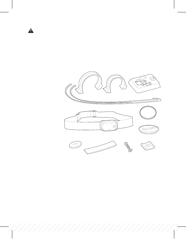
A Handlebar clamp
B Rubber pad
C Brackets
D Battery
E Rubber shim
F Zip ties
G Screw & washer
H Battery cover
I Rubber o-ring
J Heart rate strap
(NODE 2.1 only)
Safety
When riding your bicycle, do not stare at the computer for a long time.
If you do not watch the road, you could hit an obstacle, which might
cause you to lose control and fall.
Parts List
Tools required
+ Screwdriver, Phillips type
+ Coin
BT11_EN_ES_FR_DE_JA_NODE_QSG_update.indd 2 12/21/11 9:31 AM
3
EN
Installation
Step 1: Install the Speed Sensor
Your NODE is not packed with a speed sensor. See your sensor packaging for
sensor installation instructions.
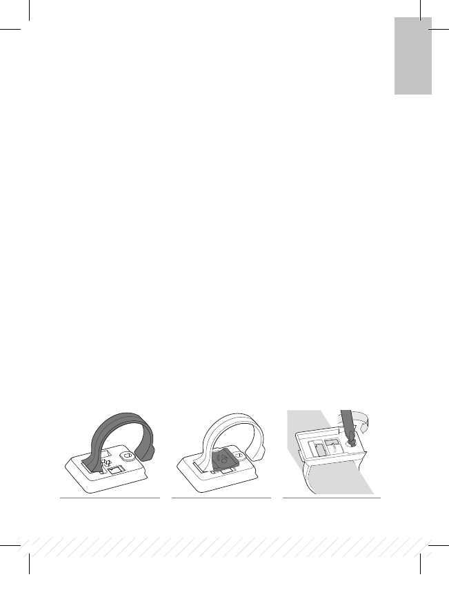
Step 2: Attach the computer base
Attach to a handlebar
+ Insert the correct handlebar clamp (A) into the computer base (C) (Figure 1).
+ Slide the head of the handlebar clamp to the end of the slot in the
computer base.
+ Insert the rubber pad (B) with logo into the back of the computer base
(Figure 2).
+ With the screw hole toward the back of the bike, wrap the handlebar clamp
around the handlebar.
+ Insert the screw and washer (G) and tighten with the screwdriver until
the computer base no longer rotates on the handlebar (Figure 3). Do
not overtighten.
Figure 1. Handlebar clamp in
back of computer base.
Figure 2. Pad inserted in
computer base.
Figure 3. Tighten screw.
BT11_EN_ES_FR_DE_JA_NODE_QSG_update.indd 3 12/21/11 9:31 AM
4
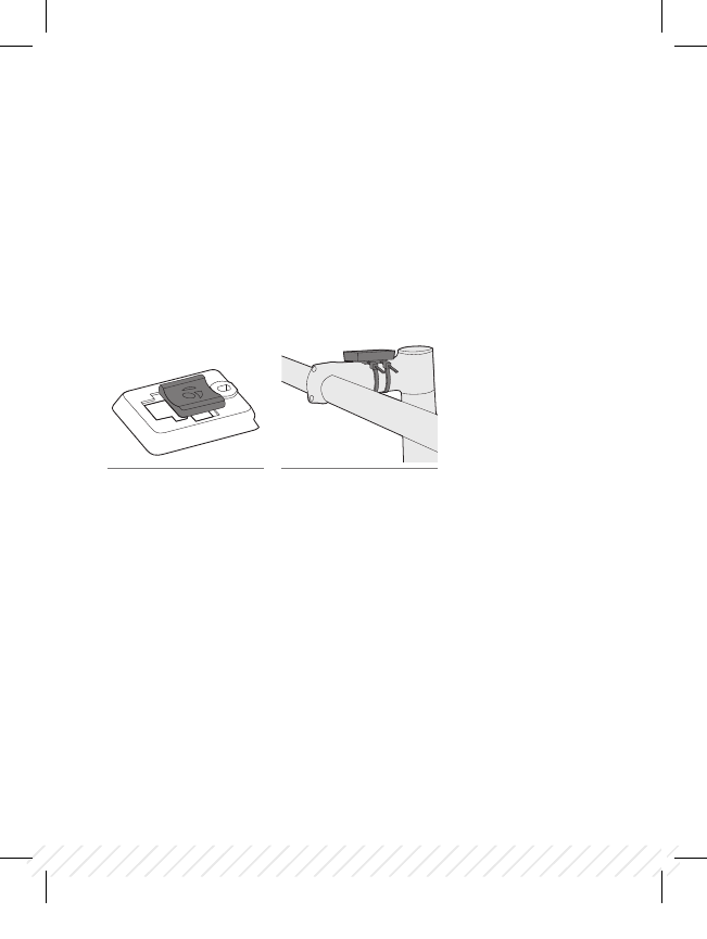
Figure 4. Pad inserted in
computer base.
Figure 5. Base on stem.
Attach to a stem
+ Insert the rubber pad (B) with logo into the back of the computer base (C)
(Figure 4).
+ Position the computer base on the stem with the screw hole toward the back
of the bike (Figure 5).
+ Secure the computer base to the stem using zip-ties (F).
BT11_EN_ES_FR_DE_JA_NODE_QSG_update.indd 4 12/21/11 9:31 AM
5
EN
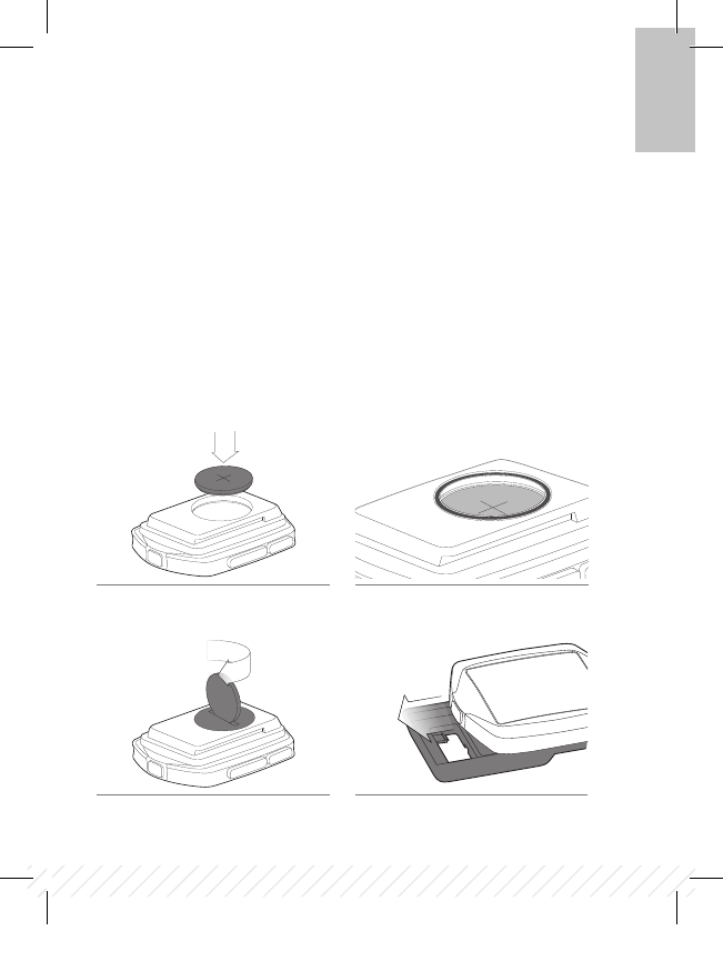
Step 3: Install the battery
+ Insert the supplied battery (D) with the ‘+’ facing up or out (Figure 6).
+ Press the rubber o-ring (I) into the groove around the battery in the computer.
(Figure 7)
+ Place the battery cover (H) over the battery with the slot facing upward.
+ Turn the cover clockwise with a coin. (Figure 8)
+ Slide the computer into the computer base (Figure 9) being careful not to
press any buttons.
Figure 8. Turn cover clockwise with coin.
Figure 7. Insert rubber o-ring into groove.Figure 6. Battery Orientation
During Installation.
Figure 9. Slide computer into
computer base.
BT11_EN_ES_FR_DE_JA_NODE_QSG_update.indd 5 12/21/11 9:31 AM
6
Step 4: Program the computer
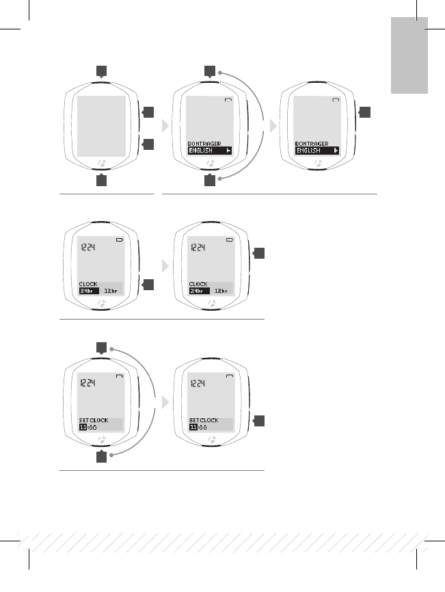
4:1. Wake the computer:
Images and words appear on the screen, proceed to step 4.2
If the screen is blank, push any button on the computer
4:2. Select the language:
To change the language (choose English, Francais, Espanol, Deutsch), press T or B
To save the language and proceed to the next function, press s1
4:3. Select clock:
To change the type of clock (choose 12HR or 24HR), press s2
To save the clock and proceed to the next function, press s1
4:4. Set hours:
To change the hours, press T or B
To set the hours and proceed to minutes, press s2
BT11_EN_ES_FR_DE_JA_NODE_QSG_update.indd 6 12/21/11 9:31 AM
7
4:1.
4:3.
4:4.
4:2.
s1 s1
s1
s2
s2
s2
B
B
B
T
T
T
EN
or
or
BT11_EN_ES_FR_DE_JA_NODE_QSG_update.indd 7 12/21/11 9:31 AM
8
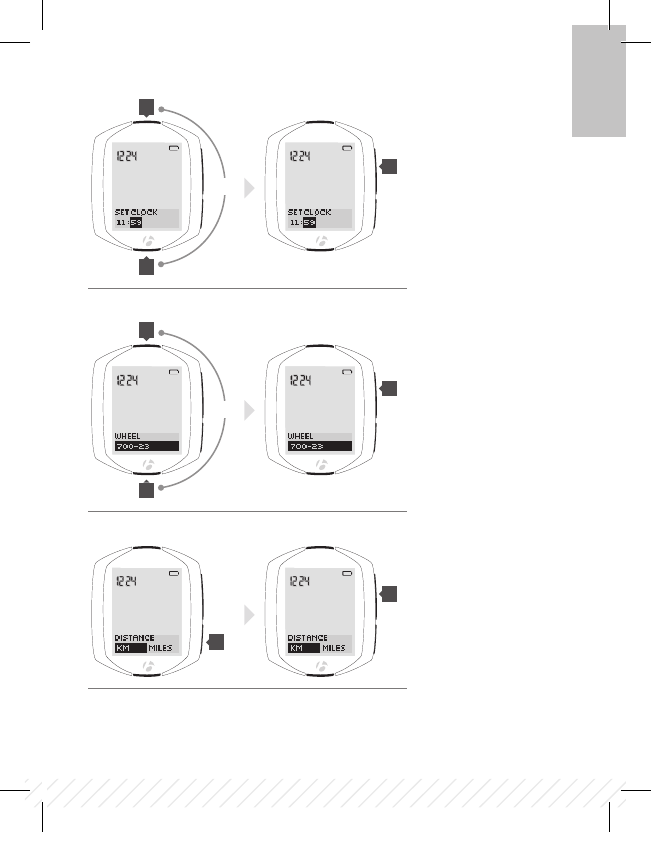
4:5. Set the minutes:
To change the minutes, press T or B
If desired, you can go back to the hours in the previous step by pressing s2
To save the SET CLOCK (time) and proceed to the next function, press s1
4:6. Set the wheel size:
To change the wheel size (choose from the wheel size menu), press T or B
To set a custom wheel size, see the Complete NODE Manual at Bontrager.com
To save the wheel and proceed to the next function, press s1
Wheel size menu
700 x 20
700 x 23
700 x 25
700 x 28
700 x 32
700 x 35
700 x 38
26 x 1.5
26 x 1.9
26 x 2.0
26 x 2.1
26 x 2.2
Custom
4:7. Set units:
To change units (choose KM or MILES), press s2
To save the Units and proceed to the Odometer function, press s1
BT11_EN_ES_FR_DE_JA_NODE_QSG_update.indd 8 12/21/11 9:31 AM
9
4:5.
4:6.
4:7.
s1
s1
s1
s2
B
B
T
T
EN
or
or
BT11_EN_ES_FR_DE_JA_NODE_QSG_update.indd 9 12/21/11 9:31 AM
10
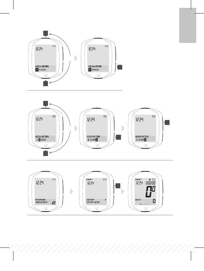
4:8. Set odometer:
To skip this step and leave the value at 00000, press s1 and go to step 4:10
To change the highlighted number, press T or B
To select a value and proceed to the next digit, press s2
4:9. Repeat for each of the other four digits:
To change the highlighted number, press T or B
To select a value and proceed to the next digit, press s2
If desired, you can go back to the first digit (and then the other digits) by pressing s2
To save the odometer and proceed to the next process, press s1
4:10. Activate sensors:
Speed: spin the wheel
Cadence: rotate the crank arm
Heart rate: wear the chest strap
Power: rotate the crank arm (or, for a hub sensor, turn the wheel)
4:11. Wait for pairing to complete:
Note: the Node computer must be within 5 feet (1.5 meters) of the installed sensor(s).
4:12. Finish programming:
When the screen shows “Setup Complete,” press s1 to save all your settings and
switch to the Ride mode.
BT11_EN_ES_FR_DE_JA_NODE_QSG_update.indd 10 12/21/11 9:31 AM
11
4:8.
4:9.
4:11. 4:12.
s1
s1
s2
s2
B
B
T
T
EN
or
or
BT11_EN_ES_FR_DE_JA_NODE_QSG_update.indd 11 12/21/11 9:31 AM

12
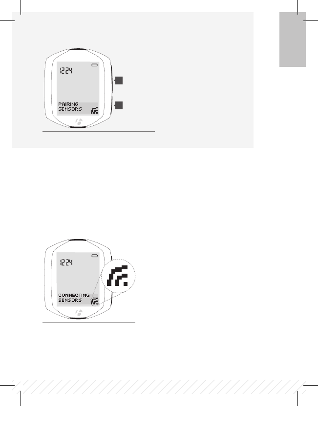
Force pair
If the NODE fails to pair with a sensor, you can force the pairing process:
In RIDE mode, hold s1 and s2 for three seconds (Figure 11) and activate
sensors.
Step 5: Enjoy your ride
Starting a ride from sleep mode
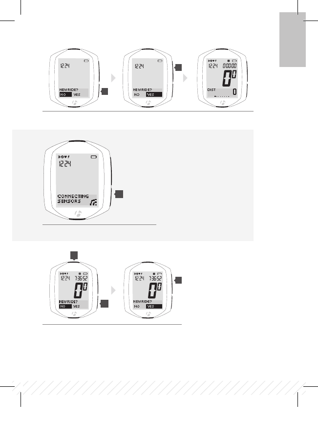
Step 1: Connect sensors
Activate sensors
During the connecting process, the display shows CONNECTING SENSORS and
the lower right corner of the display flashes the ‘receiving’ icon (Figure 12).
BT11_EN_ES_FR_DE_JA_NODE_QSG_update.indd 12 12/21/11 9:31 AM
13
s1
s2
Figure 11. Force pair.
(3 seconds)
(3 seconds)
Figure 12. Connecting to sensor.
EN
BT11_EN_ES_FR_DE_JA_NODE_QSG_update.indd 13 12/21/11 9:31 AM
14
Step 2: Select new ride
+ To change the value (choose YES or NO), press s2 (Figure 13)
+ To select, press s1
Step 3: Enjoy your ride
Force connect
If your NODE did not connect correctly, you can “force connect,” making the
Node repeat the connecting procedure. In RIDE mode, hold s2 for three
seconds and activate sensors (Figure 14).
Ending a ride
+ Hold T for 3 seconds
+ To change the value (choose YES or NO), press s2 (Figure 15)
+ To select press s1
BT11_EN_ES_FR_DE_JA_NODE_QSG_update.indd 14 12/21/11 9:31 AM
15
s1
s1
s2
s2
s2
T
Figure 13.
Figure 14. Force connect.
Figure 15. Choose YES or NO.
(3 seconds)
EN
BT11_EN_ES_FR_DE_JA_NODE_QSG_update.indd 15 12/21/11 9:31 AM

www.bontrager.com
Bontrager & Bontrager B-Dot are registered trademarks of Trek Bicycle Corporation.
©2011 Trek Bicycle Corporation, Waterloo, Wisconsin 53594 USA. All rights reserved.
BT11_EN_ES_FR_DE_JA_NODE_QSG_update.indd 16 12/21/11 9:31 AM
FCC Rules Part 15
Operation is subject to the following two conditions:
(1) This device may not cause harmful interference and
(2) It must accept any interference received, including interference that may cause undesired
operation.
FCC ID: O4GNODE
IC: 7666A-NODE
IC Statement
This device complies with Industry Canada license-exempt RSS standard(s).
Operation is subject to the following two conditions: (1) this device may not cause interference, and
(2) this device must accept any interference, including interference that may cause undesired
operation of the device. The device meets the exemption from the routine evaluation limits in section
2.5 of RSS 102 and users can obtain Canadian information on RF exposure and compliance.
Le présent appareil est conforme aux CNR d'Industrie Canada applicables aux appareils radio
exempts de licence. L’exploitation est autorisée aux deux conditions suivantes: (1) I’appareil ne doit
pas produire de brouillage, et (2) I’utilisateur de I’appareil doit accepter tout brouillage
radioélectrique subi, même si le brouillage est susceptible d’en compromettre le fonctionnement. Le
dispositif rencontre I’exemption des limites courantes d’évaluation dans la section 2.5 de RSS 102
et les utilisateurs peuvent obtenir I’information canadienne sur I’exposition et la conformité de rf.
This device complies with part 15 of the FCC Rules.
Changes or modifications not expressly approved by the party responsible for compliance could void the
user's authority to operate the equipment.