Dcm Speakers Ft10 Users Manual FT12, 10, 6, AND 6C Owners (21A6479)
FT6 DCMFT12_10_6_6CManual
FT6C to the manual 3c6da452-391b-d294-494d-05e54d93f68a
2015-02-03
: Dcm-Speakers Dcm-Speakers-Ft10-Users-Manual-465566 dcm-speakers-ft10-users-manual-465566 dcm-speakers pdf
Open the PDF directly: View PDF ![]() .
.
Page Count: 4
21A6479
FT6C
FULL-TIME SPEAKERS
OWNER'S MANUAL
FT10
FT12
FT6
1 Mitek Plaza
Winslow, IL 61089
815-367-3000
800-225-5689

INTRODUCTION
Congratulations on your purchase of DCM Full Time Loudspeakers. Your new
speakers represent the latest technologies in loudspeaker design and manufac-
turing. They will provide outstanding performance and years of listening enjoy-
ment. Please take time to read through this manual thoroughly to insure you get
maximum performance out of your new loudspeakers.
FEATURES
• Video shielding for placement near a TV or monitor (FT6C)
• 19mm dome tweeter
• Internally braced high density MDF cabinets
• Nickel-plated 5-way binding posts
• Black ash finish to blend in with any decor
• DCM 10 year limited warranty
SPEAKER PLACEMENT
MAIN LEFT AND RIGHT CHANNELS
FT12, FT10, FT6
All DCM Full Time Loudspeakers have been engineered to combine deep power-
ful bass with crisp, natural high frequency performance. Because there are many
factors that affect loudspeaker performance, there is no universal rule for speaker
location. Best results will be obtained with some experimentation using the fol-
lowing guidelines.
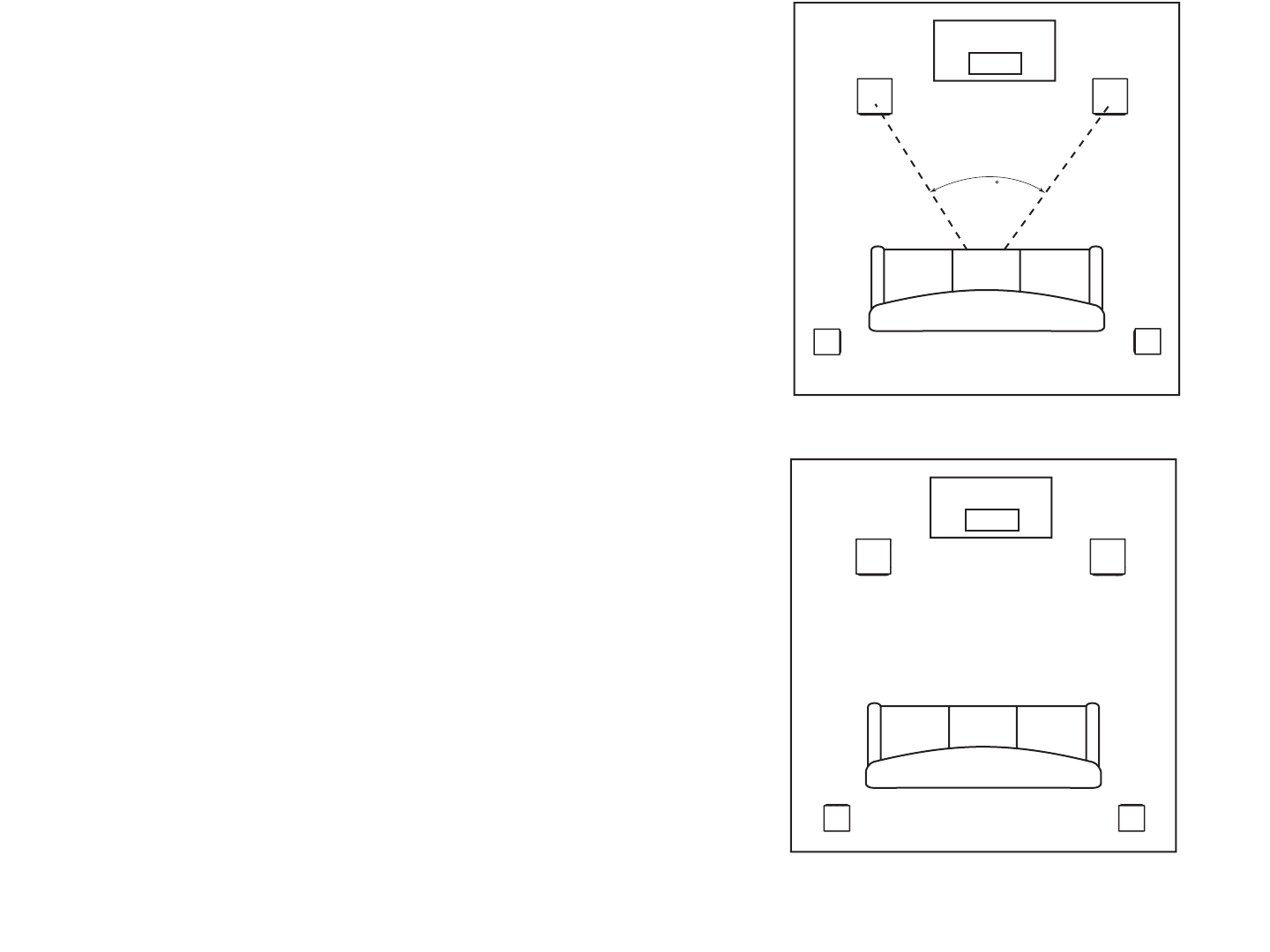
To achieve the most realistic stereo image, position the speakers so that an
equilateral triangle is formed between the speakers and the listening position
(Figure 1). Turning the speakers slightly towards the listening position can
improve the image focus.
Bass loudness can be increased by moving the speakers closer to the rear wall.
This sometimes can degrade the stereo image. Use your judgement as to what
location best fits your preferences.
SURROUND LEFT AND RIGHT CHANNELS
FT6
If you are using the FT6 for rear channel speakers in a home theater application
they should be placed to the side and slightly behind the listening position (Figure
1). If this is not practical, they can be placed on the rear wall to either side of the
listening position (Figure 2). For best results, the surround speakers should be
spaced equal distances from the listening position with the tweeters at or above
ear level.
CARE AND MAINTENANCE
Your speakers are designed to work with a wide range of electronic components.
As little as 20 watts per channel can provide enough power for most applications.
If you have a large room or prefer louder listening levels, more power may be
required.
Caution: When choosing an amplifier, do not exceed the power
rating of the speaker. If you hear very high levels of audible dis-
tortion you are exceeding the capabilities of the system. Damage
can occur from this distortion, turn the volume back down until the
distortion disappears.
Use the following guidelines to maintain the appearance of your speakers. Use
a soft, damp cloth to clean the speaker cabinet. Avoid using harsh detergents or
cleaning fluids. Remove the grills to vacuum and remove dust. Do not vacuum
any of the speaker components, permanent damage could occur.
TECHNICAL ASSISTANCE
For additional technical assistance you can visit our web site at
www.dcmspeakers.com. Otherwise, our technical service representatives can be
reached by phone: 1-877-DCM-LOUD or by email: technical@dcmspeakers.com.
DCM WARRANTY INFORMATION
All FT12, FT10, FT6 and FT6C Speaker Cabinets purchased in the United States from
an authorized DCM dealer are guaranteed against defects in material and workman-
ship for a period ten years from the date purchased by the end user, and limited to the
original retail purchaser of the product.
DCM disclaims any liability for other incurred damages resulting from product defects.
Any expenses incurred in the removal and reinstallation of product is not covered by
this warranty. DCM's total liability will not exceed the purchase price of the product.
This warranty is valid in the United States only.
Proof of purchase is required when requesting service, so please retain your sales receipt
and take a moment to register your warranty on line @www.dcmspeakers.com.
SPECIFICATIONS
FT6
Driver Compliment
Woofer- 6-1/2” Polypropylene cone, butyl rubber surround
Tweeter- 19mm dome, ferrofluid cooled
Frequency Response: 55Hz - 20kHz
Impedance: 8 ohms nominal
Power Handling: 100 watts RMS / 200 watts peak music
Sensitivity: 89dB 1W/1M
Shipping Weight: 20 lbs.
Dimensions: 12 3/4” H x 7 1/2” W x 8 1/2” D
FT6C
Driver Compliment
Woofer- (2) 6-1/2” Polypropylene cone, butyl rubber surround
Tweeter- 19mm dome, ferrofluid cooled
Frequency Response: 60Hz - 20kHz
Impedance: 8 ohms nominal
Power Handling: 100 watts RMS /200 watts peak music
Sensitivity: 92dB 1W/1M
Shipping Weight: 16 lbs.
Dimensions: 7 1/2” H x 17 5/8” W x 8” D
FT10
Driver Compliment
Woofer- 10” Powder coated composite pulp cone
Midrange- 6-1/2" Polypropylene cone, butyl rubber surround
Tweeter- 19mm dome, ferrofluid cooled
Frequency Response: 30Hz - 20kHz
Impedance: 8 ohms nominal
Power Handling: 200 watts RMS /400 watts peak music
Sensitivity: 92dB 1W/1M
Shipping Weight: 42 lbs.
Dimensions: 31 7/16” H x 11 1/8” W x 14 5/16” D
FT12
Driver Compliment
Woofer- 12” Powder coated composite pulp cone
Midrange- 6-1/2" Polypropylene cone, butyl rubber surround
Tweeter- 19mm dome, ferrofluid cooled
Frequency Response: 25Hz - 20kHz
Impedance: 8 ohms nominal
Power Handling: 250 watts RMS / 500 watts peak music
Sensitivity: 94dB 1W/1M
Shipping Weight: 51 lbs.
Dimensions: 35” H x 13 1/8” W x 16 1/16” D
RIGHT
FRONT
LEFT
FRONT
CENTER
CHANNEL
LEFT
REAR
RIGHT
REAR
FIGURE 1 Typical Loudspeaker Placement
LISTENING AREA
45
RIGHT
FRONT
LEFT
FRONT
CENTER
CHANNEL
LEFT
REAR
RIGHT
REAR
FIGURE 2 Alternate Loudspeaker Placement
LISTENING AREA
CENTER CHANNEL
FT6C
When using the FT6C as a center channel speaker in a home theater application
the following guidelines should be used for optimum performance.
Locate the speaker as close to the center of your TV or monitor as possible
(Figure 1). This will anchor the central image of your home theater to the location
of the images seen on the screen.
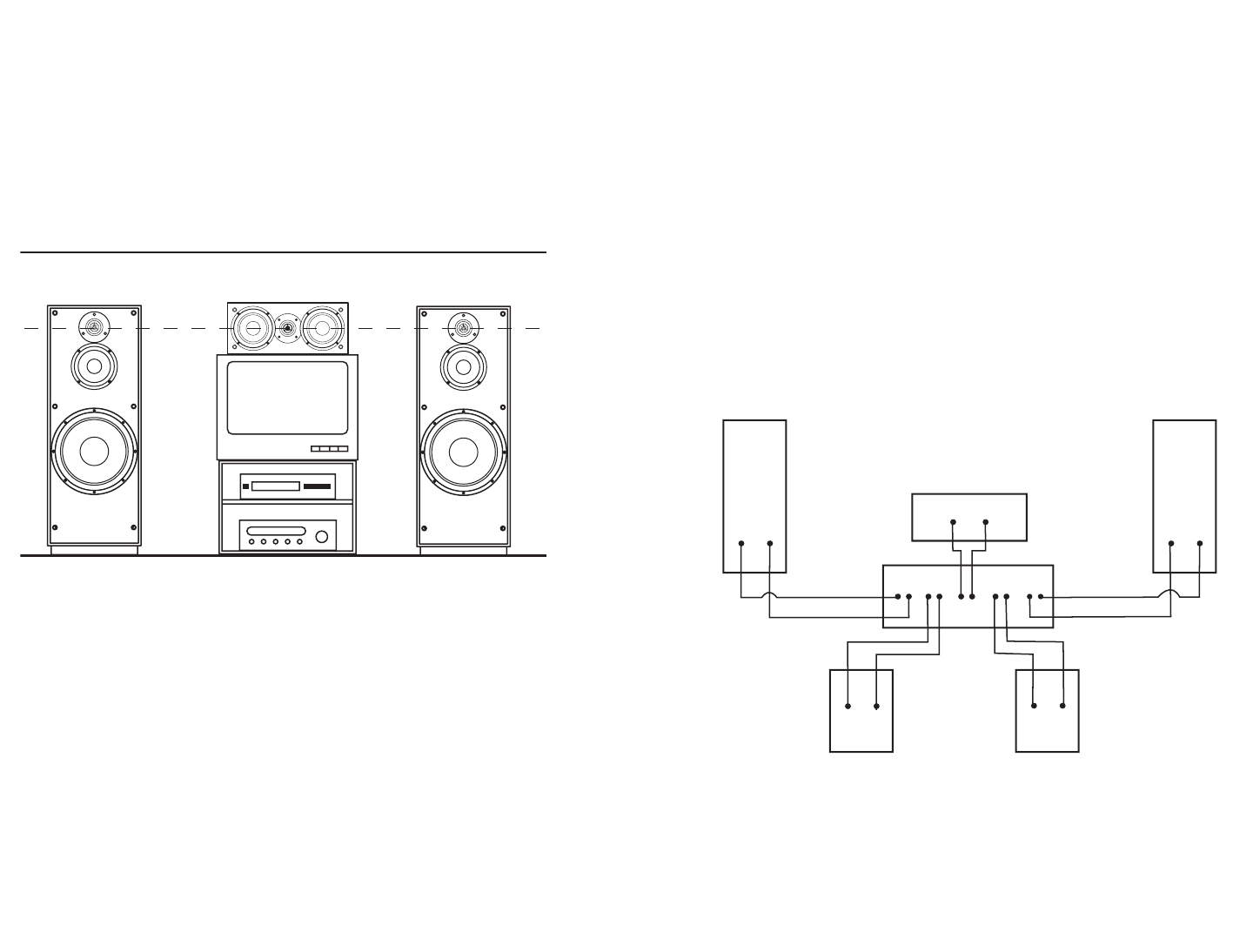
Place the center channel at an equal distance to the listening position as the main
speakers are. Also, place the height of the center channel’s tweeter as close to the
same height as the main speakers’ tweeters (Figure 3). This will prevent image
blurring when sounds are panned from the one side of the room to the other.
Figure 3 Proper Placement of Center Channel Speaker
Overload Protection
The FT10 and FT12 are equipped with an internal overload protection circuit. The
overload protection is a two-stage circuit designed to prevent accidental damage
caused by overpowering or amplifier clipping.
The first stage is an active compression circuit that protects the midrange and
tweeter. Music signals that may be harmful to the midrange or tweeter are com-
pressed. The result is a seamless, clear sounding loudspeaker.
The second stage is a PTC switch designed to protect the entire loudspeaker.
When the music signal reaches a harmful level or is distorting excessively the
PTC switches to a high impedance state, reducing the loudspeaker output dra-
matically. Turning the volume control down to a low level for 10 seconds will
restore normal operation.
HOOK UP
Note: If your amplifier or receiver has a 4/8Ω switch, optimum performance
will be achieved using the 4Ω or lowest impedance position.
Use 16 gauge or heavier speaker wire for connecting to your amplifier or receiver.
Cut wire lengths leaving an extra 12” to 24” at each end to allow for moving the
speaker or receiver.
Using a wire cutter or a sharp knife, strip 1/2” of insulation off each end of the wire
to expose the conductor. Twist wire ends to prevent from fraying. Connect the
conductors to the binding posts on the bottom or back of the speaker by unscrew-
ing the post enough to expose the hole in the terminal post. Slip the exposed
conductor in the hole and tighten the post. Repeat this step for connecting to your
amplifier or receiver. Refer to the owner’s manual supplied with your electronics
to assist with proper hook up.
Note: To ensure proper performance, make sure that the wire from the red
(+) terminal on the speaker is connected to the red (+) terminal on your
amplifier or receiver. Likewise, make sure the wire from the black (-) termi-
nal on the speaker is connected to the black (-) terminal on the amplifier or
receiver. (Figure 4)
+
-
REDBLACK
REDBLACK
REDBLACK
REDBLACK
REDBLACK
+
-
+
-
+
-+
-
FIGURE 4 Connecting Speakers to Amplifier or Receiver
Once your speakers are hooked up, turn on your electronics and test to make
sure they are functioning properly. If your speakers sound “thin” with little bass
and have a poor center image, one of the speaker wires is probably hooked up
backwards. Double check all connections for proper polarity.
