Decatur Electronics SI-3L Low profile directional radar unit User Manual
Decatur Electronics Inc Low profile directional radar unit Users Manual
Users Manual
User’s Manual
Rev 2/11/2013
SI-3L™
System Interface 3
Low Prole

SI-3L™
System Interface 3
Low Prole
User’s Manual
Table of Contents
Welcome .............................................................6
About This Manual ....................................................7
1 Safety Information ....................................................7
2 Receiving Inspection ..................................................8
3 Getting Started .......................................................9
3.1 Introduction......................................................9
3.2 Connecting The Serial Cable.......................................9
3.3 Optional Programming Cable . . . . . . . . . . . . . . . . . . . . . . . . . . . . . . . . . . . . 10
3.4 Mounting Conguration .........................................10
4 Conguring the SI-3L™ ...............................................11
4.1 Equipment Needed ..............................................11
4.2 Conguration Program Screen . . . . . . . . . . . . . . . . . . . . . . . . . . . . . . . . . . . 11
4.3 Conguration Items Screen ......................................14
4.3.1 Serial Number .................................................14
4.3.2 Unit ID ........................................................14
4.3.3 Measurement..................................................15
4.3.4 Target Report..................................................16
4.3.5 Target Select ..................................................17
4.3.6 Cosine Horizontal and Cosine Vertical . . . . . . . . . . . . . . . . . . . . . . . . . . 17
4.3.7 Hold Time .....................................................17
4.3.8 Update Rate...................................................18
4.3.9 Sensitivity .....................................................18
4.3.10 Alarm Speed Threshold .......................................19
4.3.11 Baud Rate ....................................................19
4.3.12 Serial Protocol . . . . . . . . . . . . . . . . . . . . . . . . . . . . . . . . . . . . . . . . . . . . . . . . 20
4.4 Select Program FILE to Load from MENU (Optional) . . . . . . . . . . . . . . . 20
4.5 Press CONFIGURE or PROGRAM CONFIGURE . . . . . . . . . . . . . . . . . . . . . . 20
4.5.1 Congure .....................................................21
4.5.2 Program and Congure ........................................21
4.6 Power Up SI Unit.................................................21
4.7 Congurtion Notes ..............................................21
5 Performance Tips ....................................................22
5.1 How Radar Works ................................................22
5.2 Interference Sources .............................................22
5.2.1 Angular Interference (Cosine Eect) . . . . . . . . . . . . . . . . . . . . . . . . . . . . 22
5.2.2 Fan Interference ...............................................24
5.2.3 Electromagnetic Interference (EMI) . . . . . . . . . . . . . . . . . . . . . . . . . . . . . 24
5.2.4 Feedback Interference .........................................24
5.2.5 Multi-Path Beam Cancellation . . . . . . . . . . . . . . . . . . . . . . . . . . . . . . . . . . 24
5.2.6 Radio Frequency Interference (RFI) . . . . . . . . . . . . . . . . . . . . . . . . . . . . . 24
5.2.7 Scanning . . . . . . . . . . . . . . . . . . . . . . . . . . . . . . . . . . . . . . . . . . . . . . . . . . . . . . 25
5.2.8 Environmental Factors: Wind, Rain, Snow . . . . . . . . . . . . . . . . . . . . . . . 25
6 Testing The Device ...................................................26
6.1 Tuning Fork Test .................................................26
7 Care, Cleaning, and Storage ..........................................27
8 Specications........................................................27
8.1 Antenna Parameters .............................................27
8.2 Environment ....................................................27
8.3 Speed Range Parameters ........................................27
8.4 Power Consumption ............................................27
9 Legal Requirements..................................................28
9.1 RF Exposure Compliance Statement. . . . . . . . . . . . . . . . . . . . . . . . . . . . . . 28
9.2 FCC Statement ..................................................28
9.3 Industry Canada .................................................28
10 Frequently Asked Questions (FAQ) . . . . . . . . . . . . . . . . . . . . . . . . . . . . . . . . . . . . 29
11 Warranty.............................................................29
12 Service Return Procedure.............................................30
13 How To Order Additional Products . . . . . . . . . . . . . . . . . . . . . . . . . . . . . . . . . . . . 31
14 User Notes...........................................................32

SI-3™ User’s Manual
6
Welcome To Decatur Electronics, Inc.!
Thank you for choosing this Decatur Electronics product—the
System Interface 3 Low Prole(SI-3L)™, a highly advanced, low prole
directional radar unit that will reward your department with years of
dependable service. The SI-3L™ incorporates high performance and
long range with many leading features. We urge you to study this
manual before using the SI-3L™ so you can maximize the benets
of this sophisticated radar device. We believe you will be pleasantly
surprised by the features and advantages.
If you are as pleased with its performance as we think you will be,
ask your Decatur sales representative about other Decatur products
including the Genesis™ line of radars, the Onsite™ line of speed
trailers, dollies, pole signs and the Responder™ line of in-car video
systems.
Try any one of our products and see if you don't agree that it is the
best-in-class!
—The Management and Sta at Decatur Electronics
SI-3™ User’s Manual
7
About This Manual
This manual contains valuable information to help you set up, use
and maintain your radar so you can optimize its life and keep it at
peak performance. Please take a moment to read through it, and
keep it handy for future reference.
Note the following symbols in this manual:
Indicates a warning message about safety
precautions. Please read it carefully.
Indicates a helpful tip or precaution to note.
1. Safety Information
All service needs should be referred back to the manufacturer.
WARNINGS
• Do not over voltage the radar - it can damage the unit!
• The SI-3L™ is designed to operate o of conventional
+12 VDC (+9 VDC to +24 VDC) from the serial cable.
Important Warnings
• Opening the SI-3L™ automatically voids any warranty
still in eect. There are no user serviceable parts inside.
• Do not expose the SI-3L™ to excessive moisture. Never
submerge the device.
• Do not drop the SI-3L™ on hard surfaces since damage
could occur. Units damaged by dropping or abuse are
not covered for warranty repair.
Violation of these guidelines may void the warranty.
SI-3™ User’s Manual
8
2. Receiving Inspection
When you receive your SI-3L™:
• Inspect it for any freight damage that might have happened
during shipping or unloading. Take pictures to document any
damage.
• Notify the freight company immediately of any damage,
preferably while the driver is present.
• Record the damage on the bill of lading and keep a record of the
problems or damage.
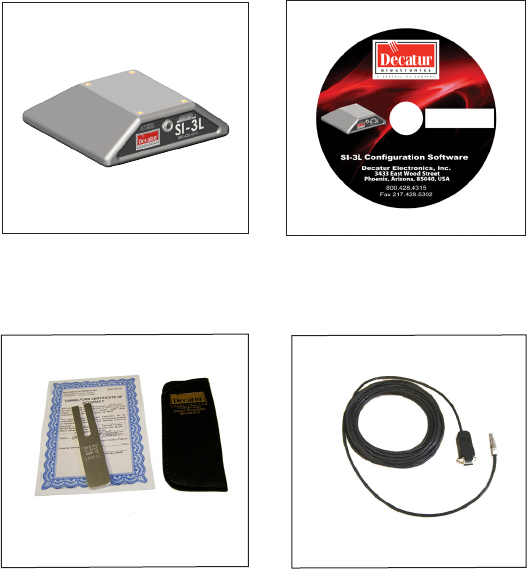
• The package should include the following pictured items along
with this User’s Manual.
SI-3L™ Programming Disk
S900-34
Tuning Fork
S769-78551-0
Serial cable
SI-3™ User’s Manual
9
3. Getting Started
3.1 Introduction
The SI-3L™ is a low prole radar specically designed to measure
speeds and export that speed information as RS232 data via the
special serial cable. This allows the SI-3L™ to be used for a wide
range of applications such as Radar Speed Trailers, trac speed
data collection (when used with the Decatur EZ Stat™ data logger)
or other uses where speed monitoring is desired. The SI-3L™ comes
with a Programming disk that allows the user to congure certain
parameters of the SI-3L™ for specic applications. Refer to Chapter 4
for conguration information. Additionally, a Radar Monitor program
is also available that allows you to display speed information on your
computer and record that information to a text le for analysis.
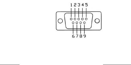
3.2 Connecting the Serial Cable
The SI-3L™ operates o of +12VDC and comes with a cable that
has two connectors. The circular connector plugs into the SI-3L™
and the DB-9 serial connector (shown in Figure 3.2) is used for
powering and communicating with the SI-3L. When connecting
the cable it is important to understand that unlike standard RS232
serial connectors that have no +12VDC provisions, the SI-3L's™ serial
connector has two pins dedicated to B+ and ground for the purpose
of powering the unit. Figure 3.2 shows the pin arrangement.
Figure 3.2
Front view SI-3™ Serial Connector
Top Row Bottom Row
Pin 1 = +12VDC (power) Pin 6 = N/C
Pin 2 = RS232 TX Pin 7 = N/C
Pin 3 = RS232 RX Pin 8 = Remote On
Pin 4 = N/C Pin 9 = Ground (power)
Pin 5 = RS232 Ground
SI-3™ User’s Manual
10
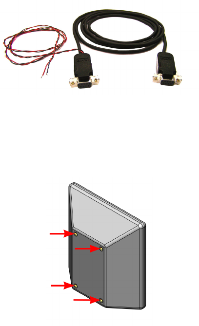
3.3 Optional Programming Cable
For conguring and testing purposes a programming cable is
available. The cable is designed with two DB-9 connectors and
a black and red wire for supplying B+ and ground to the SI-3L™.
One end of the cable plugs into the serial port of a computer and
the other end into the SI-3L™. The same end that plugs into the
SI-3L™ has a red wire that is connected to +12 VDC and a black
wire that is connected to ground. A regulated power supply can
be used to supply the +12 VDC. Once the programming software
is installed on the computer then the SI-3L™ can be accessed and
parameters changed to meet your application. Refer to Chapter 4 for
programming information.
Figure 3.3
S769-127-0
Optional Programming Cable
3.4 Mounting Conguration
The SI-3L™ comes equipped with four mounting holes on the reverse
side (See Figure 3.4). Use these holes only to mount the SI-3L™ .
Figure 3.4
Mounting hole locations
SI-3™ User’s Manual
11
4. Configuring the SI-3L™
Before proceeding make sure your computer has Microsoft® Net
Framework Version 4.0™ installed. If not, you can install it by going to:
http://msdn.microsoft.com/en-us/netframework/aa569263.aspx.
4.1 Equipment Needed
• SI-3L™ radar device
• SI-3L™ Programming cable (S769-127-0)
• PC with either a usable RS232 serial port or a USB-to-RS232
adapter.
• RS232 cable to connect between the Power and
Communications adapter and the PC (if needed). This cable is a
9-pin RS232 cable with a male connector on one end and female
connector on the other.
• SI-3L™ conguration CD (S785-1-0)
• 12V power supply
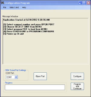
4.2 Conguration Program Screen
1. Apply 12VDC power to the SI-3L™ through the programming
cable. Open and run the SI-3L™ Cong 4 (conguration) program;
which is shown in Figure 4.2a.
Figure 4.2a
Conguration Program screen
SI-3™ User’s Manual
12
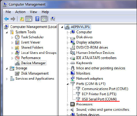
2. The SI-3L™ is designed to be connected to the computer's serial
port. If you do not have a serial port and are using a USB to
Serial adapter make sure the adapter has been installed per the
instructions that came with it. Next, connect the SI-3L™ to the
computer through the adapter and check the Device Manager/
Ports. The port assignment will appear as "USB Serial Port". Note
the port assignment. The example in Figure 4.2b shows that Port
4 has been assigned. Your port assignment may be dierent and
the port assignment can change the next time the USB to Serial
adapter is plugged in.
Figure 4.2b
Device Manager screen
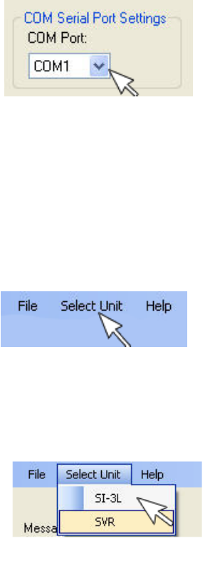
3. From the Conguration Program/Com Serial Port Settings screen
(Figure 4.2c) click on the down arrow and select the COM port
that your PC has assigned. If you are connecting through the
computer's serial port, it will normally be "Com 1" or "Com 2". If
you are using the USB to Serial adapter, use the port shown in
Device Manager/Ports.
SI-3™ User’s Manual
13
Figure 4.2c
Front view SI-3™ Serial Connector
4. Once the COM port has been selected, left click on the "Open
Port" button. A "COM port OPEN" message will be displayed
indicating that the COM port is now active.
5. Next, go to the top of the Conguration Program Screen and
click on the "Select Unit" tab of the tool bar (Figure 4.2d)
Figure 4.2d
Click on the Select Unit tab
6. When the tab opens select "SI-3L".
Figure 4.2e
Select SI-3L
SI-3™ User’s Manual
14
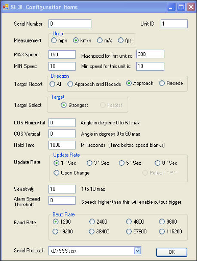
4.3 Conguration Items Screen
Once "SI-3L" has been selected the "SI-3L Conguration Items"
screen will be displayed as shown Figure 4.3.
Figure 4.3
Conguration Items screen
The "SI-3L Conguration Items" screen allows for the setting of
several dierent parameters so that you can tailor the SI-3L™ to your
application. An explanation of each setting starting at the top of the
conguration screen follows:
4.3.1 Serial Number
Enter the serial number that is on the serial tag of your SI-3L™. Use
only the numbers and ignore any preceding letters.
4.3.2 Unit ID
The ID number of the radar device. In the case of the SI-3L™ the
Unit ID is "1".
SI-3™ User’s Manual
15
4.3.3 Measurement
Select the speed format that the SI-3L™ is to use.
• Miles-per-hour - Select "mph"
• Kilometers-per-hour - Select "km/h"
• Meters-per-second - Select "m/s"
• Feet-per-second - Select "fps"
The maximum and minimum speed range for each of the speed
formats will be displayed in the "Max speed for this unit is:" and
the "Min speed for this unit is" windows. The speed ranges for the
various selections are:
• For"mph" the speed range is 15-205 mph
• For "km/h" the speed range is 10-330 km/h
• For "m/s" the speed range is 3-90 m/s
• For "fps" the speed range is 10-300 fps
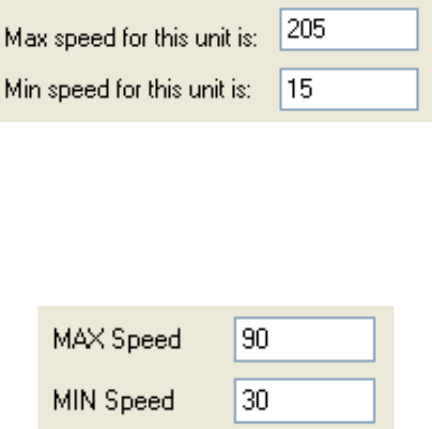
As an example, Figure 4.3.3a shows the speed range when the
"mph" speed format is selected.
Figure 4.3.3a
Speed range for mph
The speed range can be adjusted within those ranges by changing
the speed readings that appear in the "MAX Speed" and "MIN
Speed" windows (See Figure 4.3.3b). No vehicles will be reported
outside the minimum and maximum congured speeds
Figure 4.3.3b
Set the speed range you want to use

SI-3™ User’s Manual
16
As an example, when "mph" is selected the minimum and
maximum speeds that can be processed are 15 to 205 mph
respectively. However, if the SI-3L™ is going to be used in an
application where any speed above 90 mph is to be ignored, then
the "MAX Speed" window can be changed to 90 and no speed
above 90 will then be processed. Likewise, if the SI-3L™ is to be
used where no speeds below 30 mph need to be considered then
setting the "MIN Speed" to 30 will cause the SI-3L™ to not report any
speeds below 30 mph.
4.3.4 Target Report
The "Target Report" has four selections and allows you to set the
direction reporting of the SI-3L™.
All - Tracks the strongest overall target signal regardless of
direction.
• Approach and Recede - Tracks the strongest true directional
target coming towards or going away from the SI-3L™. This
mode contains directional ltering that will lter out any signal
that doesn't have a good directional signal.
• Approach - Tracks the strongest true directional target coming
towards the SI-3L™. This mode contains directional ltering
that will lter out any signal that does not have a good
directional signal.
• Recede - Tracks the strongest true directional target going
away from the SI-3L™. This mode contains directional ltering
that will lter out any signal that does not have a good
directional signal.
Figure 4.3.4
Target Report
SI-3™ User’s Manual
17
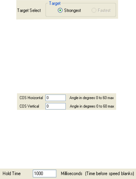
4.3.5 Target Select
Currently not selectable. A Target Select value of “Strong” is the
standard SI-3L™ conguration.
Figure 4.3.5
Target Select
4.3.6 Cosine Horizontal and Cosine Vertical
For bridge-type installations where the SI-3L™ is over the trac
and pointing slightly down, the vertical angle can be entered here
to ensure that the SI-3L™ calculates the correct vehicle speeds.
For installations where the SI-3L™ is at a signicant angle from the
road, the horizontal angle can also be congured. These two may
be used together. Keep the angles between 0 and 45 degrees for
maximum accuracy. Default is "0".
Figure 4.3.6
Cosine settings
4.3.7 Hold Time
The "Hold Time" value indicates the length of time in milliseconds
the vehicle speed is displayed after the vehicle moves out of range.
The default "Hold Time" is 1000 milliseconds.
Figure 4.3.7
Hold Time
SI-3™ User’s Manual
18
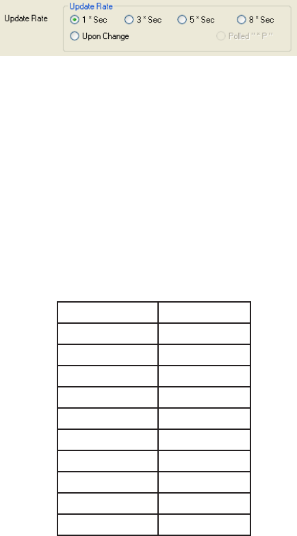
4.3.8 Update Rate
The selected speed format will be sent in whatever time interval
(in milliseconds) that you set. The "Update Rate" can be as low as 20
milliseconds. The number should be a multiple of 20 milliseconds.
The "Update Rate" and the amount of serial port activity do not
aect the measurement accuracy of the SI-3L™. The default rate is 1
Second.
Figure 4.3.8
Update Rate
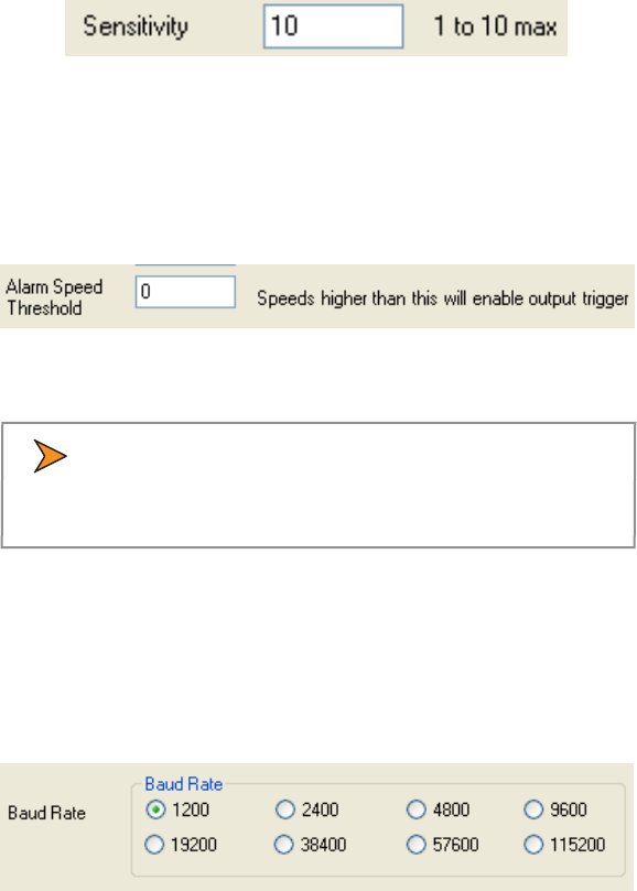
4.3.9 Sensitivity
The SI-3L™ has a sensitivity range of 1-10 and is shipped with the
range setting at the (10) maximum (See Figure 4.3.9). The sensitivity
can be decreased for closer range if needed. When changing the
"Sensitivity" remember that if the setting is too low the SI-3L™ may
take too long to lock onto and display a speed and if too high it
may lock onto distant targets that are undesired.
Typical ranges for an on-coming mid-sized sedan are:
Setting Range (feet)
1 350
2 575
3 800
4 950
5 1300
6 1700
7 1875
8 2400
9 2800
10 >3000
SI-3™ User’s Manual
19
The distances will vary based on location, body of the car and
alignment of the antenna. It is normal for the range to vary by 10%
on identical cars.
Figure 4.3.9
Sensitivity Setting
4.3.10 Alarm Speed Threshold
When the target speed is greater than the "Alarm Speed Threshold"
setting the ouput line will go low (open collector output).
Figure 4.3.10
Alarm Speed Threshold
• Maximum source current for the open collector output
is 50 mA. Exceeding the 50 mA limit can damage the
SI-3L™.
4.3.11 Baud Rate
The "Baud Rate" can be 1200, 2400, 4800, 9600, 19200, 38400,
57600, or 115200 bits per second. The SI-3L™ always uses 8 bits, no
parity, and one stop bit for its serial port conguration. The default
baud rate is 1200.
Figure 4.3.11
Baud Rate
SI-3™ User’s Manual
20
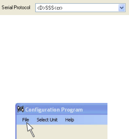
4.3.12 Serial Protocol
Currently there is only one protocol available. <D> is a direction
character that is “+” for vehicles coming towards the sign, “-“ for
vehicles moving away, and “?” when the direction cannot be
determined. [S] represents the displayed speed. If a period is within
the square brackets it is the decimal point. Any zeros are sent as
described and do not change with a vehicle’s speed. The <cr>
signies the end of the outgoing message.
Figure 4.3.12
Serial Protocol
4.4 Select Program FILE to Load from MENU (Optional)
From time to time Decatur Electronics will release new rmware for
the SI-3L™ . If you have received new rmware then save the rmware
to a le on your hard drive remembering the path to where the le is
saved.
If you have new rmware and need to congure the rmware to the
SI-3L™ then click on the "File" tab at the top of the screen.
Figure 4.4
Click on the "File" tab
From "File" go to where you have saved the new rmware and click
on the le. Next, proceed to Section 4.5.
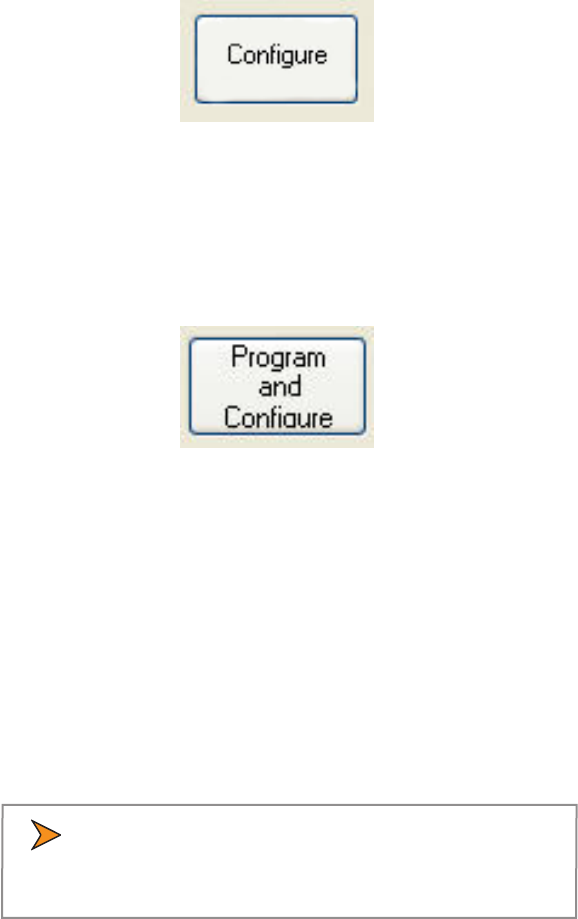
4.5 Press CONFIGURE or PROGRAM-CONFIGURE
Two options are available. You can either congure the SI-3L™ to
only accept the changes you have made to the "SI-3L Conguration
Items" screen (Figure 4.3a) or you can congure the SI-3L™ to accept
the changes you have made to the "SI-3L Conguration Items screen"
and to also accept the new rmware.
SI-3™ User’s Manual
21
4.5.1 Congure
Select the "Congure" button if you want to only have the SI-
3L™ accept the changes that have been made to the "SI-3L
Conguration Items" screen.
Figure 4.5.1
Congure Only button
4.5.2 Program and Congure
Select the "Program and Congure" button if you want the SI-
3L™ to accept the changes that have been made to the "SI-3L
Conguration Items" screen and to program the SI-3L™ with new
rmware.
Figure 4.5.1
Program and Congure button
4.6 Power Up SI Unit
Once all selections have been made and the proper conguration
button has been pressed, power up the SI-3L™ . Once powered
and properly connected the SI-3L™ will accept the updated
programming.
4.7 Conguration Notes
All changes occur immediately and do not require a reboot of the SI-
3L™ to become operational.
• Please wait 2 seconds after the last conguration
command before disconnecting the power to allow the
SI-3L™ to record the setting in ash memory.
SI-3™ User’s Manual
22
5. Performance Tips
Understanding potential radar interference and what to do when it
occurs can greatly increase the radar’s performance.
5.1 How Radar Works
Determining an object’s speed begins with the radar transmitting
a beam of microwave energy (radio waves) at an approaching or
departing target. When energy from this beam strikes a target, a
small amount of the beam is reected back to the antenna. The
reected signal frequency shifts by an amount proportional to the
speed of the target. This is known as the Doppler eect. The radar
device then determines the target speed from the dierence in
frequency between the reected and transmitted signal.
5.2 Interference Sources
When properly installed and operated, Doppler radar technology
is extremely accurate and reliable. However, variations in the
environment can cause situations and circumstances which can
cause spurious (erratic and unusually low or high) speeds to
display. Signs that a speed is spurious can include the following
characteristics:
• A reading appears when no target is in the operational range of
the antenna.
• A target entering the operational range overrides the
interference signal, causing the display speed to change
suddenly to the target’s speed.
• Speeds are irregular.
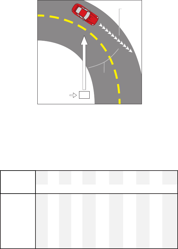
5.2.1 Angular Interference (Cosine Eect)
The cosine eect causes the system to display a speed which is
lower than the actual target speed. This condition occurs when
the target’s path is not parallel to the antenna such as the target
vehicle traveling on a curve or hill.
SI-3™ User’s Manual
23
As the angle between the beam of the antenna and the target
increases, the displayed speed decreases. Ideally, an angle of zero
(0) degrees is preferable, because the displayed speed is the actual
target speed. However, in all uses of police radar, the radar device is
always at a slight angle to the target vehicle to avoid collisions.
Velocity
Vector
Angle
Radar
Figure 5.2.1
An angle between the antenna and the
target causes the cosine eect
The following table shows the eect that an increasing angle has
on a displayed speed.
Horizontal Angle Degrees
Actual
Speed
0° 1° 3° 5° 10° 15° 20° 30° 45° 60° 90°
Displayed speed:
30 mph 30 29 29 29 29 28 28 26 21 15 0
40 mph 40 39 39 39 39 38 37 34 28 20 0
50 mph 50 49 49 49 49 48 46 43 35 25 0
60 mph 60 59 59 59 59 57 56 51 31 30 0
70 mph 70 69 69 69 68 67 65 60 49 35 0
80 mph 80 79 79 79 78 77 75 69 57 40 0
Table 5.2.1
Actual and displayed speeds at antenna-to-target angles
SI-3™ User’s Manual
24
Small angles (less than 10°) have little eect on accuracy. As the
angle increases, the displayed speed decreases. At 90°, the target
speed is 0—grossly incorrect.
5.2.2 Fan Interference
Fan interference is one of the most common forms of interference
that you are likely to experience. It is caused when the radar
measures the speed of a blower fan that is within the beam path of
the radar. If the SI-3L™ is used inside of a building keep in mind that
furnace and air conditioner fans can cause interference. To correct
this, relocate the radar so it does not display spurious speeds or
turn o the fan motor.
5.2.3 Electromagnetic Interference (EMI)
Operating electric motors can produce EMI. EMI from power seats
or windshield wipers can also produce spurious target speeds. To
correct the interference, simply turn o its source.
5.2.4 Feedback Interference
When the radar beam is directed at computer screens, streetlights,
and other electronic devices it can display spurious speeds.
Relocate the SI-3L™ to avoid the interference.
5.2.5 Multi-Path Beam Cancellation
If multi-path beam cancellation occurs, the target vehicle speed
sporadically blinks and reappears at semi-random intervals. This
type of interference occurs when the radar loses track of a target
because the target is reecting two or more signals which are
interfering with each other. The SI-3L™ is immune from multi-path
cancellation.
5.2.6 Radio Frequency Interference (RFI)
The system can inadvertently process radio energy as Doppler
speeds including that from 2-way radios, airport radar, microwave
transmission towers, CB radio transmitters, and AM/FM
transmission towers. For this type of interference to occur, the SI-
3L™ must be operating very close to the radio transmitter.
SI-3™ User’s Manual
25
5.2.7 Scanning
The SI-3L™ is designed to be used while attached to a solid mount
position. Moving or “scanning” the antenna past stationary objects
can cause the system to detect motion. Obtaining a speed reading
from scanning will not happen as long as the antenna is held in
one position and is not moved.
5.2.8 Environmental Factors: Rain & Snow
Environmental factors such as rain or snow can reduce the distance
at which a target can be detected; however, these factors will not
aect accuracy.
SI-3™ User’s Manual
26
6. Testing the Device
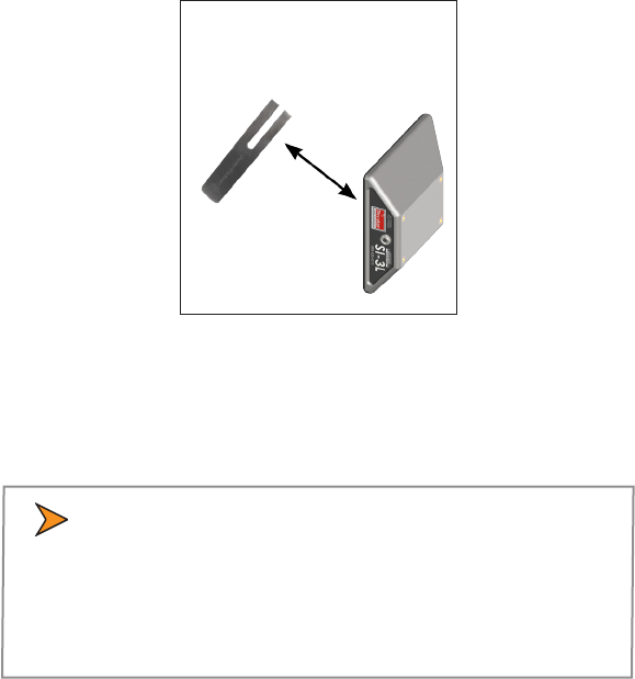
6.1 Tuning Fork Test
You can verify signal processing accuracy by using a tuning fork,
which comes with the radar. There is a one minute time window
from when the SI-3L™ is rst powered on in which you can test the
unit using a tuning fork. After one minute the SI-3L™ switches to
directional mode and the fork will no longer be read.
To begin the test, tap the tines of the fork on a rm, non-metallic
surface. The tuning fork will ring audibly. Place the tuning fork that
you tapped with the narrow side facing about 3 inches directly in
front of the antenna. Compare the speed in the display window to
the speed stamped on the fork. If the dierence is within ±1 display
unit, the SI-3L™ is working properly.
Figure 6.1
Place the vibrating tuning fork about 3 inches in front of the antenna
If the device does not display the expected speed, contact Decatur
Electronics Customer Service at 888.428.4315 to arrange for service.
• Only tap the tuning fork against hard plastic, wood,
and materials that are softer than metal. Repeatedly
tapping the tines on hard surfaces, such as metal and
concrete, can damage the tines and invalidate the fork
for future tests.
SI-3™ User’s Manual
27
7. Care, Cleaning, and Storage
• Avoid spilling food, beverages, and other liquids and substances
on the radar device
• When you are not using or transporting the device, store it in its
original packaging
• To clean use a soft clean cloth which is free of cleaning solutions
8. Specifications
8.1 Antenna Parameters
K-Band
Transmission frequency 24.000 - 24.250 GHz
(24.150 GHz nominal)
Beamwidth 6.5° x 5.5º @ -3dB point
Polarization Linear
Output power (EIRP) +20 dBm
Power Density 114.3 dBuV/m at 3 metres
Horizontal Sidelobe Suppression 15 dB typical
Vertical Sidelobe Suppression 15 dB typical
8.2 Environment
Ambient operating temperatures -22ºF to +158ºF
(-30ºC to +70ºC)
Maximum humidity 100% relative humidity
(Unit is weather proof,
not water proof)
8.3 Speed Range Parameters
Speed Display Ranges Minimum Maximum
mph option 5 150
km/h option 8 241
fps option 10 300
m/s 3 90
8.4 Power Consumption Parameters
Supply voltage range +9VDC to +24VDC
Nominal Current Draw 150 mA at +12VDC
SI-3™ User’s Manual
28
9. Legal Requirements
9.1 RF Exposure Compliance
The antenna used for this transmitter must be installed to provide a
separation distance of at least 20 cm from all persons and must not
be co-located or operating in conjunction with any other antenna
or transmitter. Users and installers must be provided with antenna
installation instructions and transmitter operating conditions for
satisfying RF exposure compliance.
9.2 FCC Statement
This device complies with FCC part 15 standard. Operation is subject
to the following two conditions:
1. This device may not cause interference, and
2. This device must accept any interference, including interference
that may cause undesired operation of the device.
Changes or modications not expressly approved by the party
responsible for compliance could void the user's authority to operate
the equipment.
9.3 Industry Canada
English Statement
This Category II radiocommunication device complies with Industry
Canada Standard RSS-310
French Statement
Ce dispositif de radiocommunication de catégorie II respecte la
norme CNR-310 d'Industrie Canada.
SI-3™ User’s Manual
29
10. Frequently Asked Questions (FAQ)
Q. My SI-3L™ has poor range. How can I remedy this?
A. Verify that the antenna has no obstructions in front of it. If the
unit still has poor range, increase the sensitivity level. If you still
have this problem, contact Decatur Electronics.
Q. What if I drop my SI-3L™?
A. The unit is extremely durable. Simply power up and perform
tuning fork test. If the unit doesn’t appear to work properly,
contact Decatur Electronics.
11. Warranty
ONE-YEAR RADAR WARRANTY
Decatur Electronics, Inc. guarantees the SI-3L™ to be free from
defects in workmanship and material and to operate within
specications for a period of one year. During this period, Decatur
Electronics will repair or replace, at its option, any component found
to be defective, without cost to the owner, providing you return the
part to the factory or to a Decatur authorized warranty service center.
The full warranty on parts and workmanship does not include normal
wear and tear, crushing, dropping, re, impact, immersion, misuse,
vandalism, or damage from attempted repair or modications by
unauthorized service agents or improper voltage.
For repairs, simply return the SI-3L™ directly to the factory or to a
Decatur authorized service center.
Refer to the instructions in the Service Return Procedure.
SI-3™ User’s Manual
30
12. Service Return Procedure
If you have questions, want a quick problem diagnosis, or need to
return your unit to the factory:
• Call Decatur Electronics and ask to speak with a Customer
Service Representative.
Phone: 888.428.4315
• Ask for a Return Authorization Number.
• Based on the information that you provide, the Customer Service
Representative will issue you a return authorization (RA) number.
Write the RA number on your note and shipping label.
• If so directed, include a note describing the problem and/or the
incident that resulted in the problem. Failure to do so can delay
the return of your system.
• Return the system to:
Decatur Electronics, Inc.
3433 East Wood Street
Phoenix, AZ, 85040, USA
RA # XXXXXX
Decatur Electronics does not accept items shipped COD. The
customer is responsible for all shipping charges to the Decatur
service location.
On warranty items Decatur Electronics will pay the freight (up to $10
US) for shipping the system from the repair facility to the customer.
We will charge the customer for any shipping charges above the
initial $10. If you want to ship your package express or next day air
we will send you an invoice for these freight charges.
After your product has been received, our technicians will investigate
the problem. If your SI-3L™ is out of warranty , you will be sent an
estimate of cost, prior to any repair work being performed. After
receiving the estimate, you can choose from the following options:
SI-3™ User’s Manual
31
1. Approve the estimate and proceed with repair.
2. Decline the estimate, and pay an estimate fee and return
shipping.
3. Decline the estimate and allow Decatur to recycle the unit, all
fees are waived.
If we do not hear back from within 30 days, then we will proceed with
option 3.
If your product is under warranty it will automatically be repaired and
sent back to you.
13. How to Order Additional Products
You can order upgrades and additional products for the SI-3L™
(when available). To see product descriptions or order products, see
the Decatur Electronics Web site at www.DecaturElectronics.com or
call the sales oce at 888.428.4315.
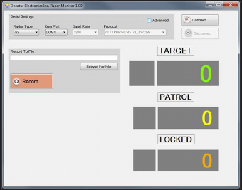
Radar Monitor
The optional Radar Monitor program is designed to display speed
information on a computer and record that information to a text le
for analysis. The program has been design to work specically with
the SI-3L™. For more information on the Radar Monitor contact the
sales oces at Decatur Electronics.
Figure 13
Radar Monitor Screen
SI-3™ User’s Manual
32
14. User Notes

www.DecaturElectronics.com
3433 East Wood Street, Phoenix, Arizona 85040, USA
800.428.4315 | 217.428.4315 | Fax 217.428.5302