Decatur Electronics SI3 Traffic/Speed Radar User Manual manual
Decatur Electronics Inc Traffic/Speed Radar manual
UserManual.wiki
>
Decatur Electronics
>
SI3 User Manual
manual
Navigation menu
Upload a User Manual
Namespaces
Wiki Guide
HTML
PDF
Info
Views
User Manual
Discussion / Help
Navigation
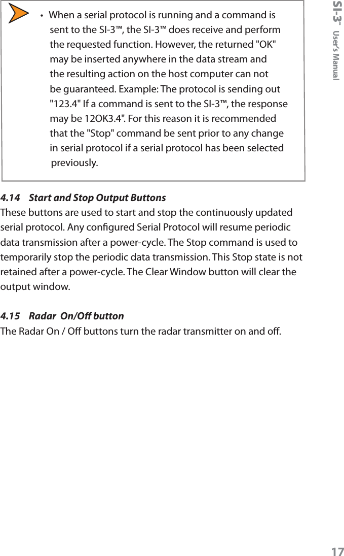
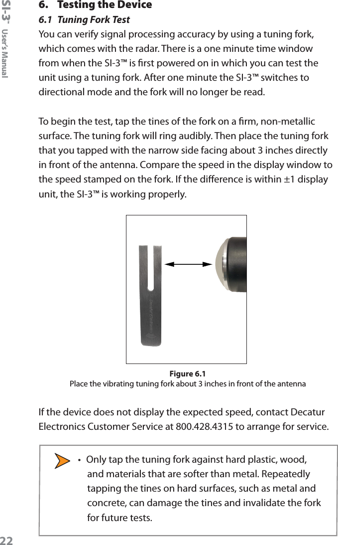
![SI-3™ User’s Manual16Typical ranges for an on-coming mid-sized sedan are:Setting Range (feet)1 3502 5753 8004 9505 13006 17007 18758 24009 280010 >3000The distances will vary based on location, body of the car and alignment of the antenna. It is normal for the range to vary by 10% on identical cars.4.13 Serial Protocol Refer to the product manual for more information on which protocol to use. <D> is a direction character that is “+” for vehicles coming towards the sign, “-“ for vehicles moving away, and “?” when the direction cannot be determined. [S] represents the displayed speed. If a period is within the square brackets it is the decimal point. Any zeros are sent as described and do not change with a vehicle’s speed. The <cr> signies the end of the outgoing message. The default setting is <D>[SSS.]<cr>. Other protocols listed are used by Decatur for testing purposes. Zero SuppressWhen this value is selected the SI-3™ will not send any information over the RS232 port unless a vehicle is detected.](https://usermanual.wiki/Decatur-Electronics/SI3/User-Guide-2039018-Page-16.png)