Deere and ISG Electronic Systems JDRFID RFID Reader User Manual
Phoenix International Corporation RFID Reader
UserManual.wiki
>
Deere and ISG Electronic Systems
>
JDRFID User Manual
user manual
Navigation menu
Upload a User Manual
Namespaces
Wiki Guide
HTML
PDF
Info
Views
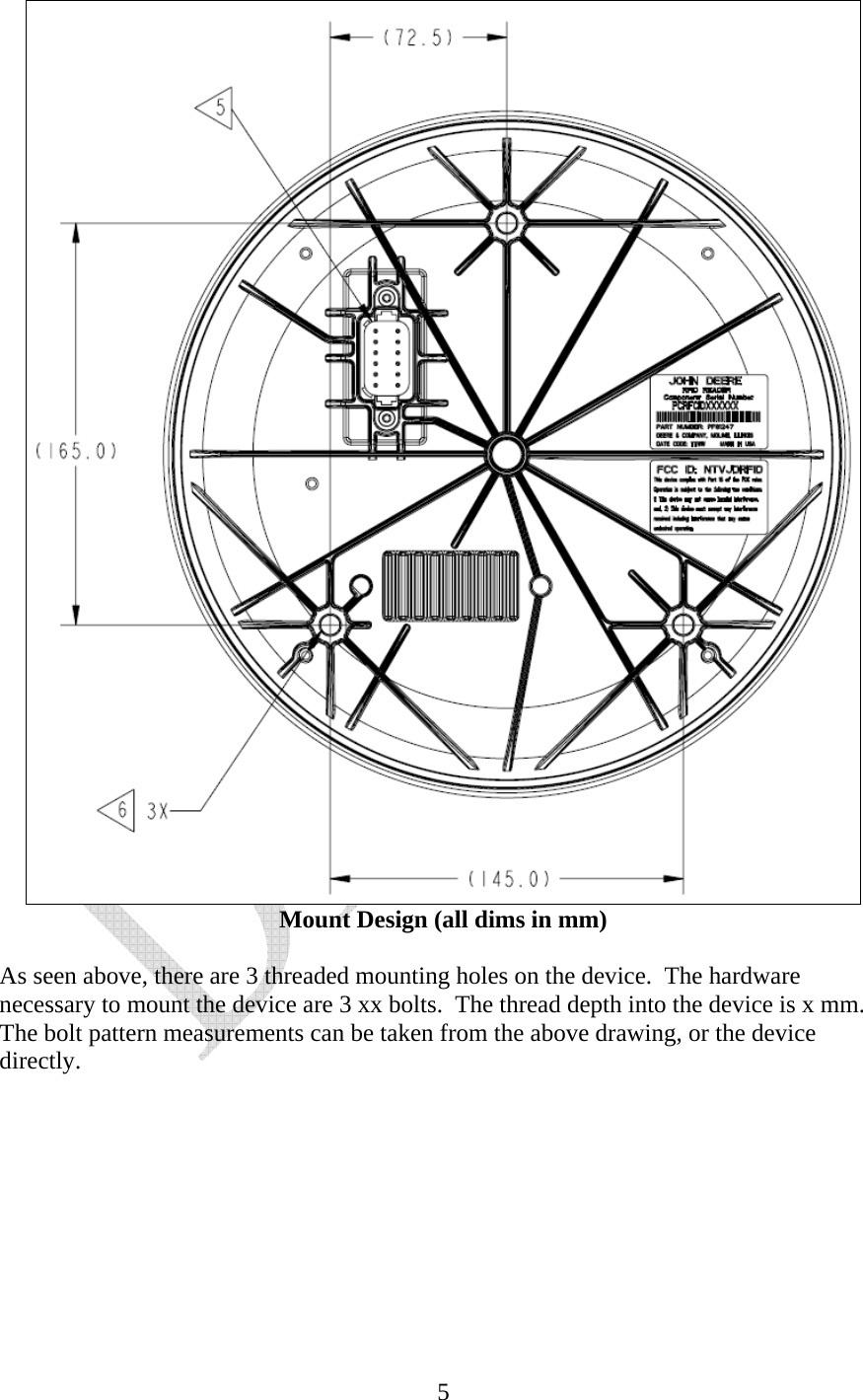
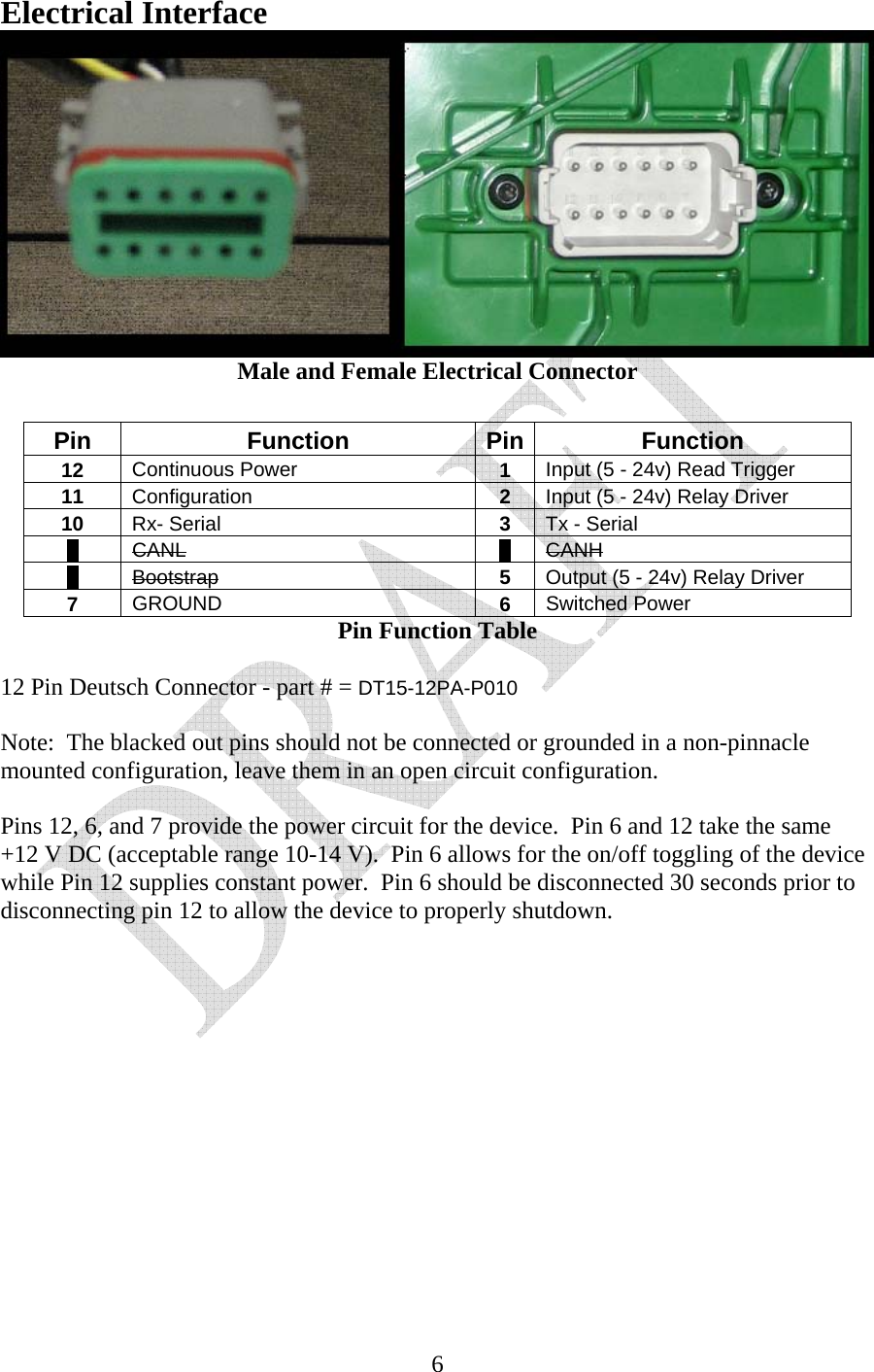
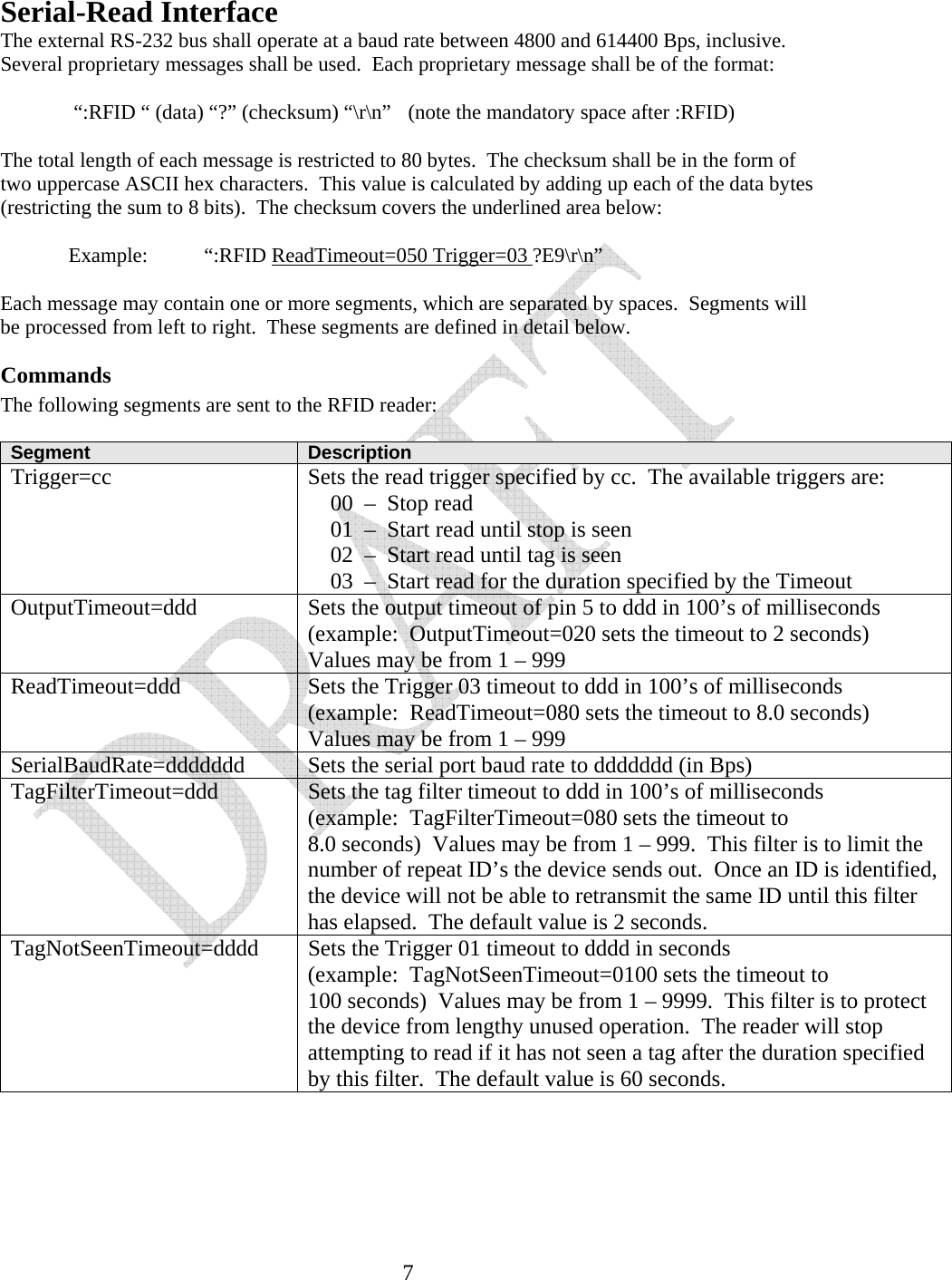
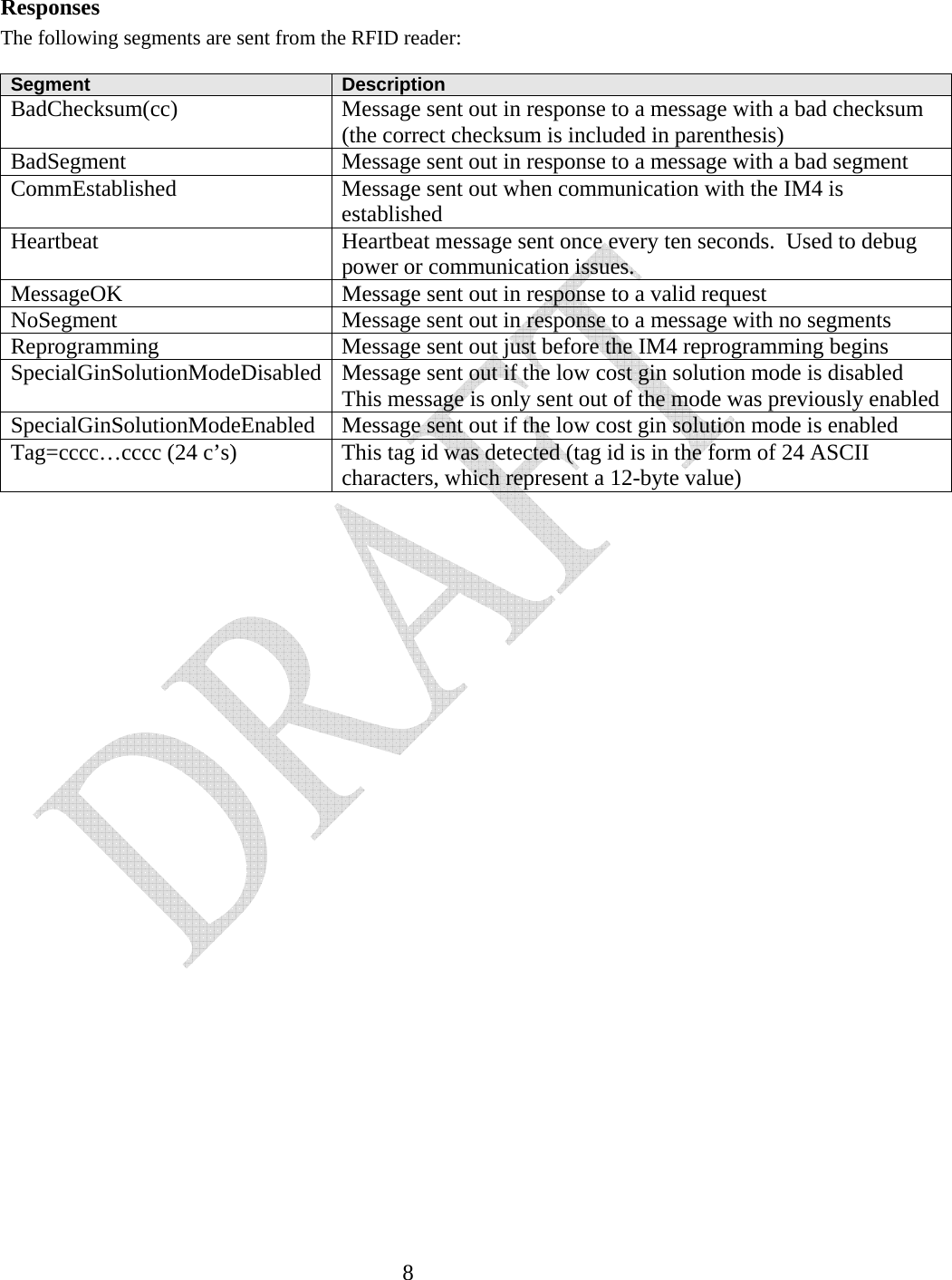
User Manual
Discussion / Help
Navigation