Deere and John Deere Intelligent Solutions Group PCSRAMP450A UHF 450 - 470 MHz RTK Amplifier User Manual Info
Deere & Company dba John Deere Intelligent Solutions Group UHF 450 - 470 MHz RTK Amplifier Users Manual Info
UserManual.wiki
>
Deere and John Deere Intelligent Solutions Group
>
PCSRAMP450A User Manual
Users Manual Info
Navigation menu
Upload a User Manual
Namespaces
Wiki Guide
HTML
PDF
Info
Views
User Manual
Discussion / Help
Navigation
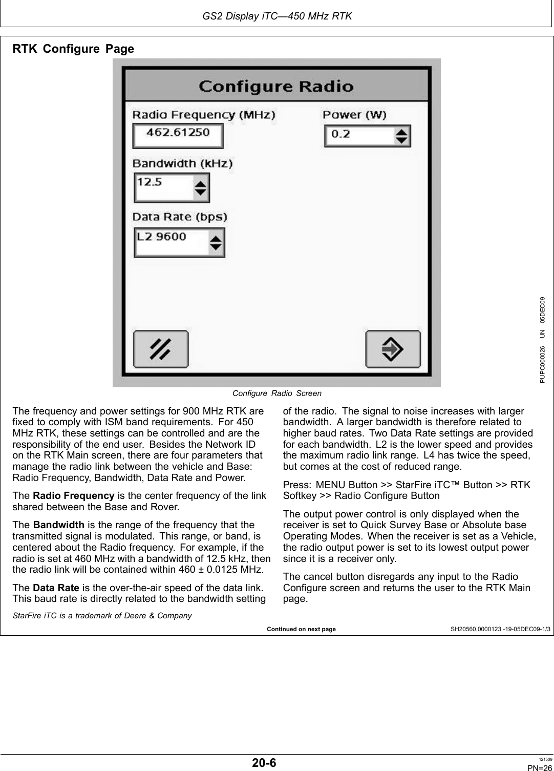
![ 0+] 57.23(5$725¶6 0$18$/ 0+] 57.203)3 ,668( $ (1*/,6+&$/,)251,$3URSRVLWLRQ :DUQLQJ'LHVHO HQJLQH H[KDXVW DQG VRPH RI LWV FRQVWLWXHQWVDUH NQRZQ WR WKH 6WDWH RI &DOLIRUQLD WR FDXVH FDQFHUELUWK GHIHFWV DQG RWKHU UHSURGXFWLYH KDUP,I WKLV SURGXFW FRQWDLQV D JDVROLQH HQJLQH:$51,1*7KH HQJLQH H[KDXVW IURP WKLV SURGXFW FRQWDLQVFKHPLFDOV NQRZQ WR WKH 6WDWH RI &DOLIRUQLD WR FDXVHFDQFHU ELUWK GHIHFWV RU RWKHU UHSURGXFWLYH KDUP7KH 6WDWH RI &DOLIRUQLD UHTXLUHV WKH DERYH WZR ZDUQLQJV-RKQ 'HHUH $J 0DQDJHPHQW 6ROXWLRQV1RUWK $PHULFDQ 9HUVLRQ35,17(' ,1 7+( 86$DCYOMPFP10070](https://usermanual.wiki/Deere-and-John-Deere-Intelligent-Solutions-Group/PCSRAMP450A/User-Guide-1303143-Page-1.png)


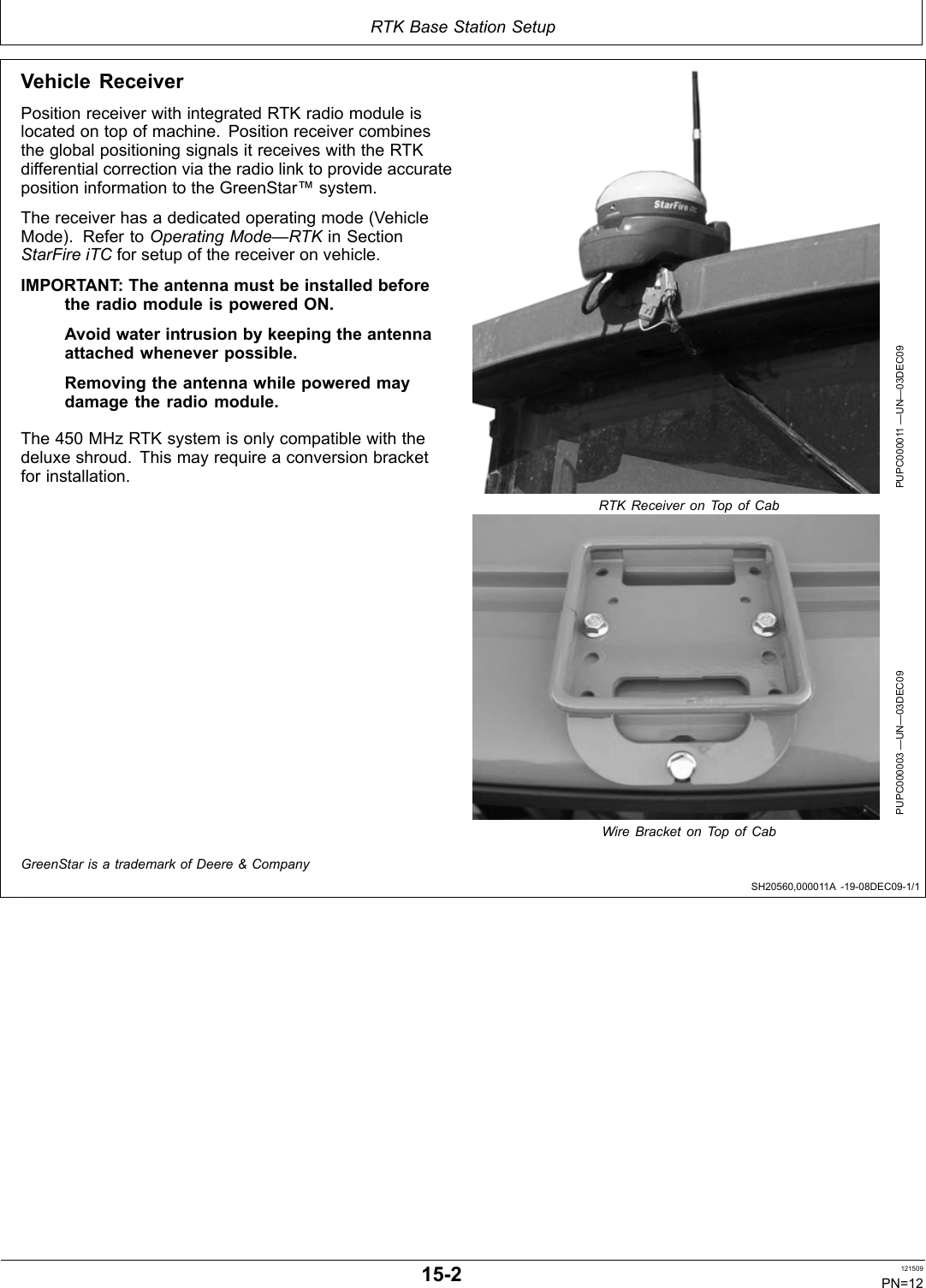
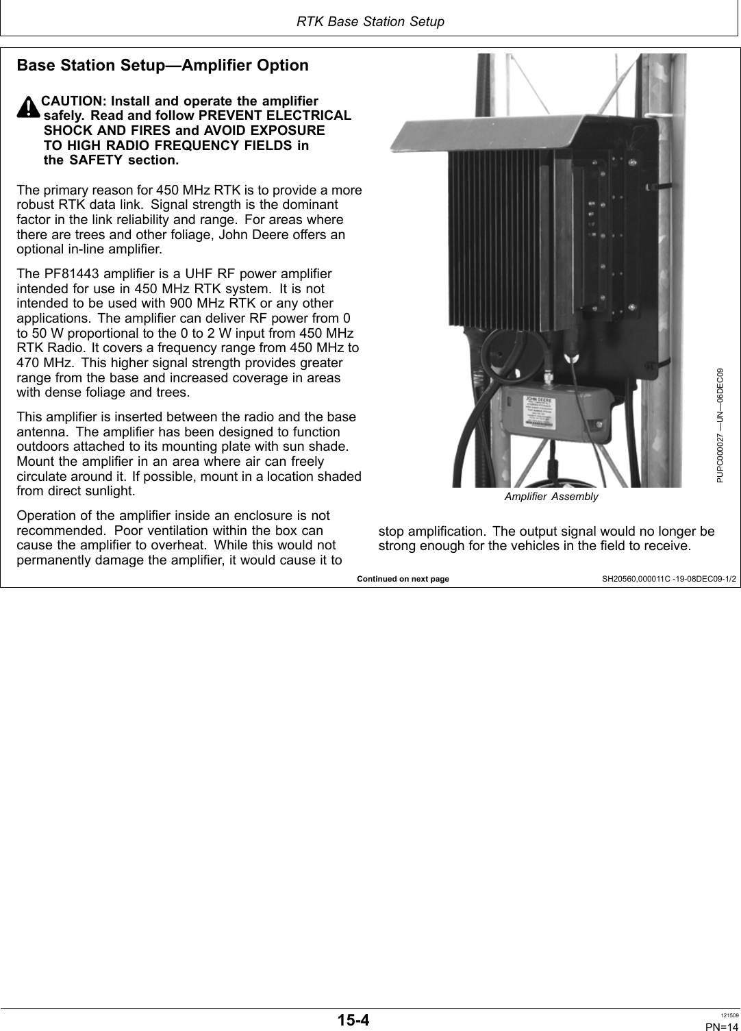
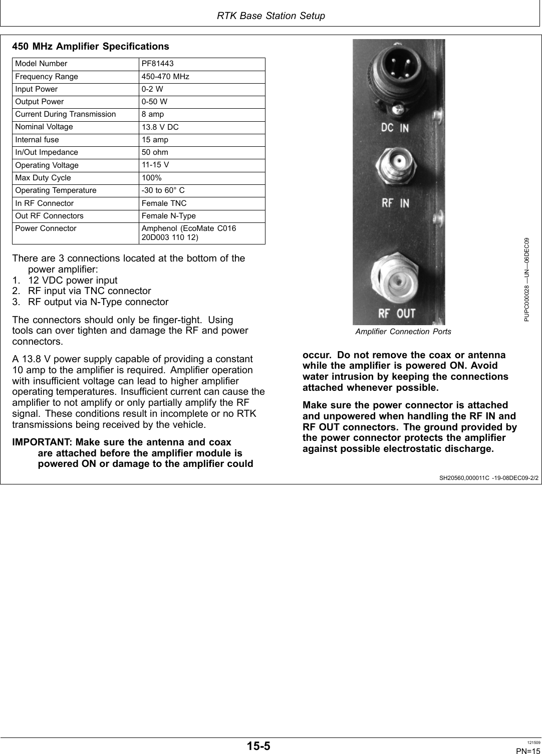
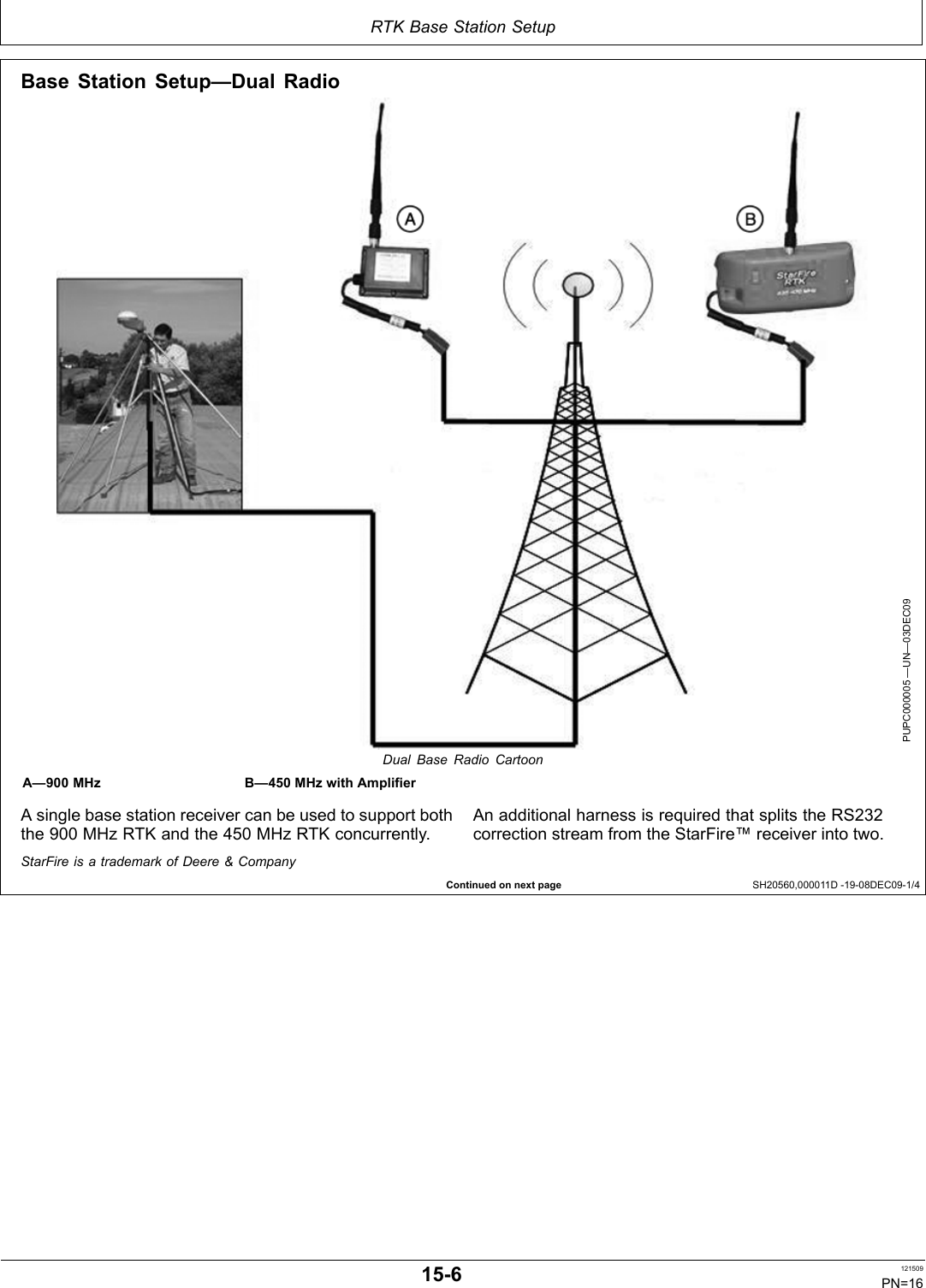
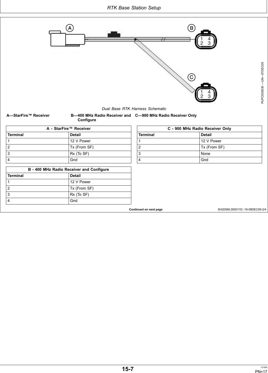
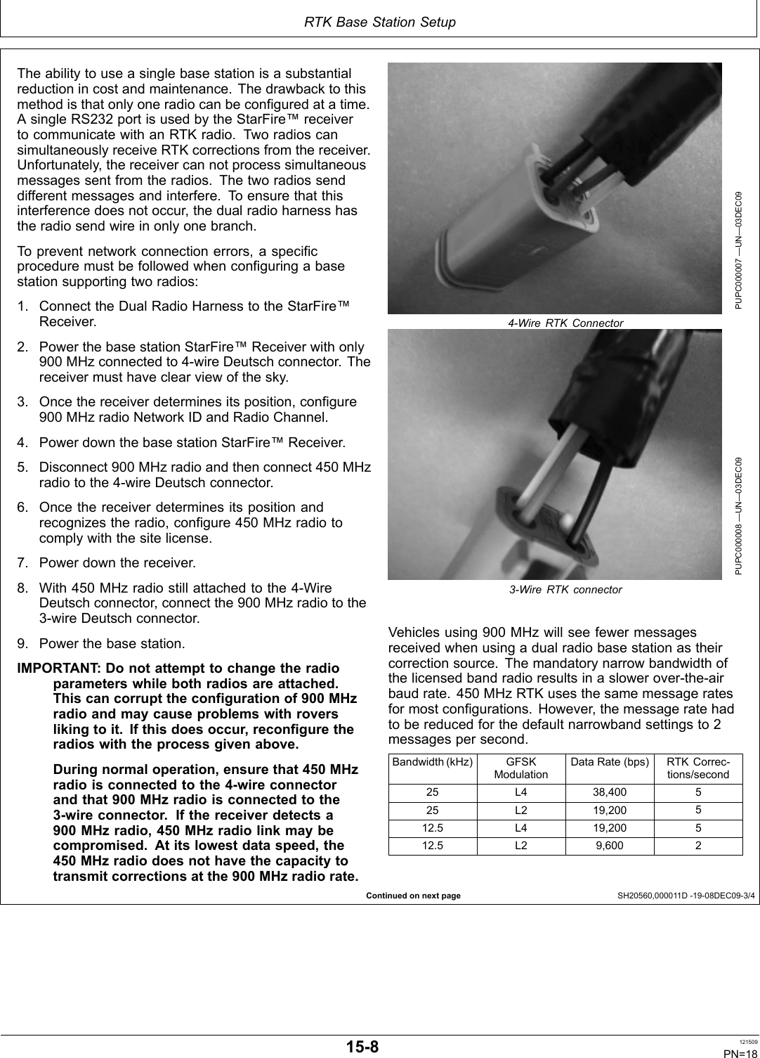
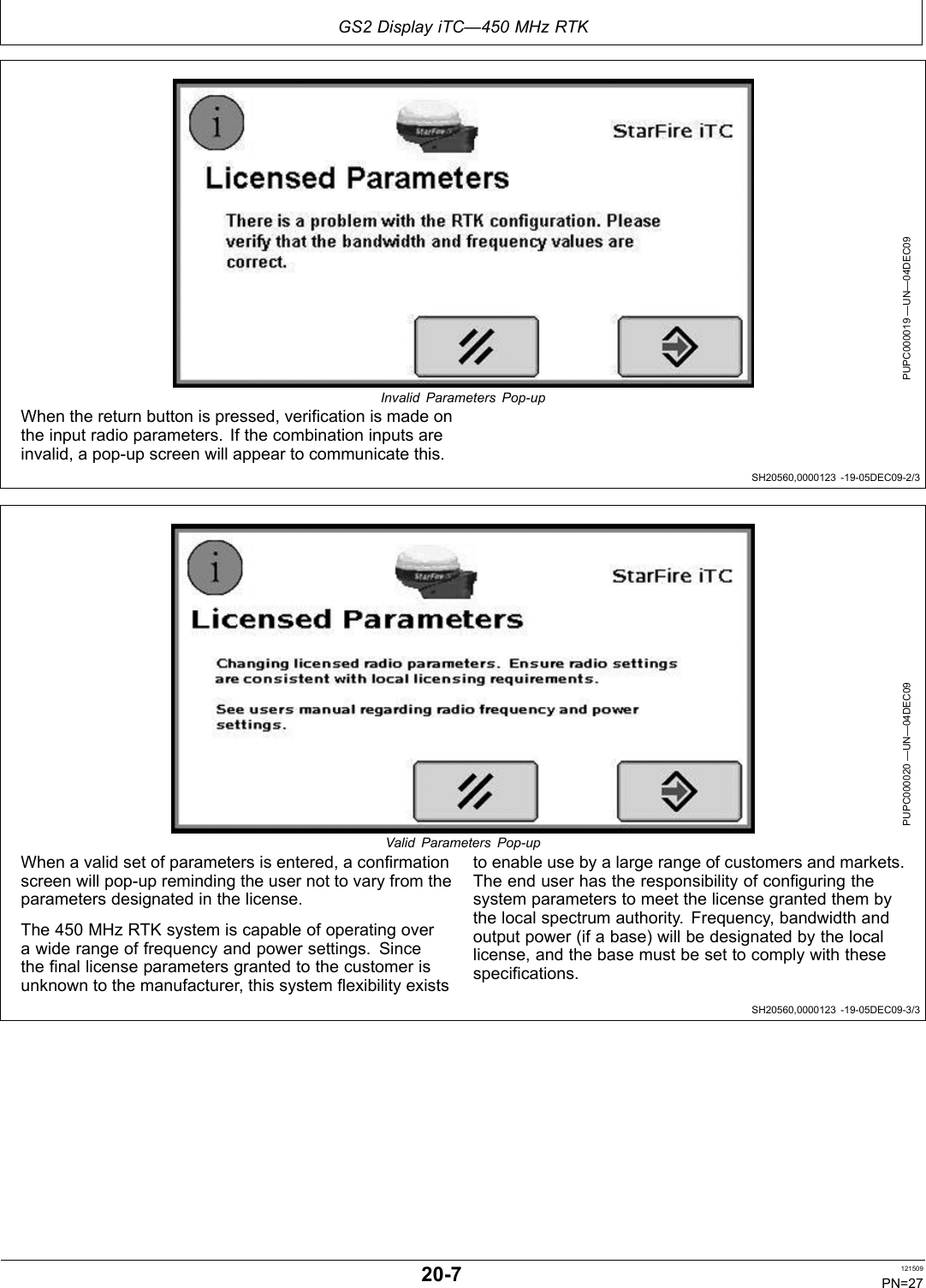
![RTK Base Station SetupSH20560,000011B 1908DEC091/1Base Station SetupThe base station is the most critical part of RTK system.During installation, care must be taken to ensure the basehas problemfree operation. There are two issues thatare responsible for most problems with a base station:Shading and Multipathing. If a base station experiencesone of these problems, it could be detrimental to your RTKoperation. These issues are shared with the 900 MHzRTK system. Mitigation techniques have already beendocumented in the standard StarFire iTC – RTK manualthat came with the iTC receiver. This manual providesdetailed recommendations to minimizing these errors.Base station operating mode can be either AbsoluteSurvey Base Mode or Quick Survey Base Mode.Once you have installed the base station receiver,installing the radio in a location to best maximize theoutput, can be a challenge. Below are several optionscurrently available through John Deere.•Leave the RTK radio in its original configurationattached directly behind the base station receiver.•Use PF80821 extension harness [92 m (300 ft.) inlength], moving the radio from the back of the basestation receiver to an elevated position, and running theharness in between.NOTE: It is important to use the PF80821 harnessand grounding wire properly according to theinstallation instructions. This harness hasbuilt in protection for both your radio andreceiver for unwanted electrical transientsdeveloped on the harness.IMPORTANT: The antenna must be installed beforethe radio module is powered ON.Avoid water intrusion by keeping theantenna attached whenever possible.Removing the antenna while transmittingmay damage the radio module.IMPORTANT: If using coaxial cable between theradio and the antenna, you need to usethe lowestloss cable available or you maysuffer RTK radio link range issues.•Attach the RTK radio in a secured location and runlowloss coaxial cable between the radio and theantenna.NOTE: When using this option, it may be necessary toinstall a highergain antenna and/or the optionalamplifier to compensate for loss.450 MHz RTK Radio SpecificationsModel Number PF81428Frequency Range 435470 MHzBandwidth Options 25 or 12.5 kHzModulation 2 and 4 level GFSKRF Baud, 25 kHz BW 19.2 kbps at L2RF Baud, 12.5 kHz BW 9.6 kbps at L21400 at 25 kHzFrequency Channels2800 at 12.5 kHzOutput Power 0.22 WSensitivity 110 dBm for 10^6 BERIn/Out Impedance 50 ohmOperating Voltage 915 VOperating Temperature 30 to 60° COut RF Connectors Female TNCControl Connector 4pin DeutschEvery 450 MHz radio comes standard with 2 dBi whipantenna that has a TNC connection.450 MHz Whip Antenna SpecificationsModel Number PF81464Gain 2 dBiFrequency Range 450470 MHzImpedance 50 ohmVSWR < 2:1RF Connector Female NTypeLength 13.2 in. (33.5 cm)Always mount the radio antenna vertically to make surethat the RTK signal is radiating outwards. If the antenna isat an angle, it may cause the data received at the vehicleto be lower than expected.NOTE: The 450 MHz RTK whip antenna, PF81464, lookssimilar to 900 MHz and 869 MHz RTK whip antennas.To differentiate, it has a white stripe near its tip.153 121509PN=13](https://usermanual.wiki/Deere-and-John-Deere-Intelligent-Solutions-Group/PCSRAMP450A/User-Guide-1303143-Page-13.png)