Deister Electronic MODEL245 Proximity Reader User Manual 460563001A
Deister Electronic GmbH Proximity Reader 460563001A
Users Manual


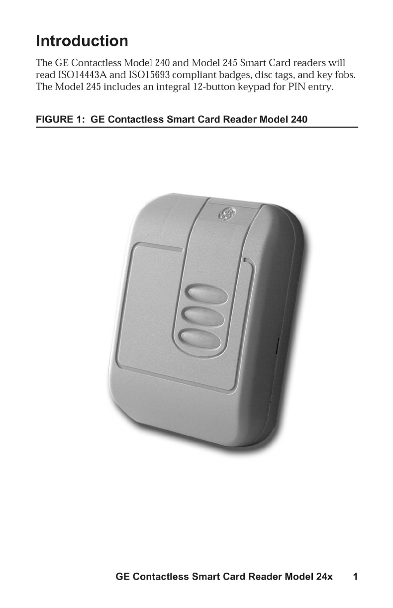
GE Contactless
Smart Card Reader
Model 240 and 245
Installation Guide
791 Park of Commerce Boulevard
Suite 100
Boca Raton, Florida 33487
(561) 998-6100
Part Number: 460563001B
January 2003

This document contains proprietary information of General Electric
Company, USA and is furnished to its customer solely to assist that
customer in the installation, testing, operation, and/or maintenance of
the equipment described. This document shall not be reproduced in
whole or in part nor shall its contents be disclosed to any third party
without the written approval of GE Industrial Systems.
GE PROVIDES THE FOLLOWING DOCUMENT AND THE
INFORMATION INCLUDED THEREIN AS IS AND WITHOUT
WARRANTY OF ANY KIND, EXPRESS OR IMPLIED, INCLUDING
BUT NOT LIMITED TO ANY IMPLIED STATUTORY WARRANTY
OF MERCHANTABILITY OR FITNESS FOR PARTICULAR
PURPOSE.
This publication may contain examples of screen captures and reports
used in daily operations. Examples include fictitious names of individuals
and companies. Any similarity to names and addresses of actual
business enterprises and persons is entirely coincidental.
Copyright 2003 GE Interlogix, CASI
All rights reserved.
Printed in the U.S.A
The Model 240 and 245 Smart Card Readers are trademarks of GE
Interlogix-CASI Division.
MIFARE®is a registered trademark of Philips Electronics, N.V.
WARNING
This is a Class A product. In a domestic environment, this product
may cause radio interference, in which case, the user may be required
to take adequate measures.
GE Contactless Smart Card Reader Model 24x i
Contents
Introduction....................................................................................................... 1
Product Overview............................................................................................. 5
Features.................................................................................................5
Access Control System Compatibility..............................................5
Installation.......................................................................................................... 7
Installation Considerations ................................................................8
Micro Compatibility............................................................................9
Reader-to-Micro Wiring Distance.....................................................9
Keypad Operation: Model 245...........................................................9
Wiring..................................................................................................10
Point-to-Point Wiring Diagrams......................................................12
Troubleshooting.............................................................................................. 19
Technical Specifications ................................................................................. 22
Regulatory Notices.......................................................................................... 23
ii GE Contactless Smart Card Reader Model 24x
Figures
Figure 1: GE Contactless Smart Card Reader Model 240 ............ 1
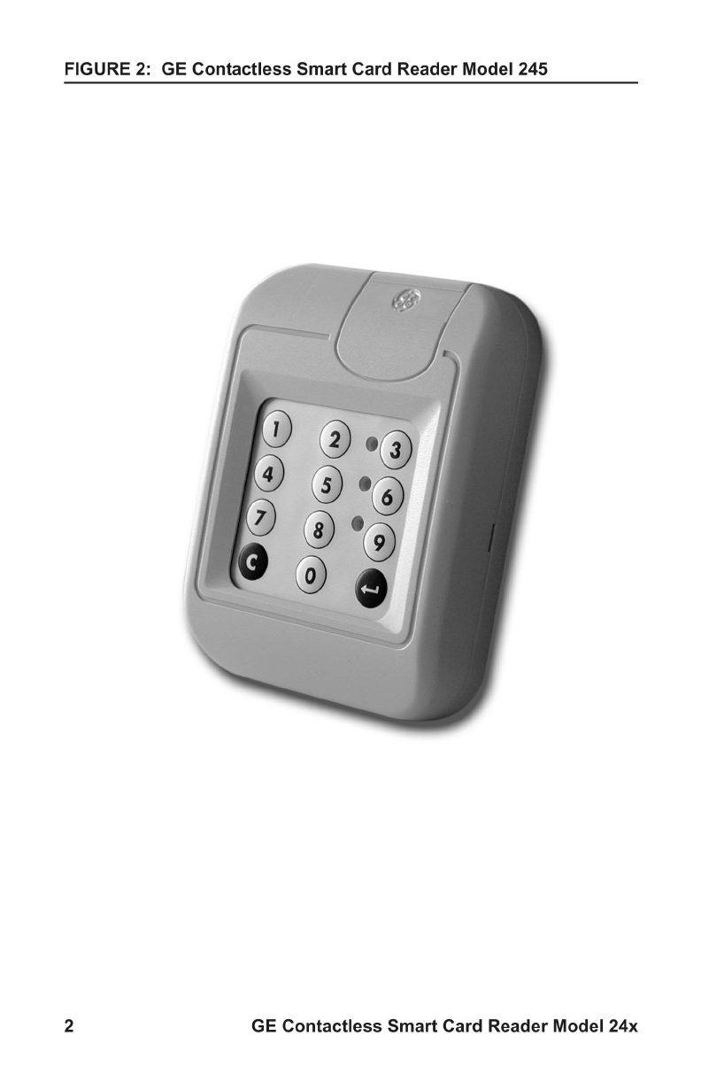
Figure 2: GE Contactless Smart Card Reader Model 245 ............ 2
Figure 3: GE Model 24x Reader Backplate
(includes tamper switch magnet) ................................... 3
Figure 4: Isolation Spacer ............................................................. 4
Figure 5: GE Model 24x Backplate and Snap-on cover ................ 7
Figure 6: Back-to-Back/Center-to-Center Installation.................... 8
Figure 7: GE Model 24x Reader Wiring Diagram to
Micro/5 8RP ................................................................. 12
Figure 8: Model 24x Smart Card Reader Wiring Diagram
to J-Box ........................................................................ 13
Figure 9: GE Model 24x Reader to 2RP...................................... 14
Figure 10: GE Model 24x Reader to 8RP...................................... 16
Figure 11: GE Model 240x Reader to Micro.................................. 18
Figure 12: Stripping of Shield Grounds ......................................... 23
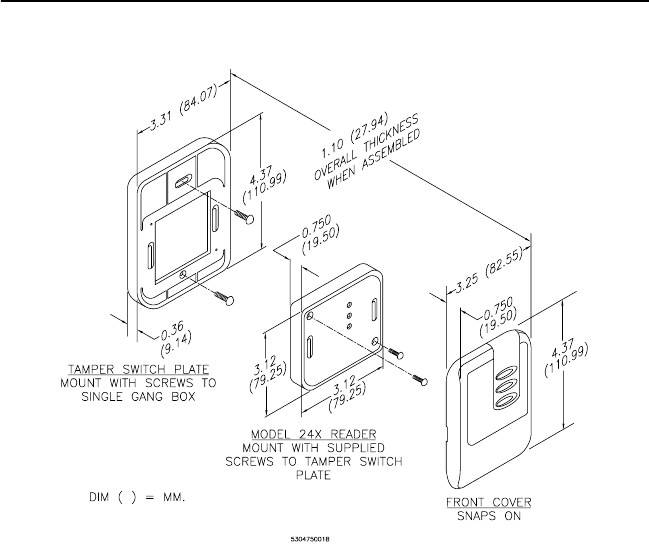
GE Contactless Smart Card Reader Model 24x 3
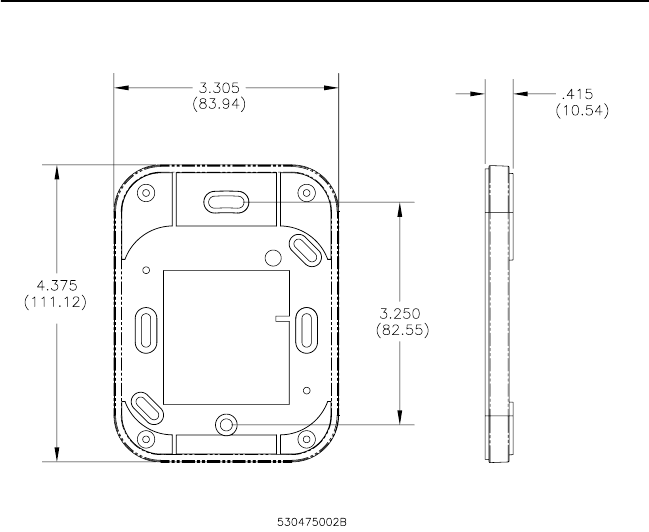
FIGURE 3: GE Model 24x Reader Backplate (includes tamper switch
magnet)
Note: Mounting holes fit standard US single-width electrical box and
standard European (EMEA) electrical box hole patterns.
An Isolation Spacer (shown in Figure 4) may be used to improve the read-
range distance when mounting to metal surfaces. Dimensions are the
same as the Reader Backplate.
4 GE Contactless Smart Card Reader Model 24x
FIGURE 4: Isolation Spacer
GE Contactless Smart Card Reader Model 24x 5
Product Overview
Features
• Universal compatibility with all ISO 15963 and ISO 14443A
credentials (badges, disc tags, and key fobs).
• Supervised four-state (open, closed, wire cut, and wire short)
monitoringfordoorcontacts,REX(requesttoexit).
• Electrical protection (reverse polarity diode protection on power
lines).
• Data lines; high-speed transient voltage suppressor diodes
• Compatible with Micro/5 2RP and 8RP Reader Processor boards,
Micro/PX-2000, and Micro/PXN-2000 controllers
• IP 65-rated sealed electronics for deployment in both interior and
exterior environments.
• Integrated reader tamper protection and supervised data
communications.
• Reads the serial BID (badge ID) number of all ISO 15693 and ISO
14443A credentials.
• 12-button tactile membrane keypad (3 x 4 matrix) for PIN (personal
identification number) entry (Model 245 only).
• RS-485 communications for reader firmware maintenance operations.
Access Control System Compatibility
The Model 24x badge reader outputs a 16-digitbadge identification(BID)
number. As a result, the Model 24x Smart Card Readers are compatible
with Picture Perfect while microcontrollers on a Secure Perfect system
must be field-configured for Model 24x compatibility.
Picture Perfect Edition Setup
Refer to Access/Badge Formats or to the Picture Perfect online help for
assistance. A 16-digit BID format must be defined within Picture Perfect.
Enter a suitable badge format description. Example: 16-digit BID
and define the format: %16S.
Secure Perfect Edition Setup
The Secure Perfect Edition access control system supports Badge IDs
(BIDs) up to a maximum of 12-digits. Since the Model 24x readers output
a 16-digit BID number, the Secure Perfect host controller/
6 GE Contactless Smart Card Reader Model 24x
microcontrollers must be specially configured to receive the incoming 16-
digit BID numbers, and convert them into the proper 12-digit BID format.
To make a Secure Perfect 4.0 or higher system compatible with the
complete line of GE Contactless Smart Card Reader, do the following:
• Install Secure Perfect Edition, 4.0 or higher
•LoadtheSecure Perfect Update CD in the server CD drive
• Locate the Badge Formats folder
• In the Badge Formats folder, locate the 15693.REG file
• Double-click the 15693.REG to configure the Secure Perfect Edition
system
This file configures the Secure Perfect Edition’s system to communicate
with the GE Contactless Smart Card Readers.
GE Contactless Smart Card Reader Model 24x 7
Installation
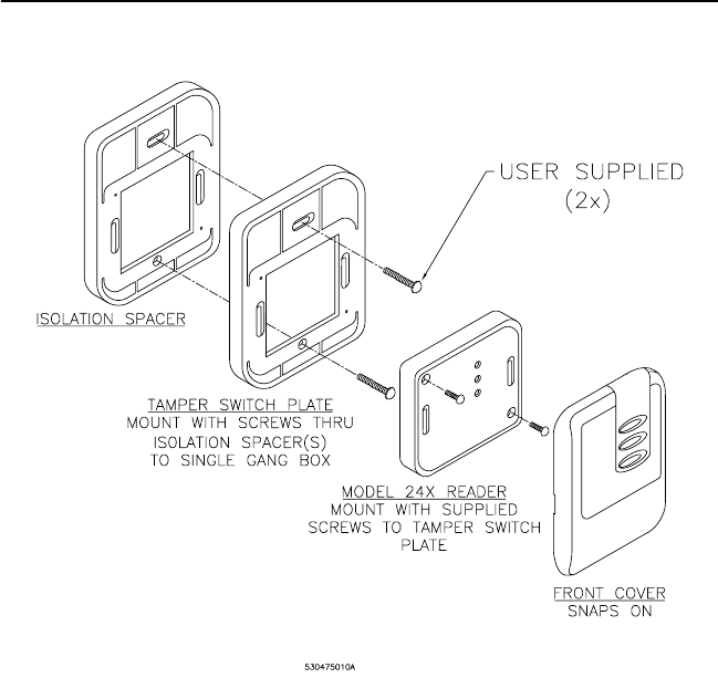
FIGURE 5: GE Model 24x Backplate and Snap-on cover
The front cover snaps into place. To remove the cover, use a small flat-
blade screwdriver to pry the cover from the backplate, using either of the
two provided locations on the vertical sides of the reader.
Installation of the Model 245 is similar to that of the Model 240.
8 GE Contactless Smart Card Reader Model 24x
Installation Considerations
1. Installation of the GE Model 24x Reader on metal.
Read-range reduction can be improved by adding Isolation Spacers
(approximately 25% per plate).
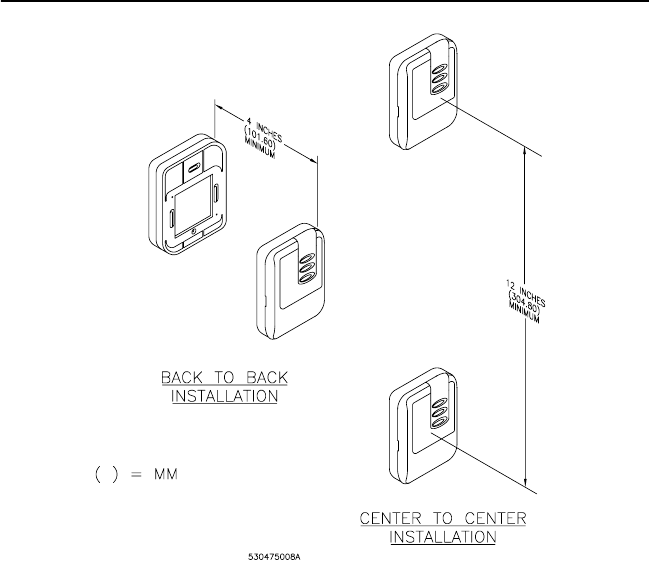
2. Installation of two Model 24x Smart Card Readers side-by-side.
Read range is not affected if the center-to-center distance between
two readers is equal to or greater than four inches (101.60 mm). If the
distancebetweenthetworeadersislessthanfourinches(101.60
mm), field interference between the two readers may result in a
double-badge read field. In that case, add a metal back-to-back
mounting plate. This can be improved by adding Isolation Spacers.
Note: Two readers can simultaneously read the same badge or tag if the
distance between the two readers is less than 12 inches (304.8 mm), center-
to-center.
FIGURE 6: Back-to-Back/Center-to-Center Installation
3. Installation of two GE Model 24x Readers back-to-back.

GE Contactless Smart Card Reader Model 24x 9
When installing two readers back-to-back on a wall that will separate
the two readers by four inches (101.60 mm) or less, a metal plate (for
example: Reader isolation plate, metal wall) must be placed between
the readers. To obtain the maximum read range, mount each GE
Model 24x Smart Card Reader onto one or more Isolation Spacers.
Note: Two readers can simultaneously read the same badge or tag if the
distance between the two readers is less than four inches (101.60 mm),
back-to-back.
Micro Compatibility
• Micro/5 Controller with either 2RP or 8RP Reader Boards: refer to
the Micro/5 Installation Guide.
IMPORTANT: DO NOT use the GE Model 24x Readers with the Micro/5 2SRP.
• Micro/PX-2000 and Micro/PXN-2000 controllers: refer to theMicro/
PX-2000 and Micro/PXN-2000 Installation Guide.
• Micro/Reader-Junction Box: refer to the point-to-point wiring
diagrams in this manual.
Reader-to-Micro Wiring Distance
Table 1: Current and Cable Distance
Keypad Operation: Model 245
The reader sends each key press to the microcontroller and the yellow
LED will blink. The reader beeper sounds with each key press.
Supply Voltage Cable Distance
Model 240 and 245 12 VDC 13.6 VDC
Current 18 AWG 22 AWG 18 AWG 22 AWG
105 mA @12 VDC 2,041 ft.
(622 m)
856 ft.
(262 m)
3,123 ft.
(952 m)
1,309 ft.
(399 m)

10 GE Contactless Smart Card Reader Model 24x
Wiring
Table 2: Reader 12-Position Field Wiring Connector
Pin Definition
1 Micro control, reader beeper (option)
2 Ground
3 8VDCto30VDC
4 Door contact
5 Reader Data 1
6 Exit request (REX)
7GreenLED
8 Micro control, red LED (option)
9 RS-485-B, reader firmware maintenance
10 RS-485-A, reader firmware maintenance
11 Reserved for future use
12 Reserved for future use
GE Contactless Smart Card Reader Model 24x 11
Installation Notes (unless otherwise specified). All numbered items below are
referenced on the appropriate wiring diagrams throughout this manual.
1. Fuse, power supply, door strike, protection device, and relay are provided by
the installer.
2. The included 470 Ω ½-watt pull-up resistor must be installed at the
microcontroller’s terminal block. The Micro PX-2000 and 8RP boards do not
require this resistor.
3. Shielded cable is recommended in electrically noisy environments.
4. If using shielded cable: At the reader end: connect all shields together and
insulate them. At the Micro end: connect the shield to the Micro cabinet as
indicatedin the appropriate Micro Installation Manual.
5. Make sure the distance of the wiring from the power supply to the reader is
less than 50 feet (15.24 mm). If using a local power supply, do not connect the
power (8-30 VDC) line from the microcontroller to the reader. The ground
line of the power supply must be connected to the micro (pin 2 on the reader
connector).
6. J3 is typically not used in this installation. For additional information, see the
appropriate Micro/Reader Junction Box Installation Instructions.
7. Blocking diodes may be 1N4148 or similar (installer supplied) and located in
asecurearea.
8. Protection diodes may be 1N4002, 1N4003, or 1N4004 (installer supplied) for
the door strike assembly.
9. Install two 1k Ω ¼-watt high-quality resistors at Door DI and Exit DI, as
shown.
10. Connect a protection device across a door strike.
AC Door Strikes: Connect a MOV (metal oxide varistor) across the door
strike.
DC Door Strikes: Connect a diode across the door strike (cathode to positive
side of door strike)
11. Relay Coil Current Restriction (Micro/5 2RP with external relay).
The relay coil current must be limited to 40 mA to prevent damage to the
board. Verify that the relay coil requires less than 40 mA.
12 VDC relay: coil resistance must be greater than 300 Ω.
The Micro/5 2RP with internal or AUX DO relay current through the relay
contacts must be limited to less than 2A to prevent damage to the 2RP.
Current limiting may be achieved by using either a current-limiting power
supplyorbywiringinanexternalfuse.
12. Connect protection diode across relay coil. Connect a diode across the relay
coil (cathode to positive side of relay coil).
General note: Pair wires as shown in all wiring diagrams.
12 GE Contactless Smart Card Reader Model 24x
Point-to-Point Wiring Diagrams
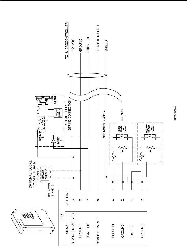
FIGURE 7: GE Model 24x Reader Wiring Diagram to Micro/5 8RP
GE Contactless Smart Card Reader Model 24x 13
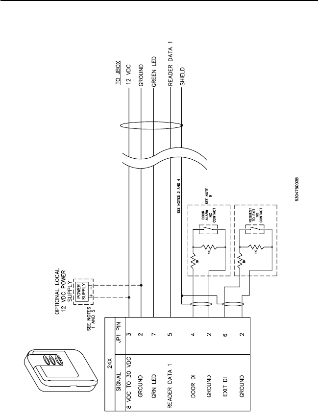
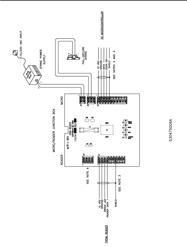
FIGURE 8: Model 24x Smart Card Reader Wiring Diagram to J-Box


GE Contactless Smart Card Reader Model 24x 15
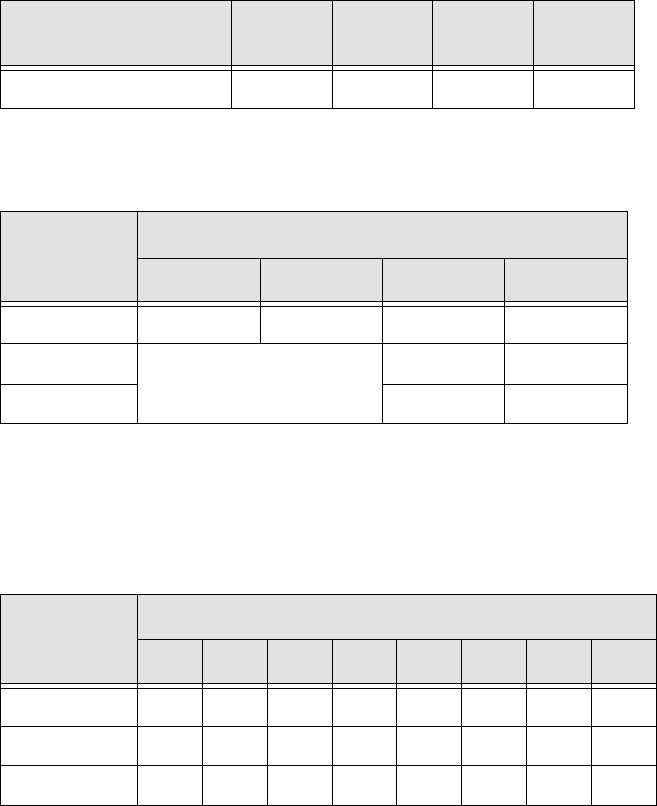
Table 4: 2RP Reader Board Address Settings
Note: Switches SW2-5, 6, 7, and 8 are not used.
Jumper W1 RN2 and RN5 (labeling)
Set to 12 V Use 2k Ω(202) resistor packs.
Table 3: 2RP Reader Switch Settings
Reader Technology
and Format SW-1 SW-2 SW-3 SW-4
Supervised F/2F ON OFF ON OFF
Reader
Board
SW 1 SW 2
56781234
1ON OFF OFF OFF ON OFF OFF OFF
2OFF ON OFF OFF OFF ON OFF OFF
3OFF OFF ON OFF OFF OFF ON OFF
4OFF OFF OFF ON OFF OFF OFF ON
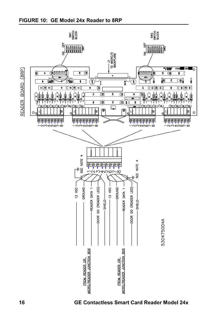
GE Contactless Smart Card Reader Model 24x 17
Note: the 8RP board appears to the Micro as four 2RP boards.
Table 5: 8RP Reader Technology and Format
Reader Technology and
Format SW1-1 SW1-2 SW1-3 SW1-4
Supervised F/2F ON OFF ON OFF
Table 6: 8RP Board Address Settings
Board Type
SW 1
5 6 7 8
Standard ON ON ON OFF
Board 1a
a. Readers 1 - 8
Does not apply. OFF ON
Board 2b
b. Readers 9 - 16
OFF ON
Board Type
SW 2
12345678
Standard OFF OFF ON ON ON OFF ON OFF
Board 1a
a. Readers 1 - 8.
ON OFF ON OFF ON OFF ON OFF
Board 2b
b. Readers 9 -16.
ON ON OFF OFF OFF ON OFF ON

GE Contactless Smart Card Reader Model 24x 19
Troubleshooting
If the operation of a component is in doubt, substitute a known-good
component and retry the system. Always verify wiring against the
provided wiring before powering up the system.
Table 7: Error Conditions and Possible Solutions
Condition Possible Solutions
None of the
LEDs are on.
Present a known-good ISO 15963 or ISO 14443A
type card to the reader while listening for the
beeper. If the beeper sounds, the reader is faulty
and should be replaced. If the beeper does not
sound, check the following:
•Power connections to the reader
•Reader supply voltage at connector JP1 pin 3
and that the ground connection JP1 pin 2 is
secure
The green LED is
always on. The
green LED indi-
cates that the
door strike is
open. It is con-
trolled by the
input on connec-
tor JP1 pin 7.
Disconnect the wire on JP1 pin 7. If the green LED
stays on, the reader is faulty and should be
replaced. If the green LED goes off, then the prob-
lem is most likely not in the reader.
Reconnect the wire on JP1 pin 7 and measure the
voltage at JP1 pin 7. A low voltage (0 to 2 VDC)
lights the green LED. If the voltage is low, there
are two possibilities:
•A short to ground in the wiring between the
reader and microcontroller, or
•The host system may be energizing the door
strike
The door does
not open and the
green LED does
not light when an
ISO 15963 or
ISO 14443A card
is presented.
Verify that the door strike and the green LED are
wired correctly.
Verify that the access card has been entered and
that the reader has been properly configured in
the host system.

20 GE Contactless Smart Card Reader Model 24x
The green LED
does not light,
but the door
strike unlocks the
door when a valid
ISO 15693 card
is presented.
Verify that the door strike is wired correctly. Refer
to the appropriate wiring diagram.
Disconnect the wire from JP1 pin 7 (green LED)
and connect JP1 pin 7 to JP1 pin 2 (ground). If the
green LED is now on, the reader is good and the
connection to the reader is defective. If the green
LED does not light, replace the reader.
Green LED
lights, but the
door does not
open.
Verify correct door strike wiring and operation. The
reader is functioning. If not, check that the block-
ing diode is functioning. If it is not, replace it.
Reader sounds a
short triple beep
every 30 seconds
and the red LED
flashes slowly
(every 2 sec-
onds).
The reader has lost communication with the micro-
controller.
Check the reader-to-microcontroller wiring, in par-
ticular, the terminations for Reader Data 1. Refer
to the appropriate wiring diagram. Verify that the
2RP AUX DO is jumpered to the reader data 1 on
the microcontroller. Jumper between 2RP JP2 and
JP4, pins 3 and 7.
Verify that the correct pull-up resistor is installed
on the microcontroller (470 Ω½-watt, 2RP JP2
and JP4, pins 1 and 3).
Verify that the microcontroller has the correct firm-
ware. Refer to the manual that came with your
microcontroller for instructions.
Try the reader on a different reader input port at
the microcontroller. If this corrects the problem,
the operational status of the original port is sus-
pect.
Replace the reader with one you know is working
correctly. If this corrects the problem, then the
reader is probably faulty and should be replaced.
If none of the above steps have identified the
problem, there may be a significant noise source
present in the installation which is interfering with
the reader-to-microcontroller communications. If
this is the case, use shielded wire for reader-to-
microcontroller connections.
Condition Possible Solutions

GE Contactless Smart Card Reader Model 24x 21
The reader
sounds a short
triple beep every
30 seconds and
the red LED
flashes quickly
(every 400 ms).
Indicates a tamper violation. Ensure the reader is
properly attached to its backplate. The red LED
will continue to blink for 30 seconds. The reader is
ready for use when the yellow LED is steadily on.
The reader
sounds a short
triple beep every
5 seconds and
the red LED
also flashes
every 5 seconds.
Check that the 4-state supervised switches are
connected with two 1K Ωresistors to the door con-
tact and the exit request inputs or, if the inputs are
not used, that a 1K Ωresistor is installed at the
reader connector.
A 470 Ω½-watt pull-up resistor is required
between 12 VDC and Reader Data 1 on the Micro/
52RP(only).
Condition Possible Solutions
22 GE Contactless Smart Card Reader Model 24x
Technical Specifications
• Cable: Belden (shielded) 8777, 9873, 9773
• Certifications: FCC Part 15; CE Mark, and UL 294 (pending)
• Color: Gray
• Dimensions with backplate (height/width/depth): 4.37” x 3.31” x
1.10” (110.99 x 84.07 x 27.94 mm)
• Environments: interior or exterior
• Humidity Range: 5 to 95%, non-condensing
• Index of Protection: IP 65 (IEC 529)
• 12-button (3 x 4 matrix) tactile membrane keypad (GE Model 245
only)
• Microcontroller Communications: F/2F supervised door input, REX,
and reader communication/power monitoring
• Minimum Wiring: 4 conductors
• Operating Temperature/Range: -13 to 140oF(-25to60
oC)
• Power supply: 8 - 30 VDC (see requirements below)
• Weight:5.6oz(158.75g)
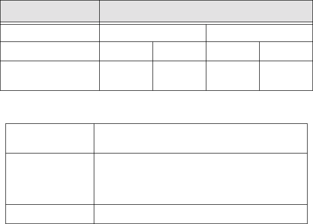
Table 8: Currents, Ranges, and Distances
Table 9: Functional Specifications
Supply Voltage Cable Distance
Model 240 and 245 12 VDC 13.6 VDC
Current 18 AWG 22 AWG 18 AWG 22 AWG
105 mA @12 VDC 2,041 ft.
(622 m)
856 ft.
(262 m)
3,123 ft.
(952 m)
1,309 ft.
(399 m)
International
Standards
ISO 15693 and ISO 14443A
Microcontroller
compatibility
• Micro/5-PX and Micro/5-PXN with 2RP and 8RP
processor boards (incompatible with M/5 and
2SRP board configurations)
• Micro/PX-2000 and Micro/PXN-2000
Status Indicators Red, Yellow, and Green LEDs and Beeper
GE Contactless Smart Card Reader Model 24x 23
Regulatory Notices
FCC
Changes or modifications not expressly approved by GE-Interlogix for
compliance could void the user’s authority to operate the equipment.
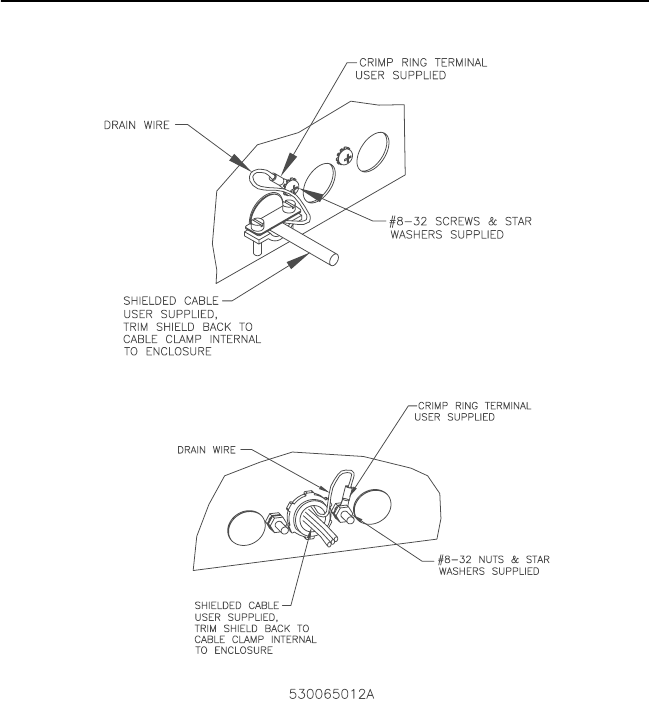
FCC and CE Compliance.
Shield grounds must be stripped back through the knockout hole (strain
relief) and grounded to the external ground stud provided on the
microcontroller.
FIGURE 12: Stripping of Shield Grounds

24 GE Contactless Smart Card Reader Model 24x
CE Manufacturers Declaration
of Conformity
Manufacturer’s
Name: GE Interlogix, CASI
Manufacturer’s
Address:
791 Park of Commerce Boulevard, Suite 100
Boca Raton, FL USA 33487
EU Representative: Interlogix Europe & Africa
Excelsiorlaan 28
B- 1930 Zaventum
Belgium
Product
Identification:
Product: GE Interlogix, CASI Smart Card Reader
Model Number: 240, 245
Brand: CASI
Means of Conformity: • Hereby, GE Interlogix, CASI, declares that this
equipment is in compliance with the essential
requirements and other relevant provisions of
Directive 1999/5/EC.
• Hierbij verklaart GE Interlogix, CASI dat het
apparoat in overeenstemming is met de
essentiële eisen en de andere relevante
bepalingen van richtlijn 1999/5/EG.
• Par la présente GE Interlogix, CASI déclare
que l'appareil est conforme aux exigences
essentielles et aux autres dispositions
pertinentes de la directive 1999/5/CE.
• Hiermit erklärt GE Interlogix, CASI, dass sich
dieseAusrüstunginÜbereinstimmungmitden
grundlegenden Anforderungen und den
anderen relevanten Vorschriften der Richtlinie
1999/5/EG befindet". (BMWi)
Notices: Approved for use in the following countries:
A
B
DK
FIN
IS
IRL
GR
D
I
NL
F
CZ
H
LU
N
PL
P
E
S
CH
GB
GE Contactless Smart Card Reader Model 24x 25
26 GE Contactless Smart Card Reader Model 24x
GE Contactless Smart Card Reader Model 24x 27
28 GE Contactless Smart Card Reader Model 24x