Deister Electronic MODEL260 Proximity Reader User Manual 460565001A
Deister Electronic GmbH Proximity Reader 460565001A
Users Manual

GE Contactless
Medium Read-Range
Reader
Model 260
Installation Guide
791 Park of Commerce Boulevard
Suite 100
Boca Raton, Florida 33487
(561) 998-6100
Part Number: 460565001A
February 2003

This document contains proprietary information of General Electric
Company, USA and is furnished to its customer solely to assist that
customer in the installation, testing, operation, and/or maintenance of
the equipment described. This document shall not be reproduced in
whole or in part nor shall its contents be disclosed to any third party
without the written approval of GE Industrial Systems.
GE PROVIDES THE FOLLOWING DOCUMENT AND THE
INFORMATION INCLUDED TH EREIN AS IS AND WITHOUT
WARRANTY OF ANY KIND, EXPRESS OR IMPLIED, INCLUDING
BUT NOT LIMITED TO ANY IMPLIED STATUTORY WARRANTY
OF MERCHANTABILITY OR FITNESS FOR PARTICULAR
PURPOSE.
This publication may contain examples of screen captures and reports
used in daily operations. Examples include fictitious names of individuals
and companies. Any similarity to names and addresses of actual
business enterprises and persons is entirely coincidental.
Copyright 2003 GE Interlogix, CASI
All rights reserved.
Printed in the U.S.A
MIFARE® is a registered trademark of Philips Electronics, N.V.
WARNING
This is a Class A product. In a domestic environment, this product
may cause radio interference, in which case, the user may be required
to take adequate measures.
Model 260 Smart Card Reader i
Contents
Introduction....................................................................................................... 1
Product Overview............................................................................................. 3
Features.................................................................................................3
Access Control System Compatibility..............................................3
Mounting Considerations................................................................................ 5
Environmental Interference ...............................................................5
Installation on Metal Surface.............................................................7
Installation........................................................................................................ 11
Installation: Model 260 on Metal.....................................................12
Micro Selection...................................................................................13
Reader-to-Micro Wiring Distance...................................................13
Wiring..................................................................................................14
Point-to-Point Wiring Diagrams......................................................16
Troubleshooting.............................................................................................. 23
Technical Specifications ................................................................................. 26
Regulatory Notices.......................................................................................... 28
ii GE Contactless Medium Read-Range Reader Model 260
Figures
Figure 1: GE Contactless Medium Read-Range Reader
(Model 260).................................................................... 1
Figure 2: GE Model 260 Reader Backplate
(includes tamper switch) ................................................ 2
Figure 3: GE Model 260 Reader Environmental Considerations .. 5
Figure 4: Pole-Mounted Readers .................................................. 7
Figure 5: Parking Entrance/Exit Application A............................... 8
Figure 6: Parking Entrance/Exit Application B............................... 9
Figure 7: Parking Entrance Exit and Metal Sign Applications ..... 10
Figure 8: Model 260 Reader Backplate and Cover ..................... 11
Figure 9: GE Model 260 Reader Wiring Diagram to
Micro/5 8RP 16
Figure 10: GE Model 260 Reader Wiring Diagram to J-Box ......... 17
Figure 11: GE Model 260 Reader to 2RP ..................................... 18
Figure 12: GE Model 260 to 8RP .................................................. 20
Figure 13: GE Model 260 Reader to Micro/Reader
Junction Box and Microcontroller 22
Figure 14: Stripping of Shield Grounds ......................................... 28
GE Contactless Medium Read-Range Reader Model 260 1
Introduction
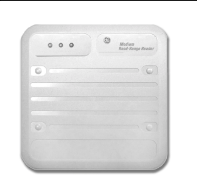
The GE Contactless Medium Read-Range Card (Model 260) is the latest evolution
in contactless reader 13.56 MHz technology, and features universal compatibility
with all ISO 15693 and ISO 14443A badge credentials. The GE Model 260 reader
combines simple, cost-effective installation with the end-user convenience of
extended read range. The reader housing is a durable gray polycarbonate making
the reader equally well-suited for interior and exterior security locations. The
reader is easy to install on all types of conventional and metal wall surfaces,
stanchions, and pedestal-mount configurations.
FIGURE 1: GE Contactless Medium Read-Range Reader (Model 260)
2 GE Contactless Medium Read-Range Reader Model 260
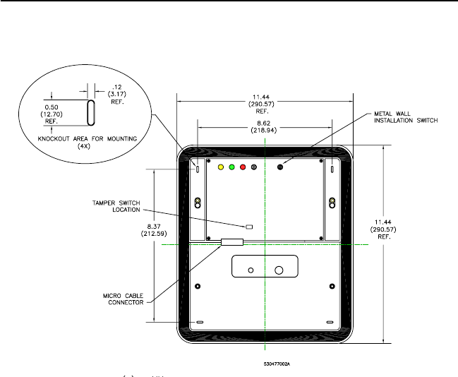
FIGURE 2: GE Model 260 Reader Backplate (includes tamper
switch)
GE Contactless Medium Read-Range Reader Model 260 3
Product Overview
Features
• Exceptional read range of up to 14 inches (355.6 mm) for ISO 15693-
compliant credentials. (Read range will vary with credential type and
quality, as well as installation environment).
• Universal compatibility with all ISO 15693 and ISO 14443A
credentials (badges, disc tags, and key fobs).
• Supervised four-state (open, closed, wire cut, and wire short)
monitoring for door contacts and REX (request to exit) switches, and
wiring.
• Electrical protection (reverse polarity diode protection on power
lines).
• Data lines; high-speed transient voltage suppressor diodes
• Compatible with Micro/5 2RP and 8RP Reader Processor boards,
Micro/PX-2000, and Micro/PXN-2000 controllers
• IP 65-rated sealed for deployment in both interior and exterior
environments.
• Integrated reader tamper protection and microcontroller supervised
data communications.
Access Control System Compatibility
The Model 260 badge reader outputs a 16-digit badge identification (BID)
number. As a result, the Model 260 reader is compatible with Picture
Perfect while microcontrollers on a Secure Perfect system must be field-
configured for Model 260 compatibility.
Picture Perfect Edition Setup
Refer to Access/Badge Formats or to the Picture Perfect online help for
assistance. A 16-digit BID format must be defined within Picture Perfect.
Enter a suitable badge format description. Example: 16-digit BID
and define the format: %16S.
Secure Perfect Edition Setup
The Secure Perfect Edition access control system supports Badge IDs
(BIDs) up to a maximum of 12-digits. Since a Model 260 reader will
output a 16-digit BID number, the Secure Perfect microcontrollers must
be specifically configured to receive the incoming 16-digit BID number,
and convert it into the Secure Perfect-compatible 12-digit BID format.
4 GE Contactless Medium Read-Range Reader Model 260
To make a Secure Perfect 4.0 or higher system compatible with the GE
Contactless Medium Read-Range Readers, do the following:
• Install Secure Perfect Edition, 4.0 or higher
•Load the Secure Perfect Update CD in the server CD drive
• Locate the Badge Formats folder
• In the Badge Formats folder, locate the 15693.REG file
• Double-click the 15693.REG to configure the Secure Perfect Edition
system and microcontrollers for operation with GE Contactless
Medium Read-Range Readers
Note: For earlier versions of Secure Perfect Editions, please contact CASI
Sales Engineering for the 15693.REG file.
This file configures the Secure Perfect Edition’s system to communicate
with the GE Contactless readers. To restore Secure Perfect Edition’s
system back to factory settings, install the BADGE FORMATS.REG file.
GE Contactless Medium Read-Range Reader Model 260 5
Mounting Considerations
FOR PROTECTION AGAINST ENVIRONMENTAL INTERFERENCE
Model 260 readers require care and consideration in the manner in which
they are mounted. This includes consideration of the other equipment
and structural elements that are mounted near the reader, whether visible
or hidden. The following covers the major factors to consider.
Environmental Interference
There are three types of environmental interference:
1. Electrical Noise (field wiring related)
2. Field Blocking (conductive material in read field)
3. Overlapping Fields (side-to-side & back-to-back installation)
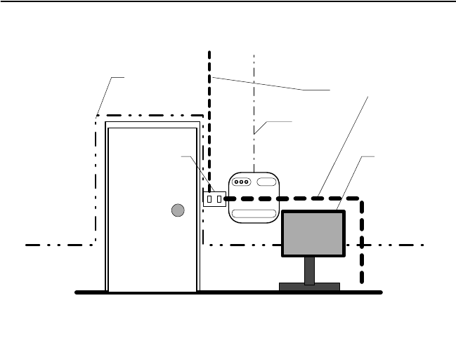
FIGURE 3: GE Model 260 Reader Environmental Considerations
Model 260
Sample Entranceway
Door
Light Switch
Power Wiring
Data
Network
Wiring
Security
Wiring Signs &
Other
Metal
Objects
6 GE Contactless Medium Read-Range Reader Model 260
The reader may encounter a wide range of interference as shown in
Figure 3, “GE Model 260 Reader Environmental Considerations,” on
page 5. Common causes include:
Power Wiring
Power wiring carries electrical noise that can interfere with the operation
of the reader. This is more common with traditional 125 KHz proximity
readers. However, this is a potential issue with the GE Model 260 reader,
particularly if data noise is introduced by coupling from the reader’s
power wiring. Any power wire may inductively or capacitively couple
noise into the reader data line.
Data Network Wiring
Data network wiring can generate noise, which may possibly be in the
operating frequency range of the reader. This noise can interfere with
reader-to-credential communication and reduce read range.
Security Wiring
While not normally a source of noise itself (although it can cause
problems if bundled in a loop directly behind the reader), security wiring
can inductively or capacitively couple to data or power wiring, and
transfer noise to the reader.
Signs and Other Metal Objects
Signs and other metal objects within the read field of the reader can
absorb or block reader-to-credential communication and reduce range.
Use shielded cable for reader communication. Reader installation
considerations should avoid read field blocking and overlapping
conditions.
GE Contactless Medium Read-Range Reader Model 260 7
Installation on Metal Surface
Mounting the GE Reader directly on a metal (or other electrical
conducting surface) will reduce read range to approximately 9.45 inches
(240 mm). For maximum read-range, ensure the metal wall installation
switch is set to the “< 0.75 inch” position.
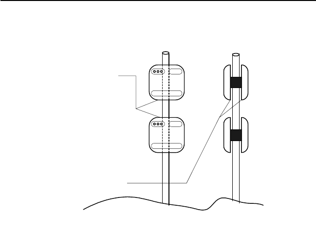
Another potential source of interference is mounting two or more readers
in close proximity as shown in Figure 4.
FIGURE 4: Pole-Mounted Readers
The following problems may occur when mounting multiple GE Model
260 readers in close proximity:
• The signal energy from one reader may interfere with the read range
of the other.
• Overlapping read fields can cause a single credential to be read
simultaneously by two or more readers.
Front
view Side
view
Vertical separation
distance
Back-to-back
distance
8 GE Contactless Medium Read-Range Reader Model 260
To ensure proper operation and optimal read range, take the following
precautions:
1. Mount all readers before tuning any of the readers.
2. Ensure that the back-to-back distance is at least 3.28 feet (one meter).
Note: If a metal plate is installed between the two readers, the
back-to-back distance restriction may be ignored. However, read
range will be reduced to approximately 9.45 inches (240 mm).
Note 2: Reduced credential read range and the simultaneous read of
a credential by both readers may result if the readers are installed
less than 19.68 inches (500 mm) apart.
3. Ensure that the vertical separation distance is at least 19.68 inches
(500 mm). A more narrow vertical separation gap may be used if the
simultaneous read of a credential by two or more readers is
acceptable.
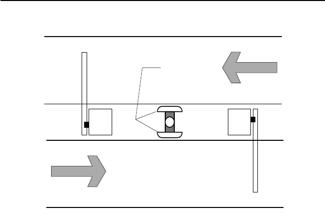
FIGURE 5: Parking Entrance/Exit Application A
A common use for the GE Model 260 is parking lot applications.
However, the parking lot application presents opportunities for all of the
interference types as described earlier.
Gate
Ctrl
Gate
Ctrl
IN
OUT
Back-To-back
distance
GE Contactless Medium Read-Range Reader Model 260 9
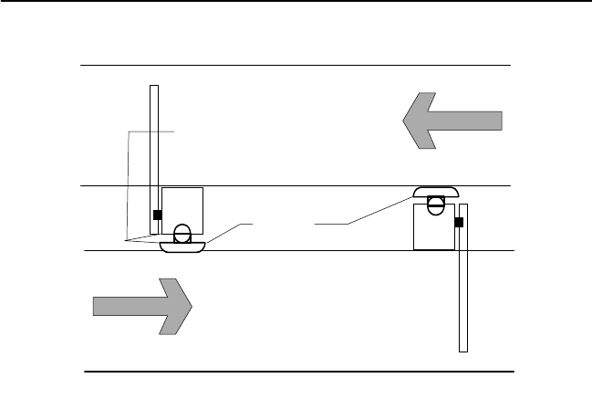
FIGURE 6: Parking Entrance/Exit Application B
In Application A, the back-to-back and (if used) vertical gap guidelines
above must be observed. Remember to mount all readers (and all other
structures) before tuning the reader.
In Application B, successful installation requires close attention to
electrical noise from the gate control mechanism (and its associated
wiring) that may cause reader-to-reader signal interference.
Gate
Ctrl Gate
Ctrl
IN
OUT
Readers
Reader-Control
Gap
10 GE Contactless Medium Read-Range Reader Model 260
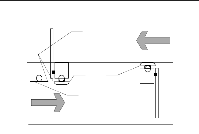
FIGURE 7: Parking Entrance Exit and Metal Sign Applications
Signs and other metal objects, including hidden wiring may interfere
with the reader’s read field.
Metal signs are common items in both indoor and outdoor installations.
The signs may be free standing (see Figure 3, “GE Model 260 Reader
Environmental Considerations,” on page 5) or fixed in position (see
Figure 7, “Parking Entrance Exit and Metal Sign Applications,” on
page 10.)
To ensure optimal read-range performance, ensure all metal signs and
other conductive objects are placed at a distance that is at least:
• 19.68 inches (500 mm) from the front of the reader.
• 5.91 inches (150 mm) from the back of the reader.
• 3.94 inches (100 mm) from the side of the reader.
Gate
Ctrl Gate
Ctrl
IN
OUT
Readers
Metal sign
Reader/sign
distance
GE Contactless Medium Read-Range Reader Model 260 11
Installation
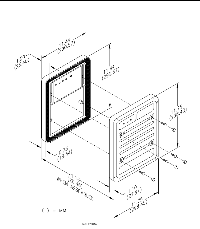
FIGURE 8: Model 260 Reader Backplate and Cover
The cover is secured with four supplied screws (screw hole plugs
included).
12 GE Contactless Medium Read-Range Reader Model 260
Installation: Model 260 on Metal
The GE Model 260 reader can be field-tuned to accommodate installation
on or near metal surfaces. To accomplish this, perform the following
steps:
1. Remove the front cover.
2. Mount reader back-plate assembly.
3. Terminate the communications cable at the microcontroller using the
wiring diagram in Figure 9, “GE Model 260 Reader Wiring Diagram
to Micro/5 8RP,” on page 16 or Figure 11, “GE Model 260 Reader to
2RP,” on page 18.
4. Terminate the communications cable at the reader using the wiring
diagrams in Figure 10, Figure 11, Figure 12, or Figure 13.
5. Wall-type selection switch. Set the two-position slide switch to match
the wall surface.
6. Connect the communications cable to power up the reader.
IMPORTANT: Within three seconds, you must press the Tune
button or the reader will go into tamper operation (red LED flashes).
You will be unable to tune the reader in this condition. If this occurs,
remove, then reconnect the communications cable.
7. Press the Tune button and release when the reader beeps.
8. Tune the Trim POT until the green LED flashes.
• If the yellow LED flashes, turn RIGHT.
• If the red LED flashes, turn LEFT.
Note: The green LED flashes for approximately six minutes. You can
stop the flashing by pressing the Tune button. The yellow LED will
be on. The reader will shift into reader-tamper operation (red LED
flashes).
9. Install the reader cover.
10. The red LED will stop flashing after approximately 30 seconds.
The Model 260 is now tuned and set for optimal read-range for its
environment.
If new metal components are introduced into the read-range field, you
may need to re-tune the reader. Follow the tuning process steps above.

GE Contactless Medium Read-Range Reader Model 260 13
Micro Selection
• Micro/5 for 2RP and 8RP installation instructions: refer to the Micro/5
Installation Guide.
IMPORTANT: DO NOT use the Model 260 Reader with a Micro/5 2SRP reader
processor.
• Micro/PX-2000 and Micro/PXN-2000 controllers: refer to the Micro/
PX-2000 and Micro/PXN-2000 Installation Guide.
• Micro/Reader-Junction Box: refer to the point-to-point wiring
diagrams in this manual.
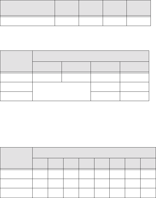
Reader-to-Micro Wiring Distance
Table 1: Model 260 Current and Cable Distance
Cable Distance
Supply
Voltage 12 VDC 13.6 VDC 24 VDC
Current 18 AWG 22 AWG 18 AWG 22 AWG 18 AWG 22 AWG
Distance
230 mA
@12 VDC
928 ft.
(283 m)
390 ft.
(119 m)
1,423 ft.
(434 m)
597 ft.
(182 m)
4,649 ft.
(1,417 m)
1,949 ft.
(594 m)

14 GE Contactless Medium Read-Range Reader Model 260
Wiring
Table 2: Reader 12-Position Field Wiring Connector
Pin Definition
1 Micro control, reader beeper (option)
2 Ground
3 8 VDC to 30 VDC
4 Door contact
5 Reader Data 1
6 Exit request (REX)
7 Green LED
8 Micro control, red LED (option)
9 Reserved for future use
10 Reserved for future use
11 Reserved for future use
12 Reserved for future use
GE Contactless Medium Read-Range Reader Model 260 15
Installation Notes (unless otherwise specified).
All numbered items below are referenced on the appropriate wiring diagrams
that follow.
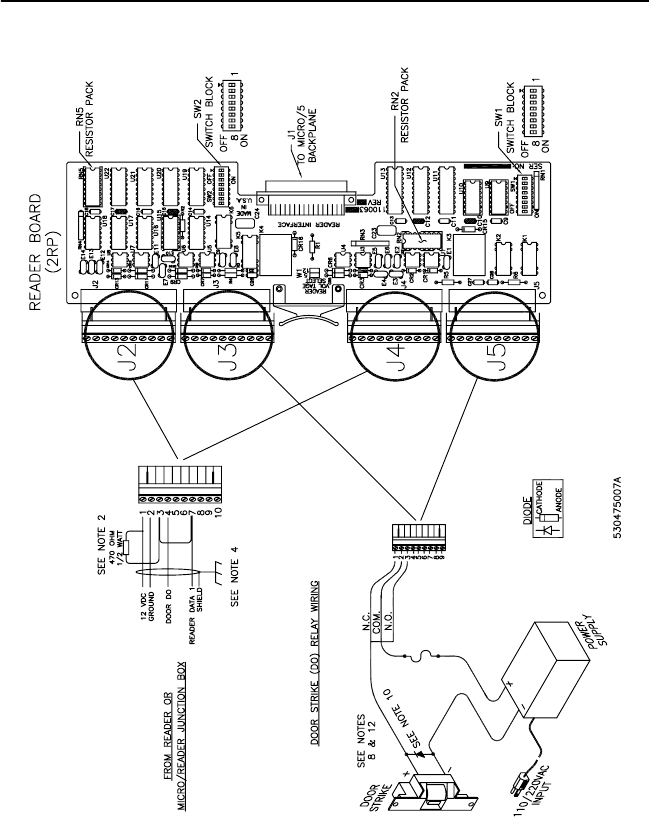
1. Fuse, power supply, door strike, protection device, and relay are provided by
the installer.
2. The 470 included Ω ½-watt resistor, must be installed at the Micro/5 2RP
terminal block. The Micro PX-2000/PXN-2000 and Micro/5 2RP and 8RP
boards do not require this resistor.
3. Shielded cable is recommended in electrically noisy environments.
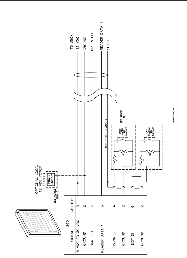
4. If using shielded cable: At the reader end: connect all shields together and
insulate them. At the Micro end: connect the shield to the micro cabinet as
indicated in the appropriate Micro Installation Manual.
5. If using a local power supply, do not connect the power (8-30 VDC) line from
the microcontroller to the reader. The ground line of the power supply must
be connected to the micro (pin 2 on the reader connector).
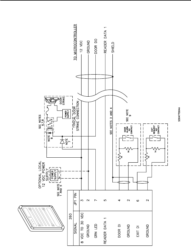
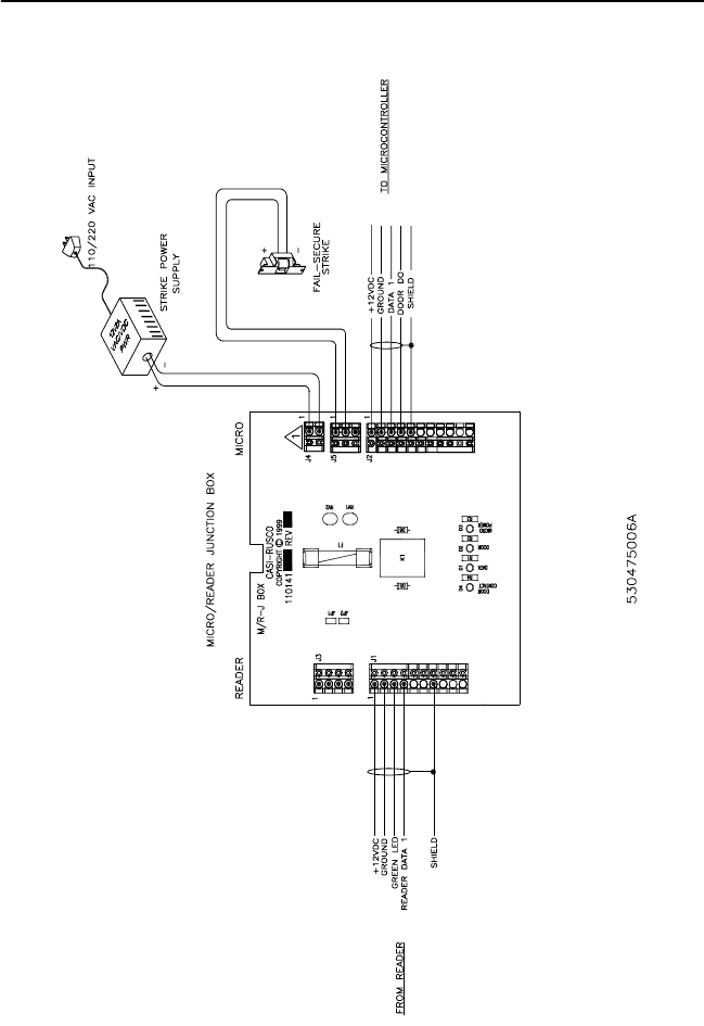
6. J3 is typically not used in this installation. See Figure 13, “GE Model 260
Reader to Micro/Reader Junction Box and Microcontroller,” on page 22.
7. Blocking diodes may be 1N4148 or equivalent (installer supplied) and located
in a secure area.
8. Protection diodes may be 1N4002, 1N4003, or 1N4004 (installer supplied) for
the door strike assembly.
9. Install two 1k Ω ¼-watt resistors (installer-supplied) at Door DI and Exit DI,
as shown.
10. Connect a protection device across the door strike.
AC Door Strikes: Connect an MOV (metal oxide varistor) across the door
strike. (Included with Micro/5 2RP, 8RP, and PX(N)-2000).
DC Door Strikes: Connect a diode across the door strike (cathode to positive
side of door strike). (Included with Micro/5 2RP, 8RP, and PX(N)-2000).
11. Relay Coil Current Restriction (Micro/5 2RP with external relay).
The relay coil current must be limited to 40 mA to prevent damage to the
board. Verify that the relay coil requires less than 40 mA.
12 VDC relay: coil resistance must be greater than 300 Ω.
The Micro/5 2RP with internal or AUX DO relay current through the relay
contacts must be limited to less than 2 A to prevent damage to the 2RP.
Current limiting may be achieved by using either a current-limiting power
supply or by wiring in an external fuse.
12. Connect protection diode across relay coil. Connect a diode across the relay
coil (cathode to positive side of relay coil).
General note: Pair wires as shown in all wiring diagrams.
16 GE Contactless Medium Read-Range Reader Model 260
Point-to-Point Wiring Diagrams
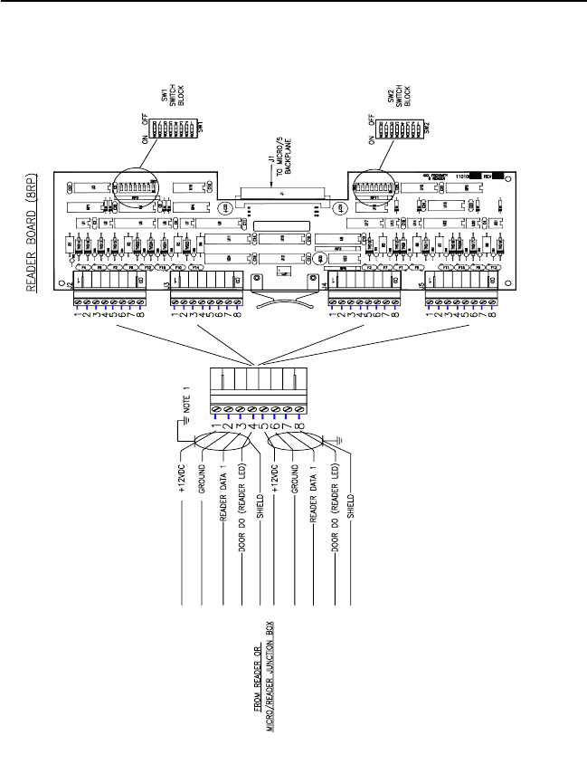
FIGURE 9: GE Model 260 Reader Wiring Diagram to Micro/5 8RP
GE Contactless Medium Read-Range Reader Model 260 17
FIGURE 10: GE Model 260 Reader Wiring Diagram to J-Box
18 GE Contactless Medium Read-Range Reader Model 260
FIGURE 11: GE Model 260 Reader to 2RP

GE Contactless Medium Read-Range Reader Model 260 19
Table 4: Reader Board 2RP Address Settings
Note: Switches SW2-5, 6, 7, and 8 are not used.
Jumper W1 RN2 and RN5 (labeling)
Set to 12 V Use 2k Ω (202) resistor packs
Table 3: 2RP Reader Switch Settings
Reader Technology and
Format SW-1 SW-2 SW-3 SW-4
Supervised F/2F ON OFF ON OFF
Reader
Board
SW 1 SW 2
56781234
1 ON OFF OFF OFF ON OFF OFF OFF
2 OFF ON OFF OFF OFF ON OFF OFF
3 OFF OFF ON OFF OFF OFF ON OFF
4 OFF OFF OFF ON OFF OFF OFF ON
20 GE Contactless Medium Read-Range Reader Model 260
FIGURE 12: GE Model 260 to 8RP
530475004A
GE Contactless Medium Read-Range Reader Model 260 21
Note: the 8RP Reader appears to the Microcontroller as four 2RP
boards.
Table 5: 8RP Reader Technology and Format
Reader Technology and
Format SW1-1 SW1-2 SW1-3 SW1-4
Supervised F/2F ON OFF ON OFF
Table 6: 8RP Board Address Settings
Board Type
SW 1
5 6 7 8
Standard ON ON ON OFF
Board 1a
a. Readers 1 - 8.
Does not apply. OFF ON
Board 2b
b. Readers 9 - 16.
OFF ON
Board Type
SW 2
12345678
Standard OFF OFF ON ON ON OFF ON OFF
Board 1a
a. Readers 1 - 8.
ON OFF ON OFF ON OFF ON OFF
Board 2b
b. Readers 9 - 16
ON ON OFF OFF OFF ON OFF ON
22 GE Contactless Medium Read-Range Reader Model 260
FIGURE 13: GE Model 260 Reader to Micro/Reader Junction Box
and Microcontroller

GE Contactless Medium Read-Range Reader Model 260 23
Troubleshooting
If the operation of a component is in doubt, substitute a known-good
component and retry the system. Always verify wiring against the
provided wiring information before powering up the reader.
Table 7: Error Conditions and Possible Solutions
Condition Possible Solutions
None of the
LEDs are on.
Present a known-good ISO 15693 or ISO 14443A
type card to the reader while listening for the
beeper. If the beeper sounds, the reader is faulty
and should be replaced. If the beeper does not
sound, check the following:
•Power connections to the reader
•Reader supply voltage at connector JP1 pin 3
and that the ground connection JP1 pin 2 is
secure
The green LED is
always on. The
green LED indi-
cates that the
door strike is
open. It is con-
trolled by the
input on connec-
tor JP1 pin 7.
Disconnect the wire on JP1 pin 7. If the green LED
stays on, the reader is faulty and should be
replaced. If the green LED goes off, then the prob-
lem is most likely not in the reader.
Reconnect the wire on JP1 pin 7 and measure the
voltage at JP1 pin 7. A low voltage (0 to 2 VDC)
turns on the green LED. If the voltage is low, there
are two possibilities:
•A short to ground in the wiring between the
reader and microcontroller, or
•The host system may be energizing the door
strike
The door does
not open and the
green LED does
not light when an
ISO 15693 or
ISO 14443A card
is presented.
Verify that the door strike and the green LED are
wired correctly.
Verify that the access card has been entered and
that the reader has been properly configured in
the host system.

24 GE Contactless Medium Read-Range Reader Model 260
The green LED
does not light,
but the door
strike unlocks the
door when a valid
ISO 15693 or
ISO 14443A card
is presented.
Verify that the door strike is wired correctly. Refer
to the appropriate wiring diagram.
Disconnect the wire from JP1 pin 7 (green LED)
and connect JP1 pin 7 to JP1 pin 2 (ground). If the
green LED is now on, the reader is good and the
connection to the reader is defective. If the green
LED does not light, replace the reader.
Green LED lights
but the door does
not open.
Verify correct door strike wiring and operation. The
reader is functioning. If not, check that the block-
ing diode is functioning. If it is not, replace it.
Reader sounds a
short triple beep
every 30 seconds
and the red LED
flashes slowly
(every 2 sec-
onds).
The reader has lost communication with the micro-
controller.
Check the reader-to-microcontroller wiring, in par-
ticular, the terminations for Reader Data 1. Refer
to the appropriate wiring diagram. Verify that the
2RP AUX DO is jumpered to the reader data 1 on
the microcontroller. Jumper between 2RP JP2 and
JP4, pins 3 and 7.
Verify that the correct pull-up resistor is installed
on the microcontroller (470 Ω ½-watt, 2RP JP2
and JP4, pins 1 and 3).
Verify that the microcontroller has the correct firm-
ware. Refer to the manual that came with your
microcontroller for instructions.
Try the reader on a different reader input port at
the microcontroller. If this corrects the problem,
the operational status of the original port is sus-
pect.
Replace the reader with one you know is working
correctly. If this corrects the problem, then the
reader is probably faulty and should be replaced.
If none of the above steps have identified the
problem, there may be a significant noise source
present in the installation which is interfering with
the reader-to-microcontroller communications. If
this is the case, use shielded wire for reader-to-
microcontroller connections.
Condition Possible Solutions

GE Contactless Medium Read-Range Reader Model 260 25
The reader
sounds a short
triple beep every
30 seconds and
the red LED
flashes quickly
(every 400 ms).
Indicates a tamper violation. Ensure the reader is
properly attached to its backplate. The red LED
will continue to blink for 30 seconds. The reader is
ready for use when the yellow LED is steadily on.
The reader
sounds a short
triple beep every
5 seconds and
the red LED
also flashes
every 5 seconds.
Check that the 4-state supervised switches are
connected with two 1K Ω resistors to the door con-
tact and the exit request inputs or, if the inputs are
not used, that resistors are installed at the reader
connector:
DI: Pins 2 and 4, 1K Ω
REX: Pins 2 and 6, 2K Ω
A 470 Ω ½-watt pull-up resistor is required
between 12 VDC and Reader Data 1 on the Micro/
5 2RP (only).
Condition Possible Solutions

26 GE Contactless Medium Read-Range Reader Model 260
Technical Specifications
• Cable: Belden (shielded) 8777, 9873, 9773
• Agency Certifications: FCC Part 15; CE Mark, and UL 294 (pending)
• Color: Gray
• Dimensions with backplate (HWD): 11.75” x 11.75” x 1.16” (298.45 x
298.45 x 29.46 mm)
• Environmental: Interior or Exterior
• Humidity Range: 0 to 95%, non-condensing
• Input Voltage Range: 8 to 30 VDC
• Index of Protection: IP 65 (IEC 529)
• Microcontroller Communications: F/2F supervised door input, REX,
and reader communication/power monitoring
• Minimum Wiring: 4 conductors
• Operating Temperature/Range: -20 to 158o F (-29 to 70o C)
• Read Range:
• 14 in. (355,6 mm) maximum for ISO 15693
• 7 in. (177.8 mm) maximum for ISO 14443A
• Weight: 2.35 lbs. (1.06 kg)
Table 8: Current and Cable Distance
Cable Distance
Supply
Voltage 12 VDC 13.6 VDC 24 VDC
Current 18 AWG 22 AWG 18 AWG 22 AWG 18 AWG 22 AWG
Distance
230 mA
@12 VDC
928 ft.
(283 m)
390 ft.
(119 m)
1,423 ft.
(434 m)
597 ft.
(182 m)
4,649 ft.
(1,417 m)
1,949 ft.
(594 m)

GE Contactless Medium Read-Range Reader Model 260 27
Table 9: Functional Specifications
International
Standards
ISO 15693 and ISO 14443A
Microcontroller
compatibility
• Micro/5-PX and Micro/5-PXN with 2RP and 8RP
processor boards (incompatible with M/5 and
2SRP board configurations)
• Micro/PX-2000 and Micro/PXN-2000
Status Indicators Red, Yellow, and Green LEDs and Beeper
28 GE Contactless Medium Read-Range Reader Model 260
Regulatory Notices
FCC
Changes or modifications not expressly approved by GE-Interlogix for
compliance could void the user’s authority to operate the equipment.
FCC and CE Compliance.
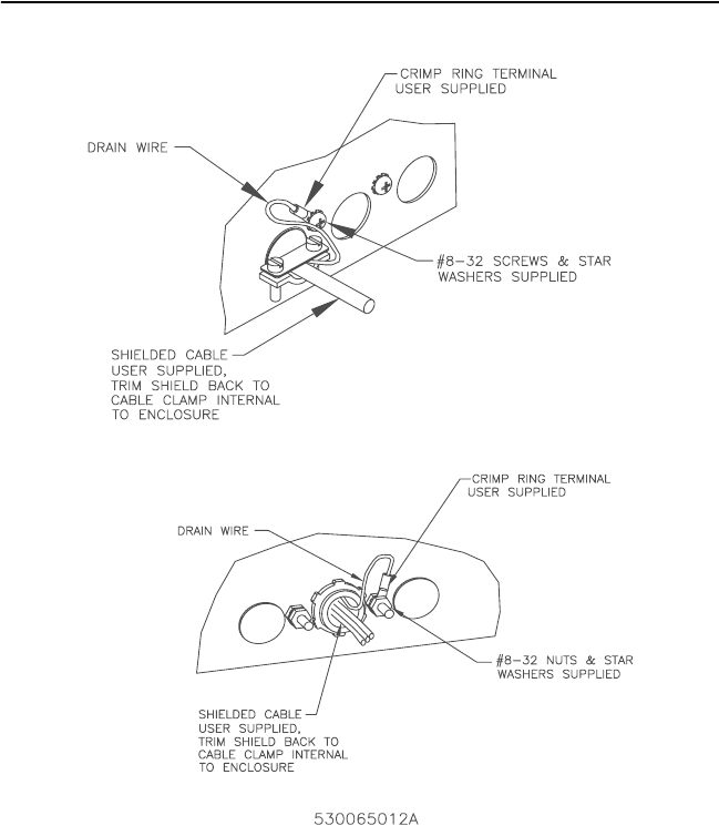
Shield grounds must be stripped back through the knockout hole (strain
relief) and grounded to the external ground stud provided on the
microcontroller.
FIGURE 14: Stripping of Shield Grounds

GE Contactless Medium Read-Range Reader Model 260 29
CE Manufacturers Declaration
of Conformity
Manufacturer’s
Name: CASI-RUSCO
Manufacturer’s
Address:
791 Park of Commerce Boulevard, Suite 100
Boca Raton, FL USA 33487
EU Representative: Interlogix Europe & Africa
Excelsiorlaan 28
B- 1930 Zaventum
Belgium
Product
Identification:
Product: GE Interlogix-CASI Medium Read-Range
Reader
Model Number: 260
Brand: CASI
Means of Conformity: • Hereby, CASI-RUSCO, declares that this
equipment is in compliance with the essential
requirements and other relevant provisions of
Directive 1999/5/EC.
• Hierbij verklaart CASI-RUSCO dat het apparoat
in overeenstemming is met de essentiële eisen
en de andere relevante bepalingen van richtlijn
1999/5/EG.
• Par la présente CASI-RUSCO déclare que
l'appareil est conforme aux exigences
essentielles et aux autres dispositions
pertinentes de la directive 1999/5/CE.
• Hiermit erklärt CASI-RUSCO, dass sich diese
Ausrüstung in Übereinstimmung mit den
grundlegenden Anforderungen und den
anderen relevanten Vorschriften der Richtlinie
1999/5/EG befindet". (BMWi)
Notices: Approved for use in the following countries:
A
B
DK
FIN
IS
IRL
GR
D
I
NL
F
CZ
H
LU
N
PL
P
E
S
CH
GB
30 GE Contactless Medium Read-Range Reader Model 260
GE Contactless Medium Read-Range Reader Model 260 31
32 GE Contactless Medium Read-Range Reader Model 260