Deister Electronic SWH4500 Proximity Reader User Manual SWH 4x00 install guide
Deister Electronic GmbH Proximity Reader SWH 4x00 install guide
User Manual
1
Model SWH-4x00
Contactless Multi-Technology
125 KHz and 13.56 MHz Reader
Installation Guide
Version D0
Part Number UM-090
January 2007

2
CONTENTS
Introduction . . . . . . . . . . . . . . . . . . . . . . . . . . . . . . . . . . . . . . . . . . . . . . . . 3
Features . . . . . . . . . . . . . . . . . . . . . . . . . . . . . . . . . . . . . . . . . . . . . . . . . . . 4
Mounting . . . . . . . . . . . . . . . . . . . . . . . . . . . . . . . . . . . . . . . . . . . . . . . . . . 5
Installation Considerations. . . . . . . . . . . . . . . . . . . . . . . . . . . . . . . . . . . . . 6
Wiring . . . . . . . . . . . . . . . . . . . . . . . . . . . . . . . . . . . . . . . . . . . . . . . . . . . . 8
Installation Notes . . . . . . . . . . . . . . . . . . . . . . . . . . . . . . . . . . . . . . . . . . . . 9
Troubleshooting . . . . . . . . . . . . . . . . . . . . . . . . . . . . . . . . . . . . . . . . . . . . 10
Model SWH-4x00 Technical Specifications . . . . . . . . . . . . . . . . . . . . . . .11
FCC Digital Device Limitations . . . . . . . . . . . . . . . . . . . . . . . . . . . . . . . 13
UL Standards Compliance. . . . . . . . . . . . . . . . . . . . . . . . . . . . . . . . . . . . 14
CE Marking . . . . . . . . . . . . . . . . . . . . . . . . . . . . . . . . . . . . . . . . . . . . . . . 15

3
INTRODUCTION
The SWH-4100 and SWH-4200 Contactless readers will read Prox and
Smart Cards at frequencies of both 125 kHz and 13.56 MHz. The reading
capability includes, for Smart Cards, both unencrypted serial numbers and
encrypted MIFARE® programmed sectors. Refer to Table 1 for a complete
list of compatible standards and data.
The SWH-4200 reader has a built-in keypad with 12 keys, including CMD/
ENTER and CE (Clear Entry). The reader outputs the PIN code in the 8-bit
burst Wiegand. It also has the ability to read and verify the PIN on a Smart
Card. This feature is eanbled with the use of program cards. Please contact
Software House for more information on the PIN-on-Card function.
TABLE 1. Compatible Credential Formats - Model SWH-4100
HID® 26 Bit ISO 14443A (MIFARE®) Sector
HID® Corporate 1000 ISO 14443B Serial Number
HID® 36 Bit Wiegand ISO 15693 Serial Number
HID® 37 Bit Wiegand MIFARE® Sector
Other HID pass through formats DESFire® Serial Number
deister Prox SmartFrame® iCLASS® Serial Number
CASI-RUSCO® Prox Lite Others - Future Expansion

4
FEATURES
Universal compatibility with most 125 kHz Prox (including all HID®
Prox formats), all ISO 15693, and ISO 14443A credentials (badges, disk
tags and key fobs). Reads both 125 kHz and 13.56 MHz credentials in
the same reader.
Electrical protection (reverse polarity diode protection on power lines).
Data lines: high-speed transient voltage suppressor diodes.
IP65-rated sealed electronics for deployment in both interior and
exterior environments.
Integrated reader tamper protection.
5
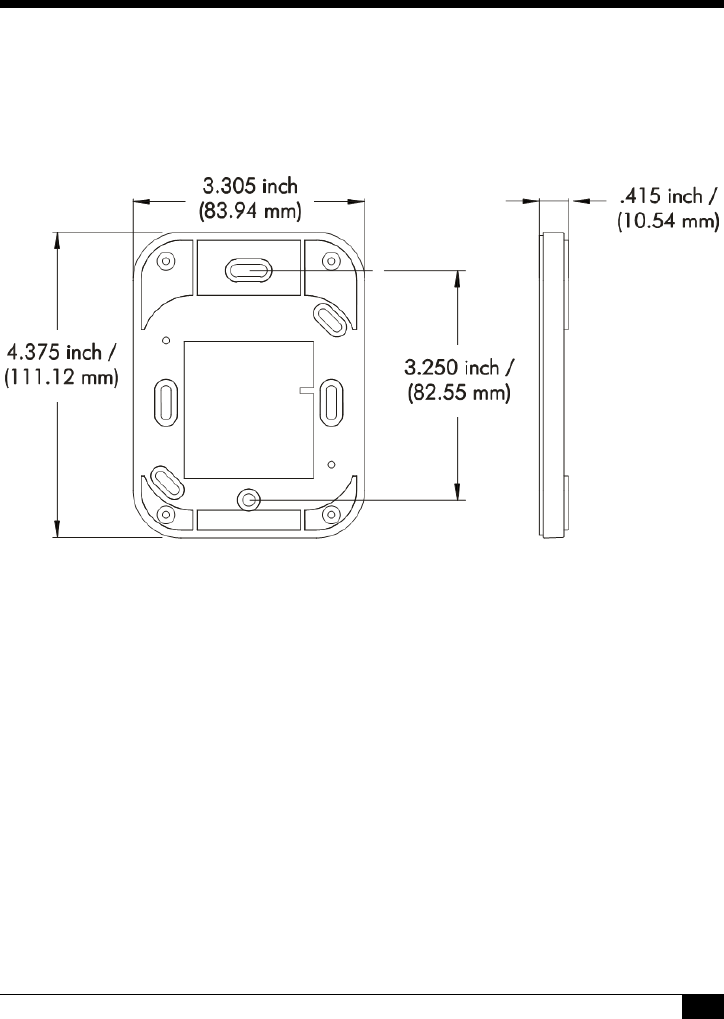
MOUNTING
Mount the single-gang backplate (with tamper magnet installed) onto the
wall.
FIGURE 1. Model SWH-4x00 Reader Backplate
(includes tamper switch magnet)
NOTE
Mounting holes fit standard U.S. single-width electrical box and
standard European (EMEA) electrical box hole patterns.
Mount the reader module directly to the backplate and then snap the front
cover in place as indicated in Figure 2.
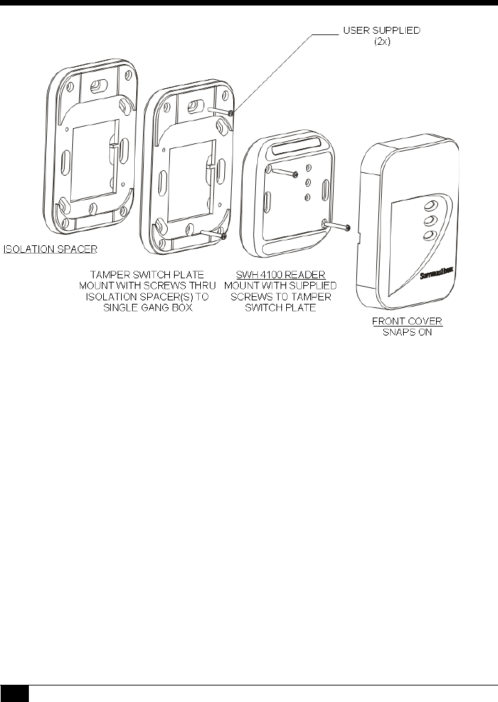
6
FIGURE 2. Mounting Assembly
(including 1 optional isolation spacer)
Please note that Figure 2 shows the SWH-4100 reader and cover plate.
Although the SWH-4200 keypad reader and front cover plate differ, the
mounting assembly is the same as the SWH-4100.
INSTALLATION CONSIDERATIONS
An isolation spacer (available from Software House, part number
SWH-ISOSPC) may be used to improve the read range distance when
mounting the reader to a metal surface. To optimize reader range, use the
number of backplates as indicated in Table 2. Use of Isolation Spacers is
optional and not required for non-metal mounting surfaces.

7
Installation of two SWH-4x00 readers side-by-side
and back-to-back
Read range is not affected if the center-to-center distance between two
readers is greater than or equal to four (4) inches (101.6 mm). Two readers
can simultaneously read the same badge or tag if the distance between the
two readers is less than 4 inches, center-to-center. If the distance between
the two readers is less than four inches, field interference between the two
readers may result in a double-badge read.
NOTE
If two readers are being placed back-to-back on a wall less
than 4 inches thick, maximum performance can be achieved
by using a metal separation plate and then using isolation
spacers as necessary.
TABLE 2. Isolation spacer recommendation
for mounting the SWH-4x00 reader on metal
Distance Reading Distance
No metal plate 100%
4.5 cm 100%
2.7 cm (3 tamper plates) 85%
1.8 cm (2 tamper plates) 70%
0.9 cm (1 tamper plate) 50%
0 cm 10%
8
WIRING
SWH-4x00 models have twelve terminals as noted in Table 3. The terminal
strip is removable for easy installation and wiring. When attaching wires to
the connector, strip off only the minimum insulation required (approx. 1/
8'') and push the wire into the connector until the insulation is flush or
inside the connector body. This is particularly critical for outdoor readers.
While the reader itself is designed and protected to IP65 standards, the
cable wires can potentially corrode and short together if not carefully
mounted and tightly fastened in the connector body.
Table 4 indicates maximum wiring distances per Wiegand standard with
the three most common gauges of cable.
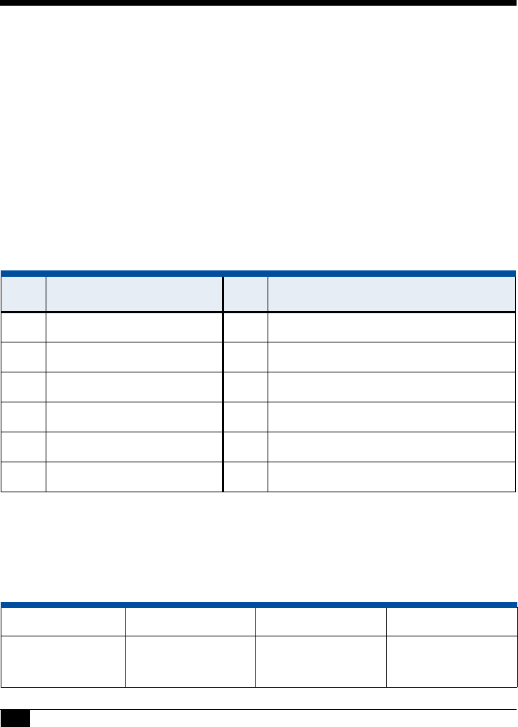
TABLE 3. Connector Pins for Model SWH-4x00
Pin Description Pin
1 External Beeper Control 7 External Green LED Control
2 Ground 8 External Red LED Control
3 Power (8 to 16 VDC) 9 A - RS485 - used for Flash upgrade
4 D1 Wiegand 10 B - RS485 - used for Flash upgrade
5 D0 Wiegand 11 Tamper (Normally Closed)
6 Reserved for Future Use 12 Tamper (Normally Closed)
TABLE 4. Maximum cable distance for 18, 20, or 22 AWG wire
Wire Gauge 18 AWG 20AWG 22 AWG
Cable
Distance 500 feet
(152 meters) 300 feet
(91 meters) 200 feet
(61 meters)
9
INSTALLATION NOTES
Unless otherwise specified in this manual, please follow these guidelines:
1. Shielded cable is recommended in electrically noisy environments.
2. You can use a local power supply for the reader. If so, don’t connect the
power supply from the controller to the reader. The ground line of the
local power supply must be connected to the power supply of the
controller.
3. The unit needs to be operated with a power source with limited power
consumption according to EN 60950-1 (2001) paragraph 2.5.
Das Gerät ist mit einer Stromquelle mit begrenzter Leistung nach EN
60950-1 (2001) Absatz 2.5 zu betreiben.
4. Use of a pull-up resistor may be required by some controllers. Consult
your controller manual.
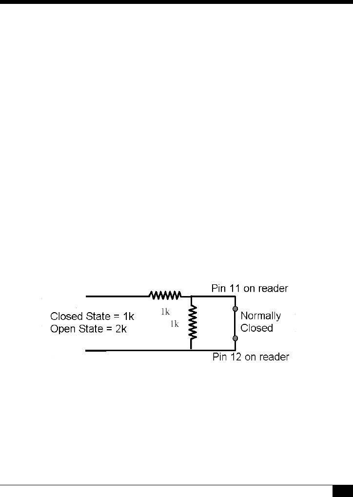
5. For tamper wiring, connect Pins 11 and 12 to a normally closed
supervised input, as shown in Figure 3.
FIGURE 3. Normally Closed Wiring for Reader Tamper

10
TROUBLESHOOTING
If the operation of a component is in doubt, substitute a known good
component and retry the system. Always verify wiring against the provided
wiring information before powering up the reader.
TABLE 5. Error Conditions and Possible Solutions
Condition Possible Solutions
None of the LEDs
are on. Check the following:
Power connections to the reader.
Reader supply voltage at connector pin 3 and
that the ground connection pin 2 is secure and
well connected.
The door does not
open and the green
LED does not light
when a qualified
credential is
presented.
Verify that the door strike and the green LED are
wired correctly. Verify that the access credential
has been entered and that the reader has been
properly configured in the host system.
The green LED
does not light but
the door strike
unlocks the door
when a valid
credential is
presented.
Verify that the door strike is wired correctly. Refer
to the appropriate wiring diagram in your
controller manual. Disconnect the wire from pin 7
(green LED) and connect pin 7 to pin 2 (ground). If
the green LED is now on, the reader is good and
the connection to the reader is defective. If the
green LED does not light, replace the reader.

11
MODEL SWH-4X00 TECHNICAL
SPECIFICATIONS
Cable Recommendations: 4 core (minimum), shielded, 22 AWG
(minimum) cable.
Connectors: 12 position, 3.5 mm Screw Terminals -
Plug-In
Certifications: FCC Part 15, CE and UL 294
Open Standards
Compliance: ISO 14443A
ISO 14443B (Depending on specific
implementation)
ISO 15693 (including some partially
compliant credentials)
Other Standards
Compliance: deister SmartFrame® in both 125 kHz and
13.56 MHz implementations
HID® Prox at 125 kHz (All Formats)
PIN Code Entry Keys
(Model SWH-4200 only) Twelve PIN code entry keys 0-9,
Command/Enter, and CE (Clear Entry)
Standard Color: Black (other colors available; contact your
Software House representative)
Dimensions with backplate
(height/width/depth): 4.37" × 3.31" × 1.10"
(110.99 × 84.07 × 27.94 mm)
Power Supply Rated Voltage: 9.4-16 VDC 125 mA
maximum current
Note: Unit has been tested and is reliable
operating to 8 VDC on long lines.

12
Environments: Meets UL 294 standards for Outdoor Use
Humidity: 5 to 90% (non-condensing)
Operating Temperature: -31º F to 151º F (-35º C to 67º C)
Index of Protection: IP 65 (IEC 529)
Read Range: 1 to 5 inches depending on credential
technology and environment.
Note: Read range for credentials of
identical technologies may vary greatly
depending on the tuning and antenna
structure of each individual credential.
Standard Wiegand Output
including: ID Pass-Through Option
Serial Number Read
Fixed Wiegand bit stream option
SmartFrame® encrypted MIFARE Sector
read and conversion to Wiegand. Consult
your Software House representative for
available reconfiguration cards for your
reader.
8-bit burst Wiegand PIN code (Model
SWH-4200 only)
PIN-on-card featured (Model SWH-4200
only)
Upgrade Complete upgrade capability using RS485
port for reflashing of internal ROM.
RS485 output option Available for compatible controllers.

13
FCC DIGITAL DEVICE LIMITATIONS
Radio and Television Interference
This equipment has been tested and found to comply with the limits
for a digital device, pursuant to Part 15 of the FCC rules. These limits
are designed to provide reasonable protection against harmful
interference when the equipment is operated in a commercial
environment. This equipment generates, uses, and can radiate radio
frequency energy and, if not installed and used in accordance with the
instruction manual, may cause harmful interference to radio
communications. Operation of this equipment in a residential area is
likely to cause harmful interference, in which case the user will be
required to correct the interference at his own expense.
This device complies with Part 15 of the FCC rules. Operation is
subject to the following two conditions: (1) This device may not cause
harmful interference, and (2) this device must accept any interference
received, including interference that may cause undesired operation.
In order to maintain compliance with FCC regulations, shielded cables
must be used with this equipment. Operation with non-approved
equipment or unshielded cables is likely to result in interference to
radio and television reception.
CAUTION: Changes or modifications not expressly approved by
the party responsible for compliance could void the user’s authority to
operate this equipment.

14
CANADIAN RADIO EMISSIONS
REQUIREMENTS
This digital apparatus does not exceed the Class A limits for radio noise
emissions from digital apparatus set out in the Radio Interference
Regulations of the Canadian Department of Communications.
Le present appareil numerique n'emet pas de bruits radioelectriques
depassant les limites applicables aux appareils numeriques de la class A
prescrites dans le Reglement sur le brouillage radioelectrique edicte par le
ministere des Communications du Canada.
UL STANDARDS COMPLIANCE
This reader has been tested by Underwriters Laboratories, Inc. for standard
UL 294, Access Control System Units, but has not been tested for
compliance with any particular model of controller.
UL has not evaluated the RS-485 Output of this reader.

15
CE MARKING
Hereby, Software House declares that this equipment, if used according to
the instructions, is in compliance with the essential requirements and other
relevant provisions of the RTTE Directive 1999/5/EC. For use in all
countries of the EU.
A Declaration of Conformity exists for the following Software House
Multi-technology readers:
To obtain a copy, contact Software House and request the “Declaration of
Conformity” document for Multi-technology readers.
Software House
70 Westview Street
Lexington, MA 02421 U.S.A.
In case of alteration of the product, not agreed to by us, this declaration will
lose its validity.
SWH-4100 SWH-2100 SWH-1100 SWH-2000
SWH-5100 SWH-4200 SWH-3100 SWH-4500
SWH-1000 SWH-3000 SWH-5000
This symbol indicates proof of conformity to
applicable European Economic Community
Council directives and harmonized standards
published in the official journal of the European
Communities.

Software House
70 Westview Street
Lexington, MA 02421
http://www.swhouse.com
Fax: 781-466-9550 Phone: 781-466-6660
#896023
16
Copyrights and Trademarks
This document contains proprietary information of Tyco International, Inc. and is furnished to its
customer solely to assist in the installation, testing, operation and maintenance of the equipment
described. This document may not be reproduced in whole or in part without the written approval of
Tyco International.
Copyright 2005 Tyco International
All rights reserved.
Printed in Germany.
Software House is a trademark of Sensormatic Electronics Corporation.
MIFARE, SmartFrame, HID, DesFire, iCLASS, and CASI-RUSCO are registered trademarks of
other companies not affiliated with Sensormatic.