Deister Electronic UDL500 UHF RFID Reader User Manual
Deister Electronic GmbH UHF RFID Reader
User Manual

UDL500
Wiring & Installation
Instructions
V17/01/08

© Copyright 2008 by deister electronic GmbH
All rights reserved. No part of this publication may be reproduced, stored in a retrieval
system, or transmitted, in any form or by any means, electronic, mechanical, photocopying,
recording, or otherwise, without prior written permission of deister electronic GmbH.
deister electronic GmbH reserves the right to make changes to any and all parts of this
documentation without obligation to notify any person or entity of such changes.
January 2008 SK/IO/BF
deister electronic GmbH
Hermann-Bahlsen Str. 11
30890 Barsinghausen
Germany
Phone: +49 (0) 51 05 - 51 61 11
Fax: +49 (0) 51 05 - 51 62 17
E-Mail: info@deister-gmbh.de
Web: www.deister.com
2deister electronic GmbH 30890 Barsinghausen Germany V17/01/08
Wiring & Installation Instructions UDL500

Content
1. Technical Data............................................................4
2. Connectors...................................................................5
2.1 Installation note..................................................................................................5
2.2 Pin assignment UDL500.......................................................................................6
2.3 UDL500: RS485 interface....................................................................................6
2.4 UDL500: Control digital output via hardware trigger..............................................7
2.5 UDL500: Control digital output via software trigger................................................8
3. RS485 interface...........................................................9
4. Mechanical dimensions.............................................10
4.1 UDL500 housing...............................................................................................10
5. Transmission protocol...............................................11
6. Mounting...................................................................11
6.1 Mast/Tube mounting.........................................................................................11
6.2 Extended mast holding device LRM2 ..................................................................13
6.3 Wall mounting with link holder LRM1..................................................................14
6.4 Fixing link holder LRM1.....................................................................................14
6.5 Function principle and environmental influences...................................................15
6.6 Radiation pattern of the transmitting antenna.......................................................16
7. Configuration software.............................................20
7.1 SNG3 interface converter..................................................................................20
7.2 Configuration...................................................................................................21
7.3 Parameters.......................................................................................................22
7.3.1 Basic Setup..............................................................................................22
7.3.2 Frequency Setup......................................................................................24
7.3.3 Mode Control..........................................................................................25
7.3.4 Trigger....................................................................................................27
7.3.5 Selection Settings.....................................................................................28
7.3.6 Selection Mask.........................................................................................29
7.3.7 Prog data................................................................................................30
7.4 LEDs and Beeper...............................................................................................30
8. Portal application with DCU1 Data Control Unit......31
9. Accessories of the UHF product family......................32
10. Regulatory Notices..................................................33
10.1 Europe...........................................................................................................33
10.2 FCC Digital Device Limitations.........................................................................33
10.3 FCC Notice....................................................................................................34
10.4 FCC Radiation Exposure Statement...................................................................34
10.5 Industry Canada.............................................................................................34
V17/01/08 deister electronic GmbH 30890 Barsinghausen Germany 3
Wiring & Installation Instructions UDL500

1. Technical Data
Dimensions (mm): 640 x 280 x 75
Housing material: ABS/PMMA, ALUMINUM, V2A
Color: silver
Protection class: IP65
Operating temperature: -20 ... +70°C
Storing temperature: -40 ... +85°C
Relative humidity: 5% ... 95% non condensing
Voltage supply: 10 ... 30V/DC
Power consumption: 10W (during operation)
2W (standby)
Transmission frequency: 865 – 868MHz (EU)
902 – 928MHz (USA)
Writing-/reading distance: up to 5m, depending on type of transponder
and the local environment
Antennas: 2 patch antennas (transmitting and receiving antennas)
Polarization: circular
Radiated output power: 2W ERP (ETSI EN 302 208) or 4W EIRP
(FCC Part 15), configurable in 10 steps
Transponder protocol: ISO 18000-6 Type C
EPC Class1 Gen2
optional:
ATMEL ATA 5590 (TAGIDU),
EM 4022, 4222, 4422
Trigger Input: 8 ... 36V/DC
Digital Output: 6 ... 32V/DC (I<500mA)
32 ... 48V/DC (I<300mA)
Interface: RS485
Anticollision: high-speed detection for multiple tag identification
Operating modes: single reader (stand alone), portal mode (up to 4
readers can be connected to the DCU1)
Acoustical indicator: beeper
Optical indicator: 3 LEDs (yellow, green, red)
Conformity:
Human exposure EN 50364
EMC EN 301 489
air interface (EU) EN 302 208 (listen before talk)
4deister electronic GmbH 30890 Barsinghausen Germany V17/01/08
Wiring & Installation Instructions UDL500
2. Connectors
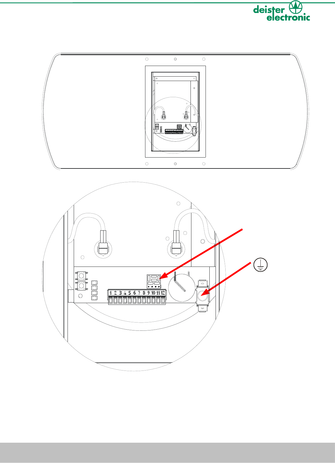
2.1 Installation note
Attention:
It is important to take care that the marked tab connector is connected to the supplied
cable plug. The device always needs to be professionally grounded using a yellow/green
flexible line with a minimum profile of 0.75mm².
V17/01/08 deister electronic GmbH 30890 Barsinghausen Germany 5
Wiring & Installation Instructions UDL500
RS485
termination
resistor
(terminator)
Tab connector
for grounding
Attention:
The procedures and working activities described in this
document are intended to be performed by technical
professionals only.
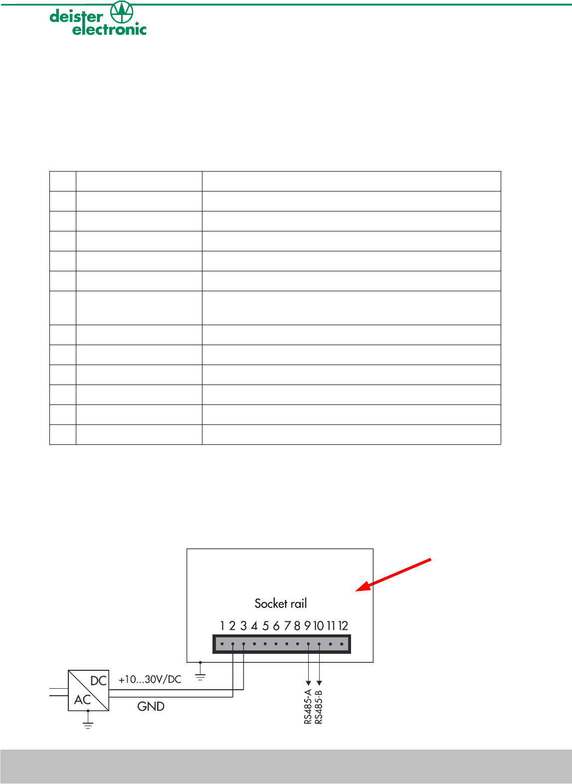
2.2 Pin assignment UDL500
Pin Name Function
1 – not connected
2 GND ground
3 +10 ... 30V/DC voltage supply +10 ... 30V/DC
4 OUTGND external ground for digital output
5 OUT digital output voltage, max. +48V/DC, I<300mA
6 OUTVCC external voltage supply for digital output, max. +48V/DC,
I<300mA
7 – not connected
8 – not connected
9 RS 485-A RS485 interface, data line A
10 RS 485-B RS485 interface, data line B
11 IN - external ground for trigger input
12 IN + external voltage supply for trigger input, max. +36V/DC
Table 1: pin assingment UDL500
2.3 UDL500: RS485 interface
Installation note: We recommend professional grounding of the device (see 2.1
Installation note).
6deister electronic GmbH 30890 Barsinghausen Germany V17/01/08
Wiring & Installation Instructions UDL500
UDL500 housing
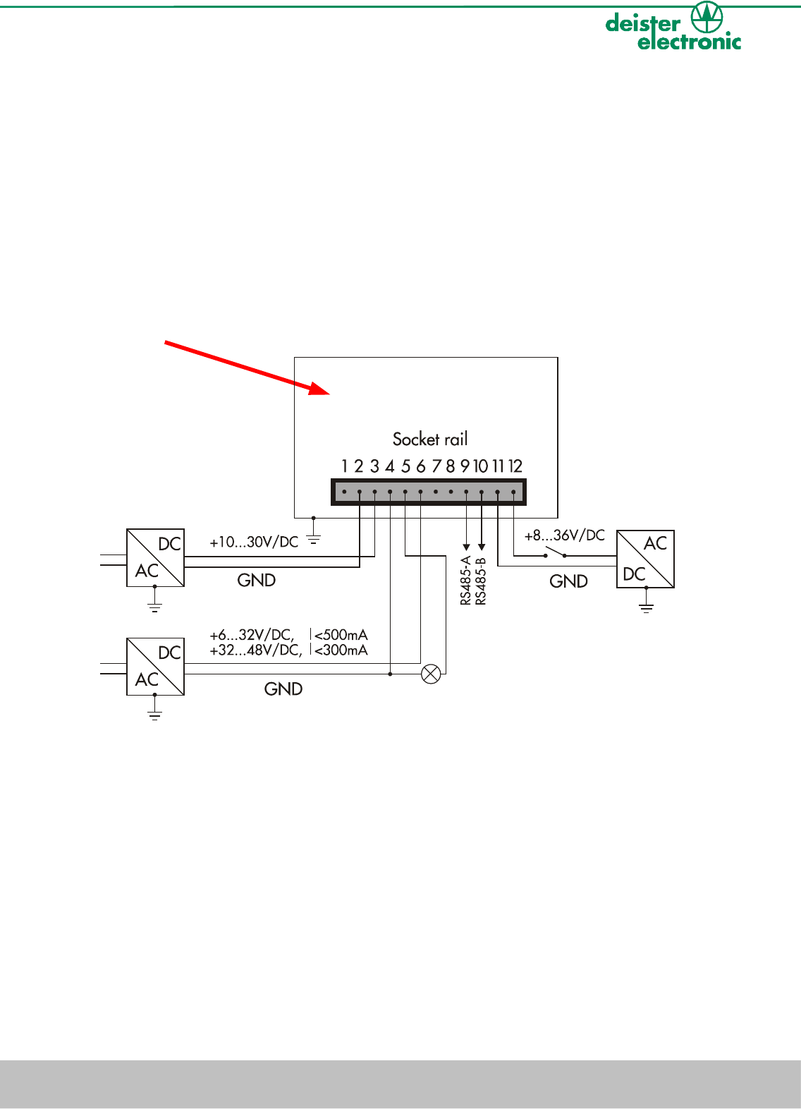
2.4 UDL500: Control digital output via hardware trigger
Installation notes: We recommend professional grounding of the device (see 2.1
Installation note). Output OUT and Input IN are potential-free. Take care that the
grounding will be sufficient (use second tab connector)!
The potential-free input IN may be used to control the reader by a hardware trigger (e.g.
tip switch). The control of the potential-free output OUT can be configured within the
software. For this the reader has to be operated in trigger mode.
In the following example of circuits, the output OUT has not been potential isolated:
UDL500 housing
V17/01/08 deister electronic GmbH 30890 Barsinghausen Germany 7
Wiring & Installation Instructions UDL500
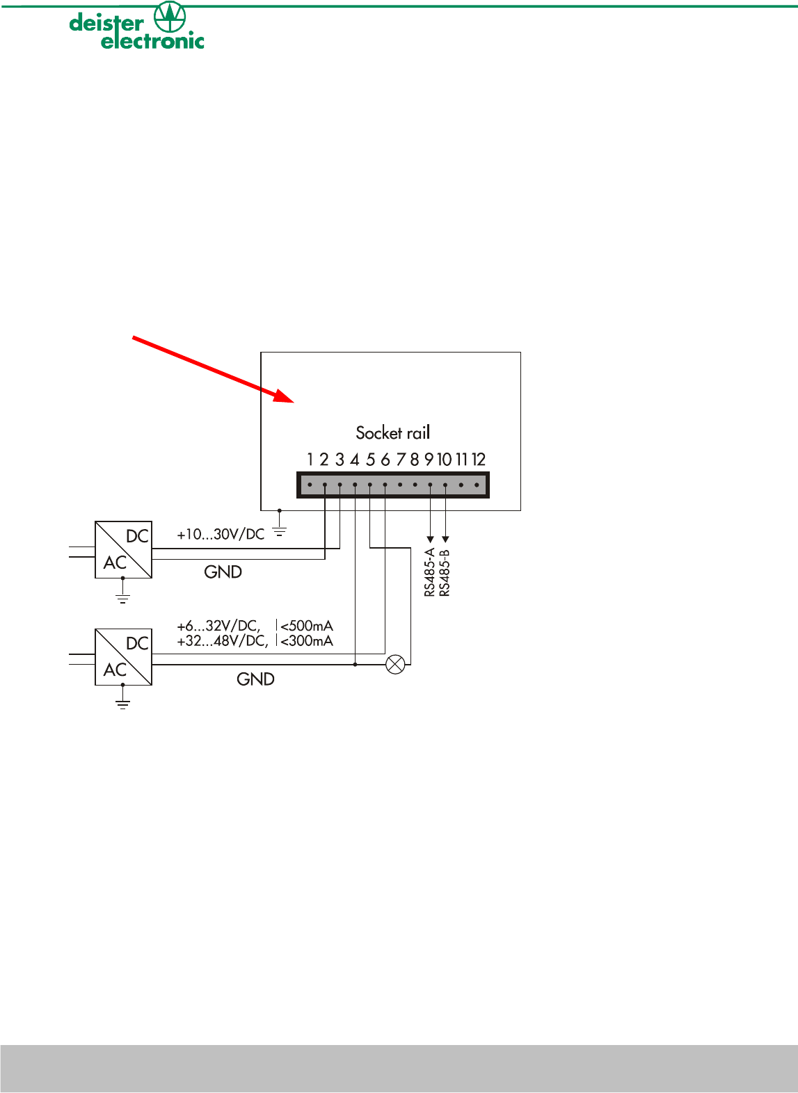
2.5 UDL500: Control digital output via software trigger
Installation notes: We recommend professional grounding of the device (see 2.1
Installation note). Output OUT is potential-free. Take care that the grounding will be
sufficient (use second tab connector)!
The reader can be controlled by a trigger signal via software. Therefore, it is not necessary
to use the potential-free input IN. The control of the potential-free OUT can be configured
within the software. For this the reader has to be operated in trigger mode.
In the following example of circuits the output has not been potential isolated:
UDL500 housing
8deister electronic GmbH 30890 Barsinghausen Germany V17/01/08
Wiring & Installation Instructions UDL500
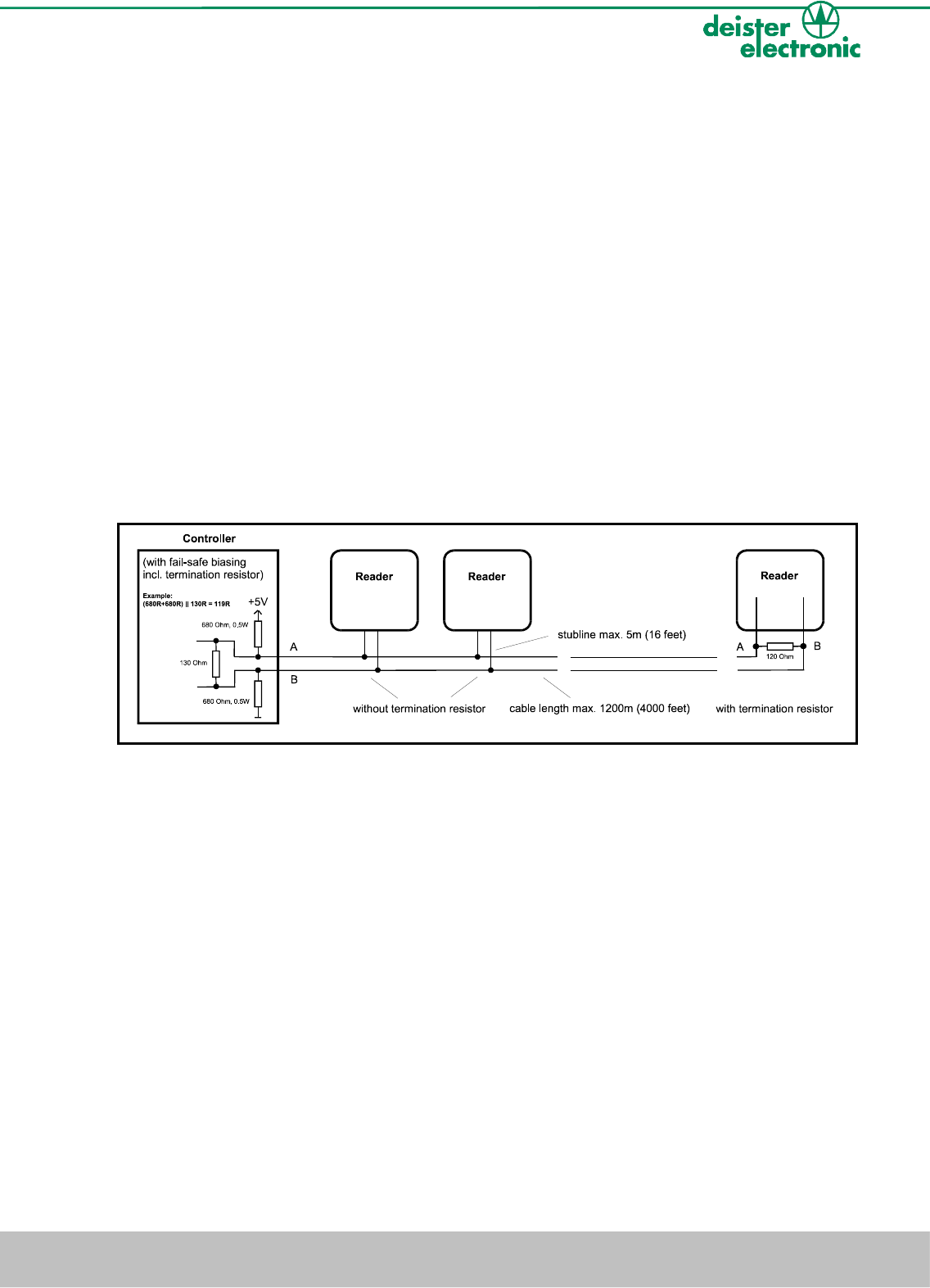
3. RS485 interface
Most RS485-buses require termination resistors across the conductor pair. The need for
termination has to be checked for each installation. Especially for high data rates, steep
edges or long cables termination resistors are absolutely mandatory. Only both ends of the
main cable, i.e. at the first and the last device, require termination resistors, additional
resistors excessively load the drivers. The resistor value matches the cable´s differential
mode characteristic impedance (in most cases 100 ... 120Ω).
Attention!
This termination resistor (Terminator, 120Ω) has been factory built-in into
all UDL500 and has to be removed if necessary (see chapter 2).
At the RS485-bus you need a controller with fail-safe biasing meaning a pull-up and a
pull-down resistor on the cable. The fail-safe biasing provides a known-state, in which
there is no active driver on the bus. Therefore this is absolutely mandatory regardless of
data rates and length of cables.
Technical data (for baud rates up to 100kBps):
Max. bus length: 1200m (4000 feet)
Max. stub length: because of reflections stubs should be kept as
short as possible; exceptions allow a length up
to 5m (16 feet)
Recommendation for the cable: twisted pair, cable-cross section at least
0.22mm2 (AWG 24) differential-mode
characteristic impedance 100 ... 120Ω
V17/01/08 deister electronic GmbH 30890 Barsinghausen Germany 9
Wiring & Installation Instructions UDL500
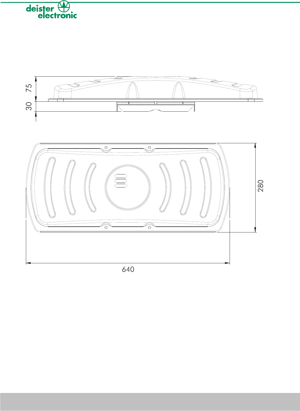
4. Mechanical dimensions
4.1 UDL500 housing
All dimensions in mm:
10 deister electronic GmbH 30890 Barsinghausen Germany V17/01/08
Wiring & Installation Instructions UDL500

5. Transmission protocol
The RS485 interface is being operated with 8 data bits, 1 stop bit and no parity bit. The
transmission rate can be adjusted to 9600, 19200, 38400 or 115200 baud.
The reader works with the “deBus” protocol. For details refer to document “UDL/UDK
deBus Protocol”.
6. Mounting
The back of the reader is prepared for mounting on masts and tubes. For mounting on
masts or ceilings,deister electronic provides the link holder LRM1 as an ideal supplement
(optional, art. nr. 6103.000).
6.1 Mast/Tube mounting
For mounting on masts/tubes the back of the reader is prepared in the way, that alignment
of the reader around its vertical or horizontal axis is possible. The jagged pipe guidings on
the back guarantee a safe tube mounting with a 360° justification round the tube and a
safe mounting of the reader as well.
V17/01/08 deister electronic GmbH 30890 Barsinghausen Germany 11
Wiring & Installation Instructions UDL500
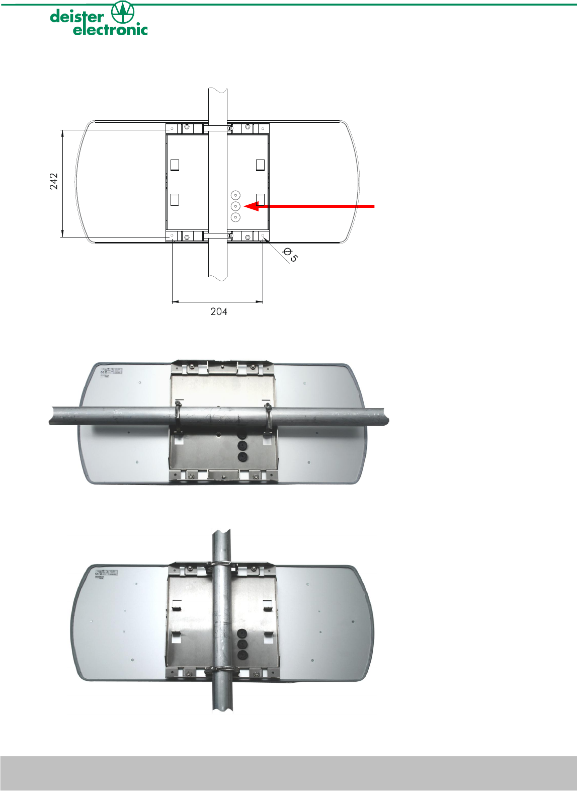
All dimensions in mm:
12 deister electronic GmbH 30890 Barsinghausen Germany V17/01/08
Wiring & Installation Instructions UDL500
cable outlets
mounting holes for wall mounting =
Ø 5mm
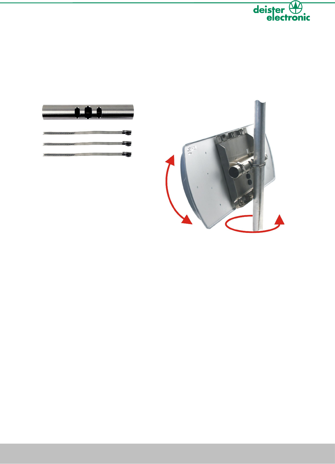
6.2 Extended mast holding device LRM2
(optional, art. nr. 6104.000)
For even more flexibility in mounting and alignment on the mast we recommend the use of
the extended mast holding device LRM2. This will give you the possibility to change the
angle of vertical inclination up to ±25°.
V17/01/08 deister electronic GmbH 30890 Barsinghausen Germany 13
Wiring & Installation Instructions UDL500
360°
± 25°
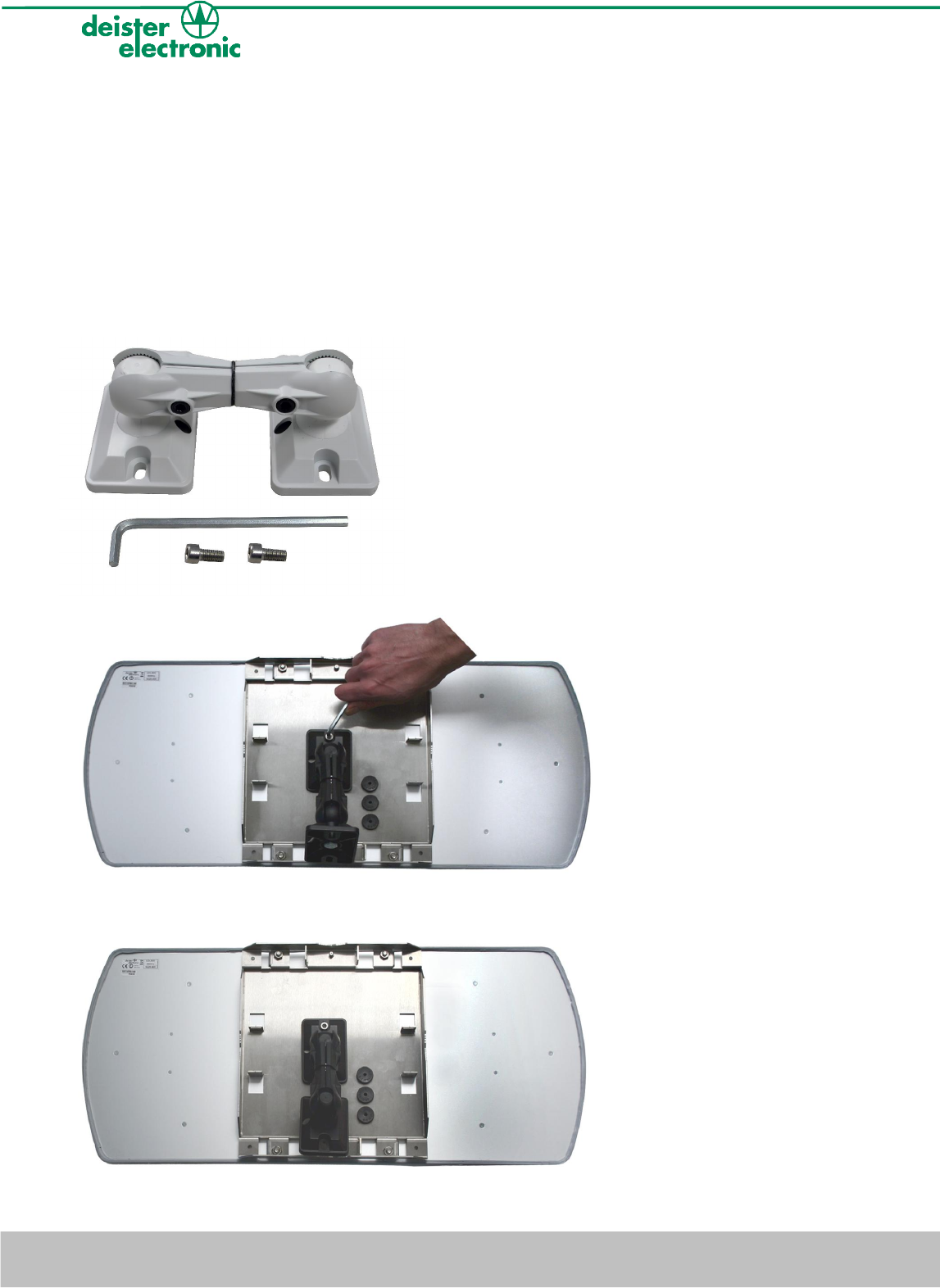
6.3 Wall mounting with link holder LRM1
For mounting on walls or ceilings the reader can be mounted directly or by help of the link
holder LRM1. With the LRM1 the reader can be positioned in many directions. Both
mounting plates of this device are connected ball-beared to a rotatable axis. Fixing the
correct position is carried out with a hexagon spanner.
6.4 Fixing link holder LRM1
(optional, art. nr. 6103.000)
14 deister electronic GmbH 30890 Barsinghausen Germany V17/01/08
Wiring & Installation Instructions UDL500

6.5 Function principle and environmental influences
The reader sends a high-frequent carrier signal. A transponder, which is located within the
area of this transmitted carrier, transmits this signal back with its own transponder data in a
modulated way. This very weak signal is being analyzed by the reader.
Because of the particular small-bandwidth and the high carrier frequency within MHz-
range this system is almost fail-safe. Nevertheless the range of the reader can be
negatively influenced. The following list shows what to pay attention to:
1. The reader must have visual contact to the transponder. There must not be any
walls or other devices between reader and transponder. Reading
through plastic film, card board, papers or glass windows may be possible in some
cases, but will reduce the reading range depending on the condition of the
material.
2. Water, ice and snow will absorb the carrier signal. Therefore the installer
should take care, that the front of the reader as well as the transponder can not be
covered with water, ice or snow.
3. If more than one reader will be installed, they may influence each other. To avoid
any problems, there can be fixed channels assigned to each single reader. It is
absolutely mandatory, that the readers operate on different
channels. The more the frequencies of the channels are apart, the less the
influence will be. In case the air interface EN 302 208 is being used, the reader
carries out a listen before talk (LBT) and chooses a free channel by its own.
4. Reflexions within the surrounding of the reader can influence the reading result in a
negative way. Therefore the reader should be mounted as free-standing as
possible. We strictly discourage from sunk-in installations.
V17/01/08 deister electronic GmbH 30890 Barsinghausen Germany 15
Wiring & Installation Instructions UDL500
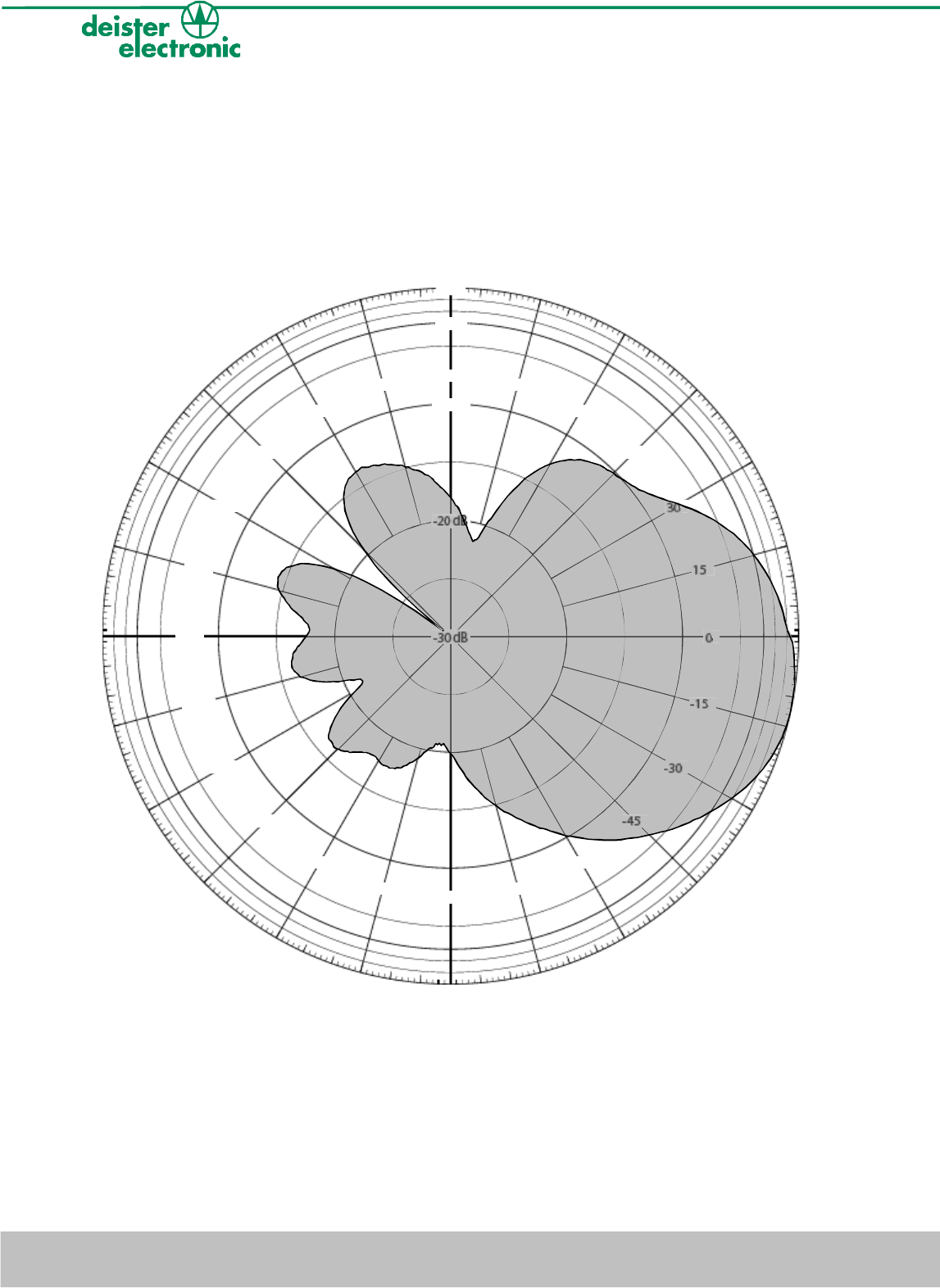
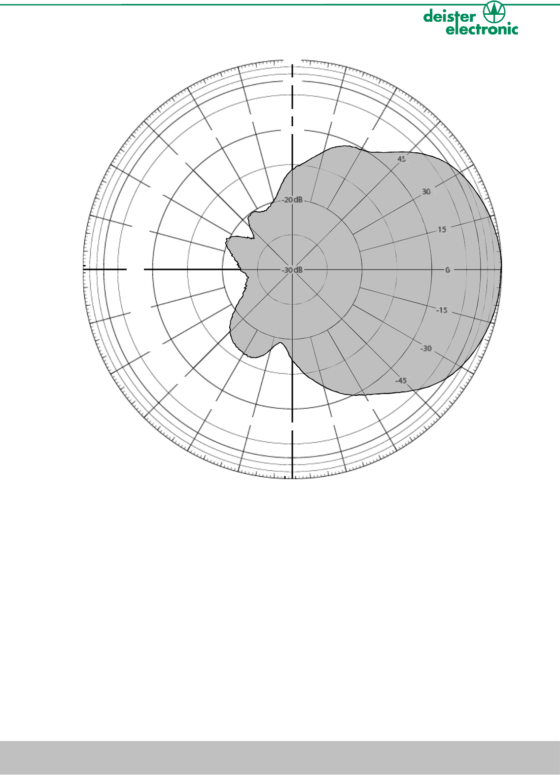
6.6 Radiation pattern of the transmitting antenna
Beamwidth horizontal: ≤70°
Beamwidth vertical: ≤70°
Gain: 4dBd
Polarization: circular (LHCP)
Pictured frequency: f = 866.8MHz
reader horizontal, polarization horizontal
16 deister electronic GmbH 30890 Barsinghausen Germany V17/01/08
Wiring & Installation Instructions UDL500
0d B
-3 dB
-10 dB
-20 dB
-30 dB
-165
-150
-135
-120
-105
-90
-75
-60
-45
-30
-15
0
15
30
45
60
75
90
105
120
135
150
165
180
30
-
-
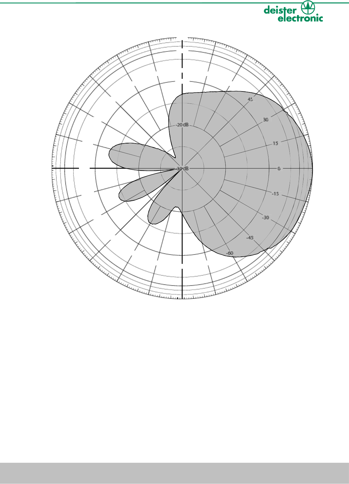
reader horizontal, polarization vertical
V17/01/08 deister electronic GmbH 30890 Barsinghausen Germany 17
Wiring & Installation Instructions UDL500
0d B
-3 dB
-10 dB
-20 dB
-30 dB
-165
-150
-135
-120
-105
-90
-75
-60
-45
-30
-15
0
15
30
45
60
75
90
105
120
135
150
165
180
20
-
-
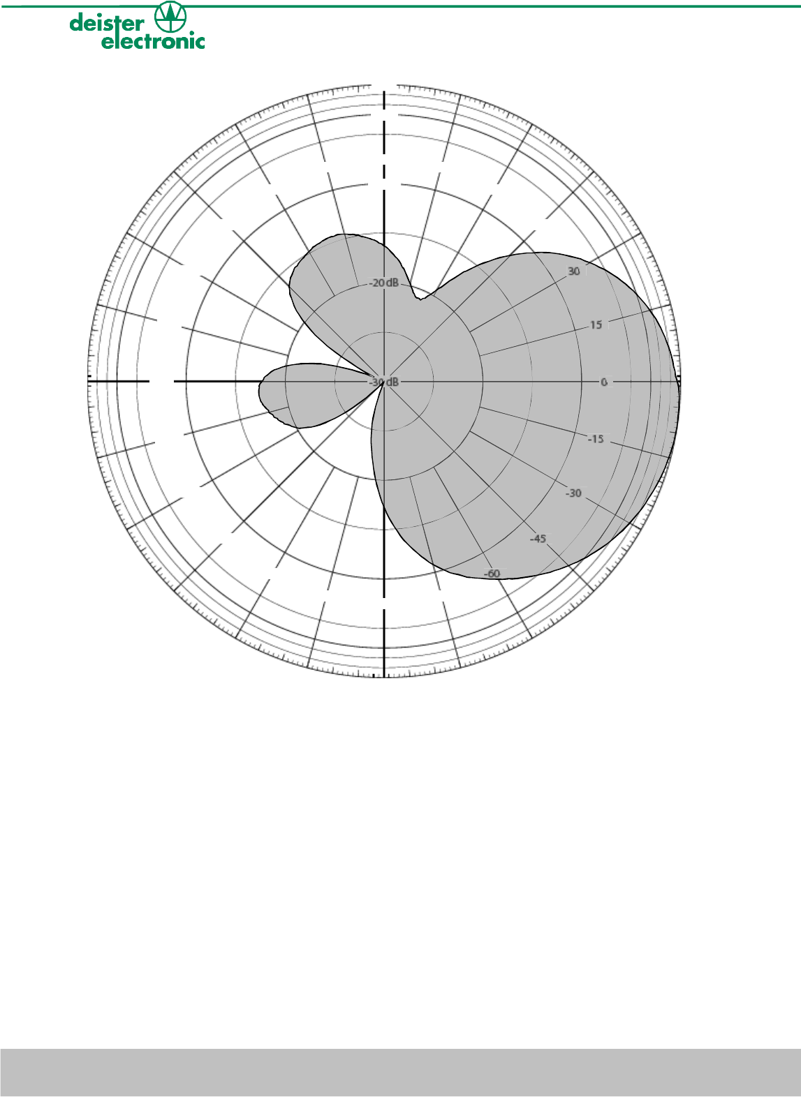
reader vertical, polarization horizontal
18 deister electronic GmbH 30890 Barsinghausen Germany V17/01/08
Wiring & Installation Instructions UDL500
0d B
-3 dB
-10 dB
-20 dB
-30 dB
-165
-150
-135
-120
-105
-90
-75
-60
-45
-30
-15
0
15
30
45
60
75
90
105
120
135
150
165
180
20
-
-
reader vertical, polarization vertical
V17/01/08 deister electronic GmbH 30890 Barsinghausen Germany 19
Wiring & Installation Instructions UDL500
0d B
-3 dB
-10 dB
-20 dB
-30 dB
-165
-150
-135
-120
-105
-90
-75
-60
-45
-30
-15
0
15
30
45
60
75
90
105
120
135
150
165
180
20
30
-
-
7. Configuration software
The configuration software “WebConfig” can be found on the CD delivered. It can be started
directly from the CD with no further installation.
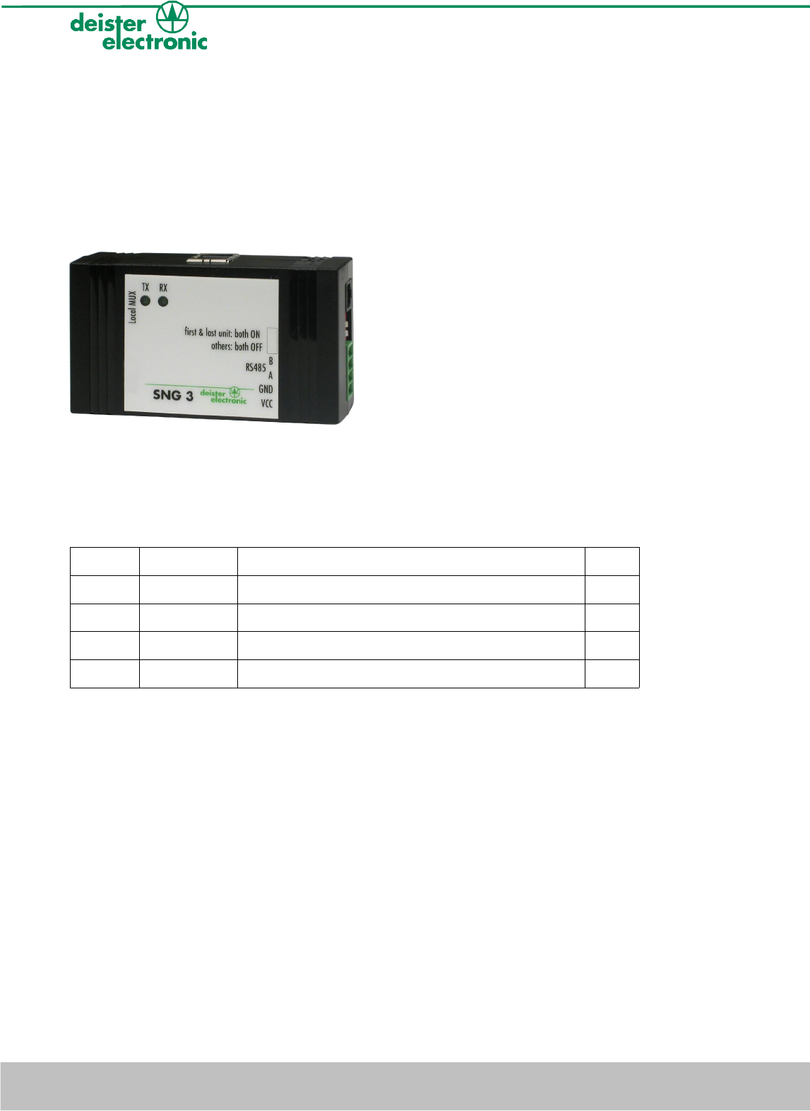
7.1 SNG3 interface converter
(optional, art.nr. 8782.000)
For connecting the reader to a host/PC via USB you can use the interface converter
SNG3. The driver needed is also to be found on the CD within delivery. In addition to that
the SNG3 powers the reader. For this a special wall power supply is available (optional,
art. nr. 8812.000).
UDL500 Name Function SNG3
Pin 3 +VCC voltage supply UDL500 (10 ... 30V/DC) Pin 1
Pin 2 GND ground Pin 2
Pin 9 RS 485 - A RS 485 interface, data line A Pin 3
Pin 10 RS 485 - B RS 485 interface, data line B Pin 4
Table 2: connection cable UDL500 to SNG3
20 deister electronic GmbH 30890 Barsinghausen Germany V17/01/08
Wiring & Installation Instructions UDL500
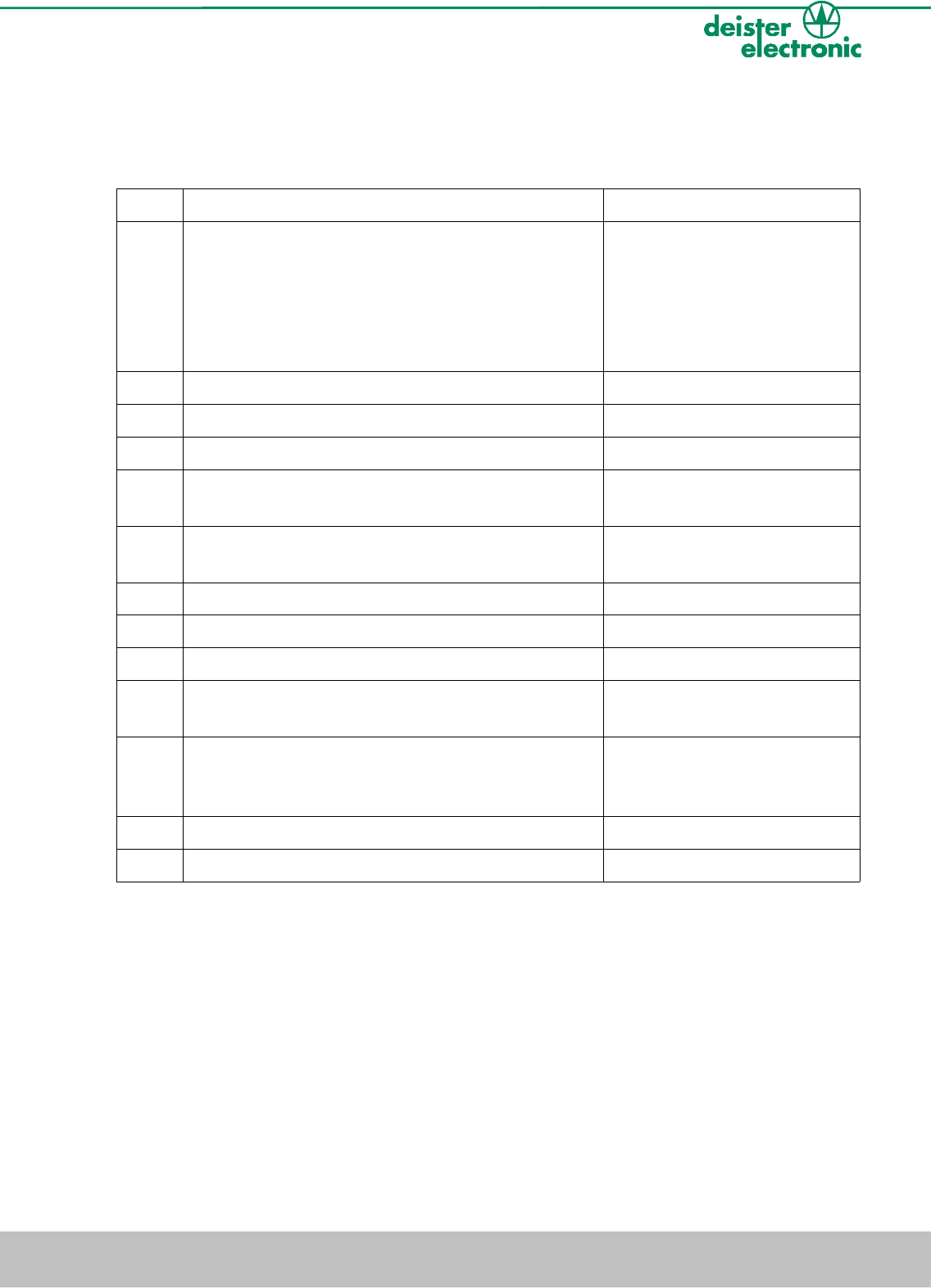
7.2 Configuration
Configuring the reader in combination with the SNG3 (optional) and the wall power
supply (optional) is carried out as follows:
Step Configuration Software “WebConfig” Reader UDL500
1 connecting reader to SNG3
(see table 2),
connecting SNG3 to PC via
USB-cable,
connecting wall power supply
to SNG3
2 starting configuration software “WebConfig”
3 select USB Serial Port
4 click on „Device“ – „Search addresses“
5 software searches for reader connected to
selected COM Port
6 after successful search the reader found will be
indicated
7 current reader configuration will be read
8 configuration menu will open
9 configuration can be modified by user
10 transfer the changed configuration to the reader
by click on “Apply Changes”
11 reader will store the new
configuration within its
internal non-volatile memory
12 end connection by click on “Offline”
13 program will be closed by „File“ - „Exit“
Table 3: configuration
V17/01/08 deister electronic GmbH 30890 Barsinghausen Germany 21
Wiring & Installation Instructions UDL500
7.3 Parameters
For a detailed description of the configuration parameters please refer to the document
“UDL/UDK deBus protocol”. Application notes regarding the configuration settings can be
found at “deister RFID Portal“ (www.deister.com – deister RFID Portal). If transponder type
EPC class1 gen2 is used, the configuration parameters refer to the specification of
EPCglobal™ (EPCglobal™, Class 1 Generation 2 UHF Air Interface Protocol Standard).
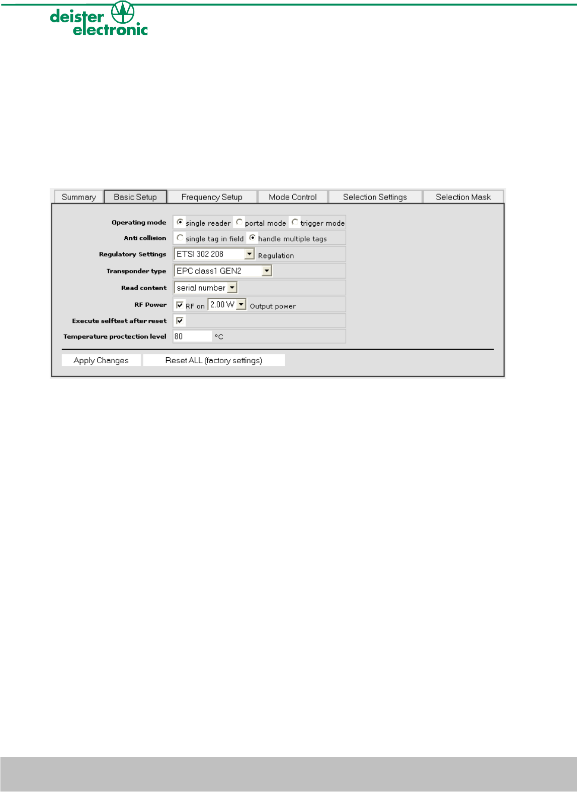
7.3.1 Basic Setup
Operating Mode
Single reader for operating of a single reading-/writing device
Portal mode for operating several reading-/writing devices using a data
concentration unit (DCU1)
Trigger mode for operating of a reading-/writing device using the trigger mode
Anticollision
single tag in field operation mode for reading transponder data, in case there is
only one tag in the field (anticollision deactivated)
handle multiple tags operation mode for reading transponder data, in case there is
more than one tag in the field (anticollision activated)
Regulatory Settings
Selection of the regulation used by reader ETSI 302 208 (EU)
ETSI 300 220 (EU), optional
FCC Part 15 (US), optional
Transponder Type
selection of transponder type, which has to be read/written
Read content
Serial number reading the EPC
Read mode for reading transponder data
Write mode for writing a transponder
22 deister electronic GmbH 30890 Barsinghausen Germany V17/01/08
Wiring & Installation Instructions UDL500

RF Power
RF switching field on/off
Output power output power of the reading/writing unit. The adjusted value indicates
the emitted power:
0.10W (ERP)
0.25W (ERP)
0.50W (ERP)
0.75W (ERP)
1.00W (ERP)
1.25W (ERP)
1.50W (ERP)
1.75W (ERP)
2.00W (ERP)
4.00W (EIRP, US)
Execute selftest after reset
executing a self test after reset
Temperature protection level
protection against overheating of the reading/writing device. In case of exceeding the
adjusted temperature the field will be switched off.
V17/01/08 deister electronic GmbH 30890 Barsinghausen Germany 23
Wiring & Installation Instructions UDL500
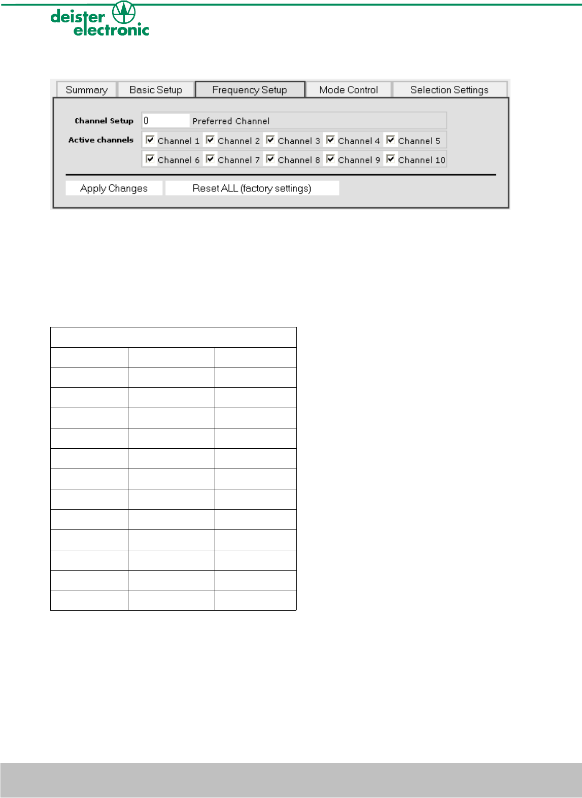
7.3.2 Frequency Setup
Channel Setup
the channel that will preferably be selected when switching the device on
Active channels
the channels that may be used by the reading/writing unit. This selection depends on the
particular regulatory chosen (see also Basic Setup).
ETSI 302 208 (EU)
Channel Nr. Frequency ERP
1 865.7MHz ≤ 2,00W
2 865.9MHz ≤ 2,00W
3 866.1MHz ≤ 2,00W
4 866.3MHz ≤ 2,00W
5 866.5MHz ≤ 2,00W
6 866.7MHz ≤ 2,00W
7 866.9MHz ≤ 2,00W
8 867.1MHz ≤ 2,00W
9 867.3MHz ≤ 2,00W
10 867.5MHz ≤ 2,00W
11 867.7MHz ≤ 500mW
12 867.9MHz ≤ 500mW
Table 4: ETSI 302 208 (EU)
24 deister electronic GmbH 30890 Barsinghausen Germany V17/01/08
Wiring & Installation Instructions UDL500
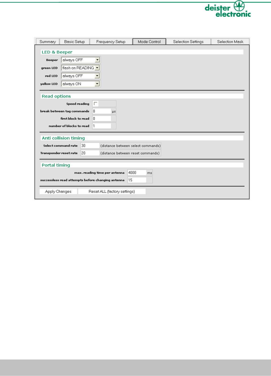
7.3.3 Mode Control
LED & Beeper
configuration beeper always OFF beeper off
indicate READING beeper sounds, while transponder is
being read
LEDs green, yellow, red always OFF LED off
flash on READING LED active, while transponder is being
read
always ON LED permanently active
V17/01/08 deister electronic GmbH 30890 Barsinghausen Germany 25
Wiring & Installation Instructions UDL500

Speed reading
increase of data rate between reader and transponder
Break between tag commands
break time between transponder command in 100µs steps
First block to read/write (only in reading-/writing mode)
first block (decimal), which has to be read/written
Number of blocks to read/write (only in reading-/writing mode)
number of blocks (decimal) which have to be read/written
Single Shot transmission (only with “single tag in field”, see 7.3.1)
idle time in 100ms steps between transmission of transponder data
Select command rate (only with “handle multiple tags”, see 7.3.1)
number of anticollision rounds after a select command has been sent
Transponder reset rate (only with “handle multiple tags”)
number of anticollision rounds after a reset command has been sent
Max. reading time per antenna (only in portal mode)
active time of the reader in portal mode
Successless read attempts before changing antenna (only in portal mode)
counter for anticollision rounds in which no tag has been read. After this, the reading
process will be aborted.
Interface mode (only in single reader mode or trigger mode)
report mode transponder data read will immediately be transmitted via RS485
interface
polling mode transponder data read will be stored within the reader memory and
will only be transmitted via RS485 interface after a poll command is
been received.
26 deister electronic GmbH 30890 Barsinghausen Germany V17/01/08
Wiring & Installation Instructions UDL500
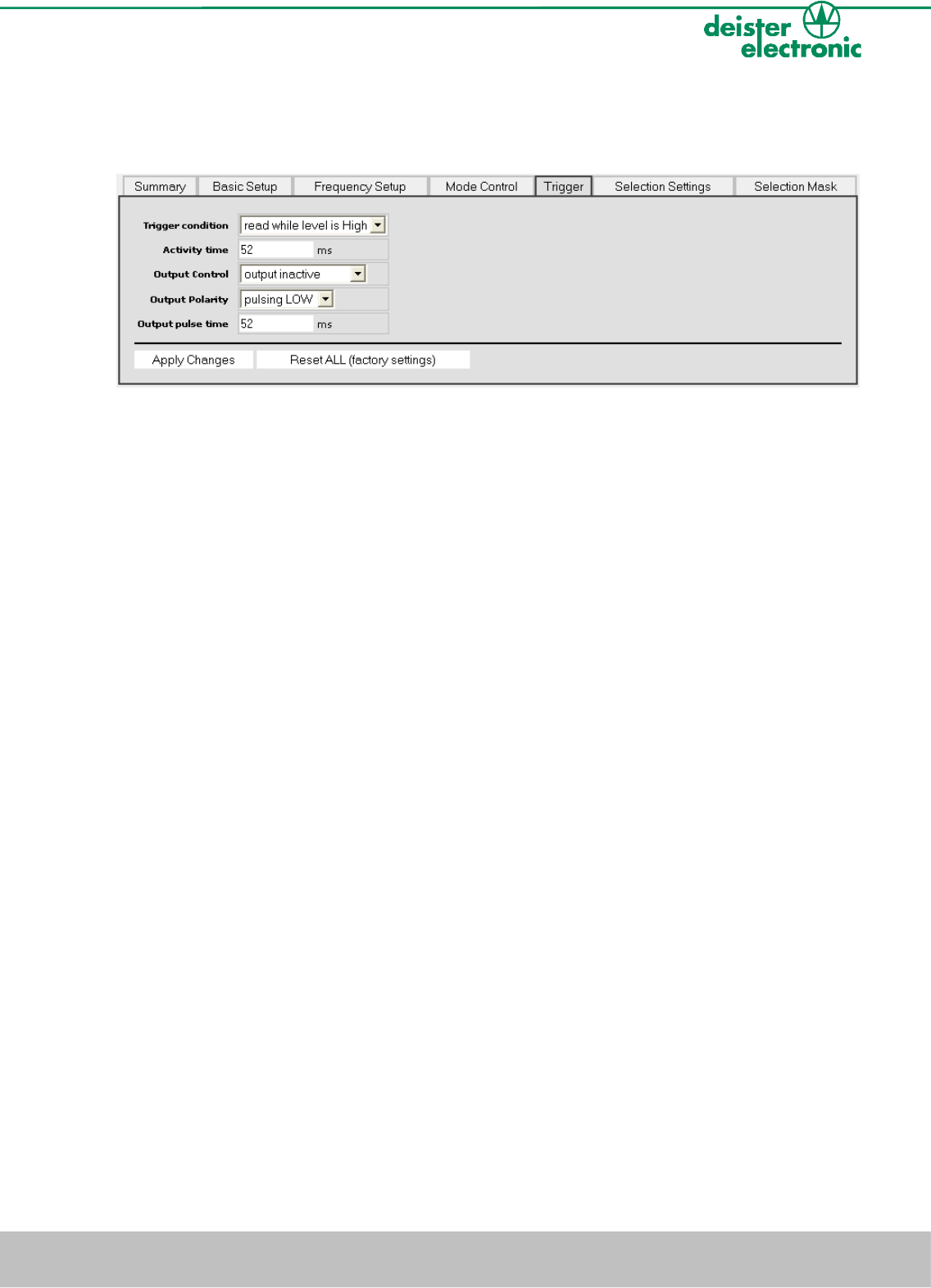
7.3.4 Trigger
The menu item “Trigger” is only available within the trigger mode (see also 7.3.1).
Trigger condition
configuration of the trigger condition:
read while level is high triggering to „high level“
read after rising edge triggering to rising edge
read after falling edge triggering to falling edge
anticollision trigger anticollision trigger: triggering ends, when no further
transponder can be read
Activity time
time in 6.5ms steps, while the field stays active after a trigger pulse
(only for edge controlled trigger conditions)
Output Control
configuration of output:
output inactive output switched off
pulse after READ switch output on after successful reading
pulse on NO READ switch output on after non successful reading
Output Polarity
configuration of output, when „pulse after READ“ or „pulse after NO READ“ have been set
in “Output Control”:
pulsing LOW setting output on „low“
pulsing HIGH setting output on „high“
Output pulse time
depending on the set output polarity, the digital output is set to ”low” or “high” for the
time set (6,5ms steps), if a trigger condition is met
V17/01/08 deister electronic GmbH 30890 Barsinghausen Germany 27
Wiring & Installation Instructions UDL500
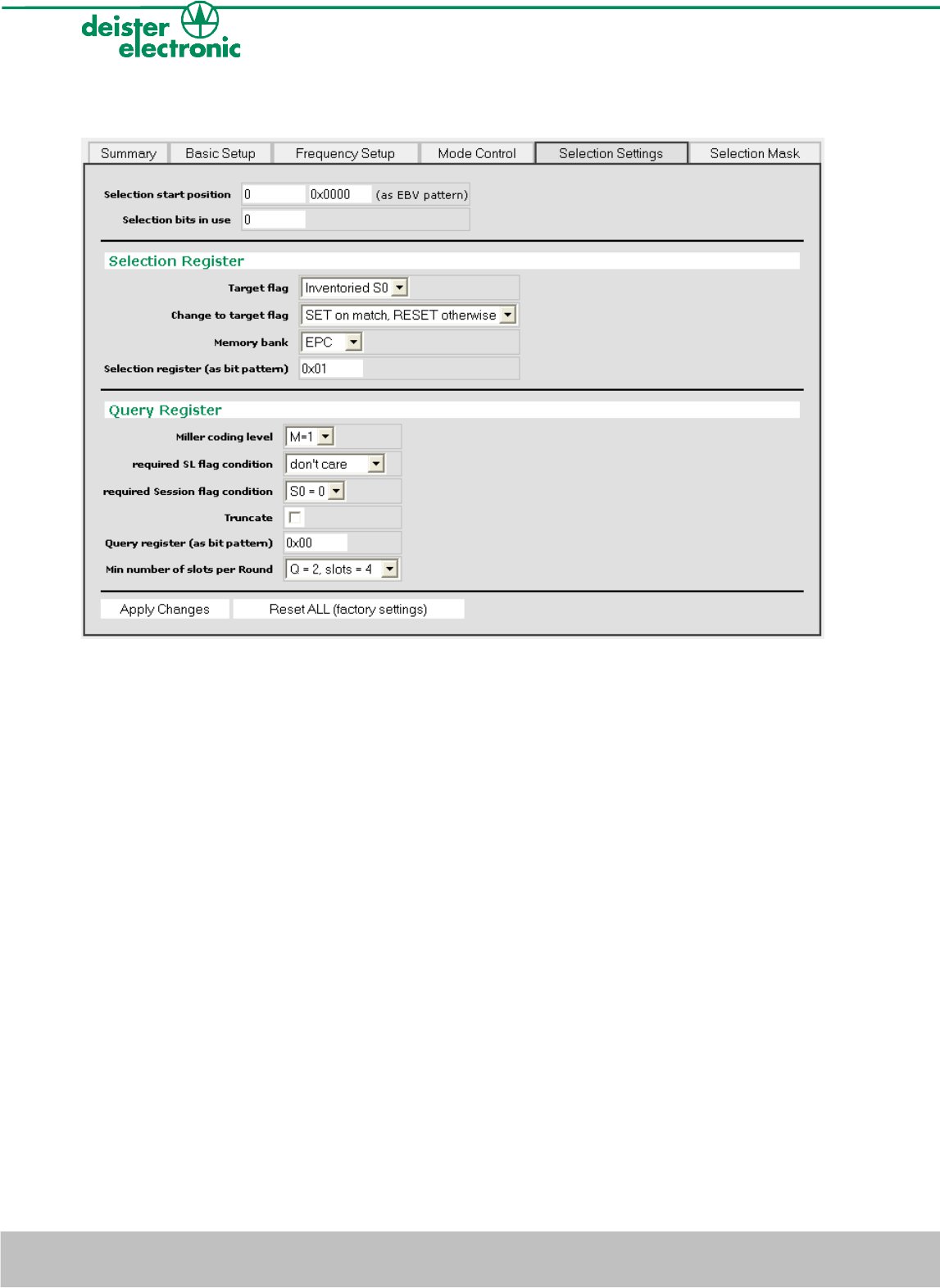
7.3.5 Selection Settings
Selection start position
address (decimal) of the selected memory bank the selection is started at
Selection bits in use
number (decimal) of bits to be compared within selection
Target flag
used flag for the selection process
Change to target flag
change to target flag, in case selection matches
Memory bank
memory bank the selection is carried out at
Selection register (as bit pattern)
deBus selection register byte (hexadecimal)
Miller coding level
setting of the Miller coding level used
Required SL flag condition
required SL flag condition to let these tags participate in the anticollision round
28 deister electronic GmbH 30890 Barsinghausen Germany V17/01/08
Wiring & Installation Instructions UDL500
Required Session flag condition
required Session flag condition to let these tags participate in the anticollision round
Truncate
activating the truncate function to use a shorter reply from the tag
Query register (as bit pattern)
deBus query register byte (hexadecimal)
Min number of slots per Round
minimum number of slots per anticollision round
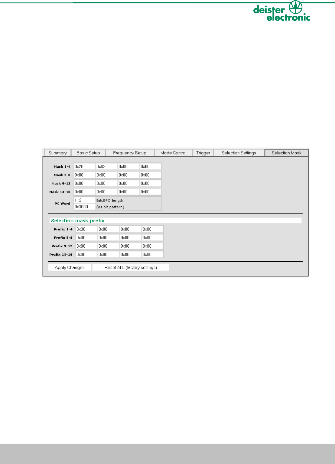
7.3.6 Selection Mask
Selection Mask
selection mask divided into separate bytes (hexadecimal)
PC Word (only with “Truncate”)
length of PC + EPC bits (decimal) and PC bits as bit pattern (hexadecimal)
Selection Mask Prefix (only with “Truncate”)
prefix mask for truncate function
V17/01/08 deister electronic GmbH 30890 Barsinghausen Germany 29
Wiring & Installation Instructions UDL500
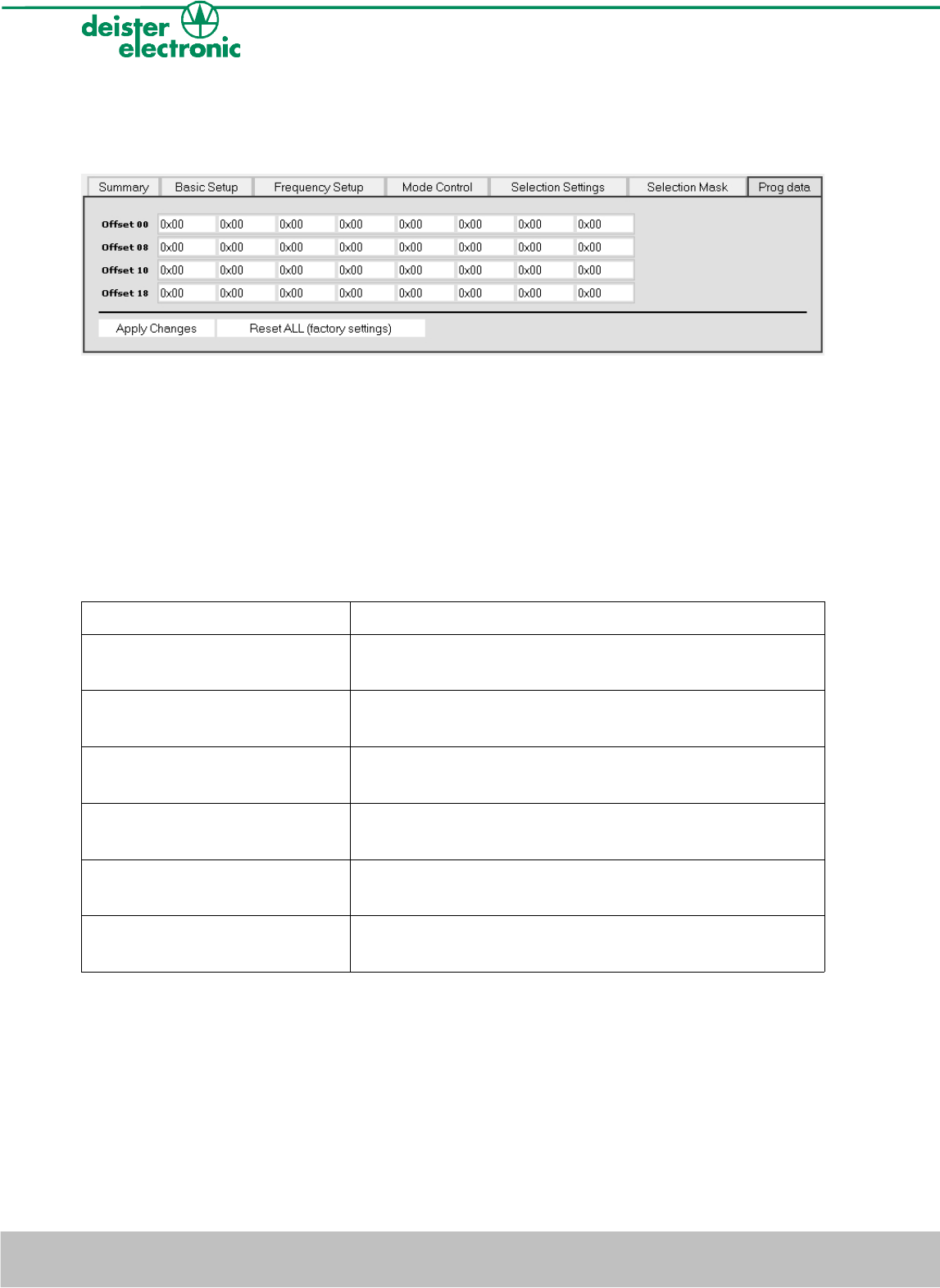
7.3.7 Prog data
The menu item „Prog data“ is only available within writing mode (see 7.3.1).
Input mask for hexadecimal data to be written into transponder memory. Division into
separate bytes, writing takes place from Offset 00.
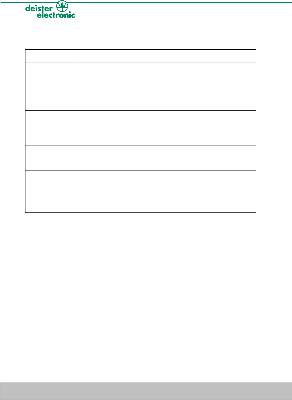
7.4 LEDs and Beeper
The reader has three LEDs and one beeper in order to indicate the reader status. The
following table refers to the standard settings.
LEDs Status UDL500
yellow: on
red and green: off
reader is ready to operate, field is switched on
reader is ready to read/write transponder
yellow and red: on
green: off
reader is ready to operate, field is switched off
yellow and green: an
red: off
reader is ready to operate, communication between
reader and tag (reading/writing)
green and red: an
yellow: off
reader carries out a reset, field is switched off
reader is not ready to operate
yellow: blinking
red and green: off
supply voltage too low
red: blinking and beeper sound
green and yellow: off
malfunction
table 5: reader status indication UDL500
30 deister electronic GmbH 30890 Barsinghausen Germany V17/01/08
Wiring & Installation Instructions UDL500
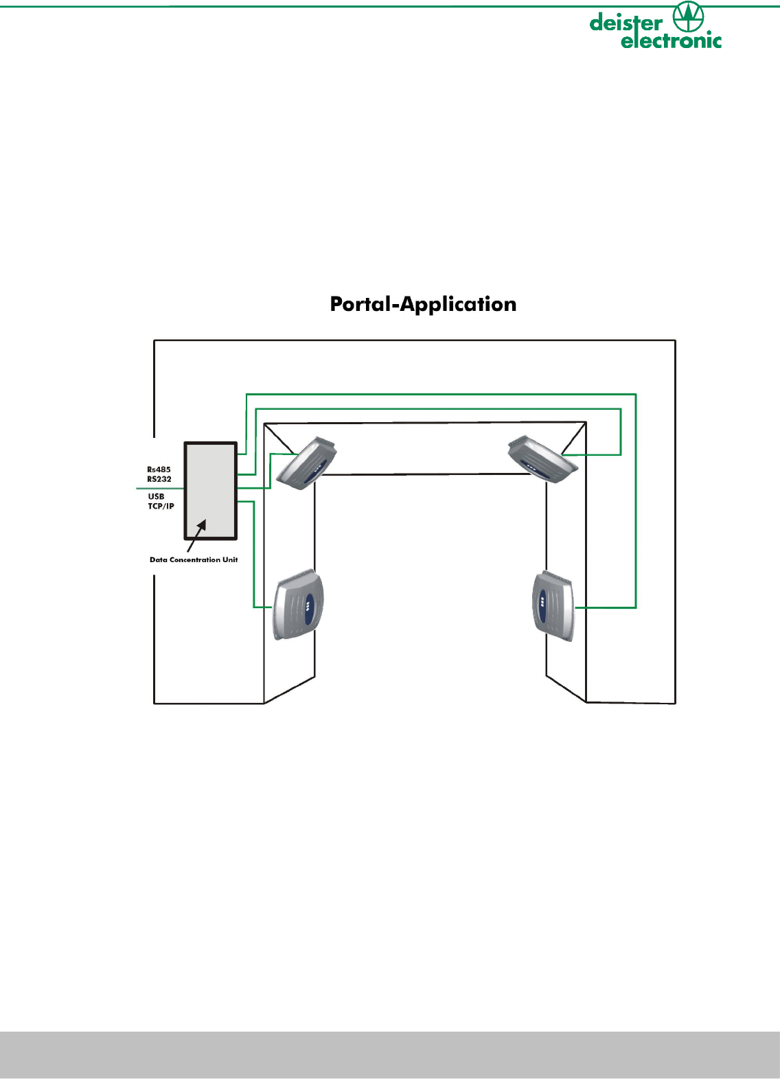
8. Portal application with DCU1 Data Control Unit
(optional, art. nr. 9240.100)
In order to realize portal/gate solutions, up to four UDL500 can be connected to the
DCU1 Data Control Unit via RS485 interface. The readers have to be connected radially
to the DCU1 using 4-core cables (4 x 0.5mm).
The DCU1 manages and controls all the readers, while each reader can be configured
separately. In case of multiple reading of transponder data, the data can be filtered first
and will then be transmitted to the host system.
Portal/Gate application with UDL500 readers
For a detailed description of the portal installation please refer to the document
„Application Note UHF Portal“.
V17/01/08 deister electronic GmbH 30890 Barsinghausen Germany 31
Wiring & Installation Instructions UDL500
9. Accessories of the UHF product family
Article Description Article number
LRM1 Link holder 6103.000
LRM2 Extended link holder 6104.000
Mounting plate Mounting plate for UDL500 9292.000
AC/DC Adapter
Euro
Wall power supply, input voltage 230V/AC, output
voltage 12V/DC (1A), Friwo® plug
8812.000
AC/DC Adapter
International
Wall power supply, input voltage 100-240V/AC,
output voltage 12V/DC (1.25A), Friwo® plug
6757.000
AC/DC Power
Supply
AC/DC rail power supply, input voltage
100-260V/AC, output voltage 24V/DC (2.5A)
6756.000
SNG3 Smart
Network
Gateway
Interface converter USB/RS485, incl. USB cable and
driver software
8782.000
MOXA Adapter Interface converter Ethernet/RS485/RS232, incl. wall
power supply and driver software
8783.000
DCU1 Data Control Unit for operation with up to four
UDL500 readers, interfaces: RS232, RS485, Ethernet,
4 trigger inputs, 4 switch outputs, rail mounting
9240.100
32 deister electronic GmbH 30890 Barsinghausen Germany V17/01/08
Wiring & Installation Instructions UDL500

10. Regulatory Notices
10.1 Europe
Hereby, deister electronic GmbH declares, that this equipment - if used according to the
instructions - is in compliance with the essential requirements and other relevant provisions
of the RTTE Directive 1999/5/EG.
A full declaration of conformity can be requested at:
info@deister-gmbh.de
Approved for use in the following European countries:
A, B, BUL, CH, CYP, CZ, D, DK, E, EST, F, FIN, GB, GR, H, HNG, ICE, IRL, LIE,
LTU, LUX, LVA, MA, N, NLP, PL, ROU, S, SK, SVN
10.2 FCC Digital Device Limitations
Radio and Television Interference
This equipment has been tested and found to comply with the limits for a Class A digital
device, pursuant to Part 15 of the FCC rules. These limits are designed to provide
reasonable protection against harmful interference when the equipment is operated in a
commercial environment. This equipment generates, uses and can radiate radio frequency
energy and, if not installed and used in accordance with the instruction manual, may
cause harmful interference to radio communications. Operation of this equipment in a
residential area is likely to cause harmful interference, in which case the user will be
required to correct the interference at his own expense.
This device complies with Part 15 of the FCC rules. Operation is subject to the following
two conditions: (1) This device may not cause harmful interference, and (2) this device
must accept any interference received, including interference that may cause undesired
operation.
In order to maintain compliance with FCC regulations, shielded cables must be used with
this equipment. Operation with non-approved equipment or unshielded cables is likely to
result in interference to radio and television reception.
Caution! Changes or modifications not expressly approved by the manufacturer could void
the user´s authority to operate this equipment.
V17/01/08 deister electronic GmbH 30890 Barsinghausen Germany 33
Wiring & Installation Instructions UDL500

10.3 FCC Notice
To comply with FCC part 15 rules in the United States, the system must be professionally
installed to ensure compliance with the Part 15 certification. It is the responsibility of the
operator and professional installer to ensure that only certified systems are deployed in the
United States. The use of the system in any other combination (such as co-located
antennas transmitting the same information) is expressly forbidden.
10.4 FCC Radiation Exposure Statement
This equipment complies with the FCC radiation exposure limits set forth for an
uncontrolled environment. This equipment should be installed and operated with minimum
distance of 20 cm between the radiator and the human body.
10.5 Industry Canada
This Class A digital apparatus complies with Canadian ICES-003.
Cet appareil numérique de la classe A est conforme à la norme NMB-003 du Canada.
34 deister electronic GmbH 30890 Barsinghausen Germany V17/01/08
Wiring & Installation Instructions UDL500

Notes:
V17/01/08 deister electronic GmbH 30890 Barsinghausen Germany 35
Wiring & Installation Instructions UDL500

Germany:
deister electronic GmbH
Hermann-Bahlsen Str. 11
30890 Barsinghausen
Tel.: +49 (0) 51 05 - 51 61 11
Fax: +49 (0) 51 05 - 51 62 17
info@deister-gmbh.de
www.deister.com
Great Britain:
deister electronic (UK) Ltd.
Stapleton Way, Enterprise Park
Spalding, Lincolnshire PE11 3YQ
Tel.: +44 (0) 1775 - 717100
Fax: +44 (0) 1775 - 717101
info@deister.co.uk
USA:
deister electronic USA Inc.
9303 Grant Avenue
Manassas, VA 20110
Tel.: +1 703 - 368 2739
Fax: +1 703 - 368 9791
info@deister.com
Canada:
deister electronic Inc.
1099 Kingston Road, Suite 212
Pickering, ON L1V 1B5
Tel.: +1 905 - 837 5666
Fax: +1 905 - 837 0777
info@deister-electronic.com
Japan:
deister electronic Japan, LTD.
Toshiba Hoshikawa Bldg. 4F
2-4 Kawabe-chô
Hodogaya-ku, Yokohama-shi
Kanagawa, 240-0001
Tel.: +81 50 5534 5167
Fax: +81 90 4425 1153
info@deister.jp
deister worldwide
Belgium & Luxemburg:
deister electronic office
Business Park E 19
Battelsesteenweg 455/A
2800 Mechelen
Tel.: +32 (0) 15 - 28 09 68
Fax: +32 (0) 15 - 28 09 71
info@benelux.deister.com
The Netherlands:
deister electronic office
Tolnasingel 3
2411 PV Bodegraven
Tel.: +31 (0) 1726 - 32970
Fax: +31 (0) 1726 - 32971
info@nl.deister.com
France:
deister electronic france
101 rue Pierre Semard
92320 Chatillon
Tel.: +33 (0) 1 47 - 35 78 78
Fax: +33 (0) 1 47 - 35 92 59
info@deister.fr