Dekolink Wireless DCSB40D95AC Multi Channel RF Signal Booster User Manual 1
Dekolink Wireless Ltd Multi Channel RF Signal Booster 1
Contents
- 1. User Manual 1
- 2. User Manual 2
User Manual 1
© Dekolink Wireless Ltd.—All Rights Reserved
Rev. 1.3

ABOUT THIS MANUAL
This Product Manual describes the Deko4078SD Digital Multi Channel Selective
700/800 MHz signal booster and provides information on the setup, configuration
and troubleshooting procedures.
TO WHOM IT IS INTENDED
This Product Manual is intended for experienced technicians and engineers. It is
assumed that the customers installing, operating, and maintaining Deko4078SD
signal boosters are familiar with the basic functionality of signal boosters.
NOTICE Confidential - Authorized Customer Use
This document may be used in its complete form only and is solely for the use of
Dekolink Wireless Ltd. employees and authorized Dekolink Wireless channels or
customers. The material herein is proprietary to Dekolink Wireless Ltd. Any
unauthorized reproduction, use or disclosure of any part thereof is strictly prohibited.
All trademarks and registered trademarks are the property of their respective
owners.
DISCLAIMER OF LIABILITY
The remedies provided herein are the Buyer’s sole and exclusive remedies. Dekolink
Wireless Ltd. shall not be viable for any direct, incidental, or consequential damages,
whether based on contract, tort, or any legal theory.
Dekolink Wireless
International Headquarters
16 Bazel St., Kiryat-Arieh,
Petah-Tikvah 49001
ISRAEL
Tel.: +972 3 918-0180
Fax: +972 3 918-0190
E-mail: marketing@dekolink.com
Website: www.dekolink.com
Dekolink USA, Inc.
Americas Group
550 Club Drive
Suite. 470
Montgomery, Texas 77316-3094, USA
Tel: +1-936-582-7100
Fax: +1- 936-582-7108
E-mail: marketing@dekolinkusa.com
Website: www.dekolink.com
© Dekolink Wireless Ltd
P/N 300SC30031 Rev. 1.2
PRODUCT MANUAL DEKO4078SD MULTI-CHANNEL SIGNAL BOOSTER DEKOLINK WIRELESS LTD.
P/N 300SC30031 Rev. 1.2 Proprietary Data Page 3
SAFETY WARNINGS
Throughout this manual, important safety warnings are included to warn of possible
hazards to persons or equipment. A safety warning identifies a possible hazard and
then describes what may happen if the hazard is not avoided. The safety warnings –
in the form of Dangers, Warnings and Cautions must be followed at all times. These
warnings are flagged by the use of a warning icon, usually the triangular alert icon
seen below. The exclamation point within the triangular alert icon is intended to warn
the operator or service personnel of operation and maintenance from factors related
to the product and its operating environment, which could pose a safety hazard.
GENERAL SAFETY WARNINGS CONCERNING USE OF THIS SYSTEM
Always observe standard safety precautions during installation, operation and
maintenance of this product. Only a qualified and authorized personnel should carry
out adjustment, maintenance or repairs to the components of this equipment.
DANGER: ELECTRICAL SHOCK
This equipment is intended to be installed indoor. Wet conditions increase the
potential for receiving an electric shock when installing or using electrically powered
equipment. To prevent electrical shock when installing or modifying the system
power wiring, disconnect the wiring at the power source before working with
un-insulated wires or terminals.
CAUTION: RF EXPOSURE
To satisfy FCC RF exposure requirements for mobile transmitting devices, a separation
distance of 100 cm or more should be maintained between the antenna of this device
and persons during device operation.
To ensure compliance, operations at closer than this distance is not recommended. The
antenna used for this transmitter must not be co-located in conjunction with any other
antenna or transmitter.
WARNING: RESTRICTED ACCESS LOCATION
Access to the Dekolink 700/800 DMSB signal booster installation location is restricted
to SERVICE PERSONNEL and to USERS who have been instructed on the restrictions
and the required precautions to be taken.
ATTENTION: SYSTEM TESTING
All system tests should be performed with FM signals.
PRODUCT MANUAL DEKO4078SD MULTI-CHANNEL SIGNAL BOOSTER DEKOLINK WIRELESS LTD.
Page 4 Proprietary Data P/N 300SC30031 Rev. 1.2
Glossary
The following is a list of abbreviations and terms used throughout this document.
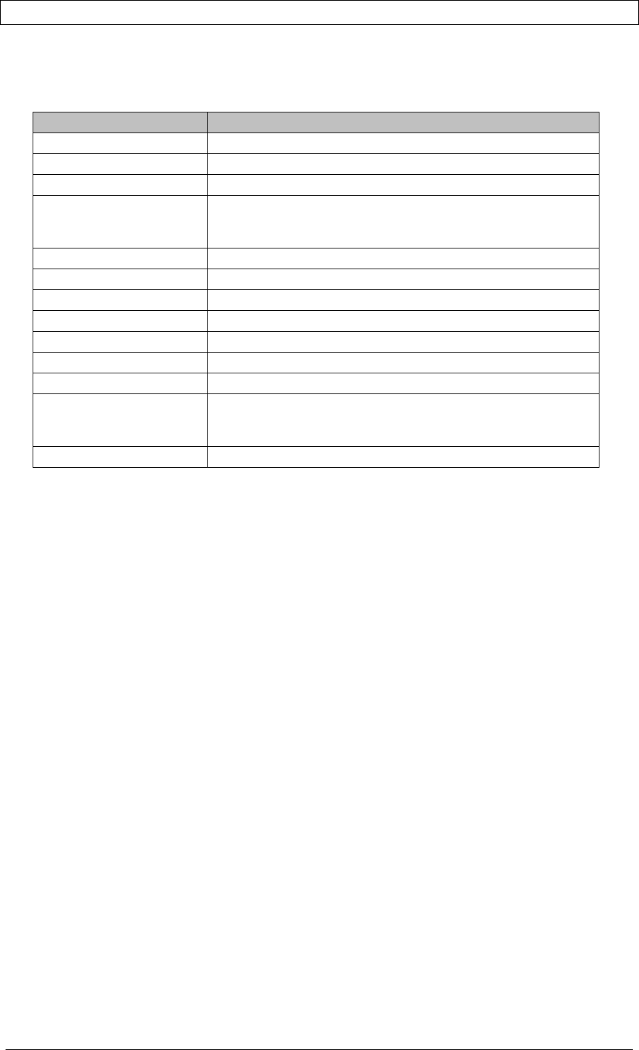
Abbreviation/Term Definition
AGC Automatic Gain Control
DMSB Digital Multi Channel Signal Booster
DDF Dekolink Digital Filter
DL Downlink - The path covered from the Base Transceiver
Station (BTS) to the subscribers/service area via the 700/800
DMSB UHF
DSP Digital Signal Processing
ESD Electro-Static Discharge
FPGA Field Programmable Gate Array
IF Intermediate Frequency
PLL Phased Locked Loop
RF Radio Frequency
MT 700/800 DMSB signal booster Management Tool
UL Uplink - The path covered from the subscribers/service area
to the Base Transceiver Station (BTS) via the 700/800
DMSB UHF
VSWR Voltage Standing Wave Ratio

PRODUCT MANUAL DEKO4078SD MULTI-CHANNEL SIGNAL BOOSTER DEKOLINK WIRELESS LTD.
P/N 300SC30031 Rev. 1.2 Proprietary Data Page 5
REVISION HISTORY
The revision history for this document is shown in Table 1-1.
Table
1-1: Revision history
P/N Revision Date Description
300SC30031 1.0 14-July-2008 Initial Version
300SC30031 1.2 11-AUG-08 Modifying model numbers

PRODUCT MANUAL DEKO4078SD MULTI-CHANNEL SIGNAL BOOSTER DEKOLINK WIRELESS LTD.
Page 6 Proprietary Data P/N 300SC30031 Rev. 1.2
CONTENTS
About This Manual ....................................................................................................................... 2
To Whom It Is Intended ............................................................................................................... 2
Notice ............................................................................................................................................ 2
Disclaimer of Liability .................................................................................................................. 2
Safety Warnings ........................................................................................................................... 3
General Safety Warnings Concerning Use of This System ..................................................... 3
Glossary ........................................................................................................................................ 4
Revision History ........................................................................................................................... 5
1 INTRODUCTION ...................................................................................................................... 9
1.1 Features ........................................................................................................................... 9
1.2 Models ............................................................................................................................ 10
1.3 Architecture ................................................................................................................... 10
1.4 DMSB System Elements ............................................................................................... 11
1.4.1 Main Unit ....................................................................................................... 12
1.4.2 Power Amplifier Unit ...................................................................................... 13
1.4.3 Power Supply Interfaces ............................................................................... 15
2 Site and Installation Requirements..................................................................................... 16
2.1 Rack Installation, Environment and Cables ............................................................... 16
2.2 Antenna Requirements ................................................................................................. 16
2.2.1 Base (Donor) Antenna .................................................................................. 16
2.2.2 Mobile (Service) Antenna .............................................................................. 16
2.3 Grounding Wires Requirements .................................................................................. 17
2.4 RF Cable Installation Guidelines ................................................................................. 17
3 Physical Installation ............................................................................................................. 18
3.1 Overview ........................................................................................................................ 18
3.2 Unpacking ...................................................................................................................... 18
3.3 Connecting the Donor and Service Antennas ............................................................ 19
3.4 Verifying Ground Connections .................................................................................... 20
3.5 Power Up ........................................................................................................................ 20
4 Commissioning the System ................................................................................................ 21
4.1 Opening a Session ........................................................................................................ 21
4.1.1 Connecting the Signal Booster to the Computer........................................... 21
4.1.2 Configure the Computer Network Parameters .............................................. 21
4.1.3 Login to the Signal Booster ........................................................................... 22
4.2 Commissioning the System ......................................................................................... 23
4.2.1 Configuring the Booster Parameters ............................................................. 23
4.2.2 Viewing Alarms ............................................................................................. 25

PRODUCT MANUAL DEKO4078SD MULTI-CHANNEL SIGNAL BOOSTER DEKOLINK WIRELESS LTD.
P/N 300SC30031 Rev. 1.2 Proprietary Data Page 7
4.2.3 Configuring the Filters ................................................................................... 26
4.2.4 Configuring the Modem Parameters ............................................................. 28
4.3 Verifying Site Coverage ................................................................................................ 29
5 Navigating the 700/800 DMSB signal booster Management Tool .................................... 30
5.1 Access Levels ............................................................................................................... 30
5.2 Main Window ................................................................................................................. 30
5.3 Settings .......................................................................................................................... 30
5.3.1 General.......................................................................................................... 30
5.3.2 Advanced – Installation ................................................................................. 32
5.3.3 Filters ............................................................................................................. 34
5.4 Alarms ............................................................................................................................ 37
5.4.1 Summary View .............................................................................................. 37
5.4.2 Logs ............................................................................................................... 38
5.5 Measurements ............................................................................................................... 38
5.6 Administration ............................................................................................................... 39
6 DMSB MT Operations ........................................................................................................... 40
6.1 Filters .............................................................................................................................. 40
6.1.1 Adding a Filter ............................................................................................... 40
6.1.2 Editing Filters ................................................................................................ 41
6.1.3 Deleting Filters .............................................................................................. 42
6.2 Generating ID Tone on Channels ................................................................................ 42
6.3 Modifying DMSB Booster Parameters ........................................................................ 44
6.4 Viewing Online Booster Parameters ........................................................................... 44
6.5 Monitoring Alarms ........................................................................................................ 45
6.5.1 System Alarms and External Alarms ............................................................ 45
6.5.2 Specific Channel Alarms ............................................................................... 47
6.6 Viewing Graphic Display of Filter ................................................................................ 48
6.7 Defining the External Alarms ....................................................................................... 48
6.8 Sliding Window Configuration ..................................................................................... 50
6.9 Viewing System Information ........................................................................................ 50
7 Administration ...................................................................................................................... 52
7.1 Managing Users ............................................................................................................ 52
7.1.1 User Levels ................................................................................................... 52
7.1.2 Viewing the List of Defined Users ................................................................. 52
7.1.3 Adding Users ................................................................................................. 53
7.1.4 Editing Users ................................................................................................. 53
7.1.5 Deleting a User ............................................................................................. 53
7.2 Configuration, Backup and Restore ............................................................................ 54
7.2.1 The Configuration Backup Window ............................................................... 54
7.2.2 SW Upgrade .................................................................................................. 54
7.2.3 Configuration Backup and Restore ............................................................... 56
7.2.4 Uploading New Filters ................................................................................... 58
Appendix A: RF Connections ................................................................................................... 59
Appendix B: Specifications (@+25°C) ..................................................................................... 60

PRODUCT MANUAL DEKO4078SD MULTI-CHANNEL SIGNAL BOOSTER DEKOLINK WIRELESS LTD.
Page 8 Proprietary Data P/N 300SC30031 Rev. 1.2
Appendix C: Configuration and Management Using DDF Application ................................ 61
Commissioning the Signal Booster .................................................................................... 61
Installing the DMSB Management Tool on the Computer ......................................... 61
Opening a Session .................................................................................................... 62
Configuring the Booster Parameters ......................................................................... 63
Configuring the Channels .......................................................................................... 64
Navigating the Signal Booster Management Tool ............................................................. 66
Access Levels ............................................................................................................ 66
Main Window ............................................................................................................. 66
DMSB MT Operations ........................................................................................................... 71
Frequency Shift ......................................................................................................... 71
Viewing Graphic Display of Filter .............................................................................. 72
FPGA Route .............................................................................................................. 73
Viewing Online DMSB signal booster Parameters .................................................... 74
Saving / Loading Configurations ............................................................................... 74
Appendix D: Muting Power Amplifiers and Performing output Attenuation Proceudres .. 75
Opening a Session ............................................................................................................... 75
Muting a Power Amplifier .................................................................................................... 76
Output Attenuation ............................................................................................................... 77
Appendix E: Dekolink Wireless Limited Warranty ................................................................. 78
PRODUCT MANUAL DEKO4078SD MULTI-CHANNEL SIGNAL BOOSTER DEKOLINK WIRELESS LTD.
P/N 300SC30031 Rev. 1.2 Proprietary Data Page 9
1 INTRODUCTION
Deko4078SD Digital Multi-Channel Signal Booster provides cost effective indoor and
outdoor communications coverage for the complete 700/800MHz Public Safety
spectrum assigned to the wireless networks.
Deko4078SD meets public safety infrastructure design requirements that include
higher base station site elevation, higher power output per channel, transmission
only on traffic channels that are in use and single receiver omni-directional site.
The system supports advanced Digital Signal Processing (DSP) technology,
programmable digital filters - where each filter supports up to 24 channels, and
programmable bandwidth of up to 12 MHz. These capabilities enable the user to
quickly and simply customize the Booster according to changing site requirements.
A SmartALC power control algorithm automatically optimizes the gain setting by
learning the actual range of RSSI levels over a user-specified period of time. The
SmartALC algorithm prevents oscillations, reduces the amount of isolation required
by the system and optimizes the system to minimize noise rise at the donor cell site.
An intuitive GUI based Management Tool (RMT) provided with the Booster is used to
configure, monitor and manage the Booster through an Ethernet connection to the
system.
Figure 1. Deko4078SD
1.1 FEATURES
• 95 dB RF gain
• Composite Output Power:
• Downlink: + 40 dBm
• Uplink: + 27 dBm
• Up to 24 channels per system with software defined channel frequency
• Software defined filter bank supporting up to 100 filters
• Filter bandwidth selection of 12.5KHz to 4.5 MHz

PRODUCT MANUAL DEKO4078SD MULTI-CHANNEL SIGNAL BOOSTER DEKOLINK WIRELESS LTD.
Page 10 Proprietary Data P/N 300SC30031 Rev. 1.2
• AGC per channels/band
• Dry-contact alarms
• High linear amplification
• High spectral purity
• Highly accurate frequency selection
• Excellent out-of-band interference prevention
• Mechanism for tunable rejection of interference from adjacent cellular and
paging frequencies
• SmartALC™ technology:
• Automatically sets optimum gain
• Prevents oscillations and balances coverage
• Intuitive GUI control and management interface
1.2 MODELS
The following table lists the Deko4078SD Booster models provided by Dekolink. The
range of operating frequencies varies according to the network type and model, as
specified below.
Table 2. Models and Frequencies
Model Description
MW-DCSB-40D90-700/800-24-AC-R Digital Multi Channel Selective Signal Booster
700/800 24 channels, 40dBm composite 90
dB gain, AC powering including rack
MW-DCSB-40D90-700/800-12-AC-R Digital Multi Channel Selective Signal Booster
700/800 12 channels,40dBm composite,90
dB gain, AC powering including rack
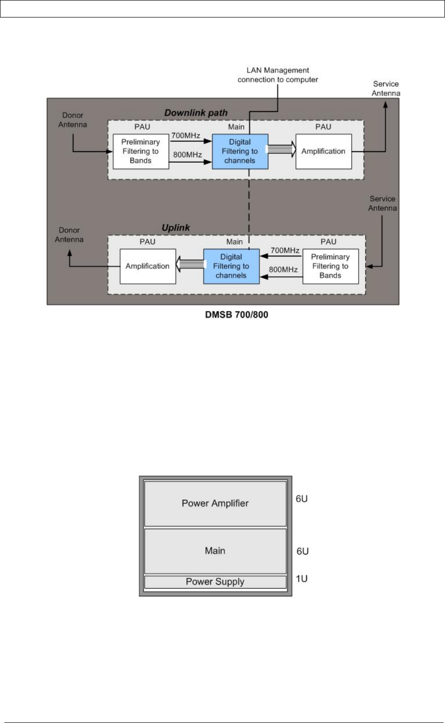
1.3 ARCHITECTURE
Deko4078SD comprises the following main units:
• PAU (Power Amplifier Unit) – provides interface to the (Donor and Service)
antennas and provides isolation between the uplink and downlink signals.
In the downlink - performs the preliminary filtering to (700 or 800) bands.
In the uplink – amplifies the signal.
• Main unit – performs the digital filtering and provides management and
control functions
• Power Supply – supplies power to the Main unit
PRODUCT MANUAL DEKO4078SD MULTI-CHANNEL SIGNAL BOOSTER DEKOLINK WIRELESS LTD.
P/N 300SC30031 Rev. 1.2 Proprietary Data Page 11
The following figure shows the operation flow in the downlink path and the uplink
path.
1.4 DEKO4078SD ELEMENTS
The elements are installed in a 19 inch cabinet and are supplied with the necessary
connections except for the RF antenna connections, power (AC outlet) and dry
contact alarm connections (the dry-contact alarm cable is supplied with the
accessories).
The LEDd of the system elements are all in the front, and the ports and connectors
are accessed from the rear.
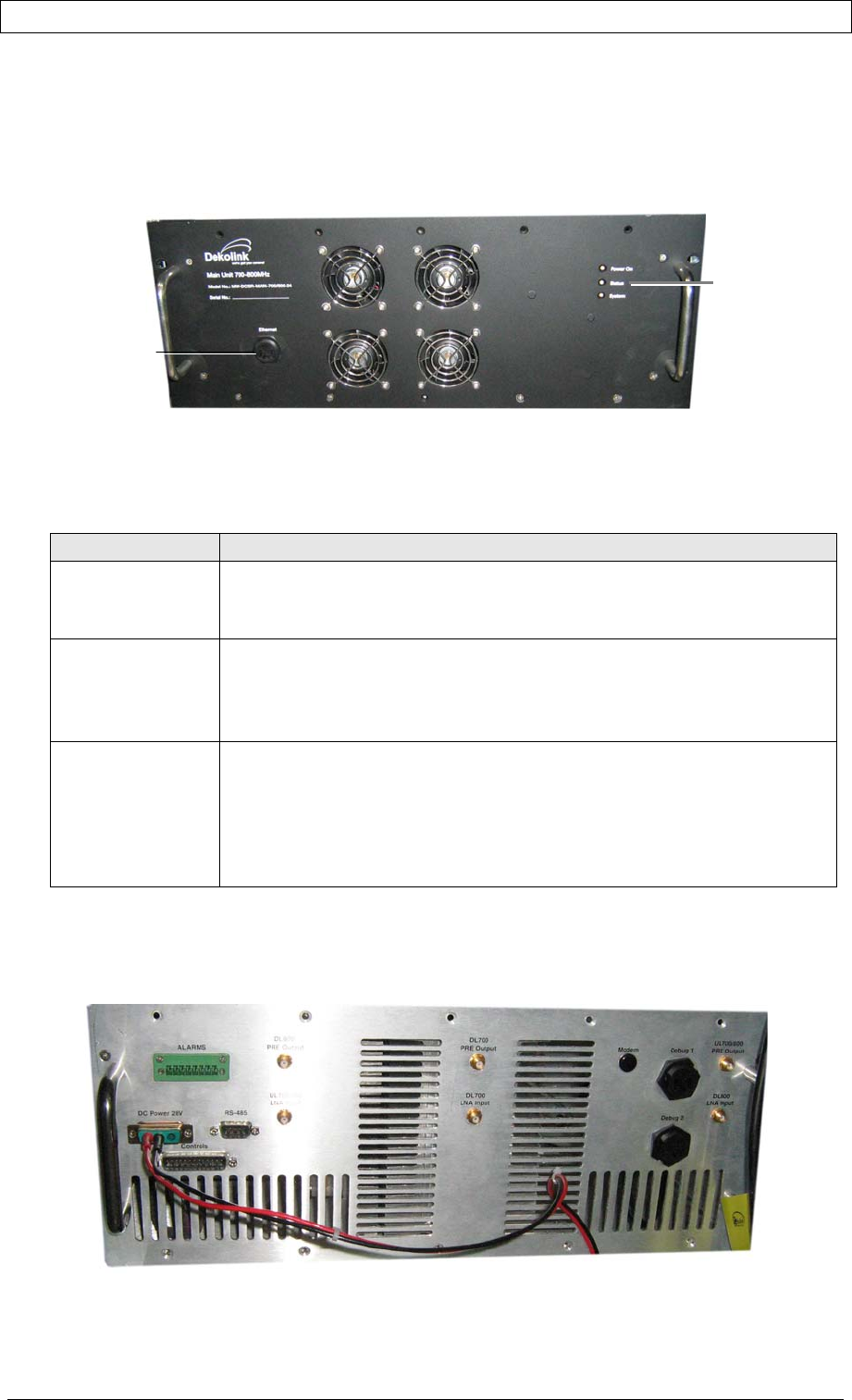
The following figure shows an example of a typical Deko4078SD cabinet
configuration.
Figure 2. Typical Deko4078SD Cabinet Configuration
PRODUCT MANUAL DEKO4078SD MULTI-CHANNEL SIGNAL BOOSTER DEKOLINK WIRELESS LTD.
Page 12 Proprietary Data P/N 300SC30031 Rev. 1.2
1.4.1 MAIN UNIT
1.4.1.1 Front Panel Interfaces
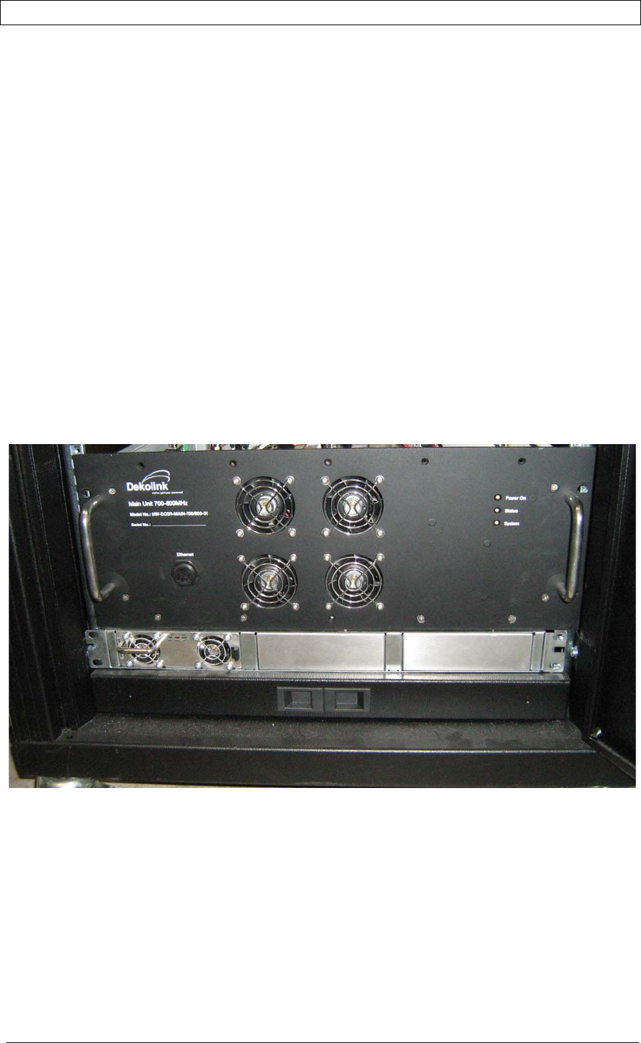
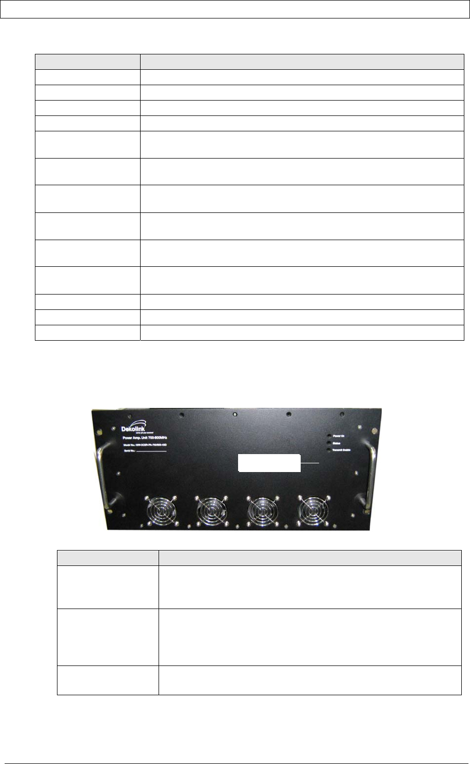
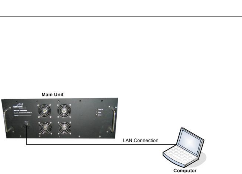
The front panel includes the LED indicators and Ethernet port (for service personnel).
Figure 3. Main Unit Front Panel
The following table provides a brief description the front panel indicators.
Table 3. Main Unit Front Panel Indicators
Status Indicator Description
Power On Main drawer power supply:
GREEN - Power On
GRAY – Power Off
Status Main drawer status:
GREEN – All statuses are OK (no alarms)
ORANGE – Minor malfunction
RED – Major malfunction
System Service status:
GREEN - System ready for normal operation (if this LED is not green the
system will not operate).
RED – No service. Major malfunction at Main or Power Amplifier drawer
Note: If the System LED is red but the Status LED is not then this
indicates a problem at the Power Amplifier unit.
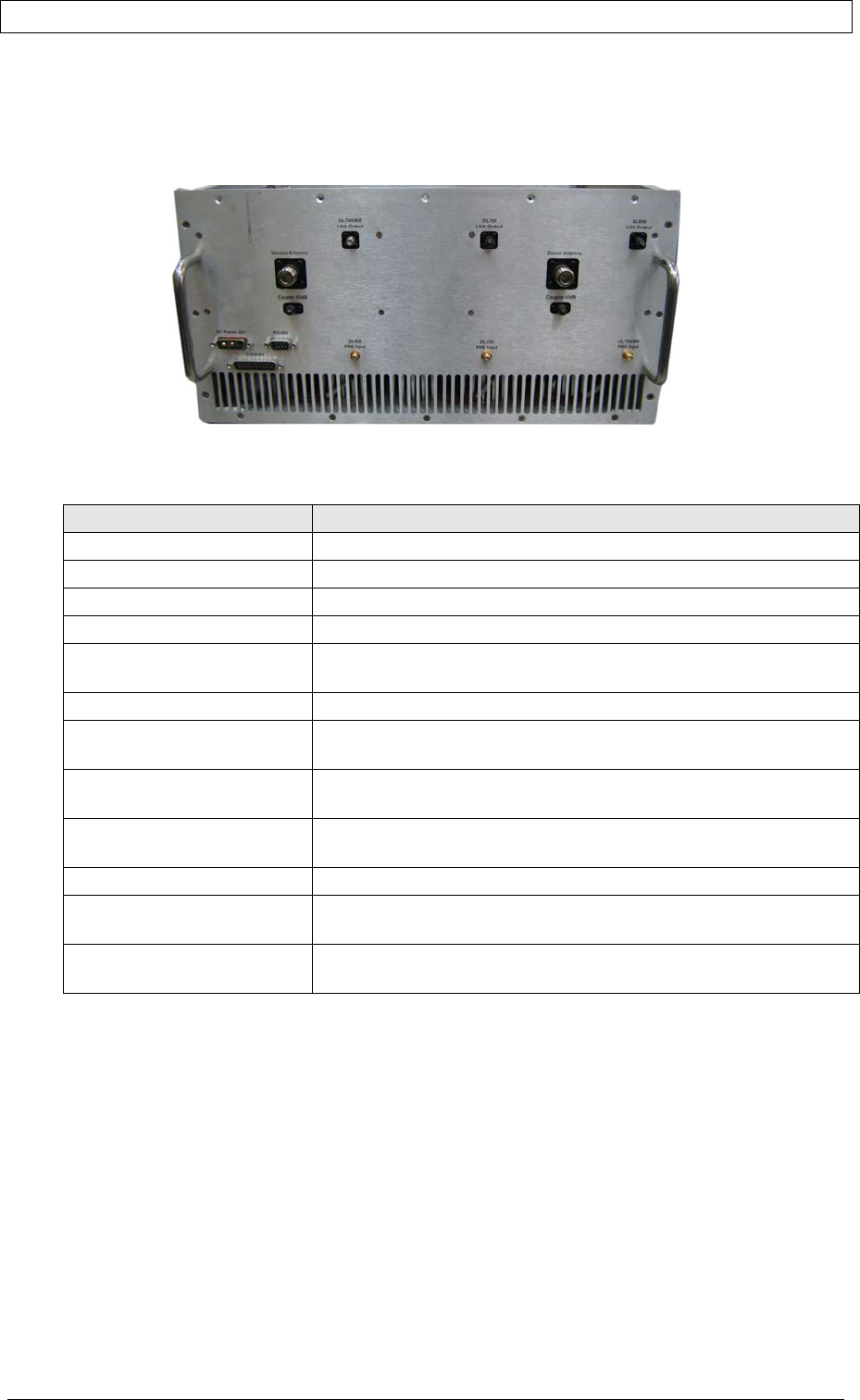
1.4.1.2 Rear Panel Interfaces
The rear panel contains the RF connections, power connections and dry-contact
alarms.
Figure 4. 700/800 DMSB UHF Rear Panel
Status
indicators
Ethernet port fo
r
mana
g
emen
t
PRODUCT MANUAL DEKO4078SD MULTI-CHANNEL SIGNAL BOOSTER DEKOLINK WIRELESS LTD.
P/N 300SC30031 Rev. 1.2 Proprietary Data Page 13
The following table provides a description of the rear panel ports.
Indicator (alarm) Description
Alarms Dry-contact alarm connections (if necessary)
DC Power 28V 28 V DC; 12A
RS485 For Dekolink service personnel
Controls For Dekolink service personnel
DL 800 Pre Output SMA Male Connector – connection to PAU DL800 Pre Input
connector
DL 700 Pre Output SMA Male Connector – connection to PAU DL700 Pre Input
connector
UL 700-800 LNA
Input
SMA Male Connector - connection to PAU UL 700/800 LNA Output
connector
DL 700 LNA Input SMA Male Connector – connection to PAU DL700 Pre LNA Output
connector
UL 700/800 Pre
Output
SMA Male Connector – connection to PAU UL700/800 Pre Input
connector
DL 800 LNA Input SMA Male Connector – connection to PAU DL 800 LNA Output
connector
Modem Future option
Debug 1 N/A - For Dekolink Service Personnel
Debug 2 N/A - For Dekolink Service Personnel
1.4.2 POWER AMPLIFIER UNIT
1.4.2.1 Front Panel Interfaces
The front panel includes the power amplifiers’ status LEDs.
The following table provides a description of the status indicators.
Status Indicator Description
Power On Power supply of P.Amp drawer:
GREEN - Power On
GRAY – Power Off
Status Status of P.Amp drawer:
GREEN - OK
ORANGE – Minor malfunction
RED – Major malfunction
Transmit Enable GREEN - System is operable and transmitting a signal
GRAY – No transmission (at all domains – 700 DL; 800DL; UL)
Status LEDs
PRODUCT MANUAL DEKO4078SD MULTI-CHANNEL SIGNAL BOOSTER DEKOLINK WIRELESS LTD.
Page 14 Proprietary Data P/N 300SC30031 Rev. 1.2
1.4.2.2 Rear Panel Interfaces
The power amplifier rear panel includes the interfaces to the Main unit and to the
Donor/Base and Service/Mobile antennas.
Figure 5. Power Amplifier Rear Panel
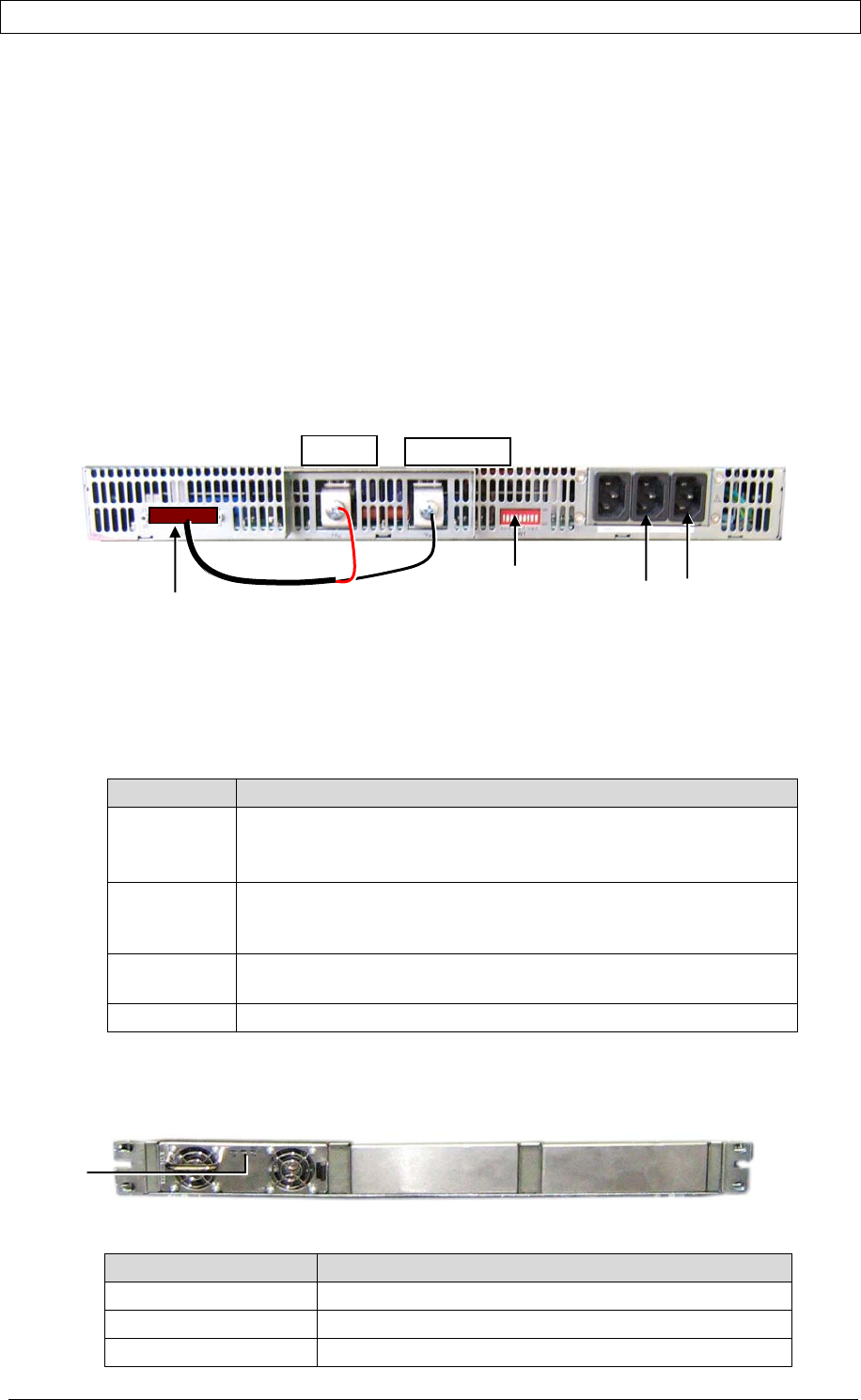
The following table provides a description of the rear panel ports.
Indicator (alarm) Description
DC Power 28V 28 V DC; 12A
RS485 For Dekolink service personnel
Controls For Dekolink service personnel
Service Antenna RF connection to Service/Mobile antenna
(Service) Coupler
(Service/Donor) 40dB
Coupling connectors (40 dB). Used to test input signals from the
Base and Mobile antennas.
Donor Antenna RF connection to Donor/Base antenna
UL 700/800 LNA Output SMA Male connector - connection to Main unit rear panel UL
700/800 LNA Input connector
DL 700 LNA Output SMA Male connector - connection to Main unit rear panel
DL700 LNA Input connector
DL 800 LNA Output SMA Male connector - connection to Main unit rear panel
DL800 LNA Input connector
DL 800 Pre Input SMA Male connector - connection to Main unit
DL 700 Pre Input SMA Male connector – connection to Main unit rear panel
DL700 Pre Output connector
UL 700/800 Pre Input SMA Male connector – connection to Main unit rear panel
UL700/800 Pre Output connector
PRODUCT MANUAL DEKO4078SD MULTI-CHANNEL SIGNAL BOOSTER DEKOLINK WIRELESS LTD.
P/N 300SC30031 Rev. 1.2 Proprietary Data Page 15
1.4.3 POWER SUPPLY INTERFACES
The power supply feeds the power DIRECTLY to the Main unit and is provided with 1
to 3 installed (power) modules (for redundancy) which are preconfigured according
to the installation.
The figure below shows the Power Supply rear panel.
The figure below shows the Power Supply rear panel. Note that the dipswitches are
factory set according to the installation and should not be modified. The DB25 J1
connector is connected to the +V DC and –V DC (Ret) connectors from which
power is distributed to the Main unit.
Figure 6. Power Supply Rear Panel
1.4.3.1 Rear Panel
The Power Supply rear panel connectors are accessed from the rear of the cabinet.
The following table provides a description of the rear panel connectors.
CONNECTOR DESCRIPTION
J1 25-pin connector. Output power.
If not already connected, the supplied accessory cable
should be connected to +V DC and –V DC Ret.
AC Main 110/220 AC power connections corresponding to the power
units. Each connector corresponds to the parallel internal power
supply module.
+V DC and
-V DC (Ret)
Connections to the Main unit
SW1 Not Applicable.
1.4.3.2 Front Panel
The Power Supply front panel contains the unit fans and three status LEDs.
Figure 7. Power Supply Front Panel
POWER SUPPLY LED DESCRIPTION
DC OK GREEN – NORMAL OPERATION
DC FAIL RED - MALFUNCTION
AC OK GREEN – NORMAL OPERATION
Status
LEDs
DB25 J1 Factory set
Dipswitches –
do not modify!
+V DC -V DC (Ret)
To AC outlet(s)

PRODUCT MANUAL DEKO4078SD MULTI-CHANNEL SIGNAL BOOSTER DEKOLINK WIRELESS LTD.
Page 16 Proprietary Data P/N 300SC30031 Rev. 1.2
2 SITE AND INSTALLATION REQUIREMENTS
This section provides information on the site installation considerations and
requirements.
It is recommended to review the procedures described in this section before
installing, deploying or operating the system.
2.1 RACK INSTALLATION, ENVIRONMENT AND CABLES
• Follow all local safety regulations when installing the system.
• Follow Electro-Static Discharge (ESD) precautions.
• Install the DMSB 700/800 MHz amplifier close to the service area to monitor
the output power and noise figure.
• It is recommended that the installation location be as close as possible to the
antenna site in order to minimize cable loss.
• Use low loss cables to perform the RF connections
• Install the units (or place the cabinet with installed units) in a shielded and
ventilated area.
• Only trained and qualified personnel should be allowed to install or replace this
equipment.
• Verify that ambient temperature of the environment does not exceed 50°C
(122°F)
• Ensure that adequate airflow and ventilation within the rack and around the
installed components so that the safety of the equipment is not compromised.
2.2 ANTENNA REQUIREMENTS
2.2.1 BASE (DONOR) ANTENNA
The Base (Donor) antenna is usually installed outdoors and is either a directional
antenna such as a Yagi or a Panel antenna.
Donor Antenna specifications:
• Yagi type or similar – 10 to 15 dBi gain, very sharp beam pointed to the BTS.
• Cable and jumper loss is at least 2dB.
• The required Base signals should be the dominant signals; at least 6 dB higher
power than other signals.
• Example of antenna's typical specifications:
Gain: 8 dBd (=10 dBi)
VSWR: < 1:5:1
Impedance: 50 ohm
2.2.2 MOBILE (SERVICE) ANTENNA
The Mobile antenna is installed indoors.
Note: Before installing the Mobile antenna, see FCC regulations for information
regarding recommended distances between the antennas and populated areas.
The following describes the requirements for an omni-directional mobile used for
indoor applications.

PRODUCT MANUAL DEKO4078SD MULTI-CHANNEL SIGNAL BOOSTER DEKOLINK WIRELESS LTD.
P/N 300SC30031 Rev. 1.2 Proprietary Data Page 17
Specifications:
• Omni directional antenna with 2.2 dBi typical gain.
• Example of omni-directional antenna specifications:
Gain: 2.2 dBi
VSWR: < 2:1
Impedance: 50 ohm
2.3 GROUNDING WIRES REQUIREMENTS
Note: The grounding requirements are only relevant for the rack installation where the
system elements are not supplied with the required connections.
Requirements for grounding wires
• Protective grounding conductor - should be aluminum with cross-section
10AWG.
• Lug of the protective grounding conductor - should be aluminum
• Washers and screw - should be high Cr stainless steel, or 12% Cr stainless steel, or
Cr on, Ni on steel, tin on steel
2.4 RF CABLE INSTALLATION GUIDELINES
Required:
• For all coaxial connections to/from the Booster - high performance, flexible,
low loss 50Ω coaxial communications cable.
• All cables shall be weather-resistant type.
• Cable length - determined by the Booster installation plan. When calculating
the cable length, take into account excess cable slack so as not to limit the
insertion paths.

PRODUCT MANUAL DEKO4078SD MULTI-CHANNEL SIGNAL BOOSTER DEKOLINK WIRELESS LTD.
Page 18 Proprietary Data P/N 300SC30031 Rev. 1.2
3 PHYSICAL INSTALLATION
This section describes the installation procedure for the Dekolink 700/800 DMSB
system.
3.1 OVERVIEW
The system is supplied in a cabinet with the required connections.
For this type of system, the installation procedure consists of:
1. Selecting a location for the system according to the requirements described in
Chapter- 2 .
2. Unpacking the cabinet system (see 3.2)
3. Connecting the Donor and Service antennas (see 3.3)
4. Verifying that the ground is connected (see 3.4)
5. Connecting the wall power outlet to the power-supply (see 3.5)
Important: Be sure to perform the power supply connection last, otherwise damage
may be caused to the system!
6. Commission the system. See Chapter 4 .
It is important to perform the installation procedure according to the order described
above.
3.2 UNPACKING
Upon receiving the Deko4078SD Signal Booster, perform the following:
1. Examine the shipping container for damage before unpacking the unit.
2. Perform a visual inspection to reveal any physical damage to the equipment.
3. Verify that all of the equipment (listed below) is included. Otherwise contact
Dekolink Wireless Ltd.
Deko4078SD is shipped with the equipment listed in the supplied parts list document.
PRODUCT MANUAL DEKO4078SD MULTI-CHANNEL SIGNAL BOOSTER DEKOLINK WIRELESS LTD.
P/N 300SC30031 Rev. 1.2 Proprietary Data Page 19
3.3 CONNECTING THE DONOR AND SERVICE ANTENNAS
CAUTION
DO NOT CONNECT THE ANTENNA CABLES TO THE BOOSTER BEFORE VERIFYING THE INSTALLATION
PARAMETERS - SPECIFICALLY THE ISOLATION BETWEEN THE ANTENNAS.
DO NOT POWER-ON THE BOOSTER (USING THE INTERNAL SWITCH) WITHOUT EITHER THE
ANTENNAS BEING CONNECTED OR THE ANTENNA CONNECTIONS TERMINATED WITH DUMMY LOADS.
Note: If the coaxial cables are NOT weather-resistant type, wrap the exterior coaxial
cables with insulation and holding tape (Type 3M Rubber splicing tape) for
environmental protection and to ensure longer lifetime.
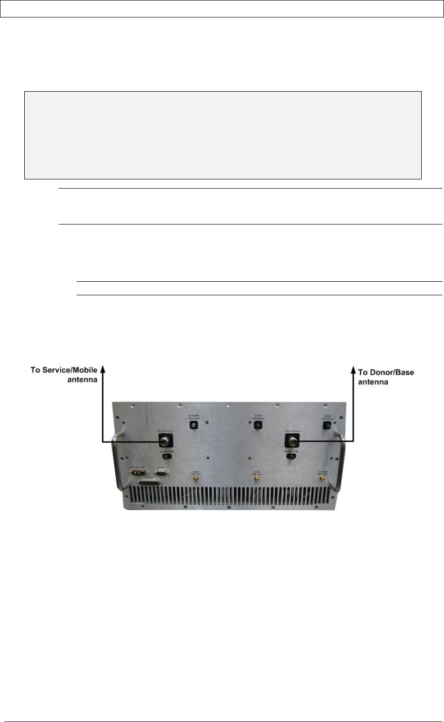
To connect the antennas to the Power Amplifier
1. Install the antenna cables along their path to the Power Amplifier unit, and
connect them to the Antennas.
Note: Be sure to use low loss cables.
2. Connect the Donor antenna to the BASE port.
3. Connect the Service antenna to the MOBILE port.
4. Verify all RF connectors are tightened and the cables and antennas are secured
Figure 8. Power Amplifier and Antenna Connections
PRODUCT MANUAL DEKO4078SD MULTI-CHANNEL SIGNAL BOOSTER DEKOLINK WIRELESS LTD.
Page 20 Proprietary Data P/N 300SC30031 Rev. 1.2
3.4 VERIFYING GROUND CONNECTIONS
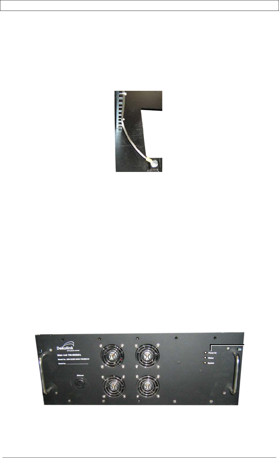
All of the units’ grounding lugs are located on the left side of their rear panels. The
Deko4078SD units’ ground connections are interconnected and the final grounding
connection is performed to the cabinet rack grounding lug located on the left side of
the bottom shelf (accessed from the rear). See below.
Figure 9. Final Grounding Connection
In addition, it is required to connect the rack ground to the building ground.
3.5 POWER UP
ATTENTION!
Be sure that grounding is performed properly and
that all required RF connections (Donor and Service
antennas in case of a supplied cabinet installation)
before powering-up the units
1. Connect the power connector on the Power Supply rear panel to a 220/110 VAC
power source.
2. Maintain the Main unit in idle state (after power up) for approximately one or
two minutes. This time lapse is required for the CPU boot up. After the boot-up
process is complete, the SYSTEM READY GREEN LED will light.
3. Verify that the PWR ON LED on the Main unit front panel is GREEN.
Power On
indicator
4 COMMISSIONING THE SYSTEM
This section provides the initialization and setup procedures for the Deko4078SD
signal booster. The procedures are performed through an Ethernet connection
between the Deko4078SD signal booster and a computer.
Note. This chapter only describes the parameters required to provision the Deko4078SD
signal booster. The application window options are fully described in Chapter- 5 .
4.1 OPENING A SESSION
4.1.1 CONNECTING THE SIGNAL BOOSTER TO THE COMPUTER
To open connect the Signal Booster to the Computer
Connect the Ethernet cable (supplied) between the Main units’ front panel Ethernet
port (see figure below) and the computer Ethernet port.
Figure 10. Connection to Computer
4.1.2 CONFIGURE THE COMPUTER NETWORK PARAMETERS
You will now configure the computer network parameters to communicate with the
Booster. Note that the procedure may vary slightly depending on the operating
system installed on your computer. The following procedure is for Windows XP.
To configure the computer’s network parameters:
1. Click the Start menu and choose Control Panel.
2. In the Control Panel, click Network and Internet Connections.
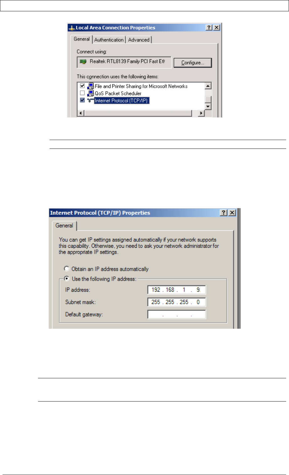
3. Click Network Connections and then double-click Local Area Connection
The Local Area Connections Properties dialog appears with the General tab
displayed by default.
PRODUCT MANUAL DEKO4078SD MULTI-CHANNEL SIGNAL BOOSTER DEKOLINK WIRELESS LTD.
Page 22 Proprietary Data P/N 300SC30031 Rev. 1.2
4. In the Items list, select “Internet Protocol (TCP*IP)” and click the
Properties button. The “Internet Protocol (TCP/IP) Properties” dialog appears.
Note: The Booster is supplied with the default IP address 192.168.1.253.
5. Assign your computer an IP address in the same subnet, in order to
communicate with the unit.
• In the IP address area:
• Enter the IP address 192.168.1.x, where ‘x’ can be any number between 2 and
250 inclusive. For example, (192.168.1.9)
• Define the subnet mask as shown (255.255.255.0)
• Click OK.
The computer communication parameters are now defined and you can open a
session to the Booster.
4.1.3 LOGIN TO THE SIGNAL BOOSTER
NOTE: The booster is factory assigned the address 192.168.1.253. You will login for the
first time using this address and make the necessary modifications according to
information provided by your network administrator.
To login to the booster
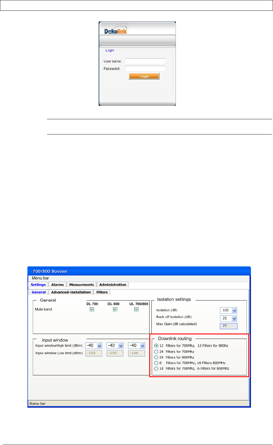
1. Open one of the Flash-enabled browsers listed in the system requirements.
2. In the address line, enter the provided IP address of the Booster. A session will
be established with the Booster an the login dialog appears.
PRODUCT MANUAL DEKO4078SD MULTI-CHANNEL SIGNAL BOOSTER DEKOLINK WIRELESS LTD.
P/N 300SC30031 Rev. 1.2 Proprietary Data Page 23
3. Type the default User Name admin and the default Password admin
Note: Both User name and Password are case sensitive and must be entered with
lower case letters.
4. Click Login. The application main window appears.
4.2 COMMISSIONING THE SYSTEM
The commissioning procedure consists of the following steps
for each
Deko4078SD:
1. Configuring the Booster parameters
2. Verifying that there are no alarms in the alarms area of the management
application and configuring the signal booster general parameters.
3. Configuring the required filters
4. Configuring the Modem parameters (if installed)
4.2.1 CONFIGURING THE BOOSTER PARAMETERS
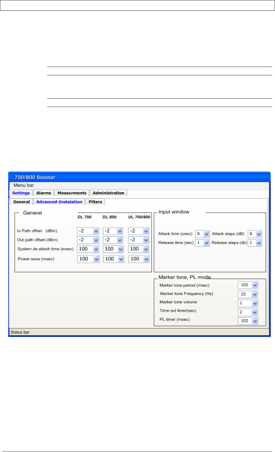
1. Click the
General
tab of the Settings window and verify that the UL and DL
bands in the General field area are enabled.
Figure 11. General Settings Tab
PRODUCT MANUAL DEKO4078SD MULTI-CHANNEL SIGNAL BOOSTER DEKOLINK WIRELESS LTD.
Page 24 Proprietary Data P/N 300SC30031 Rev. 1.2
2. In the
Isolation Settings
field area, determine the Isolation and Back off
isolation parameters. The application calculates the Max gain (dB) accordingly.
3. In the
Input Window
field area, configure the Input window High Limit
parameter which determines the signal boosters’ signal range. The Low limit is
automatically determined according to the configured
High limit
.
Note: The attack and release times can be configured. See Step 5.
4. Determine the number of filters to be allocated for each band. Select the
required filter configuration in the Downlink Routing field area.
Note: The default setting is 12 Filter for 700MHz, 12 Filters for 800MHz.
The filter configuration selected here determines the maximum number of filters
that can be added when configuring the filters for the 700 and 800 bands (see
4.2.3).
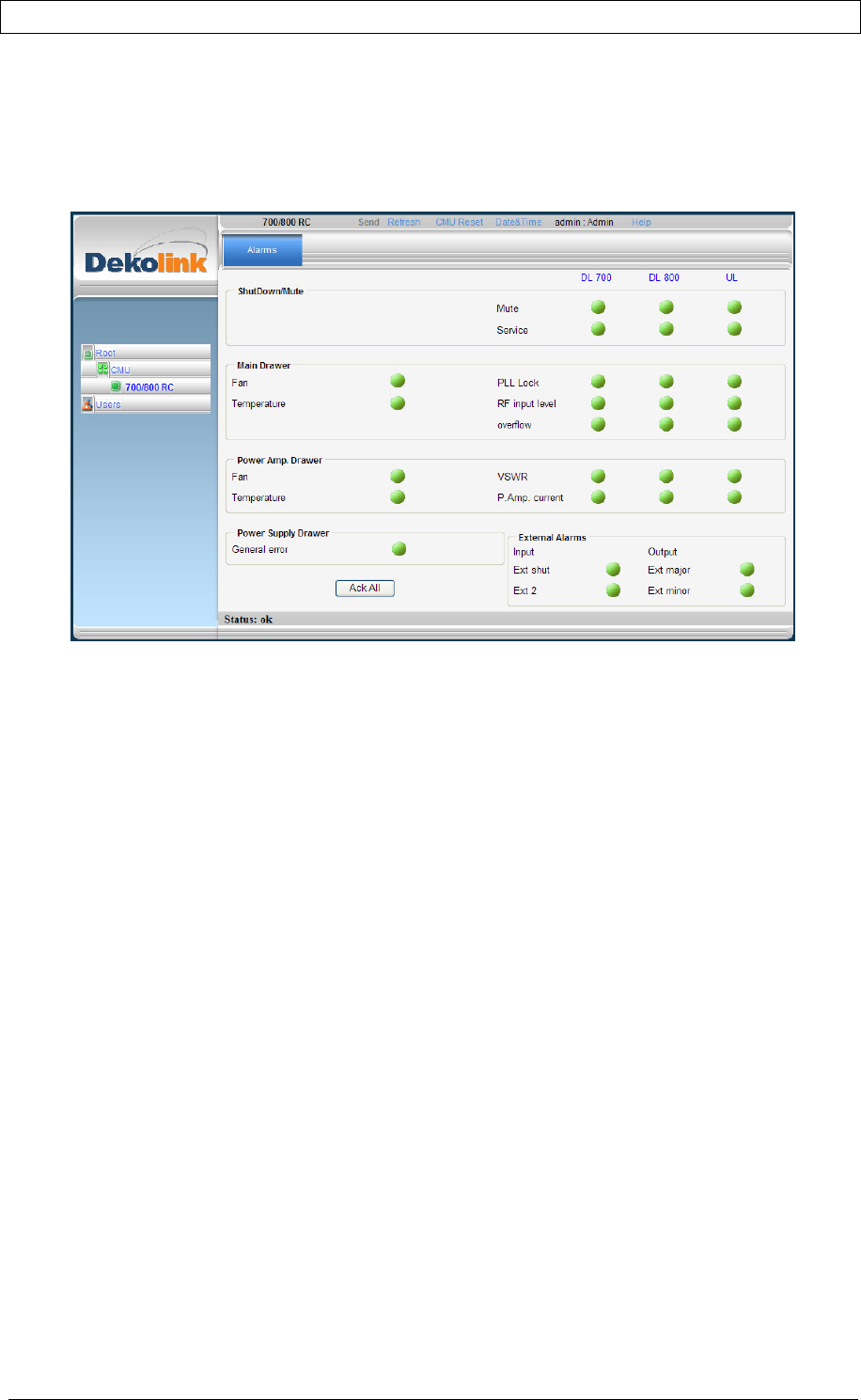
5. Click the Advanced Installation window and define the parameters displayed
in the
General
(i.e.
in Path offset
) and
Marker Tone, PL Mode
(For analog – FM)
field areas. In addition, the
Attack
and
Release
times can be configured for the
input signal range determined in the
General Settings
tab.
Figure 12. Advanced Installation Tab
PRODUCT MANUAL DEKO4078SD MULTI-CHANNEL SIGNAL BOOSTER DEKOLINK WIRELESS LTD.
P/N 300SC30031 Rev. 1.2 Proprietary Data Page 25
4.2.2 VIEWING ALARMS
Click the Alarms tab and verify that all the alarms displayed in the
Summary View
screen are green.
Figure 13. Alarms Summary View
PRODUCT MANUAL DEKO4078SD MULTI-CHANNEL SIGNAL BOOSTER DEKOLINK WIRELESS LTD.
Page 26 Proprietary Data P/N 300SC30031 Rev. 1.2
4.2.3 CONFIGURING THE FILTERS
The DMSB Management Tool enables selecting up to a total of 24 filters for the 700
and 800 bands and provides five available configuration options to choose from
(downlink routing). The default downlink routing setting is
12 filters for 700MHz, 12
Filters for 800MHz
. Upon initial installation there are no filters listed and they must
be added. In addition, when the user re-routes the system, the filter assignment map
is deleted and must be reset.
To configure the required filters
Note: The number of filters that can be defined depends on the selected DL Routing
configuration (see 4.2.1 step 4). For example, if the 12 filters for 700MHz, 12 Filters for
800MHz option was selected then the maximum number of filters that can be added for
each band is 12.
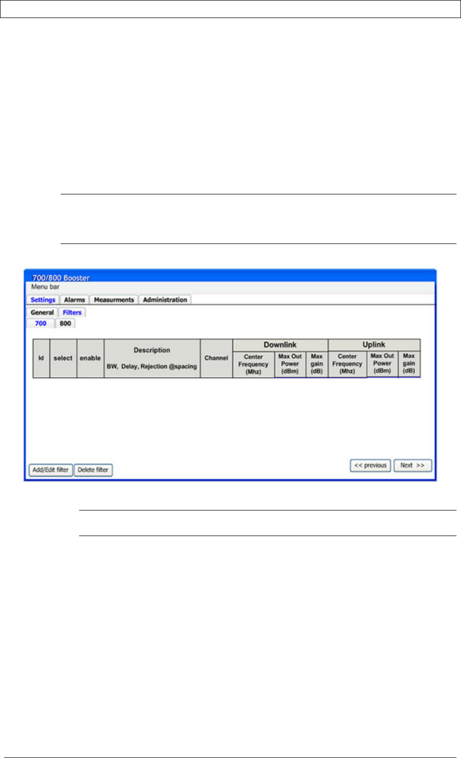
1. Click the Filters tab of the
Setting
window, the following window appears.
Figure 14. Filters Tab
Note: The filter configuration for the 700 and 800 bands is performed for each one in
their corresponding windows.
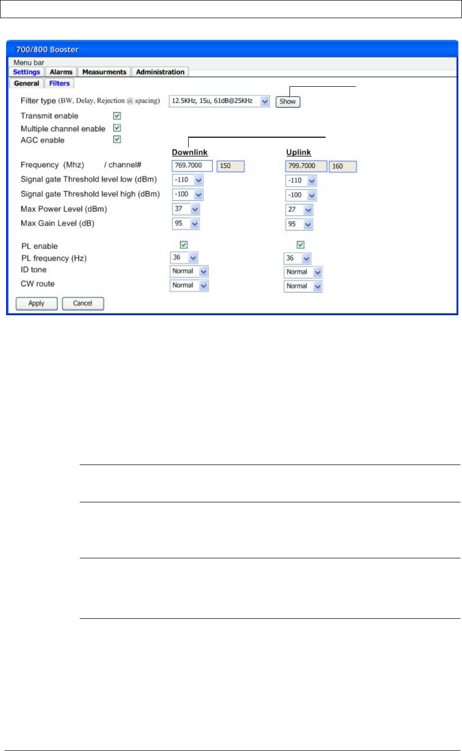
2. To add a filter, click the Add/Edit Filter button. The following window appears.
PRODUCT MANUAL DEKO4078SD MULTI-CHANNEL SIGNAL BOOSTER DEKOLINK WIRELESS LTD.
P/N 300SC30031 Rev. 1.2 Proprietary Data Page 27
Figure 15. Add/Edit Filter Window
The filter parameters are displayed with default values, however these may be
modified. Note that the filter PL enable parameter is
disabled
by default.
3. Select the required filter from the Filter Type field drop-down list according to
the following:
• Bandwidth
• Delay
• Rejection at spacing
Note: The Filter screen includes a Show button that provides several display types
(i.e. filter pass band and rejection plots), enabling viewing the filter properties and
characteristics to ensure a proper selection of the filter.
4. Define the DL center frequency in the Frequency field. The corresponding UL
center frequency is automatically defined.
5. Verify that the Transmit Enable checkbox is enabled.
Note 1: If the Transmit Enable parameter is not enabled then the filter will be
defined but not operable.
Note 2: The maximum output power of a channel depends on the number of defined
filters. Upon defining new filter, the system will provide a warning regarding
the new limit of maximum output power available for each filter.
6. The default filter Max Gain value displayed is the Maximum Gain calculated
according to the isolation settings (see section 4.2.1 step 2). This value can be
modified, however the filter Maximum Gain cannot be higher than that calculated
according to the booster isolation settings. If a higher maximum gain value is
required the isolation settings must be modified accordingly.
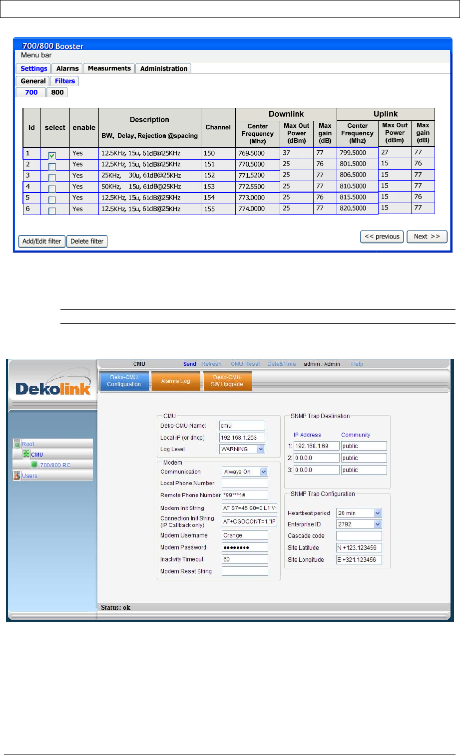
7. Click Apply. The selected filter and description are displayed, as shown below.
Click to view graph
of filter
characteristics.
Center Frequency
PRODUCT MANUAL DEKO4078SD MULTI-CHANNEL SIGNAL BOOSTER DEKOLINK WIRELESS LTD.
Page 28 Proprietary Data P/N 300SC30031 Rev. 1.2
Figure 16. Filter Description
4.2.4 CONFIGURING THE MODEM PARAMETERS
NOTE: This section is relevant only if a modem is connected.
1. Click the Deko-CMU Communication tab of the
CMU
window. The following
window appears.
Figure 17. Communication Parameters Window

PRODUCT MANUAL DEKO4078SD MULTI-CHANNEL SIGNAL BOOSTER DEKOLINK WIRELESS LTD.
P/N 300SC30031 Rev. 1.2 Proprietary Data Page 29
2. Define the following modem communication parameters:
• Communication – Fixed IP
• Local Phone Number
• Remote Phone Number
• Modem Password
3. Click Apply.
4.3 VERIFYING SITE COVERAGE
Once the installation is complete, verify coverage on site.
Deko4078SD enables you to transmit an ID tone on each channel in order to verify
coverage on that channel using a continuous tone. See section 6.1.