Dell Integrated Remote Access Controller 7 (iDRAC7) Version 1.50.50 User's Guide 1507979649integrated Cntrllr V1.50.50 En Us
User Manual: Dell DELL IDRAC 7 pdf | FreeUserManuals.com
Open the PDF directly: View PDF ![]() .
.
Page Count: 258 [warning: Documents this large are best viewed by clicking the View PDF Link!]
- Integrated Dell Remote Access Controller 7 (iDRAC7) Version 1.50.50 User's Guide
- Overview
- Benefits of Using iDRAC7 With Lifecycle Controller
- Key Features
- New In This Release
- How To Use This User's Guide
- Supported Web Browsers
- Managing Licenses
- Licensable Features In iDRAC7
- Interfaces and Protocols to Access iDRAC7
- iDRAC7 Port Information
- Other Documents You May Need
- Social Media Reference
- Contacting Dell
- Accessing Documents From Dell Support Site
- Logging into iDRAC7
- Logging into iDRAC7 as Local User, Active Directory User, or LDAP User
- Logging into iDRAC7 Using Smart Card
- Logging into iDRAC7 Using Single Sign-on
- Accessing iDRAC7 Using Remote RACADM
- Accessing iDRAC7 Using Local RACADM
- Accessing iDRAC7 Using Firmware RACADM
- Accessing iDRAC7 Using SMCLP
- Logging in to iDRAC7 Using Public Key Authentication
- Multiple iDRAC7 Sessions
- Changing Default Login Password
- Enabling or Disabling Default Password Warning Message
- Setting Up Managed System and Management Station
- Setting Up iDRAC7 IP Address
- Setting Up Management Station
- Setting Up Managed System
- Configuring Supported Web Browsers
- Updating Device Firmware
- Downloading Device Firmware
- Updating Firmware Using iDRAC7 Web Interface
- Updating Device Firmware Using RACADM
- Scheduling Automatic Firmware Updates
- Updating Firmware Using CMC Web Interface
- Updating Firmware Using DUP
- Updating Firmware Using Remote RACADM
- Updating Firmware Using Lifecycle Controller Remote Services
- Viewing and Managing Staged Updates
- Rolling Back Device Firmware
- Backing Up Server Profile
- Importing Server Profile
- Monitoring iDRAC7 Using Other Systems Management Tools
- Configuring iDRAC7
- Viewing iDRAC7 Information
- Modifying Network Settings
- Configuring Services
- Using VNC Client to Manage Remote Server
- Configuring Front Panel Display
- Configuring Time Zone and NTP
- Setting First Boot Device
- Enabling or Disabling OS to iDRAC Pass-through
- Obtaining Certificates
- Configuring Multiple iDRAC7s Using RACADM
- Disabling Access to Modify iDRAC7 Configuration Settings on Host System
- Viewing iDRAC7 and Managed System Information
- Viewing Managed System Health and Properties
- Viewing System Inventory
- Viewing Sensor Information
- Checking the System for Fresh Air Compliance
- Viewing Historical Temperature Data
- Inventory and Monitoring Storage Devices
- Inventory and Monitoring Network Devices
- Inventory and Monitoring FC HBA Devices
- Viewing FlexAddress Mezzanine Card Fabric Connections
- Viewing or Terminating iDRAC7 Sessions
- Setting Up iDRAC7 Communication
- Communicating With iDRAC7 Through Serial Connection Using DB9 Cable
- Switching Between RAC Serial and Serial Console While Using DB9 Cable
- Communicating With iDRAC7 Using IPMI SOL
- Communicating With iDRAC7 Using IPMI Over LAN
- Enabling or Disabling Remote RACADM
- Disabling Local RACADM
- Enabling IPMI on Managed System
- Configuring Linux for Serial Console During Boot
- Supported SSH Cryptography Schemes
- Configuring User Accounts and Privileges
- Configuring Local Users
- Configuring Active Directory Users
- Prerequisites for Using Active Directory Authentication for iDRAC7
- Supported Active Directory Authentication Mechanisms
- Standard Schema Active Directory Overview
- Configuring Standard Schema Active Directory
- Extended Schema Active Directory Overview
- Configuring Extended Schema Active Directory
- Testing Active Directory Settings
- Configuring Generic LDAP Users
- Configuring iDRAC7 for Single Sign-On or Smart Card Login
- Configuring iDRAC7 to Send Alerts
- Managing Logs
- Monitoring and Managing Power
- Configuring and Using Virtual Console
- Managing Virtual Media
- Installing and Using VMCLI Utility
- Managing vFlash SD Card
- Using SMCLP
- Using iDRAC Service Module
- Deploying Operating Systems
- Troubleshooting Managed System Using iDRAC7
- Using Diagnostic Console
- Viewing Post Codes
- Viewing Boot and Crash Capture Videos
- Viewing Logs
- Viewing Last System Crash Screen
- Viewing Front Panel Status
- Hardware Trouble Indicators
- Viewing System Health
- Generating Tech Support Report
- Checking Server Status Screen for Error Messages
- Restarting iDRAC7
- Resetting iDRAC7 to Factory Default Settings
- Frequently Asked Questions
- Use Case Scenarios
- Troubleshooting An Inaccessible Managed System
- Obtaining System Information and Assess System Health
- Setting Up Alerts and Configuring Email Alerts
- Viewing and Exporting Lifecycle Log and System Event Log
- Interfaces to Update iDRAC Firmware
- Performing Graceful Shutdown
- Creating New Administrator User Account
- Launching Server's Remote Console and Mounting a USB Drive
- Installing Bare Metal OS Using Attached Virtual Media and Remote File Share
- Managing Rack Density
- Installing New Electronic License
- Applying I/O Identity Configuration Settings for Multiple Network Cards in Single Host System Reboot

Integrated Dell Remote Access Controller 7 (iDRAC7)
Version 1.50.50 User's Guide

Notes, Cautions, and Warnings
NOTE: A NOTE indicates important information that helps you make better use of your computer.
CAUTION: A CAUTION indicates either potential damage to hardware or loss of data and tells you how to avoid the
problem.
WARNING: A WARNING indicates a potential for property damage, personal injury, or death.
Copyright © 2014 Dell Inc. All rights reserved. This product is protected by U.S. and international copyright and intellectual property
laws. Dell™ and the Dell logo are trademarks of Dell Inc. in the United States and/or other jurisdictions. All other marks and names
mentioned herein may be trademarks of their respective companies.
2013 - 12
Rev. A00
Contents
1 Overview.....................................................................................................................................15
Benefits of Using iDRAC7 With Lifecycle Controller...............................................................................................15
Key Features........................................................................................................................................................... 16
New In This Release...............................................................................................................................................17
How To Use This User's Guide............................................................................................................................... 18
Supported Web Browsers...................................................................................................................................... 19
Managing Licenses ................................................................................................................................................19
Types of Licenses.............................................................................................................................................19
Acquiring Licenses...........................................................................................................................................19
License Operations.......................................................................................................................................... 19
Licensable Features In iDRAC7.............................................................................................................................. 21
Interfaces and Protocols to Access iDRAC7..........................................................................................................23
iDRAC7 Port Information.........................................................................................................................................25
Other Documents You May Need........................................................................................................................... 26
Social Media Reference.........................................................................................................................................27
Contacting Dell....................................................................................................................................................... 27
Accessing Documents From Dell Support Site.......................................................................................................27
2 Logging into iDRAC7................................................................................................................. 29
Logging into iDRAC7 as Local User, Active Directory User, or LDAP User............................................................ 29
Logging into iDRAC7 Using Smart Card.................................................................................................................. 30
Logging Into iDRAC7 as a Local User Using Smart Card................................................................................. 30
Logging Into iDRAC7 as an Active Directory User Using Smart Card..............................................................31
Logging into iDRAC7 Using Single Sign-on ............................................................................................................31
Logging into iDRAC7 SSO Using iDRAC7 Web Interface................................................................................. 31
Logging into iDRAC7 SSO Using CMC Web Interface......................................................................................32
Accessing iDRAC7 Using Remote RACADM.......................................................................................................... 32
Validating CA Certificate To Use Remote RACADM on Linux..........................................................................32
Accessing iDRAC7 Using Local RACADM..............................................................................................................33
Accessing iDRAC7 Using Firmware RACADM........................................................................................................33
Accessing iDRAC7 Using SMCLP........................................................................................................................... 33
Logging in to iDRAC7 Using Public Key Authentication..........................................................................................33
Multiple iDRAC7 Sessions...................................................................................................................................... 33
Changing Default Login Password..........................................................................................................................34
Changing Default Login Password Using Web Interface.................................................................................34
Changing Default Login Password Using RACADM.........................................................................................34
Changing Default Login Password Using iDRAC Settings Utility..................................................................... 35
Enabling or Disabling Default Password Warning Message .................................................................................35
Enabling or Disabling Default Password Warning Message Using Web Interface.........................................35
Enabling or Disabling Warning Message to Change Default Login Password Using RACADM......................35
3 Setting Up Managed System and Management Station....................................................37
Setting Up iDRAC7 IP Address................................................................................................................................37
Setting Up iDRAC IP Using iDRAC Settings Utility............................................................................................38
Setting Up iDRAC7 IP Using CMC Web Interface............................................................................................ 40
Enabling Auto-discovery.................................................................................................................................. 41
Configuring Servers and Server Components Using Auto Config....................................................................42
Setting Up Management Station............................................................................................................................ 45
Accessing iDRAC7 Remotely............................................................................................................................46
Setting Up Managed System.................................................................................................................................. 46
Modifying Local Administrator Account Settings............................................................................................ 47
Setting Up Managed System Location.............................................................................................................47
Optimizing System Performance and Power Consumption............................................................................. 47
Configuring Supported Web Browsers...................................................................................................................48
Adding iDRAC7 to the List of Trusted Domains................................................................................................ 51
Disabling Whitelist Feature in Firefox.............................................................................................................. 51
Viewing Localized Versions of Web Interface.................................................................................................51
Updating Device Firmware..................................................................................................................................... 52
Downloading Device Firmware........................................................................................................................53
Updating Firmware Using iDRAC7 Web Interface........................................................................................... 54
Updating Device Firmware Using RACADM.................................................................................................... 56
Scheduling Automatic Firmware Updates....................................................................................................... 56
Updating Firmware Using CMC Web Interface................................................................................................58
Updating Firmware Using DUP.........................................................................................................................58
Updating Firmware Using Remote RACADM................................................................................................... 59
Updating Firmware Using Lifecycle Controller Remote Services....................................................................59
Viewing and Managing Staged Updates................................................................................................................ 59
Viewing and Managing Staged Updates Using iDRAC7 Web interface.......................................................... 59
Viewing and Managing Staged Updates Using RACADM............................................................................... 60
Rolling Back Device Firmware................................................................................................................................60
Rollback Firmware Using iDRAC7 Web Interface............................................................................................ 61
Rollback Firmware Using CMC Web Interface................................................................................................ 61
Rollback Firmware Using RACADM................................................................................................................. 62
Rollback Firmware Using Lifecycle Controller.................................................................................................62
Rollback Firmware Using Lifecycle Controller-Remote Services.................................................................... 62
Recovering iDRAC7.......................................................................................................................................... 62
Using TFTP Server............................................................................................................................................62
Backing Up Server Profile...................................................................................................................................... 63
Backing Up Server Profile Using iDRAC7 Web Interface................................................................................ 63
Backing Up Server Profile Using RACADM......................................................................................................63
Scheduling Automatic Backup Server Profile................................................................................................. 64
Importing Server Profile..........................................................................................................................................65
Importing Server Profile Using iDRAC7 Web Interface....................................................................................65
Importing Server Profile Using RACADM.........................................................................................................66
Restore Operation Sequence...........................................................................................................................66
Monitoring iDRAC7 Using Other Systems Management Tools...............................................................................66
4 Configuring iDRAC7...................................................................................................................67
Viewing iDRAC7 Information...................................................................................................................................68
Viewing iDRAC7 Information Using Web Interface..........................................................................................68
Viewing iDRAC7 Information Using RACADM..................................................................................................68
Modifying Network Settings...................................................................................................................................68
Modifying Network Settings Using Web Interface..........................................................................................69
Modifying Network Settings Using Local RACADM........................................................................................ 69
Configuring IP Filtering and IP blocking...........................................................................................................70
Configuring Services.............................................................................................................................................. 72
Configuring Services Using Web Interface......................................................................................................72
Configuring Services Using RACADM..............................................................................................................72
Enabling or Disabling HTTPs Redirection........................................................................................................ 73
Using VNC Client to Manage Remote Server......................................................................................................... 74
Configuring VNC Server Using iDRAC Web Interface......................................................................................74
Configuring VNC Server Using RACADM.........................................................................................................74
Setting Up VNC Viewer With SSL Encryption.................................................................................................. 74
Setting Up VNC Viewer Without SSL Encryption............................................................................................. 75
Configuring Front Panel Display............................................................................................................................. 75
Configuring LCD Setting................................................................................................................................... 75
Configuring System ID LED Setting.................................................................................................................. 77
Configuring Time Zone and NTP.............................................................................................................................77
Configuring Time Zone and NTP Using iDRAC Web Interface.........................................................................77
Configuring Time Zone and NTP Using RACADM............................................................................................ 77
Setting First Boot Device........................................................................................................................................ 77
Setting First Boot Device Using Web Interface............................................................................................... 78
Setting First Boot Device Using RACADM....................................................................................................... 78
Setting First Boot Device Using Virtual Console.............................................................................................. 78
Enabling Last Crash Screen............................................................................................................................. 79
Enabling or Disabling OS to iDRAC Pass-through.................................................................................................. 79
Supported Cards for OS to iDRAC Pass-through .............................................................................................80
Supported Operating Systems for USB NIC.....................................................................................................81
Enabling or Disabling OS to iDRAC Pass-through Using Web Interface......................................................... 82
Enabling or Disabling OS to iDRAC Pass-through Using RACADM..................................................................83
Enabling or Disabling OS to iDRAC Pass-through Using iDRAC Settings Utility.............................................. 83
Obtaining Certificates............................................................................................................................................. 83
SSL Server Certificates.................................................................................................................................... 84
Generating a New Certificate Signing Request............................................................................................... 85
Uploading Server Certificate............................................................................................................................85
Viewing Server Certificate............................................................................................................................... 86
Uploading Custom Signing Certificate............................................................................................................. 86
Downloading Custom SSL Certificate Signing Certificate ...............................................................................87
Deleting Custom SSL Certificate Signing Certificate....................................................................................... 87
Configuring Multiple iDRAC7s Using RACADM...................................................................................................... 88
Creating an iDRAC7 Configuration File.............................................................................................................89
Parsing Rules................................................................................................................................................... 90
Modifying the iDRAC7 IP Address....................................................................................................................90
Disabling Access to Modify iDRAC7 Configuration Settings on Host System........................................................91
5 Viewing iDRAC7 and Managed System Information...........................................................93
Viewing Managed System Health and Properties..................................................................................................93
Viewing System Inventory...................................................................................................................................... 93
Viewing Sensor Information................................................................................................................................... 94
Checking the System for Fresh Air Compliance..................................................................................................... 96
Viewing Historical Temperature Data.................................................................................................................... 96
Viewing Historical Temperature Data Using iDRAC7 Web Interface.............................................................. 97
Viewing Historical Temperature Data Using RACADM....................................................................................97
Inventory and Monitoring Storage Devices............................................................................................................97
Monitoring Storage Device Using Web Interface............................................................................................97
Monitoring Storage Device Using RACADM....................................................................................................98
Inventory and Monitoring Network Devices.......................................................................................................... 98
Monitoring Network Devices Using Web Interface.........................................................................................98
Monitoring Network Devices Using RACADM.................................................................................................98
Enabling or Disabling I/O Identity Optimization................................................................................................98
Inventory and Monitoring FC HBA Devices..........................................................................................................101
Monitoring FC HBA Devices Using Web Interface........................................................................................ 101
Monitoring FC HBA Devices Using RACADM................................................................................................ 101
Viewing FlexAddress Mezzanine Card Fabric Connections.................................................................................101
Viewing or Terminating iDRAC7 Sessions............................................................................................................102
Terminating iDRAC7 Sessions Using Web Interface..................................................................................... 102
Terminating iDRAC7 Sessions Using RACADM............................................................................................. 102
6 Setting Up iDRAC7 Communication......................................................................................103
Communicating With iDRAC7 Through Serial Connection Using DB9 Cable....................................................... 104
Configuring BIOS For Serial Connection........................................................................................................104
Enabling RAC Serial Connection.................................................................................................................... 105
Enabling IPMI Serial Connection Basic and Terminal Modes.......................................................................105
Switching Between RAC Serial and Serial Console While Using DB9 Cable.......................................................107
Switching From Serial Console to RAC Serial................................................................................................107
Switching From RAC Serial to Serial Console................................................................................................107
Communicating With iDRAC7 Using IPMI SOL.....................................................................................................108
Configuring BIOS For Serial Connection........................................................................................................108
Configuring iDRAC7 to Use SOL..................................................................................................................... 108
Enabling Supported Protocol......................................................................................................................... 110
Communicating With iDRAC7 Using IPMI Over LAN............................................................................................114
Configuring IPMI Over LAN Using Web Interface......................................................................................... 114
Configuring IPMI Over LAN Using iDRAC Settings Utility.............................................................................. 114
Configuring IPMI Over LAN Using RACADM..................................................................................................115
Enabling or Disabling Remote RACADM...............................................................................................................115
Enabling or Disabling Remote RACADM Using Web Interface......................................................................115
Enabling or Disabling Remote RACADM Using RACADM..............................................................................115
Disabling Local RACADM..................................................................................................................................... 116
Enabling IPMI on Managed System..................................................................................................................... 116
Configuring Linux for Serial Console During Boot................................................................................................ 116
Enabling Login to the Virtual Console After Boot...........................................................................................117
Supported SSH Cryptography Schemes...............................................................................................................119
Using Public Key Authentication For SSH......................................................................................................119
7 Configuring User Accounts and Privileges.........................................................................123
Configuring Local Users........................................................................................................................................123
Configuring Local Users Using iDRAC7 Web Interface..................................................................................123
Configuring Local Users Using RACADM.......................................................................................................124
Configuring Active Directory Users......................................................................................................................126
Prerequisites for Using Active Directory Authentication for iDRAC7............................................................ 127
Supported Active Directory Authentication Mechanisms.............................................................................129
Standard Schema Active Directory Overview............................................................................................... 129
Configuring Standard Schema Active Directory............................................................................................130
Extended Schema Active Directory Overview...............................................................................................133
Configuring Extended Schema Active Directory............................................................................................135
Testing Active Directory Settings.................................................................................................................. 144
Configuring Generic LDAP Users..........................................................................................................................145
Configuring Generic LDAP Directory Service Using iDRAC7 Web-Based Interface.....................................145
Configuring Generic LDAP Directory Service Using RACADM......................................................................146
Testing LDAP Directory Service Settings...................................................................................................... 146
8 Configuring iDRAC7 for Single Sign-On or Smart Card Login..........................................147
Prerequisites for Active Directory Single Sign-On or Smart Card Login..............................................................147
Registering iDRAC7 as a Computer in Active Directory Root Domain........................................................... 148
Generating Kerberos Keytab File................................................................................................................... 148
Creating Active Directory Objects and Providing Privileges......................................................................... 149
Configuring Browser to Enable Active Directory SSO................................................................................... 149
Configuring iDRAC7 SSO Login for Active Directory Users..................................................................................150
Configuring iDRAC7 SSO Login for Active Directory Users Using Web Interface.........................................150
Configuring iDRAC7 SSO Login for Active Directory Users Using RACADM................................................. 150
Configuring iDRAC7 Smart Card Login for Local Users........................................................................................ 150
Uploading Smart Card User Certificate..........................................................................................................151
Uploading Trusted CA Certificate For Smart Card......................................................................................... 151
Configuring iDRAC7 Smart Card Login for Active Directory Users.......................................................................151
Enabling or Disabling Smart Card Login............................................................................................................... 152
Enabling or Disabling Smart Card Login Using Web Interface...................................................................... 152
Enabling or Disabling Smart Card Login Using RACADM.............................................................................. 152
Enabling or Disabling Smart Card Login Using iDRAC Settings Utility...........................................................153
9 Configuring iDRAC7 to Send Alerts...................................................................................... 155
Enabling or Disabling Alerts................................................................................................................................. 155
Enabling or Disabling Alerts Using Web Interface.........................................................................................156
Enabling or Disabling Alerts Using RACADM.................................................................................................156
Enabling or Disabling Alerts Using iDRAC Settings Utility............................................................................. 156
Filtering Alerts ......................................................................................................................................................156
Filtering Alerts Using iDRAC7 Web Interface.................................................................................................156
Filtering Alerts Using RACADM......................................................................................................................157
Setting Event Alerts.............................................................................................................................................. 157
Setting Event Alerts Using Web Interface..................................................................................................... 157
Setting Event Alerts Using RACADM............................................................................................................. 158
Setting Alert Recurrence Event............................................................................................................................158
Setting Alert Recurrence Events Using iDRAC7 Web Interface.................................................................... 158
Setting Alert Recurrence Events Using RACADM......................................................................................... 158
Setting Event Actions............................................................................................................................................158
Setting Event Actions Using Web Interface...................................................................................................159
Setting Event Actions Using RACADM...........................................................................................................159
Configuring Email Alert, SNMP Trap, or IPMI Trap Settings................................................................................159
Configuring IP Alert Destinations...................................................................................................................159
Configuring Email Alert Settings.................................................................................................................... 161
Configuring WS Eventing......................................................................................................................................163
Alerts Message IDs.............................................................................................................................................. 163
10 Managing Logs...................................................................................................................... 167
Viewing System Event Log....................................................................................................................................167
Viewing System Event Log Using Web Interface...........................................................................................167
Viewing System Event Log Using RACADM...................................................................................................167
Viewing System Event Log Using iDRAC Settings Utility............................................................................... 168
Viewing Lifecycle Log ..........................................................................................................................................168
Viewing Lifecycle Log Using Web Interface..................................................................................................169
Viewing Lifecycle Log Using RACADM.......................................................................................................... 169
Exporting Lifecycle Controller Logs......................................................................................................................169
Exporting Lifecycle Controller Logs Using Web Interface.............................................................................169
Exporting Lifecycle Controller Logs Using RACADM..................................................................................... 170
Adding Work Notes...............................................................................................................................................170
Configuring Remote System Logging....................................................................................................................170
Configuring Remote System Logging Using Web Interface...........................................................................170
Configuring Remote System Logging Using RACADM...................................................................................170
11 Monitoring and Managing Power...................................................................................... 173
Monitoring Power.................................................................................................................................................173
Monitoring Power Using Web Interface........................................................................................................173
Monitoring Power Using RACADM................................................................................................................ 173
Executing Power Control Operations................................................................................................................... 174
Executing Power Control Operations Using Web Interface...........................................................................174
Executing Power Control Operations Using RACADM...................................................................................174
Power Capping..................................................................................................................................................... 174
Power Capping in Blade Servers................................................................................................................... 174
Viewing and Configuring Power Cap Policy...................................................................................................175
Configuring Power Supply Options.......................................................................................................................176
Configuring Power Supply Options Using Web Interface..............................................................................176
Configuring Power Supply Options Using RACADM......................................................................................176
Configuring Power Supply Options Using iDRAC Settings Utility...................................................................177
Enabling or Disabling Power Button.....................................................................................................................177
12 Configuring and Using Virtual Console..............................................................................179
Supported Screen Resolutions and Refresh Rates.............................................................................................. 179
Configuring Web Browsers to Use Virtual Console..............................................................................................180
Configuring Web Browser to Use Java Plug-in............................................................................................. 180
Configuring IE to Use ActiveX Plug-in............................................................................................................180
Importing CA Certificates to Management Station........................................................................................182
Configuring Virtual Console.................................................................................................................................. 183
Configuring Virtual Console Using Web Interface......................................................................................... 183
Configuring Virtual Console Using RACADM................................................................................................. 183
Previewing Virtual Console...................................................................................................................................184
Launching Virtual Console....................................................................................................................................184
Launching Virtual Console Using Web Interface...........................................................................................184
Launching Virtual Console Using URL............................................................................................................185
Disabling Warning Messages While Launching Virtual Console Or Virtual Media Using Java or
ActiveX Plug-in...............................................................................................................................................185
Using Virtual Console Viewer............................................................................................................................... 186
Synchronizing Mouse Pointers...................................................................................................................... 186
Passing All Keystrokes Through Virtual Console...........................................................................................187
13 Managing Virtual Media...................................................................................................... 191
Supported Drives and Devices............................................................................................................................. 192
Configuring Virtual Media.....................................................................................................................................192
Configuring Virtual Media Using iDRAC7 Web Interface...............................................................................192
Configuring Virtual Media Using RACADM....................................................................................................192
Configuring Virtual Media Using iDRAC Settings Utility.................................................................................193
Attached Media State and System Response............................................................................................... 193
Accessing Virtual Media...................................................................................................................................... 193
Launching Virtual Media Using Virtual Console.............................................................................................193
Launching Virtual Media Without Using Virtual Console...............................................................................194
Adding Virtual Media Images.........................................................................................................................195
Viewing Virtual Device Details.......................................................................................................................195
Resetting USB................................................................................................................................................ 195
Mapping Virtual Drive.................................................................................................................................... 196
Unmapping Virtual Drive................................................................................................................................ 197
Setting Boot Order Through BIOS........................................................................................................................ 197
Enabling Boot Once for Virtual Media.................................................................................................................. 198
14 Installing and Using VMCLI Utility...................................................................................... 199
Installing VMCLI....................................................................................................................................................199
Running VMCLI Utility........................................................................................................................................... 199
VMCLI Syntax........................................................................................................................................................199
VMCLI Commands to Access Virtual Media ................................................................................................. 200
VMCLI Operating System Shell Options ........................................................................................................200
15 Managing vFlash SD Card................................................................................................... 203
Configuring vFlash SD Card.................................................................................................................................. 203
Viewing vFlash SD Card Properties............................................................................................................... 203
Enabling or Disabling vFlash Functionality.....................................................................................................204
Initializing vFlash SD Card..............................................................................................................................205
Getting the Last Status Using RACADM.........................................................................................................206
Managing vFlash Partitions.................................................................................................................................. 206
Creating an Empty Partition............................................................................................................................207
Creating a Partition Using an Image File........................................................................................................207
Formatting a Partition.....................................................................................................................................208
Viewing Available Partitions.......................................................................................................................... 209
Modifying a Partition......................................................................................................................................209
Attaching or Detaching Partitions..................................................................................................................210
Deleting Existing Partitions............................................................................................................................ 211
Downloading Partition Contents.................................................................................................................... 212
Booting to a Partition......................................................................................................................................213
16 Using SMCLP......................................................................................................................... 215
System Management Capabilities Using SMCLP.................................................................................................215
Running SMCLP Commands................................................................................................................................. 215
iDRAC7 SMCLP Syntax......................................................................................................................................... 216
Navigating the MAP Address Space....................................................................................................................218
Using Show Verb.................................................................................................................................................. 219
Using the -display Option............................................................................................................................... 219
Using the -level Option...................................................................................................................................219
Using the -output Option................................................................................................................................ 219
Usage Examples................................................................................................................................................... 219
Server Power Management...........................................................................................................................219
SEL Management........................................................................................................................................... 220
MAP Target Navigation..................................................................................................................................221
17 Using iDRAC Service Module..............................................................................................223
Installing iDRAC Service Module..........................................................................................................................223
iDRAC Service Module Monitoring Features........................................................................................................223
Operating System Information....................................................................................................................... 223
Replicate Lifecycle Logs to OS Log................................................................................................................224
Automatic System Recovery Options.............................................................................................................224
Co-existence of OpenManage Server Administrator and iDRAC Service Module........................................224
Using iDRAC Service Module From iDRAC Web Interface...................................................................................224
Using iDRAC Service Module From RACADM......................................................................................................225
18 Deploying Operating Systems.............................................................................................227
Deploying Operating System Using VMCLI ..........................................................................................................227
Deploying Operating System Using Remote File Share........................................................................................228
Managing Remote File Share.........................................................................................................................229
Configuring Remote File Share Using Web Interface.................................................................................... 230
Configuring Remote File Share Using RACADM............................................................................................ 230
Deploying Operating System Using Virtual Media............................................................................................... 231
Installing Operating System From Multiple Disks.......................................................................................... 231
Deploying Embedded Operating System On SD Card...........................................................................................231
Enabling SD Module and Redundancy in BIOS..............................................................................................232
19 Troubleshooting Managed System Using iDRAC7.......................................................... 233
Using Diagnostic Console.....................................................................................................................................233
Scheduling Remote Automated Diagnostics..................................................................................................233
Scheduling Remote Automated Diagnostics Using RACADM....................................................................... 234
Viewing Post Codes..............................................................................................................................................235
Viewing Boot and Crash Capture Videos..............................................................................................................235
Viewing Logs.........................................................................................................................................................235
Viewing Last System Crash Screen......................................................................................................................235
Viewing Front Panel Status...................................................................................................................................235
Viewing System Front Panel LCD Status........................................................................................................236
Viewing System Front Panel LED Status........................................................................................................236
Hardware Trouble Indicators............................................................................................................................... 236
Viewing System Health.........................................................................................................................................237
Generating Tech Support Report..........................................................................................................................237
Generating Tech Support Report Using Web Interface.................................................................................238
Checking Server Status Screen for Error Messages........................................................................................... 238
Restarting iDRAC7.................................................................................................................................................238
Resetting iDRAC7 Using iDRAC7 Web Interface............................................................................................239
Resetting iDRAC7 Using RACADM.................................................................................................................239
Resetting iDRAC7 to Factory Default Settings......................................................................................................239
Resetting iDRAC7 to Factory Default Settings Using iDRAC7 Web Interface................................................239
Resetting iDRAC7 to Factory Default Settings Using iDRAC Settings Utility..................................................239
20 Frequently Asked Questions................................................................................................241
System Event Log..................................................................................................................................................241
Network Security..................................................................................................................................................241
Active Directory....................................................................................................................................................242
Single Sign-On...................................................................................................................................................... 244
Smart Card Login.................................................................................................................................................. 245
Virtual Console......................................................................................................................................................245
Virtual Media........................................................................................................................................................ 248
vFlash SD Card......................................................................................................................................................250
SNMP Authentication...........................................................................................................................................250
Storage Devices................................................................................................................................................... 251
RACADM...............................................................................................................................................................251
Miscellaneous...................................................................................................................................................... 252
21 Use Case Scenarios..............................................................................................................255
Troubleshooting An Inaccessible Managed System............................................................................................255
Obtaining System Information and Assess System Health.................................................................................. 256
Setting Up Alerts and Configuring Email Alerts....................................................................................................256
Viewing and Exporting Lifecycle Log and System Event Log............................................................................... 256
Interfaces to Update iDRAC Firmware................................................................................................................. 256
Performing Graceful Shutdown............................................................................................................................257
Creating New Administrator User Account..........................................................................................................257
Launching Server's Remote Console and Mounting a USB Drive........................................................................257
Installing Bare Metal OS Using Attached Virtual Media and Remote File Share.................................................257
Managing Rack Density........................................................................................................................................257
Installing New Electronic License........................................................................................................................258
Applying I/O Identity Configuration Settings for Multiple Network Cards in Single Host System Reboot .......... 258
14
1
Overview
The Integrated Dell Remote Access Controller 7 (iDRAC7) is designed to make server administrators more productive
and improve the overall availability of Dell servers. iDRAC7 alerts administrators to server issues, helps them perform
remote server management, and reduces the need for physical access to the server.
iDRAC7 with Lifecycle controller technology is part of a larger datacenter solution that helps keep business critical
applications and workloads available at all times. The technology allows administrators to deploy, monitor, manage,
configure, update, troubleshoot and remediate Dell servers from any location, and without the use of agents. It
accomplishes this regardless of operating system or hypervisor presence or state.
Several products work in conjunction with the iDRAC7 and Lifecycle controller to simplify and streamline IT operations,
such as:
• Dell Management plug-in for VMware vCenter
• Dell Repository Manager
• Dell Management Packs for Microsoft System Center Operations Manager (SCOM) and Microsoft System Center
Configuration Manager (SCCM)
• BMC Bladelogic
• Dell OpenManage Essentials
• Dell OpenManage Power Center
The iDRAC7 is available in the following variants:
• Basic Management with IPMI (available by default for 200-500 series servers)
• iDRAC7 Express (available by default on all 600 and higher series of rack or tower servers, and all blade servers)
• iDRAC7 Enterprise (available on all server models)
For more information, see the
iDRAC7 Overview and Feature Guide
available at dell.com/support/manuals.
Benefits of Using iDRAC7 With Lifecycle Controller
The benefits include:
• Increased Availability — Early notification of potential or actual failures that help prevent a server failure or reduce
recovery time after failure.
• Improved Productivity and Lower Total Cost of Ownership (TCO) — Extending the reach of administrators to larger
numbers of distant servers can make IT staff more productive while driving down operational costs such as travel.
• Secure Environment — By providing secure access to remote servers, administrators can perform critical
management functions while maintaining server and network security.
• Enhanced Embedded Management through Lifecycle Controller – Lifecycle Controller provides deployment and
simplified serviceability through Lifecycle Controller GUI for local deployment and Remote Services (WS-
Management) interfaces for remote deployment integrated with Dell OpenManage Essentials and partner consoles.
For more information on Lifecycle Controller GUI, see
Lifecycle Controller User’s Guide
and for remote services, see
Lifecycle Controller Remote Services User’s Guide
available at dell.com/support/manuals.
15

Key Features
The key features in iDRAC7 include:
NOTE: Some of the features are available only with iDRAC7 Enterprise license. For information on the features
available for a license, see Managing Licenses.
Inventory and Monitoring
• View managed server health.
• Inventory and monitor network adapters and storage subsystem (PERC and direct attached storage) without any
operating system agents.
• View and export system inventory.
• View sensor information such as temperature, voltage, and intrusion.
• Monitor CPU state, processor automatic throttling, and predictive failure.
• View memory information.
• Monitor and control power usage.
• Support for SNMPv3 gets.
• For blade servers: launch Chassis Management Controller (CMC) Web interface, view CMC information, and
WWN/MAC addresses.
NOTE: CMC provides access to iDRAC7 through the M1000E Chassis LCD panel and local console
connections. For more information, see
Chassis Management Controller User’s Guide
available at dell.com/
support/manuals.
Deployment
• Manage vFlash SD card partitions.
• Configure front panel display settings.
• Launch Lifecycle Controller, which allows you to configure and update BIOS and supported network and storage
adapters.
• Manage iDRAC7 network settings.
• Configure and use virtual console and virtual media.
• Deploy operating systems using remote file share, virtual media, and VMCLI.
• Enable auto-discovery.
• Perform server configuration using the export or import XML profile feature through RACADM and WS-MAN. For
more information, see the
Lifecycle Controller Remote Services Quick Start Guide
.
Update
• Manage iDRAC7 licenses.
• Update BIOS and device firmware for devices supported by Lifecycle Controller
• Update or rollback iDRAC7 firmware.
• Manage staged updates.
• Backup and restore server profile
Maintenance and Troubleshooting
• Perform power related operations and monitor power consumption.
• No dependency on Server Administrator for generation of alerts.
• Log event data: Lifecycle and RAC logs.
16

• Set email alerts, IPMI alerts, remote system logs, WS eventing logs, and SNMP traps (v1 and v2c) for events and
improved email alert notification.
• Capture last system crash image.
• View boot and crash capture videos.
Secure Connectivity
Securing access to critical network resources is a priority. iDRAC7 implements a range of security features that
includes:
• Custom signing certificate for Secure Socket Layer (SSL) certificate.
• Signed firmware updates.
• User authentication through Microsoft Active Directory, generic Lightweight Directory Access Protocol (LDAP)
Directory Service, or locally administered user IDs and passwords.
• Two-factor authentication using the Smart–Card logon feature. The two-factor authentication is based on the
physical smart card and the smart card PIN.
• Single Sign-on and Public Key Authentication.
• Role-based authorization, to configure specific privileges for each user.
• SNMPv3 authentication for user accounts stored locally in the iDRAC. It is recommended to use this, but it is
disabled by default.
• User ID and password configuration.
• Default login password modification.
• SMCLP and Web interfaces that support 128-bit and 40-bit encryption (for countries where 128 bit is not acceptable),
using the SSL 3.0 standard.
• Session time-out configuration (in seconds).
• Configurable IP ports (for HTTP, HTTPS, SSH, Telnet, Virtual Console, and Virtual Media).
NOTE: Telnet does not support SSL encryption and is disabled by default.
• Secure Shell (SSH) that uses an encrypted transport layer for higher security.
• Login failure limits per IP address, with login blocking from that IP address when the limit is exceeded.
• Limited IP address range for clients connecting to iDRAC7.
• Dedicated Gigabit Ethernet adapter on rack or tower servers with Enterprise license.
New In This Release
The following are the new features in this release:
• Automatically configure components in a server or multiple servers using DHCP provisioning and XML configuration
files that iDRAC accesses from a network share.
• Schedule automatic server firmware updates that iDRAC accesses from a network share or FTP site.
• Manually update firmware using a firmware image file stored on a local system or on a network share, by
connecting to an FTP site, or a network repository that contains a catalog of available updates.
• Rollback firmware for all devices supported by Lifecycle Controller.
• Configure and schedule server configuration backups.
• Enable or disable HTTPs redirection.
• Configure VNC Server to view remote desktop using mobile devices.
• Configure LOM or USB NIC as the OS to iDRAC Pass-through channel.
• Enable or disable I/O Optimization.
• Enable events to be logged into Operating System (OS) log.
17
• Export the Lifecycle log entries to a network share or to the local system.
• Improved Virtual Media menu options:
– Connect or disconnect Virtual Media session from Virtual Media menu.
– Specify the location of the image file that is created from the folder.
– Create an image from the folder without enabling Virtual Media session.
– New interface when Virtual Media is launched in standalone mode.
• Combined detailed Virtual Media performance statistics with Virtual Console statistics in the Stats dialog box.
• Removed RFS from First Boot device and Next Boot list.
• Clear SEL logs.
• Display SEL logs in iDRAC Settings Utility.
• Record log in, log out, and log in failure events in the Lifecycle Controller logs.
• Store certificate permanently in user's certificate store.
• Disable warning messages while launching Virtual Console or Virtual Media using Java or ActiveX plug-in.
• Improved Remote File Share options.
• Use the iDRAC Service Module to perform monitoring functions similar to Server Administrator but in an out-of-band
environment.
• Configure SNMP and SMTP ports.
• Schedule automatic remote diagnostics.
• Switch on or switch off the front panel LED from System Summary page.
• Use wildcard certificates.
• Use certificates that are signed by an intermediate Certificate Authority (CA).
• Generate Tech Support Report similar to Dell System E-support Tool report.
• Display the following information for storage devices:
– Sector size that the physical disks and virtual disks uses to store data.
– Wear-out level or remaining life of the Solid State Drive (SSD) connected to a PERC.
– T10 Protection Information (PI) capable drives supported by the controllers.
– T10 PI capability for physical disks.
– T10 PI capability is enabled or disabled for the virtual disk.
– Controller boot mode support for controllers.
– Enhanced auto import of foreign configuration is enabled or disabled for the controller.
– Spans with different span length support for RAID 10 Virtual Disks.
How To Use This User's Guide
The contents of this User's Guide enable you to perform the tasks by using:
• iDRAC7 Web interface — Only the task-related information is provided here. For information about the fields and
options, see the
iDRAC7 Online Help
that you can access from the Web interface.
• RACADM — The RACADM command or the object that you must use is provided here. For more information, see the
RACADM Command Line Reference Guide
available at dell.com/support/manuals.
• iDRAC Settings Utility — Only the task-related information is provided here. For information about the fields and
options, see the
iDRAC7 Settings Utility Online Help
that you can access when you click Help in the iDRAC Settings
GUI (press <F2> during boot, and then click iDRAC Settings on the System Setup Main Menu page).
18

Supported Web Browsers
iDRAC7 is supported on the following browsers:
• Internet Explorer
• Mozilla Firefox
• Google Chrome
• Safari
For the list of versions, see the
Readme
available at dell.com/support/manuals.
Managing Licenses
iDRAC7 features are available based on the purchased license (Basic Management, iDRAC7 Express, or iDRAC7
Enterprise). Only licensed features are available in the interfaces that allow you to configure or use iDRAC7. For
example, iDRAC7 Web interface, RACADM, WS-MAN, OpenManage Server Administrator, and so on. Some features,
such as dedicated NIC or vFlash requires iDRAC ports card. This is optional on 200-500 series servers.
iDRAC7 license management and firmware update functionality is available through iDRAC7 Web interface and
RACADM.
Types of Licenses
The types of licenses offered are:
• 30 day evaluation and extension — The license expires after 30 days and can be extended for 30 days. Evaluation
licenses are duration based, and the timer runs when power is applied to the system.
• Perpetual — The license is bound to the service tag and is permanent.
Acquiring Licenses
Use any of the following methods to acquire the licenses:
• E-mail — License is attached to an email that is sent after requesting it from the technical support center.
• Self-service portal — A link to the Self-Service Portal is available from iDRAC7. Click this link to open the licensing
Self-Service Portal on the internet. Currently, you can use the License Self-Service Portal to retrieve licenses that
were purchased with the server. You must contact the sales representative or technical support to buy a new or
upgrade license. For more information, see the online help for the self-service portal page.
• Point-of-sale — License is acquired while placing the order for a system.
License Operations
Before you perform the license management tasks, make sure to acquire the licenses. For more information, see the
Overview and Feature Guide
available at dell.com/support/manuals.
NOTE: If you have purchased a system with all the licenses pre-installed, then license management is not
required.
You can perform the following licensing operations using iDRAC7, RACADM, WS-MAN, and Lifecycle Controller-Remote
Services for one-to-one license management, and Dell License Manager for one-to-many license management:
• View — View the current license information.
19

• Import — After acquiring the license, store the license in a local storage and import it into iDRAC7 using one of the
supported interfaces. The license is imported if it passes the validation checks.
NOTE: For a few features, a system restart is required to enable the features.
• Export — Export the installed license into an external storage device for backup or to reinstall it again after a part or
motherboard replacement. The file name and format of the exported license is <EntitlementID>.xml.
• Delete — Delete the license that is assigned to a component if the component is missing. After the license is
deleted, it is not stored in iDRAC7 and the base product functions are enabled.
• Replace — Replace the license to extend an evaluation license, change a license type such as an evaluation license
with a purchased license, or extend an expired license.
– An evaluation license may be replaced with an upgraded evaluation license or with a purchased license.
– A purchased license may be replaced with an updated license or with an upgraded license.
• Learn More — Learn more about an installed license, or the licenses available for a component installed in the
server.
NOTE: For the Learn More option to display the correct page, make sure that *.dell.com is added to the list of
Trusted Sites in the Security Settings. For more information, see the Internet Explorer help documentation.
For one-to-many license deployment, you can use Dell License Manager. For more information, see the
Dell License
Manager User’s Guide
available at dell.com/support/manuals.
Importing License After Replacing Motherboard
You can use the Local iDRAC7 Enterprise License Installation Tool if you have recently replaced the motherboard and
need to reinstall the iDRAC7 Enterprise license locally (with no network connectivity) and activate the dedicated NIC.
This utility installs a 30-day trial iDRAC7 Enterprise license and allows you to reset the iDRAC to change from shared NIC
to dedicated NIC.
For more information about this utility and to download this tool, click here.
License Component State or Condition and Available Operations
The following table provides the list of license operations available based on the license state or condition.
Table 1. License Operations Based on State and Condition
License/
Component state
or condition
Import Export Delete Replace Learn More
Non-administrator
login
No No No No Yes
Active license Yes Yes Yes Yes Yes
Expired license No Yes Yes Yes Yes
License installed
but component
missing
No Yes Yes No Yes
Managing Licenses Using iDRAC7 Web Interface
To manage the licenses using the iDRAC7 Web interface, go to Overview → Server → Licenses .
The Licensing page displays the licenses that are associated to devices, or the licenses that are installed but the device
is not present in the system. For more information on importing, exporting, deleting, or replacing a license, see the
iDRAC7 Online Help
.
20

Managing Licenses Using RACADM
To manage licenses using RACADM, use the license subcommand. For more information, see the
RACADM Command
Line Reference Guide for iDRAC7 and CMC
available at dell.com/support/manuals.
Licensable Features In iDRAC7
The following table provides the iDRAC7 features that are enabled based on the license purchased.
Table 2. iDRAC7 Licensable Features
Feature Basic Management with
IPMI
iDRAC7 Express (Rack
and Tower Servers)
iDRAC7
Express (for
Blade Servers)
iDRAC7
Enterprise
Interface and Standards Support
IPMI 2.0 Yes Yes Yes Yes
Web-based interface [1] No Yes Yes Yes
SNMP No Yes Yes Yes
WS-MAN Yes Yes Yes Yes
SMASH-CLP (SSH) No Yes Yes Yes
RACADM (SSH, Local, and
Remote) [1]
No Yes Yes Yes
Telnet No Yes Yes Yes
Connectivity
Shared or Failover Network
Modes (rack and tower servers
only)
Yes Yes No Yes
Dedicated NIC No No Yes [ 2] Yes [2,6]
DNS Yes Yes Yes Yes
VLAN Tagging Yes Yes Yes Yes
IPv4 Yes Yes Yes Yes
IPv6 No Yes Yes Yes
Dynamic DNS No Yes Yes Yes
Security and Authentication
Role-based authority Yes Yes Yes Yes
Local Users Yes Yes Yes Yes
Directory Services (Active
Directory and Generic LDAP)
No No No Yes
SSL Encryption Yes Yes Yes Yes
Two-factor Authentication [3] No No No Yes
Single Sign-On (SSO) No No No Yes
PK Authentication (for SSH) No No No Yes
Security Lockout No Yes Yes Yes
21

Feature Basic Management with
IPMI
iDRAC7 Express (Rack
and Tower Servers)
iDRAC7
Express (for
Blade Servers)
iDRAC7
Enterprise
Remote Management and Remediation
Embedded Diagnostic Yes Yes Yes Yes
Serial Over LAN (with proxy) Yes Yes Yes Yes
Serial Over LAN (no proxy) No Yes Yes Yes
Crash Screen capture No Yes Yes Yes
Crash Video Capture No No No Yes
Boot Capture No No No Yes
Virtual Media [4] No No Yes Yes
Virtual Console [4] No No Yes [5] Yes
Console Collaboration [4] No No No Yes
Virtual Folder No No No Yes
Virtual Console chat No No No Yes
Remote File Share No No No Yes
vFlash [6] No No No Yes
vFlash Partitions [6] No- No No Yes
Auto-discovery No Yes Yes Yes
Backup Server Profile No No No Yes
Parts Replacement [8] No Yes Yes Yes
Network Time Protocol (NTP) No Yes Yes Yes
Scheduled Updates No No No Yes
VNC Server No No No Yes
Monitoring and Power
Sensor monitoring and alerting Yes Yes Yes Yes
Device Monitoring No Yes Yes Yes
Storage Monitoring No Yes Yes Yes
Individual CPU and memory
sensors
Yes Yes Yes Yes
E-mail Alerts No Yes Yes Yes
Historical Power counters Yes Yes Yes Yes
Power capping No No No Yes
Real-time power monitoring Yes Yes Yes Yes
Real-time power graphing No Yes Yes Yes
iDRAC Service Module No Yes Yes Yes
Tech Support Report No Yes Yes Yes
Logging
System Event Log Yes Yes Yes Yes
22

Feature Basic Management with
IPMI
iDRAC7 Express (Rack
and Tower Servers)
iDRAC7
Express (for
Blade Servers)
iDRAC7
Enterprise
RAC Log [7] No Yes Yes Yes
Trace Log [7] No Yes Yes Yes
Remote Syslog No No No Yes
[1] iDRAC7 license management and firmware update functionality is always available through iDRAC7 Web interface
and RACADM.
[2] All blade servers use dedicated NIC for iDRAC7 at all times, but the speed is limited to 100 Mbps. GIGABYTE Ethernet
card does not work on blade servers due to limitations of the chassis, but works on rack and tower servers with
Enterprise license. Shared LOM is not enabled for blade servers.
[3] Two-factor authentication is available through Active-X and therefore only supports Internet Explorer.
[4] Virtual Console and Virtual Media are available through both Java and Active-X plug-ins.
[5] Single user Virtual Console with remote launch.
[6] On some systems the optional iDRAC7 ports card is required.
[7] RAC and trace logs are available in Base version through WS-MAN.
[8] Parts Replacement is a Lifecycle Controller feature that simplifies the process of replacing a failed part by restoring
the firmware level and configuration for the replacement part. For more information, see
Dell Lifecycle Controller User's
Guide
available at dell.com/support/manuals.
Interfaces and Protocols to Access iDRAC7
The following table lists the interfaces to access iDRAC7.
NOTE: Using more than one interface at the same time may generate unexpected results.
Table 3. Interfaces and Protocols to Access iDRAC7
Interface or Protocol Description
iDRAC Settings Utility Use the iDRAC Settings utility to perform pre-OS operations. It has a subset of the features that
are available in iDRAC7 Web interface along with other features.
To access iDRAC Settings utility, press <F2> during boot and then click iDRAC Settings on the
System Setup Main Menu page.
iDRAC7 Web
Interface
Use the iDRAC7 Web interface to manage iDRAC7 and monitor the managed system. The
browser connects to the Web server through the HTTPS port. Data streams are encrypted
using 128-bit SSL to provide privacy and integrity. Any connection to the HTTP port is
redirected to HTTPS. Administrators can upload their own SSL certificate through an SSL CSR
generation process to secure the Web server. The default HTTP and HTTPS ports can be
changed. The user access is based on user privileges.
RACADM Use this command line utility to perform iDRAC7 and server management. You can use
RACADM locally and remotely.
• Local RACADM command line interface runs on the managed systems that have Server
Administrator installed. Local RACADM communicates with iDRAC7 through its in-band
IPMI host interface. Since it is installed on the local managed system, users are required
to log in to the operating system to run this utility. A user must have a full administrator
privilege or be a root user to use this utility.
• Remote RACADM is a client utility that runs on a management station. It uses the out-of-
band network interface to run RACADM commands on the managed system and uses the
HTTPs channel. The –r option runs the RACADM command over a network.
23

Interface or Protocol Description
• Firmware RACADM is accessible by logging in to iDRAC7 using SSH or telnet. You can run
the firmware RACADM commands without specifying the iDRAC7 IP, user name, or
password.
• You do not have to specify the iDRAC7 IP, user name, or password to run the firmware
RACADM commands. After you enter the RACADM prompt, you can directly run the
commands without the racadm prefix.
Server LCD Panel/
Chassis LCD Panel
Use the LCD on the server front panel to:
• View alerts, iDRAC7 IP or MAC address, user programmable strings.
• Set DHCP
• Configure iDRAC7 static IP settings.
For blade servers, the LCD is on the chassis front panel and is shared between all the blades.
To reset iDRAC without rebooting the server, press and hold the System Identification
button for 16 seconds.
CMC Web Interface In addition to monitoring and managing the chassis, use the CMC Web interface to:
• View the status of a managed system
• Update iDRAC7 firmware
• Configure iDRAC7 network settings
• Log in to iDRAC7 Web interface
• Start, stop, or reset the managed system
• Update BIOS, PERC, and supported network adapters
Lifecycle Controller Use Lifecycle Controller to perform iDRAC7 configurations. To access Lifecycle Controller,
press <F10> during boot and go to System Setup → Advanced Hardware Configuration →
iDRAC Settings . For more information, see
Lifecycle Controller User’s Guide
available at
dell.com/support/manuals.
Telnet Use Telnet to access iDRAC7 where you can run RACADM and SMCLP commands. For details
about RACADM, see
RACADM Command Line Reference Guide for iDRAC7 and CMC
available
at dell.com/support/manuals. For details about SMCLP, see Using SMCLP.
NOTE: Telnet is not a secure protocol and is disabled by default. Telnet transmits all data,
including passwords in plain text. When transmitting sensitive information, use the SSH
interface.
SSH Use SSH to run RACADM and SMCLP commands. It provides the same capabilities as the
Telnet console using an encrypted transport layer for higher security. The SSH service is
enabled by default on iDRAC7. The SSH service can be disabled in iDRAC7. iDRAC7 only
supports SSH version 2 with DSA and the RSA host key algorithm. A unique 1024-bit DSA and
1024-bit RSA host key is generated when you power-up iDRAC7 for the first time.
IPMITool Use the IPMITool to access the remote system’s basic management features through iDRAC7.
The interface includes local IPMI, IPMI over LAN, IPMI over Serial, and Serial over LAN. For
more information on IPMITool, see the
Dell OpenManage Baseboard Management Controller
Utilities User’s Guide
at dell.com/support/manuals.
VMCLI Use the Virtual Media Command Line Interface (VMCLI) to access a remote media through the
management station and deploy operating systems on multiple managed systems.
SMCLP Use Server Management Workgroup Server Management-Command Line Protocol (SMCLP) to
perform systems management tasks. This is available through SSH or Telnet. For more
information about SMCLP, see Using SMCLP.
24

Interface or Protocol Description
WS-MAN The LC-Remote Services is based on the WS-Management protocol to do one-to-many
systems management tasks. You must use WS-MAN client such as WinRM client (Windows)
or the OpenWSMAN client (Linux) to use the LC-Remote Services functionality. You can also
use Power Shell and Python to script to the WS-MAN interface.
Web Services for Management (WS-Management) is a Simple Object Access Protocol
(SOAP)–based protocol used for systems management. iDRAC7 uses WS–Management to
convey Distributed Management Task Force (DMTF) Common Information Model (CIM)–based
management information. The CIM information defines the semantics and information types
that can be modified in a managed system. The data available through WS-Management is
provided by iDRAC7 instrumentation interface mapped to the DMTF profiles and extension
profiles.
For more information, see the following:
• Lifecycle Controller-Remote Services User’s Guide available at dell.com/support/manuals.
• Lifecycle Controller Integration Best Practices Guide available at dell.com/support/
manuals.
• Lifecycle Controller page on Dell TechCenter — delltechcenter.com/page/Lifecycle
+Controller
• Lifecycle Controller WS-Management Script Center — delltechcenter.com/page/Scripting
+the+Dell+Lifecycle+Controller
• MOFs and Profiles — delltechcenter.com/page/DCIM.Library
• DTMF Web site — dmtf.org/standards/profiles/
iDRAC7 Port Information
The following ports are required to remotely access iDRAC7 through firewalls. These are the default ports iDRAC7
listens to for connections. Optionally, you can modify most of the ports. To do this, see Configuring Services.
Table 4. Ports iDRAC7 Listens for Connections
Port Number Function
22* SSH
23* Telnet
80* HTTP
443* HTTPS
623 RMCP/RMCP+
161* SNMP
5900* Virtual Console keyboard and mouse redirection, Virtual Media, Virtual Folders, and
Remote File Share
5901 VNC
When VNC feature is enabled, the port 5901 opens.
* Configurable port
The following table lists the ports that iDRAC7 uses as a client.
25

Table 5. Ports iDRAC7 Uses as Client
Port Number Function
25* SMTP
53 DNS
68 DHCP-assigned IP address
69 TFTP
162* SNMP trap
445 Common Internet File System (CIFS)
636 LDAP Over SSL (LDAPS)
2049 Network File System (NFS)
123 Network Time Protocol (NTP)
3269 LDAPS for global catalog (GC)
* Configurable port
Other Documents You May Need
In addition to this guide, the following documents available on the Dell Support website at dell.com/support/manuals
provides additional information about the setup and operation of iDRAC7 in your system.
• The
iDRAC7 Online Help
provides detailed information about the fields available on the iDRAC7 Web interface and
the descriptions for the same. You can access the online help after you install iDRAC7.
• The
RACADM Command Line Reference Guide for iDRAC7 and CMC
provides information about the RACADM sub-
commands, supported interfaces, and iDRAC7 property database groups and object definitions.
• The
Systems Management Overview Guide
provides brief information about the various software available to
perform systems management tasks.
• The
Dell Lifecycle Controller User’s Guide
provide information on using Lifecycle Controller Graphical User Interface
(GUI).
• The
Dell Lifecycle Controller Remote Services Quick Start Guide
provides an overview of the Remote Services
capabilities, information on getting started with Remote Services, Lifecycle Controller API, and provides references
to various resources on Dell Tech Center.
• The
Dell Remote Access Configuration Tool User’s Guide
provides information on how to use the tool to discover
iDRAC IP addresses in your network and perform one-to-many firmware updates and active directory configurations
for the discovered IP addresses.
• The
Dell Systems Software Support Matrix
provides information about the various Dell systems, the operating
systems supported by these systems, and the Dell OpenManage components that can be installed on these systems.
• The
iDRAC Service Module Installation Guide
provides information to install the iDRAC Service Module.
• The
Dell OpenManage Server Administrator Installation Guide
contains instructions to help you install Dell
OpenManage Server Administrator.
• The
Dell OpenManage Management Station Software Installation Guide
contains instructions to help you install Dell
OpenManage management station software that includes Baseboard Management Utility, DRAC Tools, and Active
Directory Snap-In.
• The
Dell OpenManage Baseboard Management Controller Management Utilities User’s Guide
has information about
the IPMI interface.
• The
Release Notes
provides last-minute updates to the system or documentation or advanced technical reference
material intended for experienced users or technicians.
• The
Glossary
provides information about the terms used in this document.
The following system documents are available to provide more information:
26

• The
iDRAC7 Overview and Feature Guide
provides information about iDRAC7, its licensable features, and license
upgrade options.
• The safety instructions that came with your system provide important safety and regulatory information. For
additional regulatory information, see the Regulatory Compliance home page at dell.com/regulatory_compliance.
Warranty information may be included within this document or as a separate document.
• The
Rack Installation Instructions
included with your rack solution describe how to install your system into a rack.
• The
Getting Started Guide
provides an overview of system features, setting up your system, and technical
specifications.
• The
Owner’s Manual
provides information about system features and describes how to troubleshoot the system and
install or replace system components.
Related Links
Contacting Dell
Accessing Documents From Dell Support Site
Social Media Reference
To know more about the product, best practices, and information about Dell solutions and services, you can access the
social media platforms such as Dell TechCenter. You can access blogs, forums, whitepapers, how-to videos, and so on
from the iDRAC wiki page at www.delltechcenter.com/idrac.
For iDRAC and other related firmware documents, see www.dell.com/esmmanuals.
Contacting Dell
NOTE: If you do not have an active Internet connection, you can find contact information on your purchase
invoice, packing slip, bill, or Dell product catalog.
Dell provides several online and telephone-based support and service options. Availability varies by country and
product, and some services may not be available in your area. To contact Dell for sales, technical support, or customer
service issues:
1. Visit dell.com/support
2. Select your support category.
3. Verify your country or region in the Choose a Country/Region drop-down menu at the top of page.
4. Select the appropriate service or support link based on your need.
Accessing Documents From Dell Support Site
You can access the required documents in one of the following ways:
• From the following links:
– For all Systems Management documents — dell.com/softwaresecuritymanuals
– For Enterprise Systems Management documents — dell.com/openmanagemanuals
– For Remote Enterprise Systems Management documents — dell.com/esmmanuals
– For Serviceability Tools documents — dell.com/serviceabilitytools
– For Client Systems Management documents — dell.com/OMConnectionsClient
– For OpenManage Connections Enterprise Systems Management documents — dell.com/
OMConnectionsEnterpriseSystemsManagement
– For OpenManage Connections Client Systems Management documents — dell.com/OMConnectionsClient
27
• From Dell Support site as follows:
– Go to dell.com/support/manuals.
– In the Tell us about your Dell system section, under No, select Choose from a list of all Dell products and click
Continue.
– In the Select your product type section, click Software and Security.
– In the Choose your Dell Software section, click the required link from the following:
*Client System Management
*Enterprise System Management
*Remote Enterprise System Management
*Serviceability Tools
– To view the document, click the required product version.
• Using search engines as follows:
– Type the name and version of the document in the Search box.
28

2
Logging into iDRAC7
You can log in to iDRAC7 as an iDRAC7 user, as a Microsoft Active Directory user, or as a Lightweight Directory Access
Protocol (LDAP) user. The default user name and password is root and calvin, respectively. You can also log in using
Single Sign-On or Smart Card.
NOTE: You must have Login to iDRAC privilege to log in to iDRAC7.
Related Links
Logging into iDRAC7 as Local User, Active Directory User, or LDAP User
Logging into iDRAC7 Using Smart Card
Logging into iDRAC7 Using Single Sign-on
Changing Default Login Password
Logging into iDRAC7 as Local User, Active Directory User, or LDAP
User
Before you log in to iDRAC7 using the Web interface, make sure that you have configured a supported Web browser and
the user account is created with the required privileges.
NOTE: The user name is
not
case-sensitive for an Active Directory user. The password is case-sensitive for all
users.
NOTE: In addition to Active Directory, openLDAP, openDS, Novell eDir, and Fedora based directory services are
supported. "<" and ">" characters are not allowed in the user name.
To log in to iDRAC7 as local user, Active Directory user, or LDAP user:
1. Open a supported Web browser.
2. In the Address field, type https://[iDRAC7-IP-address] and press <Enter>.
NOTE: If the default HTTPS port number (port 443) was changed, enter: https://[iDRAC7-IP-
address]:[port-number] where, [iDRAC7-IP-address] is the iDRAC7 IPv4 or IPv6 address and
[port-number] is the HTTPS port number.
The Login page is displayed.
3. For a local user:
– In the Username and Password fields, enter your iDRAC7 user name and password.
– From the Domain drop-down menu, select This iDRAC.
4. For an Active Directory user, in the Username and Password fields, enter the Active Directory user name and
password. If you have specified the domain name as a part of the username, select This iDRAC from the drop-down
menu. The format of the user name can be: <domain>\<username>, <domain>/<username>, or <user>@<domain>.
For example, dell.com\john_doe, or JOHN_DOE@DELL.COM.
If the domain is not specified in the user name, select the Active Directory domain from the Domain drop-down
menu.
29

5. For an LDAP user, in the Username and Password fields, enter your LDAP user name and password. Domain name
is not required for LDAP login. By default, This iDRAC is selected in the drop-down menu.
6. Click Submit. You are logged into iDRAC7 with the required user privileges.
If you log in with Configure Users privileges and the default account credentials, and if the default password
warning feature is enabled, the Default Password Warning page is displayed allowing you to easily change the
password.
Related Links
Configuring User Accounts and Privileges
Changing Default Login Password
Configuring Supported Web Browsers
Logging into iDRAC7 Using Smart Card
You can log in to iDRAC7 using a smart card. Smart cards provide Two Factor Authentication (TFA) that provide two-
layers of security:
• Physical smart card device.
• Secret code such as, a password or a PIN.
Users must verify their credentials using the smart card and the PIN.
Related Links
Logging Into iDRAC7 as a Local User Using Smart Card
Logging Into iDRAC7 as an Active Directory User Using Smart Card
Logging Into iDRAC7 as a Local User Using Smart Card
Before you log in as a local user using Smart Card, make sure to:
• Upload user smart card certificate and the trusted Certificate Authority (CA) certificate to iDRAC7
• Enable smart card logon.
The iDRAC7 Web interface displays the smart card logon page for users who are configured to use the smart card.
NOTE: Depending on the browser settings, you are prompted to download and install the smart card reader
ActiveX plug-in when using this feature for the first time.
To log in to iDRAC7 as a local user using smart card:
1. Access the iDRAC7 Web interface using the link https://[IP address].
The iDRAC7 Login page is displayed prompting you to insert the smart card.
NOTE: If the default HTTPS port number (port 443) has been changed, type: https://[IP address]:
[port number] where, [IP address] is the IP address for the iDRAC7 and [port number] is
the HTTPS port number.
2. Insert the Smart Card into the reader and click Login.
A prompt is displayed for the Smart Card’s PIN. A password in not required.
30

3. Enter the Smart Card PIN for local Smart Card users.
You are logged into the iDRAC7.
NOTE: If you are a local user for whom Enable CRL check for Smart Card Logon is enabled, iDRAC7 attempts
to download the CRL and checks the CRL for the user's certificate. The login fails if the certificate is listed as
revoked in the CRL or if the CRL cannot be downloaded for some reason.
Related Links
Enabling or Disabling Smart Card Login
Configuring iDRAC7 Smart Card Login for Local Users
Logging Into iDRAC7 as an Active Directory User Using Smart Card
Before you log in as a Active Directory user using Smart Card, make sure to:
• Upload a Trusted Certificate Authority (CA) certificate (CA-signed Active Directory certificate) to iDRAC7.
• Configure the DNS server.
• Enable Active Directory login.
• Enable Smart Card login.
To log in to iDRAC7 as an Active Directory user using smart card:
1. Log in to iDRAC7 using the link https://[IP address].
The iDRAC7 Login page is displayed prompting you to insert the Smart Card.
NOTE: If the default HTTPS port number (port 443) is changed, type: https://[IP address]:[port
number] where, [IP address] is the iDRAC7 IP address and [port number] is the HTTPS port
number.
2. Insert the Smart Card and click Login.
The PIN pop-up is displayed.
3. Enter the PIN and click Submit.
You are logged in to iDRAC7 with your Active Directory credentials.
NOTE:
If the smart card user is present in Active Directory, an Active Directory password is not required.
Related Links
Enabling or Disabling Smart Card Login
Configuring iDRAC7 Smart Card Login for Active Directory Users
Logging into iDRAC7 Using Single Sign-on
When Single Sign-On (SSO) is enabled, you can log in to iDRAC7 without entering your domain user authentication
credentials, such as user name and password.
Related Links
Configuring iDRAC7 SSO Login for Active Directory Users
Logging into iDRAC7 SSO Using iDRAC7 Web Interface
Before logging into iDRAC7 using Single Sign-on, make sure that:
31

• You have logged into your system using a valid Active Directory user account.
• Single Sign-On option is enabled during Active Directory configuration.
To login to iDRAC7 using Web interface:
1. Log in to your management station using a valid Active Directory account.
2. In a Web browser, type https://[FQDN address]
NOTE: If the default HTTPS port number (port 443) has been changed, type: https://[FQDN
address]:[port number] where, [FQDN address] is the iDRAC7 FQDN (iDRAC7dnsname.domain.
name) and [port number] is the HTTPS port number.
NOTE: If you use IP address instead of FQDN, SSO fails.
iDRAC7 logs you in with appropriate Microsoft Active Directory privileges, using your credentials that were cached
in the operating system when you logged in using a valid Active Directory account.
Logging into iDRAC7 SSO Using CMC Web Interface
Using the SSO feature, you can launch iDRAC7 Web interface from CMC Web interface. A CMC user has the CMC user
privileges when launching iDRAC7 from CMC. If the user account is present in CMC and not in iDRAC, the user can still
launch iDRAC7 from CMC.
If iDRAC7 network LAN is disabled (LAN Enabled = No), SSO is not available.
If the server is removed from the chassis, iDRAC7 IP address is changed, or there is a problem in iDRAC7 network
connection, the option to Launch iDRAC7 is grayed-out in the CMC Web interface.
For more information, see the
Chassis Management Controller User’s Guide
available at dell.com/support/manuals.
Accessing iDRAC7 Using Remote RACADM
You can use remote RACADM to access iDRAC7 using RACADM utility.
For more information, see the
RACADM Reference Guide for iDRAC7 and CMC
available at dell.com/support/manuals.
If the management station has not stored the iDRAC7’s SSL certificate in its default certificate storage, a warning
message is displayed when you run the RACADM command. However, the command is executed successfully.
NOTE: The iDRAC7 certificate is the certificate iDRAC7 sends to the RACADM client to establish the secure
session. This certificate is either issued by a CA or self-signed. In either case, if the management station does not
recognize the CA or signing authority, a warning is displayed.
Related Links
Validating CA Certificate To Use Remote RACADM on Linux
Validating CA Certificate To Use Remote RACADM on Linux
Before running remote RACADM commands, validate the CA certificate that is used for secure communications.
To validate the certificate for using remote RACADM:
1. Convert the certificate in DER format to PEM format (using openssl command line tool):
openssl x509 -inform pem -in [yourdownloadedderformatcert.crt] –outform pem
-out [outcertfileinpemformat.pem] –text
2. Find the location of the default CA certificate bundle on the management station. For example, for RHEL5 64-bit, it
is /etc/pki/tls/cert.pem.
32

3. Append the PEM formatted CA certificate to the management station CA certificate.
For example, use the cat command: - cat testcacert.pem >> cert.pem
4. Generate and upload the server certificate to iDRAC7.
Accessing iDRAC7 Using Local RACADM
For information to access iDRAC7 using local RACADM, see the
RACADM Command Line Reference Guide for iDRAC7
and CMC
available at dell.com/support/manuals.
Accessing iDRAC7 Using Firmware RACADM
You can use SSH or Telnet interfaces to access iDRAC7 and run firmware RACADM commands. For more information,
see the
RACADM Command Line Reference Guide for iDRAC7 and CMC
available at dell.com/support/manuals.
Accessing iDRAC7 Using SMCLP
SMCLP is the default command line prompt when you log in to iDRAC7 using Telnet or SSH. For more information, see
Using SMCLP.
Logging in to iDRAC7 Using Public Key Authentication
You can log into the iDRAC7 over SSH without entering a password. You can also send a single RACADM command as a
command line argument to the SSH application. The command line options behave similar to remote RACADM since the
session ends after the command is completed.
For example:
Logging in:
ssh username@<domain>
or
ssh username@<IP_address>
where IP_address is the IP address of the iDRAC7.
Sending RACADM commands:
ssh username@<domain> racadm getversion
ssh username@<domain> racadm getsel
Related Links
Using Public Key Authentication For SSH
Multiple iDRAC7 Sessions
The following table provides the list of multiple iDRAC7 sessions that are possible using the various interfaces.
Table 6. Multiple iDRAC7 Sessions
Interface Number of Sessions
iDRAC7 Web Interface 4
Remote RACADM 4
33

Interface Number of Sessions
Firmware RACADM / SMCLP SSH - 2
Telnet - 2
Serial - 1
Changing Default Login Password
The warning message that allows you to change the default password is displayed if:
• You log in to iDRAC7 with Configure Users privilege.
• Default password warning feature is enabled.
• Credentials for any currently enabled account are root/calvin.
The same warning message is displayed if you log in using Active Directory or LDAP. Active Directory and LDAP
accounts are not considered when determining if any (local) account has root/calvin as the credentials. A warning
message is also displayed when you log in to iDRAC using SSH, Telnet, remote RACADM, or the Web interface. For Web
interface, SSH, and Telnet, a single warning message is displayed for each session. For remote RACADM, the warning
message is displayed for each command.
To change the credentials, you must have Configure Users privilege.
Related Links
Enabling or Disabling Default Password Warning Message
Changing Default Login Password Using Web Interface
When you log in to iDRAC7 Web interface, if the Default Password Warning page is displayed, you can change the
password. To do this:
1. Select the Change Default Password option.
2. In the New Password field, enter the new password.
The maximum characters for the password are 20. The characters are masked. The following characters are
supported:
– 0-9
– A-Z
– a-z
– Special characters: +, &, ?, >, -, }, |, ., !, (, ', ,, _,[, ", @, #, ), *, ;, $, ], /, §, %, =, <, :, {, I, \
3. In the Confirm Password field, enter the password again.
4. Click Continue. The new password is configured and you are logged in to iDRAC.
NOTE: Continue is enabled only if the passwords entered in the New Password and Confirm Password fields
match.
For information about the other fields, see the
iDRAC7 Online Help
.
Changing Default Login Password Using RACADM
To change the password, run the following RACADM command:
racadm set iDRAC.Users.<index>.Password <Password>
where, <index> is a value from 1 to 16 (indicates the user account) and <password> is the new user—defined
password.
34
For more information, see the
RACADM Command Line Reference Guide for iDRAC7 and CMC
.
Changing Default Login Password Using iDRAC Settings Utility
To change the default login password using iDRAC Settings Utility:
1. In the iDRAC Settings utility, go to User Configuration.
The iDRAC Settings.User Configuration page is displayed.
2. In the Change Password field, enter the new password.
3. Click Back, click Finish, and then click Yes.
The details are saved.
Enabling or Disabling Default Password Warning Message
You can enable or disable the display of the default password warning message. To do this, you must have Configure
Users privilege.
Enabling or Disabling Default Password Warning Message Using Web Interface
To enable or disable the display of the default password warning message after logging in to iDRAC:
1. Go to Overview → iDRAC Settings → User Authentication → Local Users .
The Users page is displayed.
2. In the Default Password Warning section, select Enable, and then click Apply to enable the display of the Default
Password Warning page when you log in to iDRAC7. Else, select Disable.
Alternatively, if this feature is enabled and you do not want to display the warning message for subsequent log-ins,
on the Default Password Warning page, select the Do not show this warning again option, and then click Apply.
Enabling or Disabling Warning Message to Change Default Login Password Using
RACADM
To enable the display of the warning message to change the default login password using RACADM, use
idrac.tuning.DefaultCredentialWarning object. For more information, see the
RACADM Command Line
Reference Guide for iDRAC7 and CMC
available at dell.com/support/manuals.
35
36

3
Setting Up Managed System and Management
Station
To perform out-of-band systems management using iDRAC7, you must configure iDRAC7 for remote accessibility, set up
the management station and managed system, and configure the supported Web browsers.
NOTE: In case of blade servers, install CMC and I/O modules in the chassis and physically install the system in the
chassis before performing the configurations.
Both iDRAC Express and iDRAC Enterprise ship from the factory with a default static IP address. However, Dell also
offers two options-Auto-discovery that allows you to access the iDRAC, and remotely configure your server, and DHCP:
• Auto Discovery — Use this option if you have a provisioning server installed in your data center environment. A
provisioning server manages and automates the deployment or upgrade of an operating system and applications to
a Dell PowerEdge server. By enabling Auto Discovery, the servers — upon first boot — searches for a provisioning
server to take control and begin the automated deployment or update process.
• DHCP — Use this option if you have a Dynamic Host Configuration Protocol (DHCP) server installed in the data
center environment. The DHCP server automatically assigns the IP address, gateway, and subnet mask for iDRAC7.
You can enable Auto-discovery or DHCP when you place an order for the server. There is no charge to enable either of
these features. Only one setting is possible.
Related Links
Setting Up iDRAC7 IP Address
Setting Up Managed System
Updating Device Firmware
Rolling Back Device Firmware
Setting Up Management Station
Configuring Supported Web Browsers
Setting Up iDRAC7 IP Address
You must configure the initial network settings based on your network infrastructure to enable the communication to
and from iDRAC7. You can set up the IP address using one of the following interfaces:
• iDRAC Settings utility
• Lifecycle Controller (see
Lifecycle Controller User’s Guide
)
• Dell Deployment Toolkit (see
Dell Deployment Toolkit User’s Guide
)
• Chassis or Server LCD panel (see the system’s
Hardware Owner’s Manual
)
NOTE: In case of blade servers, you can configure the network setting using the Chassis LCD panel only
during initial configuration of CMC. After the chassis is deployed, you cannot reconfigure iDRAC7 using the
Chassis LCD panel.
• CMC Web interface (see
Dell Chassis Management Controller Firmware User’s Guide)
In case of rack and tower servers, you can set up the IP address or use the default iDRAC7 IP address 192.168.0.120 to
configure initial network settings, including setting up DHCP or the static IP for iDRAC7.
In case of blade servers, the iDRAC7 network interface is disabled by default.
37

After you configure iDRAC7 IP address:
• Make sure to
change the default user name and password after setting up the iDRAC7 IP address
.
• Access it through any of the following interfaces:
– iDRAC7 Web interface using a supported browser (Internet Explorer, Firefox, Chrome, or Safari)
– Secure Shell (SSH) — Requires a client such as PuTTY on Windows. SSH is available by default in most of the
Linux systems and hence does not require a client.
– Telnet (must be enabled, since it is disabled by default)
– IPMITool (uses IPMI command) or shell prompt (requires Dell customized installer in Windows or Linux,
available from
Systems Management Documentation and Tools
DVD or support.dell.com)
Related Links
Setting Up iDRAC IP Using iDRAC Settings Utility
Setting Up iDRAC7 IP Using CMC Web Interface
Enabling Auto-discovery
Configuring Servers and Server Components Using Auto Config
Setting Up iDRAC IP Using iDRAC Settings Utility
To set up the iDRAC7 IP address:
1. Turn on the managed system.
2. Press <F2> during Power-on Self-test (POST).
3. In the System Setup Main Menu page, click iDRAC Settings.
The iDRAC Settings page is displayed.
4. Click Network.
The Network page is displayed.
5. Specify the following settings:
– Network Settings
– Common Settings
– IPv4 Settings
– IPv6 Settings
– IPMI Settings
– VLAN Settings
6. Go back to the System Setup Main Menu page and click Finish.
The network information is saved and the system reboots.
Related Links
Network Settings
Common Settings
IPv4 Settings
IPv6 Settings
IPMI Settings
VLAN Settings
Network Settings
To configure the Network Settings:
38

NOTE: For information about the options, see the
iDRAC Settings Utility Online Help
.
1. Under Enable NIC, select the Enabled option.
2. From the NIC Selection drop-down menu, select one of the following ports based on the network requirement:
– Dedicated — Enables the remote access device to use the dedicated network interface available on the
Remote Access Controller (RAC). This interface is not shared with the host operating system and routes the
management traffic to a separate physical network, enabling it to be separated from the application traffic.
This option implies that iDRAC's dedicated network port routes its traffic separately from the Server's LOM or
NIC ports. With respect to managing network traffic, the Dedicated option allows iDRAC to be assigned an IP
address from the same subnet or different subnet in comparison to the IP addresses assigned to the Host LOM
or NICs.
NOTE: The option is available only on rack or tower systems with iDRAC7 Enterprise licence. For blades, it is
available by default.
– LOM1
– LOM2
– LOM3
– LOM4
NOTE: In the case of rack and tower servers, two LOM options (LOM1 and LOM2) or all four LOM options are
available depending on the server model. Blade servers do not use LOM for iDRAC7 communication.
3. From the Failover Network drop-down menu, select one of the remaining LOMs. If a network fails, the traffic is
routed through the failover network.
NOTE: If you have selected Dedicated in NIC Selection drop-down menu, the option is grayed-out .
For example, to route the iDRAC7 network traffic through LOM2 when LOM1 is down, select LOM1 for NIC Selection
and LOM2 for Failover Network.
4. Under Auto Negotiation, select On if iDRAC7 must automatically set the duplex mode and network speed. This
option is available only for dedicated mode. If enabled, iDRAC7 sets the network speed to 10, 100, or 1000 Mbps
based on the network speed.
5. Under Network Speed, select either 10 Mbps or100 Mbps.
NOTE: You cannot manually set the Network Speed to 1000 Mbps. This option is available only if Auto
Negotiation option is enabled.
6. Under Duplex Mode, select Half Duplex or Full Duplex option.
NOTE: If you enable Auto Negotiation, this option is grayed-out.
Common Settings
If network infrastructure has DNS server, register iDRAC7 on the DNS. These are the initial settings requirements for
advanced features such as Directory services—–Active Directory or LDAP, Single Sign On, and smart card.
To register iDRAC7:
1. Enable Register DRAC on DNS.
2. Enter the DNS DRAC Name.
3. Select Auto Config Domain Name to automatically acquire domain name from DHCP. Else, provide the DNS Domain
Name.
39
IPv4 Settings
To configure the IPv4 settings:
1. Select Enabled option under Enable IPv4 .
2. Select Enabled option under Enable DHCP , so that DHCP can automatically assign the IP address, gateway, and
subnet mask to iDRAC7. Else, select Disabled and enter the values for:
– Static IP Address
– Static Gateway
– Static Subnet Mask
3. Optionally, enable Use DHCP to obtain DNS server address, so that the DHCP server can assign the Static
Preferred DNS Server and Static Alternate DNS Server. Else, enter the IP addresses for Static Preferred DNS
Server and Static Alternate DNS Server.
IPv6 Settings
Alternately, based on the infrastructure setup, you can use IPv6 address protocol.
To configure the IPv6 settings:
1. Select Enabled option under Enable IPv6.
2. For the DHCPv6 server to automatically assign the IP address, gateway, and subnet mask to iDRAC7, select Enabled
option under Enable Auto-configuration. If enabled, the static values are disabled. Else, proceed to the next step to
configure using the static IP address.
3. In the Static IP Address 1 box, enter the static IPv6 address.
4. In the Static Prefix Length box, enter a value between 0 and 128.
5. In the Static Gateway box, enter the gateway address.
6. If you are using DHCP, enable DHCPv6 to obtain DNS Server addresses to obtain Primary and Secondary DNS
server addresses from DHCPv6 server. Else, select Disabled and do the following:
– In the Static Preferred DNS Server box, enter the static DNS server IPv6 address.
– In the Static Alternate DNS Server box, enter the static alternate DNS server.
IPMI Settings
To enable the IPMI Settings:
1. Under Enable IPMI Over LAN, select Enabled.
2. Under Channel Privilege Limit, select Administrator, Operator, or User.
3. In the Encryption Key box, enter the encryption key in the format 0 to 40 hexadecimal characters (without any
blanks characters.) The default value is all zeros.
VLAN Settings
You can configure iDRAC7 into the VLAN infrastructure. To configure VLAN Settings:
1. Under Enable VLAN ID, select Enabled.
2. In the VLAN ID box, enter a valid number from 1 to 4094.
3. In the Priority box, enter a number from 0 to 7 to set the priority of the VLAN ID.
Setting Up iDRAC7 IP Using CMC Web Interface
To set up the iDRAC7 IP address using CMC Web interface:
40

NOTE: You must have Chassis Configuration Administrator privilege to set up iDRAC7 network settings from CMC.
1. Log in to CMC Web interface.
2. Go to Server Overview → Setup → iDRAC.
The Deploy iDRAC page is displayed.
3. Under iDRAC Network Settings, select Enable LAN and other network parameters as per requirements. For more
information, see
CMC online help
.
4. For additional network settings specific to each blade server, go to Server Overview → <server name>.
The Server Status page is displayed.
5. Click Launch iDRAC and go to Overview → iDRAC Settings → Network.
6. In the Network page, specify the following settings:
– Network Settings
– Common Settings
– IPV4 Settings
– IPV6 Settings
– IPMI Settings
– VLAN Settings
NOTE: For more information, see
iDRAC7 Online Help
.
7. To save the network information, click Apply.
For more information, see the
Chassis Management Controller User’s Guide
available at dell.com/support/manuals.
Enabling Auto-discovery
The auto-discovery feature allows newly installed servers to automatically discover the remote management console
that hosts the provisioning server. The
provisioning server
provides custom administrative user credentials to iDRAC7,
so that the unprovisioned server can be discovered and managed from the management console. For more information
about auto-discovery, see the
Lifecycle Controller Remote Services User’s Guide
available at dell.com/support/manuals.
Auto-discovery works with a static IP. DHCP, DNS server, or the default DNS host name discovers the provisioning
server. If DNS is specified, the provisioning server IP is retrieved from DNS and the DHCP settings are not required. If
the provisioning server is specified, discovery is skipped so neither DHCP nor DNS is required.
You can enable auto-discovery using iDRAC7 Settings Utility or using Lifecycle Controller. For information on using
Lifecycle Controller, see
Lifecycle Controller User’s Guide
available at dell.com/support/manuals.
If auto-discovery feature is not enabled on the factory-shipped system, the default administrator account (user name as
root and password as calvin) is enabled. Before enabling auto-discovery, make sure to disable this administrator
account. If the auto-discovery in Lifecycle Controller is enabled, all the iDRAC user accounts are disabled until the
provisioning server is
discovered
.
To enable auto-discovery using iDRAC Settings utility:
1. Turn on the managed system.
2. During POST, press <F2 >, and go to iDRAC Settings → Remote Enablement .
The iDRAC Settings Remote Enablement page is displayed.
3. Enable auto-discovery, enter the provisioning server IP address, and click Back.
NOTE: Specifying the provisioning server IP is optional. If it is not set, it is discovered using DHCP or DNS
settings (step 7).
41

4. Click Network.
The iDRAC Settings Network page is displayed.
5. Enable NIC.
6. Enable IPv4.
NOTE: IPv6 is not supported for auto-discovery.
7. Enable DHCP and get the domain name, DNS server address, and DNS domain name from DHCP.
NOTE: Step 7 is optional if the provisioning server IP address (step 3) is provided.
Configuring Servers and Server Components Using Auto Config
The Auto Config feature allows you to configure and provision all the components in a server (example, iDRAC7, PERC,
and RAID) in a single operation by automatically importing an XML configuration file. All the configurable parameters are
specified in the XML file. The DHCP server that assigns the IP address also provides the XML file details to configure the
iDRAC7.
You can create the XML file based on the service tag of the servers or create a generic XML file that you can use to
configure all iDRAC7s serviced by the DHCP server. This XML file is stored in a shared location (CIFS or NFS) that is
accessible by the DHCP server and iDRAC(s) of the server being configured. The DHCP server uses a DHCP server
option to specify the XML file name, XML file location, and the user credentials to access the file location.
When the iDRAC or CMC obtains an IP address from the DHCP server, the XML file is used to configure the devices.
Auto-config is invoked only after the iDRAC7 gets its IP address from the DHCP server. If it does not get a response or an
IP address from the DHCP server, then auto-config is not invoked.
NOTE:
• You can enable Auto Config only if DHCPv4 and the Enable IPv4 options are enabled.
• Auto Config and auto-discovery features are mutually exclusive. You must disable auto-discovery for the Auto
Config feature to work.
If all the Dell PowerEdge servers in the DHCP server pool are of the same Model type and number, then a single xml file
(config.xml) is required. (This is the default XML file name.)
You can configure individual servers using different configuration files mapped using individual host names. In an
environment that has different servers with specific requirements, you can use different XML filenames to distinguish
each server. For example, if there are two servers – a PowerEdge R720 and a PowerEdge R520, you must use two XML
files, R720-config.xml and R520-config.xml.
The server-config-agent uses the rules in the following sequence to determine which XML file(s) on the File Share to
apply for each iDRAC/PowerEdge server:
1. The filename specified in DHCP option 60.
2. <ServiceTag>-config.xml - If a filename is not specified in DHCP option 60, use the system service tag to uniquely
identify the XML config file for the system. For example, <servicetag>-config.xml
3. <Model number>-config.xml - If the option 60 filename is not specified and the <ServiceTag>-config.xml file is not
found, then use the system Model number as the basis for the XML config file name to use. For example, R520-
config.xml.
4. config.xml – If the option 60 filename, service tag-based, and model number—based files are not available, use the
default config.xml file.
Related Links
Auto Config Sequence
DHCP Options
Enabling Auto Config Using iDRAC Web Interface
42

Enabling Auto Config Using RACADM
Auto Config Sequence
1. Create or modify the XML file that configures the attributes of Dell servers.
2. Place the XML file in a share location that is accessible by the DHCP server and all the Dell servers that are
assigned IP address from the DHCP server.
3. Specify the XML file location in vendor-option 43 field of DHCP server.
4. The iDRAC as part of acquiring IP address advertises vendor class identifier iDRAC. (Option 60)
5. The DHCP server matches the vendor class to the vendor option in the dhcpd.conf file and sends the XML file
location and XML file name to the iDRAC.
6. The iDRAC processes the XML file and configures all the attributes listed in the file
DHCP Options
DHCPv4 allows a large number of globally defined parameters to be passed to the DHCP clients. Each parameter is
known as a DHCP option. Each option is identified with an option tag, which is a 1 byte value. Option tags 0 and 255 are
reserved for padding and end of options, respectively. All other values are available for defining options.
The DHCP Option 43 is used to send information from the DHCP server to the DHCP client. The option is defined as a text
string. This text string is set to contain the values of the XML filename, share location and the credentials to access the
location. For example,
option myname code 43 = text;
option myname "-l 10.35.175.88://xmlfiles –f dhcpProv.xml -u root -p calvin";
where, -l is the location of the Remote File Share and –f is the file name in the string along with the credentials to the
Remote File Share. In this example,
root
and
calvin
are the username and password to the RFS.
The DHCP Option 60 identifies and associates a DHCP client with a particular vendor. Any DHCP server configured to
take action based on a client’s vendor ID should have Option 60 and Option 43 configured. With Dell PowerEdge servers,
the iDRAC identifies itself with vendor ID:
iDRAC
. Therefore, you must add a new ‘Vendor Class’ and create a ‘scope
option’ under it for ‘code 60,’ and then enable the new scope option for the DHCP server.
Related Links
Configuring Option 43 on Windows
Configuring Option 60 on Windows
Configuring Option 43 and Option 60 on Linux
Configuring Option 43 on Windows
To configure option 43 on Windows:
1. On the DHCP server, go to Start → Administration Tools → DHCP to open the DHCP server administration tool.
2. Find the server and expand all items under it.
3. Right-click on Scope Options and select Configure Options.
The Scope Options dialog box is displayed.
4. Scroll down and select 043 Vendor Specific Info.
5. In the Data Entry field, click anywhere in the area under ASCII and enter the IP address of the server that has the
share location, which contains the XML configuration file.
The value appears as you type it under the ASCII, but it also appears in binary to the left.
6. Click OK to save the configuration.
43

Configuring Option 60 on Windows
To configure option 60 on Windows:
1. On the DHCP server, go to Start → Administration Tools → DHCP to open the DHCP server administration tool.
2. Find the server and expand the items under it.
3. Right-click on IPv4 and choose Define Vendor Classes.
4. Click Add and enter the following:
–Display name — iDRAC (read-only)
–Description — Vendor Class
– Under ASCII, click and enter iDRAC.
5. Click OK.
6. On the DHCP window, right-click on IPv4 and choose Set Predefined Options.
7. From the Option class drop-down menu,select iDRAC (created in step 4) and click Add.
8. In the Option Type dialogue box, enter the following information:
–Name — iDRAC
–Data Type — String
–Code – 1
–Description — Dell vendor class identifier
9. Click OK twice to return to the DHCP window.
10. Expand all items under the server name, right-click on Scope Options and select Configure Options.
11. Click on the Advanced tab.
12. From the Vendor class drop-down menu, select iDRAC. The 060iDRAC appears in the Available Options column.
13. Select 060iDRAC option.
14. Enter the string value that must be sent to the iDRAC (along with a standard DHCP provided IP address). The string
value will help in importing the correct XML configuration file.
For the option’s DATA entry, String Value setting, use a text parameter that has the following letter options and
values:
– Filename – iDRAC_Config.XML or iDRAC_Config-<service-tag>.XML. (-f )
– Sharename – (-n)
– ShareType – -s (0 = NFS, 2 = CIFS)
– IPAddress – IP address of the file share. (-i )
– Username – Required for CIFS (-u)
– Password – Required for CIFS (-p)
– ShutdownType – Specify Graceful or Forced. (-d)
– Timetowait - Default is 300 ( -t )
– EndHostPowerState - (-e)
Configuring Option 43 and Option 60 on Linux
Update the /etc/dhcpd.conf file. Similar to Windows, the steps are :
1. Set aside a block or pool of addresses that this DHCP server can allocate.
2. Set the option 43 and use the name vendor class identifier for option 60.
For example,
option myname code 43 = text;
subnet 192.168.0.0 netmask 255.255.0.0 {
44

#default gateway
option routers 192.168.0.1;
option subnet-mask 255.255.255.0;
option nis-domain "domain.org";
option domain-name "domain.org";
option domain-name-servers 192.168.1.1;
option time-offset -18000; # Eastern Standard Time
# option ntp-servers 192.168.1.1;
# option netbios-name-servers 192.168.1.1;
# --- Selects point-to-point node (default is hybrid). Don't change this unless
# -- you understand Netbios very well
# option netbios-node-type 2;
option vendor-class-identifier "iDRAC";
set vendor-string = option vendor-class-identifier;
option myname "2001::9174:9611:5c8d:e85//xmlfiles/dhcpProv.xml -u root -p
calvin";
range dynamic-bootp 192.168.0.128 192.168.0.254;
default-lease-time 21600;
max-lease-time 43200;
# we want the nameserver to appear at a fixed address
host ns {
next-server marvin.redhat.com;
hardware ethernet 12:34:56:78:AB:CD;
fixed-address 207.175.42.254;
}
}
Enabling Auto Config Using iDRAC Web Interface
Make sure that DHCPv4 and the Enable IPv4 options are enabled and Auto-discovery is disabled.
To enable Auto Config:
1. In the iDRAC7 Web interface, go to Overview → iDRAC Settings → Network.
The Network page is displayed.
2. In the Auto Config section, select one of the following options to enable Auto Config:
–Enable Once — Configures the component only once using the XML file referenced by the DHCP server. After
this, Auto Config is disabled.
–Enable Once After Reset — After the iDRAC7 is reset, configures the components only once using the XML file
referenced by the DHCP server. After this, Auto Config is disabled.
–Enable Always — Configures the components (using the XML file) each time the iDRAC7 receives an IP address
from DHCP server.
To disable the Auto Config feature, select Disable.
3. Click Apply to apply the setting.
Enabling Auto Config Using RACADM
To enable Auto Config feature using RACADM, use the iDRAC.NIC.AutoConfig object. For more information, see
the
RACADM Command Line Reference Guide for iDRAC7 and CMC
.
Setting Up Management Station
A management station is a computer used for accessing iDRAC7 interfaces to remotely monitor and manage the
PowerEdge server(s).
45

To set up the management station:
1. Install a supported operating system. For more information, see the readme.
2. Install and configure a supported Web browser (Internet Explorer, Firefox, Chrome, or Safari).
3. Install the latest Java Runtime Environment (JRE) (required if Java plug-in type is used to access iDRAC7 using a
Web browser).
4. From the
Dell Systems Management Tools and Documentation
DVD, install Remote RACADM and VMCLI from the
SYSMGMT folder. Else, run Setup on the DVD to install Remote RACADM by default and other OpenManage
software. For more information about RACADM, see
RACADM Command Line Reference Guide for iDRAC7 and
CMC
available at dell.com/support/manuals.
5. Install the following based on the requirement:
– Telnet
– SSH client
– TFTP
– Dell OpenManage Essentials
Related Links
Installing and Using VMCLI Utility
Configuring Supported Web Browsers
Accessing iDRAC7 Remotely
To remotely access iDRAC7 Web interface from a management station, make sure that the management station is in the
same network as iDRAC7. For example:
• Blade servers — The management station must be on the same network as CMC. For more information on isolating
CMC network from the managed system’s network, see
Chassis Management Controller User’s Guide
available at
dell.com/support/manuals.
• Rack and tower servers — Set the iDRAC7 NIC to LOM1 and make sure that the management station is on the same
network as iDRAC7.
NOTE: If the system is upgraded to iDRAC7 Enterprise, you can set the iDRAC7 NIC to Dedicated.
To access the managed system’s console from a management station, use Virtual Console through iDRAC7 Web
interface.
Related Links
Launching Virtual Console
Network Settings
Setting Up Managed System
If you need to run local RACADM or enable Last Crash Screen capture, install the following from the
Dell Systems
Management Tools and Documentation
DVD:
• Local RACADM
• Server Administrator
For more information about Server Administrator, see
Dell OpenManage
Server Administrator User’s Guide available at
dell.com/support/manuals.
Related Links
Modifying Local Administrator Account Settings
46
Modifying Local Administrator Account Settings
After setting the iDRAC7 IP address, you can modify the local administrator account settings (that is, user 2) using the
iDRAC Settings utility. To do this:
1. In the iDRAC Settings utility, go to User Configuration.
The iDRAC Settings User Configuration page is displayed.
2. Specify the details for Username, LAN User Privileges, Serial Port User Privileges, and Password.
For information about the options, see the
iDRAC Settings Utility Online Help
.
3. Click Back, click Finish, and then click Yes.
The local administrator account settings are configured.
Setting Up Managed System Location
You can specify the location details of the managed system in the data center using the iDRAC7 Web interface or iDRAC
Settings utility.
Setting Up Managed System Location Using Web Interface
To specify the system location details:
1. In the iDRAC7 Web interface, go to Overview → Server → Properties → Details.
The System Details page is displayed.
2. Under System Location, enter the location details of the managed system in the data center.
For information about the options, see the
iDRAC7 Online Help
.
3. Click Apply. The system location details is saved in iDRAC7.
Setting Up Managed System Location Using RACADM
To specify the system location details, use the System.Location group objects. For more information, see the
RACADM Command Line Reference Guide for iDRAC7 and CMC
available at dell.com/support/manuals.
Setting Up Managed System Location Using iDRAC Settings Utility
To specify the system location details:
1. In the iDRAC Settings utility, go to System Location.
The iDRAC Settings System Location page is displayed.
2. Enter the location details of the managed system in the data center. For information about the options, see the
iDRAC Settings Utility Online Help
.
3. Click Back, click Finish, and then click Yes.
The details are saved.
Optimizing System Performance and Power Consumption
The power required to cool a server can contribute a significant amount to the overall system power. Thermal control is
the active management of system cooling through fan speed and system power management to make sure that the
system is reliable while minimizing system power consumption, airflow, and system acoustic output. You can adjust the
thermal control settings and optimize against the system performance and performance-per-Watt requirements.
In the iDRAC Settings Utility, you can change the following settings:
47
• Optimize for performance
• Optimize for minimum power
• Set the maximum air exhaust temperature
• Increase airflow through a fan offset, if required
To do this:
1. In the iDRAC Settings utility, go to Thermal.
The iDRAC Settings Thermal page is displayed.
2. Specify the thermal, user option, and fan settings:
–Thermal Base Algorithm — By default, this is set to Auto, which maps to the profile settings selected under
System BIOS → System BIOS Settings. System Profile Settings page. You can also select a custom algorithm,
which is independent of the BIOS profile. The options available are:
*Maximum Performance (Performance Optimized) — Minimizes the thermally driven performance impacts at
the expense of increased fan power. When performance is critical and system operation may occur at high
temperatures, the maximum performance setting provides improved performance.
*Minimum Power (Performance per Watt Optimized) — Reduces the fan speed response in high ambient
environments. This reduces the total system power that may have less performance impacts. Minimum
Power setting provides a balance of performance and power, and is the Thermal Base Algorithm setting
mapped to the Performance per Watt system profile. It balances component cooling requirements against
performance and system power constraints.
Thermally-driven performance impacts are not expected for setting the typical data center ambient
temperatures (18 -30°C).
–Cooling Options – You can select Default, Max Exhaust Temperature, or Fan Speed Offset as the cooling option.
–Max Exhaust Temperature (in C) – Allows the system fan speeds to change such that the exhaust temperature
does not exceed 50 C. It uses several discrete exhaust temperature sensors with fan speed control and power
management to make sure that maximum exhaust temperatures are maintained at 50 C or lower at the rear of a
server.
–Fan Speed Offset (Default = None) – Specify the fan speed offset when increased thermal margin is required for
custom high-power PCIe cards or for reducing system exhaust temperatures for adjacent equipment such as
switches. A fan speed offset causes fan speeds to increase (by the offset % value) over baseline fan speeds
calculated by the Thermal Control algorithm. By default, the value is None. You can select:
*Low Fan Speed Offset - Drives fan speeds to a moderate fan speed (approx. 50%)
*High Fan Speed Offset - Drives fan speeds close to full speed (approx. 90-100%).
3. Click Back, click Finish, and then click Yes.
The thermal settings are configured.
Configuring Supported Web Browsers
iDRAC7 is supported on Internet Explorer, Mozilla Firefox, Google Chrome, and Safari Web browsers. For information
about the versions, see the
Readme
available at dell.com/support/manuals.
If you are connecting to iDRAC7 Web interface from a management station that connects to the Internet through a proxy
server, you must configure the Web browser to access the Internet from through this server. This section provides
information to configure Internet Explorer.
To configure the Internet Explorer Web browser:
1. Set IE to Run As Administrator.
2. In the Web browser, go to Tools → Internet Options → Security → Local Network.
3. Click Custom Level, select Medium-Low, and click Reset. Click OK to confirm. Click Custom Level to open the dialog.
48

4. Scroll down to the section labeled ActiveX controls and plug-ins and set the following:
NOTE: The settings in the Medium-Low state depend on the IE version.
– Automatic prompting for ActiveX controls: Enable
– Binary and script behaviors: Enable
– Download signed ActiveX controls: Prompt
– Initialize and script ActiveX controls not marked as safe: Prompt
– Run ActiveX controls and plug-ins: Enable
– Script ActiveX controls marked safe for scripting: Enable
Under Downloads:
– Automatic prompting for file downloads: Enable
– File download: Enable
– Font download: Enable
Under Miscellaneous:
– Allow META-REFRESH: Enable
– Allow scripting of Internet Explorer Web browser control: Enable
– Allow script-initiated windows without size or position constraints: Enable
– Do not prompt for client certificate selection when no certificates or only one certificate exists: Enable
– Launching programs and files in an IFRAME: Enable
– Open files based on content, not file extension: Enable
– Software channel permissions: Low safety
– Submit non-encrypted form data: Enable
– Use Pop-up Blocker: Disable
Under Scripting:
– Active scripting: Enable
– Allow paste operations via script: Enable
– Scripting of Java applets: Enable
5. Go to Tools → Internet Options → Advanced .
49

6. Under Browsing:
– Always send URLs as UTF-8: selected
– Disable script debugging (Internet Explorer): selected
– Disable script debugging: (Other): selected
– Display a notification about every script error: cleared
– Enable Install On demand (Other): selected
– Enable page transitions: selected
– Enable third-party browser extensions: selected
– Reuse windows for launching shortcuts: cleared
Under HTTP 1.1 settings:
– Use HTTP 1.1: selected
– Use HTTP 1.1 through proxy connections: selected
Under Java (Sun):
– Use JRE 1.6.x_yz: selected (optional; version may differ)
Under Multimedia:
– Enable automatic image resizing: selected
– Play animations in Web pages: selected
– Play videos in Web pages: selected
– Show pictures: selected
Under Security:
– Check for publishers' certificate revocation: cleared
– Check for signatures on downloaded programs: cleared
– Check for signatures on downloaded programs: selected
– Use SSL 2.0: cleared
– Use SSL 3.0: selected
– Use TLS 1.0: selected
– Warn about invalid site certificates: selected
– Warn if changing between secure and not secure mode: selected
– Warn if forms submittal is being redirected: selected
NOTE: To modify the settings, it is recommended that you learn and understand the consequences. For
example, if you block pop-ups, parts of iDRAC7 Web interface may not function properly.
7. Click Apply, and then click OK.
8. Click the Connections tab.
9. Under Local Area Network (LAN) settings, click LAN Settings.
10. If the Use a proxy server box is selected, select the Bypass proxy server for local addresses box.
11. Click OK twice.
12. Close and restart your browser to make sure all changes take effect.
Related Links
Viewing Localized Versions of Web Interface
Adding iDRAC7 to the List of Trusted Domains
50

Disabling Whitelist Feature in Firefox
Adding iDRAC7 to the List of Trusted Domains
When you access iDRAC7 Web interface, you are prompted to add iDRAC7 IP address to the list of trusted domains if the
IP address is missing from the list. When completed, click Refresh or relaunch the Web browser to establish a
connection to iDRAC7 Web interface.
On some operating systems, Internet Explorer (IE) 8 may not prompt you to add iDRAC7 IP address to the list of trusted
domains if the IP address is missing from the list.
NOTE: When connecting to the iDRAC7 Web interface with a certificate the browser does not trust, the browser's
certificate error warning may display a second time after you acknowledge the first warning. This is the expected
behavior to for security.
To add iDRAC7 IP address to the list of trusted domains in IE8, do the following:
1. Select Tools → Internet Options → Security → Trusted sites → Sites.
2. Enter iDRAC7 IP address to the Add this website to the zone.
3. Click Add, click OK, and then click Close.
4. Click OK and then refresh your browser.
Disabling Whitelist Feature in Firefox
Firefox has a "whitelist" security feature that requires user permission to install plug-ins for each distinct site that hosts a
plug-in. If enabled, the whitelist feature requires you to install a Virtual Console viewer for each iDRAC7 you visit, even
though the viewer versions are identical.
To disable the whitelist feature and avoid unnecessary plug-in installations, perform the following steps:
1. Open a Firefox Web browser window.
2. In the address field, enter about:config and press <Enter>.
3. In the Preference Name column, locate and double-click xpinstall.whitelist.required.
The values for Preference Name, Status, Type, and Value change to bold text. The Status value changes to user set
and the Value changes to false.
4. In the Preferences Name column, locate xpinstall.enabled.
Make sure that Value is true. If not, double-click xpinstall.enabled to set Value to true.
Viewing Localized Versions of Web Interface
iDRAC7 Web interface is supported in the following languages:
• English (en-us)
• French (fr)
• German (de)
• Spanish (es)
• Japanese (ja)
• Simplified Chinese (zh-cn)
The ISO identifiers in parentheses denote the supported language variants. For some supported languages, resizing the
browser window to 1024 pixels wide is required to view all features.
51

iDRAC7 Web interface is designed to work with localized keyboards for the supported language variants. Some features
of iDRAC7 Web interface, such as Virtual Console, may require additional steps to access certain functions or letters.
Other keyboards are not supported and may cause unexpected problems.
NOTE: See the browser documentation on how to configure or setup different languages and view localized
versions of iDRAC7 Web interface.
Updating Device Firmware
Using iDRAC7, you can update the iDRAC7, BIOS, and all device firmware that is supported through Lifecycle Controller
update such as:
• Lifecycle Controller
• Diagnostics
• Operating System Driver Pack
• Network Interface Card (NIC)
• RAID Controller
• Power Supply Unit (PSU)
• PCIe Solid State Drives (SSDs)
You must upload the required firmware to iDRAC. After the upload is complete, the current version of the firmware
installed on the device and the version being applied is displayed. If the firmware being uploaded is not valid, an error
message is displayed. Updates that do not require a reboot are applied immediately. Updates that require a system
reboot are staged and committed to run on the next system reboot. Only one system reboot is required to perform all
updates.
After the firmware is updated, the System Inventory page displays the updated firmware version and logs are recorded.
The supported firmware image file types are:
•.exe — Windows based Dell Update Package (DUP)
•.d7
•.usc
•.pm
For files with .exe extension, you must have System Control privilege. The Remote Firmware Update licensed feature and
Lifecycle Controller must be enabled.
For files with .d7, .usc, and .pm extension, you must have Configure privilege.
You can perform firmware updates using the following methods:
• Using a firmware image file on a local system or on a network share.
• Connecting to the FTP site or a network repository that contains a catalog of available updates. You can create
custom repositories using Repository Manager. For more information, see
Repository Manager User's Guide
.
iDRAC7 automatically provides a difference between the BIOS and the firmware that is installed on the server and
the repository location or FTP site. All applicable updates contained in the repository are applied to the system. This
feature is available with iDRAC7 Enterprise license.
• Scheduling recurring automated firmware updates using the catalog file in the FTP site or the network repository
location.
The following table provides information on whether a system restart is required or not when firmware is updated for a
particular component.
52

NOTE: When multiple firmware updates are applied through out-of-band methods, the updates are ordered in the
most efficient possible manner to reduce unnecessary system restart.
Table 7. Firmware Update – Supported Components
Component Name Firmware Rollback
Supported? (Yes or
No)
Out-of-band—System
Restart Required? In-band—System
Restart Required? Lifecycle Controller
GUI—Restart
Required?
Diagnostics No No No No
OS Driver Pack No No No No
Lifecycle Controller No No No Yes
BIOS Yes Yes Yes Yes
RAID Controller Yes Yes Yes Yes
Backplanes Yes Yes Yes Yes
Enclosures Yes Yes No Yes
NIC Yes Yes Yes Yes
iDRAC Yes **No *No *No
Power Supply Unit Yes Yes Yes Yes
CPLD No Yes Yes Yes
FC Cards Yes Yes Yes Yes
PCIe SSD Yes Yes Yes Yes
* Indicates that though a system restart is not required, iDRAC must be restarted to apply the updates. iDRAC
communication and monitoring will temporarily be interrupted.
** When iDRAC7 is updated from version 1.30.30 or later, a system restart is not necessary. However, firmware versions
of iDRAC7 earlier than 1.30.30 require a system restart when applied using the out-of-band interfaces.
Related Links
Downloading Device Firmware
Updating Single Device Firmware
Updating Firmware Using Repository
Updating Firmware Using FTP
Updating Device Firmware Using RACADM
Scheduling Automatic Firmware Updates
Updating Firmware Using CMC Web Interface
Updating Firmware Using DUP
Updating Firmware Using Remote RACADM
Updating Firmware Using Lifecycle Controller Remote Services
Downloading Device Firmware
The image file format that you download depends on the method of update:
• iDRAC7 Web interface — Download the binary image packaged as a self-extracting archive. The default firmware
image file is firmimg.d7.
53

NOTE: The same file format is used to recover iDRAC7 using CMC Web interface.
• Managed System — Download the operating system-specific Dell Update Package (DUP). The file extensions
are .bin for Linux Operating systems and .exe for Windows operating systems.
• Lifecycle Controller — Download the latest catalog file and DUPs and use the
Platform Update
feature in Lifecycle
Controller to update the device firmware. For more information about Platform Update, see
Lifecycle Controller
User’s Guide
available at dell.com/support/manuals.
Updating Firmware Using iDRAC7 Web Interface
You can update the device firmware using firmware images available on the local system, from a repository on a
network share (CIFS or NFS), or from FTP.
Updating Single Device Firmware
Before updating the firmware using single device update method, make sure that you have downloaded the firmware
image to a location on the local system.
To update single device firmware using iDRAC7 Web interface:
1. Go to Overview → iDRAC Settings → Update and Rollback .
The Firmware Update page is displayed.
2. On the Update tab, select Local as the File Location.
3. Click Browse, select the firmware image file for the required component, and then click Upload.
4. After the upload is complete, the Update Details section displays each firmware file uploaded to iDRAC and its
status.
If the firmware image file is valid and was successfully uploaded, the Contents column displays a icon next to
the firmware image file name. Expand the name to view the Device Name, Current, and Available firmware version
information.
5. Select the required firmware file to be updated and do one of the following:
– For firmware images that do not require a host system reboot, click Install. For example, iDRAC firmware file.
– For firmware images that require a host system reboot, click Install and Reboot or Install Next Reboot.
– To cancel the firmware update, click Cancel.
NOTE: If you have uploaded the same firmware image file more than once, only the latest firmware file is
available for selection. The check box for the earlier firmware image files is disabled.
When you click Install, Install and Reboot or Install Next Reboot, the message Updating Job Queue is
displayed.
6. Click Job Queue to display the Job Queue page, where you can view and manage the staged firmware updates or
click OK to refresh the current page and view the status of the firmware update.
NOTE: If you navigate away from the page without committing the updates, an error message is displayed
and all the uploaded content is lost.
Related Links
Updating Device Firmware
Viewing and Managing Staged Updates
Downloading Device Firmware
Updating Firmware Using Repository
You can perform multiple firmware updates by specifying a network share containing a valid repository of DUPs and a
catalog describing the available DUPs. When iDRAC connects to the network share location and checks for available
54

updates, a comparison report is generated that lists all available updates. You can then select and apply the required
updates contained in the repository to the system.
Before performing an update using the repository, make sure that:
• A repository containing Windows based update packages (DUPs) and a catalog file is created in the network share
(CIFS or NFS). If a user-defined catalog file is not available, by default Catalog.xml is used.
• Lifecycle Controller is enabled.
• You have Server Control privilege to update firmware for devices other than iDRAC.
To update device firmware using a repository:
1. In the iDRAC7 Web interface, go to Overview → iDRAC Settings → Update and Rollback .
The Firmware Update page is displayed.
2. On the Update tab, select Network Share as the File Location.
3. In the Catalog Location section, enter the network setting details.
For information about the fields, see the
iDRAC7 Online Help
.
4. Click Check for Update.
The Update Details section displays a comparison report showing the current firmware versions and the firmware
versions available in the repository.
NOTE: Any update in the repository that is not applicable to the system or the installed hardware or not
supported is not included in the comparison report.
5. Select the required updates and do one of the following:
– For firmware images that do not require a host system reboot, click Install. For example, .d7 firmware file.
– For firmware images that require a host system reboot, click Install and Reboot or Install Next Reboot.
– To cancel the firmware update, click Cancel.
When you click Install, Install and Reboot or Install Next Reboot, the message Updating Job Queue is
displayed.
6. Click Job Queue to display the Job Queue page, where you can view and manage the staged firmware updates or
click OK to refresh the current page and view the status of the firmware update.
Related Links
Updating Device Firmware
Viewing and Managing Staged Updates
Downloading Device Firmware
Scheduling Automatic Firmware Updates
Updating Firmware Using FTP
You can directly connect to the Dell FTP site or any other FTP site from iDRAC to perform the firmware updates. You can
use the Windows based update packages (DUPs) and a catalog file available on the FTP site instead of creating custom
repositories.
Before performing an update using the repository, make sure that:
• Lifecycle Controller is enabled.
• You have Server Control privilege to update firmware for devices other than iDRAC.
55

To update device firmware using FTP:
1. In the iDRAC7 Web interface, go to Overview → iDRAC Settings → Update and Rollback .
The Firmware Update page is displayed.
2. On the Update tab, select FTP as the File Location.
3. In the FTP Server Settings section, enter the FTP details.
For information about the fields, see the
iDRAC7 Online Help
.
4. Click Check for Update.
5. After the upload is complete, the Update Details section displays a comparison report showing the current
firmware versions and the firmware versions available in the repository.
NOTE: Any update in the repository that is not applicable to the system or the installed hardware or is not
supported is not included in the comparison report.
6. Select the required updates and do one of the following:
– For firmware images that do not require a host system reboot, click Install. For example, .d7 firmware file.
– For firmware images that require a host system reboot, click Install and Reboot or Install Next Reboot.
– To cancel the firmware update, click Cancel.
When you click Install, Install and Reboot or Install Next Reboot, the message Updating Job Queue is
displayed.
7. Click Job Queue to display the Job Queue page, where you can view and manage the staged firmware updates or
click OK to refresh the current page and view the status of the firmware update.
Related Links
Updating Device Firmware
Viewing and Managing Staged Updates
Downloading Device Firmware
Scheduling Automatic Firmware Updates
Updating Device Firmware Using RACADM
To update device firmware using RACADM, use the update subcommand. For more information, see the
RACADM
Reference Guide for iDRAC7 and CMC
available at dell.com/support/manuals.
Examples:
• To generate a comparison report using an update repository:
racadm update –f catalog.xml –l //192.168.1.1 –u test –p passwd --
verifycatalog
• To perform all applicable updates from an update repository using myfile.xml as a catalog file and perform a graceful
reboot:
racadm update –f “myfile.xml” –b “graceful” –l //192.168.1.1 –u test –p
passwd
• To perform all applicable updates from an FTP update repository using Catalog.xml as a catalog file:
racadm update –f “Catalog.xml” –t FTP –e 192.168.1.20/Repository/Catalog
Scheduling Automatic Firmware Updates
You can create a periodic recurring schedule for iDRAC to check for new firmware updates. At the scheduled day and
time, iDRAC connects to the specified network share (CIFS or NFS) or the FTP, checks for new updates and applies or
stages all applicable updates. A log file on the remote server contains information about server access and staged
firmware updates.
56

Automatic updates is available only with the iDRAC7 Enterprise license.
You can schedule automatic firmware updates using the iDRAC Web interface or RACADM.
NOTE: IPv6 address is not supported for scheduling automatic firmware updates.
Related Links
Downloading Device Firmware
Updating Device Firmware
Viewing and Managing Staged Updates
Scheduling Automatic Firmware Update Using Web Interface
To schedule automatic firmware update using Web Interface:
NOTE: Do not create the next scheduled occurrence of an automatic update job if a job is already Scheduled. It
overwrites the current scheduled job.
1. In the iDRAC7 Web interface, go to Overview → iDRAC Settings → Update and Rollback .
The Firmware Update page is displayed.
2. Click the Automatic Update tab.
3. Select the Enable Automatic Update option.
4. Select any of the following options to specify if a system reboot is required after the updates are staged:
–Schedule Updates — Stage the firmware updates but do not reboot the server.
–Schedule Updates and reboot Server — Enables server reboot after the firmware updates are staged.
5. Select any of the following to specify the location of the firmware images:
–Network — Use the catalog file from a network share (CIFS or NFS). Enter the network share location details.
–FTP — Use the catalog file from the FTP site. Enter the FTP site details.
6. Based on the selection in step 5, enter the network settings or the FTP settings.
For information about the fields, see the
iDRAC7 Online Help
.
7. In the Update Window Schedule section, specify the start time for the firmware update and the frequency of the
updates (daily, weekly, or monthly).
For information about the fields, see the
iDRAC7 Online Help
.
8. Click Schedule Update.
The next scheduled job is created in the job queue. Five minutes after the first instance of the recurring job starts,
the job for the next time period is created.
Scheduling Automatic Firmware Update Using RACADM
To schedule automatic firmware update, use the following commands:
• To enable automatic firmware update:
racadm set lifecycleController.lcattributes.AutoUpdate.Enable 1
• To view the status of automatic firmware update:
racadm get lifecycleController.lcattributes.AutoUpdate
• To schedule the start time and frequency of the firmware update:
racadm AutoUpdateScheduler create -u username –p password –l <location> [-f
catalogfilename -pu <proxyuser> -pp<proxypassword> -po <proxy port> -pt
<proxytype>] -time < hh:mm> [-dom < 1 – 28,L,’*’> -wom <1-4,L,’*’> -dow <sun-
sat,’*’>] -rp <1-366> -a <applyserverReboot (1-enabled | 0-disabled)>
For example,
57

– To automatically update firmware using a CIFS share:
racadm AutoUpdateScheduler create -u admin -p pwd -l //1.2.3.4/CIFS-share
–f cat.xml -time 14:30 -wom 1 -dow sun -rp 5 -a 1
– To automatically update firmware using FTP:
racadm AutoUpdateScheduler create -u admin -p pwd -l ftp.mytest.com -pu
puser –pp puser –po 8080 –pt http –f cat.xml -time 14:30 -wom 1 -dow sun -
rp 5 -a 1
• To view the current firmware update schedule:
racadm AutoUpdateScheduler view
• To disable automatic firmware update:
racadm set lifecycleController.lcattributes.AutoUpdate.Enable 0
• To clear the schedule details:
racadm AutoUpdateScheduler clear
Updating Firmware Using CMC Web Interface
You can update iDRAC7 firmware for blade servers using the CMC Web interface.
To update iDRAC7 firmware using the CMC Web interface:
1. Log in to CMC Web interface.
2. Go to Server → Overview → <server name> .
The Server Status page is displayed.
3. Click Launch iDRAC Web interface and perform iDRAC Firmware Update.
Related Links
Updating Device Firmware
Downloading Device Firmware
Updating Firmware Using iDRAC7 Web Interface
Updating Firmware Using DUP
Before you update firmware using Dell Update Package (DUP), make sure to:
• Install and enable the IPMI and managed system drivers.
• Enable and start the Windows Management Instrumentation (WMI) service if your system is running Windows
operating system,
NOTE: While updating the iDRAC7 firmware using the DUP utility in Linux, if you see error messages such as
usb 5-2: device descriptor read/64, error -71 displayed on the console, ignore them.
• If the system has ESX hypervisor installed, then for the DUP file to run, make sure that the "usbarbitrator" service is
stopped using command: service usbarbitrator stop
To update iDRAC7 using DUP:
1. Download the DUP based on the installed operating system and run it on the managed system.
2. Run the DUP.
The firmware is updated. A system restart is not required after firmware update is complete.
58

Updating Firmware Using Remote RACADM
To update using remote RACADM:
1. Download the firmware image to the TFTP or FTP server. For example, C:\downloads\firmimg.d7
2. Run the following RACADM command:
TFTP server:
– Using fwupdate command: racadm -r <iDRAC7 IP address> -u <username> -p
<password> fwupdate -g -u -a <path>
where
path
is the location on the TFTP server where firmimg.d7 is stored.
– Using update command: racadm -r <iDRAC7 IP address> -u <username> -p <password>
update —f <filename>
FTP server:
– Using fwupdate command: racadm -r <iDRAC7 IP address> -u <username> -p
<password> fwupdate –f <ftpsrever IP> <ftpserver username> <ftpserver
password> –d <path>
where
path
is the location on the FTP server where firmimg.d7 is stored.
– Using update command: racadm -r <iDRAC7 IP address> -u <username> -p <password>
update —f <filename>
For more information, see fwupdate command in the
RACADM Command Line Reference Guide for iDRAC7 and
CMC
available at dell.com/support/manuals.
Updating Firmware Using Lifecycle Controller Remote Services
For information to update the firmware using Lifecycle Controller–Remote Services, see
Lifecycle Controller Remote
Services Quick Start Guide
available at dell.com/support/manuals.
Viewing and Managing Staged Updates
You can view and delete the scheduled jobs including configuration and update jobs. This is a licensed feature. All jobs
queued to run during the next reboot can be deleted.
Related Links
Updating Device Firmware
Viewing and Managing Staged Updates Using iDRAC7 Web interface
To view the list of scheduled jobs using iDRAC Web interface, go to Overview → Server → Job Queue. The Job Queue
page displays the status of jobs in the Lifecycle Controller job queue. For information about the displayed fields, see the
iDRAC7 Online Help
.
To delete job(s), select the job(s) and click Delete. The page is refreshed and the selected job is removed from the
Lifecycle Controller job queue. You can delete all the jobs queued to run during the next reboot. You cannot delete active
jobs, that is, jobs with the status
Running
or
Downloading
.
You must have Server Control privilege to delete jobs.
59

Viewing and Managing Staged Updates Using RACADM
To view the staged updates using RACADM, use jobqueue subcommand. For more information, see the
RACADM
Command Line Reference Guide for iDRAC7 and CMC
available at dell.com/support/manuals.
Rolling Back Device Firmware
You can rollback the firmware for iDRAC or any device that is supported by Lifecycle Controller. You can perform
firmware rollback for multiple devices with one system reboot.
You can rollback the firmware even if the update was previously performed using another interface. For example, if the
firmware was updated using the Lifecycle Controller GUI, you can rollback the firmware using the iDRAC7 Web
interface.
You can perform firmware rollback for the following components:
• iDRAC
• BIOS
• Network Interface Card (NIC)
• Power Supply Unit (PSU)
• RAID Controller
NOTE: You cannot perform firmware rollback for Lifecycle Controller, Diagnostics, Driver Packs, and CPLD.
Before you rollback the firmware, make sure that:
• You have Configure privilege to rollback iDRAC firmware.
• You have Server Control privilege and have enabled Lifecycle Controller to rollback firmware for any other device
other than the iDRAC.
You can rollback the firmware to the previously installed version using any of the following methods:
• iDRAC7 Web interface
• CMC Web interface
• RACADM CLI (iDRAC7 and CMC)
• Lifecycle Controller
• Lifecycle Controller-Remote Services
Related Links
Rollback Firmware Using iDRAC7 Web Interface
Rollback Firmware Using CMC Web Interface
Rollback Firmware Using RACADM
Rollback Firmware Using Lifecycle Controller
Rollback Firmware Using Lifecycle Controller-Remote Services
60

Rollback Firmware Using iDRAC7 Web Interface
To roll back device firmware:
1. In the iDRAC7 Web interface, go to Overview → iDRAC Settings → Update and Rollback → Rollback .
The Rollback page displays the devices for which you can rollback the firmware. You can view the device name,
associated devices, currently installed firmware version, and the available firmware rollback version.
2. Select one or more devices for which you want to rollback the firmware.
3. Based on the selected devices, click Install and Reboot or Install Next Reboot. If only iDRAC is selected, then click
Install.
When you click Install and Reboot or Install Next Reboot, the message “Updating Job Queue” is displayed.
4. Click Job Queue.
The Job Queue page is displayed, where you can view and manage the staged firmware updates.
NOTE:
– While in rollback mode, the rollback process continues in the background even if you navigate away from
this page.
– If iDRAC7 configuration is reset to default values, the iDRAC7 IP address is reset to 192.168.0.120. You can
access iDRAC7 using this IP, or reconfigure the iDRAC7 address using local RACADM or F2 (remote
RACADM requires network access).
An error message appears if:
– You do not have Server Control privilege to rollback any firmware other than the iDRAC or Configure privilege to
rollback iDRAC firmware.
– Firmware rollback is already in-progress in another session.
– Updates are staged to run or already in running state.
If Lifecycle Controller is disabled or in recovery state and you try to perform a firmware rollback for any device
other than iDRAC, an appropriate warning message is displayed along with steps to enable Lifecycle Controller.
Rollback Firmware Using CMC Web Interface
To roll back using the CMC Web interface:
1. Log in to CMC Web interface.
2. Go to Server Overview → <server name>.
The Server Status page is displayed.
3. Click Launch iDRAC and perform device firmware rollback as mentioned in the Rollback Firmware Using iDRAC7
Web Interface section.
61

Rollback Firmware Using RACADM
To rollback device firmware using racadm:
1. Check the rollback status and the FQDD using the swinventory command:
racadm swinventory
For the device for which you want to rollback the firmware, the Rollback Version must be Available.
Also, make a note of the FQDD.
2. Rollback the device firmware using:
racadm rollback <FQDD>
For more information, see
RACADM Command Line Reference Guide for iDRAC7 and CMC
available at dell.com/
support/manuals.
Rollback Firmware Using Lifecycle Controller
For information, see
Lifecycle Controller User’s Guide
available at dell.com/support/manuals.
Rollback Firmware Using Lifecycle Controller-Remote Services
For information, see
Lifecycle Controller Remote Services Quick Start Guide
available at dell.com/support/manuals.
Recovering iDRAC7
iDRAC7 supports two operating system images to make sure a bootable iDRAC7. In the event of an unforeseen
catastrophic error and you lose both boot paths:
• iDRAC7 bootloader detects that there is no bootable image.
• System Health and Identify LED is flashed at ~1/2 second rate. (LED is located on the back of a rack and tower
servers and on the front of a blade server.)
• Bootloader is now polling the SD card slot.
• Format an SD card with FAT using a Windows operating system, or EXT3 using a Linux operating system.
• Copy firmimg.d7 to the SD card.
• Insert the SD card into the server.
• Bootloader detects the SD card, turns the flashing LED to solid amber, reads the firmimg.d7, reprograms iDRAC7, and
then reboots iDRAC7.
Using TFTP Server
You can use Trivial File Transfer Protocol (TFTP) server to upgrade or downgrade iDRAC7 firmware or install certificates.
It is used in SM-CLP and RACADM command line interfaces to transfer files to and from iDRAC7. The TFTP server must
be accessible using an iDRAC7 IP address or DNS name.
NOTE: If you use iDRAC7 Web interface to transfer certificates and update firmware, TFTP server is not required.
You can use the netstat -acommand on Windows or Linux operating systems to see if a TFTP server is running. The
default port for TFTP is 69. If TFTP server is not running, do one of the following:
• Find another computer on the network running a TFTP service.
• Install a TFTP server on the operating system.
62

Backing Up Server Profile
You can backup the system configuration, including the installed firmware images on various components such as BIOS,
RAID, NIC, iDRAC, Lifecycle Controller, and Network Daughter Cards (NDCs) and the configuration settings of those
components. The backup operation also includes the hard disk configuration data, motherboard, and replaced parts. The
backup creates a single file that you can save to a vFlash SD card or network share (CIFS or NFS).
You can also enable and schedule periodic backups of the firmware and server configuration based on a certain day,
week, or month.
Backup feature is licensed and is available with iDRAC7 Enterprise license.
Before performing a backup operation, make sure that:
• Collect System Inventory On Reboot (CSIOR) option is enabled. If CSIOR is disabled and if you initiate a backup
operation, the following message is displayed:
System Inventory with iDRAC may be stale,start CSIOR for updated inventory
• To perform backup on a vFlash SD card:
– A Dell supported vFlash SD card is inserted, enabled, and initialized.
– vFlash SD card has enough space to store the backup file.
The backup file contains encrypted user sensitive data, configuration information, and firmware images that you can use
for import server profile operation.
Backup events are recorded in the Lifecycle Log.
Related Links
Scheduling Automatic Backup Server Profile
Importing Server Profile
Backing Up Server Profile Using iDRAC7 Web Interface
To back up the server profile using iDRAC7 Web interface:
1. Go to Overview → iDRAC Settings → Server Profile .
The Backup and Export Server Profile page is displayed.
2. Select one of the following to save the backup file image:
–Network to save the backup file image on a CIFS or NFS share.
–vFlash to save the backup file image on the vFlash card.
3. Enter the backup file name and encryption passphrase (optional).
4. If Network is selected as the file location, enter the network settings.
For information about the fields, see the
iDRAC7 Online Help
.
5. Click Backup Now.
The backup operation is initiated and you can view the status on the Job Queue page. After a successful operation,
the backup file is created in the specified location.
Backing Up Server Profile Using RACADM
To backup the server profile using RACADM, use systemconfig backup subcommand. For more information, see the
RACADM Command Line Reference Guide for iDRAC7 and CMC
available at dell.com/support/manuals.
63

Scheduling Automatic Backup Server Profile
You can enable and schedule periodic backups of the firmware and server configuration based on a certain day, week,
or month.
Before scheduling automatic backup server profile operation, make sure that:
• Lifecycle Controller and Collect System Inventory On Reboot (CSIOR) option is enabled.
• Network Time Protocol (NTP) is enabled so that time drift does not affect the actual times of scheduled jobs running
and when the next scheduled job is created.
• To perform backup on a vFlash SD card:
– A Dell supported vFlash SD card is inserted, enabled, and initialized.
– vFlash SD card has enough space to store the backup file.
NOTE: IPv6 address is not supported for scheduling automatic backup server profile.
Scheduling Automatic Backup Server Profile Using Web Interface
To schedule automatic backup server profile:
1. In the iDRAC7 Web interface, go to Overview → iDRAC Settings → Server Profile.
The Backup and Export Server Profile page is displayed.
2. Click the Automatic Backup tab.
3. Select the Enable Automatic Backup option.
4. Select one of the following to save the backup file image:
–Network to save the backup file image on a CIFS or NFS share.
–vFlash to save the backup file image on the vFlash card.
5. Enter the backup file name and encryption passphrase (optional).
6. If Network is selected as the file location, enter the network settings. For information about the fields, see the
iDRAC7 Online Help
.
7. In the Backup Window Schedule section, specify the backup operation start time and frequency of the operation
(daily, weekly, or monthly).
For information about the fields, see the
iDRAC7 Online Help
.
8. Click Schedule Backup.
A recurring job is represented in the job queue with a start date and time of the next scheduled backup operation.
Five minutes after the first instance of the recurring job starts, the job for the next time period is created. The
backup server profile operation is performed at the scheduled date and time.
Scheduling Automatic Backup Server Profile Using RACADM
To enable automatic backup use the command:
racadm set lifecyclecontroller.lcattributes.autobackup Enabled
To schedule a backup server profile operation:
racadm systemconfig backup –f <filename> <target> [-n <passphrase>] -time
<hh:mm> -dom <1-28,L,’*’> -dow<*,Sun-Sat> -wom <1-4, L,’*’> -rp <1-366>-mb
<Max Backups>
To view the current backup schedule:
racadm systemconfig getbackupscheduler
64

To disable automatic backup use the command:
racadm set LifeCycleController.lcattributes.autobackup Disabled
To clear the backup schedule:
racadm systemconfig clearbackupscheduler
For more information, see the RACADM Command Line Reference Guide for iDRAC7 and CMC available at dell.com/
support/manuals.
Importing Server Profile
You can use the back up image file to import (restore) the configuration and firmware for the same server or another
server with identical configuration, without rebooting the server.
Import feature is not licensed.
NOTE: For the restore operation, the system service tag and the service tag in the backup file must be identical.
The restore operation applies to all system components that are same and present in the same location (example,
in the same slot) as captured in the backup file. If components are different or not in the same location, they are
not modified and restore failures is logged to the Lifecycle Log.
Before performing an import operation, make sure that Lifecycle Controller is enabled. If Lifecycle Controller is disabled,
and if you initiate the import operation, the following message is displayed:
Lifecycle Controller is not enabled, cannot create Configuration job.
When import is already in-progress, and if you initiate a import operation again, the following error message is
displayed:
Restore is already running
Import events are recorded in the Lifecycle Log.
Related Links
Restore Operation Sequence
Importing Server Profile Using iDRAC7 Web Interface
To import the server profile using iDRAC7 Web interface:
1. Go to Overview → iDRAC Settings → Server Profile → Import.
The Import Server Profile page is displayed.
2. Select one of the following to specify the location of the backup file:
–Network
–vFlash
3. Enter the backup file name and decryption passphrase (optional).
4. If Network is selected as the file location, enter the network settings.
For information about the fields, see the
iDRAC7 Online Help
.
5. Select one of the following for Virtual disks configuration and hard disk data:
–Preserve - Preserves the RAID level, virtual disk, controller attributes, and hard disk data in the system and
restores the system to a previously known state using the backup image file.
–Delete and Replace - Deletes and replaces the RAID level, virtual disk, controller attributes, and hard disk
configuration information in the system with the data from the backup image file.
65
6. Click Import.
The import server profile operation is initiated.
Importing Server Profile Using RACADM
To import the server profile using RACADM, use systemconfig restore command. For more information, see the
RACADM
Command Line Reference Guide for iDRAC7 and CMC
available at dell.com/support/manuals.
Restore Operation Sequence
The restore operation sequence is:
1. Host system shuts down.
2. Backup file information is used to restore the Lifecycle Controller.
3. Host system turns on.
4. Firmware and configuration restore process for the devices is completed.
5. Host system shuts down.
6. iDRAC firmware and configuration restore process is completed.
7. iDRAC restarts.
8. Restored host system turns on to resume normal operation.
Monitoring iDRAC7 Using Other Systems Management Tools
You can discover and monitor iDRAC7 using Dell Management Console or Dell OpenManage Essentials. You cam also
use Dell Remote Access Configuration Tool (DRACT) to discover iDRACs, update firmware, and set up Active Directory.
For more information, see the respective user’s guides.
66

4
Configuring iDRAC7
iDRAC7 enables you to configure iDRAC7 properties, set up users, and set up alerts to perform remote management
tasks.
Before you configure iDRAC7, make sure that the iDRAC7 network settings and a supported browser is configured, and
the required licenses are updated. For more information about the licensable feature in iDRAC7, see Managing Licenses.
You can configure iDRAC7 using:
• iDRAC7 Web Interface
• RACADM
• Remote Services (see
Lifecycle Controller Remote Services User’s Guide
)
• IPMITool (see
Baseboard Management Controller Management Utilities User’s Guide
)
To configure iDRAC7:
1. Log in to iDRAC7.
2. Modify the network settings if required.
NOTE: If you have configured iDRAC7 network settings, using iDRAC Settings utility during iDRAC7 IP address
setup, then ignore this step.
3. Configure interfaces to access iDRAC7.
4. Configure front panel display.
5. Configure System Location if required.
6. Configure time zone and Network Time Protocol (NTP) if required.
7. Establish any of the following alternate communication methods to iDRAC7:
– IPMI or RAC serial
– IPMI serial over LAN
– IPMI over LAN
– SSH or Telnet client
8. Obtain the required certificates.
9. Add and configure iDRAC7 users with privileges.
10. Configure and enable e-mail alerts, SNMP traps, or IPMI alerts.
11. Set the power cap policy if required.
12. Enable the Last Crash Screen.
13. Configure virtual console and virtual media if required.
14. Configure vFlash SD card if required.
15. Set the first boot device if required.
16. Set the OS to iDRAC Pass-through if required.
Related Links
Logging into iDRAC7
Modifying Network Settings
67

Configuring Services
Configuring Front Panel Display
Setting Up Managed System Location
Configuring Time Zone and NTP
Setting Up iDRAC7 Communication
Configuring User Accounts and Privileges
Monitoring and Managing Power
Enabling Last Crash Screen
Configuring and Using Virtual Console
Managing Virtual Media
Managing vFlash SD Card
Setting First Boot Device
Enabling or Disabling OS to iDRAC Pass-through
Configuring iDRAC7 to Send Alerts
Viewing iDRAC7 Information
You can view the basic properties of iDRAC7.
Viewing iDRAC7 Information Using Web Interface
In the iDRAC7 Web interface, go to Overview → iDRAC Settings → Properties to view the following information related
to iDRAC7. For information about the properties, see
iDRAC7 Online Help
.
• Device type
• Hardware and firmware version
• Last firmware update
• RAC time
• Number of possible active sessions
• Number of current sessions
• LAN is enabled or disabled
• IPMI version
• User interface title bar information
• Network settings
• IPv4 Settings
• IPv6 Settings
Viewing iDRAC7 Information Using RACADM
To view iDRAC7 information using RACADM, see getsysinfo or get subcommand details provided in the
RACADM
Command Line Reference Guide for iDRAC7 and CMC
available at dell.com/support/manuals.
Modifying Network Settings
After configuring the iDRAC7 network settings using the iDRAC Settings utility, you can also modify the settings through
the iDRAC7 Web interface, RACADM, Lifecycle Controller, Dell Deployment Toolkit, and Server Administrator (after
booting to the operating system). For more information on the tools and privilege settings, see the respective user’s
guides.
68

To modify the network settings using iDRAC7 Web interface or RACADM, you must have Configure privileges.
NOTE: Changing the network settings may terminate the current network connections to iDRAC7.
Modifying Network Settings Using Web Interface
To modify the iDRAC7 network settings:
1. In the iDRAC7 Web interface, go to Overview → iDRAC Settings → Network.
The Network page is displayed.
2. Specify the network settings, common settings, IPv4, IPv6, IPMI, and/or VLAN settings as per your requirement and
click Apply.
If you select Auto Dedicated NIC under Network Settings, when the iDRAC has its NIC Selection as shared LOM (1,
2, 3, or 4) and a link is detected on the iDRAC dedicated NIC, the iDRAC changes its NIC selection to use the
dedicated NIC. If no link is detected on the dedicated NIC, then the iDRAC uses the shared LOM. The switch from
shared to dedicated time-out is five seconds and from dedicated to shared is 30 seconds. You can configure this
time-out value using RACADM or WS-MAN.
For information about the various fields, see the
iDRAC7 Online Help
.
Modifying Network Settings Using Local RACADM
To generate a list of available network properties, type the following:
NOTE: You can use either getconfig and config commands or get and set commands with the RACADM objects.
• Using getconfig command: racadm getconfig -g cfgLanNetworking
• Using get command: racadm get iDRAC.Nic
To use DHCP to obtain an IP address, use the following command to write the object cfgNicUseDhcp or DHCPEnable
and enable this feature:
• Using config command: racadm config -g cfgLanNetworking -o cfgNicUseDHCP 1
• Using set command: racadm set iDRAC.IPv4.DHCPEnable 1
The following is an example of how the command may be used to configure the required LAN network properties:
• Using config command:
racadm config -g cfgLanNetworking -o cfgNicEnable 1
racadm config -g cfgLanNetworking -o cfgNicIpAddress 192.168.0.120
racadm config -g cfgLanNetworking -o cfgNicNetmask 255.255.255.0
racadm config -g cfgLanNetworking -o cfgNicGateway 192.168.0.120
racadm config -g cfgLanNetworking -o cfgNicUseDHCP 0
racadm config -g cfgLanNetworking -o cfgDNSServersFromDHCP 0
racadm config -g cfgLanNetworking -o cfgDNSServer1 192.168.0.5
racadm config -g cfgLanNetworking -o cfgDNSServer2 192.168.0.6
racadm config -g cfgLanNetworking -o cfgDNSRegisterRac 1
racadm config -g cfgLanNetworking -o cfgDNSRacName RAC-EK00002
racadm config -g cfgLanNetworking -o cfgDNSDomainNameFromDHCP 0
racadm config -g cfgLanNetworking -o cfgDNSDomainName MYDOMAIN
• Using set command:
racadm set iDRAC.Nic.Enable 1
racadm set iDRAC.IPv4.Address 192.168.0.120
racadm set iDRAC.IPv4.Netmask 255.255.255.0
racadm set iDRAC.IPv4.Gateway 192.168.0.120
racadm set iDRAC.IPv4.DHCPEnable 0
racadm set iDRAC.IPv4.DNSFromDHCP 0
69

racadm set iDRAC.IPv4.DNS1 192.168.0.5
racadm set iDRAC.IPv4.DNS2 192.168.0.6
racadm set iDRAC.Nic.DNSRegister 1
racadm set iDRAC.Nic.DNSRacName RAC-EK00002
racadm set iDRAC.Nic.DNSDomainFromDHCP 0
racadm set iDRAC.Nic.DNSDomainName MYDOMAIN
NOTE: If cfgNicEnable or iDRAC.Nic.Enable is set to 0, the iDRAC7 LAN is disabled even if DHCP is enabled.
Configuring IP Filtering and IP blocking
In addition to user authentication, use the following options to provide additional security while accessing iDRAC7:
• IP filtering limits the IP address range of the clients accessing iDRAC7. It compares the IP address of an incoming
login to the specified range and allows iDRAC7 access only from a management station whose IP address is within
the range. All other login requests are denied.
• IP blocking dynamically determines when excessive login failures occur from a particular IP address and blocks (or
prevents) the address from logging in to iDRAC7 for a preselected time span. It includes:
– The number of allowed login failures.
– The time frame in seconds during which these failures must occur.
– The time frame in seconds that the blocked IP address is prevented from establishing a session after the allowed
number of failures have exceeded.
As login failures accumulate from a specific IP address, they are registered by an internal counter. When the user
successfully logs in, the failure history is cleared and the internal counter is reset.
NOTE: When login attempts are prevented from the client IP address, few SSH clients may display the message:
ssh exchange identification: Connection closed by remote host.
NOTE: If you are using Dell Deployment Toolkit (DTK), see the
Dell Deployment Toolkit User’s Guide
for the
privileges.
Configure IP Filtering and IP Blocking Using iDRAC7 Web Interface
You must have Configure iDRAC7 privilege to perform these steps.
To configure IP filtering and blocking:
1. In iDRAC7 Web interface, go to Overview → iDRAC Settings → Network → Network.
The Network page is displayed.
2. Click Advanced Settings.
The Network Security page is displayed.
3. Specify the IP filtering and blocking settings.
For more information about the options, see
iDRAC7 Online Help
.
4. Click Apply to save the settings.
Configuring IP Filtering and IP Blocking Using RACADM
You must have configure iDRAC7 privilege to perform these steps.
To configure IP filtering and IP blocking, use the following RACADM objects:
• With config command:
– cfgRacTuneIpRangeEnable
– cfgRacTuneIpRangeAddr
70

– cfgRacTuneIpRangeMask
– cfgRacTuneIpBlkEnable
– cfgRacTuneIpBlkFailCount
– cfgRacTuneIpBlkFailWindow
• With set command, use the objects in the iDRAC.IPBlocking group:
– RangeEnable
– RangeAddr
– RangeMask
– BlockEnable
– FailCount
– FailWindow
– PenaltyTime
The cfgRacTuneIpRangeMask or the RangeMask property is applied to both the incoming IP address and to the
cfgRacTuneIpRangeAddr or RangeAddr property. If the results are identical, the incoming login request is allowed to
access iDRAC7. Logging in from IP addresses outside this range results in an error.
The login proceeds if the following expression equals zero:
• Using legacy syntax: cfgRacTuneIpRangeMask & (<incoming-IP-address> ^
cfgRacTuneIpRangeAddr)
• Using new syntax: RangeMask & (<incoming-IP-address> ^ RangeAddr)
where, & is the bitwise AND of the quantities and ^ is the bitwise exclusive-OR.
Examples for IP Filtering
• The following RACADM commands block all IP addresses except 192.168.0.57:
– Using config command:
racadm config -g cfgRacTuning -o cfgRacTuneIpRangeEnable 1
racadm config -g cfgRacTuning -o cfgRacTuneIpRangeAddr 192.168.0.57
racadm config -g cfgRacTuning -o cfgRacTuneIpRangeMask 255.255.255.255
– Using set command:
racadm set iDRAC.IPBlocking.RangeEnable 1
racadm set iDRAC.IPBlocking.RangeAddr 192.168.0.57
racadm set iDRAC.IPBlocking.RangeMask 255.255.255.255
• To restrict logins to a set of four adjacent IP addresses (for example, 192.168.0.212 through 192.168.0.215), select all
but the lowest two bits in the mask:
– Using set command:
racadm set iDRAC.IPBlocking.RangeEnable 1
racadm set iDRAC.IPBlocking.RangeAddr 192.168.0.212
racadm set iDRAC.IPBlocking.RangeMask 255.255.255.252
The last byte of the range mask is set to 252, the decimal equivalent of 11111100b.
Examples for IP blocking
• The following example prevents a management station IP address from establishing a session for five minutes if it
has failed five login attempts within a minute.
71

– Using config command:
racadm config -g cfgRacTuning -o cfgRacTuneIpRangeEnable 1
racadm config -g cfgRacTuning -o cfgRacTuneIpBlkFailCount 5
racadm config -g cfgRacTuning -o cfgRacTuneIpBlkFailWindow 60
– Using set command:
racadm set iDRAC.IPBlocking.RangeEnable 1
racadm set iDRAC.IPBlocking.FailCount 5
racadm set iDRAC.IPBlocking.FailWindow 60
• The following example prevents more than three failed attempts within a minute, and prevents additional login
attempts for an hour;
– Using config command:
racadm config -g cfgRacTuning -o cfgRacTuneIpBlkEnable 1
racadm config -g cfgRacTuning -o cfgRacTuneIpBlkFailCount 3
racadm config -g cfgRacTuning -o cfgRacTuneIpBlkFailWindow 60
racadm config -g cfgRacTuning -o cfgRacTuneIpBlkPenaltyTime 3600
– Using set command:
racadm set iDRAC.IPBlocking.BlockEnable 1
racadm set iDRAC.IPBlocking.FailCount 3
racadm set iDRAC.IPBlocking.FailWindow 60
racadm set iDRAC.IPBlocking.PenaltyTime 3600
For more information, see the
RACADM Command Line Reference Guide for iDRAC7 and CMC
available at dell.com/
support/manuals.
Configuring Services
You can configure and enable the following services on iDRAC7:
• Local Configuration — Disable access to iDRAC7 configuration (from the host system) using Local RACADM and
iDRAC Settings utility.
• Web Server — Enable access to iDRAC7 Web interface. If you disable the option, use local RACADM to re-enable
the Web Server, since disabling the Web Server also disables remote RACADM.
• SSH — Access iDRAC7 through firmware RACADM.
• Telnet — Access iDRAC7 through firmware RACADM
• Remote RACADM — Remotely access iDRAC7.
• SNMP Agent — Enables support for SNMP queries (GET, GETNEXT, and GETBULK operations) in iDRAC7.
• Automated System Recovery Agent — Enable Last System Crash Screen.
• VNC Server — Enable VNC server with or without SSL encryption.
Configuring Services Using Web Interface
To configure the services using iDRAC7 Web interface:
1. In the iDRAC7 Web interface, go to Overview → iDRAC Settings → Network → Services.
The Services page is displayed.
2. Specify the required information and click Apply.
For information about the various settings, see the
iDRAC7 Online Help
.
Configuring Services Using RACADM
To enable and configure the various services using RACADM:
72

• Use the following objects with the config command:
– cfgRacTuneLocalConfigDisable
– cfgRacTuneCtrlEConfigDisable
– cfgSerialSshEnable
– cfgRacTuneSshPort
– cfgSsnMgtSshIdleTimeout
– cfgSerialTelnetEnable
– cfgRacTuneTelnetPort
– cfgSsnMgtTelnetIdleTimeout
– cfgRacTuneWebserverEnable
– cfgSsnMgtWebserverTimeout
– cfgRacTuneHttpPort
– cfgRacTuneHttpsPort
– cfgRacTuneRemoteRacadmEnable
– cfgSsnMgtRacadmTimeout
– cfgOobSnmpAgentEnable
– cfgOobSnmpAgentCommunity
• Use the objects in the following object groups with the set command:
– iDRAC.LocalSecurity
– iDRAC.LocalSecurity
– iDRAC.SSH
– iDRAC.Webserver
– iDRAC.Telnet
– iDRAC.Racadm
– iDRAC.SNMP
For more information about these objects, see
RACADM Command Line Reference Guide for iDRAC7 and CMC
available
at dell.com/support/manuals.
Enabling or Disabling HTTPs Redirection
If you do not want automatic redirection from HTTP to HTTPs due to certificate warning issue with default iDRAC
certificate or as a temporary setting for debugging purpose, you can configure iDRAC such that redirection from http
port (default is 80) to https port (default is 443) is disabled. By default, it is enabled. You have to log out and log in to
iDRAC for this setting to take effect. When you disable this feature, a warning message is displayed.
You must have Configure iDRAC privilege to enable or disable HTTPs redirection.
An event is recorded in the Lifecycle Controller log file when this feature is enabled or disabled.
To disable the HTTP to HTTPs redirection:
racadm set iDRAC.Webserver.HttpsRedirection Disabled
To enable HTTP to HTTPs redirection:
racadm set iDRAC.Webserver.HttpsRedirection Enabled
To view the status of the HTTP to HTTPs redirection:
racadm get iDRAC.Webserver.HttpsRedirection
73

Using VNC Client to Manage Remote Server
You can use a standard open VNC client to manage the remote server using both desktop and mobile devices such as
Dell Wyse PocketCloud. When servers in data centers stop functioning, the iDRAC or the operating system sends an
alert to the console on the management station. The console sends an email or SMS to a mobile device with required
information and launches VNC viewer application on the management station. This VNC viewer can connect to OS/
Hypervisor on the server and provide access to keyboard, video and mouse of the host server to perform the necessary
remediation. Before launching the VNC client, you must enable the VNC server and configure the VNC server settings in
iDRAC such as password, VNC port number, SSL encryption, and the time out value. You can configure these settings
using iDRAC7 Web interface or RACADM.
NOTE: VNC feature is licensed and is available in the iDRAC7 Enterprise license.
You can choose from many VNC applications or Desktop clients such as the ones from RealVNC or Dell Wyse
PocketCloud.
Only one VNC client session can be active at a time.
If a VNC session is active, you can only launch the Virtual Media not the Virtual Console.
If video encryption is disabled, the VNC client starts RFB handshake directly, and a SSL handshake is not required.
During VNC client handshake (RFB or SSL), if another VNC session is active or if a Virtual Console session is open, the
new VNC client session is rejected. After completion of the initial handshake, VNC server disables Virtual Console and
allows only Virtual Media. After termination of the VNC session, VNC server restores the original state of Virtual Console
(enabled or disabled).
Configuring VNC Server Using iDRAC Web Interface
To configure the VNC server settings:
1. In the iDRAC7 Web interface, go to Overview → iDRAC Settings → Network → Services.
The Services page is displayed.
2. In the VNC Server section, enable the VNC server, specify the password, port number, and enable or disable SSL
encryption.
For information about the fields, see the
iDRAC7 Online Help
.
3. Click Apply.
The VNC server is configured.
Configuring VNC Server Using RACADM
To configure the VNC server, use the VNCserver object with the set command. For more information, see the
RACADM Command Line Reference Guide for iDRAC and CMC
available at dell.com/support/manuals.
Setting Up VNC Viewer With SSL Encryption
While configuring the VNC server settings in iDRAC, if the SSL Encryption option was enabled, then the SSL tunnel
application must be used along with the VNC Viewer to establish the SSL encrypted connection with iDRAC VNC server.
NOTE: Most of the VNC clients do not have built-in SSL encryption support.
74

To configure the SSL tunnel application:
1. Configure SSL tunnel to accept connection on <localhost>:<localport number>. For example,
127.0.0.1:5930.
2. Configure SSL tunnel to connect to <iDRAC IP address>:<VNC server port Number>. For example,
192.168.0.120:5901.
3. Start the tunnel application.
To establish connection with the iDRAC VNC server over the SSL encrypted channel, connect the VNC viewer to
the localhost (link local IP address) and the local port number (127.0.0.1:<local port number>).
Setting Up VNC Viewer Without SSL Encryption
In general, all Remote Frame Buffer (RFB) compliant VNC Viewers connect to the VNC server using the iDRAC IP
address and port number that is configured for the VNC server. If the SSL encryption option is disabled when configuring
the VNC server settings in iDRAC, then to connect to the VNC Viewer do the following:
In the VNC Viewer dialog box, enter the iDRAC IP address and the VNC port number in the VNC Server field.
The format is <iDRAC IP address:VNC port number>
For example, if the iDRAC IP address is 192.168.0.120 and VNC port number is 5901, then enter
192.168.0.120:5901.
Configuring Front Panel Display
You can configure the front panel LCD and LED display for the managed system.
For rack and tower servers, two types of front panels are available:
• LCD front panel and System ID LED
• LED front panel and System ID LED
For blade servers, only the System ID LED is available on the server front panel since the blade chassis has the LCD.
Related Links
Configuring LCD Setting
Configuring System ID LED Setting
Configuring LCD Setting
You can set and display a default string such as iDRAC name, IP, and so on or a user-defined string on the LCD front
panel of the managed system.
75
Configuring LCD Setting Using Web Interface
To configure the server LCD front panel display:
1. In iDRAC7 Web interface, go to Overview → Hardware → Front Panel.
2. In LCD Settings section, from the Set Home Message drop-down menu, select any of the following:
– Service Tag (default)
– Asset Tag
– DRAC MAC Address
– DRAC IPv4 Address
– DRAC IPv6 Address
– System Power
– Ambient Temperature
– System Model
– Host Name
– User Defined
– None
If you select User Defined, enter the required message in the text box.
If you select None, home message is not displayed on the server LCD front panel.
3. Enable Virtual Console indication (optional). If enabled, the Live Front Panel Feed section and the LCD panel on the
server displays the Virtual console session active message when there is an active Virtual Console
session.
4. Click Apply.
The server LCD front panel displays the configured home message.
Configuring LCD Setting Using RACADM
To configure the server LCD front panel display, use the objects in the System.LCD group. For more information, see the
RACADM Command Line Reference Guide for iDRAC7 and CMC
available at dell.com/support/manuals.
Configuring LCD Setting Using iDRAC Settings Utility
To configure the server LCD front panel display:
1. In the iDRAC Settings utility, go to Front Panel Security.
The iDRAC Settings.Front Panel Security page is displayed.
2. Enable or disable the power button.
3. Specify the following:
– Access to the front panel
– LCD message string
– System power units, ambient temperature units, and error display
4. Enable or disable the virtual console indication.
For information about the options, see the
iDRAC Settings Utility Online Help
.
5. Click Back, click Finish, and then click Yes.
76
Configuring System ID LED Setting
To identify a server, enable or disable System ID LED blinking on the managed system.
Configuring System ID LED Setting Using Web Interface
To configure the System ID LED display:
1. In iDRAC7 Web interface, go to Overview → Hardware → Front Panel. The Front Panel page is displayed.
2. In System ID LED Settings section, select any of the following options to enable or disable LED blinking:
– Blink Off
– Blink On
– Blink On 1 Day Timeout
– Blink On 1 Week Timeout
– Blink On 1 Month Timeout
3. Click Apply.
The LED blinking on the front panel is configured.
Configuring System ID LED Setting Using RACADM
To configure system ID LED, use the setled command. For more information, see the
RACADM Command Line Reference
Guide for iDRAC7 and CMC
available at dell.com/support/manuals.
Configuring Time Zone and NTP
You can configure the time zone on iDRAC and synchronize the iDRAC time using Network Time Protocol (NTP) instead
of BIOS or host system times.
You must have Configure privilege to configure time zone or NTP settings.
Configuring Time Zone and NTP Using iDRAC Web Interface
To configure time zone and NTP using iDRAC Web interface:
1. Go to Overview → iDRAC Settings → Properties → Settings.
The Time zone and NTP page is displayed.
2. To configure the time zone, from the Time Zone drop-down menu, select the required time zone, and then click
Apply.
3. To configure NTP, enable NTP, enter the NTP server addresses, and then click Apply.
For information about the fields, see
iDRAC7 Online Help
.
Configuring Time Zone and NTP Using RACADM
To configure time zone and NTP using RACADM, use the objects in the iDRAC.Time and iDRAC.NTPConfigGroup group
with the set command. For more information, see the
RACADM Command Line Reference Guide for iDRAC7 and CMC
available at dell.com/support/manuals.
Setting First Boot Device
You can set the first boot device for the next boot only or for all subsequent reboots. Based on this selection, you can set
the first boot device for the system. The system boots from the selected device on the next and subsequent reboots and
77

remains as the first boot device in the BIOS boot order, until it is changed again either from the iDRAC7 Web interface or
from the BIOS boot sequence. You can set the first boot device to one of the following:
• Normal Boot
• PXE
• BIOS Setup
• Local Floppy/Primary Removable Media
• Local CD/DVD
• Hard Drive
• Virtual Floppy
• Virtual CD/DVD/ISO
• Local SD Card
• vFlash
• Lifecycle Controller
• BIOS Boot Manager
NOTE:
• BIOS Setup (F2), Lifecycle Controller (F10), BIOS Boot Manager (F11) only support boot once enabled.
• Virtual Console does not support permanent boot configuration. It is always boot once.
• The first boot device setting in iDRAC7 Web Interface overrides the System BIOS boot settings.
Setting First Boot Device Using Web Interface
To set the first boot device using iDRAC7 Web interface:
1. Go to Overview → Server → Setup → First Boot Device.
The First Boot Device page is displayed.
2. Select the required first boot device from the drop-down list, and click Apply.
The system boots from the selected device for subsequent reboots.
3. To boot from the selected device only once on the next boot, select Boot Once. Thereafter, the system boots from
the first boot device in the BIOS boot order.
For more information about the options, see the
iDRAC7 Online Help
.
Setting First Boot Device Using RACADM
• To set the first boot device, use the cfgServerFirstBootDevice object.
• To enable boot once for a device, use the cfgServerBootOnce object.
For more information about these objects, see the
RACADM Command Line Reference Guide for iDRAC7 and CMC
available at dell.com/support/manuals.
Setting First Boot Device Using Virtual Console
You can select the device to boot from as the server is being viewed in the Virtual Console viewer before the server runs
through its boot-up sequence. You can perform boot once to all the supported devices listed in Setting First Boot Device.
78
To set the first boot device using Virtual Console:
1. Launch Virtual Console.
2. In the Virtual Console Viewer, from the Next Boot menu, set the required device as the first boot device.
Enabling Last Crash Screen
To troubleshoot the cause of managed system crash, you can capture the system crash image using iDRAC7.
To enable the last crash screen:
1. From the
Dell Systems Management Tools and Documentation
DVD, install Server Administrator on the managed
system.
For more information, see the
Dell OpenManage Server Administrator Installation Guide
at dell.com/support/
manuals.
2. In the Windows startup and recovery window, make sure that the automatic reboot option is not selected.
For more information, see Windows documentation.
3. Use Server Administrator to enable the Auto Recovery timer, set the Auto Recovery action to Reset, Power Off, or
Power Cycle, and set the timer in seconds (a value between 60 - 480).
For more information, see the
Dell OpenManage Server Administrator Installation Guide
at dell.com/support/
manuals.
4. Enable the Auto Shutdown and Recovery (ASR) option using one of the following:
– Server Administrator — See
Dell OpenManage Server Administrator User’s Guide
at dell.com/support/manuals.
– Local RACADM — Use the command:
racadm config -g cfgRacTuning -o cfgRacTuneAsrEnable 1
5. Enable Automated System Recovery Agent. To do this, go to Overview → iDRAC Settings → Network → Services,
select Enabled and click Apply.
Enabling or Disabling OS to iDRAC Pass-through
In servers that have Network Daughter Card (NDC) or embedded LAN On Motherboard (LOM) devices, you can enable
the OS to iDRAC Pass-through feature that provides a high-speed bi-directional in-band communication between
iDRAC7 and the host operating system through a shared LOM (rack or tower servers), a dedicated NIC (rack, tower, or
blade servers), or through the USB NIC. This feature is available for iDRAC7 Enterprise license.
When enabled through dedicated NIC, you can launch the browser in the host operating system and then access the
iDRAC Web interface. The dedicated NIC for the blade servers is through the Chassis Management Controller.
Switching between dedicated NIC or shared LOM does not require a reboot or reset of the host operating system or
iDRAC.
You can enable this channel using:
• iDRAC Web interface
• RACADM or WS-MAN (post operating system environment)
• iDRAC Settings utility (pre-operating system environment)
If the network configuration is changed through iDRAC Web interface, you must wait for at least 10 seconds before
enabling OS to iDRAC Pass-through.
If you are using the XML configuration file through RACADM or WS-MAN and if the network settings are changed in this
file, then you must wait for 15 seconds to either enable OS to iDRAC Pass-through feature or set the OS Host IP address.
Before enabling OS to iDRAC Pass-through, make sure that:
79

• iDRAC is configured to use dedicated NIC or shared mode (that is, NIC selection is assigned to one of the LOMs).
• Host operating system and iDRAC7 are in the same subnet and same VLAN.
• Host operating system IP address is configured.
• A card that supports OS to iDRAC pass-through capability is installed.
• You have Configure privilege.
When you enable this feature:
• In shared mode, the host operating system's IP address is used.
• In dedicated mode, you must provide a valid IP address of the host operating system. If more than one LOM is active,
enter the first LOM’s IP address.
After enabling OS to iDRAC Pass-through feature, if it is not working:
• Check whether the iDRAC's dedicated NIC cable is connected properly.
• Make sure that at least one LOM is active.
Related Links
Supported Cards for OS to iDRAC Pass-through
Supported Operating Systems for USB NIC
Enabling or Disabling OS to iDRAC Pass-through Using Web Interface
Enabling or Disabling OS to iDRAC Pass-through Using RACADM
Enabling or Disabling OS to iDRAC Pass-through Using iDRAC Settings Utility
Supported Cards for OS to iDRAC Pass-through
The following table provides a list of cards that support the OS to iDRAC Pass-through feature using LOM.
Table 8. : OS to iDRAC Pass-through Using LOM — Supported Cards
Category Manufacturer Type
NDC Broadcom • 5720 QP rNDC 1G BASE-T
• 57810S DP bNDC KR
• 57800S QP rNDC (10G BASE-T + 1G BASE-T)
• 57800S QP rNDC (10G SFP+ + 1G BASE-T)
• 57840 4x10G KR
• 57840 rNDC
Intel • i540 QP rNDC (10G BASE-T + 1G BASE-T)
• i350 QP rNDC 1G BASE-T
• x520/i350 rNDC 1GB
Qlogic QMD8262 Blade NDC
In-built LOM cards also support the OS to iDRAC pass-through feature.
The following cards do not support the OS to iDRAC Pass-through feature:
• Intel 10 GB NDC.
• Intel rNDC with two controllers – 10G controllers does not support.
• Qlogic bNDC
• PCIe, Mezzanine, and Network Interface Cards.
80

Supported Operating Systems for USB NIC
The operating systems supported for USB NIC are:
• Windows Server 2008 SP2 (64-bit)
• Windows Server 2008 SP2 R2 (64-bit)
• Windows Server 2012 SP1
• SLES 10 SP4 (64-bit)
• SLES 11 SP2 (64-bit)
• RHEL 5.9 (32-bit and 64-bit)
• RHEL 6.4
• vSphere v5.0 U2 ESXi
• vSphere v5.1 U1 ESXi
• vSphere v5.5 ESXi
On servers with Windows 2008 SP2 64-bit operating system, the iDRAC Virtual CD USB Device is not discovered
automatically (or enabled). You must enable this manually. For more information, see steps recommended by Microsoft
to manually update the Remote Network Driver Interface Specification (RNDIS) driver for this device.
For Linux operating systems, configure the USB NIC as DHCP on the host operating system before enabling USB NIC.
If the host operating system is SUSE Linux Enterprise Server 11, then after enabling the USB NIC in iDRAC, you must
manually enable DHCP client on the host operating system. For information to enable DHCP, see the documents for
SUSE Linux Enterprise Server 11 operating systems.
For vSphere, you must install the VIB file before enabling USB NIC.
For the following operating systems, if you install the Avahi and nss-mdns packages, then you can use https://idrac.local
to launch the iDRAC from the host operating system. If these packages are not installed, use https://169.254.0.1 to launch
the iDRAC.
Operating
System Firewall
Status Avahi Package nss-mdns Package
RHEL 5.9 32–
bit
Disable Install as a separate package
(avahi-0.6.16-10.el5_6.i386.rpm)
Install as a separate package (nss-
mdns-0.10-4.el5.i386.rpm)
RHEL 6.4 64–
bit
Disable Install as a separate package
(avahi-0.6.25-12.el6.x86_64.rpm)
Install as a separate package (nss-
mdns-0.10-8.el6.x86_64.rpm)
SLES 11 SP3
64–bit
Disable Avahi package is the part of operating system
DVD
nss-mdns is installed while installing
Avahi
On the host system, while installing RHEL 5.9 operating system, the USB NIC pass-through mode is in disabled state. If it
is enabled after the installation is complete, the network interface corresponding to the USB NIC device is not active
automatically. You can do any of the following to make the USB NIC device active:
• Configure the USB NIC interface using Network Manager tool. Navigate to System → Administrator → Network →
Devices → New → Ethernet Connection and select Dell computer corp.iDRAC Virtual NIC USB Device. Click the
Activate icon to activate the device. For more information, see the RHEL 5.9 documentation.
• Create corresponding interface’s config file as ifcfg-ethX in /etc/sysconfig/network-script/ directory. Add the basic
entries DEVICE, BOOTPROTO, HWADDR, ONBOOT. Add TYPE in the ifcfg-ethX file and restart the network services
using the command service network restart.
• Reboot the system.
81

• Turn off and turn on the system.
On systems with RHEL 5.9 operating system, if the USB NIC was disabled and if you turn off the system or vice-versa,
when the system is turned on and if the USB NIC is enabled, the USB NIC device is not active automatically. To make it
active, check if any ifcfg-ethX.bak file is available in the /etc/sysconfig/network-script directory for the USB NIC
interface. If it is available, rename it to ifcfg-ethX and then use the ifup ethX command.
Related Links
Installing VIB File
Installing VIB File
For vSphere operating systems, before enabling the USB NIC, you must install the VIB file.
To install the VIB file:
1. Using Win-SCP, copy the VIB file to /tmp/ folder of the ESX-i host operating system.
2. Go to the ESXi prompt and run the following command:
esxcli software vib install -v /tmp/ iDRAC_USB_NIC-1.0.0-799733X03.vib --no-
sig-check
The output is:
Message: The update completed successfully, but the system needs to be
rebooted for the changes to be effective.
Reboot Required: true
VIBs Installed: Dell_bootbank_iDRAC_USB_NIC_1.0.0-799733X03
VIBs Removed:
VIBs Skipped:
3. Reboot the server.
4. At the ESXi prompt, run the command: esxcfg-vmknic –l.
The output displays the usb0 entry.
Enabling or Disabling OS to iDRAC Pass-through Using Web Interface
To enable OS to iDRAC Pass-through using Web interface:
1. Go to Overview → iDRAC Settings → Network → OS to iDRAC Pass-through.
The OS to iDRAC Pass-through page is displayed.
2. Select any of the following options to enable OS to iDRAC pass-through:
–LOM — The OS to iDRAC pass-through link between the iDRAC and the host operating system is established
through the LOM or NDC.
–USB NIC — The OS to iDRAC pass-through link between the iDRAC and the host operating system is
established through the internal USB bus.
To disable this feature, select Disabled.
3. If you select LOM as the pass-through configuration, and if the server is connected using dedicated mode, enter
the IPv4 address of the operating system. The default value is 0.0.0.0.
NOTE: If the server is connected in shared LOM mode, then the OS IP Address field is disabled.
4. If you select USB NIC as the pass-through configuration, enter the IP address of the USB NIC. The default value is
169.254.0.1. It is recommended to use the default IP address. However, if this IP address conflicts with an IP
address of other interfaces of the host system or the local network, you must change it.
5. Click Apply to apply the settings.
82

6. Click Test Network Configuration to check if the IP is accessible and the link is established between the iDRAC and
the host operating system.
Enabling or Disabling OS to iDRAC Pass-through Using RACADM
To enable or disable OS to iDRAC Pass-through using RACADM, use the objects in the iDRAC.OS-BMC group. For more
information, see the
RACADM Command Line Reference Guide for iDRAC7 and CMC
available at dell.com/support/
manuals.
Enabling or Disabling OS to iDRAC Pass-through Using iDRAC Settings Utility
To enable or disable OS to iDRAC Pass-through using iDRAC Settings Utility:
1. In the iDRAC Settings utility, go to OS to iDRAC Pass-Through.
The iDRAC Settings.OS to iDRAC Pass-through page is displayed.
2. Select any of the following options to enable OS to iDRAC pass-through:
–LOM — The OS to iDRAC pass-through link between the iDRAC and the host operating system is established
through the LOM or NDC.
–USB NIC — The OS to iDRAC pass-through link between the iDRAC and the host operating system is
established through the internal USB bus.
To disable this feature, select Disabled.
3. If you select LOM as the pass-through configuration, and if the server is connected using dedicated mode, enter
the IPv4 address of the operating system. The default value is 0.0.0.0.
NOTE: If the server is connected in shared LOM mode, then the OS IP Address field is disabled.
4. If you select USB NIC as the pass-through configuration, enter the IP address of the USB NIC.
The default value is 169.254.0.1. However, if this IP address conflicts with an IP address of other interfaces of the
host system or the local network, you must change it.
5. Click Back, click Finish, and then click Yes. The details are saved.
Obtaining Certificates
The following table lists the types of certificates based on the login type.
Table 9. Types of Certificate Based on Login Type
Login Type Certificate Type How to Obtain
Single Sign-on using Active Directory Trusted CA certificate Generate a CSR and get it signed from
a Certificate Authority
SHA-2 certificates are also supported.
Smart Card login as a local or Active
Directory user • User certificate
• Trusted CA certificate
• User Certificate — Export the
smart card user certificate as
Base64-encoded file using the
card management software
provided by the smart card
vendor.
• Trusted CA certificate — This
certificate is issued by a CA.
SHA-2 certificates are also supported.
Active Directory user login Trusted CA certificate This certificate is issued by a CA.
83

Login Type Certificate Type How to Obtain
SHA-2 certificates are also supported.
Local User login SSL Certificate Generate a CSR and get it signed from
a trusted CA
NOTE: iDRAC7 ships with a
default self-signed SSL server
certificate. The iDRAC7 Web
server, Virtual Media, and Virtual
Console use this certificate.
SHA-2 certificates are also supported.
Related Links
SSL Server Certificates
Generating a New Certificate Signing Request
SSL Server Certificates
iDRAC7 includes a Web server that is configured to use the industry-standard SSL security protocol to transfer
encrypted data over a network. Built upon asymmetric encryption technology, SSL is widely accepted for providing
authenticated and encrypted communication between clients and servers to prevent eavesdropping across a network.
An SSL-enabled system can perform the following tasks:
• Authenticate itself to an SSL-enabled client
• Allow the two systems to establish an encrypted connection
The encryption process provides a high level of data protection. iDRAC7 employs the 128-bit SSL encryption standard,
the most secure form of encryption generally available for Internet browsers in North America.
iDRAC7 Web server has a Dell self-signed unique SSL digital certificate by default. You can replace the default SSL
certificate with a certificate signed by a well-known Certificate Authority (CA). A Certificate Authority is a business
entity that is recognized in the Information Technology industry for meeting high standards of reliable screening,
identification, and other important security criteria. Examples of CAs include Thawte and VeriSign. To initiate the
process of obtaining a CA-signed certificate, use either iDRAC7 Web interface or RACADM interface to generate a
Certificate Signing Request (CSR) with your company’s information. Then, submit the generated CSR to a CA such as
VeriSign or Thawte. The CA can be a root CA or an intermediate CA. After you receive the CA-signed SSL certificate,
upload this to iDRAC.
For each iDRAC to be trusted by the management station, that iDRAC’s SSL certificate must be placed in the
management station’s certificate store. Once the SSL certificate is installed on the management stations, supported
browsers can access iDRAC without certificate warnings.
You can also upload a custom signing certificate to sign the SSL certificate, rather than relying on the default signing
certificate for this function. By importing one custom signing certificate into all management stations, all the iDRACs
using the custom signing certificate are trusted. If a custom signing certificate is uploaded when a custom SSL
certificate is already in-use, then the custom SSL certificate is disabled and a one-time auto-generated SSL certificate,
signed with the custom signing certificate, is used. You can download the custom signing certificate (without the private
key). You can also delete an existing custom signing certificate. After deleting the custom signing certificate, iDRAC
resets and auto-generates a new self-signed SSL certificate. If a self-signed certificate is regenerated, then the trust
must be re-established between that iDRAC and the management workstation. Auto-generated SSL certificates are self-
signed and have an expiration date of seven years and one day and a start date of one day in the past (for different time
zone settings on management stations and the iDRAC).
The iDRAC7 Web server SSL certificate supports the asterisk character (*) as part of the left-most component of the
Common Name when generating a Certificate Signing Request (CSR). For example, *.qa.com, or *.company.qa.com. This
84

is called a wildcard certificate. If a wildcard CSR is generated outside of iDRAC, you can have a signed single wildcard
SSL certificate that you can upload for multiple iDRACs and all the iDRACs are trusted by the supported browsers. While
connecting to iDRAC Web interface using a supported browser that supports a wildcard certificate, the iDRAC is trusted
by the browser. While launching viewers, the iDRACs are trusted by the viewer clients.
Related Links
Generating a New Certificate Signing Request
Uploading Server Certificate
Viewing Server Certificate
Uploading Custom Signing Certificate
Downloading Custom SSL Certificate Signing Certificate
Deleting Custom SSL Certificate Signing Certificate
Generating a New Certificate Signing Request
A CSR is a digital request to a Certificate Authority (CA) for a SSL server certificate. SSL server certificates allow clients
of the server to trust the identity of the server and to negotiate an encrypted session with the server.
After the CA receives a CSR, they review and verify the information the CSR contains. If the applicant meets the CA’s
security standards, the CA issues a digitally-signed SSL server certificate that uniquely identifies the applicant’s server
when it establishes SSL connections with browsers running on management stations.
After the CA approves the CSR and issues the SSL server certificate, it can be uploaded to iDRAC7. The information used
to generate the CSR, stored on the iDRAC7 firmware, must match the information contained in the SSL server certificate,
that is, the certificate must have been generated using the CSR created by iDRAC7.
Related Links
SSL Server Certificates
Generating CSR Using Web Interface
To generate a new CSR:
NOTE: Each new CSR overwrites any previous CSR data stored in the firmware. The information in the CSR must
match the information in the SSL server certificate. Else, iDRAC7 does not accept the certificate.
1. In the iDRAC7 Web interface, go to Overview → iDRAC Settings → Network → SSL, select Generate a New
Certificate Signing Request (CSR) and click Next.
The Generate a New Certificate Signing Request page is displayed.
2. Enter a value for each CSR attribute.
For more information, see
iDRAC7 Online Help
.
3. Click Generate.
A new CSR is generated. Save it to the management station.
Generating CSR Using RACADM
To generate a CSR using RACADM, use the objects in the cfgRacSecurity group with the config command or use the
objects in the iDRAC.Security group with the set command, and then use the sslcsrgen command to generate the CSR.
For more information, see the
RACADM Command Line Reference Guide for iDRAC7 and CMC
available at dell.com/
support/manuals.
Uploading Server Certificate
After generating a CSR, you can upload the signed SSL server certificate to the iDRAC7 firmware. iDRAC7 resets after
the certificate is uploaded. iDRAC7 accepts only X509, Base 64 encoded Web server certificates. SHA-2 certificates are
also supported.
85

CAUTION: During reset, iDRAC7 is not available for a few minutes.
Related Links
SSL Server Certificates
Uploading Server Certificate Using Web Interface
To upload the SSL server certificate:
1. In the iDRAC7 Web interface, go to Overview → iDRAC Settings → Network → SSL, select Upload Server
Certificate and click Next.
The Certificate Upload page is displayed.
2. Under File Path, click Browse and select the certificate on the management station.
3. Click Apply.
The SSL server certificate is uploaded to iDRAC7 firmware, and replaces the existing certificate.
Uploading Server Certificate Using RACADM
To upload the SSL server certificate, use the sslcertupload command. For more information, see the
RACADM Command
Line Reference Guide for iDRAC7 and CMC
available at dell.com/support/manuals.
If the CSR is generated outside of iDRAC with a private key available, then to upload the certificate to iDRAC:
1. Send the CSR to a well-known root CA. CA signs the CSR and the CSR becomes a valid certificate.
2. Upload the private key using the remote racadm sslkeyupload command.
3. Upload the signed certificate to iDRAC using the remote racadm sslcertupload command.
iDRAC reboots and the newly uploaded certificate takes effect.
Viewing Server Certificate
You can view the SSL server certificate that is currently being used in iDRAC7.
Related Links
SSL Server Certificates
Viewing Server Certificate Using Web Interface
In the iDRAC7 Web interface, go to Overview → iDRAC Settings → Network → SSL. The SSL page displays the SSL
server certificate that is currently in use at the top of the page.
Viewing Server Certificate Using RACADM
To view the SSL server certificate, use the sslcertview command. For more information, see the
RACADM Command
Line Reference Guide for iDRAC7 and CMC
available at dell.com/support/manuals.
Uploading Custom Signing Certificate
You can upload a custom signing certificate to sign the SSL certificate. SHA-2 certificates are also supported.
86
Uploading Custom Signing Certificate Using Web Interface
To upload the custom signing certificate using iDRAC7 Web interface:
1. Go to Overview → iDRAC Settings → Network → SSL.
The SSL page is displayed.
2. Under Custom SSL Certificate Signing Certificate, select Upload Custom SSL Certificate Signing Certificate and
click Next.
The Upload Custom SSL Certificate Signing Certificate page is displayed.
3. Click Browse and select the custom SSL certificate signing certificate file.
Only Public-Key Cryptography Standards #12 (PKCS #12) compliant certificate is supported.
4. If the certificate is password protected, in the PKCS#12 Password field, enter the password.
5. Click Apply.
The certificate is uploaded to iDRAC and iDRAC resets. The iDRAC is not available for a few minutes during the
reset.
Uploading Custom SSL Certificate Signing Certificate Using RACADM
To upload the custom SSL certificate signing certificate using RACADM, use the sslcertupload subcommand. For more
information, see the
RACADM Command Line Reference Guide for iDRAC7 and CMC
available at dell.com/support/
manuals.
Downloading Custom SSL Certificate Signing Certificate
You can download the custom signing certificate using iDRAC7 Web interface or RACADM.
Downloading Custom Signing Certificate
To download the custom signing certificate using iDRAC7 Web interface:
1. Go to Overview → iDRAC Settings → Network → SSL.
The SSL page is displayed.
2. Under Custom SSL Certificate Signing Certificate, select Download Custom SSL Certificate Signing Certificate and
click Next.
A pop-up message is displayed that allows you to save the custom signing certificate to a location of your choice.
Downloading Custom SSL Certificate Signing Certificate Using RACADM
To download the custom SSL certificate signing certificate, use the sslcertdownload subcommand. For more
information, see the
RACADM Command Line Reference Guide for iDRAC7 and CMC
available at dell.com/support/
manuals.
Deleting Custom SSL Certificate Signing Certificate
You can also delete an existing custom signing certificate using iDRAC7 Web interface or RACADM.
87

Deleting Custom Signing Certificate
To delete the custom signing certificate using iDRAC7 Web interface:
1. Go to Overview → iDRAC Settings → Network → SSL.
The SSL page is displayed.
2. Under Custom SSL Certificate Signing Certificate, select Delete Custom SSL Certificate Signing Certificate and click
Next.
The custom signing certificate is deleted from iDRAC. iDRAC resets to use the default self-signed SSL certificate
auto-generated by the Web server. iDRAC is not available during reset.
Deleting Custom SSL Certificate Signing Certificate Using RACADM
To delete the custom SSL certificate signing certificate using RACADM, use the sslcertdelete subcommand. For more
information, see the
RACADM Command Line Reference Guide for iDRAC7 and CMC
available at dell.com/support/
manuals.
Configuring Multiple iDRAC7s Using RACADM
You can configure one or more iDRAC7s with identical properties using RACADM. When you query a specific iDRAC7
using its group ID and object ID, RACADM creates the .cfg configuration file from the retrieved information. File name is
user specified. Import the file to other iDRAC7s to identically configure them.
NOTE: Few configuration files contain unique iDRAC7 information (such as the static IP address) that you must
modify before you export the file to other iDRAC7s.
You can also use the system configuration XML file to configure multiple iDRACs using RACADM. System configuration
XML file contains the component configuration information, and this file is used to apply the configuration for BIOS,
iDRAC, RAID, and NIC by importing the file into a target system. For more information, see
XML Configuration Workflow
white paper available at dell.com/support/manuals or at Dell Tech Center.
To configure multiple iDRAC7s using the .cfg file:
1. Query the target iDRAC7 that contains the required configuration using the command: racadm getconfig -f
myfile.cfg.
The command requests the iDRAC7 configuration and generates the myfile.cfg file. If required, you can configure
the file with another name.
NOTE: Redirecting the iDRAC7 configuration to a file using getconfig -f is only supported with the local
and remote RACADM interfaces.
NOTE: The generated .cfg file does not contain user passwords.
The getconfig command displays all configuration properties in a group (specified by group name and index) and all
configuration properties for a user by user name.
2. Modify the configuration file using a simple text editor (optional).
NOTE: It is recommended that you edit this file with a simple text editor. The RACADM utility uses an ASCII
text parser. Any formatting confuses the parser, which may corrupt the RACADM database.
3. Use the new configuration file to modify the target iDRAC7 using the command: racadm config -f
myfile.cfg
This loads the information into the other iDRAC7. You can use config subcommand to synchronize the user and
password database with Server Administrator.
4. Reset the target iDRAC7 using the command: racadm racreset
88

Creating an iDRAC7 Configuration File
The configuration file .cfg can be:
• Created
• Obtained from racadm getconfig -f <filename>.cfg command or racadm get -f
<filename>.cfg
• Obtained from racadm getconfig -f <filename>.cfg command or racadm get -f
<filename>.cfg, and then edited
For information about the getconfig and get commands, see the
RACADM Command Line Reference Guide for
iDRAC7 and CMC
available at dell.com/support/manuals
.
The .cfg file is first parsed to verify that valid group and object names are present and the basic syntax rules are being
followed. Errors are flagged with the line number that detected the error, and a message explains the problem. The
entire file is parsed for correctness, and all errors are displayed. Write commands are not transmitted to iDRAC7 if an
error is found in the .cfg file. The user must correct all errors before using the file to configure iDRAC7. Use the -c
option in the config subcommand, which verifies the syntax and does not perform a write operation to iDRAC7.
Use the following guidelines when you create a .cfg file:
• If the parser encounters an indexed group, the index of the group is used as the anchor. Any modifications to the
objects within the indexed group is also associated with the index value.
For example:
– If you have used the getconfig command:
[cfgUserAdmin]
# cfgUserAdminIndex=11
cfgUserAdminUserName=
# cfgUserAdminPassword=******** (Write-Only)
cfgUserAdminEnable=0
cfgUserAdminPrivilege=0x00000000
cfgUserAdminIpmiLanPrivilege=15
cfgUserAdminIpmiSerialPrivilege=15
cfgUserAdminSolEnable=0
– If you have used the get command:
[idrac.users.16]
Enable=Disabled
IpmiLanPrivilege=15
IpmiSerialPrivilege=15
!!Password=******** (Write-Only)
Privilege=0x0
SNMPv3AuthenticationType=SHA
SNMPv3Enable=Disabled
SNMPv3PrivacyType=AES
SolEnable=Disabled
UserName=
• The indexes are read-only and cannot be modified. Objects of the indexed group are bound to the index under which
they are listed and any valid configuration to the object value is applicable only to that particular index.
• A predefined set of indexes are available for each indexed group. For more information, see the
RACADM Command
Line Reference Guide for iDRAC7 and CMC
available at dell.com/support/manuals
.
• Use the racresetcfg subcommand to reset the iDRAC7 to the default setting, and then run the racadm
config -f <filename>.cfg or racadm set -f <filename>.cfg command. Make sure that the .cfg
file includes all required objects, users, indexes, and other parameters.
89

CAUTION: Use the racresetcfg subcommand to reset the database and the iDRAC7 NIC settings to the default
settings and remove all users and user configurations. While the root user is available, other user settings are also
reset to the default settings.
Parsing Rules
• All lines that start with '#' are treated as comments. A comment line must start in column one. A '#' character in any
other column is treated as a '#' character. Some modem parameters may include # characters in its string. An
escape character is not required. You may want to generate a .cfg from a racadm getconfig -f
<filename> .cfg command, and then perform a racadm config -f <filename> .cfg command to a
different iDRAC7, without adding escape characters. Example:
#
# This is a comment
[cfgUserAdmin]
cfgUserAdminPageModemInitString=<Modem init # not a comment>
• All group entries must be surrounded by "[" and "]" characters. The starting "[" character denoting a group name
must
start in column one. This group name
must
be specified before any of the objects in that group. Objects that do
not include an associated group name generate an error. The configuration data is organized into groups as defined
in the
RACADM Command Line Reference Guide for iDRAC7 and CMC
available at dell.com/support/manuals. The
following example displays a group name, object, and the object’s property value.
[cfgLanNetworking] -{group name}
cfgNicIpAddress=143.154.133.121 {object name}
• All parameters are specified as "object=value" pairs with no white space between the object, =, or value.
White spaces that are included after the value are ignored. A white space inside a value string remains unmodified.
Any character to the right of the '=' is taken as is (for example, a second '=', or a '#', '[', ']', and so forth). These
characters are valid modem chat script characters.
See the example in the previous bullet.
The racadm getconfig -f <filename> .cfg command places a comment in front of index objects,
allowing the user to see the included comments.
To view the contents of an indexed group, use the following command:
racadm getconfig -g <groupName> -i <index 1-16>
• For indexed groups the object anchor must be the first object after the "[ ]" pair. The following are examples of the
current indexed groups:
[cfgUserAdmin]
cfgUserAdminIndex=11
If you type racadm getconfig -f <
myexample
>.cfg, the command builds a .cfg file for the current
iDRAC7 configuration. This configuration file can be used as an example and as a starting point for your unique . cfg
file.
Modifying the iDRAC7 IP Address
When you modify the iDRAC7 IP address in the configuration file, remove all unnecessary
<variable>
=value entries. Only
the actual variable group’s label with "[" and "]" remains, including the two
<variable>
=value entries pertaining to the IP
address change.
For example:
#
# Object Group "cfgLanNetworking"
#
[cfgLanNetworking]
90

cfgNicIpAddress=10.35.10.110
cfgNicGateway=10.35.10.1
This file is updated as follows:
#
# Object Group "cfgLanNetworking"
#
[cfgLanNetworking]
cfgNicIpAddress=10.35.9.143
# comment, the rest of this line is ignored
cfgNicGateway=10.35.9.1
The command racadm config -f myfile.cfg parses the file and identifies any errors by line number. A
correct file updates the proper entries. Additionally, you can use the same getconfig command from the previous
example to confirm the update.
Use this file to download company-wide changes or to configure new systems over the network.
NOTE: "Anchor" is an internal term and do not use it in the file.
Disabling Access to Modify iDRAC7 Configuration Settings on Host
System
You can disable access to modify the iDRAC7 configuration settings through Local RACADM or iDRAC Settings utility.
However, you can view these configuration settings. To do this:
1. In iDRAC7 Web interface, go to Overview → iDRAC Settings → Network → Services.
2. Select one or both of the following:
–Disable the iDRAC Local Configuration using iDRAC Settings — Disables access to modify the configuration
settings in iDRAC Settings utility.
–Disable the iDRAC Local Configuration using RACADM — Disables access to modify the configuration settings
in Local RACADM.
3. Click Apply.
NOTE: If access is disabled, you cannot use Server Administrator or IPMITool to perform iDRAC7
configurations. However, you can use IPMI Over LAN.
91
92

5
Viewing iDRAC7 and Managed System
Information
You can view iDRAC7 and managed system’s health and properties, hardware and firmware inventory, sensor health,
storage devices, network devices, and view and terminate user sessions. For blade servers, you can also view the flex
address information.
Related Links
Viewing Managed System Health and Properties
Viewing System Inventory
Viewing Sensor Information
Checking the System for Fresh Air Compliance
Viewing Historical Temperature Data
Inventory and Monitoring Storage Devices
Inventory and Monitoring Network Devices
Inventory and Monitoring FC HBA Devices
Viewing FlexAddress Mezzanine Card Fabric Connections
Viewing or Terminating iDRAC7 Sessions
Viewing Managed System Health and Properties
When you log in to iDRAC7 Web interface, the System Summary page allows you to view the managed system's health,
basic iDRAC7 information, preview the virtual console, add and view work notes, and quickly launch tasks such as
power on or off, power cycle, view logs, update and rollback firmware, switch on or switch off the front panel LED, and
reset iDRAC7.
To access the System Summary page, go to Overview → Server → Properties → Summary . The System Summary page
is displayed. For more information, see the
iDRAC7 Online Help
.
You can also view the basic system summary information using the iDRAC Settings utility. To do this, in iDRAC Settings
utility, go to System Summary. The iDRAC Settings System Summary page is displayed. For more information, see the
iDRAC Settings Utility Online Help
.
Viewing System Inventory
You can view information about the hardware and firmware components installed on the managed system. To do this, in
iDRAC7 Web interface, go to Overview → Server → Properties → System Inventory . For information about the
displayed properties, see the
iDRAC7 Online Help
.
The Hardware Inventory section displays the information for the following components available on the managed
system:
• iDRAC
• RAID controller
• Batteries
93

• CPUs
• DIMMs
• HDDs
• Backplanes
• Network Interface Cards (integrated and embedded)
• Video card
• SD card
• Power Supply Units (PSUs)
• Fans
• Fibre Channel HBAs
• USB
The Firmware Inventory section displays the firmware version for the following components:
• BIOS
• Lifecycle Controller
• iDRAC
• OS driver pack
• 32-bit diagnostics
• System CPLD
• PERC controllers
• Batteries
• Physical disks
• Power supply
• NIC
• Fibre Channel
• Backplane
• Enclosure
• PCIe SSDs
When you replace any hardware component or update the firmware versions, make sure to enable and run the Collect
System Inventory on Reboot (CSIOR) option to collect the system inventory on reboot. After a few minutes, log in to
iDRAC7, and navigate to the System Inventory page to view the details. It may take up to five minutes for the information
to be available depending on the hardware installed on the server.
NOTE: CSIOR option is enabled by default.
Click Export to export the hardware inventory in an XML format and save it to a location of your choice.
Viewing Sensor Information
The following sensors help to monitor the health of the managed system:
•Batteries — Provides information about the batteries on the system board CMOS and storage RAID On Motherboard
(ROMB).
NOTE: The Storage ROMB battery settings are available only if the system has a ROMB with a battery.
•Fan (available only for rack and tower servers) — Provides information about the system fans —fan redundancy and
fans list that display fan speed and threshold values.
94

•CPU — Indicates the health and state of the CPUs in the managed system. It also reports processor automatic
throttling and predictive failure.
•Memory — Indicates the health and state of the Dual In-line Memory Modules (DIMMs) present in the managed
system.
•Intrusion— Provides information about the chassis.
•Power Supplies (available only for rack and tower servers) — Provides information about the power supplies and
the power supply redundancy status.
NOTE: If there is only one power supply in the system, the power supply redundancy is set to Disabled.
•Removable Flash Media — Provides information about the Internal SD Modules—vFlash and Internal Dual SD
Module (IDSDM).
– When IDSDM redundancy is enabled, the following IDSDM sensor status is displayed—IDSDM Redundancy
Status, IDSDM SD1, IDSDM SD2. When redundancy is disabled, only IDSDM SD1 is displayed.
– If IDSDM redundancy is initially disabled when the system is powered on or after an iDRAC reset, the IDSDM
SD1 sensor status is displayed only after a card is inserted.
– If IDSDM redundancy is enabled with two SD cards present in the IDSDM, and the status of one SD card is
online
while the status of the other card is
offline
. A system reboot is required to restore redundancy between
the two SD cards in the IDSDM. After the redundancy is restored, the status of both the SD cards in the IDSDM
is
online
.
– During the rebuilding operation to restore redundancy between two SD cards present in the IDSDM, the IDSDM
status is not displayed since the IDSDM sensors are powered off.
– System Event Logs (SEL) for a write-protected or corrupt SD card in the IDSDM module are not repeated until
they are cleared by replacing the SD card with a writable or good SD card, respectively.
•Temperature — Provides information about the system board inlet temperature and exhaust temperature (only
applies to racks and towers). The temperature probe indicates whether the status of the probe is within the pre-set
warning and critical threshold value.
•Voltage — Indicates the status and reading of the voltage sensors on various system components.
The following table provides how to view the sensor information using iDRAC7 Web interface and RACADM. For
information about the properties that are displayed on the Web interface, see the
iDRAC7 Online Help
for the respective
pages.
Table 10. Sensor Information Using Web Interface and RACADM
View Sensor Information For Using Web Interface Using RACADM
Batteries Overview → Hardware → Batteries Use the getsensorinfo command.
For power supplies, you can also use
the System.Power.Supply command
with the get subcommand.
For more information, see the
RACADM Command Line Reference
Guide for iDRAC7 and CMC
available
at dell.com/support/manuals.
Fan Overview → Hardware → Fans
CPU Overview → Hardware → CPU
Memory Overview → Hardware → Memory
Intrusion Overview → Server → Intrusion
Power Supplies Overview → Hardware → Power
Supplies
Removable Flash Media Overview → Hardware → Removable
Flash Media
95

View Sensor Information For Using Web Interface Using RACADM
Temperature Overview → Server → Power/
Thermal → Temperatures
Voltage Overview → Server → Power/
Thermal → Voltages
Checking the System for Fresh Air Compliance
Fresh air cooling directly uses outside air to cool systems in the data center. Fresh air compliant systems can operate
above its normal ambient operating range (temperatures up to 113 °F (45 °C)).
NOTE: Fresh air configuration is not supported for 135W CPUs, PCIe SSD, GPU cards, and LR DIMMs. For the
supported fresh air configurations for the server, contact Dell.
To check the system for fresh air compliance:
1. In the iDRAC7 Web interface, go to Overview → Server → Power / Thermal → Temperatures.
The Temperatures page is displayed.
2. See the Fresh Air section that indicates whether the server is fresh air compliant or not.
Viewing Historical Temperature Data
You can monitor the percentage of time the system has operated at ambient temperature that is greater than the
normally supported temperature threshold. The system board inlet temperature sensor reading is collected over a period
of time to monitor the temperature. The data collection starts when the system is first powered on after it is shipped from
the factory. The data is collected and displayed for the duration when the system is powered on. You can track and store
the monitored inlet temperature for the last seven years.
NOTE: You can track the inlet temperature history even for systems that are not fresh air compliant.
Two temperature bands are tracked:
• Warning band — Consists of the duration a system has operated above the inlet temperature sensor warning
threshold. The system can operate in the warning band for 10% of the time for 12 months.
• Critical band — Consists of the duration a system has operated above the inlet temperature sensor critical
threshold. The system can operate in the critical band for 1% of the time for 12 months which also increments time in
the warning band.
The collected data is represented in a graphical format to track the 10% and 1% levels. The logged temperature data can
be cleared only before shipping from the factory.
An event is generated if the system continues to operate above the normally supported temperature threshold for a
specified operational time. If the average temperature over the specified operational time is greater than or equal to the
warning level (> = 8%) or the critical level (> = 0.8%), an event is logged in the Lifecycle Log and the corresponding
SNMP trap is generated. The events are:
• Warning event when the inlet temperature was greater than the warning threshold for duration of 8% or more in the
last 12 months.
• Critical event when the inlet temperature was greater than the warning threshold for duration of 10% or more in the
last 12 months.
• Warning event when the inlet temperature was greater than the critical threshold for duration of 0.8% or more in the
last 12 months.
• Critical event when the inlet temperature was greater than the critical threshold for duration of 1% or more in the
last 12 months.
96

You can also configure iDRAC to generate additional events. For more information, see the Setting Alert Recurrence
Event section.
Viewing Historical Temperature Data Using iDRAC7 Web Interface
To view historical temperature data:
1. In the iDRAC7 Web interface, go to Overview → Server → Power / Thermal → Temperatures.
The Temperatures page is displayed.
2. See the System Board Inlet Temperature Historical Data section that provides a graphical display of the stored inlet
temperature (average and peak values) for the last day, last 30 days, and last year.
For more information, see the
iDRAC7 Online Help
.
NOTE: After an iDRAC firmware update or iDRAC reset, some temperature data may not be displayed in the
graph.
Viewing Historical Temperature Data Using RACADM
To view historical data using RACADM, use the inlettemphistory subcommand. For more information, see the
RACADM
Command Line Reference Guide for iDRAC7 and CMC
.
Inventory and Monitoring Storage Devices
You can remotely monitor the health and view the inventory of the following Comprehensive Embedded Management
(CEM) enabled storage devices in the managed system using iDRAC7 Web interface or RACADM:
• RAID controllers that include battery.
• Enclosures that includes Enclosure Management Modules (EMMs), power supply, fan probe, and temperature probe
• Physical disks
• Virtual disks
However, WS-MAN displays information for most of the storage devices in the system.
iDRAC7 inventories and monitors the PERC 8 series of RAID controllers that include H310, H710, H710P, and H810. The
controllers that do not support Comprehensive Embedded Management are Internal Tape Adapters (ITAs) and SAS
6Gbps HBA.
The recent storage events and topology of storage devices are also displayed.
Alerts and SNMP traps are generated for storage events. The events are logged in the Lifecycle Log.
For the conceptual information, see
OpenManage Storage Management User’s Guide
available at dell.com/support/
manuals.
Monitoring Storage Device Using Web Interface
To view the storage device information using Web interface:
• Go to Overview → Storage → Summary to view the summary of the storage components and the recently logged
events. This page is automatically refreshed every 30 seconds.
• Go to Overview → Storage → Topology to view the hierarchical physical containment view of the key storage
components.
• Go to Overview → Storage → Physical Disks to view physical disk information. The Physical Disks page is
displayed.
97

• Go to Overview → Storage → Virtual Disks to view virtual disks information. The Virtual Disks page is displayed.
• Go to Overview → Storage → Controllers to view the RAID controller information. The Controllers page is displayed.
• Go to Overview → Storage → Enclosures to view the enclosure information. The Enclosures page is displayed.
You can also use filters to view specific device information.
For more information on the displayed properties and to use the filter options, see
iDRAC7 Online Help
.
Monitoring Storage Device Using RACADM
To view the storage device information, use the raid command. For more information, see the
RACADM Command Line
Reference Guide for iDRAC7 and CMC
available at dell.com/support/manuals.
Inventory and Monitoring Network Devices
You can remotely monitor the health and view the inventory of the following network devices in the managed system:
• Network Interface Cards (NICs)
• Converged Network Adapters (CNAs)
• LAN On Motherboards (LOMs)
• Network Daughter Cards (NDCs)
• Mezzanine cards (only for blade servers)
For each device, you can view the following information of the ports and supported partitions:
• Link Status
• Properties
• Settings and Capabilities
• Receive and Transmit Statistics
Related Links
Enabling or Disabling I/O Identity Optimization
Monitoring Network Devices Using Web Interface
To view the network device information using Web interface, go to Overview → Hardware → Network Devices. The
Network Devices page is displayed. For more information about the displayed properties, see
iDRAC7 Online Help
.
NOTE: If the OS Driver State displays the state as Operational, it indicates the operating system driver state or the
UEFI driver state.
Monitoring Network Devices Using RACADM
To view the network device information, use the hwinventory and nicstatistics commands. For more information, see the
RACADM Command Line Reference Guide for iDRAC7 and CMC
available at dell.com/support/manuals.
Additional properties may be displayed when using RACADM or WS-MAN in addition to the properties displayed in the
iDRAC7 Web interface.
Enabling or Disabling I/O Identity Optimization
Normally, after the system boots, the devices are configured and then after a reboot the devices are initialized. You can
enable the I/O Identity Optimization feature to achieve boot optimization. If it is enabled, it sets the virtual address,
98

initiator, and storage target attributes after the device is reset and before it is initialized, thus eliminating a second BIOS
restart. The device configuration and boot operation occur in a single system start and is optimized for boot time
performance.
Before enabling I/O identity optimization, make sure that:
• You have the Login, Configure, and System Control privileges.
• BIOS, iDRAC, and network cards are updated to the latest firmware. For information on the supported versions, see
Supported BIOS Version For I/O Identity Optimization and Supported NIC Firmware Version for I/O Identity
Optimization.
After enabling I/O Identity Optimization feature, export the XML configuration file from iDRAC, modify the required I/O
Identity attributes in the XML configuration file, and import the file back to iDRAC.
For the list of I/O Identity Optimization attributes that you can modify in the XML configuration file, see the
NIC Profile
document available at delltechcenter.com/idrac.
NOTE: Do not modify non I/O Identity Optimization attributes.
Supported Cards for I/O Identity Optimization
The following table provides the cards that support the I/O Identity Optimization feature.
Manufacturer Type
Broadcom • 5720 PCIe 1 GB
• 5719 PCIe 1 GB
• 57810 PCIe 10 GB
• 57810 PCIe 10 GB
• 57810 bNDC 10 GB
• 57800 rNDC 10 GB + 1 GB
• 57800 rNDC 10 GB + 1 GB
• 57840 rNDC 10 GB
• 57840 bNDC 10 GB
• 5720 rNDC 1 GB
• 5719 Mezz 1 GB
• 57810 Mezz 10 GB
Intel • x540 PCIe 10 GB
• x520 PCIe 10 GB
• i350 PCIe 1 GB
• i350 PCIe 1 GB
• x540 + i350 rNDC 10 GB + 1 GB
• i350 rNDC 1 GB
• x520 bNDC 10 GB
• i350 Mezz 1 GB
• x520 + i350 rNDC 10 GB + 1 GB
Qlogic • QLE8262 PCIe 10 GB
• QME8262 Mezz 10 GB
• QMD8262 bNDC 10 GB
99

NOTE: I/O Identity Optimization is not supported on the following cards:
• Emulex cards
• Fibre Channel cards
• Intel x520 Mezz 10 GB
Supported BIOS Version for I/O Identity Optimization
The following table provides the minimum BIOS version supported on the 12th generation PowerEdge servers.
Dell PowerEdge 12th Generation Server Minimum Supported BIOS Version
R720, R720xd, R620, T620, and M620 2.1.0
R820 2.0.15
R520, R320, R420, T420, T320, M520, and M420 2.0.19
M820 1.7.0
Supported NIC Firmware Versions for I/O Identity Optimization
The following table provides the NIC firmware versions for the I/O identity optimization feature.
Manufacturer Supported NIC Firmware Version
Broadcom cards 7.8.x
Intel cards 15.0.x
QLogic 82xx (CNA) 1.13.x / 6.0.0.x
Enabling or Disabling I/O Identity Optimization Using Web Interface
To enable or disable I/O Identity Optimization:
1. In the iDRAC Web interface, go to Overview → Hardware → Network Devices.
The Network Devices Summary page is displayed.
2. In the I/O Identity Settings section, select the I/O Identity Optimization option to enable this feature. To disable,
clear this option.
3. Click Apply to apply the setting.
Enabling or Disabling I/O Identity Optimization Using RACADM
To enable I/O Identity Optimization, use the command:
racadm set idrac.ioidopt.IOIDOptEnable 1
After enabling this feature, you must restart the system for the settings to take effect.
To disable I/O Identity Optimization, use the command:
racadm set idrac.ioidopt.IOIDOptEnable 0
To view the I/O Identity Optimization setting, use the command:
racadm get iDRAC.IOIDOpt
100

Inventory and Monitoring FC HBA Devices
You can remotely monitor the health and view the inventory of the Fibre Channel Host Bus Adapters (FC HBA) devices in
the managed system. The Emulex and QLogic (except FC8) FC HBAs are supported. For each FC HBA device, you can
view the following information for the ports:
• Link Status and Information
• Port Properties
• Receive and Transmit Statistics
Monitoring FC HBA Devices Using Web Interface
To view the FC HBA device information using Web interface, go to Overview → Hardware → Fibre Channel. The FC
page is displayed. For more information about the displayed properties, see
iDRAC7 Online Help
.
The page name also displays the slot number where the FC HBA device is available and the type of FC HBA device.
Monitoring FC HBA Devices Using RACADM
To view the FC HBA device information using racadm, use the hwinventory subcommand. For more information, see the
RACADM Command Line Reference Guide for iDRAC7 and CMC
available at dell.com/support/manuals.
Viewing FlexAddress Mezzanine Card Fabric Connections
In blade servers, FlexAddress allows the use of persistent, chassis-assigned World Wide Names and MAC addresses
(WWN/MAC) for each managed server port connection.
You can view the following information for each installed embedded Ethernet and optional mezzanine card port:
• Fabrics to which the cards are connected.
• Type of fabric.
• Server-assigned, chassis-assigned, or remotely assigned MAC addresses.
To view the Flex Address information in iDRAC7, configure and enable the Flex Address feature in Chassis Management
Controller (CMC). For more information, see the
Dell Chassis Management Controller User Guide
available at dell.com/
support/manuals. Any existing Virtual Console or Virtual Media session terminates if the FlexAddress setting is enabled
or disabled.
NOTE: To avoid errors that may lead to an inability to turn on the managed system, you
must
have the correct type
of mezzanine card installed for each port and fabric connection.
The FlexAddress feature replaces the server–assigned MAC addresses with chassis–assigned MAC addresses and is
implemented for iDRAC7 along with blade LOMs, mezzanine cards and I/O modules. The iDRAC7 FlexAddress feature
supports preservation of slot specific MAC address for iDRAC7s in a chassis. The chassis–assigned MAC address is
stored in CMC non–volatile memory and is sent to iDRAC7 during an iDRAC7 boot or when CMC FlexAddress is enabled.
If CMC enables chassis–assigned MAC addresses, iDRAC7 displays the MAC address on any of the following pages:
•Overview → Server → Properties Details → iDRAC Information .
•Overview → Server → Properties WWN/MAC.
•Overview → iDRAC Settings → Properties iDRAC Information → Current Network Settings.
•Overview → iDRAC Settings → Network Network → Network Settings .
101

CAUTION: With FlexAddress enabled, if you switch from a server–assigned MAC address to a chassis–assigned
MAC address and vice–versa, iDRAC7 IP address also changes.
Viewing or Terminating iDRAC7 Sessions
You can view the number of users currently logged in to iDRAC7 and terminate the user sessions.
Terminating iDRAC7 Sessions Using Web Interface
The users who do not have administrative privileges must have Configure iDRAC7 privilege to terminate iDRAC7 sessions
using iDRAC7 Web interface.
To view and terminate the iDRAC7 sessions:
1. In the iDRAC7 Web interface, go to Overview → iDRAC Settings → Sessions.
The Sessions page displays the session ID, username, IP address, and session type. For more information about
these properties, see the
iDRAC7 Online Help
.
2. To terminate the session, under the Terminate column, click the Trashcan icon for a session.
Terminating iDRAC7 Sessions Using RACADM
You must have administrator privileges to terminate iDRAC7 sessions using RACADM.
To view the current user sessions, use the getssninfo command.
To terminate a user session, use the closessn command.
For more information about these commands, see the
RACADM Command Line Reference Guide for iDRAC7 and CMC
available at dell.com/support/manuals.
102

6
Setting Up iDRAC7 Communication
You can communicate with iDRAC7 using any of the following modes:
• iDRAC7 Web Interface
• Serial connection using DB9 cable (RAC serial or IPMI serial) - For rack and tower servers only
• IPMI Serial Over LAN
• IPMI Over LAN
• Remote RACADM
• Local RACADM
• Remote Services
For an overview of the supported protocols, supported commands, and pre-requisites, see the following table.
Table 11. Communication Modes —Summary
Mode of Communication Supported Protocol Supported Commands Prerequisite
iDRAC7 Web Interface Internet Protocol (https) NA Web Server
Serial using Null modem
DB9 cable
Serial Protocol RACADM
SMCLP
IPMI
Part of iDRAC7 firmware
RAC Serial or IPMI Serial is
enabled.
IPMI Serial Over LAN Intelligent Platform
Management Bus protocol
SSH
Telnet
IPMI IPMITool is installed and
IPMI Serial Over LAN is
enabled.
IPMI over LAN Intelligent Platform
Management Bus protocol
IPMI IPMITool is installed and
IPMI Settings is enabled.
SMCLP SSH
Telnet
SMCLP SSH or Telnet on iDRAC7 is
enabled.
Remote RACADM https Remote RACADM Remote RACADM is
installed and enabled.
Firmware RACADM SSH
Telnet
Firmware RACADM Firmware RACADM is
installed and enabled
Local RACADM IPMI Local RACADM Local RACADM is installed.
Remote Services [1] WS-MAN WinRM (Windows)
OpenWSMAN (Linux)
WinRM is installed
(Windows) or OpenWSMAN
is installed (Linux).
[1] For more information, see the
Lifecycle Controller Remote Services User’s Guide
available at dell.com/support/
manuals.
Related Links
Communicating With iDRAC7 Through Serial Connection Using DB9 Cable
Switching Between RAC Serial and Serial Console While Using DB9 Cable
103

Communicating With iDRAC7 Using IPMI SOL
Communicating With iDRAC7 Using IPMI Over LAN
Enabling or Disabling Remote RACADM
Disabling Local RACADM
Enabling IPMI on Managed System
Configuring Linux for Serial Console During Boot
Supported SSH Cryptography Schemes
Communicating With iDRAC7 Through Serial Connection Using DB9
Cable
You can use any of the following communication methods to perform systems management tasks through serial
connection to rack and tower servers:
• RAC Serial
• IPMI Serial — Direct Connect Basic mode and Direct Connect Terminal mode
NOTE: In case of blade servers, the serial connection is established through the chassis. For more information,
see the
Chassis Management Controller User’s Guide
available at dell.com/support/manuals.
To establish the serial connection:
1. Configure the BIOS to enable serial connection:
2. Connect the Null Modem DB9 cable from the management station’s serial port to the managed system’s external
serial connector.
3. Make sure that the management station’s terminal emulation software is configured for serial connection using any
of the following:
– Linux Minicom in an Xterm
– Hilgraeve’s HyperTerminal Private Edition (version 6.3)
Based on where the managed system is in its boot process, you can see either the POST screen or the operating
system screen. This is based on the configuration: SAC for Windows and Linux text mode screens for Linux.
4. Enable RAC serial or IPMI serial connections in iDRAC7.
Related Links
Configuring BIOS For Serial Connection
Enabling RAC Serial Connection
Enabling IPMI Serial Connection Basic and Terminal Modes
Configuring BIOS For Serial Connection
To configure BIOS for Serial Connection:
NOTE: This is applicable only for iDRAC7 on rack and tower servers.
1. Turn on or restart the system.
2. Press <F2>.
3. Go to System BIOS Settings → Serial Communication.
4. Select External Serial Connector to Remote Access device.
5. Click Back, click Finish, and then click Yes.
104

6. Press <Esc> to exit System Setup.
Enabling RAC Serial Connection
After configuring serial connection in BIOS, enable RAC serial in iDRAC7.
NOTE: This is applicable only for iDRAC7 on rack and tower servers.
Enabling RAC Serial Connection Using Web Interface
To enable RAC serial connection:
1. In the iDRAC7 Web interface, go to Overview → iDRAC Settings → Network → Serial.
The Serial page is displayed.
2. Under RAC Serial, select Enabled and specify the values for the attributes.
3. Click Apply.
The IPMI serial settings are configured.
Enabling RAC Serial Connection Using RACADM
To enable RAC serial connection using RACADM, use any of the following:
• Use the objects in the cfgSerial group with the config command.
• Use the object in the iDRAC.Serial group with the set command.
Enabling IPMI Serial Connection Basic and Terminal Modes
To enable IPMI serial routing of BIOS to iDRAC7, configure IPMI Serial in any of the following modes in iDRAC7:
NOTE: This is applicable only for iDRAC7 on rack and tower servers.
• IPMI basic mode — Supports a binary interface for program access, such as the IPMI shell (ipmish) that is included
with the Baseboard Management Utility (BMU). For example, to print the System Event Log using ipmish via IPMI
Basic mode, run the following command:
ipmish -com 1 -baud 57600 -flow cts -u root -p calvin sel get
• IPMI terminal mode — Supports ASCII commands that are sent from a serial terminal. This mode supports limited
number of commands (including power control) and raw IPMI commands that are typed as hexadecimal ASCII
characters. It allows you to view the operating system boot sequences up to BIOS, when you login to iDRAC7
through SSH or Telnet.
Related Links
Configuring BIOS For Serial Connection
Additional Settings For IPMI Serial Terminal Mode
Enabling Serial Connection Using Web Interface
Make sure to disable the RAC serial interface to enable IPMI Serial.
To configure IPMI Serial settings:
1. In the iDRAC7 Web interface, go to Overview → iDRAC Settings → Network → Serial.
2. Under IPMI Serial, specify the values for the attributes. For information about the options, see the
iDRAC7 Online
Help
.
3. Click Apply.
105

Enabling Serial Connection IPMI Mode Using RACADM
To configure the IPMI mode, disable the RAC serial interface and then enable the IPMI mode using any of the following:
• Usingconfig command:
racadm config -g cfgSerial -o cfgSerialConsoleEnable 0
racadm config -g cfgIpmiSerial -o cfgIpmiSerialConnectionMode < 0 or 1>
where,
0
indicates Terminal mode and
1
indicates Basic mode.
• Using set command:
racadm set iDRAC.Serial.Enable 0
racadm set iDRAC.IPMISerial.ConnectionMode < 0 or 1>
where,
0
indicates Terminal mode and
1
indicates Basic mode.
Enabling Serial Connection IPMI Serial Settings Using RACADM
To configure IPMI Serial settings, you use the set or config command:
1. Change the IPMI serial connection mode to the appropriate setting using the command:
– Using config command: racadm config -g cfgSerial -o cfgSerialConsoleEnable 0
– Using set command: racadm set iDRAC.Serial.Enable 0
2. Set the IPMI Serial baud rate:
– Using config command: racadm config -g cfgIpmiSerial -o cfgIpmiSerialBaudRate
<baud_rate>
– Using set command: racadm set iDRAC.IPMISerial.BaudRate <baud_rate>
where <baud_rate> is 9600, 19200, 57600, or 115200 bps.
3. Enable the IPMI serial hardware flow control:
– Using config command: racadm config -g cfgIpmiSerial -o cfgIpmiSerialFlowControl
1
– Using set command: racadm set iDRAC.IPMISerial.FlowControl 1
4. Set the IPMI serial channel minimum privilege level:
– Using config command: racadm config -g cfgIpmiSerial -o
cfgIpmiSerialChanPrivLimit <level>
– Using set command: racadm set iDRAC.IPMISerial.ChanPrivLimit <level>
where <level> is 2 (User), 3 (Operator), or 4 (Administrator).
5. Make sure that the serial MUX (external serial connector) is set correctly to the remote access device in the BIOS
Setup program to configure BIOS for serial connection.
For more information about these properties, see the IPMI 2.0 specification.
Additional Settings For IPMI Serial Terminal Mode
This section provides additional configuration settings for IPMI serial terminal mode.
106
Configuring Additional Settings for IPMI Serial Terminal Mode Using Web Interface
To set the Terminal Mode settings:
1. In the iDRAC7 Web interface, go to Overview → iDRAC Settings → Network → Serial
The Serial page is displayed.
2. Enable IPMI serial.
3. Click Terminal Mode Settings.
The Terminal Mode Settings page is displayed.
4. Specify the following values:
– Line editing
– Delete control
– Echo Control
– Handshaking control
– New line sequence
– Input new line sequences
For information about the options, see the
iDRAC7 Online Help
.
5. Click Apply.
The terminal mode settings are configured.
6. Make sure that the serial MUX (external serial connector) is set correctly to the remote access device in the BIOS
Setup program to configure BIOS for serial connection.
Configuring Additional Settings for IPMI Serial Terminal Mode Using RACADM
To configure the Terminal Mode settings, run the command:racadm config cfgIpmiSerial
Switching Between RAC Serial and Serial Console While Using DB9
Cable
iDRAC7 supports Escape key sequences that allow switching between RAC Serial Interface communication and Serial
Console on rack and tower servers.
Switching From Serial Console to RAC Serial
To switch to RAC Serial Interface communication mode when in Serial Console Mode, use the following key sequence:
<Esc> +<Shift> <9>
The key sequence directs you to the "iDRAC Login" prompt (if the iDRAC is set to RAC Serial mode) or to the Serial
Connection mode where terminal commands can be issued if iDRAC is set to IPMI Serial Direct Connect Terminal Mode.
Switching From RAC Serial to Serial Console
To switch to Serial Console Mode when in RAC Serial Interface Communication Mode, use the following key sequence:
<Esc> +<Shift> <q>
When in terminal mode, to switch the connection to the Serial Console mode use:
<Esc> +<Shift> <q>
To go back to the terminal mode use, when connected in Serial Console mode:
<Esc> +<Shift> <9>
107

Communicating With iDRAC7 Using IPMI SOL
IPMI Serial Over LAN (SOL) allows a managed system’s text-based console serial data to be redirected over iDRAC7’s
dedicated or shared out-of-band ethernet management network. Using SOL you can:
• Remotely access operating systems with no time-out.
• Diagnose host systems on Emergency Management Services (EMS) or Special Administrator Console (SAC) for
Windows or Linux shell.
• View the progress of a servers during POST and reconfigure the BIOS setup program.
To setup the SOL communication mode:
1. Configure BIOS for serial connection.
2. Configure iDRAC7 to Use SOL.
3. Enable a supported protocol (SSH, Telnet, IPMItool).
Related Links
Configuring BIOS For Serial Connection
Configuring iDRAC7 to Use SOL
Enabling Supported Protocol
Configuring BIOS For Serial Connection
To configure BIOS for Serial Connection:
NOTE: This is applicable only for iDRAC7 on rack and tower servers.
1. Turn on or restart the system.
2. Press <F2>.
3. Go to System BIOS Settings → Serial Communication.
4. Specify the following values:
– Serial Communication — On With Console Redirection
– Serial Port Address — COM2.
NOTE: You can set the serial communication field to On with serial redirection via com1 if serial device2
in the serial port address field is also set to com1.
– External serial connector — Serial device 2
– Failsafe Baud Rate — 115200
– Remote Terminal Type — VT100/VT220
– Redirection After Boot — Enabled
5. Click Back and then click Finish.
6. Click Yes to save the changes.
7. Press <Esc> to exit System Setup.
Configuring iDRAC7 to Use SOL
You can specify the SOL settings in iDRAC7 using Web interface, RACADM, or iDRAC Settings utility.
108

Configuring iDRAC7 to Use SOL Using iDRAC7 Web Interface
To configure IPMI Serial over LAN (SOL):
1. In the iDRAC7 Web interface, go to Overview → iDRAC Settings → Network → Serial Over LAN.
The Serial over LAN page is displayed.
2. Enable SOL, specify the values, and click Apply.
The IPMI SOL settings are configured.
3. To set the character accumulate interval and the character send threshold, select Advanced Settings.
The Serial Over LAN Advanced Settings page is displayed.
4. Specify the values for the attributes and click Apply.
The IPMI SOL advanced settings are configured. These values help to improve the performance.
For information about the options, see the
iDRAC7 Online Help
.
Configuring iDRAC7 to Use SOL Using RACADM
To configure IPMI Serial over LAN (SOL):
1. Enable IPMI Serial over LAN:
– Using config command: racadm config -g cfgIpmiSol -o cfgIpmiSolEnable 1
– Using set command: racadm set iDRAC.IPMISol.Enable 1
2. Update the IPMI SOL minimum privilege level:
– Using config command: racadm config -g cfgIpmiSol o cfgIpmiSolMinPrivilege
<level>
– Using set command: racadm set iDRAC.IPMISol.MinPrivilege 1
where <level> is 2 (User), 3 (Operator), 4 (Administrator).
NOTE: The IPMI SOL minimum privilege level determines the minimum privilege to activate IPMI SOL. For
more information, see the IPMI 2.0 specification.
3. Update the IPMI SOL baud rate:
– Using config command: racadm config -g cfgIpmiSol -o cfgIpmiSolBaudRate
<baud_rate>
– Using set command: racadm set iDRAC.IPMISol.BaudRate <baud_rate>
where <baud_rate> is 9600, 19200, 57600, or 115200 bps.
NOTE: To redirect the serial console over LAN, make sure that the SOL baud rate is identical to the managed
system’s baud rate.
4. Enable SOL for each user:
– Using config command: racadm config -g cfgUserAdmin -o cfgUserAdminSolEnable -i
<id> 2
– Using set command: racadm set iDRAC.Users.<id>.SolEnable 2
where, <id> is the user’s unique ID.
NOTE: To redirect the serial console over LAN, make sure that the SOL baud rate is identical to the managed
system’s baud rate.
109

Enabling Supported Protocol
The supported protocols are IPMI, SSH, and Telnet.
Enabling Supported Protocol Using Web Interface
To enable SSH or Telnet, go to Overview → iDRAC Settings → Network → Services and select Enabled for SSH or
Telnet, respectively.
To enable IPMI, go to Overview → iDRAC Settings → Network and select Enable IPMI Over LAN. Make sure that the
Encryption Key value is all zeroes or press the backspace key to clear and change the value to NULL characters.
Enabling Supported Protocol Using RACADM
To enable the SSH or Telnet, run the command:
• Telnet:
– Using config command: racadm config -g cfgSerial -o cfgSerialTelnetEnable 1
– Using set command: racadm set iDRAC.Telnet.Enable 1
• SSH:
– Using config command:racadm config -g cfgSerial -o cfgSerialSshEnable 1
– Using set command: racadm set iDRAC.SSH.Enable 1
To change the SSH port:
– Using config command:racadm config -g cfgRacTuning -o cfgRacTuneSshPort <port
number>
– Using set command:racadm set iDRAC.SSH.Port <port number>
You can use tools such as:
• IPMItool for using IPMI protocol
• Putty/OpenSSH for using SSH or Telnet protocol
Related Links
SOL Using IPMI Protocol
SOL Using SSH or Telnet Protocol
SOL Using IPMI Protocol
IPMItool <−−> LAN/WAN connection <−−> iDRAC7
The IPMI-based SOL utility and IPMItool uses RMCP+ delivered using UDP datagrams to port 623. The RMCP+ provides
improved authentication, data integrity checks, encryption, and the ability to carry multiple types of payloads while using
IPMI 2.0. For more information, see http://ipmitool.sourceforge.net/manpage.html.
The RMCP+ uses an 40-character hexadecimal string (characters 0-9, a-f, and A-F) encryption key for authentication.
The default value is a string of 40 zeros.
An RMCP+ connection to iDRAC7 must be encrypted using the encryption Key (Key Generator (KG)Key). You can
configure the encryption key using the iDRAC7 Web interface or iDRAC Settings utility.
To start SOL session using IPMItool from a management station:
110

NOTE: If required, you can change the default SOL time-out at Overview → iDRAC Settings → Network →
Services.
1. Install IPMITool from the
Dell Systems Management Tools and Documentation
DVD.
For installation instructions, see the
Software Quick Installation Guide
.
2. At the command prompt (Windows or Linux), run the command to start SOL from iDRAC7: ipmitool -H
<iDRAC7-ip-address> -I lanplus -U <login name> -P <login password> sol
activate
This connects the management station to the managed system's serial port.
3. To quit a SOL session from IPMItool, press <~> and <.> one after the other. The SOL session closes.
NOTE: If a SOL session does not terminate, reset iDRAC7 and allow up to two minutes to complete booting.
SOL Using SSH or Telnet Protocol
Secure Shell (SSH) and Telnet are network protocols used to perform command line communications to iDRAC7. You
can parse remote RACADM and SMCLP commands through either of these interfaces.
SSH has improved security over Telnet. iDRAC7 only supports SSH version 2 with password authentication, and is
enabled by default. iDRAC7 supports up to two SSH sessions and two Telnet sessions at a time. It is recommended to
use SSH as Telnet is not a secure protocol. You must use Telnet only if you cannot install an SSH client or if your
network infrastructure is secure.
Use opensource programs such as PuTTY or OpenSSH that support SSH and Telnet network protocols on a
management station to connect to iDRAC7.
NOTE: Run OpenSSH from a VT100 or ANSI terminal emulator on Windows. Running OpenSSH at the Windows
command prompt does not result in full functionality (that is, some keys do not respond and no graphics are
displayed).
Before using SSH or Telnet to communicate with iDRAC7, make sure to:
1. Configure BIOS to enable Serial Console.
2. Configure SOL in iDRAC7.
3. Enable SSH or Telnet using iDRAC7 Web interface or RACADM.
Telnet (port 23)/ SSH (port 22) client <−−> WAN connection <−−> iDRAC7
The IPMI-based SOL that uses SSH or Telnet protocol eliminates the need for an additional utility because the
serial to network translation happens within iDRAC7. The SSH or Telnet console that you use must be able to
interpret and respond to the data arriving from the managed systems’s serial port. The serial port usually attaches
to a shell that emulates an ANSI- or VT100/VT220–terminal. The serial console is automatically redirected to the
SSH or Telnet console.
Related Links
Using SOL From Putty On Windows
Using SOL From OpenSSH or Telnet On Linux
Using SOL From Putty On Windows
To start IPMI SOL from PuTTY on a Windows management station:
111

NOTE: If required, you can change the default SSH or Telnet time-out at Overview → iDRAC Settings → Network
→ Services.
1. Run the command to connect to iDRAC7: putty.exe [-ssh | -telnet] <login name>@<iDRAC7-
ip-address> <port number>
NOTE: The port number is optional. It is required only when the port number is reassigned.
2. Run the command console com2 or connect to start SOL and boot the managed system.
A SOL session from the management station to the managed system using the SSH or Telnet protocol is opened. To
access the iDRAC7 command line console, follow the ESC key sequence. Putty and SOL connection behavior:
– While accessing the managed system through putty during POST, if the The Function keys and keypad option
on putty is set to:
* VT100+ — F2 passes, but F12 cannot pass.
* ESC[n~ — F12 passes, but F2 cannot pass.
– In Windows, if the Emergency Management System (EMS) console is opened immediately after a host reboot,
the Special Admin Console (SAC) terminal may get corrupted. Quit the SOL session, close the terminal, open
another terminal, and start the SOL session using the same command.
Related Links
Disconnecting SOL Session in iDRAC7 Command Line Console
Using SOL From OpenSSH or Telnet On Linux
To start SOL from OpenSSH or Telnet on a Linux management station:
NOTE: If required, you can change the default SSH or Telnet session time-out at Overview → iDRAC Settings →
Network → Services .
1. Start a shell.
2. Connect to iDRAC7 using the following command:
– For SSH: ssh
<iDRAC7-ip-address>
-l
<login name>
– For Telnet: telnet
<iDRAC7-ip-address>
NOTE: If you have changed the port number for the Telnet service from the default (port 23), add the port
number to the end of the Telnet command.
112

3. Enter one of the following commands at the command prompt to start SOL:
–connect
–console com2
This connects iDRAC7 to the managed system’s SOL port. Once a SOL session is established, iDRAC7 command line
console is not available. Follow the escape sequence correctly to open the iDRAC7 command line console. The
escape sequence is also printed on the screen as soon as a SOL session is connected. When the managed system
is off, it takes sometime to establish the SOL session.
NOTE: You can use console com1 or console com2 to start SOL. Reboot the server to establish the
connection.
The console -h com2 command displays the contents of the serial history buffer before waiting for input from
the keyboard or new characters from the serial port.
The default (and maximum) size of the history buffer is 8192 characters. You can set this number to a smaller value
using the command:
racadm config -g cfgSerial -o cfgSerialHistorySize <number>
4. Quit the SOL session to close an active SOL session.
Related Links
Using Telnet Virtual Console
Configuring Backspace Key For Your Telnet Session
Disconnecting SOL Session in iDRAC7 Command Line Console
Using Telnet Virtual Console
Some Telnet clients on the Microsoft operating systems may not display the BIOS setup screen correctly when BIOS
Virtual Console is set for VT100/VT220 emulation. If this issue occurs, change the BIOS console to ANSI mode to update
the display. To perform this procedure in the BIOS setup menu, select Virtual Console → Remote Terminal Type →
ANSI.
When you configure the client VT100 emulation window, set the window or application that is displaying the redirected
Virtual Console to 25 rows x 80 columns to make sure correct text display. Else, some text screens may be garbled.
To use Telnet virtual console:
1. Enable Telnet in Windows Component Services.
2. Connect to the iDRAC7 using the command: telnet < IP address >:< port number >, where IP
address is the IP address for the iDRAC7 and port number is the Telnet port number (if you are using a new
port).
Configuring Backspace Key For Your Telnet Session
Depending on the Telnet client, using the <Backspace> key may produce unexpected results. For example, the session
may echo ^h. However, most Microsoft and Linux Telnet clients can be configured to use the <Backspace> key.
To configure a Linux Telnet session to use the <Backspace> key, open a command prompt and type stty erase ^h.
At the prompt, type telnet.
To configure Microsoft Telnet clients to use the <Backspace> key:
1. Open a command prompt window (if required).
2. If you are not running a Telnet session, type telnet. If you are running a Telnet session, press <Ctrl><]>.
3. At the prompt, type set bsasdel.
The message Backspace will be sent as delete is displayed.
113
Disconnecting SOL Session in iDRAC7 Command Line Console
The commands to disconnect a SOL session are based on the utility. You can exit the utility only when a SOL session is
completely terminated.
To disconnect a SOL session, terminate the SOL session from the iDRAC7 command line console:
• To quit SOL redirection, press <Enter>, <Esc>, and then <t>. The SOL session closes.
• To quit a SOL session from Telnet on Linux, press and hold <Ctrl>+]. A Telnet prompt is displayed. Enter quit to exit
Telnet.
• If a SOL session is not terminated completely in the utility, other SOL sessions may not be available. To resolve this,
terminate the command line console in the Web interface under Overview → iDRAC Settings → Sessions.
Communicating With iDRAC7 Using IPMI Over LAN
You must configure IPMI over LAN for iDRAC7 to enable or disable IPMI commands over LAN channels to any external
systems. If it is not configuration is not done, then external systems cannot communicate with the iDRAC7 server using
IPMI commands.
Configuring IPMI Over LAN Using Web Interface
To configure IPMI over LAN:
1. In the iDRAC7 Web interface, go to Overview → iDRAC Settings → Network.
The Network page is displayed.
2. Under IPMI Settings, specify the values for the attributes and click Apply.
For information about the options, see the
iDRAC7 Online Help
.
The IPMI over LAN settings are configured.
Configuring IPMI Over LAN Using iDRAC Settings Utility
To configure IPMI over LAN:
1. In the iDRAC Settings Utility, go to Network.
The iDRAC Settings Network page is displayed.
2. For IPMI Settings, specify the values.
For information about the options, see the
iDRAC Settings Utility Online Help
.
3. Click Back, click Finish, and then click Yes.
The IPMI over LAN settings are configured.
114

Configuring IPMI Over LAN Using RACADM
To configure IPMI over LAN using set or config command:
1. Enable IPMI over LAN:
– Using config command: racadm config -g cfgIpmiLan -o cfgIpmiLanEnable 1
– Using set command: racadm set iDRAC.IPMILan.Enable 1
NOTE: This setting determines the IPMI commands that are executed using IPMI over LAN interface. For
more information, see the IPMI 2.0 specifications at intel.com.
2. Update the IPMI channel privileges:
– Using config command: racadm config -g cfgIpmiLan -o cfgIpmiLanPrivilegeLimit
<level>
– Using set command: racadm set iDRAC.IPMILan.PrivLimit <level>
where <level> is one of the following: 2 (User), 3 (Operator) or 4 (Administrator)
3. Set the IPMI LAN channel encryption key (if required):
– Using config command: racadm config -g cfgIpmiLan -o cfgIpmiEncryptionKey <key>
– Using set command: racadm set iDRAC.IPMILan.EncryptionKey <key>
where <key> is a 20-character encryption key in a valid hexadecimal format.
NOTE: The iDRAC7 IPMI supports the RMCP+ protocol. For more information, see the IPMI 2.0 specifications
at intel.com.
Enabling or Disabling Remote RACADM
You can enable or disable remote RACADM using the iDRAC7 Web interface or RACADM. You can run up to five remote
RACADM sessions in parallel.
Enabling or Disabling Remote RACADM Using Web Interface
To enable or disable remote RACADM:
1. In iDRAC7 Web interface, go to Overview → iDRAC Settings → Network → Services.
The Services page is displayed.
2. Under Remote RACADM, select Enabled. Else, select Disabled.
3. Click Apply.
The remote RACADM is enabled or disabled based on the selection.
Enabling or Disabling Remote RACADM Using RACADM
The RACADM remote capability is enabled by default. If disabled, type one of the following command:
• Using config command: racadm config -g cfgRacTuning -o cfgRacTuneRemoteRacadmEnable
1
• Using set command: racadm set iDRAC.Racadm.Enable 1
To disable the remote capability, type one of the following command:
115

• Using config command: racadm config -g cfgRacTuning -o cfgRacTuneRemoteRacadmEnable
0
• Using set command: racadm set iDRAC.Racadm.Enable 0
NOTE: It is recommended to run these commands on the local system.
Disabling Local RACADM
The local RACADM is enabled by default. To disable, see Disabling Access to Modify iDRAC7 Configuration Settings on
Host System.
Enabling IPMI on Managed System
On a managed system, use the Dell Open Manage Server Administrator to enable or disable IPMI. For more information,
see the
Dell Open Manage Server Administrator’s User Guide
at dell.com/support/manuals.
Configuring Linux for Serial Console During Boot
The following steps are specific to the Linux GRand Unified Bootloader (GRUB). Similar changes are required if a
different boot loader is used.
NOTE: When you configure the client VT100 emulation window, set the window or application that is displaying the
redirected Virtual Console to 25 rows x 80 columns to make sure the correct text displays. Else, some text screens
may be garbled.
Edit the /etc/grub.conf file as follows:
1. Locate the General Setting sections in the file and add the following:
serial --unit=1 --speed=57600 terminal --timeout=10 serial
2. Append two options to the kernel line:
kernel ............. console=ttyS1,115200n8r console=tty1
116

3. Disable GRUB's graphical interface and use the text-based interface. Else, the GRUB screen is not displayed in RAC
Virtual Console. To disable the graphical interface, comment-out the line starting with splashimage.
The following example provides a sample /etc/grub.conf file that shows the changes described in this procedure.
# grub.conf generated by anaconda
# Note that you do not have to rerun grub after making changes to this file
# NOTICE: You do not have a /boot partition. This means that all
# kernel and initrd paths are relative to /, e.g.
# root (hd0,0)
# kernel /boot/vmlinuz-version ro root=/dev/sdal
# initrd /boot/initrd-version.img
#boot=/dev/sda
default=0
timeout=10
#splashimage=(hd0,2)/grub/splash.xpm.gz
serial --unit=1 --speed=57600
terminal --timeout=10 serial
title Red Hat Linux Advanced Server (2.4.9-e.3smp) root (hd0,0)
kernel /boot/vmlinuz-2.4.9-e.3smp ro root=/dev/sda1 hda=ide-scsi
console=ttyS0
console=ttyS1,115200n8r
initrd /boot/initrd-2.4.9-e.3smp.img
title Red Hat Linux Advanced Server-up (2.4.9-e.3) root (hd0,00)
kernel /boot/vmlinuz-2.4.9-e.3 ro root=/dev/sda1 s
initrd /boot/initrd-2.4.9-e.3.im
4. To enable multiple GRUB options to start Virtual Console sessions through the RAC serial connection, add the
following line to all options:
console=ttyS1,115200n8r console=tty1
The example shows console=ttyS1,57600 added to the first option.
Enabling Login to the Virtual Console After Boot
In the file /etc/inittab, add a new line to configure agetty on the COM2 serial port:
co:2345:respawn:/sbin/agetty -h -L 57600 ttyS1 ansi
The following example shows a sample file with the new line.
#inittab This file describes how the INIT process should set up
#the system in a certain run-level.
#Author:Miquel van Smoorenburg
#Modified for RHS Linux by Marc Ewing and Donnie Barnes
#Default runlevel. The runlevels used by RHS are:
#0 - halt (Do NOT set initdefault to this)
#1 - Single user mode
#2 - Multiuser, without NFS (The same as 3, if you do not have #networking)
#3 - Full multiuser mode
#4 - unused
#5 - X11
#6 - reboot (Do NOT set initdefault to this)
id:3:initdefault:
#System initialization.
si::sysinit:/etc/rc.d/rc.sysinit
l0:0:wait:/etc/rc.d/rc 0
l1:1:wait:/etc/rc.d/rc 1
l2:2:wait:/etc/rc.d/rc 2
l3:3:wait:/etc/rc.d/rc 3
l4:4:wait:/etc/rc.d/rc 4
l5:5:wait:/etc/rc.d/rc 5
l6:6:wait:/etc/rc.d/rc 6
117

#Things to run in every runlevel.
ud::once:/sbin/update
ud::once:/sbin/update
#Trap CTRL-ALT-DELETE
ca::ctrlaltdel:/sbin/shutdown -t3 -r now
#When our UPS tells us power has failed, assume we have a few
#minutes of power left. Schedule a shutdown for 2 minutes from now.
#This does, of course, assume you have power installed and your
#UPS is connected and working correctly.
pf::powerfail:/sbin/shutdown -f -h +2 "Power Failure; System Shutting Down"
#If power was restored before the shutdown kicked in, cancel it.
pr:12345:powerokwait:/sbin/shutdown -c "Power Restored; Shutdown Cancelled"
#Run gettys in standard runlevels
co:2345:respawn:/sbin/agetty -h -L 57600 ttyS1 ansi
1:2345:respawn:/sbin/mingetty tty1
2:2345:respawn:/sbin/mingetty tty2
3:2345:respawn:/sbin/mingetty tty3
4:2345:respawn:/sbin/mingetty tty4
5:2345:respawn:/sbin/mingetty tty5
6:2345:respawn:/sbin/mingetty tty6
#Run xdm in runlevel 5
#xdm is now a separate service
x:5:respawn:/etc/X11/prefdm -nodaemon
In the file /etc/securetty add a new line with the name of the serial tty for COM2:
ttyS1
The following example shows a sample file with the new line.
NOTE: Use the Break Key Sequence (~B) to execute the Linux Magic SysRq key commands on serial console
using IPMI Tool.
vc/1
vc/2
vc/3
vc/4
vc/5
vc/6
vc/7
vc/8
vc/9
vc/10
vc/11
tty1
tty2
tty3
tty4
tty5
tty6
tty7
tty8
tty9
tty10
tty11
ttyS1
118

Supported SSH Cryptography Schemes
To communicate with iDRAC7 using SSH protocol, it supports multiple cryptography schemes listed in the following
table.
Table 12. SSH Cryptography Schemes
Scheme Type Scheme
Asymmetric Cryptography Diffie-Hellman DSA/DSS 512-1024 (random) bits per NIST
specification
Symmetric Cryptography • AES256-CBC
• RIJNDAEL256-CBC
• AES192-CBC
• RIJNDAEL192-CBC
• AES128-CBC
• RIJNDAEL128-CBC
• BLOWFISH-128-CBC
• 3DES-192-CBC
• ARCFOUR-128
Message Integrity • HMAC-SHA1-160
• HMAC-SHA1-96
• HMAC-MD5-128
• HMAC-MD5-96
Authentication Password
PKA Authentication Public-private key pairs
Using Public Key Authentication For SSH
iDRAC7 supports the Public Key Authentication (PKA) over SSH. This is a licensed feature. When the PKA over SSH is
set up and used correctly, you need not enter the user name or password while logging into iDRAC7. This is useful for
setting up automated scripts that perform various functions. The uploaded keys must be in RFC 4716 or openssh format.
Else, you must convert the keys into that format.
In any scenario, a pair of private and public key must be generated on the management station. The public key is
uploaded to iDRAC7 local user and private key is used by the SSH client to establish the trust relationship between the
management station and iDRAC7.
You can generate the public or private key pair using:
•
PuTTY Key Generator
application for clients running Windows
•
ssh-keygen
CLI for clients running Linux.
CAUTION: This privilege is normally reserved for users who are members of the Administrator user group on
iDRAC7. However, users in the ‘Custom’ user group can be assigned this privilege. A user with this privilege can
modify any user’s configuration. This includes creation or deletion of any user, SSH Key management for users,
and so on. For these reasons, assign this privilege carefully.
CAUTION: The capability to upload, view, and/ or delete SSH keys is based on the ’Configure Users’ user privilege.
This privilege allows user(s) to configure another user's SSH key. You should grant this privilege carefully.
119

Generating Public Keys for Windows
To use the
PuTTY Key Generator
application to create the basic key:
1. Start the application and select either SSH-2 RSA or SSH-2 DSA for the type of key to generate. (SSH-1 is not
supported). The supported key generation algorithms are RSA and DSA only.
2. Enter the number of bits for the key. For RSA, it is between 768 and 4096 bits and for DSA, it 1024 bits.
3. Click Generate and move the mouse in the window as directed.
The keys are generated.
4. You can modify the key comment field.
5. Enter a passphrase to secure the key.
6. Save the public and private key.
Generating Public Keys for Linux
To use the
ssh-keygen
application to create the basic key, open a terminal window and at the shell prompt, enter ssh-
keygen –t rsa –b 1024 –C testing
where:
•-t is either
dsa
or
rsa
.
•–b specifies the bit encryption size between 768 and 4096.
•–C allows modifying the public key comment and is optional.
NOTE: The options are case-sensitive.
Follow the instructions. After the command executes, upload the public file.
CAUTION: Keys generated from the Linux management station using ssh-keygen are in non-4716 format. Convert
the keys into the 4716 format using ssh-keygen -e -f /root/.ssh/id_rsa.pub > std_rsa.pub.
Do not change the permissions of the key file. The conversion must be done using default permissions.
NOTE: iDRAC7 does not support ssh-agent forward of keys.
Uploading SSH Keys
You can upload up to four public keys
per user
to use over an SSH interface. Before adding the public keys, make sure
that you view the keys if they are set up, so that a key is not accidentally overwritten.
When adding new public keys, make sure that the existing keys are not at the index where the new key is added. iDRAC7
does not perform checks to make sure previous key(s) are deleted before a new key(s) are added. When a new key is
added, it is usable if the SSH interface is enabled.
Uploading SSH Keys Using Web Interface
To upload the SSH keys:
1. In the iDRAC7 Web interface, go to Overview → iDRAC Settings → Network → User Authentication → Local
Users.
The Users page is displayed.
2. In the User ID column, click a user ID number.
The Users Main Menu page is displayed.
3. Under SSH Key Configurations, select Upload SSH Key(s) and click Next.
The Upload SSH Key(s) page is displayed.
120

4. Upload the SSH keys in one of the following ways:
– Upload the key file.
– Copy the contents of the key file into the text box
For more information, see iDRAC7 Online Help.
5. Click Apply.
Uploading SSH Keys Using RACADM
To upload the SSH keys, run the following command:
NOTE: You cannot upload and copy a key at the same time.
• For local RACADM: racadm sshpkauth -i <2 to 16> -k <1 to 4> -f <filename>
• From remote RACADM using Telnet or SSH: racadm sshpkauth -i <2 to 16> -k <1 to 4> -t
<key-text>
For example, to upload a valid key to iDRAC7 User ID 2 in the first key space using a file, run the following command:
$ racadm sshpkauth -i 2 -k 1 -f pkkey.key
NOTE: The -f option is not supported on telnet/ssh/serial RACADM.
Viewing SSH Keys
You can view the keys that are uploaded to iDRAC7.
Viewing SSH Keys Using Web Interface
To view the SSH keys:
1. In Web interface, go to Overview → iDRAC Settings → Network → User Authentication → Local Users .
The Users page is displayed.
2. In the User ID column, click a user ID number.
The Users Main Menu page is displayed.
3. Under SSH Key Configurations, select View/Remove SSH Key(s) and click Next.
The View/Remove SSH Key(s) page is displayed with the key details.
Viewing SSH Keys Using RACADM
To view the SSH keys, run the following command:
• Specific key — racadm sshpkauth -i <2 to 16> -v -k <1 to 4>
• All keys — racadm sshpkauth -i <2 to 16> -v -k all
Deleting SSH Keys
Before deleting the public keys, make sure that you view the keys if they are set up, so that a key is not accidentally
deleted.
Deleting SSH Keys Using Web Interface
To delete the SSH key(s):
1. In Web interface, go to Overview → iDRAC Settings → Network → User Authentication → Local Users .
The Users page is displayed.
2. In the User ID column, click a user ID number.
The Users Main Menu page is displayed.
121
3. Under SSH Key Configurations, select View/Remove SSH Key(s) and click Next.
The View/Remove SSH Key(s) page displays the key details.
4. Select Remove for the key(s) you want to delete, and click Apply.
The selected key(s) is deleted.
Deleting SSH Keys Using RACADM
To delete the SSH key(s), run the following commands:
• Specific key — racadm sshpkauth -i <2 to 16> -d -k <1 to 4>
• All keys — racadm sshpkauth -i <2 to 16> -d -k all
122

7
Configuring User Accounts and Privileges
You can setup user accounts with specific privileges (
role-based authority
) to manage your system using iDRAC7 and
maintain system security. By default iDRAC7 is configured with a local administrator account. This default user name is
root
and the password is
calvin
. As an administrator, you can setup user accounts to allow other users to access
iDRAC7.
You can setup local users or use directory services such as Microsoft Active Directory or LDAP to setup user accounts.
Using a directory service provides a central location for managing authorized user accounts.
iDRAC7 supports role-based access to users with a set of associated privileges. The roles are administrator, operator,
read only, or none. The role defines the maximum privileges available.
Related Links
Configuring Local Users
Configuring Active Directory Users
Configuring Generic LDAP Users
Configuring Local Users
You can configure up to 16 local users in iDRAC7 with specific access permissions. Before you create an iDRAC7 user,
verify if any current users exist. You can set user names, passwords, and roles with the privileges for these users. The
user names and passwords can be changed using any of the iDRAC7 secured interfaces (that is, Web interface,
RACADM or WS-MAN). You can also enable or disable SNMPv3 authentication for each user.
NOTE: SNMPv3 feature is licensed and is available with iDRAC7 Enterprise license.
Configuring Local Users Using iDRAC7 Web Interface
To add and configure local iDRAC7 users:
NOTE: You must have Configure Users permission to create an iDRAC7 user.
1. In the iDRAC7 Web interface, go to Overview → iDRAC Settings → User Authentication → Local Users .
The Users page is displayed.
2. In the User ID column, click a user ID number.
NOTE: User 1 is reserved for the IPMI anonymous user and you cannot change this configuration.
The User Main Menu page is displayed.
3. Select Configure User and click Next.
The User Configuration page is displayed.
4. Enable the user ID and specify the user name, password, and access privileges for the user. You can also enable
SNMPv3 authentication for the user. For more information about the options, see the
iDRAC7 Online Help
.
5. Click Apply. The user is created with the required privileges.
123

Configuring Local Users Using RACADM
NOTE: You must be logged in as user root to execute RACADM commands on a remote Linux system.
You can configure single or multiple iDRAC7 users using RACADM.
To configure multiple iDRAC7 users with identical configuration settings, perform one of the following procedures:
• Use the RACADM examples in this section as a guide to create a batch file of RACADM commands and then execute
the batch file on each managed system.
• Create the iDRAC7 configuration file and execute the racadm config or racadm set subcommand on each managed
system using the same configuration file.
If you are configuring a new iDRAC7 or if you have used the racadm racresetcfg command, the only current user is
root with the password calvin. The racresetcfg subcommand resets the iDRAC7 to the default values.
NOTE: Users can be enabled and disabled over time. As a result, a user may have a different index number on
each iDRAC7.
To verify if a user exists, type one of following command at the command prompt:
• Using config command: racadm getconfig -u <username>
• Using get command: racadm get —u <username>
OR
Type the following command once for each index (1–16):
• Using config command: racadm getconfig -g cfgUserAdmin -i <index>
• Using get command: racadm get iDRAC.Users.<index>.UserName
NOTE: You can also type racadm getconfig -f <myfile.cfg> or racadm get -f
<myfile.cfg> and view or edit the myfile.cfg file, which includes all iDRAC7 configuration parameters.
Several parameters and object IDs are displayed with their current values. The objects of importance are:
• If you have used getconfig command:
# cfgUserAdminIndex=XX
cfgUserAdminUserName=
• If you have used get command:
iDRAC.Users.UserName=
If the cfgUserAdminUserName object has no value, that index number, which is indicated by the cfgUserAdminIndex
object, is available for use. If a name is displayed after the "=", that index is taken by that user name.
When you manually enable or disable a user with the racadm config subcommand, you
must
specify the index with the -i
option.
Observe that the cfgUserAdminIndex object displayed in the previous example contains a '#' character. It indicates that
it is a read-only object. Also, if you use the racadm config -f racadm.cfg command to specify any number of groups/
objects to write, the index cannot be specified. This behavior allows more flexibility in configuring multiple iDRAC7 with
the same settings.
124

Adding iDRAC7 User Using RACADM
To add a new user to the RAC configuration, perform the following:
1. Set the user name.
2. Set the password.
3. Set the following user privileges:
– iDRAC7
– LAN
– Serial Port
– Serial Over LAN
4. Enable the user.
Example:
The following example describes how to add a new user named "John" with a "123456" password and LOGIN privileges to
the RAC.
racadm config -g cfgUserAdmin -o cfgUserAdminUserName -i 3 john
racadm config -g cfgUserAdmin -o cfgUserAdminPassword -i 3 123456
racadm config -g cfgUserAdmin -i 3 -o cfgUserAdminPrivilege 0x00000001
racadm config -g cfgUserAdmin -i 3 -o cfgUserAdminIpmiLanPrivilege 2
racadm config -g cfgUserAdmin -i 3 -o cfgUserAdminIpmiSerialPrivilege 2
racadm config -g cfgUserAdmin -i 3 -o cfgUserAdminSolEnable 1
racadm config -g cfgUserAdmin -i 3 -o cfgUserAdminEnable 1
To verify, use one of the following commands:
racadm getconfig -u john
racadm getconfig –g cfgUserAdmin –i 3
For more information on the RACADM commands, see the
RACADM Command Line Reference Guide for iDRAC7 and
CMC
available at dell.com/support/manuals.
Enabling iDRAC7 User With Permissions
To enable a user with specific administrative permissions (role-based authority):
125

NOTE: You can use the getconfig and config commands or get and set commands.
1. Locate an available user index using the command syntax:
– Using getconfig command: racadm getconfig -g cfgUserAdmin -i <index>
– Using get command: racadm get iDRAC.Users <index>
2. Type the following commands with the new user name and password.
– Using config command: racadm config -g cfgUserAdmin -o cfgUserAdminPrivilege -i
<index> <user privilege bitmask value>
– Using set command: racadm set iDRAC.Users.<index>.Privilege <user privilege
bitmask value>
NOTE: For a list of valid bit mask values for specific user privileges, see the
RACADM Command Line
Reference Guide for iDRAC7 and CMC
available at dell.com/support/manuals. The default privilege value is 0,
which indicates the user has no privileges enabled.
Configuring Active Directory Users
If your company uses the Microsoft Active Directory software, you can configure the software to provide access to
iDRAC7, allowing you to add and control iDRAC7 user privileges to your existing users in your directory service. This is a
licensed feature.
NOTE: Using Active Directory to recognize iDRAC7 users is supported on the Microsoft Windows 2000, Windows
Server 2003, and Windows Server 2008 operating systems.
You can configure user authentication through Active Directory to log in to the iDRAC7. You can also provide role-based
authority, which enables an administrator to configure specific privileges for each user.
The iDRAC7 role and privilege names have changed from earlier generation of servers. The role names are:
Table 13. iDRAC7 Roles
Current Generation Prior Generation Privileges
Administrator Administrator Login, Configure, Configure Users, Logs, System Control, Access
Virtual Console, Access Virtual Media, System Operations, Debug
Operator Power User Login, Configure, System Control, Access Virtual Console, Access
Virtual Media, System Operations, Debug
Read Only Guest User Login
None None None
Table 14. iDRAC7 User Privileges
Current Generation Prior Generation Description
Login Login to iDRAC Enables the user to log in to iDRAC.
Configure Configure iDRAC Enables the user to configure iDRAC.
Configure Users Configure Users Enables the user to allow specific users to access the system.
Logs Clear Logs Enables the user to clear the System Event Log (SEL).
System Control Execute Server Control
Commands
Allows power cycling the host system.
126

Current Generation Prior Generation Description
Access Virtual
Console
Access Virtual Console
Redirection (for blade
servers)
Access Virtual Console
(for rack and tower
servers)
Enables the user to run Virtual Console.
Access Virtual
Media
Access Virtual Media Enables the user to run and use Virtual Media.
System Operations Test Alerts Allows user initiated and generated events, and information is sent
as an asynchronous notification and logged.
Debug Execute Diagnostic
Commands
Enables the user to run diagnostic commands.
Related Links
Prerequisites for Using Active Directory Authentication for iDRAC7
Supported Active Directory Authentication Mechanisms
Prerequisites for Using Active Directory Authentication for iDRAC7
To use the Active Directory authentication feature of iDRAC7, make sure that you have:
• Deployed an Active Directory infrastructure. See the Microsoft website for more information.
• Integrated PKI into the Active Directory infrastructure. iDRAC7 uses the standard Public Key Infrastructure (PKI)
mechanism to authenticate securely into the Active Directory. See the Microsoft website for more information.
• Enabled the Secure Socket Layer (SSL) on all domain controllers that iDRAC7 connects to for authenticating to all
the domain controllers.
Related Links
Enabling SSL on Domain Controller
Enabling SSL on Domain Controller
When iDRAC7 authenticates users with an Active Directory domain controller, it starts an SSL session with the domain
controller. At this time, the domain controller must publish a certificate signed by the Certificate Authority (CA)—the root
certificate of which is also uploaded into iDRAC7. For iDRAC7 to authenticate to
any
domain controller—whether it is the
root or the child domain controller—that domain controller must have an SSL-enabled certificate signed by the domain’s
CA.
If you are using Microsoft Enterprise Root CA to
automatically
assign all your domain controllers to an SSL certificate,
you must:
1. Install the SSL certificate on each domain controller.
2. Export the Domain Controller Root CA Certificate to iDRAC7.
3. Import iDRAC7 Firmware SSL Certificate.
Related Links
Installing SSL Certificate For Each Domain Controller
Exporting Domain Controller Root CA Certificate to iDRAC7
Importing iDRAC7 Firmware SSL Certificate
127

Installing SSL Certificate For Each Domain Controller
To install the SSL certificate for each controller:
1. Click Start → Administrative Tools → Domain Security Policy .
2. Expand the Public Key Policies folder, right-click Automatic Certificate Request Settings and click Automatic
Certificate Request.
The Automatic Certificate Request Setup Wizard is displayed.
3. Click Next and select Domain Controller.
4. Click Next and click Finish. The SSL certificate is installed.
Exporting Domain Controller Root CA Certificate to iDRAC7
NOTE: If your system is running Windows 2000 or if you are using standalone CA, the following steps may vary.
To export the domain controller root CA certificate to iDRAC7:
1. Locate the domain controller that is running the Microsoft Enterprise CA service.
2. Click Start → Run.
3. Enter mmc and click OK.
4. In the Console 1 (MMC) window, click File (or Console on Windows 2000 systems) and select Add/Remove Snap-in.
5. In the Add/Remove Snap-In window, click Add.
6. In the Standalone Snap-In window, select Certificates and click Add.
7. Select Computer and click Next.
8. Select Local Computer, click Finish, and click OK.
9. In the Console 1 window, go to Certificates Personal Certificates folder.
10. Locate and right-click the root CA certificate, select All Tasks, and click Export....
11. In the Certificate Export Wizard, click Next, and select No do not export the private key.
12. Click Next and select Base-64 encoded X.509 (.cer) as the format.
13. Click Next and save the certificate to a directory on your system.
14. Upload the certificate you saved in step 13 to iDRAC7.
Importing iDRAC7 Firmware SSL Certificate
iDRAC7 SSL certificate is the identical certificate used for iDRAC7 Web server. All iDRAC7 controllers are shipped with a
default self-signed certificate.
If the Active Directory Server is set to authenticate the client during an SSL session initialization phase, you need to
upload iDRAC7 Server certificate to the Active Directory Domain controller. This additional step is not required if the
Active Directory does not perform a client authentication during an SSL session’s initialization phase.
NOTE: If your system is running Windows 2000, the following steps may vary.
NOTE: If iDRAC7 firmware SSL certificate is CA-signed and the certificate of that CA is already in the domain
controller's Trusted Root Certificate Authority list, do not perform the steps in this section.
To import iDRAC7 firmware SSL certificate to all domain controller trusted certificate lists:
1. Download iDRAC7 SSL certificate using the following RACADM command:
racadm sslcertdownload -t 0x1 -f <RAC SSL certificate>
2. On the domain controller, open an MMC Console window and select Certificates → Trusted Root Certification
Authorities.
128
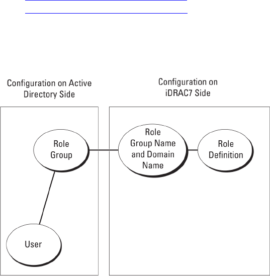
3. Right-click Certificates, select All Tasks and click Import.
4. Click Next and browse to the SSL certificate file.
5. Install iDRAC7 SSL Certificate in each domain controller’s Trusted Root Certification Authority.
If you have installed your own certificate, make sure that the CA signing your certificate is in the Trusted Root
Certification Authority list. If the Authority is not in the list, you must install it on all your domain controllers.
6. Click Next and select whether you want Windows to automatically select the certificate store based on the type of
certificate, or browse to a store of your choice.
7. Click Finish and click OK. The iDRAC7 firmware SSL certificate is imported to all domain controller trusted
certificate lists.
Supported Active Directory Authentication Mechanisms
You can use Active Directory to define iDRAC7 user access using two methods:
•
Standard schema
solution, which uses Microsoft’s default Active Directory group objects only.
•
Extended schema
solution, which has customized Active Directory objects. All the access control objects are
maintained in Active Directory. It provides maximum flexibility to configure user access on different iDRAC7s with
varying privilege levels.
Related Links
Standard Schema Active Directory Overview
Extended Schema Active Directory Overview
Standard Schema Active Directory Overview
As shown in the following figure, using standard schema for Active Directory integration requires configuration on both
Active Directory and iDRAC7.
Figure 1. Configuration of iDRAC7 with Active Directory Standard Schema
In Active Directory, a standard group object is used as a role group. A user who has iDRAC7 access is a member of the
role group. To give this user access to a specific iDRAC7, the role group name and its domain name need to be
configured on the specific iDRAC7. The role and the privilege level is defined on each iDRAC7and not in the Active
Directory. You can configure up to five role groups in each iDRAC7. Table reference no shows the default role group
privileges.
129

Table 15. Default Role Group Privileges
Role Groups Default Privilege Level Permissions Granted Bit Mask
Role Group 1 None Login to iDRAC, Configure
iDRAC, Configure Users,
Clear Logs, Execute Server
Control Commands, Access
Virtual Console, Access
Virtual Media, Test Alerts,
Execute Diagnostic
Commands
0x000001ff
Role Group 2 None Login to iDRAC, Configure
iDRAC, Execute Server
Control Commands, Access
Virtual Console, Access
Virtual Media, Test Alerts,
Execute Diagnostic
Commands
0x000000f9
Role Group 3 None Login to iDRAC 0x00000001
Role Group 4 None No assigned permissions 0x00000000
Role Group 5 None No assigned permissions 0x00000000
NOTE: The Bit Mask values are used only when setting Standard Schema with the RACADM.
Single Domain Versus Multiple Domain Scenarios
If all the login users and role groups, including the nested groups, are in the same domain, then only the domain
controllers’ addresses must be configured on iDRAC7. In this single domain scenario, any group type is supported.
If all the login users and role groups, or any of the nested groups, are from multiple domains, then Global Catalog server
addresses must be configured on iDRAC7. In this multiple domain scenario, all the role groups and nested groups, if any,
must be a Universal Group type.
Configuring Standard Schema Active Directory
To configure iDRAC7 for a Active Directory login access:
1. On an Active Directory server (domain controller), open the Active Directory Users and Computers Snap-in.
2. Create a group or select an existing group. Add the Active Directory user as a member of the Active Directory
group to access iDRAC7.
3. Configure the group name, domain name, and the role privileges on iDRAC7 using the iDRAC7 Web interface or
RACADM.
Related Links
Configuring Active Directory With Standard Schema Using iDRAC7 Web Interface
Configuring Active Directory With Standard Schema Using RACADM
130

Configuring Active Directory With Standard Schema Using iDRAC7 Web Interface
NOTE: For information about the various fields, see the
iDRAC7 Online Help
.
1. In the iDRAC7 Web interface, go to Overview → iDRAC Settings → User Authentication → Directory Services →
Microsoft Active Directory.
The Active Directory summary page is displayed.
2. Click Configure Active Directory.
The Active Directory Configuration and Management Step 1 of 4 page is displayed.
3. Optionally, enable certificate validation and upload the CA-signed digital certificate used during initiation of SSL
connections when communicating with the Active Directory (AD) server. For this, the Domain Controllers and
Global Catalog FQDN must be specified. This is done in the next steps. And hence the DNS should be configured
properly in the network settings.
4. Click Next.
The Active Directory Configuration and Management Step 2 of 4 page is displayed.
5. Enable Active Directory and specify the location information about Active Directory servers and user accounts.
Also, specify the time iDRAC7 must wait for responses from Active Directory during iDRAC7 login.
NOTE: If certificate validation is enabled, specify the Domain Controller Server addresses and the Global
Catalog FQDN. Make sure that DNS is configured correctly under Overview → iDRAC Settings → Network.
6. Click Next. The Active Directory Configuration and Management Step 3 of 4 page is displayed.
7. Select Standard Schema and click Next.
The Active Directory Configuration and Management Step 4a of 4 page is displayed.
8. Enter the location of Active Directory global catalog server(s) and specify privilege groups used to authorize users.
9. Click a Role Group to configure the control authorization policy for users under the standard schema mode.
The Active Directory Configuration and Management Step 4b of 4 page is displayed.
10. Specify the privileges and click Apply.
The settings are applied and the Active Directory Configuration and Management Step 4a of 4 page is displayed.
11. Click Finish. The Active Directory settings for standard schema is configured.
131

Configuring Active Directory With Standard Schema Using RACADM
To configure iDRAC7 Active Directory with Standard Schema using the RACADM:
1. At the racadm command prompt, run the following commands:
– Using config command:
racadm config -g cfgActiveDirectory -o cfgADEnable 1
racadm config -g cfgActiveDirectory -o cfgADType 2
racadm config -g cfgStandardSchema -i <index> -o cfgSSADRoleGroupName
<common name of the role group>
racadm config -g cfgStandardSchema -i <index> -o cfgSSADRoleGroupDomain
<fully qualified domain name>
racadm config -g cfgStandardSchema -i <index> -o
cfgSSADRoleGroupPrivilege <Bit Mask Value for specific RoleGroup
permissions>
racadm config -g cfgActiveDirectory -o cfgADDomainController1 <fully
qualified domain name or IP address of the domain controller>
racadm config -g cfgActiveDirectory -o cfgADDomainController2 <fully
qualified domain name or IP address of the domain controller>
racadm config -g cfgActiveDirectory -o cfgADDomainController3 <fully
qualified domain name or IP address of the domain controller>
racadm config -g cfgActiveDirectory -o cfgADGlobalCatalog1 <fully
qualified domain name or IP address of the domain controller>
racadm config -g cfgActiveDirectory -o cfgADGlobalCatalog2 <fully
qualified domain name or IP address of the domain controller>
racadm config -g cfgActiveDirectory -o cfgADGlobalCatalog3 <fully
qualified domain name or IP address of the domain controller>
– Using set command:
racadm set iDRAC.ActiveDirectory.Enable 1
racadm set iDRAC.ActiveDirectory.Schema 2
racadm set iDRAC.ADGroup.Name <common name of the role group>
racadm set iDRAC.ADGroup.Domain <fully qualified domain name>
racadm set iDRAC.ADGroup.Privilege <Bit Mask Value for specific RoleGroup
permissions>
racadm set iDRAC.ActiveDirectory.DomainController1 <fully qualified
domain name or IP address of the domain controller>
racadm set iDRAC.ActiveDirectory.DomainController2 <fully qualified
domain name or IP address of the domain controller>
racadm set iDRAC.ActiveDirectory.DomainController3 <fully qualified
domain name or IP address of the domain controller>
racadm set iDRAC.ActiveDirectory.GlobalCatalog1 <fully qualified domain
name or IP address of the domain controller>
racadm set iDRAC.ActiveDirectory.GlobalCatalog2 <fully qualified domain
name or IP address of the domain controller>
racadm set iDRAC.ActiveDirectory.GlobalCatalog3 <fully qualified domain
name or IP address of the domain controller>
For Bit Mask values for specific Role Group permissions, see Default Role Group Privileges.
Enter the FQDN of the domain controller, not the FQDN of the domain. For example, enter
servername.dell.com instead of dell.com.
At least one of the three addresses is required to be configured. iDRAC7 attempts to connect to each of the
configured addresses one-by-one until it makes a successful connection. With Standard Schema, these are the
addresses of the domain controllers where the user accounts and the role groups are located.
The Global Catalog server is only required for standard schema when the user accounts and role groups are in
different domains. In multiple domain case, only the Universal Group can be used.
The FQDN or IP address that you specify in this field should match the Subject or Subject Alternative Name
field of your domain controller certificate if you have certificate validation enabled.
132

If you want to disable the certificate validation during SSL handshake, enter the following RACADM command:
– Using config command: racadm config -g cfgActiveDirectory -o
cfgADCertValidationEnable 0
– Using set command: racadm set iDRAC.ActiveDirectory.CertValidationEnable 0
In this case, no Certificate Authority (CA) certificate needs to be uploaded.
To enforce the certificate validation during SSL handshake (optional):
– Using config command: racadm config -g cfgActiveDirectory -o
cfgADCertValidationEnable 1
– Using set command: racadm set iDRAC.ActiveDirectory.CertValidationEnable 1
In this case, you must upload the CA certificate using the following RACADM command:
racadm sslcertupload -t 0x2 -f <ADS root CA certificate>
NOTE: If certificate validation is enabled, specify the Domain Controller Server addresses and the Global
Catalog FQDN. Make sure that DNS is configured correctly under Overview → iDRAC Settings → Network.
Using the following RACADM command may be optional.
racadm sslcertdownload -t 0x1 -f <RAC SSL certificate>
2. If DHCP is enabled on iDRAC7 and you want to use the DNS provided by the DHCP server, enter the following
RACADM commands:
– Using config command: racadm config -g cfgLanNetworking -o cfgDNSServersFromDHCP
1
– Using set command: racadm set iDRAC.IPv4.DNSFromDHCP 1
3. If DHCP is disabled on iDRAC7 or you want manually input the DNS IP address, enter the following RACADM
commands:
– Using config command:
racadm config -g cfgLanNetworking -o cfgDNSServersFromDHCP 0
racadm config -g cfgLanNetworking -o cfgDNSServer1 <primary DNS IP
address>
racadm config -g cfgLanNetworking -o cfgDNSServer2 <secondary DNS IP
address>
– Using set command:
racadm set iDRAC.IPv4.DNSFromDHCP 0
racadm set iDRAC.IPv4.DNSFromDHCP.DNS1 <primary DNS IP address>
racadm set iDRAC.IPv4.DNSFromDHCP.DNS2 <secondary DNS IP address>
4. If you want to configure a list of user domains so that you only need to enter the user name when logging in to the
Web interface, enter the following command:
– Using config command: racadm config -g cfgUserDomain -o cfgUserDomainName <fully
qualified domain name or IP Address of the domain controller> -i <index>
– Using set command: racadm set iDRAC.UserDomain.<index>.Name <fully qualified
domain name or IP Address of the domain controller>
You can configure up to 40 user domains with index numbers between 1 and 40.
Extended Schema Active Directory Overview
Using the extended schema solution requires the Active Directory schema extension.
Active Directory Schema Extensions
The Active Directory data is a distributed database of
attributes
and
classes
. The Active Directory schema includes the
rules that determine the type of data that can be added or included in the database. The user class is one example of a
133
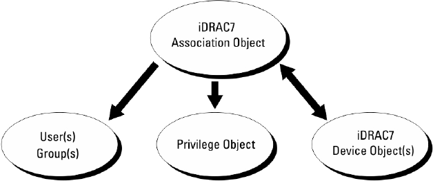
class
that is stored in the database. Some example user class attributes can include the user’s first name, last name,
phone number, and so on. You can extend the Active Directory database by adding your own unique
attributes
and
classes
for specific requirements. Dell has extended the schema to include the necessary changes to support remote
management authentication and authorization using Active Directory.
Each
attribute
or
class
that is added to an existing Active Directory Schema must be defined with a unique ID. To
maintain unique IDs across the industry, Microsoft maintains a database of Active Directory Object Identifiers (OIDs) so
that when companies add extensions to the schema, they can be guaranteed to be unique and not to conflict with each
other. To extend the schema in Microsoft's Active Directory, Dell received unique OIDs, unique name extensions, and
uniquely linked attribute IDs for the attributes and classes that are added into the directory service:
• Extension is: dell
• Base OID is: 1.2.840.113556.1.8000.1280
• RAC LinkID range is: 12070 to 12079
Overview of iDRAC7 Schema Extensions
Dell has extended the schema to include an
Association
,
Device
, and
Privilege
property. The
Association
property is
used to link together the users or groups with a specific set of privileges to one or more iDRAC7 devices. This model
provides an administrator maximum flexibility over the different combinations of users, iDRAC7 privileges, and iDRAC7
devices on the network without much complexity.
For each physical iDRAC7 device on the network that you want to integrate with Active Directory for authentication and
authorization, create at least one association object and one iDRAC7 device object. You can create multiple association
objects, and each association object can be linked to as many users, groups of users, or iDRAC7 device objects as
required. The users and iDRAC7 user groups can be members of any domain in the enterprise.
However, each association object can be linked (or, may link users, groups of users, or iDRAC7 device objects) to only
one privilege object. This example allows an administrator to control each user’s privileges on specific iDRAC7 devices.
iDRAC7 device object is the link to iDRAC7 firmware for querying Active Directory for authentication and authorization.
When iDRAC7 is added to the network, the administrator must configure iDRAC7 and its device object with its Active
Directory name so that users can perform authentication and authorization with Active Directory. Additionally, the
administrator must add iDRAC7 to at least one association object for users to authenticate.
The following figure shows that the association object provides the connection that is needed for the authentication and
authorization.
Figure 2. Typical Setup for Active Directory Objects
You can create as many or as few association objects as required. However, you must create at least one Association
Object, and you must have one iDRAC7 Device Object for each iDRAC7 device on the network that you want to integrate
with Active Directory for Authentication and Authorization with iDRAC7.
The Association Object allows for as many or as few users and/or groups as well as iDRAC7 Device Objects. However,
the Association Object only includes one Privilege Object per Association Object. The Association Object connects the
Users who have Privileges on iDRAC7 devices.
134
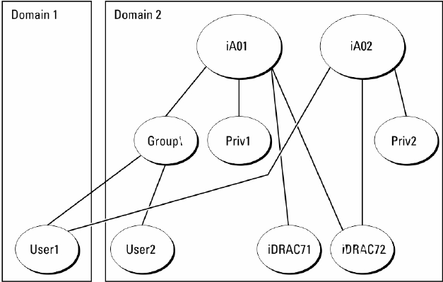
The Dell extension to the ADUC MMC Snap-in only allows associating the Privilege Object and iDRAC7 Objects from the
same domain with the Association Object. The Dell extension does not allow a group or an iDRAC7 object from other
domains to be added as a product member of the Association Object.
When adding Universal Groups from separate domains, create an Association Object with Universal Scope. The Default
Association objects created by the Dell Schema Extender Utility are Domain Local Groups and does not work with
Universal Groups from other domains.
Users, user groups, or nested user groups from any domain can be added into the Association Object. Extended Schema
solutions support any user group type and any user group nesting across multiple domains allowed by Microsoft Active
Directory.
Accumulating Privileges Using Extended Schema
The Extended Schema Authentication mechanism supports Privilege Accumulation from different privilege objects
associated with the same user through different Association Objects. In other words, Extended Schema Authentication
accumulates privileges to allow the user the super set of all assigned privileges corresponding to the different privilege
objects associated with the same user.
The following figure provides an example of accumulating privileges using Extended Schema.
Figure 3. Privilege Accumulation for a User
The figure shows two Association Objects—A01 and A02. User1 is associated to iDRAC72 through both association
objects.
Extended Schema Authentication accumulates privileges to allow the user the maximum set of privileges possible
considering the assigned privileges of the different privilege objects associated to the same user.
In this example, User1 has both Priv1 and Priv2 privileges on iDRAC72. User1 has Priv1 privileges on iDRAC71 only. User2
has Priv1 privileges on both iDRAC71 and iDRAC72. In addition, this figure shows that User1 can be in a different domain
and can be a member of a group.
Configuring Extended Schema Active Directory
To configure Active Directory to access iDRAC7:
1. Extend the Active Directory schema.
2. Extend the Active Directory Users and Computers Snap-in.
135

3. Add iDRAC7 users and their privileges to Active Directory.
4. Configure iDRAC7 Active Directory properties using iDRAC7 Web interface or RACADM.
Related Links
Extended Schema Active Directory Overview
Installing Dell Extension to the Active Directory Users and Computers Snap-In
Adding iDRAC7 Users and Privileges to Active Directory
Configuring Active Directory With Extended Schema Using iDRAC7 Web Interface
Configuring Active Directory With Extended Schema Using RACADM
Extending Active Directory Schema
Extending your Active Directory schema adds a Dell organizational unit, schema classes and attributes, and example
privileges and association objects to the Active Directory schema. Before you extend the schema, make sure that you
have Schema Admin privileges on the Schema Master Flexible Single Master Operation (FSMO) Role Owner of the
domain forest.
NOTE: Make sure to use the schema extension for this product is different from the previous generations of RAC
products. The earlier schema does not work with this product.
NOTE: Extending the new schema has no impact on previous versions of the product.
You can extend your schema using one of the following methods:
• Dell Schema Extender utility
• LDIF script file
If you use the LDIF script file, the Dell organizational unit is not added to the schema.
The LDIF files and Dell Schema Extender are located on your
Dell Systems Management Tools and Documentation
DVD
in the following respective directories:
• DVDdrive:\SYSMGMT\ManagementStation\support\OMActiveDirectory_Tools\Remote_Management_Advanced
\LDIF_Files
• <DVDdrive>:\SYSMGMT\ManagementStation\support\OMActiveDirectory_Tools\Remote_Management_Advanced
\Schema Extender
To use the LDIF files, see the instructions in the readme included in the LDIF_Files directory.
You can copy and run the Schema Extender or LDIF files from any location.
Using Dell Schema Extender
CAUTION: The Dell Schema Extender uses the SchemaExtenderOem.ini file. To make sure that the Dell Schema
Extender utility functions properly, do not modify the name of this file.
1. In the Welcome screen, click Next.
2. Read and understand the warning and click Next.
3. Select Use Current Log In Credentials or enter a user name and password with schema administrator rights.
4. Click Next to run the Dell Schema Extender.
5. Click Finish.
The schema is extended. To verify the schema extension, use the MMC and the Active Directory Schema Snap-in
to verify that the classes and attributes Classes and Attributes exist. See the Microsoft documentation for details
about using the MMC and the Active Directory Schema Snap-in.
136

Classes and Attributes
Table 16. Class Definitions for Classes Added to the Active Directory Schema
Class Name Assigned Object Identification Number (OID)
delliDRACDevice 1.2.840.113556.1.8000.1280.1.7.1.1
delliDRACAssociation 1.2.840.113556.1.8000.1280.1.7.1.2
dellRAC4Privileges 1.2.840.113556.1.8000.1280.1.1.1.3
dellPrivileges 1.2.840.113556.1.8000.1280.1.1.1.4
dellProduct 1.2.840.113556.1.8000.1280.1.1.1.5
Table 17. dellRacDevice Class
OID 1.2.840.113556.1.8000.1280.1.7.1.1
Description Represents the Dell iDRAC7 device. iDRAC7 must be
configured as delliDRACDevice in Active Directory.
This configuration enables iDRAC to send Lightweight
Directory Access Protocol (LDAP) queries to Active
Directory.
Class Type Structural Class
SuperClasses dellProduct
Attributes dellSchemaVersion
dellRacType
Table 18. delliDRACAssociationObject Class
OID 1.2.840.113556.1.8000.1280.1.7.1.2
Description Represents the Dell Association Object. The Association
Object provides the connection between the users and the
devices.
Class Type Structural Class
SuperClasses Group
Attributes dellProductMembers
dellPrivilegeMember
Table 19. dellRAC4Privileges Class
OID 1.2.840.113556.1.8000.1280.1.1.1.3
Description Defines the privileges (Authorization Rights) for iDRAC7
Class Type Auxiliary Class
SuperClasses None
Attributes dellIsLoginUser
dellIsCardConfigAdmin
dellIsUserConfigAdmin
dellIsLogClearAdmin
dellIsServerResetUser
dellIsConsoleRedirectUser
137

OID 1.2.840.113556.1.8000.1280.1.1.1.3
dellIsVirtualMediaUser
dellIsTestAlertUser
dellIsDebugCommandAdmin
Table 20. dellPrivileges Class
OID 1.2.840.113556.1.8000.1280.1.1.1.4
Description Used as a container Class for the Dell Privileges
(Authorization Rights).
Class Type Structural Class
SuperClasses User
Attributes dellRAC4Privileges
Table 21. dellProduct Class
OID 1.2.840.113556.1.8000.1280.1.1.1.5
Description The main class from which all Dell products are derived.
Class Type Structural Class
SuperClasses Computer
Attributes dellAssociationMembers
Table 22. List of Attributes Added to the Active Directory Schema
Attribute Name/Description Assigned OID/Syntax Object Identifier Single Valued
dellPrivilegeMember
List of dellPrivilege Objects that
belong to this Attribute.
1.2.840.113556.1.8000.1280.1.1.2.1
Distinguished Name (LDAPTYPE_DN
1.3.6.1.4.1.1466.115.121.1.12)
FALSE
dellProductMembers
List of dellRacDevice and
DelliDRACDevice Objects that
belong to this role. This attribute is
the forward link to the
dellAssociationMembers
backward link.
Link ID: 12070
1.2.840.113556.1.8000.1280.1.1.2.2
Distinguished Name (LDAPTYPE_DN
1.3.6.1.4.1.1466.115.121.1.12)
FALSE
dellIsLoginUser
TRUE if the user has Login rights on
the device.
1.2.840.113556.1.8000.1280.1.1.2.3
Boolean (LDAPTYPE_BOOLEAN
1.3.6.1.4.1.1466.115.121.1.7)
TRUE
dellIsCardConfigAdmin
TRUE if the user has Card
Configuration rights on the device.
1.2.840.113556.1.8000.1280.1.1.2.4
Boolean (LDAPTYPE_BOOLEAN
1.3.6.1.4.1.1466.115.121.1.7)
TRUE
dellIsUserConfigAdmin
TRUE if the user has User
Configuration rights on the device.
1.2.840.113556.1.8000.1280.1.1.2.5
Boolean (LDAPTYPE_BOOLEAN
1.3.6.1.4.1.1466.115.121.1.7)
TRUE
delIsLogClearAdmin 1.2.840.113556.1.8000.1280.1.1.2.6 TRUE
138

Attribute Name/Description Assigned OID/Syntax Object Identifier Single Valued
TRUE if the user has Log Clearing
rights on the device.
Boolean (LDAPTYPE_BOOLEAN
1.3.6.1.4.1.1466.115.121.1.7)
dellIsServerResetUser
TRUE if the user has Server Reset
rights on the device.
1.2.840.113556.1.8000.1280.1.1.2.7
Boolean (LDAPTYPE_BOOLEAN
1.3.6.1.4.1.1466.115.121.1.7)
TRUE
dellIsConsoleRedirectUser
TRUE if the user has Virtual
Console rights on the device.
1.2.840.113556.1.8000.1280.1.1.2.8
Boolean (LDAPTYPE_BOOLEAN
1.3.6.1.4.1.1466.115.121.1.7)
TRUE
dellIsVirtualMediaUser
TRUE if the user has Virtual Media
rights on the device.
1.2.840.113556.1.8000.1280.1.1.2.9
Boolean (LDAPTYPE_BOOLEAN
1.3.6.1.4.1.1466.115.121.1.7)
TRUE
dellIsTestAlertUser
TRUE if the user has Test Alert User
rights on the device.
1.2.840.113556.1.8000.1280.1.1.2.10
Boolean (LDAPTYPE_BOOLEAN
1.3.6.1.4.1.1466.115.121.1.7)
TRUE
dellIsDebugCommandAdmin
TRUE if the user has Debug
Command Admin rights on
the device.
1.2.840.113556.1.8000.1280.1.1.2.11
Boolean (LDAPTYPE_BOOLEAN
1.3.6.1.4.1.1466.115.121.1.7)
TRUE
dellSchemaVersion
The Current Schema Version is
used to update the schema.
1.2.840.113556.1.8000.1280.1.1.2.12
Case Ignore String
(LDAPTYPE_CASEIGNORESTRING
1.2.840.113556.1.4.905)
TRUE
dellRacType
This attribute is the Current RAC
Type for the delliDRACDevice
object and the backward link to the
dellAssociationObjectMembers
forward link.
1.2.840.113556.1.8000.1280.1.1.2.13
Case Ignore String
(LDAPTYPE_CASEIGNORESTRING
1.2.840.113556.1.4.905)
TRUE
dellAssociationMembers
List of
dellAssociationObjectMembers
that belong to this Product. This
attribute is the backward link to the
dellProductMembers linked
attribute.
Link ID: 12071
1.2.840.113556.1.8000.1280.1.1.2.14
Distinguished Name (LDAPTYPE_DN
1.3.6.1.4.1.1466.115.121.1.12)
FALSE
Installing Dell Extension to the Active Directory Users and Computers Snap-In
When you extend the schema in Active Directory, you must also extend the Active Directory Users and Computers Snap-
in so the administrator can manage iDRAC7 devices, users and user groups, iDRAC7 associations, and iDRAC7
privileges.
When you install your systems management software using the
Dell Systems Management Tools and Documentation
DVD, you can extend the Snap-in by selecting the Active Directory Users and Computers Snap-in option during the
installation procedure. See the Dell OpenManage Software Quick Installation Guide for additional instructions about
installing systems management software. For 64-bit Windows Operating Systems, the Snap-in installer is located under:
<DVDdrive>:\SYSMGMT\ManagementStation\support\OMActiveDirectory_SnapIn64
For more information about the Active Directory Users and Computers Snap-in, see Microsoft documentation.
139

Adding iDRAC7 Users and Privileges to Active Directory
Using the Dell-extended Active Directory Users and Computers Snap-in, you can add iDRAC7 users and privileges by
creating device, association, and privilege objects. To add each object, perform the following:
• Create an iDRAC7 device Object
• Create a Privilege Object
• Create an Association Object
• Add objects to an Association Object
Related Links
Adding Objects to Association Object
Creating iDRAC7 Device Object
Creating Privilege Object
Creating Association Object
Creating iDRAC7 Device Object
To create iDRAC7 device object:
1. In the MMC Console Root window, right-click a container.
2. Select New → Dell Remote Management Object Advanced.
The New Object window is displayed.
3. Enter a name for the new object. The name must be identical to iDRAC7 name that you enter while configuring
Active Directory properties using iDRAC7 Web interface.
4. Select iDRAC Device Object and click OK.
Creating Privilege Object
To create prvivlege object:
NOTE: You must create a privilege object in the same domain as the related association object.
1. In the Console Root (MMC) window, right-click a container.
2. Select New → Dell Remote Management Object Advanced.
The New Object window is displayed.
3. Enter a name for the new object.
4. Select Privilege Object and click OK.
5. Right-click the privilege object that you created, and select Properties.
6. Click the Remote Management Privileges tab and assign the privileges for the user or group.
Creating Association Object
To create association object:
NOTE: iDRAC7 association object is derived from the group and its scope is set to Domain Local.
1. In the Console Root (MMC) window, right-click a container.
2. Select New → Dell Remote Management Object Advanced.
This New Object window is displayed.
3. Enter a name for the new object and select Association Object.
4. Select the scope for the Association Object and click OK.
140

5. Provide access privileges to the authenticated users for accessing the created association objects.
Related Links
Providing User Access Privileges For Association Objects
Providing User Access Privileges For Association Objects
To provide access privileges to the authenticated users for accessing the created association objects:
1. Go to Administrative Tools → ADSI Edit. The ADSI Edit window is displayed.
2. In the right-pane, navigate to the created association object, right-click and select Properties.
3. In the Security tab, click Add.
4. Type Authenticated Users, click Check Names, and click OK. The authenticated users is added to the list of
Groups and user names.
5. Click OK.
Adding Objects to Association Object
Using the Association Object Properties window, you can associate users or user groups, privilege objects, and iDRAC7
devices or iDRAC7 device groups.
You can add groups of users and iDRAC7 devices.
Related Links
Adding Users or User Groups
Adding Privileges
Adding iDRAC7 Devices or iDRAC7 Device Groups
Adding Users or User Groups
To add users or user groups:
1. Right-click the Association Object and select Properties.
2. Select the Users tab and click Add.
3. Enter the user or user group name and click OK.
Adding Privileges
To add privileges:
Click the Privilege Object tab to add the privilege object to the association that defines the user’s or user group’s
privileges when authenticating to an iDRAC7 device. Only one privilege object can be added to an Association Object.
1. Select the Privileges Object tab and click Add.
2. Enter the privilege object name and click OK.
3. Click the Privilege Object tab to add the privilege object to the association that defines the user’s or user group’s
privileges when authenticating to an iDRAC7 device. Only one privilege object can be added to an Association
Object.
Adding iDRAC7 Devices or iDRAC7 Device Groups
To add iDRAC7 devices or iDRAC7 device groups:
1. Select the Products tab and click Add.
2. Enter iDRAC7 devices or iDRAC7 device group name and click OK.
3. In the Properties window, click Apply and click OK.
4. Click the Products tab to add one iDRAC7 device connected to the network that is available for the defined users or
user groups. You can add multiple iDRAC7 devices to an Association Object.
141

Configuring Active Directory With Extended Schema Using iDRAC7 Web Interface
To configure Active Directory with extended schema using Web interface:
NOTE: For information about the various fields, see the
iDRAC7 Online Help
.
1. In the iDRAC7 Web interface, go to Overview → iDRAC Settings → User Authentication → Directory Services →
Microsoft Active Directory.
The Active Directory summary page is displayed.
2. Click Configure Active Directory.
The Active Directory Configuration and Management Step 1 of 4 page is displayed.
3. Optionally, enable certificate validation and upload the CA-signed digital certificate used during initiation of SSL
connections when communicating with the Active Directory (AD) server.
4. Click Next.
The Active Directory Configuration and Management Step 2 of 4 page is displayed.
5. Specify the location information about Active Directory (AD) servers and user accounts. Also, specify the time
iDRAC7 must wait for responses from AD during login process.
NOTE: If certificate validation is enabled, specify the Domain Controller Server addresses and the FQDN.
Make sure that DNS is configured correctly under Overview → iDRAC Settings → Network.
6. Click Next. The Active Directory Configuration and Management Step 3 of 4 page is displayed.
7. Select Extended Schema and click Next.
The Active Directory Configuration and Management Step 4 of 4 page is displayed.
8. Enter the name and location of the iDRAC7 device object in Active Directory (AD) and click Finish.
The Active Directory settings for extended schema mode is configured.
142

Configuring Active Directory With Extended Schema Using RACADM
To configure Active Directory with Extended Schema using the RACADM:
1. Open a command prompt and enter the following RACADM commands:
– Using config command:
racadm config -g cfgActiveDirectory -o cfgADEnable 1
racadm config -g cfgActiveDirectory -o cfgADType 1
racadm config -g cfgActiveDirectory -o cfgADRacName <RAC common name>
racadm config -g cfgActiveDirectory -o cfgADRacDomain <fully qualified
rac domain name>
racadm config -g cfgActiveDirectory -o cfgADDomainController1 <fully
qualified domain name or IP Address of the domain controller>
racadm config -g cfgActiveDirectory -o cfgADDomainController2 <fully
qualified domain name or IP Address of the domain controller>
racadm config -g cfgActiveDirectory -o cfgADDomainController3 <fully
qualified domain name or IP Address of the domain controller>
– Using set command:
racadm set iDRAC.ActiveDirectory.Enable 1
racadm set iDRAC.ActiveDirectory.Schema 2
racadm set iDRAC.ActiveDirectory.RacName <RAC common name>
racadm set iDRAC.ActiveDirectory.RacDomain <fully qualified rac domain
name>
racadm set iDRAC.ActiveDirectory.DomainController1 <fully qualified
domain name or IP address of the domain controller>
racadm set iDRAC.ActiveDirectory.DomainController2 <fully qualified
domain name or IP address of the domain controller>
racadm set iDRAC.ActiveDirectory.DomainController3 <fully qualified
domain name or IP address of the domain controller>
NOTE: You must configure at least one of the three addresses. iDRAC7 attempts to connect to each of the
configured addresses one-by-one until it makes a successful connection. With Extended Schema, these are
the FQDN or IP addresses of the domain controllers where this iDRAC7 device is located.
To disable the certificate validation during SSL handshake (optional):
– Using config command: racadm config -g cfgActiveDirectory -o
cfgADCertValidationEnable 0
– Using set command: racadm set iDRAC.ActiveDirectory.CertValidationEnable 0
NOTE: In this case, you do not have to upload a CA certificate.
To enforce the certificate validation during SSL handshake (optional):
– Using config command: racadm config -g cfgActiveDirectory -o
cfgADCertValidationEnable 1
– Using set command: racadm set iDRAC.ActiveDirectory.CertValidationEnable 1
In this case, you must upload a CA certificate:
racadm sslcertupload -t 0x2 -f <ADS root CA certificate>
NOTE: If certificate validation is enabled, specify the Domain Controller Server addresses and the FQDN.
Make sure that DNS is configured correctly under Overview → iDRAC Settings → Network.
Using the following RACADM command may be optional:
racadm sslcertdownload -t 0x1 -f <RAC SSL certificate>
2. If DHCP is enabled on iDRAC7 and you want to use the DNS provided by the DHCP server, enter the following
RACADM command:
143

– Using config command: racadm config -g cfgLanNetworking -o cfgDNSServersFromDHCP
1
– Using set command: racadm set iDRAC.IPv4.DNSFromDHCP 1
3. If DHCP is disabled in iDRAC7 or you want to manually input your DNS IP address, enter the following RACADM
commands:
– Using config command:
racadm config -g cfgLanNetworking -o cfgDNSServersFromDHCP 0
racadm config -g cfgLanNetworking -o cfgDNSServer1 <primary DNS IP
address>
racadm config -g cfgLanNetworking -o cfgDNSServer2 <secondary DNS IP
address>
– Using set command:
racadm set iDRAC.IPv4.DNSFromDHCP 0
racadm set iDRAC.IPv4.DNSFromDHCP.DNS1 <primary DNS IP address>
racadm set iDRAC.IPv4.DNSFromDHCP.DNS2 <secondary DNS IP address>
4. If you want to configure a list of user domains so that you only need to enter the user name during log in to iDRAC7
Web interface, enter the following command:
– Using config command: racadm config -g cfgUserDomain -o cfgUserDomainName <fully
qualified domain name or IP Address of the domain controller> -i <index>
– Using set command: racadm set iDRAC.UserDomain.<index>.Name <fully qualified
domain name or IP Address of the domain controller>
You can configure up to 40 user domains with index numbers between 1 and 40.
5. Press Enter to complete the Active Directory configuration with Extended Schema.
Testing Active Directory Settings
You can test the Active Directory settings to verify whether your configuration is correct, or to diagnose the problem
with a failed Active Directory log in.
Testing Active Directory Settings Using iDRAC7 Web Interface
To test the Active Directory settings:
1. In iDRAC7 Web Interface, go to Overview → iDRAC Settings → User Authentication → Directory Services →
Microsoft Active Directory.
The Active Directory summary page is displayed.
2. Click Test Settings.
3. Enter a test user's name (for example, username@domain.com) and password and click Start Test. A detailed test
results and the test log displays.
If there is a failure in any step, examine the details in the test log to identify the problem and a possible solution.
NOTE: When testing Active Directory settings with Enable Certificate Validation checked, iDRAC7 requires
that the Active Directory server be identified by the FQDN and not an IP address. If the Active Directory
server is identified by an IP address, certificate validation fails because iDRAC7 is not able to communicate
with the Active Directory server.
Testing Active Directory Settings Using RACADM
To test the Active Directory settings, use the testfeature command. For more information, see the
RACADM
Command Line Reference Guide for iDRAC7 and CMC
available at dell.com/support/manuals.
144

Configuring Generic LDAP Users
iDRAC7 provides a generic solution to support Lightweight Directory Access Protocol (LDAP)-based authentication. This
feature does not require any schema extension on your directory services.
To make iDRAC7 LDAP implementation generic, the commonality between different directory services is utilized to group
users and then map the user-group relationship. The directory service specific action is the schema. For example, they
may have different attribute names for the group, user, and the link between the user and the group. These actions can
be configured in iDRAC7.
NOTE: The Smart Card based Two Factor Authentication (TFA) and the Single Sign-On (SSO) logins are not
supported for generic LDAP Directory Service.
Related Links
Configuring Generic LDAP Directory Service Using iDRAC7 Web-Based Interface
Configuring Generic LDAP Directory Service Using RACADM
Configuring Generic LDAP Directory Service Using iDRAC7 Web-Based Interface
To configure the generic LDAP directory service using Web interface:
NOTE: For information about the various fields, see the
iDRAC7 Online Help
.
1. In the iDRAC7 Web interface, go to Overview → iDRAC Settings → User Authentication → Directory Services →
Generic LDAP Directory Service.
The Generic LDAP Configuration and Management page displays the current generic LDAP settings.
2. Click Configure Generic LDAP.
3. Optionally, enable certificate validation and upload the digital certificate used during initiation of SSL connections
when communicating with a generic LDAP server.
NOTE: In this release, non-SSL port based LDAP bind is not supported. Only LDAP over SSL is supported.
4. Click Next.
The Generic LDAP Configuration and Management Step 2 of 3 page is displayed.
5. Enable generic LDAP authentication and specify the location information about generic LDAP servers and user
accounts.
NOTE: If certificate validation is enabled, specify the LDAP Server’s FQDN and make sure that DNS is
configured correctly under Overview → iDRAC Settings → Network .
NOTE: In this release, nested group is not supported. The firmware searches for the direct member of the
group to match the user DN. Also, only single domain is supported. Cross domain is not supported.
6. Click Next.
The Generic LDAP Configuration and Management Step 3a of 3 page is displayed.
7. Click Role Group.
The Generic LDAP Configuration and Management Step 3b of 3 page is displayed.
8. Specify the group distinguished name, the privileges associated with the group, and click Apply.
NOTE: If you are using Novell eDirectory and if you have used these characters—#(hash), "(double quotes), ;
(semi colon), > (greater than), , (comma), or <(lesser than)—for the Group DN name, they must be escaped.
The role group settings are saved. The Generic LDAP Configuration and Management Step 3a of 3 page displays
the role group settings.
145

9. If you want to configure additional role groups, repeat steps 7 and 8.
10. Click Finish. The generic LDAP directory service is configured.
Configuring Generic LDAP Directory Service Using RACADM
To configure the LDAP directory service:
• Use the objects in the cfgLdap and cfgLdapRoleGroup groups with the config command.
• Use the objects in the iDRAC.LDAP and iDRAC.LDAPRole groups with the set command.
For more information, see the
RACADM Command Line Reference Guide for iDRAC7 and CMC
available at dell.com/
support/manuals.
Testing LDAP Directory Service Settings
You can test the LDAP directory service settings to verify whether your configuration is correct, or to diagnose the
problem with a failed LDAP log in.
Testing LDAP Directory Service Settings Using iDRAC7 Web Interface
To test the LDAP directory service settings:
1. In iDRAC7 Web Interface, go to Overview → iDRAC Settings → User Authentication → Directory Services →
Generic LDAP Directory Service.
The Generic LDAP Configuration and Management page displays the current generic LDAP settings.
2. Click Test Settings.
3. Enter the user name and password of a directory user that is chosen to test the LDAP settings. The format depends
on the
Attribute of User Login
is used and the user name entered must match the value of the chosen attribute.
NOTE: When testing LDAP settings with Enable Certificate Validation checked, iDRAC7 requires that the
LDAP server be identified by the FQDN and not an IP address. If the LDAP server is identified by an IP
address, certificate validation fails because iDRAC7 is not able to communicate with the LDAP server.
NOTE: When generic LDAP is enabled, iDRAC7 first tries to login the user as a directory user. If it fails, local
user lookup is enabled.
The test results and the test log are displayed.
Testing LDAP Directory Service Settings Using RACADM
To test the LDAP directory service settings, use the testfeature command. For more information, see the
RACADM
Command Line Reference Guide for iDRAC7 and CMC
available at dell.com/support/manuals.
146

8
Configuring iDRAC7 for Single Sign-On or Smart
Card Login
This section provides information to configure iDRAC7 for Smart Card login (for local users and Active Directory users),
and Single Sign-On (SSO) login (for Active Directory users.) SSO and smart card login are licensed features.
iDRAC7 supports Kerberos based Active Directory authentication to support Smart Card and SSO logins. For information
on Kerberos, see the Microsoft website.
Related Links
Configuring iDRAC7 SSO Login for Active Directory Users
Configuring iDRAC7 Smart Card Login for Local Users
Configuring iDRAC7 Smart Card Login for Active Directory Users
Prerequisites for Active Directory Single Sign-On or Smart Card
Login
The pre-requisites to Active Directory based SSO or Smart Card logins are:
• Synchronize iDRAC7 time with the Active Directory domain controller time. If not, kerberos authentication on iDRAC7
fails. You can use the Time zone and NTP feature to synchronize the time. To do this, see Configuring Time zone and
NTP.
• Register iDRAC7 as a computer in the Active Directory root domain.
• Generate a keytab file using the ktpass tool.
• To enable single sign-on for Extended schema, make sure that the Trust this user for delegation to any service
(Kerberos only) option is selected on the Delegation tab for the keytab user. This tab is available only after creating
the keytab file using ktpass utility.
• Configure the browser to enable SSO login.
• Create the Active Directory objects and provide the required privileges.
• For SSO, configure the reverse lookup zone on the DNS servers for the subnet where iDRAC7 resides.
NOTE: If the host name does not match the reverse DNS lookup, Kerberos authentication fails.
Related Links
Configuring Browser to Enable Active Directory SSO
Registering iDRAC7 as a Computer in Active Directory Root Domain
Generating Kerberos Keytab File
Creating Active Directory Objects and Providing Privileges
147

Registering iDRAC7 as a Computer in Active Directory Root Domain
To register iDRAC7 in Active Directory root domain:
1. Click Overview → iDRAC Settings → Network → Network.
The Network page is displayed.
2. Provide a valid Preferred/Alternate DNS Server IP address. This value is a valid DNS server IP address that is part
of the root domain.
3. Select Register iDRAC on DNS.
4. Provide a valid DNS Domain Name.
5. Verify that network DNS configuration matches with the Active Directory DNS information.
For more information about the options, see the
iDRAC7 Online Help
.
Generating Kerberos Keytab File
To support the SSO and smart card login authentication, iDRAC7 supports the configuration to enable itself as a
kerberized service on a Windows Kerberos network. The Kerberos configuration on iDRAC7 involves the same steps as
configuring a non–Windows Server Kerberos service as a security principal in Windows Server Active Directory.
The
ktpass
tool (available from Microsoft as part of the server installation CD/DVD) is used to create the Service
Principal Name (SPN) bindings to a user account and export the trust information into a MIT–style Kerberos
keytab
file,
which enables a trust relation between an external user or system and the Key Distribution Centre (KDC). The keytab file
contains a cryptographic key, which is used to encrypt the information between the server and the KDC. The ktpass tool
allows UNIX–based services that support Kerberos authentication to use the interoperability features provided by a
Windows Server Kerberos KDC service. For more information on the ktpass utility, see the Microsoft website at:
technet.microsoft.com/en-us/library/cc779157(WS.10).aspx
Before generating a keytab file, you must create an Active Directory user account for use with the -mapuser option of
the ktpass command. Also, you must have the same name as iDRAC7 DNS name to which you upload the generated
keytab file.
To generate a keytab file using the ktpass tool:
1. Run the
ktpass
utility on the domain controller (Active Directory server) where you want to map iDRAC7 to a user
account in Active Directory.
2. Use the following ktpass command to create the Kerberos keytab file:
C:\> ktpass.exe -princ HTTP/idrac7name.domainname.com@DOMAINNAME.COM -
mapuser DOMAINNAME\username -mapOp set -crypto AES256-SHA1 -ptype
KRB5_NT_PRINCIPAL -pass [password] -out c:\krbkeytab
The encryption type is AES256-SHA1 . The principal type is KRB5_NT_PRINCIPAL. The properties of the user
account that the Service Principal Name is mapped to should have Use AES 256 encryption types for this account
property enabled.
NOTE: Use lowercase letters for the iDRAC7name and Service Principal Name. Use uppercase letters for the
domain name as shown in the example.
148

3. Run the following command:
C:\>setspn -a HTTP/iDRAC7name.domainname.com username
A keytab file is generated.
NOTE: If you find any issues with iDRAC7 user for which the keytab file is created, create a new user and a
new keytab file. If the same keytab file which was initially created is again executed, it does not configure
correctly.
Creating Active Directory Objects and Providing Privileges
Perform the following steps for Active Directory Extended schema based SSO login:
1. Create the device object, privilege object, and association object in the Active Directory server.
2. Set access privileges to the created privilege object. It is recommended not to provide administrator privileges as
this could bypass some security checks.
3. Associate the device object and privilege object using the association object.
4. Add the preceding SSO user (login user) to the device object.
5. Provide access privilege to
Authenticated Users
for accessing the created association object.
Related Links
Adding iDRAC7 Users and Privileges to Active Directory
Configuring Browser to Enable Active Directory SSO
This section provides the browser settings for Internet Explorer and Firefox to enable Active Directory SSO.
NOTE: Google Chrome and Safari do not support Active Directory for SSO login.
Configuring Internet Explorer to Enable Active Directory SSO
To configure the browser settings for Internet Explorer:
1. In Internet Explorer, navigate to Local Intranet and click Sites.
2. Select the following options only:
– Include all local (intranet) sites not listed on other zones.
– Include all sites that bypass the proxy server.
3. Click Advanced.
4. Add all relative domain names that will be used for iDRAC7 instances that is part of the SSO configuration (for
example, myhost.example.com.)
5. Click Close and click OK twice.
Configuring Firefox to Enable Active Directory SSO
To configure the browser settings for Firefox:
1. In Firefox address bar, enter about:config.
2. In Filter, enter network.negotiate.
3. Add the iDRAC7 name to network.negotiate-auth.trusted-uris (using comma separated list.)
4. Add the iDRAC7 name to network.negotiate-auth.delegation-uris (using comma separated list.)
149

Configuring iDRAC7 SSO Login for Active Directory Users
Before configuring iDRAC7 for Active Directory SSO login, make sure that you have completed all the prerequisites.
You can configure iDRAC7 for Active Directory SSO when you setup an user account based on Active Directory.
Related Links
Prerequisites for Active Directory Single Sign-On or Smart Card Login
Configuring Active Directory With Standard Schema Using iDRAC7 Web Interface
Configuring Active Directory With Standard Schema Using RACADM
Configuring Active Directory With Extended Schema Using iDRAC7 Web Interface
Configuring Active Directory With Extended Schema Using RACADM
Configuring iDRAC7 SSO Login for Active Directory Users Using Web Interface
To configure iDRAC7 for Active Directory SSO login:
NOTE: For information about the options, see the
iDRAC7 Online Help
.
1. Verify whether the iDRAC7 DNS name matches the iDRAC7 Fully Qualified Domain Name. To do this, in iDRAC7 Web
interface, go to Overview → iDRAC Settings → Network → Network and see the DNS Domain Name property.
2. While configuring Active Directory to setup a user account based on standard schema or extended schema,
perform the following two additional steps to configure SSO:
– Upload the keytab file on the Active Directory Configuration and Management Step 1 of 4 page.
– Select Enable Single Sign-On option on the Active Directory Configuration and Management Step 2 of 4 page.
Configuring iDRAC7 SSO Login for Active Directory Users Using RACADM
In addition to the steps performed while configuring Active Directory, to enable SSO, run any of the following command:
• Using config command:
racadm config -g cfgActiveDirectory -o cfgADSSOEnable 1
• Using set command:
racadm set iDRAC.ActiveDirectory.SSOEnable 1
Configuring iDRAC7 Smart Card Login for Local Users
To configure iDRAC7 local user for smart card login:
1. Upload the smart card user certificate and trusted CA certificate to iDRAC7.
2. Enable smart card login.
Related Links
Obtaining Certificates
Uploading Smart Card User Certificate
Enabling or Disabling Smart Card Login
150

Uploading Smart Card User Certificate
Before you upload the user certificate, make sure that the user certificate from the smart card vendor is exported in
Base64 format. SHA-2 certificates are also supported.
Related Links
Obtaining Certificates
Uploading Smart Card User Certificate Using Web Interface
To upload smart card user certificate:
1. In iDRAC7 Web interface, go to Overview → iDRAC Settings → Network → User Authentication → Local Users.
The Users page is displayed.
2. In the User ID column, click a user ID number.
The Users Main Menu page is displayed.
3. Under Smart Card Configurations, select Upload User Certificate and click Next.
The User Certificate Upload page is displayed.
4. Browse and select the Base64 user certificate, and click Apply.
Uploading Smart Card User Certificate Using RACADM
To upload smart card user certificate, use the usercertupload object. For more information, see the
RACADM Command
Line Reference Guide for iDRAC7 and CMC
available at dell.com/support/manuals.
Uploading Trusted CA Certificate For Smart Card
Before you upload the CA certificate, make sure that you have a CA-signed certificate.
Related Links
Obtaining Certificates
Uploading Trusted CA Certificate For Smart Card Using Web Interface
To upload trusted CA certificate for smart card login:
1. In iDRAC7 Web interface, go to Overview → iDRAC Settings → Network → User Authentication → Local Users.
The Users page is displayed.
2. In the User ID column, click a user ID number.
The Users Main Menu page is displayed.
3. Under Smart Card Configurations, select Upload Trusted CA Certificate and click Next.
The Trusted CA Certificate Upload page is displayed.
4. Browse and select the trusted CA certificate, and click Apply.
Uploading Trusted CA Certificate For Smart Card Using RACADM
To upload trusted CA certificate for smart card login, use the usercertupload object. For more information, see the
RACADM Command Line Reference Guide for iDRAC7 and CMC
available at dell.com/support/manuals.
Configuring iDRAC7 Smart Card Login for Active Directory Users
Before configuring iDRAC7 Smart Card login for Active Directory users, make sure that you have completed the required
prerequisites.
151

To configure iDRAC7 for smart card login:
1. In iDRAC7 Web interface, while configuring Active Directory to set up an user account based on standard schema
or extended schema, on the Active Directory Configuration and Management Step 1 of 4 page:
– Enable certificate validation.
– Upload a trusted CA-signed certificate.
– Upload the keytab file.
2. Enable smart card login. For information about the options, see the
iDRAC7 Online Help
.
Related Links
Enabling or Disabling Smart Card Login
Obtaining Certificates
Generating Kerberos Keytab File
Configuring Active Directory With Standard Schema Using iDRAC7 Web Interface
Configuring Active Directory With Standard Schema Using RACADM
Configuring Active Directory With Extended Schema Using iDRAC7 Web Interface
Configuring Active Directory With Extended Schema Using RACADM
Enabling or Disabling Smart Card Login
Before enabling or disabling smart card login for iDRAC7, make sure that:
• You have configure iDRAC7 permissions.
• iDRAC7 local user configuration or Active Directory user configuration with the appropriate certificates is complete.
NOTE: If smart card login is enabled, then SSH, Telnet, IPMI Over LAN, Serial Over LAN, and remote RACADM are
disabled. Again, if you disable smart card login, the interfaces are not enabled automatically.
Related Links
Obtaining Certificates
Configuring iDRAC7 Smart Card Login for Active Directory Users
Configuring iDRAC7 Smart Card Login for Local Users
Enabling or Disabling Smart Card Login Using Web Interface
To enable or disable the Smart Card logon feature:
1. In the iDRAC7 Web interface, go to Overview → iDRAC Settings → User Authentication → Smart Card .
The Smart Card page is displayed.
2. From the Configure Smart Card Logon drop-down menu, select Enabled to enable smart card logon or select
Enabled With Remote RACADM. Else, select Disabled.
For more information about the options, see the
iDRAC7 Online Help
.
3. Click Apply to apply the settings.
You are prompted for a Smart Card login during any subsequent logon attempts using the iDRAC7 Web interface.
Enabling or Disabling Smart Card Login Using RACADM
To enable smart card login, use one of the following:
• Use the objects in the cfgSmartCard group with the config command.
152
• Use the objects in the iDRAC.SmartCard group with the set command.
For more information, see the
RACADM Command Line Reference Guide for iDRAC7 and CMC
available at dell.com/
support/manuals.
Enabling or Disabling Smart Card Login Using iDRAC Settings Utility
To enable or disable the Smart Card logon feature:
1. In the iDRAC Settings utility, go to Smart Card.
The iDRAC Settings Smart Card page is displayed.
2. Select Enabled to enable smart card logon. Else, select Disabled. For more information about the options, see
iDRAC Settings Utility Online Help
.
3. Click Back, click Finish, and then click Yes.
The smart card logon feature is enabled or disabled based on the selection.
153
154

9
Configuring iDRAC7 to Send Alerts
You can set alerts and actions for certain events that occur on the managed system. An event occurs when the status of
a system component is greater than the pre-defined condition. If an event matches an event filter and you have
configured this filter to generate an alert (e-mail, SNMP trap, IPMI alert, remote system logs, or WS events), then an
alert is sent to one or more configured destinations. If the same event filter is also configured to perform an action (such
as reboot, power cycle, or power off the system), the action is performed. You can set only one action for each event.
To configure iDRAC7 to send alerts:
1. Enable alerts.
2. Optionally, you can filter the alerts based on category or severity.
3. Configure the e-mail alert, IPMI alert, SNMP trap, remote system log, operating system log, and/or WS-event
settings.
4. Enable event alerts and actions such as:
– Send an email alert, IPMI alert, SNMP traps, remote system logs, operating system log, or WS events to
configured destinations.
– Perform a reboot, power off, or power cycle the managed system.
Related Links
Enabling or Disabling Alerts
Filtering Alerts
Setting Event Alerts
Setting Alert Recurrence Event
Configuring Email Alert, SNMP Trap, or IPMI Trap Settings
Configuring Remote System Logging
Configuring WS Eventing
Alerts Message IDs
Enabling or Disabling Alerts
For sending an alert to configured destinations or to perform an event action, you must enable the global alerting option.
This property overrides individual alerting or event actions that is set.
Related Links
Filtering Alerts
Configuring Email Alert, SNMP Trap, or IPMI Trap Settings
155

Enabling or Disabling Alerts Using Web Interface
To enable or disable generating alerts:
1. In iDRAC7 Web interface, go to Overview → Server → Alerts. The Alerts page is displayed.
2. Under Alerts section:
– Select Enable to enable alert generation or perform an event action.
– Select Disable to disable alert generation or disable an event action.
3. Click Apply to save the setting.
Enabling or Disabling Alerts Using RACADM
To enable or disable generating alerts or event actions using config command:
racadm config -g cfgIpmiLan -o cfgIpmiLanAlertEnable 1
To enable or disable generating alerts or event actions using set command:
racadm set iDRAC.IPMILan.AlertEnable 1
Enabling or Disabling Alerts Using iDRAC Settings Utility
To enable or disable generating alerts or event actions:
1. In the iDRAC Settings utility, go to Alerts.
The iDRAC Settings Alerts page is displayed.
2. Under Platform Events, select Enabled to enable alert generation or event action. Else, select Disabled. For more
information about the options, see
iDRAC Settings Utility Online Help.
3. Click Back, click Finish, and then click Yes.
The alert settings are configured.
Filtering Alerts
You can filter alerts based on category and severity.
Related Links
Enabling or Disabling Alerts
Configuring Email Alert, SNMP Trap, or IPMI Trap Settings
Filtering Alerts Using iDRAC7 Web Interface
To filter the alerts based on category and severity:
156

NOTE: Even if you are a user with read-only privileges, you can filter the alerts.
1. In iDRAC7 Web interface, go to Overview → Server → Alerts . The Alerts page is displayed.
2. Under Alerts Filter section, select one or more of the following categories:
– System Health
– Storage
– Configuration
– Audit
– Updates
– Work Notes
3. Select one or more of the following severity levels:
– Informational
– Warning
– Critical
4. Click Apply.
The Alert Results section displays the results based on the selected category and severity.
Filtering Alerts Using RACADM
To filter the alerts, use the eventfilters command. For more information, see the
RACADM Command Line Reference
Guide for iDRAC7 and CMC
available at dell.com/support/manuals.
Setting Event Alerts
You can set event alerts such as e-mail alerts, IPMI alerts, SNMP traps, remote system logs, operating system logs, and
WS events to be sent to configured destinations.
Related Links
Enabling or Disabling Alerts
Configuring Email Alert, SNMP Trap, or IPMI Trap Settings
Filtering Alerts
Configuring Remote System Logging
Configuring WS Eventing
Setting Event Alerts Using Web Interface
To set an event alert using the Web interface:
1. Make sure that you have configured the e-mail alert, IPMI alert, SNMP trap settings, and/or remote system log
settings.
2. Go to Overview → Server → Alerts.
The Alerts page is displayed.
157

3. Under Alerts Results, select one or all of the following alerts for the required events:
– Email Alert
– SNMP Trap
– IPMI Alert
– Remote System Log
– OS Log
– WS Eventing
4. Click Apply.
The setting is saved.
5. Under Alerts section, select the Enable option to send alerts to configured destinations.
6. Optionally, you can send a test event. In the Message ID to Test Event field, enter the message ID to test if the alert
is generated and click Test. For the list of message IDs, see the
Event Messages Guide
available at dell.com/
support/manuals.
Setting Event Alerts Using RACADM
To set an event alert, use the eventfilters command. For more information, see the
RACADM Command Line Reference
Guide for iDRAC7 and CMC
available at dell.com/support/manuals.
Setting Alert Recurrence Event
You can configure iDRAC to generate additional events at specific intervals if the system continues to operate at a
temperature which is greater than the inlet temperature threshold limit. The default interval is 30 days. The valid range is
0 to 365 days. A value of ‘0’ indicates that the event recurrence is disabled.
NOTE: You must have Configure iDRAC privilege to set the alert recurrence value.
Setting Alert Recurrence Events Using iDRAC7 Web Interface
To set the alert recurrence value:
1. In the iDRAC7 Web interface, go to Overview → Server → Alerts → Alert Recurrence.
The Alert Recurrence page is displayed.
2. In the Recurrence column, enter the alert frequency value for the required category, alert, and severity type(s).
For more information, see the
iDRAC7 Online help
.
3. Click Apply.
The alert recurrence settings are saved.
Setting Alert Recurrence Events Using RACADM
To set the alert recurrence event using RACADM, use the eventfilters subcommand. For more information, see the
RACADM Command Line Reference Guide for iDRAC7 and CMC
.
Setting Event Actions
You can set event actions such as perform a reboot, power cycle, power off, or perform no action on the system.
Related Links
Filtering Alerts
158

Enabling or Disabling Alerts
Setting Event Actions Using Web Interface
To set an event action:
1. In iDRAC7 Web interface, go to Overview → Server → Alerts . The Alerts page is displayed.
2. Under Alerts Results, from the Actions drop-down menu, for each event select an action:
– Reboot
– Power Cycle
– Power Off
– No Action
3. Click Apply.
The setting is saved.
Setting Event Actions Using RACADM
To configure an event action, use one of the following:
•eventfilters command.
•cfgIpmiPefAction object with config command.
For more information, see the
RACADM Command Line Reference Guide for iDRAC7 and CMC
available at dell.com/
support/manuals.
Configuring Email Alert, SNMP Trap, or IPMI Trap Settings
The management station uses Simple Network Management Protocol (SNMP) and Intelligent Platform Management
Interface (IPMI) traps to receive data from iDRAC7. For systems with large number of nodes, it may not be efficient for a
management station to poll each iDRAC7 for every condition that may occur. For example, event traps can help a
management station with load balancing between nodes or by issuing an alert if an authentication failure occurs.
You can configure the IPv4 and IPv6 alert destinations, email settings, and SMTP server settings, and test these settings.
Before configuring the email, SNMP, or IPMI trap settings, make sure that:
• You have Configure RAC permission.
• You have configured the event filters.
Related Links
Configuring IP Alert Destinations
Configuring Email Alert Settings
Configuring IP Alert Destinations
You can configure the IPv6 or IPv4 addresses to receive the IPMI alerts or SNMP traps.
159

Configuring IP Alert Destinations Using Web Interface
To configure alert destination settings using Web interface:
1. Go to Overview → Server → Alerts → SNMP and E-mail Settings.
2. Select the State option to enable an alert destination (IPv4 address, IPv6 address, or Fully Qualified Domain Name
(FQDN)) to receive the traps.
You can specify up to eight destination addresses. For more information about the options, see the
iDRAC7 Online
Help
.
3. Enter the iDRAC7 SNMP community string and the SNMP alert port number.
For more information about the options, see the
iDRAC7 Online Help
.
NOTE: The Community String value indicates the community string to use in a Simple Network Management
Protocol (SNMP) alert trap sent from iDRAC7. Make sure that the destination community string is the same as
the iDRAC7 community string. The default value is Public.
4. To test whether the IP address is receiving the IPMI or SNMP traps, click Send under Test IPMI Trap and Test
SNMP Trap respectively.
5. Click Apply.
The alert destinations are configured.
6. In the SNMP Trap Format section, select the protocol version to be used to send the traps on the trap destination(s)
— SNMP v1 or SNMP v2 and click Apply.
NOTE: The SNMP Trap Format option applies only for SNMP Traps and not for IPMI Traps. IPMI Traps are
always sent in SNMP v1 format and is not based on the configured SNMP Trap Format option.
The SNMP trap format is configured.
Configuring IP Alert Destinations Using RACADM
To configure the trap alert settings:
1. To enable traps:
– For IPv4 address:
racadm config -g cfgIpmiPet -o cfgIpmiPetAlertEnable -i (index) (0|1)
– For IPv6 address:
racadm config -g cfgIpmiPetIpv6 -o cfgIpmiPetIpv6AlertEnable -i (index)
(0|1)
where, (index) is the destination index and 0 or 1 disables or enables the trap, respectively.
For example, to enable trap with index 4, enter the following command:
racadm config -g cfgIpmiPet -o cfgIpmiPetAlertEnable -i 4 1
2. To configure the trap destination address:
racadm config -g cfgIpmiPetIpv6 -o cfgIpmiPetIpv6AlertDestIPAddr -i
[index] [IP-address]
where [index] is the trap destination index and [IP-address] is the destination IP address of the system
that receives the platform event alerts.
3. Configure the SNMP community name string:
racadm config -g cfgIpmiLan -o cfgIpmiPetCommunityName [name]
where [name] is the SNMP Community Name.
160

4. To test the trap, if required:
racadm testtrap -i [index]
where [index] is the trap destination index to test.
For more information, see the
RACADM Command Line Reference Guide for iDRAC7 and CMC
available at dell.com/
support/manuals.
Configuring IP Alert Destinations Using iDRAC Settings Utility
You can configure alert destinations (IPv4, IPv6, or FQDN) using the iDRAC Settings utility. To do this:
1. In the iDRAC Settings utility, go to Alerts.
The iDRAC Settings Alerts page is displayed.
2. Under Trap Settings, enable the IP address(es) to receive the traps and enter the IPv4, IPv6, or FQDN destination
address(es). You can specify up to eight addresses.
3. Enter the community string name.
For information about the options, see the
iDRAC Settings Utility Online Help
.
4. Click Back, click Finish, and then click Yes.
The alert destinations are configured.
Configuring Email Alert Settings
You can configure the email address to receive the email alerts. Also, configure the SMTP server address settings.
NOTE: If your mail server is Microsoft Exchange Server 2007, make sure that iDRAC7 domain name is configured
for the mail server to receive the email alerts from iDRAC7.
NOTE: Email alerts support both IPv4 and IPv6 addresses. The DRAC DNS Domain Name must be specified when
using IPv6.
Related Links
Configuring SMTP Email Server Address Settings
Configuring Email Alert Settings Using Web Interface
To configure the email alert settings using Web interface:
1. Go to Overview → Server → Alerts → SNMP and Email Settings .
2. Select the State option to enable the email address to receive the alerts and type a valid email address. For more
information about the options, see the
iDRAC7 Online Help.
3. Click Send under Test Email to test the configured email alert settings.
4. Click Apply.
161

Configuring Email Alert Settings Using RACADM
To configure the email alert settings:
1. To enable email alert:
– Using config command:
racadm config -g cfgEmailAlert -o cfgEmailAlertEnable -i [index] [0|1]
where [index] is the email destination index. 0 disables the email alert and 1 enables the alert.
The email destination index can be a value from 1 through 4. For example, to enable email with index 4, enter
the following command:
racadm config -g cfgEmailAlert -o cfgEmailAlertEnable -i 4 1
– Using set command:
racadm set iDRAC.EmailAlert.Enable.[index] 1
where [index] is the email destination index. 0 disables the email alert and 1 enables the alert.
The email destination index can be a value from 1 through 4. For example, to enable email with index 4, enter
the following command:
racadm set iDRAC.EmailAlert.Enable.4 1
2. To configure email settings:
– Using config command:
racadm config -g cfgEmailAlert -o cfgEmailAlertAddress -i 1 [email-
address]
where 1 is the email destination index and [email-address] is the destination email address that
receives the platform event alerts.
– Using set command:
racadm set iDRAC.EmailAlert.Address.1 [email-address]
where 1 is the email destination index and [email-address] is the destination email address that
receives the platform event alerts.
3. To configure a custom message:
– Using config command:
racadm config -g cfgEmailAlert -o cfgEmailAlertCustomMsg -i [index]
[custom-message]
where [index] is the email destination index and [custom-message] is the custom message.
– Using set command:
racadm set iDRAC.EmailAlert.CustomMsg.[index] [custom-message]
where [index] is the email destination index and[custom-message] is the custom message.
4. To test the configured email alert, if required:
racadm testemail -i [index]
where [index] is the email destination index to test.
For more information, see the
RACADM Command Line Reference Guide for iDRAC7 and CMC
available at dell.com/
support/manuals.
Configuring SMTP Email Server Address Settings
You must configure the SMTP server address for email alerts to be sent to specified destinations.
162

Configuring SMTP Email Server Address Settings Using iDRAC7 Web Interface
To configure the SMTP server address:
1. In iDRAC7 Web interface, go to Overview → Server → Alerts → SNMP and E-mail Settings.
2. Enter the valid IP address or fully qualified domain name (FQDN) of the SMTP server to be used in the configuration.
3. Select the Enable Authentication option and then provide the user name and password (of a user who has access
to SMTP server).
4. Enter the SMTP port number.
For more information about the fields, see the
iDRAC7 Online Help
.
5. Click Apply.
The SMTP settings are configured.
Configuring SMTP Email Server Address Settings Using RACADM
To configure the SMTP email server, use one of the following:
• Using set command:
racadm set iDRAC.RemoteHosts.SMTPServerIPAddress <SMTP E-mail Server IP
Address>
• Using config command:
racadm config -g cfgRemoteHosts -o cfgRhostsSmtpServerIpAddr <SMTP E-mail
Server IP Address>
Configuring WS Eventing
The WS Eventing protocol is used for a client service (subscriber) to register interest (subscription) with a server (event
source) for receiving messages containing the server events (notifications or event messages). Clients interested in
receiving the WS Eventing messages can subscribe with iDRAC and receive Lifecycle Controller job related events.
The steps required to configure WS eventing feature to receive WS Eventing messages for changes related to Lifecycle
Controller jobs are described in the Web service Eventing Support for iDRAC7 1.30.30 specification document. In addition
to this specification, see the DSP0226 (DMTF WS Management Specification), Section 10 Notifications (Eventing)
document for the complete information on the WS Eventing protocol. The Lifecycle Controller related jobs are described
in the DCIM Job Control Profile document.
Alerts Message IDs
The following table provides the list of message IDs that are displayed for the alerts.
Table 23. Alert Message IDs
Message ID Description
AMP Amperage
ASR Auto Sys Reset
BAR Backup/Restore
BAT Battery Event
BIOS BIOS Management
BOOT BOOT Control
CBL Cable
163

Message ID Description
CPU Processor
CPUA Proc Absent
CTL Storage Contr
DH Cert Mgmt
DIS Auto-Discovery
ENC Storage Enclosr
FAN Fan Event
FSD Debug
HWC Hardware Config
IPA DRAC IP Change
ITR Intrusion
JCP Job Control
LC Lifecycle Contr
LIC Licensing
LNK Link Status
LOG Log event
MEM Memory
NDR NIC OS Driver
NIC NIC Config
OSD OS Deployment
OSE OS Event
PCI PCI Device
PDR Physical Disk
PR Part Exchange
PST BIOS POST
PSU Power Supply
PSUA PSU Absent
PWR Power Usage
RAC RAC Event
RDU Redundancy
RED FW Download
RFL IDSDM Media
RFLA IDSDM Absent
RFM FlexAddress SD
RRDU IDSDM Redundancy
RSI Remote Service
SEC Security Event
164

Message ID Description
SEL Sys Event Log
SRD Software RAID
SSD PCIe SSD
STOR Storage
SUP FW Update Job
SWC Software Config
SWU Software Change
SYS System Info
TMP Temperature
TST Test Alert
UEFI UEFI Event
USR User Tracking
VDR Virtual Disk
VF vFlash SD card
VFL vFlash Event
VFLA vFlash Absent
VLT Voltage
VME Virtual Media
VRM Virtual Console
WRK Work Note
165
166

10
Managing Logs
iDRAC7 provides Lifecycle log that contains events related to system, storage devices, network devices, firmware
updates, configuration changes, license messages, and so on. However, the system events are also available as a
separate log called System Event Log (SEL). The lifecycle log is accessible through iDRAC7 Web interface, RACADM,
and WS-MAN interface.
When the size of the lifecycle log reaches 800 KB, the logs are compressed and archived. You can only view the non-
archived log entries, and apply filters and comments to non-archived logs. To view the archived logs, you must export
the entire lifecycle log to a location on your system.
Related Links
Viewing System Event Log
Viewing Lifecycle Log
Adding Work Notes
Configuring Remote System Logging
Viewing System Event Log
When a system event occurs on a managed system, it is recorded in the System Event Log (SEL). The same SEL entry is
also available in the LC log.
Viewing System Event Log Using Web Interface
To view the SEL, in iDRAC7 Web interface, go to Overview → Server → Logs.
The System Event Log page displays a system health indicator, a time stamp, and a description for each event logged.
For more information, see the
iDRAC7 Online Help
.
Click Save As to save the SEL to a location of your choice.
NOTE: If you are using Internet Explorer and if there is a problem when saving, download the Cumulative Security
Update for Internet Explorer. You can download it from the Microsoft Support website at support.microsoft.com.
To clear the logs, click Clear Log.
NOTE: Clear Log only appears if you have Clear Logs permission.
After the SEL is cleared, an entry is logged in the Lifecycle Controller log. The log entry includes the user name and the
IP address from where the SEL was cleared.
Viewing System Event Log Using RACADM
To view the SEL:
racadm getsel <options>
If no arguments are specified, the entire log is displayed.
To display the number of SEL entries: racadm getsel -i
To clear the SEL entries: racadm clrsel
167

For more information, see
RACADM Command Line Reference Guide for iDRAC7 and CMC
available at dell.com/support/
manuals.
Viewing System Event Log Using iDRAC Settings Utility
You can view the total number of records in the System Event Log (SEL) using the iDRAC Settings Utility and clear the
logs. To do this:
1. In the iDRAC Settings Utililty, go to System Event Log.
The iDRAC Settings.System Event Log displays the Total Number of Records.
2. To clear the records, select Yes. Else, select No.
3. To view the system events, click Display System Event Log.
4. Click Back, click Finish, and then click Yes.
Viewing Lifecycle Log
Lifecycle Controller logs provide the history of changes related to components installed on a managed system. It
provides logs about events related to:
• Storage Devices
• System events
• Network Devices
• Configuration
• Audit
• Updates
• Work notes
When you log in or log out of iDRAC7 using any of the following interfaces, the log in, log out, or log in failure events are
recorded in the Lifecycle logs:
• Telnet
• SSH
• Web interface
• RACADM
• SM-CLP
• IPMI Over LAN
• Serial
• Virtual Console
• Virtual Media
You can filter logs based on the category and severity level, view, export, and add a work note to a log event.
Related Links
Filtering Lifecycle Logs
Exporting Lifecycle Controller Logs Using Web Interface
Adding Comments to Lifecycle Logs
168
Viewing Lifecycle Log Using Web Interface
To view the Lifecycle Logs, click Overview → Server → Logs → Lifecycle Log.The Lifecycle Log page is displayed. For
more information about the options, see the
iDRAC7 Online Help
.
Filtering Lifecycle Logs
You can filter logs based on category, severity, keyword, or date range.
To filter the lifecycle logs:
1. In the Lifecycle Log page, under the Log Filter section, do any or all of the following:
– Select the Log Type from the drop-down list.
– Select the severity level from the Severity drop-down list.
– Enter a keyword.
– Specify the date range.
2. Click Apply.
The filtered log entries are displayed in Log Results.
Adding Comments to Lifecycle Logs
To add comments to the lifecycle logs:
1. In the Lifecycle Log page, click the + icon for the required log entry.
The Message ID details are displayed.
2. Enter the comments for the log entry in the Comment box.
The comments are displayed in the Comment box.
Viewing Lifecycle Log Using RACADM
To view Lifecycle logs, use the lclog command. For more information, see the
RACADM Command Line Reference
Guide for iDRAC7 and CMC
available at dell.com/support/manuals.
Exporting Lifecycle Controller Logs
You can export the entire Lifecycle Controller log (active and archived entries) in a single zipped XML file to a network
share or to the local system. The zipped XML file extension is .xml.gz. The file entries are ordered sequentially based on
their sequence numbers, ordered from the lowest sequence number to the highest.
Exporting Lifecycle Controller Logs Using Web Interface
To export the Lifecycle Controller logs using the Web interface:
1. In the Lifecycle Log page, click Export.
2. Select any of the following options:
–Network — Export the Lifecycle Controller logs to a shared location on the network.
–Local — Export the Lifecycle Controller logs to a location on the local system.
For information about the fields, see the
iDRAC7 Online Help
.
3. Click Export to export the log to the specified location.
169

Exporting Lifecycle Controller Logs Using RACADM
To export the Lifecycle Controller logs using RACADM, use the lclog export command. For more information, see
the
RACADM Command Line Reference Guide for iDRAC7 and CMC
available at dell.com/support/manuals or dell.com/
esmmanuals.
Adding Work Notes
Each user who logs in to iDRAC7 can add work notes and this is stored in the lifecycle log as an event. You must have
iDRAC7 logs privilege to add work notes. A maximum of 255 characters are supported for each new work note.
NOTE: You cannot delete a work note.
To add a work note:
1. In the iDRAC7 Web interface, go to Overview → Server → Properties → Summary.
The System Summary page is displayed.
2. Under Work Notes, enter the text in the blank text box.
NOTE: It is recommended not to use too many special characters.
3. Click Add.
The work note is added to the log. For more information, see the
iDRAC7 Online Help
.
Configuring Remote System Logging
You can send lifecycle logs to a remote system. Before doing this, make sure that:
• There is network connectivity between iDRAC7 and the remote system.
• The remote system and iDRAC7 is on the same network.
Configuring Remote System Logging Using Web Interface
To configure the remote syslog server settings:
1. In the iDRAC7 Web interface, go to Overview → Server → Logs → Settings.
The Remote Syslog Settings page is displayed
2. Enable remote syslog, specify the server address, and the port number. For information about the options, see the
iDRAC7 Online Help
.
3. Click Apply.
The settings are saved. All logs written to the lifecycle log are also simultaneously written to configured remote
server(s).
Configuring Remote System Logging Using RACADM
To configure the remote syslog server settings, use one of the following:
• Objects in the cfgRemoteHosts group with the config command.
• Objects in the iDRAC.SysLog group with the set command.
For more information, see the
RACADM Command Line Reference Guide for iDRAC7 and CMC
available at dell.com/
support/manuals.
170
171
172

11
Monitoring and Managing Power
You can use iDRAC7 to monitor and manage the power requirements of the managed system. This helps to protect the
system from power outages by appropriately distributing and regulating the power consumption on the system.
The key features are:
•Power Monitoring — View the power status, history of power measurements, the current averages, peaks, and so
on for the managed system.
•Power Capping — View and set the power cap for the managed system, including displaying the minimum and
maximum potential power consumption. This is a licensed feature.
•Power Control — Enables you to remotely perform power control operations (such as, power on, power off, system
reset, power cycle, and graceful shutdown) on the managed system.
• Power Supply Options — Configure the power supply options such as redundancy policy, hot spare, and power
factor correction.
Related Links
Monitoring Power
Executing Power Control Operations
Power Capping
Configuring Power Supply Options
Enabling or Disabling Power Button
Monitoring Power
iDRAC7 monitors the power consumption in the system continuously and displays the following power values:
• Power consumption warning and critical thresholds.
• Cumulative power, peak power, and peak amperage values.
• Power consumption over the last hour, last day or last week.
• Average, minimum, and maximum power consumption.
• Historical peak values and peak timestamps.
• Peak headroom and instantaneous headroom values (for rack and tower servers).
Monitoring Power Using Web Interface
To view the power monitoring information, in iDRAC7 Web interface, go to Overview → Server → Power/Thermal →
Power Monitoring. The Power Monitoring page is displayed. For more information, see the
iDRAC7 Online Help
.
Monitoring Power Using RACADM
To view the power monitoring information, use the System.Power group objects with the get command or the
cfgServerPower object with the getconfig command. For more information, see the
RACADM Command Line Reference
Guide for iDRAC7 and CMC
available at dell.com/support/manuals.
173
Executing Power Control Operations
iDRAC7 enables you to remotely perform a power-on, power off, reset, graceful shutdown, Non-Masking Interrupt (NMI),
or power cycle using the Web interface or RACADM.
You can also perform these operations using Lifecycle Controller Remote Services or WS-Management. For more
information, see the
Lifecycle Controller Remote Services Quick Start Guide
available at dell.com/support/manuals and
the
Dell Power State Management
profile document available at delltechcenter.com.
Executing Power Control Operations Using Web Interface
To perform power control operations:
1. In iDRAC7 Web interface, go to Overview → Server → Power/Thermal → Power Configuration → Power Control.
The Power Control page is displayed.
2. Select the required power operation:
– Power On System
– Power Off System
– NMI (Non-Masking Interrupt)
– Graceful Shutdown
– Reset System (warm boot)
– Power Cycle System (cold boot)
3. Click Apply. For more information, see the
iDRAC7 Online Help
.
Executing Power Control Operations Using RACADM
To perform power actions, use the serveraction command. For more information, see the
RACADM Command Line
Reference Guide for iDRAC7 and CMC
available at dell.com/support/manuals.
Power Capping
You can view the power threshold limits that covers the range of AC and DC power consumption that a system under
heavy workload presents to the datacenter. This is a licensed feature.
Power Capping in Blade Servers
Before a blade server powers up, iDRAC7 provides CMC with its power requirements. It is higher than the actual power
that the blade can consume and is calculated based on limited hardware inventory information. It may request a smaller
power range after the server is powered up based on the actual power consumed by the server. If the power
consumption increases over time and if the server is consuming power near its maximum allocation, iDRAC7 may
request an increase of the maximum potential power consumption thus increasing the power envelope. iDRAC7 only
increases its maximum potential power consumption request to CMC. It does not request for a lesser minimum potential
power if the consumption decreases. iDRAC7 continues to request for more power if the power consumption exceeds
the power allocated by CMC.
After, the system is powered on and initialized, iDRAC7 calculates a new power requirement based on the actual blade
configuration. The blade stays powered on even if the CMC fails to allocate new power request.
CMC reclaims any unused power from lower priority servers and subsequently allocates the reclaimed power to a
higher priority infrastructure module or a server.
174
If there is not enough power allocated, the blade server does not power on. If the blade has been allocated enough
power, the iDRAC7 turns on the system power.
Viewing and Configuring Power Cap Policy
When power cap policy is enabled, it enforces user-defined power limits for the system. If not, it uses the hardware
power protection policy that is implemented by default. This power protection policy is independent of the user defined
policy. The system performance is dynamically adjusted to maintain power consumption close to the specified
threshold.
Actual power consumption may be less for light workloads and momentarily may exceed the threshold until
performance adjustments are completed. For example, for a given system configuration, the Maximum Potential Power
Consumption is 700W and the Minimum Potential Power Consumption is 500W. You can specify and enable a Power
Budget Threshold to reduce consumption from its current 650W to 525W. From that point onwards, the system's
performance is dynamically adjusted to maintain power consumption so as to not exceed the user-specified threshold of
525W.
If the power cap value is set to be lower than the minimum recommended threshold, iDRAC7 may not be able maintain
the requested power cap.
You can specify the value in Watts, BTU/hr, or as a percentage (%) of the recommended maximum power limit.
When setting the power cap threshold in BTU/hr, the conversion to Watts is rounded to the nearest integer. When
reading the power cap threshold back, the Watts to BTU/hr conversion is again rounded in this manner. As a result, the
value written could be nominally different than the value read; for example, a threshold set to 600 BTU/hr will be read
back as 601 BTU/hr.
Configuring Power Cap Policy Using Web Interface
To view and configure the power policies:
1. In iDRAC7 Web interface, go to Overview → Server → Power/Thermal → Power Configuration → Power
Configuration . The Power Configuration page is displayed.
The Power Configuration page is displayed. The current power policy limit is displayed under the Currently Active
Power Cap Policy section.
2. Select Enable under iDRAC Power Cap Policy.
3. Under User-Defined Limits section, enter the maximum power limit in Watts and BTU/hr or the maximum % of
recommended system limit.
4. Click Apply to apply the values.
Configuring Power Cap Policy Using RACADM
To view and configure the current power cap values:
• Use the following objects with the config subcommand:
– cfgServerPowerCapWatts
– cfgServerPowerCapBTUhr
– cfgServerPowerCapPercent
– cfgServerPowerCapEnable
• Using the following objects with the set subcommand:
– System.Power.Cap.Enable
– System.Power.Cap.Watts
– System.Power.Cap.Btuhr
175

– System.Power.Cap.Percent
For more information, see the
RACADM Command Line Reference Guide for iDRAC7 and CMC
available at dell.com/
support/manuals.
Configuring Power Cap Policy Using iDRAC Settings Utility
To view and configure power policies:
1. In iDRAC Settings utility, go to Power Configuration.
NOTE: The Power Configuration link is available only if the server power supply unit supports power
monitoring.
The iDRAC Settings Power Configuration page is displayed.
2. Select Enabled to enable the iDRAC Power Limit Policy. Else, select Disabled.
3. Use the recommended settings, or under User Defined Limits, enter the required limits.
For more information about the options, see the
iDRAC Settings Utility Online Help
.
4. Click Back, click Finish, and then click Yes.
The power cap values are configured.
Configuring Power Supply Options
You can configure the power supply options such as redundancy policy, hot spare, and power factor correction.
Hot spare is a power supply feature that configures redundant Power Supply Units (PSUs) to turn off depending on the
server load. This allows the remaining PSUs to operate at a higher load and efficiency. This requires PSUs that support
this feature, so that it quickly powers ON when needed.
In a two PSU system, either PSU1 or PSU2 can be configured as the primary PSU. In a four PSU system, you must set the
pair of PSUs (1+1 or 2+2) as the primary PSU.
After Hot Spare is enabled, PSUs can become active or go to sleep based on load. If Hot Spare is enabled, asymmetric
electrical current sharing between the two PSUs is enabled. One PSU is
awake
and provides the majority of the current;
the other PSU is in sleep mode and provides a small amount of the current. This is often called 1 + 0 with two PSUs and
hot spare enabled. If all PSU-1s are on Circuit-A and all PSU-2s are on Circuit-B, then with hot spare enabled (default hot
spare factory configuration), Circuit-B has much less load and triggers the warnings. If hot spare is disabled, the
electrical current sharing is 50-50 between the two PSUs, the Circuit-A and Circuit-B normally has the same load.
Power factor is the ratio of real power consumed to the apparent power. When power factor correction is enabled, the
server consumes a small amount of power when the host is OFF. By default, power factor correction is enabled when
the server is shipped from the factory.
Configuring Power Supply Options Using Web Interface
To configure the power supply options:
1. In iDRAC7 Web interface, go to Overview → Server → Power/Thermal → Power Configuration → Power
Configuration. The Power Configuration page is displayed.
2. Under Power Supply Options, select the required options. For more information, see
iDRAC7 Online Help
.
3. Click Apply. The power supply options are configured.
Configuring Power Supply Options Using RACADM
To configure the power supply options, use the following objects with the set subcommand:
176

• System.Power.RedundancyPolicy
• System.Power.Hotspare.Enable
• System.Power.Hotspare.PrimaryPSU
• System.Power.PFC.Enable
For more information, see the
RACADM Command Line Reference Guide for iDRAC7 and CMC
available at dell.com/
support/manuals.
Configuring Power Supply Options Using iDRAC Settings Utility
To configure the power supply options:
1. In iDRAC Settings utility, go to Power Configuration.
NOTE: The Power Configuration link is available only if the server power supply unit supports power
monitoring.
The iDRAC Settings Power Configuration page is displayed.
2. Under Power Supply Options:
– Enable or disable power supply redundancy.
– Enable or disable hot spare.
– Set the primary power supply unit.
– Enable or disable power factor correction. For more information about the options, see the
iDRAC Settings
Utility Online Help
.
3. Click Back, click Finish, and then click Yes.
The power supply options are configured.
Enabling or Disabling Power Button
To enable or disable the power button on the managed system:
1. In iDRAC Settings utility, go to Front Panel Security.
The iDRAC Settings Front Panel Security page is displayed.
2. Select Enabled to enable the power button. Else, select Disabled.
3. Click Back, click Finish, and then click Yes. The settings are saved.
177
178

12
Configuring and Using Virtual Console
You can use the virtual console to manage a remote system using the keyboard, video, and mouse on your management
station to control the corresponding devices on a managed server. This is a licensed feature for rack and tower servers.
It is available by default in blade servers.
The key features are:
• A maximum of four simultaneous Virtual Console sessions are supported. All the sessions view the same managed
server console simultaneously.
• You can launch virtual console in a supported Web browser using Java or ActiveX plug-in. You must use the Java
viewer if the management station runs on an operating system other than Windows.
• When you open a Virtual Console session, the managed server does not indicate that the console has been
redirected.
• You can open multiple Virtual Console sessions from a single management station to one or more managed systems
simultaneously.
• You cannot open two virtual console sessions from the management station to the managed server using the same
plug-in.
• If a second user requests a Virtual Console session, the first user is notified and is given the option to refuse access,
allow read-only access, or allow full shared access. The second user is notified that another user has control. The
first user must respond within thirty seconds, or else access is granted to the second user based on the default
setting. When two sessions are concurrently active, the first user sees a message in the upper-right corner of the
screen that the second user has an active session. If neither the first or second user has administrator privileges,
terminating the first user's session automatically terminates the second user's session.
Related Links
Configuring Web Browsers to Use Virtual Console
Configuring Virtual Console
Launching Virtual Console
Supported Screen Resolutions and Refresh Rates
The following table lists the supported screen resolutions and corresponding refresh rates for a Virtual Console session
running on the managed server.
Table 24. Supported Screen Resolutions and Refresh Rates
Screen Resolution Refresh Rate (Hz)
720x400 70
640x480 60, 72, 75, 85
800x600 60, 70, 72, 75, 85
1024x768 60, 70, 72, 75, 85
1280x1024 60
It is recommended that you configure your monitor display resolution to 1280x1024 pixels or higher.
179

NOTE: If you have an active Virtual Console session and a lower resolution monitor is connected to the Virtual
Console, the server console resolution may reset if the server is selected on the local console. If the system is
running a Linux operating system, an X11 console may not be viewable on the local monitor. Press <Ctrl><Alt><F1>
at the iDRAC7 Virtual Console to switch Linux to a text console.
Configuring Web Browsers to Use Virtual Console
To use Virtual Console on your management station:
1. Make sure that a supported version of the browser (Internet Explorer (Windows), or Mozilla Firefox (Windows or
Linux), Google Chrome, Safari) is installed.
For more information about the supported browser versions, see the
Readme
available at dell.com/support/
manuals.
2. To use Internet Explorer, set IE to Run As Administrator.
3. Configure the Web browser to use ActiveX or Java plug-in.
ActiveX viewer is supported only with Internet Explorer. A Java viewer is supported on any browser.
4. Import the root certificates on the managed system to avoid the pop-ups that prompt you to verify the certificates.
5. Install the compat-libstdc++-33-3.2.3-61 related package.
NOTE: On Windows, the "compat-libstdc++-33-3.2.3-61" related package may be included in the .NET
framework package or the operating system package.
6. If you are using MAC operating system, select the Enable access for assistive devices option in the Universal
Access window.
For more information, see the MAC operating system documentation.
Related Links
Configuring Web Browser to Use Java Plug-in
Configuring IE to Use ActiveX Plug-in
Importing CA Certificates to Management Station
Configuring Web Browser to Use Java Plug-in
Install a Java Runtime Environment (JRE) if you are using Firefox or IE and want to use the Java Viewer.
NOTE: Install a 32-bit or 64-bit JRE version on a 64-bit operating system or a 32-bit JRE version on a 32-bit
operating system.
To configure IE to use Java plug-in:
• Disable automatic prompting for file downloads in Internet Explorer.
• Disable
Enhanced Security Mode
in Internet Explorer.
Related Links
Configuring Virtual Console
Configuring IE to Use ActiveX Plug-in
You can use ActiveX plug-in only with Internet Explorer.
180

To configure IE to use ActiveX plug-in:
1. Clear the browser’s cache.
2. Add iDRAC7 IP or hostname to the Trusted Sites list.
3. Reset the custom settings to Medium-low or change the settings to allow installation of signed ActiveX plug-ins.
4. Enable the browser to download encrypted content and to enable third-party browser extensions. To do this, go to
Tools → Internet Options → Advanced, clear the Do not save encrypted pages to disk option, and select the
Enable third-party browser extensions option.
NOTE: Restart Internet Explorer for the Enable third-party browser extension setting to take effect.
5. Go to Tools → Internet Options → Security and select the zone you want to run the application.
6. Click Custom level. In the Security Settings window, do the following:
– Select Enable for Automatic prompting for ActiveX controls.
– Select Prompt for Download signed ActiveX controls.
– Select Enable or Prompt for Run ActiveX controls and plugins.
– Select Enable or Prompt for Script ActiveX controls marked safe for scripting.
7. Click OK to close the Security Settings window.
8. Click OK to close the Internet Options window.
NOTE: Before installing the ActiveX control, Internet Explorer may display a security warning. To complete
the ActiveX control installation procedure, accept the ActiveX control when Internet Explorer prompts you
with a security warning.
Related Links
Clearing Browser Cache
Additional Settings for Windows Vista or Newer Microsoft Operating Systems
Additional Settings for Windows Vista or Newer Microsoft Operating Systems
The Internet Explorer browsers in Windows Vista or newer operating systems have an additional security feature called
Protected Mode
.
To launch and run ActiveX applications in Internet Explorer browsers with
Protected Mode
:
1. Run IE as an administrator.
2. Go to Tools → Internet Options → Security → Trusted Sites.
3. Make sure that the Enable Protected Mode option is not selected for Trusted Sites zone. Alternatively, you can add
the iDRAC7 address to sites in the Intranet zone. By default, protected mode is turned off for sites in Intranet Zone
and Trusted Sites zone.
4. Click Sites.
5. In the Add this website to the zone field, add the address of your iDRAC7 and click Add.
6. Click Close and then click OK.
7. Close and restart the browser for the settings to take effect.
Clearing Browser Cache
If you have issues when operating the Virtual Console, (out of range errors, synchronization issues, and so on) clear the
browser’s cache to remove or delete any old versions of the viewer that may be stored on the system and try again.
NOTE: You must have administrator privilege to clear the browser’s cache.
181

Clearing Earlier ActiveX Versions in IE7
To clear earlier versions of Active-X viewer for IE7, do the following:
1. Close the Video Viewer and Internet Explorer browser.
2. Open the Internet Explorer browser again and go to Internet Explorer → Tools → Manage Add-ons and click
Enable or Disable Add-ons. The Manage Add-ons window is displayed.
3. Select Add-ons that have been used by Internet Explorer from the Show drop-down menu.
4. Delete the
Video Viewer
add-on.
Clearing Earlier ActiveX Versions in IE8
To clear earlier versions of Active-X viewer for IE8, do the following:
1. Close the Video Viewer and Internet Explorer browser.
2. Open the Internet Explorer browser again and go to Internet Explorer → Tools → Manage Add-ons and click
Enable or Disable Add-ons. The Manage Add-ons window is displayed.
3. Select All Add-ons from the Show drop-down menu.
4. Select the
Video Viewer
add-on and click the More Information link.
5. Select Remove from the More Information window.
6. Close the More Information and the Manage Add-ons windows.
Clearing Earlier Java Versions
To clear older versions of Java viewer in Windows or Linux, do the following:
1. At the command prompt, run javaws-viewer or javaws-uninstall.
The Java Cache viewer is displayed.
2. Delete the items titled
iDRAC7 Virtual Console Client.
Importing CA Certificates to Management Station
When you launch Virtual Console or Virtual Media, prompts are displayed to verify the certificates. If you have custom
Web server certificates, you can avoid these prompts by importing the CA certificates to the Java or ActiveX trusted
certificate store.
Related Links
Importing CA certificate to Java Trusted Certificate Store
Importing CA Certificate to ActiveX Trusted Certificate Store
Importing CA certificate to Java Trusted Certificate Store
To import the CA certificate to the Java trusted certificate store:
1. Launch the Java Control Panel.
2. Click Security tab and then click Certificates.
The Certificates dialog box is displayed.
3. From the Certificate type drop-down menu, select Trusted Certificates.
4. Click Import, browse, select the CA certificate (in Base64 encoded format), and click Open.
The selected certificate is imported to the Web start trusted certificate store.
5. Click Close and then click OK. The Java Control Panel window closes.
182

Importing CA Certificate to ActiveX Trusted Certificate Store
You must use the OpenSSL command line tool to create the certificate Hash using Secure Hash Algorithm (SHA). It is
recommended to use OpenSSL tool 1.0.x and later since it uses SHA by default. The CA certificate must be in Base64
encoded PEM format. This is one-time process to import each CA certificate.
To import the CA certificate to the ActiveX trusted certificate store:
1. Open the OpenSSL command prompt.
2. Run a 8 byte hash on the CA certificate that is currently in-use on the management station using the command:
openssl x509 -in (name of CA cert) -noout -hash
An output file is generated. For example, if the CA certificate file name is cacert.pem, the command is:
openssl x509 –in cacert.pem –noout –hash
The output similar to “431db322” is generated.
3. Rename the CA file to the output file name and include a “.0" extension. For example, 431db322.0.
4. Copy the renamed CA certificate to your home directory. For example, C:\Documents and Settings\<user> directory.
Configuring Virtual Console
Before configuring the Virtual Console, make sure that the management station is configured.
You can configure the virtual console using iDRAC7 Web interface or RACADM command line interface.
Related Links
Configuring Web Browsers to Use Virtual Console
Launching Virtual Console
Configuring Virtual Console Using Web Interface
To configure Virtual Console using iDRAC7 Web interface:
1. Go to Overview → Server → Virtual Console. The Virtual Console page is displayed.
2. Enable virtual console and specify the required values. For information about the options, see the
iDRAC7 Online
Help
.
3. Click Apply. The virtual console is configured.
Configuring Virtual Console Using RACADM
To configure the Virtual Console, use one of the following:
• Use the objects in the iDRAC.VirtualConsole group with the set command.
• Use the following objects with the config command:
– cfgRACTuneConRedirEnable
– cfgRACTuneConRedirPort
– cfgRACTuneConRedirEncryptEnable
– cfgRacTunePluginType
– cfgRacTuneVirtualConsoleAuthorizeMultipleSessions
For more information on these objects, see the
RACADM Command Line Reference Guide for iDRAC7 and CMC
available
at dell.com/support/manuals.
183

Previewing Virtual Console
Before launching the Virtual Console, you can preview the state of the Virtual Console on the System → Properties →
System Summary page. The Virtual Console Preview section displays an image showing the state of the Virtual Console.
The image is refreshed every 30 seconds. This is a licensed feature.
NOTE: The Virtual Console image is available only if you have enabled Virtual Console.
Launching Virtual Console
You can launch the virtual console using the iDRAC7 Web Interface or a URL.
NOTE: Do not launch a Virtual Console session from a Web browser on the managed system.
Before launching the Virtual Console, make sure that:
• You have administrator privileges.
• Web browser is configured to use Java or ActiveX plug-ins.
• Minimum network bandwidth of one MB/sec is available.
NOTE: If the embedded video controller is disabled in BIOS and if you launch the Virtual Console, the Virtual
Console Viewer is blank.
While launching Virtual Console using 32-bit or 64-bit IE browsers, the required plug-in (Java or ActiveX) is available in
the respective browser. The Internet Options settings are common for both the browsers.
While launching the Virtual Console using Java plug-in, occasionally you may see a Java compilation error. To resolve
this, go to Java control panel → General → Network Settings and select Direct Connection.
If the Virtual Console is configured to use ActiveX plug-in, it may not launch the first time. This is because of the slow
network connection and the temporary credentials (that Virtual Console uses to connect) timeout is two minutes. The
ActiveX client plug-in download time may exceed this time. After the plug-in is successfully downloaded, you can launch
the Virtual Console normally.
When you launch Virtual Console for the first time using IE8 with ActiveX plug-in, a "Certificate Error:
Navigation Blocked" message may be displayed. Click Continue to this website and then click Install to install
ActiveX controls on the Security Warning window. The Virtual Console session is launched.
Related Links
Launching Virtual Console Using URL
Configuring Web Browser to Use Java Plug-in
Configuring IE to Use ActiveX Plug-in
Launching Virtual Console Using Web Interface
Disabling Warning Messages While Launching Virtual Console Or Virtual Media Using Java or ActiveX Plug-in
Synchronizing Mouse Pointers
Launching Virtual Console Using Web Interface
You can launch the virtual console in the following ways:
• Go to Overview → Server → Virtual Console. The Virtual Console page is displayed. Click Launch Virtual Console.
The Virtual Console Viewer is launched.
• Go to Overview → Server → Properties. The System Summary page is displayed. Under Virtual Console Preview
section, click Launch. The Virtual Console Viewer is launched.
184

The Virtual Console Viewer displays the remote system’s desktop. Using this viewer, you can control the remote
system’s mouse and keyboard functions from your management station.
Multiple message boxes may appear after you launch the application. To prevent unauthorized access to the
application, navigate through these message boxes within three minutes. Otherwise, you are prompted to relaunch the
application.
If one or more Security Alert windows appear while launching the viewer, click Yes to continue.
Two mouse pointers may appear in the viewer window: one for the managed server and another for your management
station. To synchronize the cursors, see Synchronizing Mouse Pointers.
Virtual Console launch from a Windows Vista management station may lead to Virtual Console restart messages. To
avoid this, set the appropriate time out values in the following locations:
•Control Panel → Power Options → Power Saver → Advanced Settings → Hard Disk → Turnoff Hard Disk After
<time_out>
•Control Panel → Power Options → High–Performance → Advanced Settings → Hard Disk → Turnoff Hard Disk
After <time_out>
Launching Virtual Console Using URL
To launch the Virtual Console using the URL:
1. Open a supported Web browser and in the address box, type the following URL in lower case: https://iDRAC7_ip/
console
2. Based on the login configuration, the corresponding Login page is displayed:
– If Single Sign On is disabled and Local, Active Directory, LDAP, or Smart Card login is enabled, the
corresponding Login page is displayed.
– If Single-Sign On is enabled, the Virtual Console Viewer is launched and the Virtual Console page is displayed in
the background.
NOTE: Internet Explorer supports Local, Active Directory, LDAP, Smart Card (SC) and Single Sign-On (SSO)
logins. Firefox supports Local, AD, and SSO logins on Windows-based operating system and Local, Active
Directory, and LDAP logins on Linux-based operating systems.
NOTE: If you do not have Access Virtual Console privilege but have Access Virtual Media privilege, then
using this URL launches the Virtual Media instead of the Virtual Console.
Disabling Warning Messages While Launching Virtual Console Or Virtual Media Using
Java or ActiveX Plug-in
You can disable the warning messages while launching the Virtual Console or Virtual Media using Java plug-in.
1. Initially, when you launch Virtual Console or Virtual Media using Java plug-in, the prompt to verify the publisher is
displayed. Click Yes.
A certificate warning message is displayed indicating that a trusted certificate is not found.
NOTE: If the certificate is found in the operating system’s certificate store or if it is found in a previously
specified user location, then this warning message is not displayed.
2. Click Continue.
The Virtual Console Viewer or Virtual Media Viewer is launched.
NOTE: The Virtual Media viewer is launched if Virtual Console is disabled.
3. From the Tools menu, click Session Options and then Certificate tab.
185

4. Click Browse Path, specify the location to store the user’s certificate, click Apply, click OK, and exit from the
viewer.
5. Launch Virtual Console again.
6. In the certificate warning message, select the Always trust this certificate option, and then click Continue.
7. Exit from the viewer.
8. When you re-launch Virtual Console, the warning message is not displayed.
Using Virtual Console Viewer
The Virtual Console Viewer provides various controls such as mouse synchronization, virtual console scaling, chat
options, keyboard macros, power actions, next boot devices, and access to Virtual Media. For information to use these
features, see the
iDRAC7 Online Help
.
NOTE: If the remote server is powered off, the message ’No Signal’ is displayed.
The Virtual Console Viewer title bar displays the DNS name or the IP address of the iDRAC7 you are connected to from
the management station. If iDRAC7 does not have a DNS name, then the IP address is displayed. The format is:
• For rack and tower servers:
<DNS name / IPv6 address / IPv4 address>, <Model>, User: <username>, <fps>
• For blade servers:
<DNS name / IPv6 address / IPv4 address>, <Model>, <Slot number>, User:
<username>, <fps>
Sometimes the Virtual Console Viewer may display low quality video. This is due to slow network connectivity that leads
to loss of one or two video frames when you start the Virtual Console session. To transmit all the video frames and
improve the subsequent video quality, do any of the following:
• In the System Summary page, under Virtual Console Preview section, click Refresh.
• In the Virtual Console Viewer, under Performance tab, set the slider to Maximum Video Quality.
Synchronizing Mouse Pointers
When you connect to a managed system through the Virtual Console, the mouse acceleration speed on the managed
system may not synchronize with the mouse pointer on the management station and displays two mouse pointers in the
Viewer window.
When using Red Hat Enterprise Linux or Novell SUSE Linux, configure the mouse mode for Linux before you launch the
Virtual Console viewer. The operating system's default mouse settings are used to control the mouse arrow in the Virtual
Console viewer.
When two mouse cursors are seen on the client Virtual Console viewer, it indicates that the server's operating system
supports Relative Positioning. This is typical for Linux operating systems or Lifecycle Controller and causes two mouse
cursors if the server's mouse acceleration settings are different from the mouse acceleration settings on the Virtual
Console client. To resolve this, switch to single cursor or match the mouse acceleration on the managed system and the
management station:
• To switch to single cursor, from the Tools menu, select Single Cursor.
• To set the mouse acceleration, go to Tools → Session Options → Mouse . Under Mouse Acceleration tab, select
Windows or Linux based on the operating system.
To exit single cursor mode, press <Esc> or the configured termination key.
186

NOTE: This is not applicable for managed systems running Windows operating system since they support
Absolute Positioning.
When using the Virtual Console to connect to a managed system with a recent Linux distribution operating system
installed, you may experience mouse synchronization problems. This may be due to the Predictable Pointer Acceleration
feature of the GNOME desktop. For correct mouse synchronization in the iDRAC7 Virtual Console, this feature must be
disabled. To disable Predictable Pointer Acceleration, in the mouse section of the /etc/X11/xorg.conf file, add:
Option "AccelerationScheme" "lightweight".
If synchronization problems continue, do the following additional change in the <user_home>/.gconf/desktop/gnome/
peripherals/mouse/%gconf.xml file:
Change the values for motion_threshold and motion_acceleration to -1.
If you turn off mouse acceleration in GNOME desktop, in the Virtual Console viewer, go to Tools → Session Options →
Mouse . Under Mouse Acceleration tab, select None.
For exclusive access to the managed server console, you must disable the local console and reconfigure the Max
Sessions to 1 on the Virtual Console page.
Passing All Keystrokes Through Virtual Console
You can enable the Pass all keystrokes to server option and send all keystrokes and key combinations from the
management station to the managed system through the Virtual Console Viewer. If it is disabled, it directs all the key
combinations to the management station where the Virtual Console session is running. To pass all keystrokes to the
server, in the Virtual Console Viewer, go to Tools → Session Options → General tab and select the Pass all keystrokes
to server option to pass the management station's keystrokes to the managed system.
The behavior of the Pass all keystrokes to server feature depends on the:
• Plug-in type (Java or ActiveX) based on which Virtual Console session is launched.
For the Java client, the native library must be loaded for Pass all keystrokes to server and Single Cursor mode to
function. If the native libraries are not loaded, the Pass all keystrokes to server and Single Cursor options are
deselected. If you attempt to select either of these options, an error message is displayed indicating that the
selected options are not supported.
For the ActiveX client, the native library must be loaded for Pass all keystrokes to server function to work. If the
native libraries are not loaded, the Pass all keystrokes to server option is deselected. If you attempt to select this
option, an error message is displayed indicating that the feature is not supported
For MAC operating systems, enable the Enable access of assistive device option in Universal Access for the Pass all
keystrokes to server feature to work.
• Operating system running on the management station and managed system. The key combinations that are
meaningful to the operating system on the management station are not passed to the managed system.
• Virtual Console Viewer mode—Windowed or Full Screen.
In Full Screen mode, Pass all keystrokes to server is enabled by default.
In Windowed mode, the keys passed only when the Virtual Console Viewer is visible and is active.
When changed from Full Screen mode to Windowed mode, the previous state of Pass all keys is resumed.
Related Links
Java-based Virtual Console Session running on Windows Operating System
Java Based Virtual Console Session Running on Linux Operating System
ActiveX Based Virtual Console Session Running on Windows Operating System
187
Java-based Virtual Console Session running on Windows Operating System
• Ctrl+Alt+Del key is not sent to the managed system, but always interpreted by the management station.
• When Pass All Keystrokes to Server is enabled, the following keys are not sent to the managed system:
– Browser Back Key
– Browser Forward Key
– Browser Refresh key
– Browser Stop Key
– Browser Search Key
– Browser Favorites key
– Browser Start and Home key
– Volume mute key
– Volume down key
– Volume up key
– Next track key
– Previous track key
– Stop Media key
– Play/Pause media key
– Start mail key
– Select media key
– Start Application 1 key
– Start Application 2 key
• All the individual keys (not a combination of different keys, but a single key stroke) are always sent to the managed
system. This includes all the Function keys, Shift, Alt, Ctrl key and Menu keys. Some of these keys affect both
management station and managed system.
For example, if the management station and the managed system is running Windows operating system, and Pass
All Keys is disabled, when you press the Windows key to open the Start Menu, the Start menu opens on both
management station and managed system. However, if Pass All Keys is enabled, then the Start menu is opened only
on the managed system and not on the management station.
• When Pass All Keys is disabled, the behavior depends on the key combinations pressed and the special
combinations interpreted by the operating system on the management station.
Java Based Virtual Console Session Running on Linux Operating System
The behavior mentioned for Windows operating system is also applicable for Linux operating system with the following
exceptions:
• When Pass all keystrokes to server is enabled, <Ctrl+Alt+Del> is passed to the operating system on the managed
system.
• Magic SysRq keys are key combinations interpreted by the Linux Kernel. It is useful if the operating system on the
management station or the managed system freezes and you need to recover the system. You can enable the magic
SysRq keys on the Linux operating system using one of the following methods:
– Add an entry to /etc/sysctl.conf
– echo "1" > /proc/sys/kernel/sysrq
• When Pass all keystrokes to server is enabled, the magic SysRq keys are sent to the operating system on the
managed system. The key sequence behavior to reset the operating system, that is reboot without un-mounting or
sync, depends on whether the magic SysRq is enabled or disabled on the management station:
188
– If SysRq is enabled on the management station, then <Ctrl+Alt+SysRq+b> or <Alt+SysRq+b> resets the
management station irrespective of the system’s state.
– If SysRq is disabled on the management station, then the <Ctrl+Alt+SysRq+b> or <Alt+SysRq+b>keys resets the
operating system on the managed system.
– Other SysRq key combinations (example, <Alt+SysRq+k>, <Ctrl+Alt+SysRq+m>, and so on) are passed to the
managed system irrespective of the SysRq keys enabled or not on the management station.
ActiveX Based Virtual Console Session Running on Windows Operating System
The behavior of the pass all keystrokes to server feature in ActiveX based Virtual Console session running on Windows
operating system is similar to the behavior explained for Java based Virtual Console session running on the Windows
management station with the following exceptions:
• When Pass All Keys is disabled, pressing F1 launches the application Help on both management station and
managed system, and the following message is displayed:
Click Help on the Virtual Console page to view the online Help
• The media keys may not be blocked explicitly.
• <Alt + Space>, <Ctrl + Alt + +>, <Ctrl + Alt + -> are not sent to the managed system and is interpreted by the
operating system on the management station.
189
190
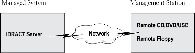
13
Managing Virtual Media
Virtual media allows the managed server to access media devices on the management station or ISO CD/DVD images on
a network share as if they were devices on the managed server.
Using the Virtual Media feature, you can:
• Remotely access media connected to a remote system over the network
• Install applications
• Update drivers
• Install an operating system on the managed system
This is a licensed feature for rack and tower servers. It is available by default for blade servers.
The key features are:
• Virtual Media supports virtual optical drives (CD/DVD), floppy drives (including USB-based drives), and USB flash
drives.
• You can attach only one floppy, USB flash drive, image, or key and one optical drive on the management station to a
managed system. Supported floppy drives include a floppy image or one available floppy drive. Supported optical
drives include a maximum of one available optical drive or one ISO image file.
The following figure shows a typical Virtual Media setup.
• Virtual floppy media of iDRAC7 is not accessible from virtual machines.
• Any connected Virtual Media emulates a physical device on the managed system.
• On Windows-based managed systems, the Virtual Media drives are auto-mounted if they are attached and
configured with a drive letter.
• On Linux-based managed systems with some configurations, the Virtual Media drives are not auto-mounted. To
manually mount the drives, use the mount command.
• All the virtual drive access requests from the managed system are directed to the management station across the
network.
• Virtual devices appear as two drives on the managed system without the media being installed in the drives.
• You can share the management station CD/DVD drive (read only), but not a USB media, between two managed
systems.
• Virtual media requires a minimum available network bandwidth of 128 Kbps.
• If LOM or NIC failover occurs, then the Virtual Media session may be disconnected.
Figure 4. Virtual Media Setup
191

Supported Drives and Devices
The following table lists the drives supported through virtual media.
Table 25. Supported Drives and Devices
Drive Supported Storage Media
Virtual Optical Drives • Legacy 1.44 floppy drive with a 1.44 floppy diskette
• CD-ROM
• DVD
• CD-RW
• Combination drive with CD-ROM media
Virtual floppy drives • CD-ROM/DVD image file in the ISO9660 format
• Floppy image file in the ISO9660 format
USB flash drives • USB CD-ROM drive with CD-ROM media
• USB Key image in the ISO9660 format
Configuring Virtual Media
Before you configure the Virtual Media settings, make sure that you have configured your Web browser to use Java or
ActiveX plug-in.
Related Links
Configuring Web Browsers to Use Virtual Console
Configuring Virtual Media Using iDRAC7 Web Interface
To configure virtual media settings:
CAUTION: Do not reset iDRAC7 when running a Virtual Media session. Otherwise, undesirable results may occur,
including data loss.
1. In the iDRAC7 Web interface, go to Overview → Server → Attached Media.
2. Specify the required settings. For more information, see the
iDRAC7 Online Help
.
3. Click Apply to save the settings.
Configuring Virtual Media Using RACADM
To configure the virtual media,
• Use the objects in the iDRAC.VirtualMedia group with the set command.
• Use the objects in the cfgRacVirtual group with the config command.
For more information, see the
RACADM Command Line Reference Guide for iDRAC7 and CMC
available at dell.com/
support/manuals.
192

Configuring Virtual Media Using iDRAC Settings Utility
You can attach, detach, or auto-attach virtual media using the iDRAC Settings utility. To do this:
1. In the iDRAC Settings utility, go to Virtual Media.
The iDRAC Settings Virtual Media page is displayed.
2. Select Detach, Attach, or Auto attach based on the requirement. For more information about the options, see
iDRAC
Settings Utility Online Help
.
3. Click Back, click Finish, and then click Yes.
The Virtual Media settings are configured.
Attached Media State and System Response
The following table describes the system response based on the Attached Media setting.
Table 26. Attached Media State and System Response
Attached Media State System Response
Detach Cannot map an image to the system.
Attach Media is mapped even when Client View is closed.
Auto-attach Media is mapped when Client View is opened and unmapped when Client View is closed.
Accessing Virtual Media
You can access Virtual Media with or without using the Virtual Console. Before you access Virtual Media, make sure to
configure your Web browser(s).
Virtual Media and RFS are mutually exclusive. If the RFS connection is active and you attempt to launch the Virtual
Media client, the following error message is displayed:
Virtual Media is currently unavailable. A Virtual Media or Remote
File Share session is in use.
If the RFS connection is not active and you attempt to launch the Virtual Media client, the client launches successfully.
You can then use the Virtual Media client to map devices and files to the Virtual Media virtual drives.
Related Links
Configuring Web Browsers to Use Virtual Console
Configuring Virtual Media
Launching Virtual Media Using Virtual Console
Before you launch Virtual Media through the Virtual Console, make sure that:
• Virtual Console is enabled.
• System is configured to not hide empty drives — In Windows Explorer, navigate to Folder Options, clear the Hide
empty drives in the Computer folder option, and click OK.
193

To access Virtual Media using Virtual Console:
1. In the iDRAC7 Web interface, go to Overview → Server → Virtual Console.
The Virtual Console page is displayed.
2. Click Launch Virtual Console.
The Virtual Console Viewer is launched.
NOTE: On Linux, Java is the default plug-in type for accessing the Virtual Console. On Windows, open the.jnlp
file to launch the Virtual Console using Java.
3. Click Virtual Media → Connect Virtual Media.
The Virtual Media session is established and the Virtual Media menu displays the list of devices available for
mapping.
NOTE: The Virtual Console Viewer window must remain active while you access the Virtual Media.
.
Related Links
Configuring Web Browsers to Use Virtual Console
Configuring Virtual Media
Disabling Warning Messages While Launching Virtual Console Or Virtual Media Using Java or ActiveX Plug-in
Launching Virtual Media Without Using Virtual Console
Before you launch Virtual Media when the Virtual Console is disabled, make sure that
• Virtual Media is in
Attach
state.
• System is configured to unhide empty drives. To do this, in Windows Explorer, navigate to Folder Options, clear the
Hide empty drives in the Computer folder option, and click OK.
To launch Virtual Media when Virtual Console is disabled:
1. In the iDRAC7 Web Interface, go to Overview → Server → Virtual Console.
The Virtual Console page is displayed.
2. Click Launch Virtual Console.
The following message is displayed:
Virtual Console has been disabled. Do you want to continue using Virtual
Media redirection?
3. Click OK .
The Virtual Media window is displayed.
4. From the Virtual Media menu, click Map CD/DVD or Map Removable Disk.
For more information, see Mapping Virtual Drive.
NOTE: The virtual device drive letters on the managed system do not coincide with the physical drive letters
on the management station.
NOTE: The Virtual Media may not function correctly on Windows operating system clients that are configured
with Internet Explorer Enhanced Security. To resolve this issue, see the Microsoft operating system
documentation or contact the system administrator.
Related Links
Configuring Virtual Media
194

Disabling Warning Messages While Launching Virtual Console Or Virtual Media Using Java or ActiveX Plug-in
Adding Virtual Media Images
You can create a media image of the remote folder and mount it as a USB attached device to the server’s operating
system. To add Virtual Media images:
1. Click Virtual Media → Create Image....
2. In the Source Folder field, click Browse and browse to the folder or directory to be used as the source for the
image file. The image file is on the management station or the C: drive of the managed system.
3. In the Image File Name field, the default path to store the created image files (typically the desktop directory)
appears. To change this location, click Browse and navigate to a location.
4. Click Create Image.
The image creation process starts. If the image file location is within the source folder, a warning message is
displayed indicating that the image creation cannot proceed as the image file location within the source folder
causes an infinite loop. If the image file location is not within the source folder, then the image creation proceeds.
After the image is created, a success message is displayed.
5. Click Finish.
The image is created.
When a folder is added as an image, a .img file is created on the Desktop of the management station from which
this feature is used. If this .img file is moved or deleted, then the corresponding entry for this folder in the Virtual
Media menu does not work. Therefore, it is recommended not to move or delete the .img file while the
image
is
being used. However, the .img file can be removed after the relevant entry is first deselected and then removed
using Remove Image to remove the entry.
Viewing Virtual Device Details
To view the virtual device details, in the Virtual Console Viewer, click Tools → Stats. In the Stats window, the Virtual
Media section displays the mapped virtual devices and the read/write activity for each device. If Virtual Media is
connected, this information is displayed. If Virtual Media is not connected, the “Virtual Media is not connected”
message is displayed.
If the Virtual Media is launched without using the Virtual Console, then the Virtual Media section is displayed as a dialog
box. It provides information about the mapped devices.
Resetting USB
To reset the USB device:
1. In the Virtual Console viewer, click Tools → Stats.
The Stats window is displayed.
2. Under Virtual Media, click USB Reset.
A message is displayed warning the user that resetting the USB connection can affect all the input to the target
device including Virtual Media, keyboard, and mouse.
3. Click Yes.
The USB is reset.
NOTE: iDRAC7 Virtual Media does not terminate even after you log out of iDRAC7 Web interface session.
195

Mapping Virtual Drive
To map the virtual drive:
NOTE: While using ActiveX-based Virtual Media, you must have administrative privileges to map an operating
system DVD or a USB flash drive (that is connected to the management station.) To map the drives, launch IE as
an administrator or add the iDRAC7 IP address to the list of trusted sites.
1. To establish a Virtual Media session, from the Virtual Media menu, click Connect Virtual Media.
For each device available for mapping from the host server, a menu item appears under the Virtual Media menu.
The menu item is named according to the device type such as:
– Map CD/DVD
– Map Removable Disk
– Map Floppy Disk
NOTE: The Map Floppy Disk menu item appears on the list if the Floppy Emulation option is enabled on the
Attached Media page. When Floppy Emulation is enabled, Map Removable Disk is replaced with Map Floppy
Disk.
2. Click the device type that you want to map.
NOTE: The active session displays if a Virtual Media session is currently active from the current Web
interface session, from another Web interface session, or from VMCLI.
3. In the Drive/Image File field, select the device from the drop-down list.
The list contains all the available (unmapped) devices that you can map (CD/DVD, Removable Disk, Floppy Drive)
and image file types that you can map (ISO or IMG). The image files are located in the default image file directory
(typically the user’s desktop). If the device is not available in the drop-down list, click Browse to specify the device.
The correct file type for CD/DVD is ISO and for removable disk and floppy disk it is IMG.
If the image is created in the default path (Desktop), when you select Map Removable Disk, the created image is
available for selection in the drop-down menu.
If image is created in a different location, when you select Map Removable Disk, the created image is not available
for selection in the drop-down menu. Click Browse to specify the image.
4. Select Read-only to map writable devices as read-only.
For CD/DVD devices, this option is enabled by default and you cannot disable it.
5. Click Map Device to map the device to the host server.
After the device/file is mapped, the name of its Virtual Media menu item changes to indicate the device name. For
example, if the CD/DVD device is mapped to an image file named foo.iso, then the CD/DVD menu item on the Virtual
Media menu is named foo.iso mapped to CD/DVD. A check mark for that menu item indicates that it is mapped.
Related Links
Displaying Correct Virtual Drives For Mapping
Adding Virtual Media Images
196

Displaying Correct Virtual Drives For Mapping
On a Linux-based management station, the Virtual Media Client window may display removable disks and floppy disks
that are not part of the management station. To make sure that the correct virtual drives are available to map, you must
enable the port setting for the connected SATA hard drive. To do this:
1. Reboot the operating system on the management station. During POST, press <F2> or <F12> to enter System Setup.
2. Go to SATA settings. The port details are displayed.
3. Enable the ports that are actually present and connected to the hard drive.
4. Access the Virtual Media Client window. It displays the correct drives that can be mapped.
Related Links
Mapping Virtual Drive
Unmapping Virtual Drive
To ummap the virtual drive:
1. From the Virtual Media menu, do any of the following:
– Click the device that you want to unmap.
– Click Disconnect Virtual Media.
A message appears asking for confirmation.
2. Click Yes.
The check mark for that menu item does not appear indicating that it is not mapped to the host server.
Setting Boot Order Through BIOS
Using the System BIOS Settings utility, you can set the managed system to boot from virtual optical drives or virtual
floppy drives.
NOTE: Changing Virtual Media while connected may stop the system boot sequence.
To enable the managed system to boot:
1. Boot the managed system.
2. Press <F2> to enter the System Setup page.
3. Go to System BIOS Settings → Boot Settings → BIOS Boot Settings → Boot Sequence.
In the pop-up window, the virtual optical drives and virtual floppy drives are listed with the standard boot devices.
4. Make sure that the virtual drive is enabled and listed as the first device with bootable media. If required, follow the
on-screen instructions to modify the boot order.
5. Click OK, navigate back to System BIOS Settings page, and click Finish.
6. Click Yes to save the changes and exit.
The managed system reboots.
The managed system attempts to boot from a bootable device based on the boot order. If the virtual device is
connected and a bootable media is present, the system boots to the virtual device. Otherwise, the system overlooks
the device—similar to a physical device without bootable media.
197

Enabling Boot Once for Virtual Media
You can change the boot order only once when you boot after attaching remote Virtual Media device.
Before you enable the boot once option, make sure that:
• You have
Configure User
privilege.
• Map the local or virtual drives (CD/DVD, Floppy, or USB flash device) with the bootable media or image using the
Virtual Media options
• Virtual Media is in
Attached
state for the virtual drives to appear in the boot sequence.
To enable the boot once option and boot the managed system from the Virtual Media:
1. In the iDRAC7 Web interface, go to Overview → Server → Attached Media.
2. Under Virtual Media, select the Enable Boot Once and click Apply.
3. Turn on the managed system and press <F2> during boot.
4. Change the boot sequence to boot from the remote Virtual Media device.
5. Reboot the server.
The managed system boots once from the Virtual Media.
Related Links
Mapping Virtual Drive
Configuring Virtual Media
198

14
Installing and Using VMCLI Utility
The Virtual Media Command Line Interface (VMCLI) utility is an interface that provides virtual media features from the
management station to iDRAC7 on the managed system. Using this utility you can access virtual media features,
including image files and physical drives, to deploy an operating system on multiple remote systems in a network.
NOTE: You can run the VMCLI utility only on the management station that is installed with 32–bit operating system.
The VMCLI utility supports the following features:
• Manage removable devices or images that are accessible through virtual media.
• Automatically terminate the session when the iDRAC7 firmware Boot Once option is enabled.
• Secure communications to iDRAC7 using Secure Sockets Layer (SSL).
• Execute VMCLI commands until:
– The connections automatically terminate.
– An operating system terminates the process.
NOTE: To terminate the process in Windows, use the Task Manager.
Installing VMCLI
The VMCLI utility is included in the
Dell Systems Management Tools and Documentation
DVD.
To install the VMCLI utility:
1. Insert the
Dell Systems Management Tools and Documentation
DVD into the management station’s DVD drive.
2. Follow the on-screen instructions to install DRAC tools.
3. After successful install, check install\Dell\SysMgt\rac5 folder to make sure vmcli.exe exists. Similarly, check the
respective path for UNIX.
The VMCLI utility is installed on the system.
Running VMCLI Utility
• If the operating system requires specific privileges or group membership, you require similar privileges to run the
VMCLI commands.
• On Windows systems, non-administrators must have Power User privileges to run the VMCLI utility.
• On Linux systems, to access iDRAC7, run VMCLI utility, and log user commands, non-administrators must prefix
sudo to the VMCLI commands. However, to add or edit users in the VMCLI administrators group, use the visudo
command.
VMCLI Syntax
The VMCLI interface is identical on both Windows and Linux systems. The VMCLI syntax is:
VMCLI [parameter] [operating_system_shell_options]
For example, vmcli -r iDRAC7-IP-address:iDRAC7-SSL-port
199

The
parameter
enables VMCLI to connect to the specified server, access iDRAC7, and map to the specified virtual
media.
NOTE: VMCLI syntax is case-sensitive.
To ensure security, it is recommended to use the following VMCLI parameters:
•vmcli -i — Enables an interactive method of starting VMCLI. It ensures that the user name and password are
not visible when processes are examined by other users.
• vmcli -r <iDRAC7-IP-address[:iDRAC7-SSL-port]> -S -u <iDRAC7-user-name> -p
<iDRAC7-user-password> -c {< device-name > | < image-file >} — Indicates whether the
iDRAC7 CA certificate is valid. If the certificate is not valid, a warning message is displayed when you run this
command. However, the command is executed successfully and a VMCLI session is established. For more
information on VMCLI parameters, see the
VMCLI Help
or the
VMCLI Man pages
.
Related Links
VMCLI Commands to Access Virtual Media
VMCLI Operating System Shell Options
VMCLI Commands to Access Virtual Media
The following table provides the VMCLI commands required for accessing different virtual media.
Table 27. VMCLI Commands
Virtual Media Command
Floppy drive vmcli -r [RAC IP or hostname] -u
[iDRAC7 user
name] -p [iDRAC7 user password] -f
[device name]
Bootable floppy or USB key image vmcli -r [iDRAC7 IP address] [iDRAC7
user name]
-p [iDRAC7 password] -f [floppy.img]
CD drive using -f option vmcli -r [iDRAC7 IP address] -u
[iDRAC7 user name]
-p [iDRAC7 password] -f [device name]|
[image file]-f [cdrom - dev
]
Bootable CD/DVD image vmcli -r [iDRAC7 IP address] -u
[iDRAC7 user name]
-p [iDRAC7 password] -c [DVD.img]
If the file is not write-protected, Virtual Media may write to the image file. To make sure that Virtual Media does not
write to the media:
• Configure the operating system to write-protect a floppy image file that must not be overwritten.
• Use the write-protection feature of the device.
When virtualizing read-only image files, multiple sessions can use the same image media simultaneously.
When virtualizing physical drives, only one session can access a given physical drive at a time.
VMCLI Operating System Shell Options
VMCLI uses shell options to enable the following operating system features:
200

• stderr/stdout redirection — Redirects any printed utility output to a file.
For example, using the greater-than character (>) followed by a filename overwrites the specified file with the
printed output of the VMCLI utility.
NOTE: The VMCLI utility does not read from standard input (stdin). Hence, stdin redirection is not required.
• Background execution — By default, the VMCLI utility runs in the foreground. Use the operating system's command
shell features for the utility to run in the background.
For example, under a Linux operating system, the ampersand character (&) following the command causes the
program to be spawned as a new background process. This technique is useful in script programs, as it allows the
script to proceed after a new process is started for the VMCLI command (otherwise, the script blocks until the
VMCLI program is terminated).
When multiple VMCLI sessions are started, use the operating system-specific facilities for listing and terminating
processes.
201
202

15
Managing vFlash SD Card
The vFlash SD card is a Secure Digital (SD) card that plugs into the vFlash SD card slot in the system. You can use a card
with a maximum of 16 GB capacity. After you insert the card, you must enable vFlash functionality to create and manage
partitions. vFlash is a licensed feature.
If the card is not available in the system's vFlash SD card slot, the following error message is displayed in the iDRAC7
Web interface at Overview → Server → vFlash:
SD card not detected. Please insert an SD card of size 256MB or greater.
NOTE: Make sure that you only insert a vFlash compatible SD card in the iDRAC7 vFlash card slot. If you insert a
non-compatible SD card, the following error message is displayed when you initialize the card:
An error has
occurred while initializing SD card.
The key features are:
• Provides storage space and emulates USB device (s).
• Create up to 16 partitions. These partitions, when attached, are exposed to the system as a Floppy drive, Hard Disk
drive, or a CD/DVD drive depending on the selected emulation mode.
• Create partitions from supported file system types. Supports .img format for floppy, .iso format for CD/DVD, and
both .iso and .img formats for Hard Disk emulation types.
• Create bootable USB device(s).
• Boot once to an emulated USB device.
NOTE: It is possible that a vFlash license may expire during a vFlash operation. If it happens, the on-going
vFlash operations complete normally.
Configuring vFlash SD Card
Before configuring vFlash, make sure that the vFlash SD card is installed on the system. For information on how to install
and remove the card from your system, see the system's
Hardware Owner’s Manual
at dell.com/support/manuals.
NOTE: You must have Configure iDRAC7 permission to enable or disable vFlash functionality, and initialize the
card.
Related Links
Viewing vFlash SD Card Properties
Enabling or Disabling vFlash Functionality
Initializing vFlash SD Card
Viewing vFlash SD Card Properties
After vFlash functionality is enabled, you can view the SD card properties using iDRAC7 Web interface or RACADM.
Viewing vFlash SD Card Properties Using Web Interface
To view the vFlash SD card properties, in the iDRAC7 Web interface, go to Overview → Server → vFlash. The SD Card
Properties page is displayed. For information about the displayed properties, see the
iDRAC7 Online Help
.
203

Viewing vFlash SD Card Properties Using RACADM
To view the vFlash SD card properties using RACADM, use one of the following:
• Use the cfgvFlashSD object with the getconfig command. The following read-only properties are displayed:
– cfgVFlashSDSize
– cfgVFlashSDLicensed
– cfgVFlashSDAvailableSize
– cfgVFlashSDHealth
– cfgVFlashSDEnable
– cfgVFlashSDWriteProtect
– cfgVFlashSDInitialized
• Use the following objects with the get command:
– iDRAC.vflashsd.AvailableSize
– iDRAC.vflashsd.Health
– iDRAC.vflashsd.Licensed
– iDRAC.vflashsd.Size
– iDRAC.vflashsd.WriteProtect
For more information about these objects, see the
RACADM Command Line Reference Guide for iDRAC7 and CMC
available at dell.com/support/manuals or dell.com/esmamanuals.
Viewing vFlash SD Card Properties Using iDRAC Settings Utility
To view the vFlash SD card properties, in the iDRAC Settings Utility, go to vFlash Media. The iDRAC Settings vFlash
Media page displays the properties. For information about the displayed properties, see the
iDRAC Settings Utility Online
Help
.
Enabling or Disabling vFlash Functionality
You must enable the vFlash functionality to perform partition management.
Enabling or Disbaling vFlash Functionality Using Web Interface
To enable or disable the vFlash functionality:
1. In the iDRAC7 Web interface, go to Overview → Server → vFlash .
The SD Card Properties page is displayed.
2. Select or clear the vFLASH Enabled option to enable or disable the vFlash functionality. If any vFlash partition is
attached, you cannot disable vFlash and an error message is displayed.
NOTE: If vFlash functionality is disabled, SD card properties are not displayed.
3. Click Apply. The vFlash functionality is enabled or disabled based on the selection.
Enabling or Disabling vFlash Functionality Using RACADM
To enable or disable the vFlash functionality using RACADM, use one of the following:
• Using config command:
– To enable vFlash:
racadm config -g cfgvFlashsd -o cfgvflashSDEnable 1
204

– To disable vFlash:
racadm config -g cfgvFlashsd -o cfgvflashSDEnable 0
• Using set command:
– To enable vFlash:
racadm set iDRAC.vflashsd.Enable 1
– To disable vFlash:
racadm set iDRAC.vflashsd.Enable 0
NOTE: The RACADM command functions only if a vFlash SD card is present. If a card is not present, the following
message is displayed:
ERROR: SD Card not present
.
Enabling or Disabling vFlash Functionality Using iDRAC Settings Utility
To enable or disable the vFlash functionality:
1. In the iDRAC Settings utility, go to vFlash Media.
The iDRAC Settings vFlash Media page is displayed.
2. Select Enabled to enable vFlash functionality or select Disabled to disable the vFlash functionality.
3. Click Back, click Finish, and then click Yes.
The vFlash functionality is enabled or disabled based on the selection.
Initializing vFlash SD Card
The initialize operation reformats the SD card and configures the initial vFlash system information on the card.
Initializing vFlash SD Card Using Web Interface
To initialize the vFlash SD card:
1. In the iDRAC7 Web interface, go to Overview → Server → vFlash .
The SD Card Properties page is displayed.
2. Enable vFLASH and click Initialize.
All existing contents are removed and the card is reformatted with the new vFlash system information.
If any vFlash partition is attached, the initialize operation fails and an error message is displayed.
Initializing vFlash SD Card Using RACADM
To initialize the vFlash SD card using RACADM, use one of the following:
• Using vFlashSD command:
racadm vflashsd initialize
• Using set command:
racadm set iDRAC.vflashsd.Initialized 1
All existing partitions are deleted and the card is reformatted.
For more information about these commands, see the
RACADM Command Line Reference Guide for iDRAC7 and CMC
available at dell.com/support/manuals and dell.com/esmmanuals.
205

Initializing vFlash SD Card Using iDRAC Settings Utility
To initialize the vFlash SD card using iDRAC Settings utility:
1. In the iDRAC Settings utility, go to vFlash Media.
The iDRAC Settings vFlash Media page is displayed.
2. Click Initialize vFlash.
3. Click Yes. The initialization operation starts.
4. Click Back and navigate to the same iDRAC Settings vFlash Media page to view the successful message.
All existing contents are removed and the card is reformatted with the new vFlash system information.
Getting the Last Status Using RACADM
To get the status of the last initialize command sent to the vFlash SD card:
1. Open a telnet, SSH, or Serial console to the system and log in.
2. Enter the command: racadm vFlashsd status
The status of commands sent to the SD card is displayed.
3. To get the last status of all the vflash partitions, use the command:racadm vflashpartition status -a
4. To get the last status of a particular partition, use command:racadm vflashpartition status -i
(index)
NOTE: If iDRAC7 is reset, the status of the last partition operation is lost.
Managing vFlash Partitions
You can perform the following using the iDRAC7 Web interface or RACADM:
NOTE: An administrator can perform all operations on the vFlash partitions. Else, you must have Access Virtual
Media privilege to create, delete, format, attach, detach, or copy the contents for the partition.
•Creating an Empty Partition
•Creating a Partition Using an Image File
•Formatting a Partition
•Viewing Available Partitions
•Modifying a Partition
•Attaching or Detaching Partitions
•Deleting Existing Partitions
•Downloading Partition Contents
•Booting to a Partition
NOTE: If you click any option on the vFlash pages when an application such as WS-MAN, iDRAC Settings utility, or
RACADM is using vFlash, or if you navigate to some other page in the GUI, iDRAC7 may display the message:
vFlash is currently in use by another process. Try again after some time.
vFlash is capable of performing fast partition creation when there is no other on-going vFlash operation such as
formatting, attaching partitions, and so on. Therefore, it is recommended to first create all partitions before performing
other individual partition operations.
206
Creating an Empty Partition
An empty partition, when attached to the system, is similar to an empty USB flash drive. You can create empty partitions
on a vFlash SD card. You can create partitions of type
Floppy
or
Hard Disk
. The partition type CD is supported only while
creating partitions using images.
Before creating an empty partition, make sure that:
• You have Access Virtual Media privilege.
• The card is initialized.
• The card is not write-protected.
• An initialize operation is not being performed on the card.
Creating an Empty Partition Using the Web Interface
To create an empty vFlash partition:
1. In iDRAC7 Web interface, go to Overview → Server → vFlash → Create Empty Partition.
The Create Empty Partition page is displayed.
2. Specify the required information and click Apply. For information about the options, see the
iDRAC7 Online Help
.
A new unformatted empty partition is created that is read-only by default. A page indicating the progress
percentage is displayed. An error message is displayed if:
– The card is write-protected.
– The label name matches the label of an existing partition.
– A non-integer value is entered for the partition size, the value exceeds the available space on the card, or the
partition size is greater than 4 GB.
– An initialize operation is being performed on the card.
Creating an Empty Partition Using RACADM
To create a 20 MB empty partition:
1. Open a telnet, SSH, or Serial console to the system and log in.
2. Enter the command: racadm vflashpartition create -i 1 -o drive1 -t empty -e HDD -f
fat16 -s 20
A 20 MB empty partition in FAT16 format is created. By default, an empty partition is created as read-write.
Creating a Partition Using an Image File
You can create a new partition on the vFlash SD card using an image file (available in the .img or .iso format.) The
partitions are of emulation types: Floppy (.img), Hard Disk (.img or .iso), or CD (.iso). The created partition size is equal to
the image file size.
Before creating a partition from an image file, make sure that:
• You have Access Virtual Media privilege.
• The card is initialized.
• The card is not write-protected.
• An initialize operation is not being performed on the card.
• The image type and the emulation type match.
207

NOTE: The uploaded image and the emulation type must match. There are issues when iDRAC7 emulates a
device with incorrect image type. For example, if the partition is created using an ISO image and the emulation
type is specified as Hard Disk, then the BIOS cannot boot from this image.
• Image file size is less than or equal to the available space on the card.
• Image file size is less than or equal to 4 GB as the maximum partition size supported is 4 GB. However, while
creating a partition using a Web browser, the image file size must be less than 2 GB.
Creating a Partition Using an Image File Using Web Interface
To create a vFlash partition from an image file:
1. In iDRAC7 Web interface, go to Overview → Server → vFlash → Create From Image.
The Create Partition from Image File page is displayed.
2. Enter the required information and click Apply. For information about the options, see the
iDRAC7 Online Help
.
A new partition is created. For CD emulation type, a read-only partition is created. For Floppy or Hard Disk
emulation type, a read-write partition is created. An error message is displayed if:
– The card is write-protected
– The label name matches the label of an existing partition.
– The size of the image file is greater than 4GB or exceeds the available space on the card.
– The image file does not exist or the image file extension is neither .img nor .iso.
– An initialize operation is already being performed on the card.
Creating a Partition From an Image File Using RACADM
To create a partition from an image file using RACADM:
1. Open a telnet, SSH, or Serial console to the system and log in.
2. Enter the command: racadm vflashpartition create –i 1 –o drive1 –e HDD –t image –
l //myserver/sharedfolder/foo.iso –u root –p mypassword
A new partition is created. By default, the created partition is read-only. This command is case sensitive for the
image file name extension. If the file name extension is in upper case, for example FOO.ISO instead of FOO.iso, then
the command returns a syntax error.
NOTE: This feature is not supported in local RACADM.
NOTE: Creating vFlash partition from an image file located on the CFS or NFS IPv6 enabled network share is
not supported.
Formatting a Partition
You can format an existing partition on the vFlash SD card based on the type of file system. The supported file system
types are EXT2, EXT3, FAT16, and FAT32. You can only format partitions of type Hard Disk or Floppy, and not CD. You
cannot format read-only partitions.
Before creating an partition from an image file, make sure that:
• You have Access Virtual Media privilege.
• The card is initialized.
• The card is not write-protected.
• An initialize operation is not being performed on the card.
208

To format vFlash partition:
1. In iDRAC7 Web interface, go to Overview → Server → vFlash → Format.
The Format Partition page is displayed.
2. Enter the required information and click Apply.
For information about the options, see the
iDRAC7 Online Help
.
A warning message indicating that all the data on the partition will be erased is displayed.
3. Click OK.
The selected partition is formatted to the specified file system type. An error message is displayed if:
– The card is write-protected.
– An initialize operation is already being performed on the card.
Viewing Available Partitions
Make sure that the vFlash functionality is enabled to view the list of available partitions.
Viewing Available Partitions Using Web Interface
To view the available vFlash partitions, in the iDRAC7 Web interface, go to Overview → Server → vFlash → Manage.
The Manage Partitions page is displayed listing the available partitions and related information for each partition. For
information on the partitions, see the
iDRAC7 Online Help
.
Viewing Available Partitions Using RACADM
To view the available partitions and their properties using RACADM:
1. Open a Telnet, SSH, or Serial console to the system and log in.
2. Enter the following commands:
– To list all existing partitions and its properties:
racadm vflashpartition list
– To get the status of operation on partition 1:
racadm vflashpartition status -i 1
– To get the status of all existing partitions:
racadm vflashpartition status -a
NOTE: The -a option is valid only with the status action.
Modifying a Partition
You can change a read-only partition to read-write or vice-versa. Before modifying the partition, make sure that:
• The vFlash functionality is enabled.
• You have Access Virtual Media privileges.
NOTE: By default, a read-only partition is created.
209

Modifying a Partition Using Web Interface
To modify a partition:
1. In the iDRAC7 Web interface, go to Overview → Server → vFlash → Manage.
The Manage Partitions page is displayed.
2. In the Read-Only column:
– Select the checkbox for the partition(s) and click Apply to change to read-only.
– Clear the checkbox for the partition(s) and click Apply to change to read-write.
The partitions are changed to read-only or read-write, based on the selections.
NOTE: If the partition is of type CD, the state is read-only. You cannot change the state to read-write. If the
partition is attached, the check box is grayed-out.
Modifying a Partition Using RACADM
To view the available partitions and their properties on the card:
1. Open a telnet, SSH, or Serial console to the system and log in.
2. Use any one of the following:
– Using config command to change the read-write state of the partition:
* To change a read-only partition to read-write:
racadm config –g cfgvflashpartition –i 1 –o
cfgvflashPartitionAccessType 1
* To change a read-write partition to read-only:
racadm config –g cfgvflashpartition –i 1 –o
cfgvflashPartitionAccessType 0
– Using set command to change the read-write state of the partition:
* To change a read-only partition to read-write:
racadm set iDRAC.vflashpartition.<index>.AccessType 1
* To change a read-write partition to read-only:
racadm set iDRAC.vflashpartition.<index>.AccessType 0
– Using set command to specify the Emulation type:
racadm set iDRAC.vflashpartition.<index>.EmulationType <HDD, Floppy, or
CD-DVD>
Attaching or Detaching Partitions
When you attach one or more partitions, they are visible to the operating system and BIOS as USB mass storage
devices. When you attach multiple partitions, based on the assigned index, they are listed in an ascending order in the
operating system and the BIOS boot order menu.
If you detach a partition, it is not visible in the operating system and the BIOS boot order menu.
When you attach or detach a partition, the USB bus in the managed system is reset. This affects applications that are
using vFlash and disconnects the iDRAC7 Virtual Media sessions.
Before attaching or detaching a partition, make sure that:
• The vFlash functionality is enabled.
210
• An initialize operation is not already being performed on the card.
• You have Access Virtual Media privileges.
Attaching or Detaching Partitions Using Web Interface
To attach or detach partitions:
1. In the iDRAC7 Web interface, go to Overview → Server → vFlash → Manage.
The Manage Partitions page is displayed.
2. In the Attached column:
– Select the checkbox for the partition(s) and click Apply to attach the partition(s).
– Clear the checkbox for the partition(s) and click Apply to detach the partition(s).
The partitions are attached or detached, based on the selections.
Attaching or Detaching Partitions Using RACADM
To attach or detach partitions:
1. Open a telnet, SSH, or Serial console to the system and log in.
2. Use any one of the following:
– Using config command:
* To attach a partition:
racadm config –g cfgvflashpartition –i 1 –o
cfgvflashPartitionAttachState 1
* To detach a partition:
racadm config –g cfgvflashpartition –i 1 –o
cfgvflashPartitionAttachState 0
– Using set command:
* To attach a partition:
racadm set iDRAC.vflashpartition.<index>.AttachState 1
* To detach a partition:
racadm set iDRAC.vflashpartition.<index>.AttachState 0
Operating System Behavior for Attached Partitions
For Windows and Linux operating systems:
• The operating system controls and assigns the drive letters to the attached partitions.
• Read-only partitions are read-only drives in the operating system.
• The operating system must support the file system of an attached partition. Else, you cannot read or modify the
contents of the partition from the operating system. For example, in a Windows environment the operating system
cannot read the partition type EXT2 which is native to Linux. Also, in a Linux environment the operating system
cannot read the partition type NTFS which is native to Windows.
• The vFlash partition label is different from the volume name of the file system on the emulated USB device. You can
change the volume name of the emulated USB device from the operating system. However, it does not change the
partition label name stored in iDRAC7.
Deleting Existing Partitions
Before deleting existing partition(s), make sure that:
211

• The vFlash functionality is enabled.
• The card is not write-protected.
• The partition is not attached.
• An initialize operation is not being performed on the card.
Deleting Existing Partitions Using Web Interface
To delete an existing partition:
1. In the iDRAC7 Web interface, go to Overview → Server → vFlash → Manage.
The Manage Partitions page is displayed.
2. In the Delete column, click the delete icon for the partition that you want to delete.
A message is displayed indicating that this action permanently deletes the partition.
3. Click OK.
The partition is deleted.
Deleting Existing Partitions Using RACADM
To delete partitions:
1. Open a telnet, SSH, or Serial console to the system and log in.
2. Enter the following commands:
– To delete a partition:
racadm vflashpartition delete -i 1
– To delete all partitions, re-initialize the vFlash SD card.
Downloading Partition Contents
You can download the contents of a vFlash partition in the .img or .iso format to the:
• Managed system (where iDRAC7 is operated from)
• Network location mapped to a management station.
Before downloading the partition contents, make sure that:
• You have Access Virtual Media privileges.
• The vFlash functionality is enabled.
• An initialize operation is not being performed on the card.
• For a read-write partition, it must not be attached.
To download the contents of the vFlash partition:
1. In the iDRAC7 Web interface, go to Overview → Server → vFlash → Download.
The Download Partition page is displayed.
2. From the Label drop-down menu, select a partition that you want to download and click Download.
NOTE: All existing partitions (except attached partitions) are displayed in the list. The first partition is selected
by default.
212

3. Specify the location to save the file.
The contents of the selected partition are downloaded to the specified location.
NOTE: If only the folder location is specified, then the partition label is used as the file name, along with the
extension .iso for CD and Hard Disk type partitions, and .img for Floppy and Hard Disk type partitions.
Booting to a Partition
You can set an attached vFlash partition as the boot device for the next boot operation.
Before booting a partition, make sure that:
• The vFlash partition contains a bootable image (in the .img or .iso format) to boot from the device.
• The vFlash functionality is enabled.
• You have Access Virtual Media privileges.
Booting to a Partition Using Web Interface
To set the vFlash partition as a first boot device, see Setting First Boot Device.
NOTE: If the attached vFlash partition(s) are not listed in the First Boot Device drop-down menu, make sure that
the BIOS is updated to the latest version.
Booting to a Partition Using RACADM
To set a vFlash partition as the first boot device, use cfgServerInfo. For more information, see the
RACADM
Command Line Reference Guide for iDRAC7 and CMC
available at dell.com/support/manuals.
NOTE: When you run this command, the vFlash partition label is automatically set to boot once—
cfgserverBootOnce is set to 1. Boot once boots the device to the partition only once and does not keep it
persistently first in the boot order.
213
214

16
Using SMCLP
The Server Management Command Line Protocol (SMCLP) specification enables CLI-based systems management. It
defines a protocol for management commands transmitted over standard character oriented streams. This protocol
accesses a Common Information Model Object Manager (CIMOM) using a human-oriented command set. The SMCLP is
a sub-component of the Distributed Management Task Force (DMTF) SMASH initiative to streamline systems
management across multiple platforms. The SMCLP specification, along with the Managed Element Addressing
Specification and numerous profiles to SMCLP mapping specifications, describes the standard verbs and targets for
various management task executions.
NOTE: It is assumed that you are familiar with the Systems Management Architecture for Server Hardware
(SMASH) Initiative and the SMWG SMCLP specifications.
The SM-CLP is a subcomponent of the Distributed Management Task Force (DMTF) SMASH initiative to streamline
server management across multiple platforms. The SM-CLP specification, along with the Managed Element Addressing
Specification and numerous profiles to SM-CLP mapping specifications, describes the standard verbs and targets for
various management task executions.
The SMCLP is hosted from the iDRAC7 controller firmware and supports Telnet, SSH, and serial-based interfaces. The
iDRAC7 SMCLP interface is based on the SMCLP Specification Version 1.0 provided by the DMTF organization.
NOTE: Information about the profiles, extensions, and MOFs are available at delltechcenter.com and all DMTF
information is available at dmtf.org/standards/profiles/.
SM-CLP commands implement a subset of the local RACADM commands. The commands are useful for scripting since
you can execute these commands from a management station command line. You can retrieve the output of commands
in well-defined formats, including XML, facilitating scripting and integration with existing reporting and management
tools.
System Management Capabilities Using SMCLP
iDRAC7 SMCLP enables you to:
• Manage Server Power — Turn on, shut down, or reboot the system
• Manage System Event Log (SEL) — Display or clear the SEL records
• Manage iDRAC7 user account
• View system properties
Running SMCLP Commands
You can run the SMCLP commands using SSH or Telnet interface. Open a SSH or Telnet interface and log in to iDRAC7
as an administrator. The SMCLP prompt (admin ->)is displayed.
SMCLP prompts:
• yx1x blade servers use -$.
• yx1x rack and tower servers use admin->.
215

• yx2x blade, rack, and tower servers use admin->.
where, y is a alpha-numeric character such as M (for blade servers), R (for rack servers), and T (for tower servers) and x
is a number. This indicates the generation of Dell PowerEdge servers.
NOTE: Scripts using -$ can use these for yx1x systems, but starting with yx2x systems one script with admin->
can be used for blade, rack, and tower servers.
iDRAC7 SMCLP Syntax
The iDRAC7 SMCLP uses the concept of verbs and targets to provide systems management capabilities through the CLI.
The verb indicates the operation to perform, and the target determines the entity (or object) that runs the operation.
The SMCLP command line syntax:
<verb> [<options>] [<target>] [<properties>]
The following table provides the verbs and its definitions.
Table 28. SMCLP Verbs
Verb Definition
cd Navigates through the MAP using the shell
set Sets a property to a specific value
help Displays help for a specific target
reset Resets the target
show Displays the target properties, verbs, and subtargets
start Turns on a target
stop Shuts down a target
exit Exits from the SMCLP shell session
version Displays the version attributes of a target
load Moves a binary image to a specified target address from a
URL
The following table provides a list of targets.
Table 29. SMCLP Targets
Target Definitions
admin1 admin domain
admin1/profiles1 Registered profiles in iDRAC7
admin1/hdwr1 Hardware
admin1/system1 Managed system target
admin1/system1/capabilities1 Managed system SMASH collection capabilities
admin1/system1/capabilities1/pwrcap1 Managed system power utilization capabilities
admin1/system1/capabilities1/elecap1 Managed system target capabilities
admin1/system1/logs1 Record Log collections target
216

Target Definitions
admin1/system1/logs1/log1 System Event Log (SEL) record entry
admin1/system1/logs1/log1/record* An individual SEL record instance on the managed system
admin1/system1/settings1 Managed system SMASH collection settings
admin1/system1/capacities1 Managed system capacities SMASH collection
admin1/system1/consoles1 Managed system consoles SMASH collection
admin1/system1/sp1 Service Processor
admin1/system1/sp1/timesvc1 Service Processor time service
admin1/system1/sp1/capabilities1 Service processor capabilities SMASH collection
admin1/system1/sp1/capabilities1/
clpcap1
CLP service capabilities
admin1/system1/sp1/capabilities1/
pwrmgtcap1
Power state management service capabilities on the
system
admin1/system1/sp1/capabilities1/
acctmgtcap*
Account management service capabilities
admin1/system1/sp1/capabilities1/
rolemgtcap*
Local Role Based Management capabilities
admin1/system1/sp1/capabilities/
PwrutilmgtCap1
Power utilization management capabilities
admin1/system1/sp1/capabilities1/
elecap1
Authentication capabilities
admin1/system1/sp1/settings1 Service Processor settings collection
admin1/system1/sp1/settings1/
clpsetting1
CLP service settings data
admin1/system1/sp1/clpsvc1 CLP service protocol service
admin1/system1/sp1/clpsvc1/clpendpt* CLP service protocol endpoint
admin1/system1/sp1/clpsvc1/tcpendpt* CLP service protocol TCP endpoint
admin1/system1/sp1/jobq1 CLP service protocol job queue
admin1/system1/sp1/jobq1/job* CLP service protocol job
admin1/system1/sp1/pwrmgtsvc1 Power state management service
admin1/system1/sp1/account1-16 Local user account
admin1/sysetm1/sp1/account1-16/
identity1
Local user identity account
217

Target Definitions
admin1/sysetm1/sp1/account1-16/
identity2
IPMI identity (LAN) account
admin1/sysetm1/sp1/account1-16/
identity3
IPMI identity (Serial) account
admin1/sysetm1/sp1/account1-16/
identity4
CLP identity account
admin1/system1/sp1/acctsvc1 Local user account management service
admin1/system1/sp1/acctsvc2 IPMI account management service
admin1/system1/sp1/acctsvc3 CLP account management service
admin1/system1/sp1/rolesvc1 Local Role Base Authorization (RBA) service
admin1/system1/sp1/rolesvc1/Role1-16 Local role
admin1/system1/sp1/rolesvc1/Role1-16/
privilege1
Local role privilege
admin1/system1/sp1/rolesvc2 IPMI RBA service
admin1/system1/sp1/rolesvc2/Role1-3 IPMI role
admin1/system1/sp1/rolesvc2/Role4 IPMI Serial Over LAN (SOL) role
admin1/system1/sp1/rolesvc3 CLP RBA Service
admin1/system1/sp1/rolesvc3/Role1-3 CLP role
admin1/system1/sp1/rolesvc3/Role1-3/
privilege1
CLP role privilege
Related Links
Running SMCLP Commands
Usage Examples
Navigating the MAP Address Space
Objects that can be managed with SM-CLP are represented by targets arranged in a hierarchical space called the
Manageability Access Point (MAP) address space. An address path specifies the path from the root of the address
space to an object in the address space.
The root target is represented by a slash (/) or a backslash (\). It is the default starting point when you log in to iDRAC7.
Navigate down from the root using the cd verb.
NOTE: The slash (/) and backslash (\) are interchangeable in SM-CLP address paths. However, a backslash at the
end of a command line continues the command on the next line and is ignored when the command is parsed.
For example to navigate to the third record in the System Event Log (SEL), enter the following command:
->cd /admin1/system1/logs1/log1/record3
Enter the cd verb with no target to find your current location in the address space. The .. and . abbreviations work as
they do in Windows and Linux: .. refers to the parent level and . refers to the current level.
218

Using Show Verb
To learn more about a target use the show verb. This verb displays the target’s properties, sub-targets, associations,
and a list of the SM-CLP verbs that are allowed at that location.
Using the -display Option
The show –display option allows you to limit the output of the command to one or more of properties, targets,
associations, and verbs. For example, to display just the properties and targets at the current location, use the following
command:
show -display properties,targets
To list only certain properties, qualify them, as in the following command:
show –d properties=(userid,name) /admin1/system1/sp1/account1
If you only want to show one property, you can omit the parentheses.
Using the -level Option
The show -level option executes show over additional levels beneath the specified target. To see all targets and
properties in the address space, use the -l all option.
Using the -output Option
The -output option specifies one of four formats for the output of SM-CLP verbs: text, clpcsv, keyword, and clpxml.
The default format is text, and is the most readable output. The clpcsv format is a comma-separated values format
suitable for loading into a spreadsheet program. The keyword format outputs information as a list of keyword=value
pairs one per line. The clpxml format is an XML document containing a response XML element. The DMTF has specified
the clpcsv and clpxml formats and their specifications can be found on the DMTF website at dmtf.org.
The following example shows how to output the contents of the SEL in XML:
show -l all -output format=clpxml /admin1/system1/logs1/log1
Usage Examples
This section provides use case scenarios for SMCLP:
•Server Power Management
•SEL Management
•MAP Target Navigation
Server Power Management
The following examples show how to use SMCLP to perform power management operations on a managed system.
Type the following commands at the SMCLP command prompt:
• To switch off the server:
stop /system1
The following message is displayed:
system1 has been stopped successfully
219
• To switch on the server:
start /system1
The following message is displayed:
system1 has been started successfully
• To reboot the server:
reset /system1
The following message is displayed:
system1 has been reset successfully
SEL Management
The following examples show how to use the SMCLP to perform SEL-related operations on the managed system. Type
the following commands at the SMCLP command prompt:
• To view the SEL:
show/system1/logs1/log1
The following output is displayed:
/system1/logs1/log1
Targets:
Record1
Record2
Record3
Record4
Record5
Properties:
InstanceID = IPMI:BMC1 SEL Log
MaxNumberOfRecords = 512
CurrentNumberOfRecords = 5
Name = IPMI SEL
EnabledState = 2
OperationalState = 2
HealthState = 2
Caption = IPMI SEL
Description = IPMI SEL
ElementName = IPMI SEL
Commands:
cd
show
help
exit
version
• To view the SEL record:
show/system1/logs1/log1
The following output is displayed:
/system1/logs1/log1/record4
220
Properties:
LogCreationClassName= CIM_RecordLog
CreationClassName= CIM_LogRecord
LogName= IPMI SEL
RecordID= 1
MessageTimeStamp= 20050620100512.000000-000
Description= FAN 7 RPM: fan sensor, detected a failure
ElementName= IPMI SEL Record
Commands:
cd
show
help
exit
version
• To clear the SEL:
delete /system1/logs1/log1/record*
The following output is displayed:
All records deleted successfully
MAP Target Navigation
The following examples show how to use the cd verb to navigate the MAP. In all examples, the initial default target is
assumed to be /.
Type the following commands at the SMCLP command prompt:
• To navigate to the system target and reboot:
cd system1 reset The current default target is /.
• To navigate to the SEL target and display the log records:
cd system1
cd logs1/log1
show
• To display current target:
type cd .
• To move up one level:
type cd ..
• To exit:
exit
221
222

17
Using iDRAC Service Module
iDRAC monitoring currently depends on OpenManage Server Administrator to provide information about the host, such
as the operating system and host name. The iDRAC Service Module is a software application that is recommended to be
installed on the server (it is not installed by default). It complements iDRAC with monitoring information from the
operating system. It does not have an interface but, complements iDRAC by providing additional data to work with iDRAC
interfaces such as the Web interface, RACADM, and WSMAN. You can configure the features monitored by the iDRAC
Service Module to control the CPU and memory consumed on the server’s operating system.
NOTE: You can use the iDRAC Service Module only if you have installed iDRAC Express or iDRAC Enterprise
license.
Before using iDRAC Service Module, make sure that:
• You have Login, Configure, and Server Control privileges in iDRAC to enable or disable the iDRAC Service Module
features.
• OS to iDRAC pass-through feature is enabled through the internal USB bus in iDRAC7.
NOTE:
– When iDRAC Service Module runs for the first time, by default it enables the OS to iDRAC pass-through
channel in iDRAC. If you disable this feature after installing the iDRAC Service Module, then you must
enable it manually in iDRAC.
– If the OS to iDRAC pass-through channel is enabled through LOM in iDRAC7, then you cannot use the
iDRAC Service Module.
Installing iDRAC Service Module
You can download and install the iDRAC Service Module from dell.com/support. You must have administrator privilege
on the sever’s operating system to install the iDRAC Service Module. For information on installation, see the
iDRAC
Service Module Installation Guide
available at dell.com/support/manuals.
iDRAC Service Module Monitoring Features
The iDRAC Service Module provides the following monitoring features:
• Operating System (OS) information
• Replicate Lifecycle Controller logs to operating system logs
• Automatic system recovery options
Operating System Information
OpenManage Server Administrator currently shares operating system information and host name with iDRAC. The
iDRAC Service Module provides similar information such as OS name, OS version, and Fully Qualified Domain Name
(FQDN) with iDRAC. By default, this monitoring feature is enabled. It is not disabled if OpenManage Server Administrator
is installed on the host OS.
223
Replicate Lifecycle Logs to OS Log
You can replicate the Lifecycle Controller Logs to the OS logs from the time when the feature is enabled in iDRAC. This is
similar to the System Event Log (SEL) replication performed by OpenManage Server Administrator. All events that have
the OS Log option selected as the target (in the Alerts page, or in the equivalent RACADM or WSMAN interfaces) are
replicated in the OS log using the iDRAC Service Module. The default set of logs to be included in the OS logs is the
same as configured for SNMP alerts or traps.
iDRAC Service Module also logs the events that have occurred when the operating system is not functioning. The OS
logging performed by iDRAC Service Module follows the IETF syslog standards for Linux based operating systems.
If OpenManage Server Administrator is installed, this monitoring feature is disabled to avoid duplicate SEL entries in the
OS log.
Automatic System Recovery Options
You can perform automatic system recovery operations such as reboot, power cycle, or power off the server after a
specified time interval. This feature is enabled only if the operating system watchdog timer is disabled. If OpenManage
Server Administrator is installed, this monitoring feature is disabled to avoid duplicate watchdog timers.
Co-existence of OpenManage Server Administrator and iDRAC Service Module
In a system, both OpenManage Server Administrator and the iDRAC Service Module can co-exist and continue to
function correctly and independently.
If you have enabled the monitoring features during the iDRAC Service Module installation, then after the installation is
complete if the iDRAC Service Module detects the presence of OpenManage Server Administrator, it disables the set of
monitoring features that overlap. If OpenManage Server Administrator is running, the iDRAC Service Module disables
the overlapping monitoring features after logging to the OS and iDRAC.
When you re-enable these monitoring features through the iDRAC interfaces at a later time, the same checks are
performed and the features are enabled depending on whether OpenManage Server Administrator is running or not.
Using iDRAC Service Module From iDRAC Web Interface
To use the iDRAC Service Module from the iDRAC Web interface:
1. Go to Overview → Server → Service Module.
The iDRAC Service Module Setup page is displayed.
2. You can view the following:
– Installed iDRAC Service Module version on the host operating system
– Connection status of the iDRAC Service Module with iDRAC.
224
3. To perform out-of-band monitoring functions, select one or more of the following options:
–OS Information — View the operating system information.
–Replicate Lifecycle Log in OS Log — Include Lifecycle Controller logs to operating system logs. This option is
disabled if OpenManage Server Administrator is installed on the system.
–Auto System Recovery Action — Perform auto recovery operations on the system after a specified time (in
seconds):
*Reboot
*Power Off System
*Power Cycle System
This option is disabled if OpenManage Server Administrator is installed on the system.
Using iDRAC Service Module From RACADM
To use the iDRAC Service Module from RACADM, use the objects in the ServiceModule group. For more information, see
the
RACADM Command Line Reference Guide for iDRAC7 and CMC
available at dell.com/support/manuals.
225
226

18
Deploying Operating Systems
You can use any of the following utilities to deploy operating systems to managed systems:
• Virtual Media Command Line Interface (CLI)
• Virtual Media Console
• Remote File Share
Related Links
Deploying Operating System Using VMCLI
Deploying Operating System Using Remote File Share
Deploying Operating System Using Virtual Media
Deploying Operating System Using VMCLI
Before you deploy the operating system using the vmdeploy script, make sure that:
• VMCLI utility is installed on the management station.
•Configure User and Access Virtual Media privileges for iDRAC7 are enabled for the user.
• IPMItool is installed on the management station.
NOTE: IPMItool does not work if IPv6 is configured either on the managed system or the management station.
• iDRAC7 is configured on the target remote systems.
• System is able to boot from the image file.
• IPMI Over LAN is enabled in iDRAC7.
• Network share contains drivers and operating system bootable image file, in an industry standard format such
as .img or .iso.
NOTE: While creating the image file, follow standard network-based installation procedures, and mark the
deployment image as read-only to make sure that each target system boots and executes the same
deployment procedure.
• Virtual Media status is in attach state.
•vmdeploy script is installed on the management station. Review this sample vmdeploy script included with VMCLI.
The script describes how to deploy the operating system to remote systems in the network. It internally uses VMCLI
and IPMItool.
NOTE: The vmdeploy script is dependent on some support files in the directory during installation. To use the
script from another directory, copy all the files with it. If the IPMItool utility is not installed, copy the utility
along with the other files.
To deploy the operating system on target remote systems:
1. List the iDRAC7 IPv4 addresses of the target remote systems, in the ip.txt text file. List one IPv4 address per line.
2. Insert a bootable operating system, CD or DVD, into the management station drive.
227

3. Open a command prompt with administrator privileges and run the vmdeploy script:
vmdeploy.bat -r <iDRAC7-IPAddress or file> -u <iDRAC7-user> -p <iDRAC7-user-
passwd> [ -f {<floppy-image> | < device-name>} | -c { <device-name>|<image-
file>} ] [-i <DeviceID>]
NOTE: vmdeploy does not support IPv6, since IPv6 does not support the IPMI tool.
NOTE: The vmdeploy script processes the -r option slightly differently than the vmcli -r option. If the
argument to the -r option is the name of an existing file, the script reads iDRAC7 IPv4 or IPv6 addresses from
the specified file and runs the utility once for each line. If the argument to the -r option is not a filename,
then it should a single iDRAC7 address. In this case, the -r works as described for the VMCLI utility.
The following table describes the vmdeploy command parameters.
Table 30. vmdeploy Command Parameters
Parameter Description
<iDRAC7-user> iDRAC7 user name. It must have the following
attributes:
– Valid user name
– iDRAC7 Virtual Media User permission
If iDRAC7 authentication fails, an error message is
displayed and the command is terminated.
<iDRAC7-ip | file> iDRAC7 IP address or the file containing the iDRAC7 IP
address.
<iDRAC7-user-password> or <iDRAC7-
passwd>
Password for the iDRAC7 user.
If iDRAC7 authentication fails, an error message is
displayed and the command is terminated.
-c {<device-name> | <image-file>} Path to an ISO9660 image of the operating system
installation CD or DVD.
<floppy-device> Path to the device containing the operating system
installation CD, DVD, or Floppy.
<floppy-image> Path to a valid floppy image.
<Device ID> ID of the device to boot once.
Related Links
Configuring Virtual Media
Configuring iDRAC7
Deploying Operating System Using Remote File Share
Before you deploy the operating system using Remote File Share (RFS), make sure that:
•Configure User and Access Virtual Media privileges for iDRAC7 are enabled for the user.
• Network share contains drivers and operating system bootable image file, in an industry standard format such
as .img or .iso.
NOTE: While creating the image file, follow standard network-based installation procedures, and mark the
deployment image as read-only to make sure that each target system boots and executes the same
deployment procedure.
228

To deploy an operating system using RFS:
1. Using Remote File Share (RFS), mount the ISO or IMG image file to the managed system through NFS or CIFS.
2. Go to Overview → Setup → First Boot Device .
3. Set the boot order in the First Boot Device drop-down list to Remote File Share.
4. Select the Boot Once option to enable the managed system to reboot using the image file for the next instance only.
5. Click Apply.
6. Reboot the managed system and follow the on-screen instructions to complete the deployment.
Related Links
Managing Remote File Share
Setting First Boot Device
Managing Remote File Share
Using Remote File Share (RFS) feature, you can set an ISO or IMG image file on a network share and make it available to
the managed server’s operating system as a virtual drive by mounting it as a CD or DVD using NFS or CIFS. RFS is a
licensed feature.
NOTE: IPv4 address is supported for both CIFS and NFS. IPv6 address is supported only for CIFS.
Remote file share supports only .img and .iso image file formats. A .img file is redirected as a virtual floppy and a .iso file
is redirected as a virtual CDROM.
You must have Virtual Media privileges to perform an RFS mounting.
NOTE: If ESXi is running on the managed system and if you mount a floppy image (.img) using RFS, the connected
floppy image is not available to the ESXi operating system.
RFS and Virtual Media features are mutually exclusive.
• If the Virtual Media client is not active, and you attempt to establish an RFS connection, the connection is
established and the remote image is available to the host operating system.
• If the Virtual Media client is active, and you attempt to establish an RFS connection, the following error message is
displayed:
Virtual Media is detached or redirected for the selected virtual drive.
The connection status for RFS is available in iDRAC7 log. Once connected, an RFS-mounted virtual drive does not
disconnect even if you log out from iDRAC7. The RFS connection is closed if iDRAC7 is reset or the network connection
is dropped. The Web interface and command-line options are also available in CMC and iDRAC7 to close the RFS
connection. The RFS connection from CMC always overrides an existing RFS mount in iDRAC7.
NOTE: iDRAC7 vFlash feature and RFS are not related.
If you update the iDRAC firmware from version 1.30.30 to 1.50.50 firmware while there is an active RFS connection and
the Virtual Media Attach Mode is set to Attach or Auto Attach, the iDRAC attempts to re-establish the RFS connection
after the firmware upgrade is completed and the iDRAC reboots.
If you update the iDRAC firmware from version 1.30.30 to 1.50.50 firmware while there is an active RFS connection and
the Virtual Media Attach Mode is set to Detach, the iDRAC does not attempt to re-establish the RFS connection after the
firmware upgrade is completed and the iDRAC reboots.
229

Configuring Remote File Share Using Web Interface
To enable remote file sharing:
1. In iDRAC7 Web interface, go to Overview → Server → Attached Media.
The Attached Media page is displayed.
2. Under Attached Media, select Attach or Auto Attach.
3. Under Remote File Share, specify the image file path, domain name, user name, and password. For information
about the fields, see the
iDRAC7 Online Help
.
Example for image file path:
– CIFS — //<IP to connect for CIFS file system>/<file path>/<image name>
– NFS —< IP to connect for NFS file system>/<file path>/<image name>
NOTE: Both '/' or '\' characters can be used for the file path.
CIFS supports both IPv4 and IPv6 addresses but NFS supports only IPv4 address.
If you are using NFS share, make sure that you provide the exact <file path> and <image name> as it is case-
sensitive.
4. Click Apply and then click Connect.
After the connection is established, the Connection Status displays Connected.
NOTE: Even if you have configured remote file sharing, the Web interface does not display user credential
information due to security reasons.
For Linux distributions, this feature may require a manual mount command when operating at runlevel init 3. The
syntax for the command is:
mount /dev/OS_specific_device / user_defined_mount_point
where, user_defined_mount_point is any directory you choose to use for the mount similar to any mount
command.
For RHEL, the CD device (.iso virtual device) is /dev/scd0 and floppy device (.img virtual device) is /dev/sdc.
For SLES, the CD device is /dev/sr0 and the floppy device is /dev/sdc. To make sure that the correct device is
used (for either SLES or RHEL), when you connect the virtual device, on the Linux OS you must immediately run the
command:
tail /var/log/messages | grep SCSI
This displays the text that identifies the device (example, SCSI device sdc). This procedure also applies to Virtual
Media when you are using Linux distributions in runlevel init 3. By default, the virtual media is not auto-mounted in
init 3.
Configuring Remote File Share Using RACADM
To configure remote file share using RACADM, use:
racadm remoteimage
racadm remoteimage <options>
Options are:
–c : connect image
–d : disconnect image
–u <username>: username to access the network share
230

–p <password>: password to access the network share
–l <image_location>: image location on the network share; use double quotes around the location. See examples for
image file path in Configuring Remote File Share Using Web Interface section
–s : display current status
NOTE: All characters including alphanumeric and special characters are allowed as part of user name, password,
and image_location except the following characters: ’ (single quote), “(double quote), ,(comma), < (less than), and
> (greater than).
Deploying Operating System Using Virtual Media
Before you deploy the operating system using Virtual Media, make sure that:
• Virtual Media is in
Attached
state for the virtual drives to appear in the boot sequence.
• If Virtual Media is in
Auto Attached
mode, the Virtual Media application must be launched before booting the
system.
• Network share contains drivers and operating system bootable image file, in an industry standard format such
as .img or .iso.
To deploy an operating system using Virtual Media:
1. Do one of the following:
– Insert the operating system installation CD or DVD into the management station CD or DVD drive.
– Attach the operating system image.
2. Select the drive on the management station with the required image to map it.
3. Use one of the following methods to boot to the required device:
– Set the boot order to boot once from Virtual Floppy or Virtual CD/DVD/ISO using the iDRAC7 Web interface.
– Set the boot order through System Setup → System BIOS Settings by pressing <F2> during boot.
4. Reboot the managed system and follow the on-screen instructions to complete the deployment.
Related Links
Configuring Virtual Media
Setting First Boot Device
Configuring iDRAC7
Installing Operating System From Multiple Disks
1. Unmap the existing CD/DVD.
2. Insert the next CD/DVD into the remote optical drive.
3. Remap the CD/DVD drive.
Deploying Embedded Operating System On SD Card
To install an embedded hypervisor on an SD card:
1. Insert the two SD cards in the Internal Dual SD Module (IDSDM) slots on the system.
2. Enable SD module and redundancy (if required) in BIOS.
3. Verify if the SD card is available on one of the drives when you <F11> during boot.
231

4. Deploy the embedded operating system and follow the operating system installation instructions.
Related Links
About IDSDM
Enabling SD Module and Redundancy in BIOS
Enabling SD Module and Redundancy in BIOS
To enable SD module and redundancy in BIOS:
1. Press <F2> during boot.
2. Go to System Setup → System BIOS Settings → Integrated Devices.
3. Set the Internal USB Port to On. If it is set to Off, the IDSDM is not available as a boot device.
4. If redundancy is not required (single SD card), set Internal SD Card Port to On and Internal SD Card Redundancy to
Disabled.
5. If redundancy is required (two SD cards), set Internal SD Card Port to On and Internal SD Card Redundancy to
Mirror.
6. Click Back and click Finish.
7. Click Yes to save the settings and press <Esc> to exit System Setup.
About IDSDM
Internal Dual SD Module (IDSDM) is available only on applicable platforms. IDSDM provides redundancy on the
hypervisor SD card by using another SD card that mirrors the first SD card’s content.
Either of the two SD cards can be the master. For example, if two new SD cards are installed in the IDSDM, SD1 is active
(master) card and SD2 is the standby card. The data is written on both the cards, but the data is read from SD1. At any
time if SD1 fails or is removed, SD2 automatically become the active (master) card.
You can view the status, health, and the availability of IDSDM using iDRAC7 Web Interface or RACADM. The SD card
redundancy status and failure events are logged to SEL, displayed on the front panel, and PET alerts are generated if
alerts are enabled.
Related Links
Viewing Sensor Information
232

19
Troubleshooting Managed System Using iDRAC7
You can diagnose and troubleshoot a remote managed system using:
• Diagnostic console
• Post code
• Boot and crash capture videos
• Last system crash screen
• System event logs
• Lifecycle logs
• Front panel status
• Trouble indicators
• System health
Related Links
Using Diagnostic Console
Scheduling Remote Automated Diagnostics
Viewing Post Codes
Viewing Boot and Crash Capture Videos
Viewing Logs
Viewing Last System Crash Screen
Viewing Front Panel Status
Hardware Trouble Indicators
Viewing System Health
Generating Tech Support Report
Using Diagnostic Console
iDRAC7 provides a standard set of network diagnostic tools that are similar to the tools included with Microsoft
Windows or Linux-based systems. Using iDRAC7 Web interface, you can access the network debugging tools.
To access Diagnostics Console:
1. In the iDRAC7 Web interface, go to Overview → Server → Troubleshooting → Diagnostics.
2. In the Command text box, enter a command and click Submit. For information about the commands, see the
iDRAC7
Online Help
.
The results are displayed on the same page.
Scheduling Remote Automated Diagnostics
You can remotely invoke automated offline diagnostics on a server as a one-time event and return the results. If the
diagnostics require a reboot, you can reboot immediately or stage it for a subsequent reboot or maintenance cycle
(similar to updates). When diagnostics are run, the results are collected and stored in the internal iDRAC storage. You
can then export the results to an NFS or CIFS network share using the diagnostics export racadm command.
233

You can also run diagnostics using the appropriate WSMAN command(s). For more information, see the WSMAN
documentation.
You must have iDRAC7 Express license to use remote automated diagnostics.
You can perform the diagnostics immediately or schedule it on a particular day and time, specify the type of diagnostics,
and the type of reboot.
For the schedule, you can specify the following:
• Start time – Run the diagnostic at a future day and time. If you specify TIME NOW, the diagnostic is run on the next
reboot.
• End time - Run the diagnostic until a date and time after the Start time. If it is not started by End time, it is marked as
failed with End time expired. If you specify TIME NA, then the wait time is not applicable.
The types of diagnostic tests are:
• Express test
• Extended test
• Both in a sequence
The types of reboot are:
• Power cycle system
• Graceful shutdown (waits for operating system to turn off or for system restart)
• Forced Graceful shutdown (signals operating system to turn off and waits for 10 minutes. If the operating system
does not turn off, the iDRAC power cycles the system)
Only one diagnostic job can be scheduled or run at one time. A diagnostic job can complete successfully, complete with
error, or is unsuccessful. The diagnostic events including the results are recorded in Lifecycle Controller log. You can
retrieve the results of the last diagnostic execution using remote RACADM or WSMAN.
You can export the diagnostic results of the last completed diagnostics that were scheduled remotely to a network
share such as CIFS or NFS. The maximum file size is 5 MB.
You can cancel a diagnostic job when the status of the job is Unscheduled or Scheduled. If the diagnostic is running,
then restart the system to cancel the job.
Before you run the remote diagnostics, make sure that:
• Lifecycle Controller is enabled.
• You have Login and Server Control privileges.
Scheduling Remote Automated Diagnostics Using RACADM
To run the remote diagnostics and save the results on the local system, use the following command:
racadm diagnostics run -m <Mode> -r <reboot type> -s <Start Time> -e
<Expiration Time>
To export the last run remote diagnostics results, use the following command:
racadm diagnostics export -f <file name> -l <NFS / CIFS share> -u <username> -p
<password>
For more information about the options, see the
RACADM Command Line Reference Guide for iDRAC7 and CMC
available at dell.com/support/manuals.
234

Viewing Post Codes
Post codes are progress indicators from the system BIOS, indicating various stages of the boot sequence from power-
on-reset, and allows you to diagnose any faults related to system boot-up. The Post Codes page displays the last system
post code prior to booting the operating system.
To view the Post Codes, go to Overview → Server → Troubleshooting → Post Code.
The Post Code page displays the system health indicator, a hexadecimal code, and a description of the code.
Viewing Boot and Crash Capture Videos
You can view the video recordings of:
• Last three boot cycles — A boot cycle video logs the sequence of events for a boot cycle. The boot cycle videos are
arranged in the order of latest to oldest.
• Last crash video — A crash video logs the sequence of events leading to the failure.
This is a licensed feature.
iDRAC7 records fifty frames during boot time. Playback of the boot screens occur at a rate of 1 frame per second. If
iDRAC7 is reset, the boot capture video is not available as it is stored in RAM and is deleted.
NOTE: You must have Access Virtual Console or administrator privileges to playback the Boot Capture and Crash
Capture videos.
To view the Boot Capture screen, click Overview → Server → Troubleshooting → Video Capture.
The Video Capture screen displays the video recordings. For more information, see the
iDRAC7 Online Help
.
Viewing Logs
You can view System Event Logs (SELs) and Lifecycle logs. For more information, see Viewing System Event Log and
Viewing Lifecycle Log .
Viewing Last System Crash Screen
The last crash screen feature captures a screenshot of the most recent system crash, saves, and displays it in iDRAC7.
This is a licensed feature.
To view the last crash screen:
1. Make sure that the last system crash screen feature is enabled.
2. In iDRAC7 Web interface, go to Overview → Server → Troubleshooting → Last Crash Screen.
The Last Crash Screen page displays the last saved crash screen from the managed system.
Click Clear to delete the last crash screen.
Related Links
Enabling Last Crash Screen
Viewing Front Panel Status
The Front Panel on the managed system summarizes the status of the following components in the system:
235

• Batteries
• Fans
• Intrusion
• Power Supplies
• Removable Flash Media
• Temperatures
• Voltages
You can view the status of the front panel of the managed system:
• For rack and tower servers: LCD front panel and system ID LED status or LED front panel and system ID LED status.
• For blade servers: Only system ID LEDs.
Viewing System Front Panel LCD Status
To view the LCD front panel status for applicable rack and tower servers, in iDRAC7 Web interface, go to Overview →
Hardware → Front Panel . The Front Panel page displays.
The Live Front Panel Feed section displays the live feed of the messages currently being displayed on the LCD front
panel. When the system is operating normally (indicated by Solid Blue color in the LCD front panel), then both Hide Error
and UnHide Error is grayed-out. You can hide or unhide the errors only for rack and tower servers.
To view LCD front panel status using RACADM, use the objects in the System.LCD group. For more information, see
the
RACADM Command Line Reference Guide for iDRAC7 and CMC
available at dell.com/support/manuals.
Related Links
Configuring LCD Setting
Viewing System Front Panel LED Status
To view the current system ID LED status, in iDRAC7 Web interface, go to Overview → Hardware → Front Panel. The
Live Front Panel Feed section displays the current front panel status:
• Solid blue — No errors present on the managed system.
• Blinking blue — Identify mode is enabled (regardless of managed system error presence).
• Solid amber — Managed system is in failsafe mode.
• Blinking amber — Errors present on managed system.
When the system is operating normally (indicated by blue Health icon on the LED front panel), then both Hide Error and
UnHide Error is grayed-out. You can hide or unhide the errors only for rack and tower servers.
To view system ID LED status using RACADM, use the getled command. For more information, see the
RACADM
Command Line Reference Guide for iDRAC7 and CMC
available at dell.com/support/manuals.
Related Links
Configuring System ID LED Setting
Hardware Trouble Indicators
The hardware related problems are:
• Failure to power up
• Noisy fans
• Loss of network connectivity
236

• Hard drive failure
• USB media failure
• Physical damage
Based on the problem, use the following methods to correct the problem:
• Reseat the module or component and restart the system
• In case of a blade server, insert the module into a different bay in the chassis
• Replace hard drives or USB flash drives
• Reconnect or replace the power and network cables
If problem persists, see the
Hardware Owner’s Manual
for specific troubleshooting information about the hardware
device.
CAUTION: You should only perform troubleshooting and simple repairs as authorized in your product
documentation, or as directed by online or telephone service and support team. Damage due to servicing that is
not authorized by Dell is not covered by your warranty. Read and follow the safety instructions that came with the
product.
Viewing System Health
iDRAC7 and CMC (for blade servers) Web interfaces display the status for the following:
• Batteries
• Fans
• Intrusion
• Power Supplies
• Removable Flash Media
• Temperatures
• Voltages
• CPU
In iDRAC7 Web interface, go to Overview → Server → System Summary → Server Health section.
To view CPU health, go to Overview → Hardware → CPU.
The system health indicators are:
• — Indicates a normal status.
• — Indicates a warning status.
• — Indicates a failure status.
• — Indicates an unknown status.
Click any component name in the Server Health section to view details about the component.
Generating Tech Support Report
If you have to work with Tech Support on an issue with a server but the security policies restrict direct internet
connection, then you can provide Tech Support with necessary data to facilitate troubleshooting of the problem without
having to install software or download tools from Dell and without having access to the Internet from the server
237
operating system or iDRAC. You can send the report from an alternate system and be certain that the data collected
from your server is not viewable by non-authorized individuals during the transmission to Tech Support.
You can generate a health report of the server and then export the report to a location on the management station (local)
or to a shared network location such as Common Internet File System (CIFS) or Network File Share (NFS). You can then
share this report directly with the Tech Support. To export to a network share such as CIFS or NFS, direct network
connectivity to the iDRAC shared or dedicated network port is required.
The report is generated in the standard ZIP format. The report contains information that is similar to the information
available in the DSET report, but only hardware information and most recent Lifecycle Controller log entries (archived
entries are not included).
After the report is generated, you can delete information that you do not want to share with the tech support.
Each time the the data collection is performed, an event is recorded in the Lifecycle Controller log. The event includes
information such as the interface used, the date and time of export, and iDRAC user name.
Generating Tech Support Report Using Web Interface
Before generating the report, make sure that:
• Lifecycle Controller and Collect System Inventory On Reboot (CSIOR) are enabled.
• You have Login and Server Control privileges.
To generate the Tech Support Report:
1. In the iDRAC Web interface, go to Overview → Server → Troubleshooting → Tech Support Report.
The Tech Support Report page is displayed.
2. Select one of the following:
–Local to export the report to a location on the local system
–Network to export the report to a network share and specify the network settings.
For information about the fields, see the
iDRAC7 Online Help
.
3. Click Export.
The information is collected and exported to the specified location in .zip format.
If you export the report without Login and Server Control privileges, an error message is displayed.
If Lifecycle Controller is disabled or in recovery state, a warning message and the steps to enable Lifecycle
Controller is displayed.
If CSIOR is disabled, a message is displayed indicating that the data being exported may not be the latest data.
Checking Server Status Screen for Error Messages
When a flashing amber LED is blinking, and a particular server has an error, the main Server Status Screen on the LCD
highlights the affected server in orange. Use the LCD navigation buttons to highlight the affected server, then click the
center button. Error and warning messages will be displayed on the second line. For the list of error messages displayed
on the LCD panel, see the server’s Owner’s Manual.
Restarting iDRAC7
You can perform a hard or soft iDRAC7 restart without turning off the server:
• Hard restart — On the server, press and hold the LED button for 15 seconds.
238
• Soft restart — Using iDRAC7 Web interface or RACADM.
Resetting iDRAC7 Using iDRAC7 Web Interface
To restart iDRAC7, do one of the following in the iDRAC7 Web interface:
• Go to Overview → Server → Summary. Under Quick Launch Tasks, click Reset iDRAC.
• Go to Overview → Server → Troubleshooting → Diagnostics. Click Reset iDRAC.
Resetting iDRAC7 Using RACADM
To restart iDRAC7, use the racreset command. For more information, see the
RACADM Reference Guide for iDRAC7 and
CMC
available at dell.com/support/manuals.
Resetting iDRAC7 to Factory Default Settings
You can reset iDRAC7 to the factory default settings using the iDRAC Settings utility or the iDRAC7 Web interface.
Resetting iDRAC7 to Factory Default Settings Using iDRAC7 Web Interface
To reset iDRAC7 to factory default settings using the iDRAC7 Web interface:
1. Go to Overview → Server → Troubleshooting → Diagnostics.
The Diagnostics Console page is displayed.
2. Click Reset iDRAC to Default Settings.
The completion status is displayed in percentage. iDRAC7 reboots and is restored to factory defaults. The iDRAC7
IP is reset and is not accessible. You can configure the IP using the front panel or BIOS.
Resetting iDRAC7 to Factory Default Settings Using iDRAC Settings Utility
To reset iDRAC7 to factory default values using the iDRAC Settings utility:
1. Go to Reset iDRAC configurations to defaults.
The iDRAC Settings Reset iDRAC configurations to defaults page is displayed.
2. Click Yes.
iDRAC reset starts.
3. Click Back and navigate to the same Reset iDRAC configurations to defaults page to view the success message.
239
240

20
Frequently Asked Questions
This section lists the frequently asked questions for the following:
•System Event Log
•Network Security
•Active Directory
•Single Sign On
•Smart Card Login
•Virtual Console
•Virtual Media
•vFlash SD Card
•SNMP Authentication
•Storage Devices
•RACADM
•Miscellaneous
System Event Log
While using iDRAC7 Web interface through Internet Explorer, why does SEL not save using the Save As option?
This is due to a browser setting. To resolve this:
1. In Internet Explorer, go to Tools → Internet Options → Security and select the zone you are attempting to
download in.
For example, if the iDRAC7 device is on the local intranet, select Local Intranet and clickCustom level... .
2. In the Security Settingswindow, under Downloadsmake sure that the following options are enabled:
– Automatic prompting for file downloads (if this option is available)
– File download
CAUTION: To make sure that the computer used to access iDRAC7 is safe, underMiscellaneous , do not
enable theLaunching applications and unsafe files option.
Network Security
While accessing the iDRAC7 Web interface, a security warning appears stating that the SSL certificate issued by the
Certificate Authority (CA) is not trusted.
iDRAC7 includes a default iDRAC7 server certificate to ensure network security while accessing through the Web-based
interface and remote RACADM. This certificate is not issued by a trusted CA. To resolve this, upload a iDRAC7 server
certificate issued by a trusted CA (for example, Microsoft Certificate Authority, Thawte or Verisign).
Why the DNS server not registering iDRAC7?
Some DNS servers register iDRAC7 names that contain only up to 31 characters.
241

When accessing the iDRAC7 Web-based interface, a security warning is displayed stating that the SSL certificate host
name does not match the iDRAC7 host name.
iDRAC7 includes a default iDRAC7 server certificate to ensure network security while accessing through the Web-based
interface and remote RACADM. When this certificate is used, the Web browser displays a security warning because the
default certificate that is issued to iDRAC7 does not match the iDRAC7 host name (for example, the IP address).
To resolve this, upload an iDRAC7 server certificate issued to the IP address or the iDRAC7 host name. When generating
the CSR (used for issuing the certificate), make sure that the common name (CN) of the CSR matches the iDRAC7 IP
address (if certificate issued to IP) or the registered DNS iDRAC7 name (if certificate is issued to iDRAC7 registered
name).
To make sure that the CSR matches the registered DNS iDRAC7 name:
1. In iDRAC7 Web interface, go toOverview → iDRAC Settings → Network . TheNetwork page is displayed.
2. In the Common Settings section:
– Select the Register iDRAC on DNSoption.
– In the DNS iDRAC Name field, enter the iDRAC7 name.
3. Click Apply.
Active Directory
Active Directory login failed. How to resolve this?
To diagnose the problem, on the Active Directory Configuration and Management page, click Test Settings. Review the
test results and fix the problem. Change the configuration and run the test until the test user passes the authorization
step.
In general, check the following:
• While logging in, make sure that you use the correct user domain name and not the NetBIOS name. If you have a
local iDRAC7 user account, log into iDRAC7 using the local credentials. After logging in, make sure that:
– The Enable Active Directory option is selected on the Active Directory Configuration and Management page.
– The DNS setting is correct on the iDRAC7 Networking configuration page.
– The correct Active Directory root CA certificate is uploaded to iDRAC7 if certificate validation was enabled.
– The iDRAC name and iDRAC Domain name matches the Active Directory environment configuration if you are
using extended schema.
– The Group Name and Group Domain Name matches the Active Directory configuration if you are using standard
schema.
• Check the domain controller SSL certificates to make sure that the iDRAC7 time is within the valid period of the
certificate.
Active Directory login fails even if certificate validation is enabled. The test results display the following error message.
Why does this occur and how to resolve this?
ERROR: Can't contact LDAP server, error:14090086:SSL
routines:SSL3_GET_SERVER_CERTIFICATE:certificate verify failed: Please check
the correct Certificate Authority (CA) certificate has been uploaded to iDRAC7.
Please also check if the iDRAC7 date is within the valid period of the
certificates and if the Domain Controller Address configured in iDRAC7 matches
the subject of the Directory Server Certificate.
If certificate validation is enabled, when iDRAC7 establishes the SSL connection with the directory server, iDRAC7 uses
the uploaded CA certificate to verify the directory server certificate. The most common reasons for failing certification
validation are:
242
• iDRAC7 date is not within the validity period of the server certificate or CA certificate. Check the iDRAC7 time and
the validity period of your certificate.
• The domain controller addresses configured in iDRAC7 does not match the Subject or Subject Alternative Name of
the directory server certificate. If you are using an IP address, read the next question. If you are using FQDN, make
sure you are using the FQDN of the domain controller and not the domain. For example, servername.example.com
instead of example.com.
Certificate validation fails even if IP address is used as the domain controller address. How to resolve this?
Check the Subject or Subject Alternative Name field of your domain controller certificate. Normally, Active Directory
uses the host name and not the IP address of the domain controller in the Subject or Subject Alternative Name field of
the domain controller certificate. To resolve this, do any of the following:
• Configure the host name (FQDN) of the domain controller as the
domain controller address(es)
on iDRAC7 to match
the Subject or Subject Alternative Name of the server certificate.
• Reissue the server certificate to use an IP address in the Subject or Subject Alternative Name field, so that it
matches the IP address configured in iDRAC7.
• Disable certificate validation if you choose to trust this domain controller without certificate validation during the
SSL handshake.
How to configure the domain controller address(es) when using extended schema in a multiple domain environment?
This must be the host name (FQDN) or the IP address of the domain controller(s) that serves the domain in which the
iDRAC7 object resides.
When to configure Global Catalog Address(es)?
If you are using standard schema and the users and role groups are from different domains, Global Catalog Address(es)
are required. In this case, you can use only Universal Group.
If you are using standard schema and all the users and role groups are in the same domain, Global Catalog Address(es)
are not required.
If you are using extended schema, the Global Catalog Address is not used.
How does standard schema query work?
iDRAC7 connects to the configured domain controller address(es) first. If the user and role groups are in that domain,
the privileges are saved.
If Global Controller Address(es) is configured, iDRAC7 continues to query the Global Catalog. If additional privileges are
retrieved from the Global Catalog, these privileges are accumulated.
Does iDRAC7 always use LDAP over SSL?
Yes. All the transportation is over secure port 636 and/or 3269. During test setting, iDRAC7 does a LDAP CONNECT only
to isolate the problem, but it does not do an LDAP BIND on an insecure connection.
Why does iDRAC7 enable certificate validation by default?
iDRAC7 enforces strong security to ensure the identity of the domain controller that iDRAC7 connects to. Without
certificate validation, a hacker can spoof a domain controller and hijack the SSL connection. If you choose to trust all
the domain controllers in your security boundary without certificate validation, you can disable it through the Web
interface or RACADM.
Does iDRAC7 support the NetBIOS name?
Not in this release.
Why does it take up to four minutes to log in to iDRAC7 using Active Directory Single Sign–On or Smart Card Login?
The Active Directory Single Sign–On or Smart Card log in normally takes less than 10 seconds, but it may take up to four
minutes to log in if you have specified the preferred DNS server and the alternate DNS server, and the preferred DNS
server has failed. DNS time-outs are expected when a DNS server is down. iDRAC7 logs you in using the alternate DNS
server.
243
The Active Directory is configured for a domain present in Windows Server 2008 Active Directory. A child or sub domain
is present for the domain, the user and group is present in the same child domain, and the user is a member of that
group. When trying to log in to iDRAC7 using the user present in the child domain, Active Directory Single Sign-On login
fails.
This may be because of the an incorrect group type. There are two kinds of Group types in the Active Directory server:
• Security — Security groups allow you to manage user and computer access to shared resources and to filter group
policy settings.
• Distribution — Distribution groups are intended to be used only as email distribution lists.
Always make sure that the group type is Security. You cannot use distribution groups to assign permission on any
object, however use them to filter group policy settings.
Single Sign-On
SSO login fails on Windows Server 2008 R2 x64. What are the settings required to resolve this?
1. Run the technet.microsoft.com/en-us/library/dd560670(WS.10).aspx for the domain controller and domain policy.
2. Configure the computers to use the DES-CBC-MD5 cipher suite.
These settings may affect compatibility with client computers or services and applications in your environment.
The Configure encryption types allowed for Kerberos policy setting is located at Computer Configuration →
Security Settings → Local Policies → Security Options.
3. Make sure that the domain clients have the updated GPO.
4. At the command line, type gpupdate /force and delete the old key tab with klist purge command.
5. After the GPO is updated, create the new keytab.
6. Upload the keytab to iDRAC7.
You can now log in to iDRAC7 using SSO.
Why does SSO login fail with Active Directory users on Windows 7 and Windows Server 2008 R2?
You must enable the encryption types for Windows 7 and Windows Server 2008 R2. To enable the encryption types:
1. Log in as administrator or as a user with administrative privilege.
2. Go to Start and run gpedit.msc. The Local Group Policy Editor window is displayed.
3. Go to Local Computer Settings → Windows Settings → Security Settings → Local Policies → Security Options. .
4. Right-click Network Security: Configure encryption types allowed for kerberos and select Properties.
5. Enable all the options.
6. Click OK. You can now log in to iDRAC7 using SSO.
Perform the following additional settings for Extended Schema:
1. In the Local Group Policy Editor window, navigate to Local Computer Settings → Windows Settings → Security
Settings → Local Policies → Security Options .
2. Right-click Network Security: Restrict NTLM: Outgoing NTLM traffic to remote server and select Properties.
3. Select Allow all, click OK, and close the Local Group Policy Editor window.
4. Go to Start and run cmd. The command prompt window is displayed.
5. Run the command gpupdate /force. The group policies are updated. Close the command prompt window.
6. Go to Start and run regedit. The Registry Editor window is displayed.
7. Navigate to HKEY_LOCAL_MACHINE → System → CurrentControlSet → Control → LSA .
8. In the right-pane, right-click and select New → DWORD (32-bit) Value .
244
9. Name the new key as SuppressExtendedProtection.
10. Right-click SuppressExtendedProtection and click Modify.
11. In the Value data field, type 1 and click OK.
12. Close the Registry Editor window. You can now log in to iDRAC7 using SSO.
If you have enabled SSO for iDRAC7 and you are using Internet Explorer to log in to iDRAC7, SSO fails and you are
prompted to enter your user name and password. How to resolve this?
Make sure that the iDRAC7 IP address is listed in the Tools → Internet Options → Security → Trusted sites. If it is not
listed, SSO fails and you are prompted to enter your user name and password. Click Cancel and proceed.
Smart Card Login
It takes up to four minutes to log into iDRAC7 using Active Directory Smart Card login.
The normal Active Directory Smart Card login normally takes less than 10 seconds, however it may take up to four
minutes if you have specified the preferred DNS server and the alternate DNS server in the Network page, and the
preferred DNS server has failed. DNS time-outs are expected when a DNS server is down. iDRAC7 logs you in using the
alternate DNS server.
ActiveX plug-in unable to detect the Smart Card reader.
Make sure that the smart card is supported on the Microsoft Windows operating system. Windows supports a limited
number of smart card Cryptographic Service Providers (CSPs).
In general, check if the smart card CSPs are present on a particular client, insert the smart card in the reader at the
Windows logon (Ctrl-Alt-Del) screen and check if Windows detects the smart card and displays the PIN dialog-box.
Incorrect Smart Card PIN.
Check if the smart card is locked due to too many attempts with an incorrect PIN. In such cases, contact the smart card
issuer in the organization to get a new smart card.
Virtual Console
Virtual Console session is active even if you have logged out of iDRAC7 Web interface. Is this the expected behavior?
Yes. Close the Virtual Console Viewer window to log out of the corresponding session.
Can a new remote console video session be started when the local video on the server is turned off?
Yes.
Why does it take 15 seconds to turn off the local video on the server after requesting to turn off the local video?
It gives a local user an opportunity to take any action before the video is switched off.
Is there a time delay when turning on the local video?
No, after a local video turn ON request is received by iDRAC7, the video is turned on instantly.
Can the local user also turn off or turn on the video?
When the local console is disabled, the local user cannot turn off or turn on the video.
Does switching off the local video also switch off the local keyboard and mouse?
No.
Does turning off the local console turn off the video on the remote console session?
No, turning the local video on or off is independent of the remote console session.
What privileges are required for an iDRAC7 user to turn on or turn off the local server video?
245

Any user with iDRAC7 configuration privileges can turn on or turn off the local console.
How to get the current status of the local server video?
The status is displayed on the Virtual Console page.
Use the RACADM command racadm getconfig –g cfgRacTuning to display the status in the object
cfgRacTuneLocalServerVideo.
Or, use the following RACADM command from a Telnet, SSH, or a remote session:
racadm -r (iDRAC IP) -u -p getconfig -g cfgRacTuning
The status is also seen on the Virtual Console OSCAR display. When the local console is enabled, a green status is
displayed next to the server name. When disabled, a yellow dot indicates that iDRAC7 has locked the local console.
Why is the bottom of the system screen not seen from the Virtual Console window?
Make sure that the management station’s monitor resolution is set to 1280 x 1024.
Why is the Virtual Console Viewer window garbled on Linux operating system?
The console viewer on Linux requires a UTF-8 character set. Check your locale and reset the character set if required.
Why does the mouse not synchronize under the Linux text console in Lifecycle Controller?
Virtual Console requires the USB mouse driver, but the USB mouse driver is available only under the X-Window
operating system. In the Virtual Console viewer, do any of the following:
• Go toTools → Session Options → Mouse tab. Under Mouse Acceleration, select Linux.
• Under the Tools menu, select Single Cursor option .
How to synchronize the mouse pointers on the Virtual Console Viewer window?
Before starting a Virtual Console session, make sure that the correct mouse is selected for your operating system.
Make sure that the Single Cursor option under Tools in the iDRAC7 Virtual Console menu is selected on iDRAC7 Virtual
Console client. The default is two cursor mode.
Can a keyboard or mouse be used while installing a Microsoft operating system remotely through the Virtual Console?
No. When you remotely install a supported Microsoft operating system on a system with Virtual Console enabled in the
BIOS, an EMS Connection Message is sent that requires that you select OK remotely. You must either select OK on the
local system or restart the remotely managed server, reinstall, and then turn off the Virtual Console in BIOS.
This message is generated by Microsoft to alert the user that Virtual Console is enabled.To make sure that this message
does not appear, always turn off Virtual Console in the iDRAC Settings utility before remotely installing an operating
system.
Why does the Num Lock indicator on the management station not reflect the status of the Num Lock on the remote
server?
When accessed through the iDRAC7, the Num Lock indicator on the management station does not necessarily coincide
with the state of the Num Lock on the remote server. The state of the Num Lock is dependent on the setting on the
remote server when the remote session is connected, regardless of the state of the Num Lock on the management
station.
Why do multiple Session Viewer windows appear when a Virtual Console session is established from the local host?
You are configuring a Virtual Console session from the local system. This is not supported.
If a Virtual Console session is in-progress and a local user accesses the managed server, does the first user receive a
warning message?
No. If a local user accesses the system, both have control of the system.
How much bandwidth is required to run a Virtual Console session?
246
It is recommended to have a 5 MBPS connection for good performance. A 1 MBPS connection is required for minimal
performance.
What are the minimum system requirements for the management station to run Virtual Console?
The management station requires an Intel Pentium III 500 MHz processor with at least 256 MB of RAM.
Why doe Virtual Console Viewer window sometimes displays No Signal message?
You may see this message because the iDRAC7 Virtual Console plug-in is not receiving the remote server desktop video.
Generally, this behavior may occur when the remote server is turned off. Occasionally, the message may be displayed
due to a remote server desktop video reception malfunction.
Why does Virtual Console Viewer window sometimes display an Out of Range message?
You may see this message because a parameter necessary to capture video is beyond the range for which the iDRAC7
can capture the video. Parameters such as display resolution or refresh rate too high will cause and out of range
condition. Normally, physical limitations such as video memory size or bandwidth sets the maximum range of
parameters.
When starting a Virtual Console session from iDRAC7 Web interface, why is an ActiveX security popup displayed?
iDRAC7 may not be in the trusted site list. To prevent the security popup from appearing every time you begin a Virtual
Console session, add iDRAC7 to the trusted site list in the client browser:
1. Click Tools → Internet Options → Security → Trusted sites.
2. Click Sites and enter the IP address or the DNS name of iDRAC7
3. Click Add.
4. Click Custom Level.
5. In the Security Settings window, select Prompt under Download unsigned ActiveX Controls.
Why is the Virtual Console Viewer window blank?
If you have Virtual Media privilege, but not Virtual Console privilege, you can start the viewer to access the virtual media
feature, but the managed server’s console is not displayed.
Why doesn’t the mouse synchronize in DOS when using Virtual Console?
The Dell BIOS is emulating the mouse driver as a PS/2 mouse. By design, the PS/2 mouse uses relative position for the
mouse pointer, which causes the lag in syncing. iDRAC7 has a USB mouse driver, that allows absolute position and
closer tracking of the mouse pointer. Even if iDRAC7 passes the USB absolute mouse position to the Dell BIOS, the BIOS
emulation converts it back to relative position and the behavior remains. To fix this problem, set the mouse mode to USC/
Diags in the Configuration screen.
After launching the Virtual Console, the mouse cursor is active on the Virtual Console, but not on the local system. Why
does this occur and how to resolve this?
This occurs if the Mouse Mode is set to USC/Diags. Press Alt + M hot key to use the mouse on the local system. Press
Alt + M again to use the mouse on the Virtual Console.
When iDRAC7 Web interface is launched from the CMC Web interface soon after Virtual Console is launched, why does
GUI session time-out?
When launching the Virtual Console to iDRAC7 from the CMC Web interface a popup is opened to launch the Virtual
Console. The popup closes shortly after the Virtual Console opens.
When launching both the GUI and Virtual Console to the same iDRAC7 system on a management station, a session time-
out for the iDRAC7 GUI occurs if the GUI is launched before the popup closes. If the iDRAC7 GUI is launched from the
CMC Web interface after the popup with the Virtual Console closed, this issue does not appear.
Why does Linux SysRq key not work with Internet Explorer?
247

The Linux SysRq key behavior is different when using Virtual Console from Internet Explorer. To send the SysRq key,
press the Print Screen key and release while holding the Ctrl and Alt keys. To send the SysRq key to a remote Linux
server though iDRAC7, while using Internet Explorer:
1. Activate the magic key function on the remote Linux server. You can use the following command to activate it on
the Linux terminal:
echo 1 > /proc/sys/kernel/sysrq
2. Activate the keyboard pass-through mode of Active X Viewer.
3. Press Ctrl + Alt +Print Screen.
4. Release only Print Screen.
5. Press Print Screen+Ctrl+Alt.
NOTE: The SysRq feature is currently not supported with Internet Explorer and Java.
Why is the "Link Interrupted" message displayed at the bottom of the Virtual Console?
When using the shared network port during a server reboot, iDRAC is disconnected while BIOS is resetting the network
card. This duration is longer on 10 Gb cards, and is also exceptionally long if the connected network switch has
Spanning Tree Protocol (STP) enabled. In this case, it is recommended to enable "portfast" for the switch port connected
to the server. In most cases, the Virtual Console restores itself.
Virtual Media
Why does the Virtual Media client connection sometimes drop?
When a network time-out occurs, iDRAC7 firmware drops the connection, disconnecting the link between the server and
the virtual drive.
If you change the CD in the client system, the new CD may have an autostart feature. In this case, the firmware can
time-out and the connection is lost if the client system takes too long to read the CD. If a connection is lost, reconnect
from the GUI and continue the previous operation.
If the Virtual Media configuration settings are changed in the iDRAC7 Web interface or through local RACADM
commands, any connected media is disconnected when the configuration change is applied.
To reconnect to the Virtual Drive, use the Virtual Media Client View window.
Why does a Windows operating system installation through Virtual Media takes an extended amount of time?
If you are installing the Windows operating system using the
Dell Systems Management Tools and Documentation DVD
and the network connection is slow, the installation procedure may require an extended amount of time to access
iDRAC7 Web interface due to network latency. The installation window does not indicate the installation progress.
How to configure the virtual device as a bootable device?
On the managed system, access BIOS Setup and go to the boot menu. Locate the virtual CD, virtual floppy, or vFlash and
change the device boot order as required. Also, press the "spacebar" key in the boot sequence in the CMOS setup to
make the virtual device bootable. For example, to boot from a CD drive, configure the CD drive as the first device in the
boot order.
What are the types of media that can be set as a bootable device?
iDRAC7 allows you to boot from the following bootable media:
• CDROM/DVD Data media
• ISO 9660 image
• 1.44 Floppy disk or floppy image
• A USB key that is recognized by the operating system as a removable disk
248

• A USB key image
How to make the USB key a bootable device?
Search support.dell.com for the Dell Boot Utility
You can also boot with a Windows 98 startup disk and copy system files from the startup disk to the USB key. For
example, from the DOS prompt, type the following command:
sys a: x: /s
where, x: is the USB key that is required to be set as a bootable device.
The Virtual Media is attached and connected to the remote floppy. But, cannot locate the Virtual Floppy/Virtual CD
device on a system running Red Hat Enterprise Linux or the SUSE Linux operating system. How to resolve this?
Some Linux versions do not auto-mount the virtual floppy drive and the virtual CD drive in the same method. To mount
the virtual floppy drive, locate the device node that Linux assigns to the virtual floppy drive. To mount the virtual floppy
drive:
1. Open a Linux command prompt and run the following command:
grep "Virtual Floppy" /var/log/messages
2. Locate the last entry to that message and note the time.
3. At the Linux prompt, run the following command:
grep "hh:mm:ss" /var/log/messages
where, hh:mm:ss is the time stamp of the message returned by grep in step 1.
4. In step 3, read the result of the grep command and locate the device name that is given to the Virtual Floppy.
5. Make sure that you are attached and connected to the virtual floppy drive.
6. At the Linux prompt, run the following command:
mount /dev/sdx /mnt/floppy
where, /dev/sdx is the device name found in step 4 and /mnt/floppy is the mount point.
To mount the virtual CD drive, locate the device node that Linux assigns to the virtual CD drive. To mount the virtual CD
drive:
1. Open a Linux command prompt and run the following command:
grep "Virtual CD" /var/log/messages
2. Locate the last entry to that message and note the time.
3. At the Linux prompt, run the following command:
grep "hh:mm:ss" /var/log/messages
where, hh:mm:ss is the timestamp of the message returned by grep in step 1.
4. In step 3, read the result of the grep command and locate the device name that is given to the
Dell Virtual
CD.
5. Make sure that the Virtual CD Drive is attached and connected.
6. At the Linux prompt, run the following command:
mount /dev/sdx /mnt/CD
where: /dev/sdx is the device name found in step 4 and /mnt/floppy is the mount point.
Why are the virtual drives attached the server removed after performing a remote firmware update using the iDRAC7
Web interface?
Firmware updates cause the iDRAC7 to reset, drop the remote connection, and unmount the virtual drives. The drives
reappear when iDRAC7 reset is complete.
Why are all the USB devices detached after connecting a USB device?
249

Virtual media devices and vFlash devices are connected as a composite USB device to the Host USB BUS, and they
share a common USB port. Whenever any virtual media or vFlash USB device is connected to or disconnected from the
host USB bus, all the Virtual Media and vFlash devices are disconnected momentarily from the host USB bus, and then
they are re-connected. If the host operating system uses a virtual media device, do not attach or detach one or more
virtual media or vFlash devices. It is recommended that you connect all the required USB devices first before using
them.
What does the USB Reset do?
It resets the remote and local USB devices connected to the server.
How to maximize Virtual Media performance?
To maximize Virtual Media performance, launch the Virtual Media with the Virtual Console disabled or do one of the
following:
• Change the performance slider to Maximum Speed.
• Disable encryption for both Virtual Media and Virtual Console.
NOTE: In this case, the data transfer between managed server and iDRAC7 for Virtual Media and Virtual
Console will not be secured.
• If you are using any Windows server operating systems, stop the Windows service named Windows Event Collector.
To do this, go to Start → Administrative Tools → Services. Right-click Windows Event Collector and click Stop.
While viewing the contents of a floppy drive or USB key, a connection failure message is displayed if the same drive is
attached through the virtual media?
Simultaneous access to virtual floppy drives are not allowed. Close the application used to view the drive contents
before attempting to virtualize the drive.
What file system types are supported on the Virtual Floppy Drive?
The virtual floppy drive supports FAT16 or FAT32 file systems.
Why is an error message displayed when trying to connect a DVD/USB through virtual media even though the virtual
media is currently not in use?
The error message is displayed if Remote File Share (RFS) feature is also in use. At a time, you can use RFS or Virtual
Media and not both.
vFlash SD Card
When is the vFlash SD card locked?
The vFlash SD card is locked when an operation is in-progress. For example, during an initialize operation.
SNMP Authentication
Why is the message 'Remote Access: SNMP Authentication Failure' displayed?
As part of discovery, IT Assistant attempts to verify the get and set community names of the device. In IT Assistant, you
have the get community name = public and the set community name = private. By default, the SNMP agent community
name for iDRAC7 agent is public. When IT Assistant sends out a set request, the iDRAC7 agent generates the SNMP
authentication error because it accepts requests only from community = public.
To prevent SNMP authentication errors from being generated, you must enter community names that are accepted by
the agent. Since the iDRAC7 only allows one community name, you must use the same get and set community name for
IT Assistant discovery setup.
250

Storage Devices
Information for all the storage devices connected to the system are not displayed and OpenManage Storage
Management displays more storage devices that iDRAC7. Why?
iDRAC7 displays information for only the Comprehensive Embedded Management (CEM) supported devices.
RACADM
After performing an iDRAC7 reset (using the racadm racreset command), if any command is issued, the following
message is displayed. What does this indicate?
ERROR: Unable to connect to RAC at specified IP address
The message indicates that you must wait until the iDRAC7 completes the reset before issuing another command.
When using RACADM commands and subcommands, some errors are not clear.
You may see one or more of the following errors when using the RACADM commands and subcommands:
• Local RACADM error messages — Problems such as syntax, typographical errors, and incorrect names.
• Remote RACADM error messages — Problems such as incorrect IP Address, incorrect user name, or incorrect
password.
During a ping test to iDRAC7, if the network mode is switched between Dedicated and Shared modes, there is no ping
response.
Clear the ARP table on your system.
Remote RACADM fails to connect to iDRAC7 from SUSE Linux Enterprise Server (SLES) 11 SP1.
Make sure that the official openssl and libopenssl versions are installed. Run the following command to install the RPM
packages:
rpm -ivh --force < filename >
where,filename is the openssl or libopenssl rpm package file.
For example:
rpm -ivh --force openssl-0.9.8h-30.22.21.1.x86_64.rpm
rpm -ivh --force libopenssl0_9_8-0.9.8h-30.22.21.1.x86_64.rpm
Why are the remote RACADM and Web-based services unavailable after a property change?
It may take a while for the remote RACADM services and the Web-based interface to become available after the iDRAC7
Web server resets.
The iDRAC7 Web server is reset when:
• The network configuration or network security properties are changed using the iDRAC7 Web user interface.
• The cfgRacTuneHttpsPort property is changed (including when a config -f (config file)changes it).
• The racresetcfg command is used.
• iDRAC7 is reset.
• A new SSL server certificate is uploaded.
Why is an error message displayed if you try to delete a partition after creating it using local RACADM?
251

This occurs because the create partition operation is in-progress. However, the partition is deleted after sometime and a
message that the partition is deleted is displayed. If not, wait until the create partition operation is completed and then
delete the partition.
Miscellaneous
How to find an iDRAC IP address for a blade server?
You can find the iDRAC IP address using any of the following methods:
Using CMC Web interface: Go to Chassis → Servers → Setup → Deploy. and in the displayed table, view the IP address
for the server.
Using the Virtual Console: Reboot the server to view the iDRAC IP address during POST. Select the "Dell CMC" console in
the OSCAR to log in to CMC through a local serial connection. CMC RACADM commands can be sent from this
connection. See the
RACADM Command Line Reference Guide for iDRAC7 and CMC
for a complete list of CMC RACADM
subcommands.
From local RACADM, Use the command: racadm getsysinfo For example:
$ racadm getniccfg -m server-1
DHCP Enabled = 1
IP Address = 192.168.0.1
Subnet Mask = 255.255.255.0
Gateway = 192.168.0.1
Using LCD: On the Main Menu, highlight the Server and press the check button and select the required server and press
the check button.
How to find the CMC IP address related to the blade server?
From iDRAC7 Web interface: Click Overview → iDRAC Settings → CMC . The CMC Summary page displays the CMC IP
address.
From the Virtual Console: Select the "Dell CMC" console in the OSCAR to log in to CMC through a local serial connection.
CMC RACADM commands can be issued from this connection. See the
RACADM Command Line Reference Guide for
iDRAC7 and CMC
for a complete list of CMC RACADM subcommands
$ racadm getniccfg -m chassis
NIC Enabled = 1
DHCP Enabled = 1
Static IP Address = 192.168.0.120
Static Subnet Mask = 255.255.255.0
Static Gateway = 192.168.0.1
Current IP Address = 10.35.155.151
Current Subnet Mask = 255.255.255.0
Current Gateway = 10.35.155.1
Speed = Autonegotiate
Duplex = Autonegotiate
NOTE: You can also perform this using remote RACADM.
How to find iDRAC IP address for rack and tower server?
From iDRAC7 Web Interface: Go to Overview → Server → Properties → Summary . The System Summary page displays
the iDRAC7 IP address.
From Local RACADM: Use the command racadm getsysinfo.
From LCD: On the physical server, use the LCD panel navigation buttons to view the iDRAC7 IP address. Go to Setup
View → View → iDRAC IP → IPv4 or IPv6 → IP.
From OpenManage Server Administrator: In the Server Administrator Web interface, go to Modular Enclosure →
System/Server Module → Main System Chassis/Main System → Remote Access.
252

iDRAC7 network connection is not working.
For blade servers:
• Make sure that the LAN cable is connected to CMC.
• Make sure that NIC settings, IPv4 or IPv6 settings, and either Static or DHCP is enabled for your network.
For rack and tower servers:
• In shared mode, make sure the LAN cable is connected to the NIC port where the wrench symbol is present.
• In Dedicated mode, make sure the LAN cable is connected to the iDRAC LAN port.
• Make sure that NIC settings, IPv4 and IPv6 settings and either Static or DHCP is enabled for your network.
Inserted the blade server into the chassis and pressed the power switch, but it did not power on.
• iDRAC7 requires up to two minutes to initialize before the server can power on.
• Check CMC power budget. The chassis power budget may have exceeded.
How to retieve an iDRAC7 administrative user name and password?
You must restore iDRAC7 to its default settings. For more information, see Resetting iDRAC7 to Factory Default Settings.
How to change the name of the slot for the system in a chassis?
1. Log in to CMC Web interface and go to Chassis → Servers → Setup .
2. Enter the new name for the slot in the row for your server and click Apply.
iDRAC7 on blade server is not responding during boot.
Remove and reinsert the server.
Check CMC Web interface to see if iDRAC7 is displayed as an upgradable component. If it does, follow the instructions
in Updating Firmware Using CMC Web Interface.
If the problem persists, contact technical support.
When attempting to boot the managed server, the power indicator is green, but there is no POST or no video.
This happens due to any of the following conditions:
• Memory is not installed or is inaccessible.
• CPU is not installed or is inaccessible
• Video riser card is missing or not connected properly.
Also, see error messages in iDRAC7 log using iDRAC7 Web interface or from the server LCD.
253
254

21
Use Case Scenarios
This section helps you in navigating to specific sections in the guide to perform typical use case scenarios.
Troubleshooting An Inaccessible Managed System
After receiving alerts from OpenManage Essentials, Dell Management Console, or a local trap collector, five servers in a
data center are not accessible with issues such as hanging operating system or server. Need to identify the cause to
troubleshoot and bring up the server using iDRAC7.
Before troubleshooting the inaccessible system, make sure that the following prerequisites are met:
• Enable last crash screen
• Alerts are enabled on iDRAC7
To identify the cause, check the following in the iDRAC Web interface and re-establish the connection to the system:
NOTE: If you cannot access the iDRAC Web interface, go to the sever, access the LCD panel, write down the IP
address or the host name, and then perform the following operations using iDRAC Web interface from your
management station:
• Server’s LED status — Blinking amber or Solid amber.
• Front Panel LCD status or error message — Amber LCD or error message.
• Operating system image is seen in the Virtual Console. If you can see the image, reset the system (warm boot) and
log in again. If you are able to log in, the issue is fixed.
• Last crash screen.
• Boot capture video.
• Crash capture video.
• Server Health status — Red
x
icons for the system components with issues.
• Storage array status — Possible array offline or failed
• Lifecycle log for critical events related to system hardware and firmware and the log entries that were logged at the
time of system crash.
• Generate Tech Support report and view the collected data.
• Use the monitoring features provided by iDRAC Service Module
Related Links
Previewing Virtual Console
Viewing Boot and Crash Capture Videos
Viewing System Health
Viewing Logs
Generating Tech Support Report
Inventory and Monitoring Storage Devices
Using iDRAC Service Module
255

Obtaining System Information and Assess System Health
To obtain system information and assess system health:
• In iDRAC7 Web interface, go to Overview → Server → System Summary to view the system information and access
various links on this page to asses system health. For example, you can check the health of the chassis fan.
• You can also configure the chassis locator LED and based on the color, assess the system health.
• If iDRAC Service Module is installed, the operating system host information is displayed.
Related Links
Viewing System Health
Using iDRAC Service Module
Generating Tech Support Report
Setting Up Alerts and Configuring Email Alerts
To set up alerts and configure email alerts:
1. Enable alerts.
2. Configure the email alert and check the ports.
3. Perform a reboot, power off, or power cycle the managed system.
4. Send test alert.
Viewing and Exporting Lifecycle Log and System Event Log
To view and export lifecycle log and system event log (SEL):
1. In iDRAC7 Web interface, go to Overview → Server → Logs to view SEL and Overview → Server → Logs →
Lifecycle Log to view lifecycle log.
NOTE: The SEL is also recorded in the lifecycle log. Using the filtering options to view the SEL.
2. Export the SEL or lifecycle log in the XML format to an external location (management station, USB, network share,
and so on). Alternatively, you can enable remote system logging, so that all the logs written to the lifecycle log are
also simultaneously written to the configured remote server(s).
3. If you are using the iDRAC Service Module, export the Lifecycle log to OS log. For more information, see Using
iDRAC Service Module.
Interfaces to Update iDRAC Firmware
Use the following interfaces to update the iDRAC firmware:
• iDRAC7 Web interface
• RACADM CLI (iDRAC7 and CMC)
• Dell Update Package (DUP)
• CMC Web interface
• Lifecycle Controller–Remote Services
• Lifecycle Controller
• Dell Remote Access Configuration Tool (DRACT)
256

Performing Graceful Shutdown
To perform graceful shutdown, in iDRAC7 Web interface, go to one of the following locations:
•Overview → Server → Power/Thermal → Power Configuration → Power Control. The Power Control page is
displayed. Select Graceful Shutdown and click Apply.
•Overview → Server → Power/Thermal → Power Monitoring. From the Power Control drop-down menu, select
Graceful Shutdown and click Apply.
For more information, see the
iDRAC7 Online Help
.
Creating New Administrator User Account
You can modify the default local administrator user account or create a new administrator user account. To modify the
local administrator user account, see Modifying Local Administrator Account Settings.
To create a new administrator account, see the following sections:
•Configuring Local Users
•Configuring Active Directory Users
•Configuring Generic LDAP Users
Launching Server's Remote Console and Mounting a USB Drive
To launch the remote console and mount a USB drive:
1. Connect a USB flash drive (with the required image) to the management station.
2. Use one the following methods to launch virtual console through the iDRAC7 Web Interface:
– Go to Overview → Server → Virtual Console and click Launch Virtual Console.
– Go to Overview → Server → Properties and click Launch under Virtual Console Preview.
The Virtual Console Viewer is displayed.
3. From the File menu, click Virtual Media → Launch Virtual Media .
4. Click Add Image and select the image that is located on the USB flash drive.
The image is added to the list of available drives.
5. Select the drive to map it. The image on the USB flash drive is mapped to the managed system.
Installing Bare Metal OS Using Attached Virtual Media and Remote
File Share
To do this, see Deploying Operating System Using Remote File Share.
Managing Rack Density
Currently, the two servers are installed in a rack. To add two additional servers, need to determine how much capacity is
left in the rack.
257

To assess the capacity of a rack to add additional servers:
1. View the current power consumption data and historical power consumption data for the servers.
2. Based on the data, power infrastructure and cooling system limitations, enable the power cap policy and set the
power cap values.
NOTE: It is recommended that you set a cap close to the peak, and then use that capped level to determine
how much capacity is remaining in the rack for adding more servers.
Installing New Electronic License
See License Operations for more information.
Applying I/O Identity Configuration Settings for Multiple Network
Cards in Single Host System Reboot
If you have multiple network cards in a server that is part of a Storage Area Network (SAN) environment and you want to
apply different virtual addresses, initiator and target configuration settings to those cards, use the I/O Identity
Optimization feature to reduce the time in configuring the settings. To do this:
1. Make sure that BIOS, iDRAC, and the network cards are updated to the latest firmware version.
2. Enable IO Identity Optimization.
3. Export the XML configuration file from iDRAC.
4. Edit the I/O Identity optimization settings in the XML file.
5. Import the XML configuration file to iDRAC.
Related Links
Updating Device Firmware
Enabling or Disabling I/O Identity Optimization
258
