Dell Rapid Recovery 6.0 On DL Appliances User’s Guide 1508078008dell Software Dl4300 User's Guide4 En Us
1507972906dell-software-dl4300_user's guide4_en-us DELL DL1000 pdf | FreeUserManuals.com
User Manual: Dell DELL POWERVAULT DL4000 pdf | FreeUserManuals.com
Open the PDF directly: View PDF ![]() .
.
Page Count: 549 [warning: Documents this large are best viewed by clicking the View PDF Link!]
- Rapid Recovery 6.0 on DL Appliances User’s Guide
- Introduction to DL Appliance
- Working with the DL Appliance Core
- Managing Your Appliance
- Protecting workstations and servers
- Protecting machines
- Managing machines
- VM export
- Managing aging data
- Replication
- Replication with Rapid Recovery
- Recovery point chains and orphans
- When replication begins
- Determining your seeding needs and strategy
- Performance considerations for replicated data transfer
- Replicating to a self-managed target Core
- Viewing incoming and outgoing replication
- Configuring replication
- Replicating to a third-party target Core
- Adding a machine to existing replication
- Consuming the seed drive on a target Core
- Managing replication settings
- Removing replication
- Recovering replicated data
- Recovering data
- Managing recovery
- Snapshots and recovery points
- Managing snapshots and recovery points
- Viewing the recovery points page of a protected machine
- Mounting a recovery point
- Dismounting recovery points
- Working with Linux recovery points
- Forcing a snapshot
- Removing recovery points
- Deleting an orphaned recovery point chain
- Migrating recovery points manually to a different repository
- Restoring data
- Understanding bare metal restore for Windows machines
- Generating and viewing reports
- Understanding the Rapid Recovery Command Line Management utility
- Commands
- Archive
- CancelActiveJobs
- CheckRepository
- CreateArchiveRepository
- CreateBootCD
- CreateRepository
- DeleteRepository
- Dismount
- DismountArchiveRepository
- EditEsxServer
- Force
- ForceAttach
- ForceChecksum
- ForceLogTruncation
- ForceMount
- ForceReplication
- ForceRollup
- ForceVirtualStandby
- Help
- List
- Mount
- MountArchiveRepository
- NewCloudAccount
- OpenDvmRepository
- Pause
- Protect
- ProtectCluster
- ProtectEsxServer
- RemoveAgent
- RemoveArchiveRepository
- RemovePoints
- RemoveScheduledArchive
- RemoveVirtualStandby
- Replicate
- Replication
- RestoreAgent
- RestoreArchive
- RestoreUrc
- Resume
- SeedDrive
- StartExport
- UpdateRepository
- Version
- VirtualStandby
- Localization
- Commands
- Core Console references
- Understanding the Rapid Recovery PowerShell module
- Prerequisites for using PowerShell
- Working with commands and cmdlets
- Rapid Recovery PowerShell module cmdlets
- Edit-EsxiVirtualStandby
- Edit-HyperVVirtualStandby
- Edit-ScheduledArchive
- Edit-VBVirtualStandby
- Edit-VMVirtualStandby
- Get-ActiveJobs
- Get-Clusters
- Get-CompletedJobs
- Get-ExchangeMailStores
- Get-Failed
- Get-FailedJobs
- Get-Mounts
- Get-Passed
- Get-ProtectedServers
- Get-ProtectionGroups
- Get-QueuedJobs
- Get-RecoveryPoints
- Get-ReplicatedServers
- Get-Repositories
- Get-ScheduledArchives
- Get-SqlDatabases
- Get-UnprotectedVolumes
- Get-VirtualizedServers
- Get-Volumes
- New-Base
- New-CloudAccount
- New-EncryptionKey
- New-EsxiVirtualStandby
- New-HyperVVirtualStandby
- New-Mount
- Resume-Replication
- New-Repository
- New-ScheduledArchive
- New-Snapshot
- New-VBVirtualStandby
- New-VMVirtualStandby
- Push-Replication
- Push-Rollup
- Remove-Agent
- Remove-Mount
- Remove-Mounts
- Remove-RecoveryPoints
- Remove-Repository
- Remove-ScheduledArchive
- Remove-VirtualStandby
- Resume-Replication
- Resume-Snapshot
- Resume-VirtualStandby
- Resume-VMExport
- Start-Archive
- Start-AttachabilityCheck
- Start-ChecksumCheck
- Start-EsxiExport
- Start-HypervExport
- Start-LogTruncation
- Start-MountabilityCheck
- Start-Protect
- Start-ProtectCluster
- Start-RepositoryCheck
- Start-RestoreArchive
- Start-ScheduledArchive
- Start-VBExport
- Start-VirtualStandby
- Start-VMExport
- Stop-ActiveJobs
- Suspend-Replication
- Suspend-RepositoryActivity
- Suspend-ScheduledArchive
- Suspend-Snapshot
- Suspend-VirtualStandby
- Suspend-VMExport
- Update-Repository
- Localization
- Qualifiers
- Extending Rapid Recovery jobs using scripting
- Using PowerShell scripts in Rapid Recovery
- Input Parameters for PowerShell Scripting
- AgentProtectionStorageConfiguration (namespace Replay.Common.Contracts.Agents)
- AgentTransferConfiguration (namespace Replay.Common.Contracts.Transfer)
- BackgroundJobRequest (namespace Replay.Core.Contracts.BackgroundJobs)
- ChecksumCheckJobRequest (namespace Replay.Core.Contracts.Exchange.ChecksumChecks)
- DatabaseCheckJobRequestBase (namespace Replay.Core.Contracts.Exchange)
- ExportJobRequest (namespace Replay.Core.Contracts.Export)
- NightlyAttachabilityJobRequest (namespace Replay.Core.Contracts.Sql)
- RollupJobRequest (namespace Replay.Core.Contracts.Rollup)
- TakeSnapshotResponse (namespace Replay.Agent.Contracts.Transfer)
- TransferJobRequest (namespace Replay.Core.Contracts.Transfer)
- TransferPrescriptParameter (namespace Replay.Common.Contracts.PowerShellExecution)
- TransferPostscriptParameter (namespace Replay.Common.Contracts.PowerShellExecution)
- TransferScriptParameterBase (namespace Replay.Common.Contracts.PowerShellExecution)
- VirtualMachineLocation (namespace Replay.Common.Contracts.Virtualization)
- VolumeImageIdsCollection (namespace Replay.Core.Contracts.RecoveryPoints)
- VolumeName (namespace Replay.Common.Contracts.Metadata.Storage)
- VolumeNameCollection (namespace Replay.Common.Contracts.Metadata.Storage)
- VolumeSnapshotInfo (namesapce Replay.Common.Contracts.Transfer)
- VolumeSnapshotInfoDictionary (namespace Replay.Common.Contracts.Transfer)
- Sample PowerShell scripts
- Using Bourne Shell scripting in Rapid Recovery
- Input parameters for Bourne Shell scripting
- Sample Bourne Shell scripts
- Rapid Recovery APIs
- About Dell
- Glossary
- Agent
- base image
- Central Management Console
- checksum
- cluster
- cluster continuous replication (CCR)
- cluster node
- compression
- Core
- Core Console
- database availability group (DAG)
- encryption
- event
- global deduplication
- incremental snapshot
- license key
- License Portal
- Live Recovery
- Local Mount Utility
- log truncation
- management roles
- mountability
- Object File System
- passphrase
- PowerShell scripting
- prohibited characters
- prohibited phrases
- protected machine
- quorum
- Rapid Recovery
- recovery points
- recovery points-only machine
- remote Core
- replication
- repository
- REST APIs
- restore
- retention
- rollup
- seeding
- server cluster
- SharePoint backup
- single copy cluster
- Smart Agent
- snapshot
- SQL attachability
- SQL backup
- SQL differential backup
- target Core
- Transport Layer Security
- True Scale
- Universal Recovery
- Verified Recovery
- virtual standby
- Volume Manager
- white labeling
- Windows failover cluster

Rapid Recovery 6.0 on DL Appliances
User’s Guide

Notes, cautions, and warnings
NOTE: A NOTE indicates important information that helps you make better use of your computer.
CAUTION: A CAUTION indicates either potential damage to hardware or loss of data and tells you
how to avoid the problem.
WARNING: A WARNING indicates a potential for property damage, personal injury, or death.
© 2016 Dell Inc. All rights reserved. This product is protected by U.S. and international copyright and intellectual
property laws. Dell and the Dell logo are trademarks of Dell Inc. in the United States and/or other jurisdictions. All other
marks and names mentioned herein may be trademarks of their respective companies.
2016 - 09
Rev. A00
Contents
1 Introduction to DL Appliance........................................................................... 13
Deployment architecture.................................................................................................................... 13
Smart Agent....................................................................................................................................15
DL Appliance Core.........................................................................................................................15
Snapshot process.......................................................................................................................... 16
Replication of disaster recovery site or service provider............................................................. 16
Recovery........................................................................................................................................ 16
Product features ................................................................................................................................. 16
Understanding repositories........................................................................................................... 17
Deduplication in Rapid Recovery..................................................................................................18
Understanding encryption keys.................................................................................................... 19
Replication with Rapid Recovery..................................................................................................20
Retention and archiving................................................................................................................24
Virtualization and cloud................................................................................................................ 25
Alerts and event management......................................................................................................26
License portal................................................................................................................................ 26
Web console..................................................................................................................................26
Service management APIs............................................................................................................ 26
2 Working with the DL Appliance Core............................................................. 27
Understanding the Rapid Recovery Core Console............................................................................27
Accessing the Rapid Recovery Core Console..............................................................................27
Understanding the Quick Start Guide...........................................................................................27
Navigating the Rapid Recovery Core Console.............................................................................29
Viewing the Protected Machines menu....................................................................................... 34
Viewing replicated machines from the navigation menu............................................................39
Viewing the Recovery Points Only menu.....................................................................................39
Viewing the Custom Groups menu..............................................................................................40
Using the Error dialog box............................................................................................................40
Core settings.......................................................................................................................................40
Rapid Recovery Core settings...................................................................................................... 40
Backing up and restoring Core settings....................................................................................... 72
Core-level tools.............................................................................................................................74
Roadmap for configuring the Core ................................................................................................... 76
Repositories......................................................................................................................................... 77
Managing a DVM repository..........................................................................................................77
Managing security ..............................................................................................................................90
Applying or removing encryption from a protected machine.....................................................91
3
Managing encryption keys............................................................................................................94
Managing cloud accounts................................................................................................................ 102
About cloud accounts.................................................................................................................102
Adding a cloud account..............................................................................................................102
Editing a cloud account..............................................................................................................103
Configuring cloud account settings...........................................................................................104
Removing a cloud account.........................................................................................................104
Archiving............................................................................................................................................105
Understanding archives.............................................................................................................. 105
Creating an archive..................................................................................................................... 105
Editing a scheduled archive........................................................................................................108
Pausing or resuming a scheduled archive..................................................................................110
Forcing an archive job.................................................................................................................110
Checking an archive.....................................................................................................................111
Attaching an archive.................................................................................................................... 112
Importing an archive....................................................................................................................113
Events................................................................................................................................................. 115
Rapid Recovery events.................................................................................................................115
Viewing events using tasks, alerts, and journal...........................................................................116
Understanding email notifications.............................................................................................. 119
Notification groups, SMTP settings and notification templates for system events.................. 122
Configuring notification groups................................................................................................. 123
About configuring repetition reduction..................................................................................... 126
Configuring event retention........................................................................................................127
Rapid Appliance Self Recovery..........................................................................................................127
Creating the RASR USB key.........................................................................................................127
Executing RASR........................................................................................................................... 128
The Local Mount Utility.....................................................................................................................129
About the Local Mount Utility.....................................................................................................129
Working with Rapid Recovery Core machines in the Local Mount Utility................................130
Working with protected machines in the Local Mount Utility...................................................133
Using the Local Mount Utility tray menu....................................................................................135
3 Managing Your Appliance............................................................................... 137
Monitoring status of the Appliance...................................................................................................137
Windows backup............................................................................................................................... 137
Backup Status.............................................................................................................................. 138
Windows Backup Policy..............................................................................................................139
Provisioning storage......................................................................................................................... 140
Deleting space allocation for a virtual disk.......................................................................................141
Recovery and Update Utility............................................................................................................. 142
Upgrading your Appliance.......................................................................................................... 142
4
Repairing your Appliance............................................................................................................ 142
4 Protecting workstations and servers............................................................144
Protecting machines.........................................................................................................................144
About protecting machines with Rapid Recovery .................................................................... 144
Accessing protected machine diagnostics.................................................................................213
Managing machines.......................................................................................................................... 215
Removing a machine...................................................................................................................215
Canceling operations on a machine.......................................................................................... 216
Viewing license information on a machine................................................................................216
VM export.......................................................................................................................................... 216
About exporting to virtual machines with Rapid Recovery....................................................... 216
Managing exports........................................................................................................................229
Managing aging data........................................................................................................................ 244
About Rapid Recovery data retention and archiving.................................................................244
Managing retention policies....................................................................................................... 245
Replication........................................................................................................................................ 250
Replication with Rapid Recovery................................................................................................250
Recovery point chains and orphans...........................................................................................254
When replication begins............................................................................................................. 255
Determining your seeding needs and strategy..........................................................................255
Performance considerations for replicated data transfer..........................................................257
Replicating to a self-managed target Core............................................................................... 259
Viewing incoming and outgoing replication............................................................................. 262
Configuring replication...............................................................................................................264
Replicating to a third-party target Core.....................................................................................265
Adding a machine to existing replication...................................................................................270
Consuming the seed drive on a target Core..............................................................................272
Managing replication settings.....................................................................................................274
Removing replication..................................................................................................................282
Recovering replicated data.........................................................................................................284
5 Recovering data................................................................................................285
Managing recovery .......................................................................................................................... 285
Snapshots and recovery points........................................................................................................ 285
Managing snapshots and recovery points................................................................................. 285
Viewing the recovery points page of a protected machine......................................................286
Mounting a recovery point.........................................................................................................288
Dismounting recovery points.....................................................................................................289
Working with Linux recovery points.......................................................................................... 290
Forcing a snapshot......................................................................................................................292
Removing recovery points..........................................................................................................293
5
Deleting an orphaned recovery point chain..............................................................................293
Migrating recovery points manually to a different repository...................................................294
Restoring data...................................................................................................................................295
About restoring data with Rapid Recovery................................................................................ 295
Understanding Live Recovery.....................................................................................................295
Restoring data from recovery points......................................................................................... 296
About restoring volumes from a recovery point....................................................................... 297
Performing a restore for clusters and cluster nodes................................................................ 300
Restoring from an attached archive...........................................................................................301
Understanding bare metal restore for Windows machines............................................................302
Bare metal restore for Windows machines............................................................................... 302
Understanding boot CD creation for Windows machines........................................................308
Using the Universal Recovery Console for a BMR......................................................................311
Performing a bare metal restore for Linux machines................................................................ 319
Verifying a bare metal restore.................................................................................................... 329
6 Generating and viewing reports....................................................................334
About Rapid Recovery reports......................................................................................................... 334
Generating a report from the Core Console............................................................................. 335
Managing scheduled reports from the Core Console.............................................................. 339
Using the Reports menu.............................................................................................................343
Using the Reports toolbar.......................................................................................................... 344
Understanding the Job report....................................................................................................346
Understanding the Job Summary report...................................................................................346
Understanding the Failure report............................................................................................... 347
Understanding the Summary report...........................................................................................347
Understanding the Repository report........................................................................................ 349
The Central Management Console..................................................................................................349
Understanding the Rapid Recovery Central Management Console.........................................350
Configuring the Rapid Recovery Central Management Console..............................................351
Understanding Central Management Console core reports.....................................................355
7 Understanding the Rapid Recovery Command Line Management
utility...................................................................................................................... 357
Commands........................................................................................................................................358
Archive.........................................................................................................................................359
CancelActiveJobs....................................................................................................................... 360
CheckRepository......................................................................................................................... 361
CreateArchiveRepository............................................................................................................362
CreateBootCD.............................................................................................................................364
CreateRepository........................................................................................................................ 364
DeleteRepository........................................................................................................................ 366
6
Dismount..................................................................................................................................... 367
DismountArchiveRepository.......................................................................................................368
EditEsxServer...............................................................................................................................368
Force............................................................................................................................................369
ForceAttach.................................................................................................................................370
ForceChecksum...........................................................................................................................371
ForceLogTruncation....................................................................................................................372
ForceMount................................................................................................................................. 373
ForceReplication......................................................................................................................... 374
ForceRollup................................................................................................................................. 375
ForceVirtualStandby....................................................................................................................376
Help..............................................................................................................................................377
List................................................................................................................................................ 377
Mount.......................................................................................................................................... 379
MountArchiveRepository............................................................................................................380
NewCloudAccount......................................................................................................................381
OpenDvmRepository.................................................................................................................. 382
Pause........................................................................................................................................... 383
Protect.........................................................................................................................................385
ProtectCluster.............................................................................................................................386
ProtectEsxServer......................................................................................................................... 387
RemoveAgent..............................................................................................................................388
RemoveArchiveRepository......................................................................................................... 389
RemovePoints.............................................................................................................................390
RemoveScheduledArchive.......................................................................................................... 391
RemoveVirtualStandby................................................................................................................392
Replicate......................................................................................................................................393
Replication.................................................................................................................................. 394
RestoreAgent...............................................................................................................................396
RestoreArchive............................................................................................................................ 397
RestoreUrc.................................................................................................................................. 399
Resume....................................................................................................................................... 400
SeedDrive.....................................................................................................................................401
StartExport...................................................................................................................................403
UpdateRepository....................................................................................................................... 405
Version........................................................................................................................................ 406
VirtualStandby............................................................................................................................. 407
Localization....................................................................................................................................... 410
A Core Console references................................................................................ 411
Viewing the Core Console user interface.........................................................................................411
Button bar....................................................................................................................................412
Icon bar........................................................................................................................................414
7
Left navigation menu.................................................................................................................. 415
Viewing the Protected Machines pane............................................................................................ 418
Viewing events for a protected machine................................................................................... 421
Viewing the More menu for a protected machine....................................................................423
B Understanding the Rapid Recovery PowerShell module......................... 425
Prerequisites for using PowerShell.................................................................................................. 426
powershell.exe.config.................................................................................................................426
Launching PowerShell and importing the module................................................................... 426
Working with commands and cmdlets............................................................................................426
Getting cmdlet help and examples............................................................................................ 427
Rapid Recovery PowerShell module cmdlets..................................................................................427
Edit-EsxiVirtualStandby............................................................................................................... 431
Edit-HyperVVirtualStandby.........................................................................................................432
Edit-ScheduledArchive............................................................................................................... 434
Edit-VBVirtualStandby.................................................................................................................435
Edit-VMVirtualStandby................................................................................................................437
Get-ActiveJobs........................................................................................................................... 438
Get-Clusters................................................................................................................................440
Get-CompletedJobs.................................................................................................................. 440
Get-ExchangeMailStores............................................................................................................442
Get-Failed....................................................................................................................................442
Get-FailedJobs............................................................................................................................443
Get-Mounts.................................................................................................................................445
Get-Passed..................................................................................................................................445
Get-ProtectedServers.................................................................................................................446
Get-ProtectionGroups................................................................................................................447
Get-QueuedJobs........................................................................................................................448
Get-RecoveryPoints................................................................................................................... 449
Get-ReplicatedServers................................................................................................................450
Get-Repositories......................................................................................................................... 451
Get-ScheduledArchives.............................................................................................................. 451
Get-SqlDatabases....................................................................................................................... 452
Get-UnprotectedVolumes..........................................................................................................453
Get-VirtualizedServers................................................................................................................454
Get-Volumes...............................................................................................................................454
New-Base....................................................................................................................................455
New-CloudAccount................................................................................................................... 456
New-EncryptionKey....................................................................................................................457
New-EsxiVirtualStandby............................................................................................................. 458
New-HyperVVirtualStandby....................................................................................................... 460
New-Mount.................................................................................................................................462
Resume-Replication................................................................................................................... 463
8
New-Repository..........................................................................................................................464
New-ScheduledArchive..............................................................................................................465
New-Snapshot............................................................................................................................ 467
New-VBVirtualStandby...............................................................................................................468
New-VMVirtualStandby.............................................................................................................. 470
Push-Replication......................................................................................................................... 471
Push-Rollup.................................................................................................................................472
Remove-Agent............................................................................................................................ 473
Remove-Mount...........................................................................................................................474
Remove-Mounts......................................................................................................................... 475
Remove-RecoveryPoints............................................................................................................ 475
Remove-Repository....................................................................................................................476
Remove-ScheduledArchive........................................................................................................ 477
Remove-VirtualStandby..............................................................................................................478
Resume-Replication................................................................................................................... 479
Resume-Snapshot...................................................................................................................... 480
Resume-VirtualStandby.............................................................................................................. 481
Resume-VMExport......................................................................................................................482
Start-Archive............................................................................................................................... 483
Start-AttachabilityCheck............................................................................................................ 484
Start-ChecksumCheck............................................................................................................... 485
Start-EsxiExport.......................................................................................................................... 486
Start-HypervExport.....................................................................................................................488
Start-LogTruncation................................................................................................................... 489
Start-MountabilityCheck............................................................................................................ 490
Start-Protect................................................................................................................................491
Start-ProtectCluster....................................................................................................................492
Start-RepositoryCheck............................................................................................................... 493
Start-RestoreArchive.................................................................................................................. 494
Start-ScheduledArchive..............................................................................................................496
Start-VBExport............................................................................................................................ 496
Start-VirtualStandby....................................................................................................................498
Start-VMExport........................................................................................................................... 499
Stop-ActiveJobs..........................................................................................................................501
Suspend-Replication.................................................................................................................. 502
Suspend-RepositoryActivity....................................................................................................... 503
Suspend-ScheduledArchive....................................................................................................... 504
Suspend-Snapshot......................................................................................................................505
Suspend-VirtualStandby............................................................................................................. 506
Suspend-VMExport.....................................................................................................................506
Update-Repository......................................................................................................................507
Localization.......................................................................................................................................508
9
Qualifiers...........................................................................................................................................508
C Extending Rapid Recovery jobs using scripting......................................... 511
Using PowerShell scripts in Rapid Recovery.....................................................................................511
Prerequisites for PowerShell scripting........................................................................................512
powershell.exe.config................................................................................................................. 512
Testing PowerShell Scripts..........................................................................................................512
Localization..................................................................................................................................512
Qualifiers......................................................................................................................................512
Input Parameters for PowerShell Scripting...................................................................................... 513
AgentProtectionStorageConfiguration (namespace Replay.Common.Contracts.Agents)......513
AgentTransferConfiguration (namespace Replay.Common.Contracts.Transfer).................... 513
BackgroundJobRequest (namespace Replay.Core.Contracts.BackgroundJobs).................... 515
ChecksumCheckJobRequest (namespace
Replay.Core.Contracts.Exchange.ChecksumChecks)............................................................... 516
DatabaseCheckJobRequestBase (namespace Replay.Core.Contracts.Exchange).................. 516
ExportJobRequest (namespace Replay.Core.Contracts.Export)...............................................516
NightlyAttachabilityJobRequest (namespace Replay.Core.Contracts.Sql)............................... 516
RollupJobRequest (namespace Replay.Core.Contracts.Rollup)............................................... 517
TakeSnapshotResponse (namespace Replay.Agent.Contracts.Transfer)..................................517
TransferJobRequest (namespace Replay.Core.Contracts.Transfer)......................................... 517
TransferPrescriptParameter (namespace
Replay.Common.Contracts.PowerShellExecution)................................................................... 519
TransferPostscriptParameter (namespace
Replay.Common.Contracts.PowerShellExecution)................................................................... 519
TransferScriptParameterBase (namespace
Replay.Common.Contracts.PowerShellExecution)................................................................... 521
VirtualMachineLocation (namespace Replay.Common.Contracts.Virtualization)................... 522
VolumeImageIdsCollection (namespace Replay.Core.Contracts.RecoveryPoints).................522
VolumeName (namespace Replay.Common.Contracts.Metadata.Storage)............................ 522
VolumeNameCollection (namespace Replay.Common.Contracts.Metadata.Storage)...........522
VolumeSnapshotInfo (namesapce Replay.Common.Contracts.Transfer)................................523
VolumeSnapshotInfoDictionary (namespace Replay.Common.Contracts.Transfer).............. 523
Sample PowerShell scripts................................................................................................................523
PreTransferScript.ps1.................................................................................................................. 523
PostTransferScript.ps1................................................................................................................ 524
PreExportScript.ps1.....................................................................................................................524
PostExportScript.ps1................................................................................................................... 525
PreNightlyJobScript.ps1..............................................................................................................525
PostNightlyJobScript.ps1............................................................................................................ 527
Using Bourne Shell scripting in Rapid Recovery..............................................................................529
Prerequisites for Bourne Shell scripting.....................................................................................529
Supported transfer and post-transfer script parameters.......................................................... 530
10
Testing Bourne Shell scripting....................................................................................................530
Input parameters for Bourne Shell scripting....................................................................................530
TransferPrescriptParameters_VolumeNames........................................................................... 530
TransferPostscriptParameter.......................................................................................................531
Sample Bourne Shell scripts............................................................................................................. 532
PreTransferScript.sh.................................................................................................................... 532
PostTransferScript.sh.................................................................................................................. 533
PostExportScript.sh..................................................................................................................... 533
D Rapid Recovery APIs........................................................................................535
Intended audience............................................................................................................................ 535
Working with Rapid Recovery REST APIs.........................................................................................535
Downloading and viewing Core and Agent APIs.............................................................................535
Recommended additional reading...................................................................................................537
About Dell............................................................................................................. 539
Contacting Dell.................................................................................................................................539
Technical support resources............................................................................................................539
Glossary.................................................................................................................540
Agent.................................................................................................................................................540
base image........................................................................................................................................540
Central Management Console ........................................................................................................540
checksum..........................................................................................................................................540
cluster................................................................................................................................................540
cluster continuous replication (CCR)...............................................................................................540
cluster node......................................................................................................................................540
compression......................................................................................................................................541
Core................................................................................................................................................... 541
Core Console ................................................................................................................................... 541
database availability group (DAG).....................................................................................................541
encryption......................................................................................................................................... 541
event.................................................................................................................................................. 541
global deduplication......................................................................................................................... 542
incremental snapshot....................................................................................................................... 542
license key ........................................................................................................................................542
License Portal ...................................................................................................................................542
Live Recovery ................................................................................................................................... 542
Local Mount Utility............................................................................................................................542
log truncation ...................................................................................................................................542
management roles ...........................................................................................................................543
mountability...................................................................................................................................... 543
Object File System............................................................................................................................ 543
passphrase.........................................................................................................................................543
PowerShell scripting......................................................................................................................... 543
11
prohibited characters .......................................................................................................................543
prohibited phrases ........................................................................................................................... 544
protected machine .......................................................................................................................... 544
quorum..............................................................................................................................................545
Rapid Recovery ................................................................................................................................ 545
recovery points ................................................................................................................................ 545
recovery points-only machine ........................................................................................................545
remote Core .....................................................................................................................................545
replication ........................................................................................................................................ 545
repository ......................................................................................................................................... 546
REST APIs.......................................................................................................................................... 546
restore............................................................................................................................................... 546
retention............................................................................................................................................546
rollup................................................................................................................................................. 546
seeding..............................................................................................................................................546
server cluster.....................................................................................................................................546
SharePoint backup............................................................................................................................547
single copy cluster............................................................................................................................ 547
Smart Agent.......................................................................................................................................547
snapshot............................................................................................................................................ 547
SQL attachability............................................................................................................................... 547
SQL backup....................................................................................................................................... 547
SQL differential backup.................................................................................................................... 547
target Core .......................................................................................................................................548
Transport Layer Security...................................................................................................................548
True Scale .........................................................................................................................................548
Universal Recovery .......................................................................................................................... 548
Verified Recovery..............................................................................................................................548
virtual standby ..................................................................................................................................548
Volume Manager.............................................................................................................................. 548
white labeling ...................................................................................................................................549
Windows failover cluster.................................................................................................................. 549
12

1
Introduction to DL Appliance
The DL Appliance with Rapid Recovery software is a backup, replication, and recovery solution that offers
near-zero recovery time objectives and recovery point objectives. Rapid Recovery offers data protection,
disaster recovery, data migration and data management .You have the flexibility of performing bare-metal
restore (to similar or dissimilar hardware), and you can restore backups to physical or virtual machines,
regardless of origin. With Rapid Recovery you can replicate to one or more targets for added redundancy
and security.
Your appliance sets a new standard for unified data protection by combining backup, replication, and
recovery in a single solution that is engineered to be the fastest and most reliable backup for protecting
virtual machines (VM), physical machines, and cloud environments.Your appliance is capable of handling
up to petabytes of data with built-in global deduplication, compression, encryption, and replication to
any private or public cloud infrastructure. Server applications and data can be recovered in minutes for
data retention and compliance.
Your appliance supports multi-hypervisor environments on VMware vSphere and Microsoft Hyper-V
private and public clouds.
Rapid Recovery offers:
•Flexibility. You can perform universal recovery to multiple platforms, including restoring from physical
to virtual, virtual to physical, virtual to virtual, and physical to physical.
•Cloud integration. You can archive and replicate to the cloud, using cloud storage vendors that
support both proprietary and open-source platforms.
•Intelligent deduplication. You can reduce storage requirements by storing data once, and
referencing it thereafter (once per repository or encryption domain).
•Instant recovery. Our Live Recovery feature allows you to access critical data first, while remaining
restore operations complete in parallel.
•File-level recovery. You can recover data at the file level on-premise, from a remote location, or from
the cloud.
•Virtual support. Enhanced support for virtualization includes agentless protection and autodiscovery
for VMware® ESXi™ 5 and higher, and export to Microsoft® Hyper-V® cluster-shared volumes.
See the following resources for more information about Rapid Recovery.
• The Dell Rapid Recovery product support website at https://support.software.dell.com/rapid-
recovery/
• The documentation website at https://support.software.dell.com/rapid-recovery/release-notes-
guides/ and http://www.dell.com/support/home/.
Deployment architecture
Your appliance is a scalable backup and recovery product that is flexibly deployed within the enterprise or
as a service delivered by a managed service provider. The type of deployment depends on the size and
13

requirements of the customer. Preparing to deploy your appliance involves planning the network storage
topology, core hardware and disaster recovery infrastructure, and security.
The deployment architecture consists of local and remote components. The remote components may be
optional for those environments that do not require leveraging a disaster recovery site or a managed
service provider for off-site recovery. A basic local deployment consists of a backup server called the
Core and one or more protected machines. The off-site component is enabled using replication that
provides full recovery capabilities in the DR site. The Core uses base images and incremental snapshots to
compile recovery points of protected machines.
Additionally, your appliance is application-aware because it can detect the presence of Microsoft
Exchange and SQL and their respective databases and log files, and then automatically group these
volumes with dependency for comprehensive protection and effective recovery. This ensures that you
never have incomplete backups when you are performing recoveries. Backups are performed by using
application-aware block-level snapshots. Your appliance can also perform log truncation of the
protected Microsoft Exchange and SQL servers.
The following diagram depicts a simple deployment. In this diagram, AppAsure agent software is installed
on machines such as a file server, email server, database server, or virtual machines and connect to and
are protected by a single Core, which also consists of the central repository. The License Portal manages
license subscriptions, groups and users for the protected machines and cores in your environment. The
License Portal allows users to log in, activate accounts, download software, and deploy protected
machines and cores per your license for your environment.
Figure 1. Basic deployment architecture
You can also deploy multiple Cores as shown in the following diagram. A central console manages
multiple cores.
14
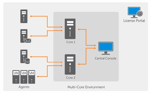
Figure 2. Multi—Core deployment architecture
Smart Agent
Smart Agent tracks the changed blocks on the disk volume and then snaps an image of the changed
blocks at a predefined interval of protection. The incremental forever block-level snapshots approach
prevents repeated copying of the same data from the protected machine to the Core. The Rapid
Recovery Smart Agent is installed on the machines that are protected by the Rapid Recovery Core.
The Smart Agent is application-aware and it detects the type of application that is installed and also the
location of the data. It automatically groups data volumes with dependency, such as databases, and then
logs them together for effective protection and rapid recovery. After the Rapid Recovery Agent software
is configured, it uses smart technology to keep track of changed blocks on the protected disk volumes.
When the snapshot is ready, it is rapidly transferred to the Core using intelligent multi-threaded, socket-
based connections. To preserve CPU bandwidth and memory on the protected machines, the smart
agent does not encrypt or deduplicate the data at the source and protected machines are paired with a
Core for protection.
DL Appliance Core
The Core is the central component of the deployment architecture. The Core stores and manages all of
the machine backups and provides core services for backup, recovery, and retention; replication, archival,
and management. The Core is a self-contained network-addressable computer that runs a 64-bit of
Microsoft Windows operating system. Your appliance performs target-based inline compression,
encryption, and deduplication of the data received from the protected machine. The Core then stores the
snapshot backups in repositories such as, Storage Area Network (SAN) or Direct Attached Storage (DAS).
The repository can also reside on internal storage within the Core. The Core is managed by accessing the
following URL from a Web browser: https://CORENAME:8006/apprecovery/admin. Internally, all core
services are accessible through REST APIs. The Core services can be accessed from within the core or
directly over the Internet from any application that can send an HTTP/HTTPS request and receive an
HTTP/HTTPS response. All API operations are performed over SSL and mutually authenticated using X.
509 v3 certificates.
Cores are paired with other cores for replication.
15

Snapshot process
A snapshot is when a base image is transferred from a protected machine to the Core. Snapshots capture
and store the state of a disk volume at a given point in time while the applications that generate the data
are still in use. In Rapid Recovery, you can force a snapshot, temporarily pause snapshots, and view lists
of current recovery points in the repository as well as delete them if needed. Recovery points are used to
restore protected machines or to mount to a local file system. The snapshots that are captured by Rapid
Recovery are done so at the block level and are application aware. This means that all open transactions
and rolling transaction logs are completed and caches are flushed to disk before creating the snapshot.
Rapid Recovery uses a low-level volume filter driver, which attaches to the mounted volumes and then
tracks all block-level changes for the next impending snapshot. Microsoft Volume Shadow Services (VSS)
is used to facilitate application crash consistent snapshots.
Replication of disaster recovery site or service provider
The replication process requires a paired source-target relationship between two cores. The source core
copies the recovery points of the protected machines and then asynchronously and continuously
transmits them to a target core at a remote disaster recovery site. The off-site location can be a
company-owned data center (self-managed core) or a third-party managed service provider’s (MSP’s)
location, or cloud environment. When replicating to a MSP, you can use built-in workflows that let you
request connections and receive automatic feedback notifications. For the initial transfer of data, you can
perform data seeding using external media, which is useful for large sets of data or sites with slow links.
In the case of a severe outage, your appliance supports failover and failback in replicated environments.
In case of a comprehensive outage, the target core in the secondary site can recover instances from
replicated protected machines and immediately commence protection on the failed-over machines.
After the primary site is restored, the replicated core can fail-back data from the recovered instances back
to protected machines at the primary site.
Recovery
Recovery can be performed in the local site or the replicated remote site. After the deployment is in
steady state with local protection and optional replication, the Core allows you to perform recovery using
Verified Recovery, Universal Recovery, or Live Recovery.
Product features
You can manage protection and recovery of critical data using the following features and functionality:
•Repository
•Deduplication in Rapid Recovery
•Encryption
•Replication
•Retention and archiving
•Virtualization And Cloud
•Alerts and Event Management
•License portal
•Web console
16

•Service Management APIs
Understanding repositories
A repository is a central location in which backup snapshot data captured from your protected
workstations and server is stored and managed. Data is saved to a repository in the form of recovery
points.
A repository can reside on different storage technologies, including Storage Area Network (SAN), Direct
Attached Storage (DAS), or Network Attached Storage (NAS).
NOTE: Store repositories for Rapid Recovery Core on primary storage devices. Speed for the storage
volume is the most critical factor. Archival storage devices such as Data Domain are not supported
due to performance limitations. Similarly, do not store repositories on NAS filers that tier to the
cloud, as these devices tend to have performance limitations when used as primary storage.
DAS offers the highest data bandwidth and fastest access rate, and is easy to implement. For optimum
results, use DAS with Redundant Array of Independent Disks (RAID) 6 storage. For more information, see
Dell Knowledge Base article 118153, “Repository Options: Direct Attached Storage, Storage Area Network
or Network Attached Storage.”
The storage location for any repository should always be in a subdirectory that you specify (for example,
E:\Repository), never in the root of a volume (for example, E:\).
The Rapid Recovery repository format uses Deduplication Volume Manager (DVM). DVM repositories
support multiple volumes, up to 255 repositories on a single Core, and the use of extents. You can create
DVM repositories on machines with Windows operating systems only. You can use this repository type
when using new Rapid Recovery installations. You can specify the size of a DVM repository upon
creation, and can add extents later.
DVM Repository features and attributes include:
• Supports recovery from Rapid Recovery 6.x archives and recovery points
• Supports storage locations on Windows OS only. Repository volume can be local (on storage
attached to the Core server), or on a storage location on a Common Internet File System (CIFS)
shared location.
• Supported storage types include Storage Area Network (SAN), Direct Attached Storage (DAS), or
Network Attached Storage (NAS)
• Requires 8GB RAM, preferably Error Checking and Correction (ECC) memory
• Requires quad core processor on Core machine (this long-standing requirement is now enforced)
• Supports multiple DVM repositories per host
• No additional services required; DVM repository uses native Core services for communication with
Core and for tracking events
• Each DVM repository supports up to 4096 repository extents (also called storage locations)
• Fixed size; DVM repository requires you to specify the repository size on a volume. The size that you
specify cannot exceed the size of the volume. Each volume you define as a storage location must
have a minimum of 1GB of free space available on it.
• Repository storage location can be a simple or dynamic disk, with speed the most important factor
• Can use standard encryption keys created and managed in the Core Console (Core-based encryption)
• Deduplicates data across the entire repository (or across encryption domains within each repository, if
encryption keys are used)
17

• Uses a dedicated, resizeable DVM deduplication cache, with a configurable storage location in Core
settings
• Optimized for writing data, storing snapshot data in a repository local to the Core, with all data
processed through the Core
• Cannot be renamed after creation
• New repositories of this type can be created using REST APIs, the Rapid Recovery Command Line
Management Utility (cmdutil.exe), or Windows PowerShell® cmdlet
When you create a DVM repository, the Rapid Recovery Core pre-allocates the storage space required for
the data and metadata in the specified location. The minimum DVM repository size is 1GB, which for
practical purposes is generally too small except for testing.
Since DVM deduplication requires a primary and secondary cache, ensure the storage space you reserve
is twice the size of your deduplication cache. For example, if you have 1.5GB reserved in the DVM
deduplication cache settings on the Core, reserve 3GB on the cache volume. The default installation path
for the cache is on the C drive. For more information, see Understanding deduplication cache and
storage locations.
You can create multiple independent repositories associated with a single Core, up to 255 DVM
repositories. Repositories can span across different storage technologies.
You can further increase the size of a DVM repository by adding new file extents or specifications. An
extended repository can contain up to 4096 extents that span across different storage technologies.
For more information on working with DVM repositories, see Managing a DVM repository.
Deduplication in Rapid Recovery
Deduplication is a data compression technique that reduces both storage requirements and network
load. The process involves physically storing unique blocks of data only once on disk. In Rapid Recovery,
when any unique data block occurs a second time within a repository, instead of storing the data again, a
virtual reference to the data is stored.
Deduplication occurs in backup snapshots captured by Rapid Recovery Core. Backup information is
deduplicated within a single repository. It cannot be deduplicated across multiple repositories.
Rapid Recovery release 6.0.2 uses target-based deduplication for all DVM repositories. In this model,
information is transferred to the DVM repository (the target), and is then deduplicated from the
repository.
For the most part, deduplication takes place inline (during the transfer of backup information).
For maximum gains, Rapid Recovery now also offers deduplication that occurs as post-processing. Post-
processing is sometimes called pass-through deduplication. Using this model, data in the repository are
compared to references in the DVM data cache. If a block of data in the repository has already been
saved, then each additional occurrence of that data is replaced with a pointer or reference to the data.
This post-processing can save space on your repository storage volume, particularly if the deduplication
cache was filled and then the cache was subsequently increased to take advantage of additional
deduplication. This type of deduplication takes place when performing a repository optimization job. This
feature is unique to DVM repositories, and is also called duplicate block reclamation.
18

For more information about the repository optimization job, see About the Repository Optimization Job.
For more information on performing this task, see Optimizing a DVM repository.
Thus, Rapid Recovery takes advantage of all types of deduplication described here: target-based
deduplication, inline deduplication, and post-processing deduplication.
For more information on where the references to unique blocks are stored for DVM repositories, see
Understanding deduplication cache and storage locations.
Understanding encryption keys
The Rapid Recovery Core can encrypt snapshot data for all volumes within any repository using
encryption keys that you define and manage from the Core Console.
Instead of encrypting the entire repository, Rapid Recovery lets you specify an encryption key for one or
more machines protected on a single Rapid Recovery Core. Each active encryption key creates an
encryption domain. There is no limit to the number of encryption keys you can create on the Core.
In a multi-tenant environment (when a single Core hosts multiple encryption domains), data is partitioned
and deduplicated within each encryption domain. As a result, Dell recommends using a single encryption
key for multiple protected machines if you want to maximize the benefits of deduplication among a set
of protected machines.
You can also share encryption keys between Cores using one of three methods. One method is to export
an encryption key as a file from one Rapid Recovery Core and import it to another Core. A second
method is to archive data secured with an encryption key, and then import that archived data into
another Rapid Recovery Core. The third method is to replicate recovery points from a protected machine
using an encryption key. After you replicate protected machines, the encryption keys used in the source
Core appear as replicated encryption keys in the target Core.
In all cases, once imported, any encryption key appears in the Core with a state of Locked. To access data
from a locked encryption key, you must unlock it. For information about importing, exporting, locking or
unlocking encryption keys, see the topic Managing encryption keys.
Key security concepts and considerations include:
• Encryption is performed using 256 Bit Advanced Encryption Standard (AES) in Cipher Block Chaining
(CBC) mode that is compliant with SHA-3.
• Deduplication operates within an encryption domain to ensure privacy.
• Encryption is performed without impact on performance.
• You can apply a single encryption key to any number of protected machines, but any protected
machine can only have one encryption key applied at a time.
• You can add, remove, import, export, modify, and delete encryption keys that are configured on the
Rapid Recovery Core.
CAUTION: Rapid Recovery takes a new snapshot whenever you apply an encryption key to a
protected machine. A new snapshot is also triggered after you disassociate an encryption key
for a protected machine.
Encryption keys generated from the Rapid Recovery Core are text files that contain four parameters, as
described in the following table:
19

Table 1. Components of an encryption key
Component Description
Name This value is equivalent to the key name given when adding a key in the Rapid
Recovery Core Console.
Key This parameter consists of 107 randomly generated English alphabetic, numeric, and
mathematical operator characters.
ID The key ID consists of 26 randomly generated upper-case and lower-case English
characters.
Comment The comment contains the text of the key description entered when the key was
created.
Replication with Rapid Recovery
This section provides conceptual and procedural information to help you understand and configure
replication in Rapid Recovery.
Replication is the process of copying recovery points from one Rapid Recovery Core and transmitting
them to another Rapid Recovery Core for disaster recovery purposes. The process requires a paired
source-target relationship between two or more Cores.
The source Core copies the recovery points of selected protected machines, and then asynchronously
and continually transmits that snapshot data to the target Core.
Unless you change the default behavior by setting a replication schedule, the Core starts a replication job
immediately after completion of every backup snapshot, checksum check, attachability check, and the
nightly jobs. For more information, see Scheduling replication.
For optimum data security, administrators usually use a target Core at a remote disaster recovery site.
You can configure outbound replication to a company-owned data center or remote disaster recovery
site (that is, a “self-managed” target Core). Or, you can configure outbound replication to a third-party
managed service provider (MSP) or cloud provider that hosts off-site backup and disaster recovery
services. When replicating to a third-party target Core, you can use built-in work flows that let you
request connections and receive automatic feedback notifications.
Replication is managed on a per-protected-machine basis. Any machine (or all machines) protected or
replicated on a source Core can be configured to replicate to a target Core.
Possible scenarios for replication include:
•Replication to a local location. The target Core is located in a local data center or on-site location,
and replication is maintained at all times. In this configuration, the loss of the Core would not prevent
a recovery.
•Replication to an off-site location. The target Core is located at an off-site disaster recovery facility
for recovery in the event of a loss.
•Mutual replication. Two data centers in two different locations each contain a Core and are
protecting machines and serving as the off-site disaster recovery backup for each other. In this
scenario, each Core replicates the protected machines to the Core that is located in the other data
center.
•Hosted and cloud replication. Rapid Recovery MSP partners maintain multiple target Cores in a data
center or a public cloud. On each of these Cores, the MSP partner lets one or more of their customers
replicate recovery points from a source Core on the customer’s site to the MSP’s target Core for a fee.
20
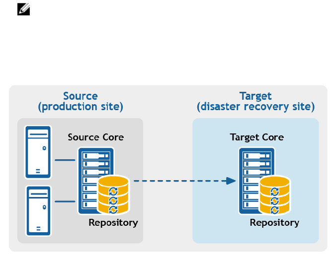
NOTE: In this scenario, customers only have access to their own data.
Possible replication configurations include:
•Point-to-point replication. Replicates one or more protected machines from a single source Core to
a single target Core.
Figure 3. Point-to-point replication configuration
•Multipoint-to-point replication. Replicates protected machines from multiple source Cores to a
single target Core.
21
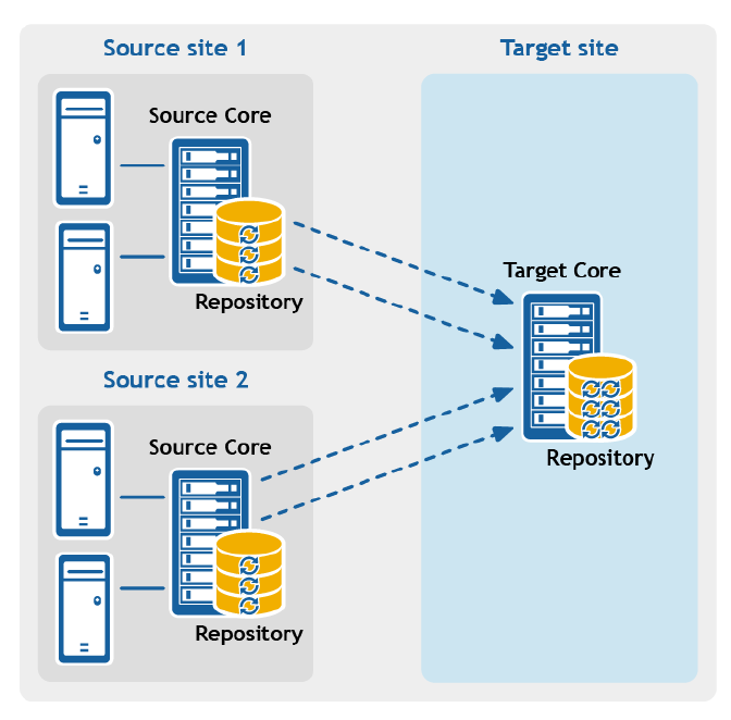
Figure 4. Multipoint-to-point replication configuration
•Point-to-multipoint replication. Replicates one or more protected machines from a single source
Core to more than one target Core.
22
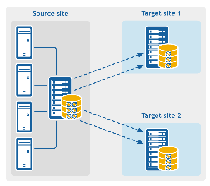
Figure 5. Point-to-multipoint replication configuration
•Multi-hop replication. Replicates one or more protected machines from one target Core to another
target Core, producing additional failover or recovery options on the replicated Core.
23
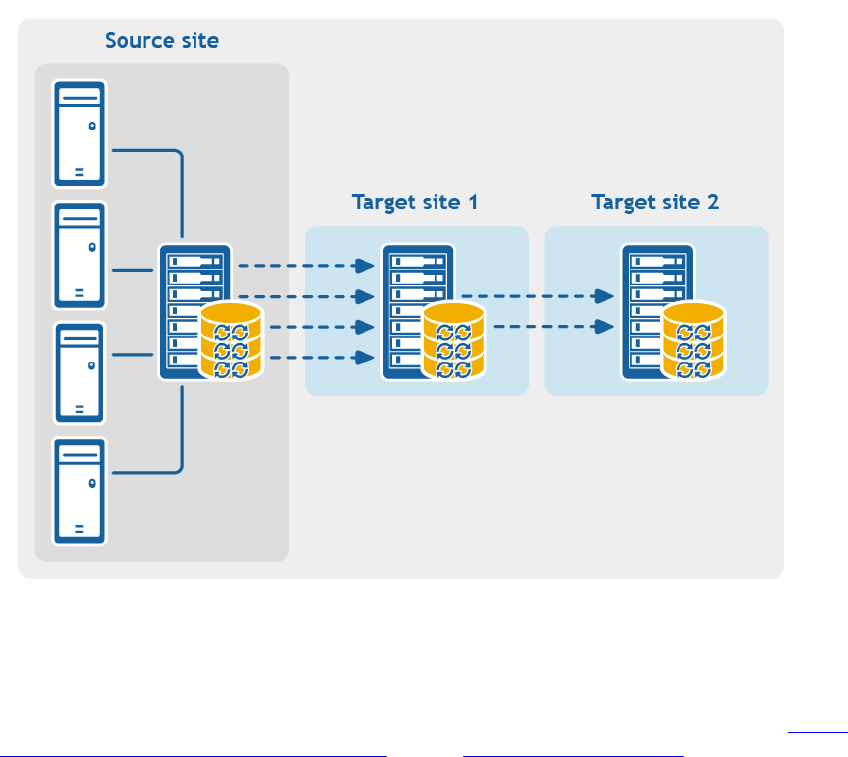
Figure 6. Multi-hop replication configuration
If using Dell Data Protection backup appliances such as the DL1x00 or DL4x00 series, the target Core to
which you replicate must have a valid software license configured. These hardware appliances include a
replication target license with purchase. Check for your license key in the welcome email message you
received when purchased the appliance. For assistance, visit the Licensing Assistance website at https://
support.software.dell.com/licensing-assistance or email license@software.dell.com.
Retention and archiving
In your appliance, backup and retention policies are flexible and, therefore, easily configurable. The ability
to tailor retention polices to the needs of an organization not only helps to meet compliance
requirements, but does so without compromising on RTO.
Retention policies enforce the periods of time in which backups are stored on short-term (fast and
expensive) media. Sometimes certain business and technical requirements mandate extended retention
of these backups, but use of fast storage is cost prohibitive. Therefore, this requirement creates a need
for long-term (slow and cheap) storage. Businesses often use long-term storage for archiving both
compliance and non-compliance data. The archive feature supports extended retentions for compliance
and non-compliance data, it can also be used for seeding replication data to a target core.
24
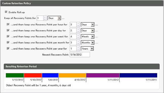
Figure 7. Custom retention policy
In your appliance, retention policies can be customized to specify the length of time a backup recovery
point is maintained. As the age of the recovery points approaches the end of their retention period, the
recovery points age out and are removed from the retention pool. Typically, this process becomes
inefficient and eventually fails as the amount of data and the period of retention start grows rapidly. Your
appliance solves the big data problem by managing the retention of large amounts of data with complex
retention policies and performing rollup operations for aging data using efficient metadata operations.
Backups can be performed with an interval of a few minutes. As these backups age over days, months,
and years, retention policies manage the aging and deletion of old backups. A simple waterfall method
defines the aging process. The levels within the waterfall are defined in minutes, hours, days, weeks,
months, and years. The retention policy is enforced by the nightly rollup process.
For long-term archiving, your appliance provides the ability to create an archive of the source or target
core on any removable media. The archive is internally optimized and all data in the archive is
compressed, encrypted, and deduplicated. If the total size of the archive is larger than the space available
on the removable media, the archive spans across multiple devices based on the available space on the
media. The archive also can be locked with a passphrase. Recovery from an archive does not require a
new core; any core can ingest the archive and recover data if the administrator has the passphrase and
the encryption keys.
Virtualization and cloud
The Core is cloud-ready, which allows you to leverage the compute capacity of the cloud for recovery.
Your appliance can export any protected or replicated machine to a virtual machine, such as licensed
versions of VMware or Hyper-V. You can perform a one-time virtual export, or you can establish a virtual
standby VM by establishing a continuous virtual export. With continuous exports, the virtual machine is
incrementally updated after every snapshot. The incremental updates are very fast and provide standby
clones that are ready to be powered up with a click of a button. The supported virtual machine export
types are VMware Workstation/Server on a folder; direct export to a vSphere/VMware ESX(i) host; export
to Oracle VirtualBox; and export to Microsoft Hyper-V Server on Windows Server 2008 (x64), 2008 R2,
2012 (x64), and 2012 R2 (including support for Hyper-V generation 2 VMs)
25
Additionally, you can now archive your repository data to the cloud using Microsoft Azure, Amazon S3,
Rackspace Cloud Block Storage, or other OpenStack-based cloud services.
Alerts and event management
In addition to HTTP REST API, your appliance also includes an extensive set of features for event logging
and notification using e-mail, Syslog, or Windows Event Log. email notifications can be used to alert users
or groups of the health or status of different events in response to an alert. The Syslog and Windows
Event Log methods are used for centralized logging to a repository in multi-operating system
environment. In Windows-only environments, only the Windows Event Log is used.
License portal
The License Portal provides easy-to-use tools for managing license entitlements. You can download,
activate, view, and manage license keys and create a company profile to track your license assets.
Additionally, the portal enables service providers and re-sellers to track and manage their customer
licenses.
Web console
Your appliance features a new web-based central console that manages distributed cores from one
central location. MSPs and enterprise customers with multiple distributed cores can deploy the central
console to get a unified view for central management. The central console provides the ability to
organize the managed cores in hierarchical organizational units. These organizational units can represent
business units, locations, or customers for MSPs with role-based access. The central console can also run
reports across managed cores.
Service management APIs
Your appliance comes bundled with a service management API and provides programmatic access to all
of the functionality available through the Central Management Console. The service management API is a
REST API. All the API operations are performed over SSL and are mutually authenticated using X.509 v3
certificates. The management service can be accessed from within the environment or directly over the
Internet from any application that can send and receive an HTTPS request and response. This approach
facilitates easy integration with any web application such as relationship management methodology
(RMM) tools or billing systems. Also included is an SDK client for PowerShell scripting.
26

2
Working with the DL Appliance Core
Understanding the Rapid Recovery Core Console
This section describes the different elements of the Rapid Recovery Core Console user interface (UI).
Accessing the Rapid Recovery Core Console
Complete the following steps to access the Rapid Recovery Core Console.
• Perform one of the following to access the Rapid Recovery Core Console:
a. Log in locally to your Rapid Recovery Core server, and then double click the Core Console icon.
b. Or, type one of the following URLs in your web browser:
– https://<yourCoreServerName>:8006/apprecovery/admin/ or
– https://<yourCoreServerIPaddress>:8006/apprecovery/admin/
NOTE: Because the Rapid Recovery Core Console UI depends JavaScript, the web browser
you use to access the Core Console must have JavaScript enabled.
If you have changed the default port for the Rapid Recovery service, update the port in the
preceding URL accordingly.
Understanding the Quick Start Guide
The Quick Start Guide is a feature that provides you with a guided flow of suggested tasks for configuring
and using Rapid Recovery Core.
The Quick Start Guide appears automatically the first time you upgrade to or install the Rapid Recovery
Core and navigate to the Core Console. Click Start Guide on the Welcome page of the guide to see the
various suggested configuration tasks. Navigate through the guide using the Skip Step and Back options.
When you have seen the last suggested task, click Finish to close the guide.
You can launch the Quick Start Guide again at any time from the Help menu in the Core Console. You
can also choose to hide the Welcome page in the Quick Start Guide.
Unless you hide it, the Quick Start Guide reappears each time you log in to the Rapid Recovery Core
Console and access the Home page. For more information, see Hiding the Quick Start Guide.
You are not required to perform the steps suggested by the guide. You can simply view the suggested
tasks, navigating through them using the Skip Step and Back options. Optionally, to hide the guide at any
point, click Exit Guide.
If you choose to perform any configuration tasks suggested by the Quick Start Guide, follow the prompts
indicated in any step of the guide, and the appropriate wizard or relevant area in the user interface
appears. Procedures to complete each task suggested by the guide is described in this document, as
indicated in the table below.
27

NOTE: Not all configuration tasks suggested by the Quick Start Guide are required for all users. You
must understand which tasks you want to accomplish for your specific needs.
The Quick Start Guide addresses the following configuration tasks:
Table 2. Quick Start Guide configuration tasks
Function Short Description Result of Selecting Task, Link to Procedure
Protection Protecting a single machine,
protecting a server cluster,
or protecting multiple
machines using bulk protect
Click Protect or select Protect Machine from the drop-
down menu to open the Protect Machine Wizard. For
information on completing the Protect Machine Wizard,
see Protecting a machine.
Select Protect Cluster from the drop-down menu to open
the Connect to Cluster dialog box. For more information
on protecting a cluster, see Protecting a cluster.
Select Bulk Protect from the drop-down menu to open
the Protect Multiple Machines Wizard. For information on
completing the Protect Multiple Machines Wizard, see
About protecting multiple machines.
Replication Setting up replication from a
primary (source) Core to a
secondary (target) Core
Click Replication to open the Replication page. Prompts
you to add a target Core using the Replication Wizard. For
information on using the Replication Wizard to set up
replication on a self-managed Core, see Replicating to a
self-managed target Core. For general information on
replication, see Configuring replication.
Virtual Export Performing a one-time
export or establishing
continual export from a
protected machine to a
virtual machine
Click Export to perform an export of data from your
protected machine to a virtual machine. You can either
perform a one-time export, or set up virtual standby for
continual export to a VM. For information on virtual
exports, see About exporting to virtual machines with
Rapid Recovery.
Configuratio
n
Allows you to set up
additional configuration for
the Rapid Recovery Core
Click More to see additional functions you can configure
or manage. Functions includes archives; mounts; boot
CDs; repositories; encryption keys; cloud accounts; file
search; retention policies; notifications; reports; logs; and
more.
Configuratio
n: Encryption
Adding or importing
encryption keys that you
can use for one or more
protected machines
Click Encryption keys to manage security for protected
data by adding or importing encryption keys. You can
apply encryption keys to one or more protected machines.
Encryption is described in the topic Understanding
encryption keys.
Configuratio
n:
Notifications
Setting up notifications for
events, warnings and alerts
Click Events to specify notification groups for events,
warnings, and alerts. To send these by email, you must
also establish SMTP server settings. For more information
on managing events, see the topic Events, including the
topics Configuring notification groups and Configuring an
email server.
Configuratio
n: Retention
Viewing or changing the—
default retention policy for
the Core
Click Retention Policy to open the Retention Policy page
for the Core. From here you can define how long to keep
a recovery point before rolling it up. For conceptual
information about retention policies, see the topic
28

Function Short Description Result of Selecting Task, Link to Procedure
Managing aging data. For procedural information, see
Managing retention policies.
Restore Restoring data from a
recovery point on the Core
Click Restore to open the Restore Machine Wizard. For
information on restoring data, see the topic About
restoring volumes from a recovery point.
Hiding the Quick Start Guide
The Quick Start Guide appears automatically the first time you upgrade to or install the Rapid Recovery
Core.
It also appears when you select Quick Start Guide from the Help drop-down menu, and each time you
access the Home page on the Core Console.
Use the procedure below to hide the Quick Start Guide.
• From the Rapid Recovery Core Console, if you are viewing the Welcome page of the Quick Start
Guide, do the following:
– If you want to hide the Welcome page of the Quick Start Guide, select Don't show again.
NOTE: This option will hide the Welcome page the next time the Start Guide is opened, and
every time, until you upgrade the Rapid Recovery Core.
If you choose to hide this page, and want to access advanced options in the future, then
select Back in the wizard to see this hidden page.
– If you want to hide the Quick Start Guide for this session, then click Close.
The Quick Start Guide closes. The next time you access the Home page on the Core Console, the
Quick Start Guide reappears.
You can also open the Quick Start Guide from the Help menu.
• From any page in the Quick Start Guide click Exit Guide.
The Quick Start Guide closes. If you select this option, you can still open the Quick Start Guide from
the Help menu.
Navigating the Rapid Recovery Core Console
When you log into the Core Console, and any time you click the Home icon, the Home page
appears. The Home page gives you a view of your Rapid Recovery Core, with two options. In the main
viewing area, the default content is the new Core dashboard, which displays a set of real-time reports on
your system. Default dashboard reports include recent transfer job status, per machine transfer, a
repository overview, and connectivity state for protected, replicated, and recovery points-only machines.
Or you can switch to the classic Summary Tables view. In this view, the title of the page shows the display
name of your Rapid Recovery Core, and you can see summary tables showing protected machines,
repositories, and recent alerts. For more information, see Understanding the Home page (summary tables
view) and Understanding the Core dashboard, respectively.
On the Home page (and on every page in the Core Console), the left navigation area shows the items
that are protected on your Core. You can navigate to other pages in the UI by doing one of the following:
• Clicking the corresponding icon from the icon bar in the left navigation area. The options accessible
from the icon bar include Replication, Virtual Standby, Events, Settings, and More.
29

• Expanding the (More) menu on the icon bar, and then selecting a destination
• Clicking a button or menu option from the button bar. Buttons include Protect, Restore, Archive, and
Replicate.
When you select an item from the left navigation area, the focus of the Core Console changes to display
summary information about that item. For example, if you click the name of a protected machine, the
Core console displays information about that machine only, rather than the Core. In this example, the
display name of the protected machine appears as the title of the page. A submenu appears to the right,
letting you view specific information about the protected machine. The menu options include: Summary,
Recovery Points, Events, Settings, Reports, and More.
To return to viewing information about the Core, including dashboard reports, or a summary view of
multiple protected or replicated machines, click on the Home icon on the top left of the UI. On the
Home page, you can toggle between the dashboard view and the summary page view by clicking the red
link at the top right of the page.
You can use the title at the top of the Core Console to provide context for the information you are
viewing in the Core. For example:
• Any time you see the display name or IP address of the Core as the page title, you are viewing
summary information about the Core.
• If the title is Dashboard, you are viewing the Core dashboard.
• If you see the display name or IP address of a protected machine, or a Summary pane at the top of a
page, you are viewing information about a single machine protected by or replicated in the Core.
• If you see the title Protected Machines, you are viewing information about all of the machines
protected in the Rapid Recovery Core.
• If you see the title Machines replicated from..., you are viewing information about all of the machines
replicated in the Rapid Recovery Core.
• If you see the page title Recovery Points Only, you are viewing information about all of the recover
points-only machines on this Core.
For information about the features and functions available from each page, see the appropriate section
below.
For more information about viewing protected machines, see Viewing the Protected Machines menu. For
more information on managing protected machines, see Managing protected machines.
For more information about viewing replicated machines, see Viewing incoming and outgoing
replication.
For more information about viewing recovery-points only machines, see Viewing the Recovery Points
Only menu
Understanding the left navigation area
The left navigation area of the Core Console appears on the left side of that user interface. The contents
of this navigation area may differ based on the type of objects protected in your Rapid Recovery Core.
The left navigation area always contains the following:
•Icon bar. For navigation among the main pages of the Core Console.
30

•Text filter. The text filter is a text field that lets you filter the items displayed in the various menus that
appear below it. Clicking the arrow to the right of the text filter expands and collapses each of the
menus appearing below it.
Following these elements, the left navigation area typically displays menus to help you navigate, filter, and
view the objects protected on your Core. This includes protected machines, replicated machines, and so
on.
Each menu is context-sensitive; that is, each menu only appears in the Core Console if it is relevant. For
example, if you protect at least one machine, the Protected Machines menu appears, and so on.
For more information, see the left navigation area tables in Viewing the Core Console user interface.
Viewing the Rapid Recovery Core Console Home page
Each time you log into the Rapid Recovery Core Console, or each time you click on the Home icon
in the icon bar, the Home page appears.
The Home page of the Core Console offers a new dashboard view, and the familiar summary tables
view. The dashboard is the default view.
You can toggle between views on the Home page by clicking the red link at the top right of the Home
page.
From the Home page, and every other page of the Core Console, you can navigate to the functions you
want by using the left navigation area.
For more information, see the following topics:
•Understanding the left navigation area
•Understanding the Core dashboard
•Understanding the Home page (summary tables view)
Understanding the Home page (summary tables view)
The Home page is only applicable to the Core. In the dashboard view, it shows real-time graphical
reports. When you switch to the summary tables view, the Home page displays all of the machines the
Core protects or replicates, the repositories associated with your Core, and alerts for machines on this
Core.
The view of each pane on the Home page can be expanded or contracted. For example, if you click the
(contract view) icon at the top right-hand side of the Protected Machines pane, the view of
protected machines contracts, and only the name of the pane is visible. To expand the view to see all
protected machines again, click the (expand view) icon.
The following table describes the various elements on the Home page when in the summary tables view.
Table 3. Home page options
UI Element Description
Protected
Machines
The Protected Machines pane lists the machines that this Core protects. This pane
appears regardless of whether any machines have been added to your Core for
protection.
31

UI Element Description
This section includes the following information for each protected machine:
•Machine type. An icon shows whether the machine is a physical machine, virtual
machine, or a protected cluster.
•Status. Colored circles in the Status column show whether the protected machine
is accessible, paused, or offline and unreachable.
•Display Name. The display name or IP address of the protected machine.
•Repository Name. The name of the repository storing the recovery points for that
machine.
•Last Snapshot. The date and time on which Rapid Recovery took the most recent
recovery point snapshot for that machine.
•Recovery Points. The number of recovery points stored in the repository and
space usage for each protected machine.
•Version. The version of the Rapid Recovery Agent software installed on that
machine.
If you click on a specific machine name shown in this pane, a Summary page appears,
showing summary information for the selected machine. For more information on
what you can accomplish on the Summary page, see Viewing summary information
for a protected machine.
Replicated
Machines
The Replicated Machines pane lists any machines that this Core replicates from
another Core. This pane does not appear unless your Core replicates machines from
another Core.
This section includes the following information for each replicated machine:
•Machine type. An icon shows whether the machine is a physical machine, virtual
machine, or a protected cluster.
•Status. Colored circles in the Status column show whether the replicated machine
is accessible, paused, or offline and unreachable.
•Display Name. The display name or IP address of the replicated machine.
•Replication Name. The display name of the originating source Core for any
machines you replicate on this target Core. You can define this name when setting
up replication.
•Repository Name. The name of the repository storing the recovery points for that
machine.
•Last Replicated Snapshot. The date and time on which Rapid Recovery took the
most recent replica of the original protected machine.
•Recovery Points. The number of recovery points stored in the repository and
space usage for each replicated machine.
•Version. The version of the Rapid Recovery Agent software installed on that
machine.
If you click on a specific machine name shown in this pane, the Summary page
appears, showing summary information for that replicated machine.
Recovery Points
Only Machines
The Recovery Points Only Machines pane lists any machines that were removed from
protection or replication, if the recovery points have been retained. These machines
can be used for file-level recovery, but cannot be used for bare metal restore, for
restoring entire volumes, or for adding snapshot data. This pane does not appear
unless you have any machines that meet this definition.
32

UI Element Description
This section includes the following information for each recovery points only
machine:
•Machine type. An icon shows whether the machine is a physical machine, virtual
machine, or a protected cluster.
•Status. Colored circles in the Status column show whether the recovery points
only machine is accessible, paused, or offline and unreachable.
•Display Name. The display name or IP address of the machine for which you kept
recovery points.
•Repository Name. The name of the repository storing the remaining recovery
points for that machine.
•Recovery Points. The number of recovery points stored in the repository and
space usage for each recovery points-only machine.
If you click on a specific machine name shown in this pane, the Summary page
appears for this recovery points only machine.
DVM
Repositories
This pane appears for the DL1000, regardless of whether any DVM repositories have
been created. This pane does not appear unless your Core has one or more DVM
repository.
It includes the following information for each DVM repository:
•Type. An icon depicts a repository.
•Status. Colored circles in the Status column show whether the repository is
mounted and can accept recovery point transfers, or is unreachable, or in an error
state.
•Repository Name. The display name of the repository.
•Space Usage.The total amount of space used in the repository, and the size of the
storage volume or extent.
•Protected Data. The amount of used space in the repository.
•Machines. The number of machines for which the repository stores recovery
points.
•Recovery Points. The number of recovery points stored in the repository.
•Compression Ratio. The rate at which the repository compresses the protected
data to save space.
For more information, see Understanding repositories.
Alerts This section lists the important alerts for the Core and every machine it protects. The
section includes the following information:
•Icons. The column of icons indicates the nature of the alert. These include
informational messages, errors
•Date. Displays the date and time of when Rapid Recovery issued the alert.
•Message. Describes the alert.
You can also see these details on the Core Events page. For more information, see
Viewing events using tasks, alerts, and journal.
Understanding the Core dashboard
The Core dashboard displays of a set of real-time graphical reports of data relevant to your Core and the
machines you protect. The dashboard includes the following reports:
33

•Transfer Job. This report shows all snapshot data transfers (including base images and incremental
snapshots) that completed in the last 24 hours. Snapshots include base images and incremental
snapshots. This dashboard report appears as a circle graph.
•Transfer Job per Machine. This job shows, by protected machine, the number of successful and failed
transfer jobs in the last 24 hours. This dashboard report appears as a line graph.
•Repository. This report shows the repositories associated with your Core. It shows the number of
repositories, how many machines are protected in each, the number of recovery points and the
percentage of compression or deduplication. This report is refreshed every minute.
•Machine Connectivity. This report shows the connectivity state of machines protected and replicated
on your Core. It also shows connectivity for data on recovery points-only machine .
You can collapse or expand the view of any reports on the dashboard by clicking the up or down arrow in
the header of the report. Some dashboard reports (machine connectivity and repository) have a plus sign
next to the arrow, from which you can add another protected machine or another repository,
respectively.
You can also drag and drop to move the location of one of the reports elsewhere on the dashboard, to
order the reports in a manner most effective for your use.
Viewing the Protected Machines menu
In the Rapid Recovery user interface, a Protected Machines menu appears in the left navigation area. As
with all menu labels in the navigation area, the label for this menu appears in all upper-case letters. By
default, this menu is fully expanded, and shows a list of any machines that are protected by this Core. If
you have any server clusters protected, then they are included in this list.
You can collapse or expand the view for protected machines and server clusters in your Core by clicking
the arrow on the left side of this menu.
The Protected Machines menu includes a drop-down menu on the right side which lists functions that
can be performed on all protected machines. Click the arrow to the right of Protected Machines to see
the menu and to perform any of the following:
• Force an incremental snapshot for all machines
• Force a base image for all machines
• Pause protection for all machines (if protection is active)
• Resume protection for all machines (if protection is paused)
• Refresh metadata for all protected machines
• Remove all machines from protection on the Core
Each machine listed under the Protected Machines menu also has a drop-down menu that controls
functions only for that machine. From the drop-down menu for any machine, you can perform the
following:
• Force an incremental snapshot for the selected machine
• Pause protection for the selected machine (if protection is active)
• Resume protection (if protection is paused)
• Refresh metadata
• Remove the selected machine from protection on the Core
• Navigate to the Summary page for the selected machine
• Navigate to the Recovery Points page for the selected machine
34

• Navigate to the Events page for the selected machine
• Navigate to the Settings page for the selected machine
• Generate reports specific to that machine
• Access more functions specific to the selected machine, including system information, mounts,
retention policy, notifications, or a machine-specific log
• Create a custom label that displays in the Protected Machines list
If you are managing server clusters from the Rapid Recovery Core, the cluster also appears in the left
navigation menu. From the drop-down menu for any cluster, you can also:
• Navigate to the Protected Nodes page for the selected cluster
If you click the arrow to the left of the Protected Machines menu, the list of protected machines and
server clusters contracts, and no machines are listed. Clicking again on this arrow causes the list of
machines to expand again.
Clicking any machine name in the Protected Machines menu opens the Summary page for that machine.
For more information on what you can accomplish on the Summary page, see Viewing summary
information for a protected machine.
Finally, clicking directly on the Protected Machines menu causes the Protected Machines page to appear
in the main content area, with a single pane showing protected machines on this Core. For more
information on what you can accomplish on the Protected Machines pane of the Protected Machines
page, see Viewing the Protected Machines pane.
NOTE: From the Protected Machines page, you can return to a view from the Core perspective by
clicking the Home icon in the icon bar.
Viewing summary information for a protected machine
When you click the name of a protected machine in the Core Console, the Summary page appears. On
this page, at minimum, is a Summary pane, and a Volumes pane. If a machine is added to replication, a
Replication pane also appears.
If you have one or more protected Exchange servers, you will also see an Exchange Server Information
pane that contains information about your protected Exchange server.
If you have one or more protected SQL servers, you will also see a SQL Server Information pane that
contains information about your protected SQL servers.
At the top of his page is a menu of actions you can perform on the protected machine. Below it, at
minimum, appears a Summary pane, and a Volumes pane. If a machine is added to replication, a
Replication pane also appears.
When displaying information for a protected machine—on the Summary page and all other views—there
is a menu at the top of the page with functions you can perform. This menu appears immediately below
the name of the protected machine.
35

Related links
Viewing the Summary pane
Viewing Volumes on a protected machine
Viewing replication information
Viewing the Exchange Server Information pane
Viewing the SQL Server Information pane
Viewing the Summary pane
The Summary pane contains summary information about the protected machine, including the host
name, date and time of the last snapshot, date and time of the next scheduled snapshot, encryption key
information, and version information for the Rapid Recovery Agent software. There is also a link to a
detailed System Information page for the machine.
Viewing Volumes on a protected machine
For any protected machine, from the Summary page, in the Volumes pane, you can perform the
following actions for any of the volumes listed:
• Set or modify a protection schedule for a selected volume. Protection schedules are typically
established when you first protect a machine. For more information about modifying a protection
schedule, see Modifying protection schedules.
• Force a base image or snapshot. Snapshots typically occur based on the protection schedule.
However, at any time, you can force a base image or an incremental snapshot for selected volumes.
For more information, see Forcing a snapshot.
Viewing replication information
The Replication pane contains summary information about the replicated machine, including the
replication name, the state of replication, progress, and available space.
Viewing the Exchange Server Information pane
The Exchange Server Information pane appears only for protected machines that are Exchange servers.
This pane contains summary information about the protected Exchange server, including the installed
version of Microsoft Exchange, the path in which Exchange is installed, and the path defined for
Exchange mailbox data.
The Mail Stores grid shows the Exchange Database (EDB) name, the path of the EDB file, the path in
which the log files are stored, the log prefix, the system path, the Database Availability Group (DAG), and
the mail store type.
Viewing the SQL Server Information pane
The SQL Server Information pane appears only for protected machines that are SQL Servers.
This pane contains summary information about the protected SQL Servers. You can expand the database
information to see detail for each table in the database. You can also see the database or table name and
the database path.
Viewing recovery points for a machine
The Recovery Points page shows a list of the recovery points collected for that protected machine as well
as pertinent machine and repository data. On this page, you can mount, export, and restore specific
recovery points, as well as delete recovery points.
36

The page is divided into two panes: Recovery Points Summary and Recovery Points. The Summary pane
does not include any actionable links. It displays the following data for the machine.
Table 4. Recovery Points Summary pane data
UI Element Description
Total Recovery
Points
The number of recovery points collected for this particular protected machine.
Total Protected
Data
The amount of data from the protected machine that is stored in the repository.
Repository The name of the repository in which Rapid Recovery stores the recovery points for this
protected machine.
Repository
Status
The progress bar displays the percentage of the total space used in the repository. The
amount of data used and the total size of the repository appear below the progress
bar.
For more information, see Viewing the Protected Machines pane.
Viewing events for a protected machine
On the Events page, you can view the jobs that occurred or are in progress for the protected machine
you selected. Buttons at the top of the page let you navigate to lists of jobs in each of the three
categories of activities:
•Tasks. A job that the Rapid Recovery must perform to operate successfully.
•Alerts. A notification related to a task or event that includes errors and warning.
•Journal. A composite of all protected machine tasks and alerts.
The following table includes descriptions of each element on the Events page.
Table 5. Events page elements
UI Element Description
Search keyword Lets you search for a specific item within each category. Available for tasks only.
From To narrow your results, you can enter a date at which to begin searching. Available for
tasks only.
To To narrow your results, you can enter a date at which to stop searching. Available for
tasks only.
Status icons Each icon represents a different job status. For alerts and tasks, clicking one of the
icons lets you filter the list by that status, essentially generating a report. Clicking the
icon a second time removes the filter for that status. You can filter by more than one
status. Statuses include:
•Active. A job that is in progress.
•Queued. A job that is waiting for another job to complete before it can initiate.
•Waiting. A job waiting for your approval or completion, such as a seed drive. (For
more information about seed drives, see Replication.)
•Complete. A job that completed successfully.
•Failed. A job that failed and did not complete.
37

UI Element Description
Service icon This button adds services jobs to the list of jobs. When you click this icon, a smaller
service icon appears on each status icon, which lets you filter by service jobs that have
those statuses (if any exist). Examples of services jobs include deleting index files or
removing a machine from protection.
Export type
drop-down list
The drop-down list includes the formats to which you can export the event report.
Available for tasks only. It includes the following formats:
• PDF
• HTML
• CSV
• XLS
• XLSX
(Export
icon)
Converts the event report to the format you selected. Available for tasks only.
Page selection Event reports can include several jobs across multiple pages. The numbers and arrows
at the bottom of the Events page let you navigate the additional pages of the report.
The Events page displays all events in a table. The following table lists the information shown for each
item.
Table 6. Detailed information for the Event summary table
UI Element Description
Status Shows the status for the task, alert, or journal item. Available for alerts or journal items,
click the header to filter the results by status.
Name Name is available for tasks only. This text field lists the task type that completed for
this protected machine. Examples include transfer of volumes, maintaining repository,
rolling up, performing mountability checks, performing checksum checks, and so on.
Start Time Available for tasks, alerts, and journal items. Shows the date and time when the job or
task began.
End Time Available for tasks only. Shows the date and time when the task completed.
Job
Details
Available for tasks only. Opens the Monitor Active Task dialog box, so you can view
details of the specific job or task. These details include an ID for the job, rate at which
the core transferred data (if relevant), elapsed time for the job to complete, total work
in amount of gigabytes, and any child tasks associated with the job.
Message Available for alerts and journal items. This text field provides a descriptive message of
the alert or journal item.
Viewing reports for a protected machine
The Reports drop-down menu lets you generate reports on demand for the selected protected
machine.
38

The Job report provides a report on the status of successful jobs and failed jobs for the selected machine.
Failed jobs can be further viewed in a Failure report. For more information on this report type, see
Understanding the Job report.
The Failure report provides information on failed and canceled Core jobs for the specified machine. For
more information on this report type, see Understanding the Failure report.
For more information about generating these reports, see Generating a Core report on demand.
Viewing replicated machines from the navigation menu
If your Core replicates machines from another Rapid Recovery Core, the display name of the source Core
appears as a collapsible menu in the left navigation of the Core Console. As with all menu labels in the
navigation area, this replicated machines menu name appears in all upper-case letters, below the
Protected Machines menu. By default, the replicated machines menu is fully expanded, and lists all
machines originating from that source Core that are replicated on your target Core.
You can collapse or expand the view of replicated machines from that source Core by clicking the arrow
on the left side of this menu.
Each replicated machines menu includes a drop-down menu on the right side, which includes functions
you can perform simultaneously on all of the replicated machines originating from that Core. Click the
arrow to the right of replicated machines menu to see a drop-down list of functions you can perform.
These actions include the following:
• Pause replication. If replication is currently active, it stops the action until you resume it.
• Resume replication. If replication has been paused, it begins replicating again.
• Force replication. Replicates on demand, rather than at a scheduled time.
• Remove replication. Removes the replication relationship between the source core and your target
core. Optionally, you can delete the recovery points stored in this Core. For more information, see
Removing replication.
Clicking directly on name of the source Core in the navigation menu causes the Machines replicated
from [Source Core Name] page to appear in the main content area. For more information on what you
can accomplish on that page, see Viewing incoming and outgoing replication.
Related links
Pausing and resuming replication
Forcing replication
Removing replication
Viewing the Recovery Points Only menu
The Recovery Points Only menu appears in the left navigation area if one of the following is true:
• if your Rapid Recovery Core retains some recovery points from a machine that was previously
protected
• if you removed replication but retained the recovery points.
As with all menu labels in the navigation area, the label for this menu appears in all upper-case letters.
39

You can collapse or expand the view of recovery points-only machines by clicking the arrow on the left
side of this menu.
The menu includes a drop-down menu on the right side which lists functions that can be performed on
all recovery points-only machines simultaneously. In this case, the only function you can perform is to
remove recovery points from the Core.
CAUTION: This action removes all of the recovery points-only machines in your Rapid Recovery
Core, permanently deleting them and precluding you from restoring information from those
recovery points from this Core.
Viewing the Custom Groups menu
The custom groups menu appears in the left navigation area only if you have defined one or more
custom groups. As with all menu labels in the navigation area, the label for this menu appears in all
upper-case letters.
You can collapse or expand the view of items in this menu by clicking the arrow on its left side.
The custom groups menu includes a drop-down menu on the right side which lists functions that can be
performed simultaneously on all of the like items in that group.
For more information, see Understanding custom groups.
Using the Error dialog box
When an error occurs in the Rapid RecoveryRapid Recovery Core Console user interface, such as trying
to enter an invalid parameter, an Error dialog box appears. The dialog box typically indicates the cause of
the error, includes some links to provide more information about the error, and includes a Close button.
You must close the Error dialog box before you continue, but you may want to view more information
about the error.
In the Error dialog box, choose from the following options:
User interface errors that cause the Error dialog box to appear are not tracked in Rapid Recovery events
tab, since they are simply validation or data entry errors. However, when you click the Search Knowledge
Base option for any error, then the URL link provided for that error is recorded to the
CoreAppRecovery.log file. You can search the log for the text string “KB article url generated” to see the
URL for each error that was viewed in a browser. For more information on downloading or viewing Core
error logs, see the topics Downloading and viewing the Core log file or Accessing Core logs, respectively.
Core settings
This section describes how to manage and change the settings for your Rapid Recovery Core from the
Settings icon.
Rapid Recovery Core settings
The Rapid Recovery Core settings are configured by default for optimum performance for most users.
These settings affect the performance of the Rapid Recovery Core, or in some cases the display of
40

information in the Rapid Recovery Core Console. From the icon bar, click (Settings) to access Core
settings. A list of all Core settings appears on the left. You can click on the title for any of the settings
from this list to jump to the full configuration for that setting on the right. Or you can scroll down
through all the Core settings on the right to see all configuration options. For more information, see
Rapid Recovery Core settings.
You can also access Core tools such as viewing a summary of system information, or downloading Core
log files. For more information, see Core-level tools.
The comprehensive set of Rapid Recovery Core settings that you can configure is described in the
following table.
Table 7. Rapid Recovery Core configurable settings
Configuration
Setting Description
Backup and
restore Core
configuration
Rapid Recovery lets you back up Core configuration settings to an XML file. If you
have a backup file, you can use it to restore or migrate Core settings.
For more information about backing up and restoring Core settings, see Backing up
and restoring Core settings.
General General settings include configuration options that apply generally to the Rapid
Recovery Core, including display options and ports for the web server and for the
Rapid Recovery service.
For more information about the general settings for Rapid Recovery Core, including
how to configure these settings, see Configuring Core general settings.
Updates Update settings controls aspects of the Automatic Update feature, which checks for
updated versions of Rapid Recovery software.
For more information about settings for updating the Rapid Recovery Core, including
how to configure these settings, see Configuring update settings.
Nightly jobs Nightly jobs settings are automated tasks which the Core performs on a daily basis.
You can configure the time the jobs begin and which jobs are performed. Dell
recommends scheduling the jobs outside of normal business hours to reduce load on
the system when demand for resources is high.
For more information, see Understanding nightly jobs, Configuring nightly jobs for the
Core, and Customizing nightly jobs for a protected machine.
Transfer queue Transfer queue settings control the number of times transfer operations are attempted
if jobs fail due to unavailability of resources. You can establish the maximum number
of concurrent transfers and the maximum number of retries for transferring data.
For more information about transfer queue settings, see Modifying transfer queue
settings.
Client timeout Client timeout settings determine the length of time before that specific connection
requests or read and write operations should be attempted before timing out.
For more information about client timeout settings, see Adjusting client timeout
settings.
41

Configuration
Setting Description
DVM
Deduplication
cache
Deduplication ensures that unique blocks of information are stored only once in your
repository, creating references to repeated data blocks. The references are stored in a
deduplication cache. If encryption keys are used, then deduplication occurs within
each encryption domain.
DVM deduplication cache settings let you configure the size and specify the locations
for the primary and secondary cache, as well as the location for the metadata cache.
For more information about deduplication cache, see Understanding deduplication
cache and storage locations. For information on adjusting the settings, see
Configuring DVM deduplication cache settings.
Replay Engine Replay engine settings control information regarding the communication channel for
the Replay engine, such as IP addresses and timeout settings, to help adjust the
performance specific to your network needs.
For more information about engine settings for Rapid Recovery, see Configuring
Replay engine settings.
Deploy Deploy settings let you set options for deploying the Rapid Recovery Agent software
from your Core to the machines you want to protect.
For more information about configuring deployment settings, see Configuring
deployment settings.
Database
connection
Rapid Recovery stores transactional information in a MongoDB service database that is
installed locally by default on the Core machine. You can configure these settings to
change how long information is retained in the database, or to change the connection
pool size to allow for more or fewer concurrent connections.
For more information about establishing or modifying database connection settings
for the service database, see Configuring database connection settings.
Local database Rapid Recovery displays information about Core tasks, events, and alerts on the Events
page. Rapid Recovery stores this transactional information in a MongoDB service
database that is installed locally on the same machine as the Rapid Recovery Core.
You can configure credential information (username and password) for the local
Mongo service database using the Local database settings. For more information on
adjusting local database settings, see Modifying local database connection settings.
SMTP server Configure simple mail transfer protocol (SMTP) server settings for the Core, you can
also to send Core event information by email.
For more information about configuring an SMTP email server, see Configuring an
email server.
NOTE: To send event information by email, you must also configure notification
group settings. For more information on specifying events to receive email alerts,
see Configuring notification groups.
Cloud
configuration
The Cloud Configuration settings let you specify configuration settings for supported
cloud storage accounts. These settings do not create cloud accounts. Instead, they
associate existing cloud storage accounts with your Rapid Recovery Core to facilitate
actions such as archiving Rapid Recovery information.
42

Configuration
Setting Description
For more information about managing cloud storage account information in the Rapid
Recovery Core, see Managing cloud accounts.
Reports Report settings include a single configuration parameter that allows you to select the
font used when a report is generated from the Rapid Recovery Core.
For more information about changing report settings, see Managing report settings.
Attachability Attachability settings let you specify whether to perform SQL attachability checks on
the protected machine, or whether to use the SQL Server instance on the Core. If
specifying SQL on the Core, you must provide credential information.
For more information about managing SQL attachability settings for the Core, see
Managing Core SQL attachability settings.
Jobs Core jobs are automatically created whenever you initiate operations such as
replication. You can specify settings for each job using the Jobs core settings.
You can configure the number of jobs to execute at one time. In case network or
other communication errors prevent any job from succeeding the first time, you can
set how many times a job should be attempted using the Try count setting.
For more information about Core jobs, which jobs are available, and how to configure
them, see Core job settings.
Licensing From the Core console, Rapid Recovery lets you change the license associated with
your Core, limit the number of daily snapshots, view license pool information, and
contact the license server.
For more information about managing licenses from the Core, see Managing licenses.
For more information about managing licenses, see the Dell Data Protection | Rapid
Recovery License Portal Guide.
NOTE: The Dell Data Protection | Rapid Recovery License Portal has a different
release cycle than Rapid Recovery software. For the latest product
documentation, see the Dell Technical Documentation website.
SNMP
configuration
Simple Network Management Protocol (SNMP) is a protocol for managing devices on
an IP network. You can configure the Rapid Recovery Core as an SNMP agent. The
Core then can report information such as alerts, repository status, and protected
machines.
For more information on using SNMP with Rapid Recovery, see Understanding SNMP
settings.
vSphere vSphere Core settings apply only for users of the agentless protection of virtual
machines. If using a vSphere host, these settings include connection settings that
apply to the VMs.
For more information on vSphere settings for VMware or ESXi agentless protection,
see Configuring vSphere settings.
Log Uploads When this option is set to Yes, Rapid Recovery Core uploads log files to Dell for
analysis in its on-going effort to improve overall product quality. This setting is
optional.
43
Configuring Core general settings
General settings for the Rapid Recovery Core include the Core display name, the web server port, service
port, and the locale (the Core console display language).
1. Navigate to the Rapid Recovery Core Console.
2. On the icon bar, click (Settings), and then do one of the following:
• From the list of Core settings on the left side of the Settings page, click General.
• Scroll down on the right side of the Settings page until you can see the General heading.
The General core settings appear.
3. Click on the general setting you want to change.
The setting you selected becomes editable, as a text field or a drop-down menu.
4. Enter the configuration information as described in the following table.
Table 8. General Settings information
Text Box Description
Display name Enter a new display name for the Core. This is the name that will display in the
Rapid Recovery Core Console. You can enter up to 64 characters.
Web server
port
Enter a port number for the Web server. The default port is 8006.
Service port Enter a port number for the Rapid Recovery Core service. The default port is 8006.
Locale From the Locale drop-down list, select the language you want to display.
You can choose from English, French, German, Japanese, Korean, Portuguese,
Simplified Chinese, and Spanish.
NOTE: If changing the languages, confirm the message indicating that the
Rapid Recovery Core service must restart before the updated language can
display in the Core Console. You can restart this service from the Windows
Task Manager.
5. For each setting, when satisfied with your changes, click to save the change and exit edit mode,
or click to exit edit mode without saving.
Configuring update settings
Rapid Recovery includes the Automatic Update feature. When installing the Rapid Recovery Core, you
can choose whether to automatically update the Rapid Recovery Core software when new updates are
available, and how frequently the system should check for updates.
Rapid Recovery release numbers typically include four chunks of information, separated by decimal
points: the major release number, minor release number, revision, and build number. For example, the
first rebranded release of Rapid Recovery was 6.0.1.609. The next release was 6.0.2.142.
The Auto Update feature compares all digits in a release number. If you enable automatic update, the
Core software is only updated without intervention when the major and minor release numbers are
identical. For example, automatic update would occur from Core version 6.0.1.609 to 6.0.2.142 (both
start with 6.0). On the same machine, the Core would not update automatically from 6.0.2.142 to
44

6.1.1.XXX, because the digits after the first decimal are not equal. Instead, you are notified (by a banner at
the top of the Core Console) that an update to the Core software is available. This notification gives you
an opportunity to review release notes, and determine if updating to the latest Core version is appropriate
for your needs.
NOTE: For information on installing Rapid Recovery Core software, see the Dell Data Protection |
Rapid Recovery Installation and Upgrade Guide.
You can view and change the settings the system uses to check for updates at any time.
CAUTION: When using replication, configuring your system to install updates automatically
could result in upgrading the source core before the target core, which may result in replication
failure or the inability to set up new replication between cores. For replication users, Dell
recommends administrators apply automatic upgrades only to the target Core, and then
manually upgrade the source Core, and lastly upgrade the protected machines.
Complete the steps in this procedure to configure update settings.
1. Navigate to the Rapid Recovery Core Console.
2. On the icon bar, click (Settings), and then do one of the following:
• From the list of Core settings on the left side of the Settings page, click Updates.
• Scroll down on the right side of the Settings page until you can see the Updates heading.
The Updates core settings appear.
3. Click on the setting you want to change.
The setting you selected becomes editable.
4. Enter the configuration information as described in the following table.
Table 9. Update settings information
Text Box Description
Check for new
updates
Select how frequently Rapid Recovery checks for and installs updates. You can
choose from the following options:
• Never
• Daily
• Weekly
• Monthly
If you choose automatic updates, after the selected threshold of time passes, if
an update is available, it is installed after nightly jobs have completed.
Install updates Specify the handling of available updates by choosing one of the following
options:
• Never check for updates
• Notify me about updates, but do not install them automatically
• Automatically install updates
Status The status indicates whether any new updates are available.
Last check The Last check field indicates the date and time the system last checked for an
update.
45

Text Box Description
Click Check Now to immediately verify whether a software update is available. This
check occurs regardless of the frequency you have set.
5. For each setting, when satisfied with your changes, click to save the change and exit edit mode,
or click to exit edit mode without saving.
Understanding nightly jobs
Nightly jobs are daily automated tasks that occur at a predetermined time outside of normal business
hours. These jobs are memory-intensive, and include various integrity checks and data consolidation
tasks that are best conducted when the Rapid Recovery Core is less active.
All the nightly jobs, and the scope for which they can be applied, are described in the following table.
Nightly jobs can be managed at the Core level (which applies to all machines protected on the Core).
Those nightly jobs which can also be applied for a specific protected machine list the scope as "Protected
machine."
Table 10. Nightly jobs information
Job Name Scope Description
Change
N/A This control opens the Nightly Jobs dialog box, where you can enable,
disable, or change settings for each nightly job.
Nightly jobs
time
All This setting represents the time that nightly jobs are scheduled to start
running. Dell recommends configuring your Core to run nightly jobs
during a time of low activity.
The default time is 12:00 AM.
Rollup Core or
protected
machine
Applies the retention policy to your backed-up data by combining or
"rolling up" recovery points on the schedule dictated in the policy. You
can customize the policy on the Core, which applies by default to all
protected machines. By default, the rollup job is run for the whole Core;
or click to define which protected machines to roll up using the Core
policy.
For more information about using a retention policy on a protected
machine that differs from the default policy set in the Core, see
Customizing retention policy settings for a protected machine.
Check
attachability
of SQL
databases
Protected
machine
Checks the integrity of recovery points containing SQL databases.
Process:
• Mount the latest recovery point for protection groups containing
databases.
• Connect to the database from SQL Server.
• Open the database.
• Close the database.
• Dismount the recovery point.
To enable this nightly check, specify a SQL Server instance to use to
perform attachability checks for SQL Server databases on protected
machines.
46

Job Name Scope Description
NOTE: This option does not appear if you are not protecting a
SQL Server in your Core.
Download
logs from
protected
machines
Core Downloads logs for protected machines to the Core, so they can be sent
to a logging server.
Consolidate
VMware
snapshots for
protected
virtual
machines
Core or
protected
machine
This nightly job is relevant if you use native VMware APIs to protect
machines without the Rapid Recovery Agent software.
You should periodically consolidate VMware snapshots. Enabling this
nightly job lets you perform these consolidations on a daily basis. This
nightly job contains one parameter, Maximum simultaneous
consolidations, which must be set to a number between 1 and 100.
Check
integrity of
recovery
points
Core or
protected
machine
Checks the integrity of recovery points for each protected machine. By
default, the Check integrity of recovery points option is not
enabled.
Process:
• Mount the latest recovery point for every protection group.
• Enumerate the files and folders for each volume.
• Examines the recovery points to ensure that they are valid.
• Dismount the recovery point.
Check
checksum of
Exchange
databases
Protected
machine
Checks the integrity of recovery points containing Exchange Database
(EDB) files.
NOTE: This option does not appear if you are not protecting an
Exchange Server in your Core.
Truncate
SQL logs
(simple
recovery
model only)
Protected
machine
Maintains the size of SQL Server logs by truncating the database
transaction log to match the last recovery point.
NOTE: This option does not appear if you are not protecting a SQL
Server in your Core.
Truncate
Exchange
logs
Protected
machine
Maintains the size of Exchange logs, by truncating the exchange database
transaction log to match the last recovery point.
NOTE: This option does not appear if you are not protecting an
Exchange server in your Core.
Log
repository
statistics
Core Sends repository statistics to a logging server.
Delete old
events and
jobs
Core Maintains the scale of the events database by removing old events. The
number of days is configurable, defaulting to 30 days.
47

Configuring nightly jobs for the Core
When any nightly job option is enabled on the Rapid Recovery Core, the selected job executes once daily
at the time specified for all machines that are protected by the Core. Conversely, if you disable any
nightly job at the Core level, the specified job no longer executes for all machines protected by the Core.
NOTE: If the scope of a nightly job, as described in the topic Understanding nightly jobs, includes
protected machines, you can configure that nightly job to apply only for one or more specific
protected machines individually. For more information about applying nightly job settings specific to
a protected machine, see Customizing nightly jobs for a protected machine.
Because nightly jobs are memory-intensive, Dell recommends configuring your Core to execute them
during a time of low activity. The default schedule to run nightly jobs is 12:00 am. If another time is more
suitable, change this setting in the Nightly Jobs Time field using this procedure.
1. Navigate to the Rapid Recovery Core Console.
2. On the icon bar, click (Settings), and then do one of the following:
• From the list of Core settings on the left side of the Settings page, click Nightly Jobs.
• Scroll down on the right side of the Settings page until you can see the Nightly Jobs heading.
The Nightly jobs Core settings appear.
3. To change any nightly job, or to change the time that nightly jobs begin to execute, click
Change.
The Nightly Jobs dialog box displays.
4. If you want to change the time nightly jobs execute, enter a new time in the Nightly job times field.
5. In the first column, click to select each nightly jobs option you want to set for the Core. Click any
selected option to clear it.
6. Click OK.
The Nightly Jobs dialog box closes and your nightly jobs settings for the Core are saved.
Modifying transfer queue settings
Transfer queue settings are Core-level settings that establish the maximum number of concurrent
transfers and the maximum number of retries for transferring data.
Complete the steps in this procedure to modify transfer queue settings.
1. Navigate to the Rapid Recovery Core Console.
2. On the icon bar, click (Settings), and then do one of the following:
• From the list of Core settings on the left side of the Settings page, click Transfer Queue.
• Scroll down on the right side of the Settings page until you can see the Transfer Queue heading.
The Transfer Queue core settings appear.
3. Click on the setting you want to change.
The setting you selected becomes editable.
4. Enter the configuration information as described in the following table.
48
Table 11. Transfer queue settings information
Text Box Description
Maximum
Concurrent
Transfers
Enter a value to update the number of concurrent transfers.
Set a number from 1 to 60. The smaller the number, the lesser the load on
network and other system resources. As the number of agents that are processed
increases, so does the load on the system.
Maximum
Retries
Enter a value to set the maximum number of attempts before canceling the
transfer operation.
Set a number from 1 to 60.
5. For each setting, when satisfied with your changes, click to save the change and exit edit mode,
or click to exit edit mode without saving.
Adjusting client timeout settings
Client timeout settings control the length of time that various operations are attempted before the
operation times out.
NOTE: Dell recommends leaving default timeout settings unless you experience specific issues in
your environment, and you are advised by a Dell Support representative to modify the settings.
Complete the steps in this procedure to adjust client timeout settings.
1. Navigate to the Rapid Recovery Core Console.
2. On the icon bar, click (Settings), and then do one of the following:
• From the list of Core settings on the left side of the Settings page, click Client Timeout.
• Scroll down on the right side of the Settings page until you can see the Client Timeout heading.
The Client Timeout core settings appear.
3. Click on the setting you want to change.
The setting you selected becomes editable.
4. Enter the configuration information as described in the following table.
5. Table 12. Client timeout settings information
Setting Description
Connection
Timeout
Controls the timeout for the connection between the Core and protected
machines when sending data across the hypertext transfer protocol (http).
Enter the amount of time you want to lapse before a connection timeout occurs.
Uses HH:MM:SS format.
NOTE: The default setting is 0:05:00 or five minutes.
Read/Write
Timeout
Controls the timeout for the connection between the Core and protected
machines when reading or writing stream data across http. An example is receiving
changed data blocks from a protected machine to the Core for an incremental
snapshot.
49
Setting Description
Enter the amount of time you want to lapse before a timeout occurs during a
read/write event. Uses HH:MM:SS format.
NOTE: The default setting is 0:05:00 or five minutes.
Connection UI
Timeout
Controls the timeout for the connection between the graphic user interface and
the Rapid Recovery Core service across http.
Enter the amount of time you want to lapse before a connection UI timeout
occurs. Uses HH:MM:SS format.
NOTE: The default setting is 0:05:00 or five minutes.
Read/Write UI
Timeout
Controls the timeout for the connection for reading and writing data streams
between the graphic user interface and the Rapid Recovery Core service across
http.
Enter the amount of time you want to lapse before a timeout occurs during read
or write events. Uses HH:MM:SS format.
NOTE: The default setting is 0:05:00 or five minutes.
6. For each setting, when satisfied with your changes, click to save the change and exit edit mode,
or click to exit edit mode without saving.
Understanding deduplication cache and storage locations
Global deduplication reduces the amount of disk storage space required for data your Core backs up.
Each repository is deduplicated, storing each unique block once physically on disk, and using virtual
references or pointers to those blocks in subsequent backups. To identify duplicate blocks, Rapid
Recovery includes a deduplication cache for deduplication volume manager (DVM) repositories. The
cache holds references to unique blocks.
By default, for DVM repositories, this deduplication cache is 1.5GB. This size is sufficient for many
repositories. Until this cache is exceeded, your data is deduplicated across the repository. Once the
amount of redundant information is so great that the deduplication cache is full, your repository can no
longer take full advantage of further deduplication for newly added data. The amount of data saved in
your repository before the deduplication cache fills varies by the type of data being backed up, and is
different for every user.
You can increase the size of the DVM deduplication cache by changing the deduplication cache setting in
the Rapid Recovery Core. For more information on how to increase the cache size, see the topic
Configuring DVM deduplication cache settings.
When you increase the DVM deduplication cache size, there are two factors to consider: disk space and
RAM usage.
Disk space. Two copies of the DVM deduplication cache are stored on disk: a primary cache, and a
secondary cache which is a parallel copy. Thus, if using the default cache size of 1.5GB for a DVM
repository, 3GB of disk storage is used in your system. As you increase the cache size, the amount of disk
space used remains proportionally twice the size of the cache. To ensure proper and fault-resistant
50

performance, the Core dynamically changes the priority of these caches. Both are required, the only
difference being that the cache designated as primary is saved first.
RAM usage. When the Rapid Recovery Core starts, it loads the deduplication cache to RAM. The size of
the cache therefore affects memory usage for your system. The total amount of RAM the Core uses
depends on many factors. These factors include which operations are running, the number of users, the
number of protected machines, and the size of the deduplication cache. Each operation the Core
performs (transfer, replication, rollup, and so on) consumes more RAM. Once an operation is finished,
memory consumption decreases accordingly. However, administrators should consider the highest RAM
load requirement for efficient operations.
Default settings for the Rapid Recovery Core place the primary cache, secondary cache, and the
metadata cache for DVM repositories in the AppRecovery directory. This folder is installed on the Core
machine.
NOTE: Depending on your settings, the AppRecovery directory may not be visible on the Rapid
Recovery Core. To see this directory, you may need to change the Folder Options control panel to
show hidden files, folders, and drives.
Assuming the Rapid Recovery Core is installed on the C drive, these locations are typically as follows:
Table 13. Default storage locations for DVM deduplication cache settings
Setting Default Storage Location
Primary Cache
Location
C:\ProgramData\AppRecovery\RepositoryMetaData\PrimaryCache
Secondary
Cache Location
C:\ProgramData\AppRecovery\RepositoryMetaData\SecondaryCache
Metadata
Cache Location
C:\ProgramData\AppRecovery\RepositoryMetaData\CacheMetadata
You can change the storage location of these caches. For example, for increased fault tolerance, you can
change location of your secondary cache to a different physical drive than the primary cache, assuming
the Rapid Recovery Core has access to the location.
For more information on how to change storage locations for any of these settings, see the topic
Configuring DVM deduplication cache settings.
Dell recommends that you plan for deduplication storage separately. Deduplication only occurs in a
single repository (not across multiple repositories). If using Core-based encryption, deduplication is
further limited to the data protected by a single key, since for security purposes each key serves a single
encryption domain.
For more information about deduplication, see Deduplication in Rapid Recovery.
Configuring DVM deduplication cache settings
Complete the steps in this procedure to configure deduplication cache settings for DVM repositories.
1. Navigate to the Rapid Recovery Core Console.
2. On the icon bar, click (Settings), and then do one of the following:
• From the list of Core settings on the left side of the Settings page, click DVM Deduplication
Cache. This setting only appears if your Core has one or more DVM repositories.
51

• Scroll down on the right side of the Settings page until you can see the DVM Deduplication Cache
heading.
The DVM Deduplication Cache core settings appear.
3. If you want to restore default DVM deduplication cache settings at any time, do the following:
a. At the top of the deduplication cache settings area, click Restore Default.
The Restore Default dialog box appears
b. Click Yes to confirm the restore.
4. Click the setting you want to change.
The setting you selected becomes editable.
5. To change individual deduplication cache settings, enter the configuration information as described
in the following table.
Table 14. DVM deduplication cache settings information
Setting Description
Restore Default This control resets DVM cache locations to system default locations, which
are described for each setting.
Primary cache
location
If you want to change the primary cache location for DVM repositories, then
in the Primary Cache Location text box, type the path for a storage location
accessible to the Core.
The default location is:
C:\ProgramData\AppRecovery\RepositoryMetaData\PrimaryCache
Since the primary and secondary caches are the same size, collective storage
for these two caches requires twice the amount of space as the amount
allocated for the deduplication cache size. For example, if you specify the
default amount of 1.5GB for the deduplication cache size, ensure that each
of the two storage locations have at least 1.5GB. In particular, if both
locations belong to the same drive (for example, the C drive), there must be
at least 3.0GB of free disk space.
Secondary cache
location
If you want to change the secondary cache location for DVM repositories,
then in the Secondary Cache Location text box, type the path for a storage
location accessible to the Core.
The default location is:
C:\ProgramData\AppRecovery\RepositoryMetaData\SecondaryCache
Cache metadata
location
If you want to change the cache metadata location for DVM repositories,
then in the Cache Metadata Location text box, type the path for a storage
location accessible to the Core.
The default location is:
C:\ProgramData\AppRecovery\RepositoryMetaData\CacheMetadata
Deduplication cache
size (GB)
If you want to change the deduplication cache size for DVM repositories,
then in the Deduplication Cache Size text box, enter a new amount (in GB).
The default location is:
52
Setting Description
C:\ProgramData\AppRecovery\RepositoryMetaData\SecondaryCache
The minimum cache size setting is 1.5GB. Additionally, the cache size cannot
exceed 50 percent of the installed RAM.
6. For each setting, when satisfied with your changes, click to save the change and exit edit mode,
or click to exit edit mode without saving.
Configuring Replay engine settings
You can configure information regarding the Replay engine, which is the communication channel for
Rapid Recovery. These settings determine Core settings to provide effective communication.
In general, Dell recommends using default settings. In some cases, you may be directed by Dell Support
to modify these settings to help adjust the performance specific to your network needs.
Complete the steps in this procedure to configure Replay engine settings.
1. Navigate to the Rapid Recovery Core Console.
2. On the icon bar, click (Settings), and then do one of the following:
• From the list of Core settings on the left side of the Settings page, click Replay Engine.
• Scroll down on the right side of the Settings page until you can see the Replay Engine heading.
The Replay Engine core settings appear.
3. Click on the setting you want to change.
The setting you selected becomes editable.
4. Enter the configuration information as described in the following table.
Table 15. Replay engine settings information
Text Box Description
IP Address The Core uses this IP address when performing mount and restore for a recovery
point, to allow feedback between protected machines and the Сore.
The IP address for the Replay engine automatically populates with the IP address
of the Core machine. If you manually enter the server IP address, then this value is
used in cases where the protected machine cannot resolve the automatically
provided IP address.
You do not need to set this value manually unless you are having issues with
protected machines being able to communicate with the Core.
Preferable Port Enter a port number or accept the default setting. The default port is 8007.
The port is used to specify the communication channel for the Replay engine.
Port in use Represents the port that is in use for the Replay engine configuration.
Allow port
auto-assigning
Click for allow for automatic TCP port assignment.
53

Text Box Description
Admin Group Enter a new name for the administration group. The default name is BUILTIN
\Administrators.
Minimum
Async I/O
Length
Enter a value or choose the default setting. It describes the minimum
asynchronous input/output length.
The default setting is 65536.
Read Timeout Enter a read timeout value or choose the default setting. The default setting is
00:05:00.
Write Timeout Enter a write timeout value or choose the default setting. The default setting is
00:05:00.
Receive Buffer
Size
Enter an inbound buffer size or accept the default setting. The default setting is
8192.
Send Buffer
Size
Enter an outbound buffer size or accept the default setting. The default setting is
8192.
No Delay It is recommended that you leave this check box unchecked as doing otherwise
will impact network efficiency. If you determine that you need to modify this
setting, contact Dell Support for guidance in doing so.
5. For each setting, when satisfied with your changes, click to save the change and exit edit mode,
or click to exit edit mode without saving.
Configuring deployment settings
Rapid Recovery lets you download installers from the Rapid Recovery Core to machines you want to
protect.
You can configure settings related to the deployment of the Rapid Recovery Agent software from your
Core to the machines you want to protect.
Complete the steps in this procedure to configure deployment settings.
1. Navigate to the Rapid Recovery Core Console.
2. On the icon bar, click (Settings), and then do one of the following:
• From the list of Core settings on the left side of the Settings page, click Deploy.
• Scroll down on the right side of the Settings page until you can see the Deploy heading.
The Deploy core settings appear.
3. Click on the setting you want to change.
The setting you selected becomes editable.
4. Enter the configuration information as described in the following table.
54

Table 16. Deployment settings information
Text Box Description
Agent installer
name
The default filename is Agent-Web.exe. If you wish to change this file name for any
reason, you can use this setting to specify a new name of the Core Web Installer
executable file. This file streams a download of the latest version of the Rapid
Recovery Core installer, which runs directly from the Web and lets you pause and
resume the process as needed.
Core address Enter the address of your Core server. This typically consists of the protocol, the
name of your core server and port, and the directory where the Core files reside.
For example, if your server is Sample, this setting is https://sample:8006/
apprecovery/admin/Core
Failed receive
timeout
The amount of time deployment of the Agent software should be attempted
before timing out.
The default setting is 00:25:00 or twenty-five minutes. If you wish to change this
setting, enter the length of time you want the system to attempt to deploy the
Agent software before a timeout occurs during read or write events. Uses
HH:MM:SS format.
Maximum
parallel installs
This setting controls the maximum number of deployments of the Agent software
for the Core to attempt at one time.
The default setting is 100.
5. For each setting, when satisfied with your changes, click to save the change and exit edit mode,
or click to exit edit mode without saving.
Configuring database connection settings
Rapid Recovery displays information about Core tasks, events, and alerts on the Events page. Rapid
Recovery stores this transactional information in a MongoDB service database that is installed locally by
default on the Core machine. You can configure these settings to change how long information is
retained in the database, or to change the connection pool size to allow for more or fewer concurrent
connections.
If using a second Rapid Recovery Core, you can configure the database connection settings on the first
Core to point to the second Core machine. In this way, the event data for both Cores will be stored in the
MongoDB on the second Core.
Alternatively, you can configure the database connection settings on the Core to point to another
machine that has a separately installed MongoDB which is accessible over the network to the Rapid
Recovery Core. The event transaction data for your Core is then saved to that service database, not
locally. For more information about establishing or modifying database connection settings for the
service database, see Configuring database connection settings.
NOTE: For more information about viewing event information from the Rapid Recovery Core, see
Viewing events using tasks, alerts, and journal.
Customers can choose to specify installation of the MongoDB service database on another machine
accessible on the network to the Rapid Recovery Core. If the service database for your Rapid Recovery
55
Core is installed on a machine other than the machine hosting the Rapid Recovery Core, you must
provide database credentials (a user name and password) in these settings.
Complete the steps in this procedure to modify the database connection settings for the service database
used by the Rapid Recovery Core.
1. Navigate to the Rapid Recovery Core Console.
2. On the icon bar, click (Settings), and then do one of the following:
• From the list of Core settings on the left side of the Settings page, click Database Connection.
• Scroll down on the right side of the Settings page until you can see the Database Connection
heading.
The Database Connection core settings appear.
3. From the top of the Database Connection settings area, you can do the following:
• Click Test Connection to verify your settings.
Testing the connection is recommended when you change any of the database connection
settings.
• Click Restore Default to restore all default database connection settings.
You are prompted to confirm this action, which results in abandoning any customized database
connection settings.
4. Click on the setting you want to change.
The setting you selected becomes editable.
5. Enter the configuration information as described in the following table.
Table 17. Database connection settings information
Text Box Description
Host name Enter a host name for the database connection.
NOTE: When localhost is the parameter specified as the host, the MongoDB is
installed locally on the machine hosting the Core.
Port Enter a port number for the database connection.
NOTE: The default setting is 27017.
User name Enter the name of a user with administrative privileges to the MongoDB service
database.
NOTE: If the host name parameter is localhost, this field is not required.
Password Enter the password associated with the user name you specified.
NOTE: If the host name parameter is localhost, this field is not required.
Retention
period (day)
Enter the number of days to retain the event and job history in the service
database.
Maximum
connection
pool size
Sets the maximum number of database connections cached to allow dynamic
reuse.
56
Text Box Description
NOTE: The default setting is 100.
Minimum
connection
pool size
Sets the minimum number of database connections cached to allow dynamic
reuse.
NOTE: The default setting is 0.
6. For each setting, when satisfied with your changes, click to save the change and exit edit mode,
or click to exit edit mode without saving.
Modifying local database connection settings
You can view system events related to the Rapid Recovery Core on the Events page. The Rapid Recovery
Core stores this transactional information in a MongoDB service database. By default, this database is
installed locally on the Core machine, and the hostname in the database connection settings defaults to
localhost. In this situation, the loopback interface bypasses local network interface hardware, and
database credentials are not required.
Optionally, to increase security, you can explicitly specify database credentials (a user name and
password) for the MongoDB database used by the Rapid Recovery Core.
NOTE: For more information about viewing event information from the Rapid Recovery Core, see
Viewing events using tasks, alerts, and journal. For information about database connection settings,
see Configuring database connection settings.
Complete the steps in this procedure to modify the local database connection settings to specify
database credentials.
1. Navigate to the Rapid Recovery Core Console.
2. On the icon bar, click (Settings), and then do one of the following:
• From the list of Core settings on the left side of the Settings page, click Local Database Settings.
• Scroll down on the right side of the Settings page until you can see the Local Database Settings
heading.
The Local Database core settings appear.
3. Click on the setting you want to change.
The setting you selected becomes editable.
4. Enter the appropriate credentials for connecting to the service database, as described in the
following table.
Table 18. Local database settings information
Text Box Description
User name Enter the name of a user with administrative privileges to the MongoDB service
database.
Password Enter the password associated with the user name you specified.
5. For each setting, when satisfied with your changes, click to save the change and exit edit mode,
or click to exit edit mode without saving.
57

Managing SMTP server settings
If you configure simple mail transfer protocol (SMTP) server settings for the Core, you can send task,
event, and alert notifications by email.
Information about configuring an SMTP email server is described in the topic Configuring an email server.
NOTE: To send event information by email, you must also configure notification group settings. For
more information on specifying events to receive email alerts, see Configuring notification groups.
Managing Cloud configuration settings
In Rapid Recovery, you can associate storage accounts you have with Cloud storage providers with your
Rapid Recovery Core. This lets you archive information from protected machines when the data ages out.
Rapid Recovery integrates with Amazon™ S3, Microsoft Azure, and managed cloud providers using
OpenStack open source technology.
For more information about managing cloud storage account information in the Rapid Recovery Core,
see Managing cloud accounts.
Managing report settings
You can generate reports for the Rapid Recovery Core or for protected machines. For information on the
reports you can generate, see Generating and viewing reports.
Complete the steps in this procedure to manage report settings for Core reports.
1. Navigate to the Rapid Recovery Core Console.
2. On the icon bar, click (Settings), and then do one of the following:
• From the list of Core settings on the left side of the Settings page, click Reports.
• Scroll down on the right side of the Settings page until you can see the Reports heading.
The Reports core settings appear. Report settings are described in the following table.
Option Description
Restore Default This option restores all report settings to the default settings. Defaults are listed
below for each setting.
Font This option controls the default font used for reports. The default is Trebuchet MS
typeface. You can change this font to any typeface available to your system.
Paper size This option controls the default paper size for printing reports. The default is A4.
You can choose from the following paper sizes:
• Letter
• Tabloid
• Ledger
• Legal
• A3
• A4
• Executive
58
Option Description
• B4
• C3Envelope
• C4Envelope
Page
orientation
This option controls the page orientation for exported reports. The default
orientation is Portrait. You can choose from the following layout options:
• Portrait
• Landscape
3. To change any of the settings for Reports, click in the appropriate setting field.
The setting field appears as a configurable drop-down menu.
4. Click the drop-down menu, and select one of the values available.
For example, in the Font field, click Times New Roman.
5. For each setting, when satisfied with your changes, click to save the change and exit edit mode,
or click to exit edit mode without saving.
The option you selected now appears as the new setting for the selected Reports parameter.
Managing Core SQL attachability settings
SQL attachability checks occur as part of the Rapid Recovery nightly jobs. To ease licensing costs, Rapid
Recovery gives you two options for performing attachability checks: using a licensed instance of SQL
Server installed on the Rapid Recovery Core machine or using the instance of SQL Server already installed
on your protected machine. This second option is now the default setting. However, if your protected
machine is already exerted during the time when the nightly jobs occur, consider performing the checks
with an instance of SQL Server on the Core.
In summary, the process of managing Core SQL attachability settings involves the following tasks:
• Mount the latest recovery point for protection groups containing databases.
• Connect to the database from SQL Server.
• Open the database.
• Close the database.
• Dismount the recovery point.
To enable this nightly check, specify a SQL Server instance to use to perform attachability checks for
SQL Server databases on protected machines.
NOTE: This option does not appear if you are not protecting a SQL Server in your Core.
To configure the Core to perform SQL attachability checks as part of the nightly jobs, complete the
following steps.
59

NOTE: If you select the default option to use the instance of SQL Server installed on the protected
machine, that SQL Server instance will manage SQL attachability for all protected SQL machines. If
you do not want this setting to apply to all protected SQL machines, select Use SQL Server on the
Core. To perform attachability checks on the Core, you must install or use a licensed version of SQL
Server on the Core machine.
1. Navigate to the Rapid Recovery Core Console.
2. On the icon bar, click (Settings), and then do one of the following:
• From the list of Core settings on the left side of the Settings page, click Attachability.
• Scroll down on the right side of the Settings page until you can see the Attachability heading.
3. To use the SQL Server instance installed on the protected SQL Server machine, select Use SQL
Server on the protected machine. This is the default option.
4. To use the SQL Server instance installed on the Rapid Recovery Core, select Use SQL Server on the
Core, and then enter the authentication information as described in the following table.
Table 19. SQL Server credentials information
Text Box Description
SQL Server From the SQL Server drop-down menu, select the appropriate SQL Server instance
from the Core server.
Credential
Type
Select the appropriate authentication method for your credentials from the
following options:
• Windows
• SQL
User Name Specify a user name for accessing the SQL Server on the Core based on your
selected credential type.
Password Specify a password for accessing the SQL Server on the Core based on your
selected credential type.
5. Click Test Connection.
NOTE: If you entered the credentials incorrectly, a message displays to alert you that the
credentials failed. Correct the credential information and test the connection again.
6. After you are satisfied with your changes, click Apply.
Understanding Core jobs
Core jobs are processes that the Rapid Recovery Core performs to support its operations, including
backing up to recovery points, replicating data, archiving data, exporting data to VMs, maintaining
repositories, and so on. Core jobs are initiated automatically for some operations, such as replicating or
archiving on an established schedule. You can also invoke some jobs on demand from various elements
on the Core Console.
• When viewing or editing Core job settings, each Core job has two parameters: Maximum concurrent
jobs and Try count.
– The Maximum concurrent jobs parameter determines how many jobs of that type can be run at
the same time.
– The Try count parameter determines how many times the job should be tried before abandoning
the job, if network or other communication errors prevent the job from succeeding the first time.
60

• In the Core Jobs table, the Settings column indicates if the job listed is included in Core job settings
by default or must be explicitly added.
The following table describes the primary Core jobs available and their functions.
Table 20. Core jobs
Job Name Description Maximum
Concurrent
Jobs
Try
Coun
t
Setting
s
Check attachability of SQL
databases in snapshots
Lets the Core check the consistency of
SQL databases and ensures that all
supporting MDF (data) and LDF (log) files
are available in the backup snapshot.
Process:
• Mount the latest recovery point for
protection groups containing SQL
databases.
• Mount the database. If performing
attachability from the protected SQL
server, mount using UNC path.
• Connect to the database from SQL
Server.
• Perform the attachability check.
• Perform cleanup operations.
• Close the database.
• Dismount the database.
• Dismount the recovery point.
1 0 Default
Check checksum of
Exchange databases
Checks the integrity of recovery points
containing Exchange databases.
Process:
• Mount the latest recovery point for
protection groups containing SQL
databases.
• Connect to the database from SQL
Server.
• Open the database.
• Close the database.
• Dismount the recovery point.
1 0 Default
Check mountability of
Exchange databases
Checks that Exchange databases are
mountable.
1 0 Default
Replicate protected machines
data from remote source
Transfers a copy of recovery points for a
protected machine from a source Core
to a target Core. This job runs on the
target Core receiving the incoming
replicated recovery points.
3 0 Default
Replicate protected machines
data to remote target
Transfers a copy of recovery points for a
protected machine from a source Core
(on which they were originally saved) to
1 3 Default
61

Job Name Description Maximum
Concurrent
Jobs
Try
Coun
t
Setting
s
a target Core. This job runs on the
source Core and controls outgoing
replication.
Roll up recovery points Applies the retention policy to your
backed-up data by combining or "rolling
up" recovery points on the schedule
defined in the retention policy.
1 0 Default
Check recovery points Checks the integrity of recovery points. 1 0 Add
Delete all recovery points Deletes the full set of recovery points on
a protected machine.
1 0 Add
Delete chain of recovery
points
Deletes a complete recovery point chain
on a protected machine.
1 0 Add
Delete range of recovery
points
Deletes a set of recovery points on a
protected machine, by recovery point
identifier or date range.
1 0 Add
Deploy Agent software to
machines
Deploys Rapid Recovery Agent software
to the specified machine or machines.
1 0 Add
Download Exchange libraries Downloads Microsoft Exchange libraries
from the protected machine to the Core
machine at path C:\ProgramData
\AppRecovery\ExchangeLibraries.
1 0 Add
Export to archive Creates backup in the specified path
with an archive of the selected recovery
points. Process:
• Mount recovery points.
• Write data to backups.
• Dismount the recovery point.
1 0 Add
Export to virtual machine Exports data from specified recovery
point of protected machine to
destination path as a virtual machine.
Process:
• Mount recovery point.
• Create virtual machine from the
recovery point data in the destination
path.
• Dismount the recovery point.
1 0 Add
Import archives Imports recovery point from the
specified backup on a previously created
Core archive.
1 0 Add
62

Job Name Description Maximum
Concurrent
Jobs
Try
Coun
t
Setting
s
Maintain repository Performs a check of the repository.
Process:
• Check repository file system.
• Mount recovery point.
• Recalculate deduplication cache for
repository.
• Load recovery points from
repository.
1 0 Add
Mount recovery point
snapshots
Performs mount of recovery point to the
specified path.
1 0 Add
Protect ESX® virtual machines Adds all specified virtual machines to
agentless protection.
Job is performed immediately after
adding agentless protection of one or
more VMs to the Core using the Protect
Multiple Machines Wizard.
Job sets ID number for each specified
VM, writes information about the Core
to a configuration file, and retrieves
metadata from the file.
1 0 Add
Restore from recovery point Performs a restore from a recovery
point to a specified target machine.
Process:
• Mount recovery point.
• Write all data from the recovery
point to the specified machine.
• Dismount the recovery point.
1 0 Add
Uploading logs Uploads logs to specified server. 1 0 Add
Some Core jobs are included in Settings. The Jobs settings let you specify how many concurrent jobs of
the same type the Core can run, and how many retries should be attempted if the first job attempt fails.
For more information about these Settings, see Core job settings.
For information on adding jobs to Core Settings, see Adding Core jobs to settings.
For information on editing settings for jobs in the Settings list, see Editing Core job settings.
Core job settings
When you select (Settings) from the icon bar, you can access settings for some Core jobs. The Jobs
area on the Core settings page lets you determine two settings for each job type listed:
63

1. The maximum number of jobs of this type for the Core to attempt at one time. This must be set to a
value between 1 to 50.
2. The number of times a job should be attempted if a network or other communication error prevents
the job from succeeding the first time. This must be set to a value between 0 to 10.
Several jobs are automatically included in Core settings. These jobs include a value of "Default" in the
Settings column (as shown in the topic Understanding Core jobs).
You can add some other jobs to settings if you want to configure those settings to control the maximum
number of jobs or retries for those functions. These jobs include a value of "Add" in the Settings column.
For information on how to add these jobs to the Settings table, see Adding Core jobs to settings.
Core jobs not available in Settings do not provide the ability to set these two parameters.
For jobs that are listed in settings, you can edit existing settings. This lets you customize the two
parameters, delete a job type from the job settings list, or restore default settings. For detailed
information, see the topic Editing Core job settings.
Adding Core jobs to settings
Core job settings let you define, for each job type, the maximum number of jobs for the Core to attempt
at one time, and how many times that job should be retried if the first attempt failed.
Each Core job type has default values for these two parameters, as described in the topic Core job
settings. This list also indicates which of the job types are included in the Core settings by default.
Adding a Core job to settings lets you change these parameters for the job type you added.
Complete the steps in the following procedure to add a job to Core settings.
1. Navigate to the Rapid Recovery Core Console.
2. On the icon bar, click (Settings), and then do one of the following:
• From the list of Core settings on the left side of the Settings page, click Jobs.
• Scroll down on the right side of the Settings page until you can see the Jobs heading.
The Jobs core settings appear.
3. On the Core Settings page, under Jobs, click Add.
The Job Settings dialog box appears.
4. In the Job Settings dialog box, from the Jobs field, select the name of a job you want to add to the
Core settings.
These jobs are described in the topic Core job settings.
5. To set the maximum number of jobs for the Core to attempt at one time, in the Maximum
concurrent jobs text box, enter a new value between 1 to 50.
6. To set the number of attempts the Core should make before abandoning the job, in the Try count
text box, enter a new value between 0 and 10.
7. Click Save.
The Job Settings dialog box closes, and your new job settings are applied.
Editing Core job settings
Core job settings let you define, for each job type, the maximum number of jobs for the Core to attempt
at one time, and how many times that job should be retried if the first attempt failed.
64

Each Core job type has default values for these two parameters, as described in the topic Understanding
Core jobs. This list also indicates which of the job types are included in the Core settings by default.
When you edit Core job settings, you can accomplish the following:
• You can customize the settings for each Core job type.
• You can delete a job type from the list of Core settings. This feature is not available if the job type is
included in settings by default.
NOTE: Deleting a job from Core settings simply removes the job type from this list. To edit Core
settings for that job type again in the future, you can add it to the list as described in the topic
Adding Core jobs to settings.
• You can restore the settings for any job type to the default settings.
NOTE: Although you can only use this feature for the job types included in Core settings by
default, you can set other job types to defaults by removing them from the list and adding them
again.
Complete the steps in the following procedure to edit the settings of a job.
1. Navigate to the Rapid Recovery Core Console.
2. On the icon bar, click (Settings), and then do one of the following:
• From the list of Core settings on the left side of the Settings page, click Jobs.
• Scroll down on the right side of the Settings page until you can see the Jobs heading.
The Jobs core settings appear.
3. From the Job grid, select a job you want to remove from the list. From the drop-down menu for
that job, select Delete.
The job is removed from the list.
4. From the Job grid, select a job from the list for which you want to reset settings. From the drop-
down menu for that job, select Reset to defaults.
The job settings for this job are reset to default settings.
5. From the Job grid, select a job you want to change. From the drop-down menu for that job,
select Edit.
6. The Job Settings: [JobName] dialog box opens.
7. To change the maximum number of jobs for the Core to attempt at one time, in the Maximum
concurrent jobs text box, enter a new value between 1 to 50.
8. To change the setting for the number of additional attempts the Core should make before
abandoning the job, in the Try count text box, enter a new value between 0 and 10.
9. Click Save.
The Job Settings dialog box closes, and your new job settings are applied.
Managing licenses
Many Rapid Recovery Core users start with a trial license, which has limited capabilities. A trial license is
valid for 14 days, and can be extended one time by the group administrator to a 28-day license. Once the
trial period expires, the Rapid Recovery Core stops taking snapshots until you obtain and register a valid
non-trial license.
NOTE: For information about entering license key or file information (for example, to update or
change a trial license to a valid long-term license), see Updating or changing a license.
Licenses are validated using license files or license keys.
65

License files are text files that end with the .lic file extension. Examples of license files include the
following:
• License files can appear as nine characters in length, consisting of three groups of Arabic numbers,
each separated by a hyphen; for example, 123-456-789.lic.
• Software-based licenses can appear in the format Software-<Group name>.lic, with the group named
after the customer name or account; for example, Software-YourCompany.lic.
• Dell appliance licenses can appear in the format <Appliance Series>-<Group name>.lic, with the
group named after customer name account; for example, DL4X00 Series-YourCompany.lic.
License keys are 30 characters in length, consisting of six groups of English alphanumeric characters,
each separated by a hyphen. For example, a sample license key format is ABC12-DEF3G-
H45IJ-6K78L-9MN10-OPQ11.
Rapid Recovery lets you manage licenses or contact the license server directly from the Core Console by
selecting (Settings) from the icon bar and clicking Licensing.
The Licensing settings include the following information:
License Details:
• Change License. Lets you change an existing license associated with the Core by uploading a
license file or entering a license key.
• Add License. This option is available only for Dell backup appliances and lets you upload a
license file or entering a license key.
• License Portal Group. This option opens the license portal for group management.
•License type. Types of licenses include Trial, Subscription, or Enterprise. For more information, see
the topic About Dell Data Protection | Rapid Recovery License Portal Software License Types in the
Dell Data Protection | Rapid Recovery License Portal User Guide.
•License status. Indicates the status of the license. An active status ensures snapshots can continue as
scheduled. If the license is blocked, or expired, or if the Core has not been able to communicate with
the Dell Data Protection | Rapid Recovery License Portal past the grace period, snapshots are paused
until the license status is corrected.
License Constraints:
•Maximum snapshots per day. Indicates the number of backups that are limited by the specific license.
License Pool:
•Pool size. The license pool is the number of non-trial licenses available to allocate across groups and
subgroups in the Dell Data Protection | Rapid Recovery License Portal. The size of the pool
determines how many licenses can be allocated. For more information, see the topic “Understanding
License Pools” in the Dell Data Protection | Rapid Recovery License Portal User Guide.
•Protected by this Core. Indicates the number of machines from the license pool that are protected by
this core.
•Total protected in group. Indicates the total number of machines protected within the same license
group as this Core.
66

License Server. These settings apply to standard (phone home) licenses. These settings are not applicable
for appliances and other non-phone-home licenses:
•License server address. Displays an active URL for the license server associated with this Core.
•Last response from the licensing server. Indicates whether the last attempted communication with
the license server portal was successful.
•Last contact with licensing server. Displays the date and time of the last successful contact with the
licensing server.
•Next attempt to contact the licensing server. Indicates the next scheduled date and time to attempt
communication with the licensing server.
•Contact Now. This button contacts the license server on demand. Use this option after making
changes to your license configuration, to register changes immediately rather than waiting for the
next scheduled attempt.
For more information on licenses, see the Dell Data Protection | Rapid Recovery License Portal User
Guide.
For more information on adding or changing a license key or file, see Updating or changing a license.
For more information on contacting the license portal server, see Contacting the Dell Data Protection |
Rapid Recovery License Portal server
You can also view licensing information for a single protected machine. For more information, see
Viewing license information on a machine.
Updating or changing a license
After you upgrade or purchase a long-term Rapid Recovery license, you receive by email either a license
file or a license key.
Complete the steps in this procedure to upgrade your trial license or change your existing license, and
associate it with the Rapid Recovery Core Console.
NOTE: Users of Dell backup appliances can also add licenses to the Core if necessary. For more
information, see Adding a license.
For information about obtaining a license key, or for details about using the license portal to
download software, register appliances, manage license subscriptions and license groups, and
generate license portal reports, see the Dell Data Protection | Rapid Recovery License Portal User
Guide.
If you just installed a new Core, and are being asked to choose a license file or key, skip to Step 5.
1. Navigate to the Rapid Recovery Core Console.
2. On the icon bar, click (Settings).
3. Scroll down on the right side of the Settings page until you can see the Licensing heading.
The Core settings for licensing appear.
4. To update or change the existing license associated with your Core, at the top of the License Details
core settings area, click Change License.
The Change License dialog box appears.
5. To enter a license key or upload a license file, do one of the following:
a. If you want to manually enter the license key, in the Change License dialog box, type the key
carefully, and then click Continue.
67

The dialog box closes, and the license file you selected is authenticated, and that license is
associated with your Core.
b. If you want to upload a license file, in the Change License dialog box, click Choose File.
In the File Upload dialog box, navigate through the file system and locate the new license file you
want to use. For example, locate Software-YourCompany.lic.
c. Click the license file, and then click Open.
The File Upload dialog box closes. The selected license file appears in the Change License dialog
box.
d. In the Change License dialog box, click Continue.
The dialog box closes, and the license file you selected is authenticated, and that license is
associated with your Core.
6. Scroll down on the right side of the Settings page until you can see the License Server heading.
The Licensing core settings appear.
7. In the License Server area, click Contact Now.
Once the license is applied to the license server, any associated protected machines automatically
update with the new license.
Adding a license
Dell backup appliance owners can add one or more licenses to the Rapid Recovery Core Console.
Once you have upgraded or purchased your Rapid Recovery license, you receive by email either a license
file or a license key.
You can also update or change an existing license on the Core Console. For more information, see
Updating or changing a license.
NOTE: Only Dell backup appliance users see the Add Appliance button.
NOTE: For information about obtaining a license key, see the Dell Data Protection | Rapid Recovery
License Portal User Guide.
1. Navigate to the Rapid Recovery Core Console.
2. On the icon bar, click (Settings).
3. Scroll down on the right side of the Settings page until you can see the Licensing heading.
The Core settings for licensing appear.
4. To add a license and associate it with your Core, at the top of the License Details core settings area,
click Add License. In the Add License dialog box, do one of the following:
a. If you want to manually enter the license key, in the Change License dialog box, type the key
carefully, and then click Continue.
The dialog box closes, and the license file you selected is authenticated, and that license is
associated with your Core.
b. If you want to upload a license file, in the Change License dialog box, click Choose File.
In the File Upload dialog box, navigate through the file system and locate the new license file you
want to use. For example, locate Software-YourCompany.lic.
c. Click the license file, and then click Open.
The File Upload dialog box closes. The selected license file appears in the Change License dialog
box.
d. In the Change License dialog box, click Continue.
68

The dialog box closes, and the license file you selected is authenticated, and that license is
associated with your Core.
5. Scroll down on the right side of the Settings page until you can see the License Server heading.
The Licensing core settings appear.
6. In the License Server area, click Contact Now.
Once the license is applied to the license server, any associated protected machines automatically
update with the new license.
Contacting the Dell Data Protection | Rapid Recovery License Portal server
The Rapid Recovery Core Console frequently contacts the portal server to remain current with any
changes made in the Dell Data Protection | Rapid Recovery License Portal.
For non-trial licenses, the Rapid Recovery Core contacts the license portal once every hour. If the Core
cannot reach the license portal after a 10-day grace period, the Core stops taking snapshots.
Typically, communication with the license portal server occurs automatically at designated intervals;
however, you can initiate communication on-demand.
Complete the steps in this procedure to contact the license portal server.
1. Navigate to the Rapid Recovery Core Console.
2. On the icon bar, click Settings, and then scroll down on the right side of the Settings page until you
can see the License Server heading.
3. From the License Server area, click Contact Now.
Understanding SNMP settings
Simple Network Management Protocol (SNMP) is a protocol for managing devices on an IP network.
SNMP is used primarily to monitor devices on a network for conditions that require attention. This
protocol uses software components (agents) to report information to administrative computers
(managers). An SNMP agent handles the manager's requests to get or set certain parameters. The SNMP
agent can send traps (notifications about specific events) to the manager.
Data objects that the SNMP agents manage are organized into a Management Information Base (MIB) file
that contains Object Identifiers (OIDs). Each OID identifies a variable that can be read or set using SNMP.
Rapid Recovery includes support for SNMP version 1.0.
You can configure the Rapid Recovery Core as an SNMP agent. The Core then can report information
such as alerts, repository status, and protected machines. An SNMP host can read this information using a
standalone application called an SNMP browser. You can install the SNMP browser on any machine
accessible over the network to the Rapid Recovery Core.
To ensure the Core SNMP event notifications can be received by the SNMP browser, verify that the
notification options for a notification group are properly configured to notify by SNMP trap.
NOTE: You can use the default group, or create a custom notification group. The process is
identical.
Open the notification group, select the Notification Options tab, and ensure the Notify by SNMP trap
option is enabled. The notification group specifies trap number 1 by default. If necessary, you can change
the trap number to ensure that it matches the setting that the SNMP browser expects.
69

For more information and specific details about configuring notification options, see Configuring
notification groups.
Alternatively, you can download a MIB file from the Rapid Recovery Core. This file is readable using an
SNMP browser in a more user-friendly fashion than data it receives directly from the Core.
This section includes the following topics:
•Configuring SNMP settings
•Downloading the SNMP MIB file
Configuring SNMP settings
Use the SNMP settings to control communication between the Core and the SNMP browser. This
includes the SNMP port, trap receiver port, and the host name for the trap receiver.
Use this procedure to configure SNMP settings for the Core.
1. Navigate to the Rapid Recovery Core Console.
2. On the icon bar, click (Settings), and then do one of the following:
• From the list of Core settings on the left side of the Settings page, click SNMP Configuration.
• Scroll down on the right side of the Settings page until you can see the SNMP Configuration
heading.
The SNMP Configuration settings appear.
3. Modify the SNMP settings as described in the following table.
Table 21. SNMP connection settings information
Text Box Description
Incoming port Enter a port number for the SNMP connection.
NOTE: The default setting is 8161.
Trap receiver
port
Enter a port number for the trap receiver.
The default setting is 162.
Trap receiver
host name
Enter a host name for the SNMP connection.
NOTE: The default host name is localhost.
4. For each setting, when satisfied with your changes, click to save the change and exit edit mode,
or click to exit edit mode without saving.
Downloading the SNMP MIB file
The Simple Network Management Protocol is used to monitor devices on a network for conditions that
require attention. When the Rapid Recovery Core is set as an SNMP agent, the Core report information
such as alerts, repository status, and protected machines. This information can be read by an SNMP host
using a standalone application called an SNMP browser.
Data objects managed by SNMP agents are organized into a Management Information Base (MIB) file that
contains Object Identifiers (OIDs). Each OID identifies a variable that can be read or set using SNMP.
70
You can download a MIB file from the Rapid Recovery Core. This file, named dell-aa-core.mib, can then
be read by an SNMP browser in a more user-friendly fashion than data it receives directly from the Core.
Use this procedure to download the SNMP MIB file from the Rapid Recovery Core.
1. Navigate to the Rapid Recovery Core Console.
2. On the icon bar, click (More) and then click Downloads.
The Downloads page appears.
3. Scroll down to the Other Files pane.
4. To download the MIB file, click the SNMP MIB file download link.
The SNMP Configuration settings appear.
5. In the Opening dell-aa-core.mib dialog box, do one of the following:
• To open the log file, select Open with, then select an SNMP browser application for viewing the
text-based MIB file, and finally click OK.
The dell-aa-core.mib file opens in the selected application.
• To save the file locally, select Save File and click OK.
The dell-aa-core.mib file saves to your Downloads folder. It can be opened using an SNMP
browser or a text editor.
Configuring vSphere settings
VMware vSphere is a suite of virtualization software, from which you can manage ESXi or vCenter Server
virtual machines. If using vSphere, you no longer need to load the Rapid Recovery Agent software onto
individual VMs to protect them. This is called the agentless protection feature, which applies only to
virtual machines.
Use this procedure to configure vSphere settings for the Core.
1. Navigate to the Rapid Recovery Core Console.
2. On the icon bar, click (Settings), and then do one of the following:
• From the list of Core settings on the left side of the Settings page, click vSphere.
• Scroll down on the right side of the Settings page until you can see the vSphere heading.
The vSphere settings appear.
3. Modify the vSphere settings as described in the following table.
Table 22. vSphere Core settings information
UI Element UI Type Description
Connection
lifetime
Spin box Establishes duration of time before a timeout for the connection with
the ESXi server. Uses HH:MM:SS format.
NOTE: The default setting is 00:10:00 or ten minutes.
Maximum
simultaneou
s
consolidatio
ns
Text field Sets the maximum number of simultaneous consolidations for
protected virtual machines.
NOTE: The default setting is 0.
71

UI Element UI Type Description
Maximum
retries
Text field Sets the maximum number of attempts for connection to a virtual disk
or read and write operations before a timeout.
NOTE: The default setting is 10.
Allow
parallel
restore
Boolean
(check box)
When this option is checked, enables parallel restore for an agentless
virtual machine.
When this option is cleared, this function is disabled.
NOTE: The default setting is No (cleared).
4. For each setting, when satisfied with your changes, click the check mark to save the change and exit
edit mode, or click X to exit edit mode without saving.
Backing up and restoring Core settings
You can back up Core setting information to a file, and later restore these settings if you have problems
with the Core machine or if you want to migrate those settings to a different machine. Information that
gets backed up includes repository metadata (such as the repository name, data path, and metadata
path); machines protected in the Core; replication relationships (targets and sources); which machines
are configured for virtual standby; and information about encryption keys.
This process restores the configuration settings only, not the data. Security information (such as
authentication credentials) is not stored in the configuration file. There is no security risk to saving a Core
configuration file.
NOTE: You must first back up Core setting information before you can use this process to restore
Core settings.
Use this procedure to back up and restore Core settings.
1. Navigate to the Rapid Recovery Core Console.
2. On the icon bar, click (Settings).
The Settings page appears. At the top of the Settings pane, above the categories of settings, you see
two buttons, Back Up Settings and Restore Settings.
3. If you want to back up Core settings, proceed to Step 4. If you want to restore Core settings,
proceed to Step 6.
4. To back up the current settings in an XML file, from the top of the Settings page, click Back Up
Settings.
The Back Up Core Configuration dialog box appears.
5. In the Local path text box, type a directory path accessible locally to the Core machine where you
want to store core settings as an XML file, and then click Back Up.
For example, type C:\Users\Your_User_Name\Documents\AA5CoreSettings and then click
Back Up.
A file named AppRecoveryCoreConfigurationBackup.xml is saved to the local destination you
specified.
6. To restore Core settings from a backup XML file saved previously using this method, perform the
following steps.
72

NOTE: When you restore the Core configuration settings, the Rapid Recovery Core service
restarts.
a. From the top of the Settings page, click Restore.
The Restore Core Configuration dialog box appears.
b. In the local path text box, enter the local path of the location where you stored the core
configuration settings.
For example, type C:\Users\Your_User_Name\Documents\AA5CoreSettings.
c. If you do not want to restore repository information, proceed to Step g.
d. Optionally, if you want to restore repository information as configured in the backup file, select
Restore Repositories and then click Restore.
The Restore Repositories dialog box appears.
If you choose to restore repository information from the backed-up configuration data, then any
repositories configured when the Core settings were saved appear for verification. By default,
each existing repository is selected.
e. Verify the repository information you want to restore. If multiple repositories appear in the lists for
verification, and you only wish to restore information for some of them, then clear the selection
for each repository you do not want.
f. When you are satisfied with the selection of repositories you want to restore, click Save.
The Restore Repositories dialog box closes.
g. In the Restore Repositories dialog box, click Restore.
The Restore Repositories dialog box closes, and the restore process begins. An alert appears
indicating that the repository service configuration has changed.
h. If any configuration settings could not be restored you will see an error message. Review the
details of the error to see if any action is required on your part. For more information, see Viewing
events using tasks, alerts, and journal. To continue, click Close to clear the error dialog box.
i. After restoring the configuration, verify the following:
• Unlock all encryption keys. For more information, see Unlocking an encryption key.
• If virtual standby is configured to continually update a VM to a network destination, you must
specify the network credentials in the virtual standby settings before a successful
synchronization. For more information, see VM export.
• If scheduled archive is configured to archive to a cloud storage account, you must specify
credentials so the Core can connect to the cloud account. For more information on linking
the Core with a cloud storage account, see Adding a cloud account.
• If replication is set up and you want to restore to a target Core, verify the target Core settings
(particularly the host) on the source Core. For more information, if managing your own Core,
see Replicating to a self-managed target Core. If replicating to a Core managed by a third
party, see Replicating to a third-party target Core.
• If the SQL attachability check is configured, and if the SQL Server instance performing the
check is on the Core machine, then specify the SQL credentials in Attachability settings. For
more information, see Managing Core SQL attachability settings.
Verify that the Replay Engine configuration was restored, and update the settings if they were
not to ensure effective communication. For more information, see Configuring Replay engine
settings.
73

Core-level tools
In addition to configuring Core settings, you can also use the Core-level tools described in the following
table.
Table 23. Other Core-level tools
UI Element Description
System
information
Rapid Recovery lets you view information about the Rapid Recovery Core that
includes system information, local and mounted volumes, and Replay engine
connections.
For more information on the information displayed on the System information page,
see Understanding system information for the Core.
For more information on how to view System information, see Viewing system
information for the Core.
Downloading
Core log files
Information about various activities for the Rapid Recovery Core are saved to the Core
log file. To diagnose possible issues, you can download and view logs for your Rapid
Recovery Core. For more information on accessing and viewing the Core logs, see
Accessing Core logs.
Each protected machine also saves a log of activity. This log can be uploaded to the
Core if you select the nightly job called Downloading the logs from the protected
machines. For more information about nightly jobs, see Understanding nightly jobs.
For more information about how to configure nightly job settings for the Core, see
Configuring nightly jobs for the Core. For more information about configuring nightly
jobs for specific protected machines, see Customizing nightly jobs for a protected
machine.
Understanding system information for the Core
Rapid Recovery lets you view information about the Rapid Recovery Core. You can view general
information, information about local volumes, and information about mounted volumes.
In the General pane, you can see the information described in the following table.
Table 24. System information
UI Element Description
Host name The machine name of your Rapid Recovery Core.
OS version The version of the operating system installed on the Rapid Recovery Core.
OS architecture Lists the underlying structure and design of the machine hosting your Rapid Recovery
Core. Potentially includes chipset and lists 64-bit system. Rapid Recovery Core
supports 64-bit systems only.
Memory
(physical)
Lists the amount of Random Access Memory installed on the Core machine.
Display name Shows the display name of the Core, which is configurable (see Configuring Core
general settings).
74

UI Element Description
Fully qualified
domain name
Shows the fully qualified domain name for the Core machine.
Metadata cache
location
Shows the path of the metadata cache location.
For more information, see Understanding deduplication cache and storage locations.
Primary cache
location
Shows the path of the primary deduplication cache location.
For more information, see Understanding deduplication cache and storage locations.
Secondary
cache location
Shows the path of the secondary deduplication cache location.
For more information, see Understanding deduplication cache and storage locations.
The Volumes pane includes the following information about storage volumes for the Core machine:
Name, device ID, file system, raw capacity, formatted capacity, used capacity, and mount points.
The Replay Engine Connections pane displays detailed information about currently mounted recovery
points. You can view the local end point, remote end point, mounted image agent ID, mounted image ID,
and the mounted image display name. You can see if the mount is writable, view the authenticated user,
bytes read, and bytes written.
You can dismount recovery points that are mounted locally on a Core from the Mounts page. For more
information about dismounting recovery points, see Dismounting recovery points.
For more information, see Viewing system information for the Core.
Viewing system information for the Core
System information for the Core includes general information, information about local volumes, and
information about mounted volumes for the Core. For a detailed description of the information available
on this page, see Understanding system information for the Core.
Complete the steps in this procedure to view system information for the Core.
NOTE: You can also see system information for a specific protected machine. For more information,
see Viewing system information for a protected machine.
1. Navigate to the Rapid Recovery Core Console.
2. On the icon bar, click (More) and then click System Information.
The System information page appears.
Accessing Core logs
Information about various activities for the Rapid Recovery Core are saved to the Core log file. This file,
AppRecovery.log, is stored by default in the path C:\ProgramData\AppRecovery\Logs.
NOTE: Depending on your settings, the AppRecovery directory may not be visible on the Rapid
Recovery Core. To see this directory, you may need to change the Folder Options control panel to
show hidden files, folders, and drives. If these settings include the option to hide extensions for
known file types, the Core log file may appear as AppRecovery with no .log extension.
75

The core log includes information about completed Core jobs, connection failures, results of attempts on
the part of the Core to contact the License Portal, and other information. Each statement stored in the
Core log file is preceded by one of four qualifiers: INFO, DEBUG, ERROR, and WARN. These qualifiers
help categorize the nature of information stored in the log when diagnosing an issue.
NOTE: Similarly, a log file is also stored on each protected machine containing information relating
to its attempts at communicating with the Core. For more information about machine logs, see
Accessing protected machine diagnostics.
The ability to access logs can be useful when troubleshooting an issue or working with Dell Rapid
Recovery support. To access logs, see the following procedures:
•Downloading and viewing the Core log file
•Downloading and viewing the log file for a protected machine
Downloading and viewing the Core log file
If you encounter any errors or issues with the Core, you can download the Core logs to view them or to
share them with your Dell Support representative.
1. From the Rapid Recovery Core Console, on the icon bar, click (More) and then click Core
Log.
2. On the Download Core Log page, click Click here to begin the download.
3. If prompted to open or save the CoreAppRecovery.log file, click Save.
4. If you see the Opening CoreAppRecovery.log dialog box, do one of the following:
• To open the log file, select Open with, then select an application (such as Notepad) for viewing
the text-based log file, and finally click OK.
The CoreAppRecovery.log file opens in the selected application.
• To save the file locally, select Save File and click OK.
The CoreAppRecovery.log file saves to your Downloads folder. It can be opened using any text
editor.
Related links
Downloading and viewing the Core log file
Downloading and viewing the log file for a protected machine
Roadmap for configuring the Core
Configuration includes tasks such as creating and configuring the repository for storing backup
snapshots, defining encryption keys for securing protected data, and setting up alerts and notifications.
After you complete the configuration of the Core, you can then protect agents and perform recovery.
Configuring the Core involves understanding certain concepts and performing the following initial
operations:
• Create a repository
• Configure encryption keys
• Configure event notification
• Configure retention policy
• Configure SQL attachability
76

Repositories
This section describes how to work with repositories. It discusses the deduplication volume manager
repository and describes its features and attributes. It describes types of deduplication used in Rapid
Recovery, and how deduplication is used throughout the application. Then this section describes how to
manage DVM repositories, including creating a repository, viewing and editing its details, and deleting a
repository. You can learn how to open a repository from one Core on another Core. Finally, this section
describes how to migrate recovery points manually from one repository to another.
Managing a DVM repository
Before you can use Rapid Recovery, you need to set up one or more repositories on the Rapid Recovery
Core. A repository stores your protected data; more specifically, it stores the snapshots that are captured
from the protected machines in your environment.
Managing a DVM repository involves the following operations:
1. Creating a DVM repository. Before creating a repository, consider the appropriate technology type.
For information about repositories, see Understanding repositories.
For information about creating a DVM repository, see Creating a DVM repository.
2. Adding a new storage location. For more information on adding a new storage location to a DVM
repository, see Adding a storage location to an existing DVM repository.
3. Modifying repository settings. For more information about modifying repository settings for a
repository, see Viewing or modifying repository details
4. Checking a repository. For more information about checking a DVM repository, see Checking a
repository.
5. Performing a repository optimization job. For more information about the repository optimization
job, see About the Repository Optimization Job. For steps to optimize an existing DVM repository,
see Optimizing a DVM repository.
6. Deleting a repository. For more information about deleting a repository, see Deleting a repository.
Creating a DVM repository
This process describes how to create a repository on your Core using the Deduplication Volume Manager
(DVM) repository technology.
• You must have administrative access to the machine on which you want to create a DVM repository.
• This repository type requires a minimum of 150GB of storage space available on the volume you
define as the storage location.
• The storage location for a DVM repository must be on a local drive attached to the Core server.
• The Core server can be any DL series appliance (including the DL1000) or can be any software-based
Windows server meeting system requirements.
NOTE: It is recommended to create the repository through Appliance tab. For more information,
see Provisioning storage section.
Complete the following steps to create a DVM repository.
1. Navigate to the Rapid Recovery Core Console.
2. On the icon bar, click (More), and then select Repositories.
77

The Repositories page appears.
On the Repositories page, the DVM Repositories pane appears.
3. At the top of the page, click Add New DVM Repository.
The Add New Repository dialog box appears.
4. Enter the information as described in the following table.
Table 25. Add New Repository settings
Text Box Description
Repository
Name
Enter the display name of the repository.
By default, this text box consists of the word Repository and a number, which
corresponds to the number of repositories for this Core. For example, if this is the
first repository, the default name is Repository 1. Change the name as needed.
Repository names must contain between 1 and 40 alphanumeric characters,
including spaces. Do not use prohibited characters or prohibited phrases .
Concurrent
Operations
Define the number of concurrent requests you want the repository to support. By
default the value is 64.
Comments Optionally, enter a descriptive note about this repository. You can enter up to 254
characters. For example, type DVM Repository 2.
5. Click Add Storage Location to define the specific storage location or volume for the repository. This
volume should be a primary storage location.
CAUTION: Define a dedicated folder within the root for the storage location for your
repository. Do not specify the root location. For example, use E:\Repository\, not E:\. If the
repository that you are creating in this step is later removed, all files at the storage location
of your repository are deleted. If you define your storage location at the root, all other files in
the volume (e.g., E:\) are deleted, which could result in catastrophic data loss.
The Add Storage Location dialog box appears.
6. Click Add Storage Location to define the specific storage location or volume for the repository. This
volume should be a primary storage location.
7. In the Storage Location area, specify how to add the file for the storage location. You can choose to
add a locally attached storage volume (such as direct attached storage, a storage area network, or
network attached storage). You could also specify a storage volume on a Common Internet File
System (CIFS) shared location.
• Select Add file on local disk to specify a local machine, and then enter the information as
described in the following table.
Table 26. Local disk settings
Text Box Description
Data path Enter the location for storing the protected data.
For example, type X:\Repository\Data.
When specifying the path, use only alphanumeric characters, the hyphen, and
the period (only to separate host names and domains). You can use the
backslash character only to define levels in the path. Do not use spaces. No
other symbols or punctuation characters are permitted.
Metadata path Enter the location for storing the protected metadata.
78

Text Box Description
For example, type X:\Repository\Metadata.
When specifying the path, use only alphanumeric characters, the hyphen, and
the period (only to separate host names and domains). You can use the
backslash character only to define levels in the path. Do not use spaces. No
other symbols or punctuation characters are permitted.
• Or, select Add file on CIFS share to specify a network share location, and then enter the
information as described in the following table.
Table 27. CIFS share credentials
Text Box Description
UNC path Enter the path for the network share location.
If this location is at the root, define a dedicated folder name (for example,
Repository).
The path must begin with \\. When specifying the path, use only alphanumeric
characters, the hyphen, and the period (only to separate host names and
domains). The letters a to z are case-insensitive. Do not use spaces. No other
symbols or punctuation characters are permitted.
User name Specify a user name for accessing the network share location.
Password Specify a password for accessing the network share location.
8. In the Storage Configuration area, click More Details and enter the details for the storage location as
described in the following table.
Table 28. Storage configuration details
Text Box Description
Size Set the size or capacity for the storage location. The minimum size is 1 GB. The
default is 250 GB. You can choose from the following:
• GB
• TB
NOTE: The size that you specify cannot exceed the size of the volume.
If the storage location is a New Technology File System (NTFS) volume using
Windows XP or Windows 7, the file size limit is 16 TB.
If the storage location is a NTFS volume using Windows 8, 8.1, Windows 10, or
Windows Server 2012, 2012 R2, the file size limit is 256 TB.
NOTE: For Rapid Recovery to validate the operating system, Windows
Management Instrumentation (WMI) must be installed on the intended
storage location.
Write caching
policy
The write caching policy controls how the Windows Cache Manager is used in the
repository and helps to tune the repository for optimal performance on different
configurations.
Set the value to one of the following:
• On
• Off
79

Text Box Description
• Sync
If set to On, which is the default, Windows controls the caching. This is
appropriate for Windows 10, and for versions of Windows Server 2012 and
later.
NOTE: Setting the write caching policy to On could result in faster
performance. If you are using Windows Server 2008 SP2 or Windows
Server 2008 R2 SP2, the recommended setting is Off.
If set to Off, Rapid Recovery controls the caching.
If set to Sync, Windows controls the caching as well as the synchronous input/
output.
Bytes per
sector
Specify the number of bytes you want each sector to include. The default value is
512.
Average bytes
per record
Specify the average number of bytes per record. The default value is 8192.
9. Click Save.
The Add Storage Location dialog box closes and your settings are saved. The Add New Repository
dialog box shows your new storage location.
10. Optionally, repeat Step 6 through Step 9 to add additional storage locations for the repository.
11. When all of the storage locations you want to create for the repository at this time have been
defined, in the Add New Repository dialog box, click Create.
The Add New Repository dialog box closes, and your changes are applied. The Repositories page
appears, showing your newly added repository in the DVM Repositories summary table.
Expanding repository
The Expand Repository feature is available on all DL models (1300, 4300, 4000), except DL 1000. The
type of license applied restricts the repository size. To expand the repository using unused internal
storage and storage on external enclosure, update the license. To change the license key, see Updating
or changing a license section. To expand the existing repository:
1. Click Appliance → Provisioning.
2. In the Repositories section, click → Expand Existing Repository, next to the repository that
you want to expand.
80
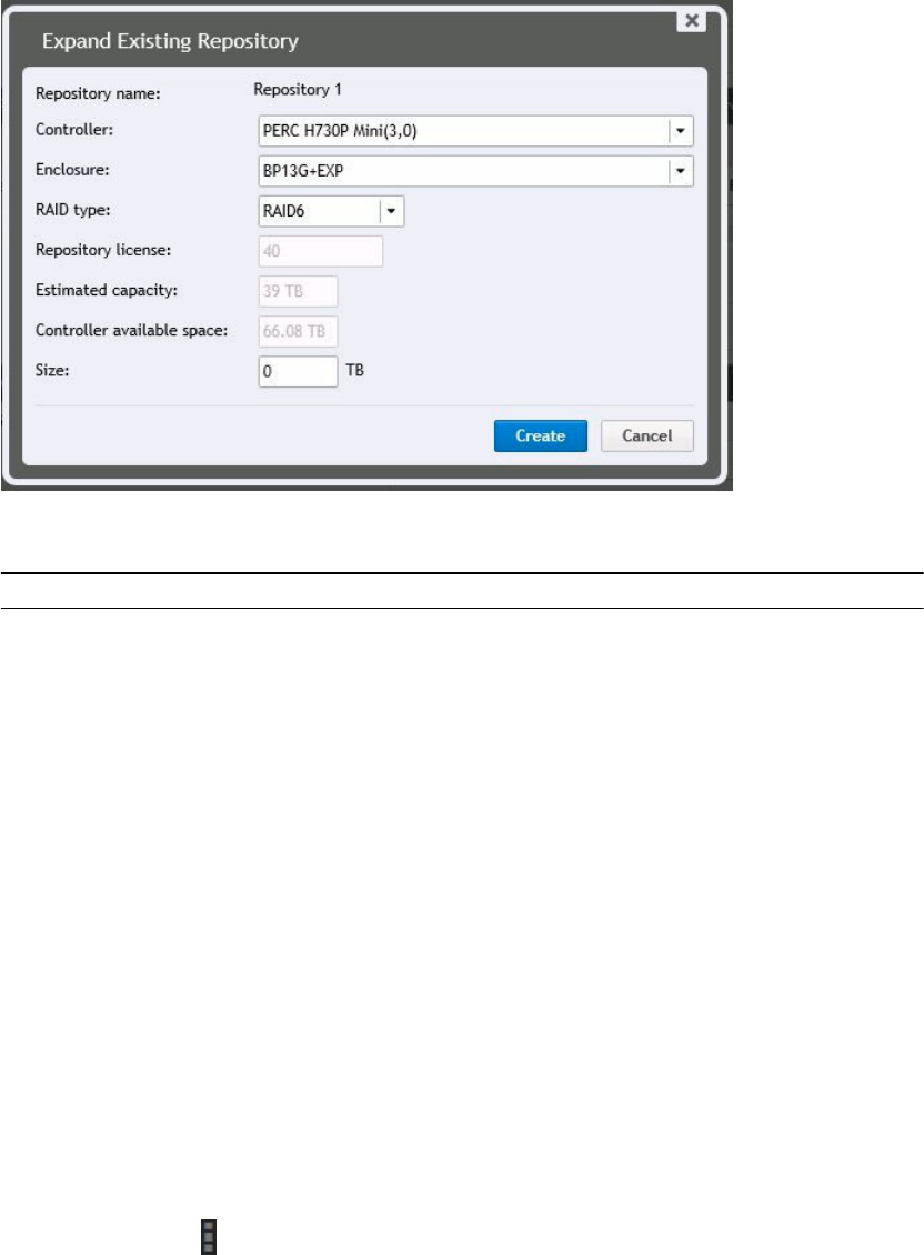
The Expand Existing Repository dialog box is displayed.
3. In the Expand Existing Repository box, specify the following information:
Table 29. Expanding existing repository
Text Box Description
Repository name The name of the repository that has to be expanded is displayed.
Controller Select the appropriate storage controller depending on whether you
are creating repository on internal storage or on direct-attached
storage enclosure.
Enclosure Select the appropriate storage enclosure.
RAID type Select the appropriate RAID configuration. You have the following
options for RAID configurations: 1, 5, or 6.
Repository license The repository license is displayed.
Estimated capacity Displays the estimated capacity available for creating a repository.
Controller available space Displays the available space on the controller.
Size Enter the size of the repository that has to be created.
4. Click Create.
A new storage location is added to the existing repository.
The repository is expanded to the specified size.
Viewing or modifying repository details
1. Navigate to the Rapid Recovery Core Console.
2. On the icon bar, click (More), and then select Repositories.
The Repositories page appears.
81
The DVM Repositories pane appears.
3. From the Repositories page menu, you can perform the following general actions:
Option Description
Add New DVM Repository Add a new DVM repository.
Open Existing DVM
Repository
Open an existing DVM repository from another Core, which changes
ownership of the repository to this Core.
For more information, see Opening an existing DVM repository.
Refresh View or refresh the list of repositories.
4. In the DVM Repositories pane, from the drop-down menu for any DVM repository, you can
perform the following additional actions:
Option Description
Add Storage
Location
Extend the existing repository by adding a storage location
NOTE: When extending a DVM repository volume, first pause protection.
Then extend the volume, and finally, resume protection. This action
prevents a rare error that can occur only when extending a volume
simultaneous with a specific transfer phase.
Check Perform a repository check
Settings View or modify repository settings. These settings include:
• Viewing the repository name
• Viewing or changing the maximum concurrent operations
• Viewing or changing a description for the repository
• Enabling or disabling deduplication
• Enabling or disabling compression for data stored in the repository
Perform
Optimization Job
Perform a repository optimization job
Delete Delete a repository
NOTE: When extending a DVM repository volume, first pause protection. Then extend the
volume, and finally, resume protection. This action prevents a rare error that can occur when
extending at a specific transfer phase.
You can perform the following general actions from the Repositories page:
• View or refresh the list of repositories
• Add a new repository
• Open an existing repository from another Core, which changes ownership to this repository
Adding a storage location to an existing DVM repository
NOTE: It’s recommended that you expand the repository through Appliance tab. For more
information, see Expanding repository
Adding a storage location to a DVM repository lets you define where you want the repository or volume
to be stored.
82

Complete the steps in the following procedure to specify the storage location for the repository or
volume.
1. Navigate to the Rapid Recovery Core Console.
2. On the icon bar, click (More), and then select Repositories.
The Repositories page appears.
The DVM Repositories pane appears.
3. In the repositories summary table, from the row representing the DVM repository for which you want
to add a storage location, click Settings and select Add Storage Location.
The Add Storage Location dialog box displays.
4. Specify how to add the file for the storage location. You can choose to add the file on the local disk
or on a CIFS share.
• Select Add file on local disk to specify a local machine and then enter the information as
described in the following table.
Table 30. Local disk settings
Text Box Description
Data Path Enter the location for storing the protected data.
For example, type X:\Repository\Data.
The same limitations to the path apply; use only alphanumeric characters,
hyphen, or period, with no spaces or special characters.
Metadata Path Enter the location for storing the protected metadata.
For example, type X:\Repository\Metadata.
When specifying the path, use only alphanumeric characters, the hyphen, and
the period (only to separate host names and domains). The letters a to z are
case-insensitive. Do not use spaces. No other symbols or punctuation
characters are permitted.
• Or, select Add file on CIFS share to specify a network share location and then enter the
information as described in the following table.
Table 31. CIFS share credentials
Text Box Description
UNC Path Enter the path for the network share location.
If this location is at the root, define a dedicated folder name (for example,
Repository).
The path must begin with \\. When specifying the path, use only alphanumeric
characters, the hyphen, and the period (only to separate host names and
domains). The letters a to z are case-insensitive. Do not use spaces. No other
symbols or punctuation characters are permitted.
User Name Specify a user name for accessing the network share location.
Password Specify a password for accessing the network share location.
5. In the Storage Configuration pane, click More Details and enter the details for the storage location as
described in the following table.
83
Table 32. Storage location details
Text Box Description
Size Set the size or capacity for the storage location.The default size is 250 GB. You can
choose from the following:
• GB
• TB
NOTE: The minimum size is 1 GB. The size that you specify cannot exceed
the size of the volume.
If the storage location is a New Technology File System (NTFS) volume using
Windows XP or Windows 7, the file size limit is 16 TB.
If the storage location is a NTFS volume using Windows 8, 8.1 or Windows
Server 2012, 2012 R2, the file size limit is 256 TB.
NOTE: For Rapid Recovery to validate the operating system, Windows
Management Instrumentation (WMI) must be installed on the intended
storage location.
Write Caching
Policy
The write caching policy controls how the Windows Cache Manager is used in the
repository and helps to tune the repository for optimal performance on different
configurations.
Set the value to one of the following:
• On
• Off
• Sync
If set to On, which is the default, Windows controls the caching. This is
appropriate for Windows 10, and for versions of Windows Server 2012 and
later.
NOTE: Setting the write caching policy to On could result in faster
performance. If you are using Windows Server 2008 SP2 or Windows
Server 2008 R2 SP2, the recommended setting is Off.
If set to Off, Rapid Recovery controls the caching.
If set to Sync, Windows controls the caching as well as the synchronous input/
output.
Bytes per
Sector
Specify the number of bytes you want each sector to include. The default value is
512.
Average Bytes
per Record
Specify the average number of bytes per record. The default value is 8192.
6. Optionally, if you want to perform the repository optimization job for the selected repository, select
Run Repository Optimization Job for [Repository name].
Dell recommends performing the Repository Optimization Job when adding storage locations to an
existing repository. This job optimizes the free space by applying deduplication to data stored in the
repository.
Based on factors such as the size of your repository, amount of data in your repository, available
network bandwidth, and existing load on the input and output of your system, performing a
84

Repository Optimization Job could take a substantial amount of time and bandwidth in your
environment.
For more information about the repository optimization job, see About the Repository Optimization
Job.
7. Click Save.
The dialog box closes and the storage location is saved. In the repositories summary table, the
storage location you created is visible if you expand the repository details.
About checking the integrity of DVM repositories
Rapid Recovery Core, users can to set disparate retention policies between source and target Cores. For
replication to work properly with different retention policies, the target Core must have the same
software version (or newer) than the source Core.
NOTE: The Cores must share the same three digits for the release number (for example, both start
with 6.0.1.xxxx, or 5.4.3.xxxx). The build number (represented by xxxx) can be different only if the
target Core is newer.
Administrators can now configure rollup on a target Core at a different rate than on the source Core.
Similarly, you can now define a custom retention policy for any replicated machine. For example, you can
roll up recovery points in the target Core at a faster rate and with less granularity than on the source
Core, saving space. Or you can roll up recovery points for any selected replicated machine at a slower
rate in the target Core, maintaining more granularity, which may be useful for compliance purposes. For
more information on using a retention policy that differs from the default in the Core, see Customizing
retention policy settings for a protected machine.
If your Core has been upgraded at any point from AppAssure 5.3.x and you used replication, you must run
this job before you can configure dissimilar retention policies between the source Core and a target
Core, or configure a custom retention policy on a replicated machine.
You will not see or be able to run this job unless you have one or more eligible repositories (created prior
to 5.4.x and not yet performed).
Running this job verifies the integrity of all data stored in the specified repository, ensuring you can
recover data from each snapshot or base image. If the integrity check discovers any issue with data in
your repository, the job ceases immediately. The event details for that job on the Core prompt you to
contact Dell Support, so you can schedule time to work with a Support representative to perform
additional procedures to identify and remediate data inconsistencies.
CAUTION: Running this job is expected to take an extended period of time. The amount of time
differs based on the amount and type of data in your repository, and on the underlying storage
system. While the job is running, no other transactions can be performed in that repository,
including transfers (snapshot and base image backups, and replication), nightly jobs, and so on.
You can perform other operations in other repositories while this job is running.
NOTE: This job checks the integrity of all of the contents within a repository. For information about
the Integrity Check job, which you can use to ensure that a repository is mountable and usable,
see Checking a repository.
85

Checking a repository
Rapid Recovery lets you perform a diagnostic check of a DVM repository volume when errors occur.
Core errors could be the result of it being improperly shut down, a hardware failure, or other
environmental, lower IP stack factors that can be exposed in Rapid Recovery functionality.
NOTE: This procedure should only be performed for diagnostic purposes. For example, run this
check in the event of hardware failure, improper shutdown of the Core, or failure when importing a
repository.
1. Navigate to the Rapid Recovery Core Console.
2. On the icon bar, click (More), and then select Repositories.
The Repositories page appears.
The DVM Repositories pane appears.
3. To check a DVM repository, in the DVM Repositories pane, in any row of the summary table
representing a DVM repository, click and then select Check.
The Check Repository dialog box appears.
4. In the Check Repository dialog box, confirm that you understand that all active tasks associated with
this repository will be canceled and that you want to proceed.
Active jobs are canceled and the Check Repository Job starts.
5. Optionally, can you track the status of the job by clicking the Running tasks drop-down menu in the
button bar, and selecting the Maintaining repository job.
About the Repository Optimization Job
When using a DVM repository, the data you capture in each snapshot is deduplicated. This deduplication
occurs incrementally, as snapshots are saved to the repository. One occurrence of each string of
information is saved to the repository. When an information string is duplicated, a reference to the
original string in the deduplication cache is used, saving storage space in the repository.
If the DVM deduplication cache is filled, only snapshot data that is already referenced in the cache is
deduplicated. As deduplication occurs, the cache continues to update with new unique values,
overwriting the oldest values in the cache. This results in less than optimal deduplication.
For more information about deduplication, see Understanding deduplication cache and storage
locations.
You can choose to increase your DVM duplication cache before it is full, which ensures continued
optimal deduplication of your data in that repository. For more information, see Configuring DVM
deduplication cache settings.
You can also increase your deduplication cache after it is full. If you want to reclaim space in the
repository after increasing your cache, you can optimize the repository. This action forces a comparison
of the data in your snapshots to the information in the deduplication cache. If any repeated strings are
found in the repository, that data is replaced with references to the data, which saves storage space in the
repository. This is sometimes referred to as off-line deduplication, since this deduplication process
occurs upon your request, instead of incrementally as snapshot data is transferred.
86

The optimization process is processor-intensive. The amount of time it takes to run this job depends on
several factors. These factors include the size of your repository; the amount of data in your repository;
available network bandwidth; and existing load on the input and output of your system. The more data in
your repository, the longer this job runs.
The following actions are superseded or canceled when the Repository Optimization Job is occurring.
• Delete Recovery Points Job
• Maintain Repository Job
• Check Repository Integrity Job
The following actions are superseded or canceled when the optimization job is occurring.
• Delete All Recovery Points Job
• Delete Recovery Points Chain Job
• Maintain Repository Job
• Delete Recovery Points Job Base
• Check Repository Integrity Job
For steps on optimizing an existing DVM repository, see Optimizing a DVM repository.
You can interrupt the repository optimization job for a limited time if required. For more information, see
Interrupting or Resuming the Repository Optimization Job.
Optimizing a DVM repository
You must have a DVM repostiory in your Core to perform this procedure.
You can perform offline deduplication of data saved to an existing DVM repository. This is accomplished
by launching the Repository Optimization Job.
NOTE: Dell recommends performing the Optimize Repository job only after increasing your
deduplication cache size. This action lets you reclaim repository space and more effectively use the
DVM deduplication cache.
Complete the steps in this procedure to optimize a DVM repository.
1. Navigate to the Rapid Recovery Core Console.
2. On the icon bar, click (More ), and then select Repositories.
The Repositories page appears.
3. In the DVM Repositories pane, from the row representing the repository you want to optimize, click
and then select Perform Optimization Job.
A warning prompt appears asking you to confirm the optimization.
4. Click to confirm the optimization.
The optimization job takes precedence over most other jobs. If necessary, you can interrupt an
optimization job in progress. For more information on interrupting or resuming this job, see
Interrupting or Resuming the Repository Optimization Job.
87
Interrupting or Resuming the Repository Optimization Job
When you initiate the Optimize Repository Job, the selected DVM repository is deduplicated. This
deduplication optimization is a processor-intensive job intended to save space in the repository. For
more information, see About the Repository Optimization Job.
Once this job has been initiated, you can interrupt the job using the following procedure. This pauses
deduplication. If you have already interrupted a optimization, you can resume the process using this
procedure.
NOTE: This procedure applies only to DVM repositories and only when the repository optimization
job has been initiated.
Complete the steps in this procedure to interrupt or resume a repository optimization job.
1. Navigate to the Rapid Recovery Core Console.
2. On the icon bar, click (More), and then select Repositories.
The Repositories page appears.
The DVM Repositories pane appears.
3. If you want to interrupt an optimization job, do the following:
a. In the repositories summary table, from the row representing the appropriate repository, click
and then select Interrupt Optimization Job.
A warning prompt appears asking you to confirm the interruption.
b. Click to confirm the optimization.
4. If you want to resume an interrupted optimization job, do the following:
a. In the repositories summary table, from the row representing the appropriate repository, click
and then select Continue Optimization Job.
A warning prompt appears asking you to confirm the interruption.
b. In the dialog box, select the option Continue job from the interrupted point, and then click Yes.
The dialog box closes, and the repository optimization job resumes from the point where it was last
interrupted.
Opening an existing DVM repository
As the primary repository technology for Rapid Recovery, the DVM repository contains snapshot data (in
the form of recovery points) from the machines protected on a specific Rapid Recovery Core. You can
open an existing repository from one Core (for example, Core A) on a second Core (Core B).
NOTE: Opening a repository from another Core changes ownership of the repository. When you
open an existing repository, the information is then accessible only to the second Core.
In the case of a DVM repository, the original Core (Core A) must not be in current use. For example, the
machine must be turned off, not accessible to the network, or the Core services must be stopped.
The repository can be on a shared network location, or on a storage device accessible to the second
Core.
88
Complete the following procedure to open an existing repository.
1. Navigate to the Rapid Recovery Core Console.
2. On the icon bar, click (More), and then select Repositories.
The Repositories page appears.
The DVM Repositories pane also appears.
3. To open an existing DVM repository, at the top of the page, click Open Existing DVM Repository.
The Open Existing DVM Repository dialog box appears.
4. In the Open Existing DVM Repository dialog box, enter the following information for the repository
you want to open, and then click Open.
Table 33. Open Existing DVM Repository options
Text Box Description
Path The path for the repository (for example, D:\work\machine for a local path, or \
\10.10.99.155\repositories by IP address, or \\servername\sharename for a network
path).
User name If the repository has a network path, enter the user name for logging in to the
network share.
Password If the repository has a network path, enter the password for logging in to the
network share.
The dialog box closes, and the selected repository is added to your current Core.
Deleting a repository
Complete the steps in this procedure to delete a repository.
1. Navigate to the Rapid Recovery Core Console.
2. On the icon bar, click (More), and then select Repositories.
The Repositories page appears.
On the Repositories page, the DVM Repositories pane appears.
3. In the repositories summary table, from the row representing the repository you want to delete, click
to expand the drop-down menu, and then select Delete.
A warning message appears to confirm deletion.
4. Click Yes to confirm the deletion of the repository.
CAUTION: When a repository is deleted, the data contained in the repository is discarded and
cannot be recovered.
Running the Check Repository Job on a DVM repository
Perform this procedure to check the integrity of an entire DVM repository. This is recommended for
replicated target cores when upgrading from AppAssure 5.3.x to release 5.4. During the execution of the
integrity check, which can be lengthy, no other actions can be performed in the repository.
If you have multiple DVM repositories for a target Core, perform this process once for each repository.
89
NOTE: If you have another DVM repository on the target Core for which the Integrity Check job has
already been completed, or if you create a new additional repository for this target Core, you can
perform operations in that secondary repository while the integrity check job is running on the DVM
repository you specified.
1. Navigate to the Rapid Recovery Core Console.
2. On the icon bar, click (More), and then select Repositories..
The Repositories page appears.
The DVM Repositories pane appears.
3. In the repositories summary table, from the row representing the repository you want to check, click
and from the drop-down menu, select Check Repository Job.
A confirmation message appears.
CAUTION: Before you confirm that you want to perform the job, you should carefully
consider the duration of time required. While the job is running, no other transactions can be
performed in that repository, including transfers (snapshot and base image backups, and
replication), nightly jobs, and so on.
4. From the Check Repository Job dialog box, to perform the integrity check, click Yes.
The dialog box closes. Any jobs that were queued or that are in progress are canceled, and the
integrity check job begins.
5. To monitor the progress of the Check Repository Job for a repository, including a determination of
whether additional steps are required after the check, from the icon bar, click (Events).
6. From the Events page, click Job Details for the job to view more information about the job
status.
• If you see an error in any child tasks for this job, note the error and provide the information to a
Dell technical support representative.
• If the Check Repository Job completes all child tasks successfully, you can then establish a
custom retention policy for this repository.
Managing security
The Core can encrypt protected machine snapshot data within the repository. Instead of encrypting the
entire repository, you can specify an encryption key during the protection of a machine in a repository
which lets the keys be reused for different protected machines. Encryption does not affect performance,
as each active encryption key creates an encryption domain, thus letting a single core support
multitenancy by hosting multiple encryption domains. In a multi-tenant environment, data is partitioned
and deduplicated within the encryption domains. Because you manage the encryption keys, loss of the
volume cannot leak the keys. Key security concepts and considerations include:
• Encryption is performed using 256 bit AES in Cipher Block Chaining (CBC) mode that is compliant
with SHA-3.
• Deduplication operates within an encryption domain to ensure privacy.
• Encryption is performed without impact on performance.
• You can add, remove, import, export, modify, and delete encryption keys that are configured on the
Core.
90

• There is no limit to the number of encryption keys you can create on the Core.
Applying or removing encryption from a protected machine
You can secure the data protected on your Core at any time by defining an encryption key and applying it
to one or more protected machines in your repository. You can apply a single encryption key to any
number of protected machines, but any protected machine can only use one encryption key at a time.
The scope of deduplication in Rapid Recovery is limited to protected machines using the same repository
and encryption key. Therefore, to maximize the value of deduplication, Dell recommends applying a
single encryption key to as many protected machines as is practical. However, there is no limit to the
number of encryption keys you can create on the Core. Thus, if legal compliance, security rules, privacy
policies, or other circumstances require it, you can add and manage any number of encryption keys. You
could then apply each key to only one protected machine, or any set of machines in your repository.
Any time you apply an encryption key to a protected machine, or dissociate an encryption key from a
protected machine, Rapid Recovery takes a new base image for that machine upon the next scheduled or
forced snapshot. The data stored in that base image (and all subsequent incremental snapshots taken
while an encryption key is applied) is protected by a 256-bit advanced encryption standard. There are no
known methods for compromising this method of encryption.
If you change the name or passphrase for an existing encryption key currently used to a protected
machine, then upon the next scheduled or forced snapshot, Rapid Recovery Core captures and reflects
the updated properties of the key. The data stored in that image (and all subsequent incremental
snapshots taken while an encryption key is applied) is protected by a 256-bit advanced encryption
standard. There are no known methods for compromising this method of encryption.
Once an encryption key is created and applied to a protected machine, there are two concepts involved
in removing that encryption. The first is to disassociate the key from the protected machine. Optionally,
once the encryption key is disassociated from all protected machines, it can be deleted from the Rapid
Recovery Core.
This section includes the following topics:
•Associating an encryption key with a protected machine
•Applying an encryption key from the Protected Machines page
•Disassociating an encryption key from a protected machine
Associating an encryption key with a protected machine
You can apply an encryption key to a protected machine using either of two methods:
•As part of protecting a machine. When using this method, you can apply encryption to one or
multiple machines simultaneously. This method lets you add a new encryption key, or apply an
existing key to the selected machine or machines.
To use encryption when first defining protection for a machine, you must select the advanced options
in the relevant Protect Machines Wizard. This selection adds an Encryption page to the wizard
workflow. From this page, select Enable encryption, and then select an existing encryption key or
specify parameters for a new key. For more information, see Protecting a machine or About
protecting multiple machines, respectively.
•By modifying the configuration settings for a machine. This method applies an encryption key to
one protected machine at a time. There are two approaches for modifying configuration settings for a
machine in the Rapid Recovery UI:
91

– Modify the configuration settings for a specific protected machine. The encryption key you want
to use for this approach must already exist on the Rapid Recovery Core, be a universal key type,
and must be in an unlocked state. Encryption is part of the General settings. For more information,
see Viewing and modifying protected machine settings.
– Click the Not Encrypted icon on the Protected Machines page. Using this approach you can
create and apply a new encryption key, or assign an existing unlocked universal key to the
specified protected machine. For more information, see Applying an encryption key from the
Protected Machines page.
Applying an encryption key from the Protected Machines page
Once an encryption key has been added to a Rapid Recovery Core, it can be used for any number of
protected machines.
If you select an encryption key during the initial protection of one or more machines, that key is
automatically applied to any machines you protect using that wizard. In such cases, this procedure is not
required.
Perform this procedure:
• If you want to apply an existing, universal, unlocked encryption key to any protected machine in your
Core.
• If you just added a new encryption key using the process described in the topic Adding an encryption
key and want to apply that key to a protected machine.
• If encryption is already applied to a protected machine in your Core, but you want to change the key
to a different universal, unlocked key available in your Core.
CAUTION: After you apply an encryption key to a protected machine, Rapid Recovery takes a new
base image for that machine upon the next scheduled or forced snapshot.
1. Navigate to the Rapid Recovery Core and click Protected Machines.
The Protected Machines page appears, listing all the machines protected by this Core. An open lock
appears for any machine that does not have an encryption key applied. A closed lock
indicates that a protected machine has encryption applied.
2. In the Protected Machines pane, click the lock icon for the protected machine you want to
configure.
The Encryption Configuration dialog box appears.
3. Do one of the following:
• If you want to apply an existing encryption key to this machine, select Encrypt data using Core-
based encryption with an existing key, and from the drop-down menu, select the appropriate
key. Click OK to confirm.
• If you want to change an existing encryption key to a different universal, unlocked key, select
Encrypt data using Core-based encryption with a new key, and from the drop-down menu,
select the appropriate key. Click OK to confirm.
• If you want to create a new encryption key and apply it to this protected machine, select Encrypt
data using Core-based encryption with a new key. Then enter the details for the key as
described in the following table.
Table 34. New encryption key details
Text Box Description
Name Enter a name for the encryption key.
92

Text Box Description
Encryption key names must contain between 1 and 64 alphanumeric
characters. Do not use prohibited characters or prohibited phrases.
Description Enter a descriptive comment for the encryption key. This information appears in
the Description field when viewing a list of encryption keys in the Rapid
Recovery Core Console. Descriptions may contain up to 254 characters.
Best practice is to avoid using prohibited characters and prohibited phrases.
Passphrase Enter a passphrase used to control access.
Best practice is to avoid using prohibited characters.
Record the passphrase in a secure location. Dell Support cannot recover a
passphrase. Once you create an encryption key and apply it to one or more
protected machines, you cannot recover data if you lose the passphrase.
Confirm
Passphrase
Re-enter the passphrase. It is used to confirm the passphrase entry.
4. Click OK.
The dialog box closes. The encryption key you specified has been applied to future backups for this
protected machine, and the lock now appears as closed.
Optionally, if you want the encryption key applied immediately, force a snapshot. For more
information, see Forcing a snapshot.
CAUTION: Rapid Recovery uses AES 256-bit encryption in the Cipher Block Chaining (CBC)
mode with 256-bit keys. While using encryption is optional, Dell recommends that you
establish an encryption key, and that you protect the passphrase you define. Store the
passphrase in a secure location as it is critical for data recovery. Without a passphrase, data
recovery is not possible.
Disassociating an encryption key from a protected machine
Once an encryption key is applied to a protected machine, all subsequent snapshot data stored in the
Rapid Recovery Core is encrypted.
You can disassociate an encryption key from a protected machine. This action does not decrypt the
existing backup data, but does result in a new base image for that machine at the time of the next
scheduled or forced snapshot.
NOTE: If you want to remove an encryption key from the Core, as described in the topic Removing
an encryption key, you must first disassociate that encryption key from all protected machines.
Perform this procedure to disassociate an encryption key from a specific protected machine.
1. Navigate to the Rapid Recovery Core and click Protected Machines.
The Protected Machines page appears, listing all the machines protected by this Core. An open lock
appears for any machine that does not have an encryption key applied. A closed lock
indicates that a protected machine has encryption applied.
2. In the Protected Machines pane, click the Encrypted icon for the protected machine you want
to configure.
93

The Encryption Configuration dialog box appears.
3. Select Encrypt data using Core-based encryption with an existing Key, and from the drop-down
menu, select (None) and then click OK.
4. If you want to remove this encryption key from the Rapid Recovery Core, first repeat this procedure
for all protected machines using this key. Then perform the procedure described in the topic
Removing an encryption key.
Managing encryption keys
To manage encryption keys for the Rapid Recovery Core, from the icon bar, click (More) and then
select Encryption Keys. The Encryption Keys page appears. For each encryption key added to your Rapid
Recovery Core (if any have been defined yet), you see the information described in the following table.
Table 35. Information about each encryption key
UI Element Description
Select Item For each encryption key, you can select the checkbox to perform actions from the list
of menu options above the table.
Name The name associated with the encryption key.
Thumbprint This parameter is a 26-character alphabetic string of randomly generated English
upper and lower case letters that helps uniquely identify each encryption key.
Type Type describes the origin point of an encryption key and its ability to be applied. An
encryption key can contain one of two possible types:
Universal. Universal type is the default condition when you create an encryption key.
A key with a type of Universal, combined with a state of Unlocked, indicates that the
key can be applied to a protected machine. You cannot manually lock a universal key
type; instead, you must first change its type as described in the procedure Changing
encryption key types.
Replication. When a protected machine in a source Core has encryption enabled, and
recovery points for that machine are replicated in a target Core, any encryption keys
used in the source appear automatically in the target Core with a type of Replication.
The default state after receiving a replicated key is locked. You can unlock an
encryption key with a type of Replication by providing the passphrase. If a key has a
type of Unlocked, you can manually lock it. For more information, see the topic
Unlocking an encryption key.
State The state indicates whether an encryption key can be used. Two possible states
include:
•Unlocked. An Unlocked state indicates that the key can be used immediately. For
example, you can encrypt snapshots for a protected machine, or perform data
recovery from a replicated recovery point on the target Core.
•Locked. A Locked state indicates that the key cannot be used until it is unlocked by
providing the passphrase. Locked is the default state for a newly imported or
replicated encryption key.
If the state of an encryption key is locked, it must be unlocked before it can be used.
If you previously unlocked a locked encryption key, and the duration to remain
unlocked has expired, the state changes from unlocked to locked. After the key locks
automatically, you must unlock the key again in order to use it. For more information,
see the topic Unlocking an encryption key.
94

UI Element Description
Description The description is an optional field that is recommended to provide useful information
about the encryption key such as its intended use or a passphrase hint.
At the top level of the Encryption Keys pane, you can add an encryption key or import a key using a file
exported from another Rapid Recovery Core. You can also delete keys selected in the summary table.
Once an encryption key exists for a Core, you can manage the existing keys by editing the name or
description properties; changing the passphrase; unlocking a locked encryption key; or removing the key
from the Rapid Recovery Core. You can also export a key to a file, which can be imported into another
Rapid Recovery Core.
When you add an encryption key from the Encryption Keys page, the key appears in the list of encryption
keys, but is not applied to a specific protected machine. For information on how to apply an encryption
key you create from the Encryption Keys pane, or to delete a key entirely from the Rapid Recovery Core,
see Applying or removing encryption from a protected machine.
From the Encryption Keys pane, you can manage security for the backup data saved to the Core for any
protected machine in your repository by doing the following:
•Adding an encryption key
•Importing an encryption key
•Unlocking an encryption key
•Editing an encryption key
•Changing an encryption key passphrase
•Exporting an encryption key
•Removing an encryption key
•Changing encryption key types
Adding an encryption key
Rapid Recovery uses AES 256-bit encryption in the Cipher Block Chaining (CBC) mode with 256-bit keys.
While using encryption is optional, Dell recommends that you establish an encryption key, and that you
protect the passphrase you define.
CAUTION: Store the passphrase in a secure location. Without a passphrase, you cannot recover
data from encrypted recovery points.
After an encryption key is defined, you can use it to safeguard your data. Encryption keys can be used by
any number of protected machines.
This step describes how to add an encryption key from the Rapid Recovery Core Console. This process
does not apply the key to any machines currently being protected on the Core. You can also add an
encryption key during the process of protecting a machine. For more information on adding encryption
as part of protecting one machine, see Protecting a machine. For more information on adding encryption
to two or more machines while initially protecting them, see About protecting multiple machines.
Complete the steps in this procedure to add an encryption key.
1. Navigate to the Rapid Recovery Core Console.
2. On the icon bar, click (More) and then select Encryption Keys.
95

The Encryption Keys page appears.
3. Click Add Encryption Key.
The Create Encryption Key dialog box appears.
4. In the Create Encryption Key dialog box, enter the details for the key as described in the following
table.
Table 36. Create encryption key details.
Text Box Description
Name Enter a name for the encryption key.
Encryption key names must contain between 1 and 64 alphanumeric characters.
Do not use prohibited characters or prohibited phrases.
Description Enter a comment for the encryption key.
This information appears in the Description field when viewing encryption keys
from the Core Console. You can enter up to 254 characters.
Best practice is to avoid using prohibited characters and prohibited phrases.
Passphrase Enter a passphrase used to control access.
Best practice is to avoid using prohibited characters.
CAUTION: Record the passphrase in a secure location. Dell Support cannot
recover a passphrase. Once you create an encryption key and apply it to one
or more protected machines, you cannot recover data if you lose the
passphrase.
Confirm
passphrase
Re-enter the passphrase. It is used to confirm the passphrase entry.
5. Click OK.
The dialog box closes and the encryption key you created is visible on the Encryption Keys page.
6. If you want to apply the encryption key to a protected machine, see Applying an encryption key from
the Protected Machines page.
Importing an encryption key
You can import an encryption key from another Rapid Recovery Core and use that key to encrypt data for
a protected machine in your Core. To import the key, you must be able to access it from the Core
machine, either locally or through your network. You must also know the passphrase for the encryption
key.
Complete the steps in this procedure to import an encryption key.
NOTE: This procedure does not apply the key to any protected machines. For more information on
applying the key, see Applying an encryption key from the Protected Machines page.
1. Navigate to the Rapid Recovery Core.
2. On the icon bar, click (More) and then select Encryption Keys.
The Encryption Keys page appears.
3. Click Import.
96

The File Upload dialog box appears.
4. In theFile Upload dialog box, navigate to the network or local directory containing the encryption
key you want to import.
For example, navigate to the Downloads folder for the logged-in user.
The key filename starts with "EncryptionKey-," followed by the key ID, and ending in the file
extension .key. For example, a sample encryption key name is EncryptionKey-
RandomAlphabeticCharacters.key.
5. Select the key you want to import, and then click Open.
6. In the Import Key dialog box, click OK.
The dialog box closes and the encryption key you imported is visible on the Encryption Keys page. If
the encryption key was used to protect a volume before it was exported, the state of the key is
Locked.
Unlocking an encryption key
Encryption keys may contain a state of unlocked or locked. An unlocked encryption key can be applied to
a protected machine to secure the backup data saved for that machine in the repository. From a Rapid
Recovery Core using an unlocked encryption key, you can also recover data from a recovery point.
When you import an encryption key into a Rapid Recovery Core, its default state is Locked. This is true
regardless of whether you explicitly imported the key, or whether the encryption key was added to the
Rapid Recovery Core either by replicating encrypted protected machines or by importing an archive of
encrypted recovery points.
For encryption keys added to the Rapid Recovery Core by replication only, when you unlock a key, you
can specify a duration of time (in hours, days, or months) for the encryption key to remain unlocked.
Each day is based on a 24-hour period, starting from the time the unlock request is saved to the Rapid
Recovery Core. For example, if the key is unlocked at 11:24 AM on Tuesday and the duration selected is 2
days, the key automatically re-locks at 11:24 AM that Thursday.
NOTE: You cannot use a locked encryption key to recover data or to apply to a protected machine.
You must first provide the passphrase, thus unlocking the key.
You can also lock an unlocked encryption key, ensuring that it cannot be applied to any protected
machine until it is unlocked. To lock an encryption key with a state of Universal, you must first change its
type to Replicated.
If an unlocked encryption key is currently being used to protect a machine in the Core, you must first
disassociate that encryption key from the protected machine before you can lock it.
Complete the steps in this procedure to unlock a locked encryption key.
1. Navigate to the Rapid Recovery Core.
2. On the icon bar, click (More) and then select Encryption Keys.
The Encryption Keys page appears. The State column indicates which encryption keys are locked.
3. Locate the encryption key you want to unlock, click its drop-down menu , and select Unlock.
The Unlock Encryption Key dialog box appears.
4. In the dialog box, in the Passphrase field, enter the passphrase to unlock this key.
97

5. To specify the length of time that the key remains unlocked, in the Duration option, do one of the
following:
• To specify that the key remains unlocked until you explicitly lock it, Rapid Recovery select Until
locked manually.
• To specify that the key remains locked for a duration which you configure in hours, days, or
months, do the following:
– Select the number field and enter a value between 1 and 999.
– Specify the duration number as hours, days, or months, respectively.
– Then click OK.
This option is available for encryption keys added by replication.
The dialog box closes and the changes for the selected encryption key are visible on the
Encryption Keys page.
• To specify that the key remains locked until a date and time that you specify, do the following:
– Select the Until option.
– In the text field or using the calendar and clock widgets, explicitly specify the data and time
you want the encryption key to lock.
– Then click OK.
This option is available for encryption keys added by replication.
The dialog box closes and the changes for the selected encryption key are visible on the
Encryption Keys page.
Locking an encryption key
When an encryption key state is locked, it cannot be applied to any protected machine until it is
unlocked. To lock an encryption key with a type of Universal, you must first change its type to Replicated.
Complete the steps in this procedure to lock an encryption key.
1. Navigate to the Rapid Recovery Core.
2. On the icon bar, click (More) and then select Encryption Keys.
The Encryption Keys page appears. The State column indicates which encryption keys are unlocked,
and shows the type for each key.
3. Locate the encryption key you want to lock. If its type is Universal, then click its drop-down menu
, and select Change the type to Replicated.
The Change Encryption Key Type dialog box appears.
4. In the dialog box, confirm that you want to change the key type to Replicated.
5. If you successfully changed the encryption key status to Replicated, then click its drop-down menu
, and select Lock..
The Lock Encryption Key dialog box appears.
6. In the dialog box, confirm that you want to lock the key.
The dialog box closes, and the state of the selected encryption key is now locked.
NOTE: This option is available for encryption keys added by replication.
98

Editing an encryption key
After an encryption key is defined, you can edit the name of the encryption key or the description of the
key. These properties are visible when you view the list of encryption keys in the Encryption Keys pane.
Complete the steps in this procedure to edit the name or description of an existing unlocked encryption
key.
CAUTION: After you edit the name or description an encryption key that is used to protect one or
more machines, Rapid Recovery takes a new base image. That base image snapshot occurs for
that machine upon the next scheduled or forced snapshot.
1. Navigate to the Rapid Recovery Core.
2. On the icon bar, click (More) and then select Encryption Keys.
The Encryption Keys page appears.
3. Locate the encryption key you want to edit, and do the following:
• If the key is locked, you must first unlock it. See Unlocking an encryption key
• If the key is unlocked, proceed as described below.
4. Click the drop-down menu for the specified encryption key, and select Edit.
The Edit Encryption Key dialog box appears.
5. In the dialog box, edit the name or the description for the encryption key, and then click OK.
The dialog box closes, and the changes for the selected encryption key are visible on the Encryption
Keys page.
Changing an encryption key passphrase
To maintain maximum security, you can change the passphrase for any existing encryption key.
Complete the steps in this procedure to change the passphrase for an encryption key.
CAUTION: After you edit the passphrase for an encryption key that is used to protect one or more
machines, Rapid Recovery Core captures an incremental snapshot for that machine upon the
next scheduled or forced snapshot.
1. Navigate to the Rapid Recovery Core.
2. On the icon bar, click (More) and then select Encryption Keys.
The Encryption Keys page appears.
3. Locate the encryption key you want to update, click its drop-down menu , and select Change
passphrase.
The Change Passphrase dialog box appears.
4. In the dialog box, in the Passphrase field, enter the new passphrase for the encryption.
5. In the Confirm passphrase field, re-enter the identical passphrase.
6. Click OK.
The dialog box closes and the passphrase is updated.
7. Optionally, if you use a hint in the Description field, edit the encryption key to update the hint. For
more information, see Editing an encryption key.
99

CAUTION: Rapid Recovery uses AES 256-bit encryption in the Cipher Block Chaining (CBC)
mode with 256-bit keys. Dell recommends that you record the passphrase in a secure
location and keep this information updated. Dell Support cannot recover a passphrase.
Without the passphrase, you cannot recover information from encrypted recovery points.
Exporting an encryption key
You can export an encryption key from any Rapid Recovery Core with the express purpose of using it in
another Core. When you perform this procedure, the key is saved to the Downloads folder for the active
Windows user account.
Complete the steps in this procedure to export an encryption key.
1. Navigate to the Rapid Recovery Core.
2. On the icon bar, click (More) and then select Encryption Keys.
The Encryption Keys page appears.
3. Locate the encryption key you want to export, click its drop-down menu , and select Export.
The Opening EncryptionKey-[name.key] dialog box appears.
4. In the dialog box, select Save File to save and store the encryption keys in a secure location, and then
click OK.
The encryption key downloads as a text file to the default location, such as the Downloads folder of
the active Windows user account.
5. Optionally, if you want to import this key into a different Core, copy the file to a location accessible
from that Core.
Removing an encryption key
When you remove an encryption key from the Encryption Keys page, the key is deleted from the Rapid
Recovery Core.
NOTE: Removing an encryption key does not decrypt the recovery points already saved using the
key. You must still retain and provide the passphrase for the key to recover data for existing
encrypted recovery points.
You cannot remove an encryption key that is already associated with any protected machine. You must
first view the encryption settings for each protected machine using the key, and disassociate the
encryption key you want to remove. For more information, see the topic Disassociating an encryption key
from a protected machine.
Complete the steps in this procedure to remove an encryption key.
1. Navigate to the Rapid Recovery Core.
2. On the icon bar, click (More) and then select Encryption Keys.
The Encryption Keys page appears.
3. Locate the encryption key you want to remove. Click its drop-down menu , and select Remove.
The Remove Encryption Key dialog box appears. You see a message confirming the action to
remove the encryption key.
4. In the dialog box, confirm that you want to remove the encryption key.
100

NOTE: Removing an encryption key does not decrypt the recovery points already saved using
the key. You must still retain and provide the key to recover data for existing encrypted recovery
points.
The dialog box closes, and the encryption key you removed no longer appears on the Encryption
Keys page.
Changing encryption key types
Encryption keys list one of two possible types on the Encryption Keys pane: Universal or Replication. The
type indicates the likely origin of the encryption key, and determines whether you can change its details
or passphrase. You can modify these attributes only if the type is Universal. If you need to modify these
attributes for a key with Replicated type, you must change its type to Universal using this procedure.
When you change the type of an encryption key to Universal, it is unlocked manually and can be used to
encrypt other protected machines.
NOTE: You must know the passphrase to change the type from Replicated to Universal.
Encryption keys also have two possible states: Locked or Unlocked. The state controls your ability to
apply an encryption key to a protected machine, or to restore data from a recovery point with encryption.
You can change the type of an encryption key manually only if the state is Unlocked.
When you first create an encryption key, its type is Universal, and its state is Unlocked. You can use such a
key immediately (for example, to encrypt backups for a protected machine). However, a Universal key
type cannot be locked manually. If you want to manually lock an encryption key with a type of Universal,
you must change the type to Replicated using this procedure.
You cannot change an encryption key type if it is already in use encrypting recovery points for one or
more protected machine.
Follow this procedure to change an encryption key type.
1. Navigate to the Rapid Recovery Core.
2. On the icon bar, click (More) and then select Encryption Keys.
The Encryption Keys page appears. Any encryption keys accessible to the Core appear in a summary
table. Each lists a type of Universal or Replicated.
3. Locate the encryption key you want to update.
4. If you want to change a Universal encryption key to Replication, do the following:
a. Click its drop-down menu , and select Change the type to Replicated.
The Change Encryption Key Type dialog box appears. You see a message confirming that you
want to change the type to Replicated.
• In the dialog box, confirm that you want to change the type to Replication.
The dialog box closes, and the encryption key type updates to Replication.
5. If you want to change a Replication encryption key to Universal, do the following:
a. Click its drop-down menu , and select Change the type to Universal
The Change Encryption Key Type dialog box appears. You see a message confirming that you
want to change the type to Universal.
• In the dialog box, in the Passphrase field, enter the passphrase and then click OK to confirm that
you want to change the type to Universal.
101
The dialog box closes, and the encryption key type updates to Universal.
Managing cloud accounts
This section describes how to define links to existing cloud storage provider accounts, and how to
manage those cloud accounts for use with Rapid Recovery. For example, you can archive Rapid Recovery
data to the cloud, or import archived data from the cloud.
About cloud accounts
Rapid Recovery lets you archive data to a variety of cloud providers, or import archived data stored in a
cloud account. Compatible clouds include Microsoft Azure, Amazon™, Rackspace, and any OpenStack-
based provider.
You can add an existing cloud account to the Rapid Recovery Core console. Once added, you can edit
the information, configure the account connection options, or remove the account from Rapid Recovery.
Adding a cloud account
Before you can move data in either direction between a cloud account and your Core, you must add
cloud provider account information to the Rapid Recovery Core Console. This information identifies the
cloud account in the Core Console while caching the connection information securely. This process then
lets Rapid Recovery Core connect to the cloud account to perform the operations you specify.
To add a cloud account, complete the steps in the following procedure.
1. On the Rapid Recovery Core Console icon bar, click the More icon and then select Cloud
Accounts.
The Cloud Accounts page appears.
2. On the Cloud Accounts page, click Add New Account.
The Add New Account dialog box opens.
3. Select a compatible cloud provider from the Cloud Type drop-down list.
4. Enter the details described in the following table based on the cloud type selected in Step 3.
Table 37. Cloud account details
Cloud
Type Text Box Description
Microsoft
Azure
Storage
Account Name
Enter the name of your Microsoft Azure storage account.
NOTE: The name must match the storage account name in
Azure precisely. It must contain lower case letters and numbers
only, and be between 3 and 24 characters in length.
Access Key Enter the access key for your account.
NOTE: You can enter the primary or secondary key. To obtain
the access key from your Azure account, check Keys under
Settings.
102

Cloud
Type Text Box Description
Use https
protocol
Select this option to use the secure https protocol instead of the
standard http protocol.
Display Name Enter a display name for this cloud account to display on the Rapid
Recovery Core Console; for example, Microsoft Azure 1.
Amazon™
S3
Access Key Enter the access key for your Amazon™ cloud account.
Secret Key Enter the secret key for this account.
Display Name Enter a display name for this cloud account to display on the Rapid
Recovery Core Console; for example, Amazon 1.
Powered
by
OpenStac
k
Region Enter the region for your cloud account.
User Name Enter the user name for you OpenStack-based cloud account.
Password or API
Key
Select whether to use a password or an API key, and then enter your
selection for this account.
Tenant ID Enter your tenant ID for this account.
Authentication
URL
Enter the authentication URL for this account.
Display Name Enter a display name for this cloud account to display in the Rapid
Recovery Core Console; for example, OpenStack 1.
Rackspac
e Cloud
Files
Region Use the drop-down list to select the region for your account.
User Name Enter the user name for your Rackspace cloud account.
Password or API
Key
Select whether to use a password or an API key, and then enter your
selection for this account.
Tenant ID Enter your tenant ID for this account.
Authentication
URL
Enter the authentication URL for this account.
Display Name Enter a display name for this cloud account to display on the Rapid
Recovery Core Console; for example, Rackspace 1.
5. Click Save.
The dialog box closes, and your account appears on the Cloud Accounts page of the Core Console.
Editing a cloud account
If you need to change the information to connect to your cloud account, for example to update the
password or edit the display name, you can do so on the Cloud Accounts page of the Rapid Recovery
Core Console. Complete the steps in the following procedure to edit a cloud account.
1. On the Rapid Recovery Core Console icon bar, click the More icon and then select Cloud
Accounts.
103

The Cloud Accounts page appears.
2. Next to the cloud account you want to edit, click the drop-down menu, and then click Edit.
The Edit Account window opens.
3. Edit the details as necessary, and then click Save.
NOTE: You cannot edit the cloud type.
Configuring cloud account settings
Cloud configuration settings let you determine how much time should pass between Rapid Recovery
attempts to connect to your cloud account before they time out. Complete the steps in the following
procedure to configure the connection settings for your cloud account.
1. On the Rapid Recovery Core Console icon bar, click the Settings.
The Settings page appears.
2. In the left menu, click Cloud Accounts.
3. In the Cloud Accounts table, click the drop-down menu next to the cloud account you want to
configure, and then complete one of the following actions:
• To change the cloud account connection settings, click Edit.
1. In the Cloud Configuration dialog box, complete any of the following actions:
– For Request Timeout, use the up and down arrows to determine the amount of time in
minutes and seconds that Rapid Recovery should spend on a single attempt to connect
to the cloud account when there is a delay. Connection attempts will cease after the
entered amount of time.
– For Write Buffer Size, enter the buffer size you want to reserve for writing archived data
to the cloud.
– For Read Buffer Size, enter the block size you want to reserve for reading archived data
from the cloud.
2. Click OK.
• To return the cloud configuration to the following default settings, click Reset.
–Request Timeout: 01:30 (minutes and seconds)
–Write Buffer Size: 8388608 (bytes)
–Read Buffer Size: 8388608 (bytes)
Removing a cloud account
If you discontinue your cloud service, or decide to stop using it for a particular Core, you may want to
remove your cloud account from the Core Console. Complete the steps in the following procedure to
remove a cloud account.
1. On the Rapid Recovery Core Console icon bar, click the More icon and then select Cloud
Accounts.
The Cloud Accounts page appears.
2. Next to the cloud account you want to edit, click the drop-down menu, and then click Remove.
3. In the Delete Account dialog box, click Yes to confirm that you want to remove the account.
4. If the cloud account is currently in use, a second dialog box prompts you to confirm that you still
want to remove it. Click Yes to confirm.
104

NOTE: Removing an account that is currently in use causes all archive jobs scheduled for this
account to fail.
Archiving
This section describes business cases for creating an archive, how to create an archive using Rapid
Recovery, and where you can store it.
Understanding archives
Retention policies enforce the periods for which backups are stored on short-term (fast and expensive)
media. Sometimes certain business and technical requirements mandate extended retention of these
backups, but use of fast storage is cost prohibitive. Therefore, this requirement creates a need for long-
term (slow and cheap) storage. Businesses often use long-term storage for archiving both compliance
and non-compliance data. The archive feature in Rapid Recovery is used to support the extended
retention for compliance and non-compliance data; and it is also used to seed replication data to a
remote replica core.
Once an archive is created, it can be used in the following ways:
• An archive can be mounted as a file system for simple file or folder recovery.
• An archive can be used as the source for a bare metal restore.
• An archive can be imported into a repository.
Creating an archive
You can use this procedure to create a one-time or scheduled archive.
If you plan on creating an archive to a cloud location, first add your cloud account to the Rapid Recovery
Core Console. For more information, see Adding a cloud account.
A one-time archive is an archive created on-demand for a specified machine. A scheduled archive is an
archive that automatically recurs on the date and time you specify in the wizard. Having the ability to
schedule a recurring archive accommodates situations where you would want frequent archives of a
machine to be saved, without the inconvenience of needing to manually create the archives each time.
1. On the button bar of the Rapid Recovery Core Console, click Archive.
The Archive Wizard opens.
2. On the Archive Type page of the wizard, select one of the following options:
• One-time archive
• Continuous archive (by schedule)
3. Click Next.
4. On the Location page, select an option from the Location type drop-down list and then enter the
information as described in the following table.
105

Table 38. Archive location type options
Option Text Box Description
Local Location Enter the location for the output. It is used to define the location path where
you want the archive to reside; for example, d:\work\archive.
Networ
k
Location Enter the location for the output. It is used to define the location path where
you want the archive to reside; for example, \\servername\sharename.
User name Enter a user name. It is used to establish logon credentials for the network
share.
Password Enter a password for the network path. It is used to establish logon
credentials for the network share.
Cloud Account Select an account from the drop-down list.
NOTE: To select a cloud account, you must first have added it in the
Core Console. For more information, see Adding a cloud account.
Container Select a container associated with your account from the drop-down menu.
Folder
name
Enter a name for the folder in which the archived data is to be saved.
5. Click Next.
6. On the Machines page of the wizard, select the protected machine or machines you want to archive.
7. Click Next.
8. Do one of the following:
• If you chose to create a one-time archive, skip to Step 15.
• If you chose to create a scheduled archive, continue to Step 9
9. On the Schedule page, select one of the following options from the Send data drop-down list:
• Daily
• Weekly
• Monthly
10. Enter the information described in the following table based on your selection from Step 9.
Table 39. Send data options
Option Text Box Description
Daily At time Select the hour of the day you want to create a daily archive.
Weekly At day of
week
Select a day of the week on which to automatically create the archive.
At time Select the hour of the day you want to create an archive.
Monthly At day of
months
Select the day of the month on which to automatically create the archive.
At time Select the hour of the day you want to create an archive.
11. Optionally, if you do not want the archive job to begin at the next scheduled time after you complete
the wizard, select Pause initial archiving.
106

NOTE: You may want to pause the scheduled archive if you need time to prepare the target
location before archiving resumes. If you do not select this option, archiving begins at the
scheduled time.
12. Click Next.
13. On the Options page for a continuous archive, select one of the recycle actions described in the
following table.
Table 40. Continuous archive recycle options
Text Box Description
Incremental Lets you add recovery points to an existing archive. It compares recovery points to
avoid duplicating data that already exists in the archive.
Replace this
Core
Overwrites any pre-existing archived data pertaining to this core but leaves the
data for other cores intact.
Erase
completely
Clears all archived data from the directory before writing the new archive.
14. Optionally, select Build recovery points chains (fix orphans), and then skip to Step 18.
15. On the Options page for a one-time archive, enter the information described in the following table.
Table 41. One-time archive options
Text Box Description
Maximum Size Large archives of data can be divided into multiple segments. Select the maximum
amount of space you want to reserve for creating the archive by doing one of the
following:
• Select Entire Target to reserve all available space in the path provided on the
destination provided in Step 4. (for example, if the location is D:\work\archive,
all of the available space on the D: drive is reserved).
• Select the blank text box, use the up and down arrows to enter an amount, and
then select a unit of measurement from the drop-down list to customize the
maximum space you want to reserve.
NOTE: Amazon™ cloud archives are automatically divided into 50 GB
segments. Microsoft Azure cloud archives are automatically divided into
200 GB segments.
Recycle action Select one of the following recycle action options:
• Do not reuse. Does not overwrite or clear any existing archived data from the
location. If the location is not empty, Rapid Recovery lets you select a different
location.
• Replace this Core. Overwrites any pre-existing archived data pertaining to this
core but leaves the data for other cores intact.
• Erase completely. Clears all archived data from the directory before writing the
new archive.
• Incremental. Lets you add recovery points to an existing archive. It compares
recovery points to avoid duplicating data that already exists in the archive.
Comment Enter any additional information that is necessary to capture for the archive. The
comment will be displayed if you import the archive later.
107

Text Box Description
Build recovery
points chains
(fix orphans)
Select this option to archive the entire recovery point chain. This option is selected
by default.
16. Click Next.
17. On the Date Range page, either manually enter the start date and end date of the recovery points to
be archived, or select the date time by clicking the calendar icon followed by the clock icon below
the calendar window.
18. Click Finish.
The wizard closes.
Archiving to a cloud
When data reaches the end of a retention period, you may want to extend that retention by creating an
archive of the aged data. When you archive data, there is always the matter of where to store it. Rapid
Recovery lets you upload your archive to a variety of cloud providers directly from the Core Console.
Compatible clouds include Microsoft Azure, Amazon™, Rackspace, and any OpenStack-based provider.
Exporting an archive to a cloud using Rapid Recovery involves the following procedures:
• Add your cloud account to the Rapid Recovery Core Console. For more information, see Adding a
cloud account.
• Archive your data and export it to your cloud account. For more information, see Creating an archive.
• Retrieve archived data by importing it from the cloud location. For more information, see Importing
an archive.
Editing a scheduled archive
Rapid Recovery lets you change the details of a scheduled archive. To edit a scheduled archive, complete
the steps in the following procedure.
1. In the Rapid Recovery Core Console, click the More drop-down menu on the icon bar, and then
select Archives.
2. On the Archives page, under Schedule Archives, click the drop-down menu next to the archive you
want to change, and then click Edit.
The Add Archive Wizard opens.
3. On the Location page of the Archive Wizard, select one of the following options from the Location
Type drop-down list:
• Local
• Network
• Cloud
4. Enter the details for the archive as described in the following table based on the location type you
selected in Step 3.
108

Table 42. Archive details
Option Text Box Description
Local Location Enter the location for the output. It is used to define the location path where
you want the archive to reside; for example, d:\work\archive.
Networ
k
Location Enter the location for the output. It is used to define the location path where
you want the archive to reside; for example, \\servername\sharename.
User name Enter a user name. It is used to establish logon credentials for the network
share.
Password Enter a password for the network path. It is used to establish logon
credentials for the network share.
Cloud Account Select an account from the drop-down list.
NOTE: To select a cloud account, you must first have added it in the
Core Console. For more information, see Adding a cloud account.
Container Select a container associated with your account from the drop-down menu.
Folder
name
Enter a name for the folder in which you want to save the archived data; for
example, Rapid-Recovery-Archive-[DATE CREATED]-[TIME CREATED].
5. Click Next.
6. On the Machines page of the wizard, select the protected machine or machines that contain the
recovery points that you want to archive. Clear the machines that you do not want to archive.
7. Click Next.
8. On the Schedule page, select one of the following options from the Send data drop-down list:
• Daily
• Weekly
• Monthly
9. Enter the information described in the following table based on your selection from Step 8.
Table 43. Send data options
Option Text Box Description
Daily At time Select the hour of the day you want to create a daily archive.
Weekly At day of
week
Select a day of the week on which to automatically create the archive.
At time Select the hour of the day you want to create a daily archive.
Monthly At day of
months
Select the day of the month on which to automatically create the archive.
At time Select the hour of the day you want to create a daily archive.
10. Optionally, to postpone archiving to resume at a later time, select Pause initial archiving.
NOTE: You may want to pause the scheduled archive if you need time to prepare the target
location before archiving resumes. If you do not select this option, archiving begins at the
scheduled time.
11. Click Next.
109

12. On the Options page, use the Recycle action drop-down list to select one of the options described
in the following table:
Table 44. Archive recycle options
Text Box Description
Increment
al
Lets you add recovery points to an existing archive. It compares recovery points to
avoid duplicating data that already exists in the archive.
Replace
this Core
Overwrites any pre-existing archived data pertaining to this core but leaves the data for
other cores intact.
Erase
completel
y
Clears all archived data from the directory before writing the new archive.
13. Optionally select Build recovery points chains (fix orphans).
14. Click Finish.
Rapid Recovery applies your changes to the archive.
Pausing or resuming a scheduled archive
If you have an archiving job scheduled to recur, you can pause or resume this action as necessary.
There may be times when you want to pause a scheduled archive job, such as if you need to change the
destination archive location. Also, if you opted to initially pause archiving when you performed the
Creating an archiveprocedure, you likely want to resume the scheduled archive later. Complete the steps
in the following procedure to pause or resume scheduled archive.
1. From the Rapid Recovery Core Console, and click the More menu on the icon bar, and then click
Archives.
2. On the Archives page, under Scheduled Archives, do one of the following:
• Select the preferred archive, and then click one of the following actions as appropriate:
– Pause
– Resume
• Next to the preferred archive, click the drop-down menu, and then click one of the following
actions as appropriate:
– Pause
– Resume
The status of the archive displays in the Schedule column.
Forcing an archive job
Using this procedure, you can force Rapid Recovery to perform the archive job on a scheduled archive at
any time.
110

To force an archive job, you must have an archive scheduled on the Core.
1. From the Rapid Recovery Core Console, in the icon bar, click the More drop-down, and then
select Archives.
2. On the Archives page, under Schedule Archives, click the drop-down menu next to the archive you
want to force, and then click Force.
Rapid Recovery archives the recovery points according to the settings you chose for that archive,
regardless of the scheduled archive time you set.
Checking an archive
Checking an archive verifies whether an archive and its contents are healthy enough to be restored.
You can scan an archive for the integrity of its structure, data segments, and index files by performing an
archive check. The archive check verifies the presence of all necessary files within the archive and that
the files are healthy. To perform an archive check, complete the steps in the following procedure.
1. From the Rapid Recovery Core Console, click the More drop-down menu in the icon bar, and
then select Archives.
2. On the Archives page, click Check.
The Check Archive dialog box appears.
3. For Location type, select one of the following options from the drop-down list:
• Local
• Network
• Cloud
4. Based on the location type you selected in Step 3, enter the details for the archive as described in the
following table.
Table 45. Archive details
Option Text Box Description
Local Location Enter the path for the archive.
Network Location Enter the path for the archive.
User Name Enter the user name. It is used to establish logon credentials for the
network share.
Password Enter the password for the network path. It is used to establish logon
credentials for the network share.
Cloud Account Select an account from the drop-down list.
NOTE: To select a cloud account, you must first have added it in the
Core Console. For more information, see Adding a cloud account.
Container Select a container associated with your account from the drop-down
menu.
111

Option Text Box Description
Folder
Name
Select the folder in which the archived data is saved; for example, Rapid
Recovery -5-Archive-[DATE CREATED]-[TIME CREATED]
5. Select or clear the checks described in the following table. All are selected by default.
NOTE: Do not clear all checks. You must select at least one option.
Option Description
Index files mapping
offsets
This option checks that all the data on the internal structure of the archive is in
the correct location.
Structure integrity This option verifies the presence of certain internal files and the folder structure
of the archive. If any files or folders are missing, the check fails.
Checksum integrity This option checks the integrity of the data segments in the archive to ensure
that the segments are healthy.
6. Click Check File.
Rapid Recovery checks the archive according to your selections.
Attaching an archive
Attaching an archive lets you see recovery points from the archive.
You must have a pre-existing archive created in Rapid Recovery Core 6.0.1 or later to complete this
procedure. For more information, see Creating an archive.
When you attach an archive, the archive name you provide appears as an archive menu in the left
navigation menu of the Core Console. Each protected machine with recovery points in the archive is
listed separately below the archive menu. You can click any machine name in the archive and browse its
recovery points. You can then take the same actions as with any other recovery points currently visible in
your Core.
Attaching the archive also caches the credentials for accessing the information. Until you delete the
attached archive definition, you can easily re-attach and detach the archive, making its recovery points
easily accessible.
Use this procedure to attach an archive.
1. On the Rapid Recovery Core Console, click the Archive drop-down menu, and then select
Attach Archive.
The Attach Archive dialog box appears.
2. In the Name text box, enter a name for this attached archive.
The value you type in this field appears in the left navigation menu as the archive menu name.
Following best practice for display names, the archive name should contain between 1 and 64
alphanumeric characters, including spaces. Do not use prohibited characters. or prohibited phrases.
3. In the Location type drop-down list, select the location type of your archive from the following
options:
• Local
• Network
112

• Cloud
4. Enter the details for the archive as described in the following table based on the location type you
selected in Step 3.
Table 46. Location type details
Option Text Box Description
Local Location Enter the path to the archive; for example, D:\Work\Archive.
Network Location Enter the path to the archive; for example, \\servername\sharename.
User name Enter user name for logging in to the network share.
Password Enter the password for logging in to the network share.
Cloud Account Select an account from the drop-down list.
NOTE: To select a cloud account, you must first have added it in
the Core Console. For more information, see Adding a cloud
account.
Container Select the container of the archive associated with your account from
the drop-down menu.
Folder name Enter the name of the folder of the archived data; for example, Rapid-
Recovery-Archive-[DATE CREATED]-[TIME CREATED].
5. Click Attach.
The archive attaches to this Core and mounts the contents as a file system.
Importing an archive
You can use this procedure to import an archive one time, or schedule an archive to import on a
recurring basis.
When you want to recover archived data, you can import the entire archive to a specified location.
CAUTION: Perform this step only after careful consideration. Importing an archive repopulates
the repository with the contents of the archive, replacing any new data in the repository since the
archive was captured.
To import an archive, complete the steps in the following procedure.
1. On the menu bar of the Rapid Recovery Core Console, click the Archive drop-down menu
and then select Import Archive.
The Import Archive Wizard opens.
2. On the Import Type page of the wizard, select one of the following options:
• One-time import
• Continuous import (by schedule)
3. Click Next.
4. On the Location page, select the location of the archive you want to import from the drop-down list,
and then enter the information as described in the following table:
113

Table 47. Imported archive location type options
Option Text Box Description
Local Location Enter the location for the output. It is used to define the location path where
you want the archive to reside; for example, d:\work\archive.
Networ
k
Location Enter the location for the output. It is used to define the location path where
you want the archive to reside; for example, \\servername\sharename.
User name Enter a user name. It is used to establish logon credentials for the network
share.
Password Enter a password for the network path. It is used to establish logon
credentials for the network share.
Cloud Account Select an account from the drop-down list.
NOTE: To select a cloud account, you must first have added it in the
Core Console. For more information, see Adding a cloud account.
Container Select a container associated with your account from the drop-down menu.
Folder
Name
Enter a name for the folder in which you want to save the archived data.
5. Click Next.
6. On the Archive Information page of the wizard, if you want to import every machine included in the
archive, select Import all machines.
7. Complete one of the following options based on your selection:
• If you selected One-time import in Step 2, you selected Import all machines in Step 6, and all the
machines are present on the Core—as protected, replicated, or recovery points only machines—
go to Step 12.
• If you selected Continuous import (by schedule) in Step 2, you selected Import all machines in
Step 6, and at least one machine is not present on the Core—as a protected, replicated, or
recovery points only machine—click Next, and then go to Step 9.
• If you did not import all machines in Step 6, click Next, and then continue to Step 8.
8. On the Machines page, select the machines that you want to import from the archive.
• If you selected One-time import in Step 2, and at least one machine is not present on the Core—
as a protected, replicated, or recovery points only machine—use the drop-down lists to select a
repository for each machine you want to import, and then go to Step 12.
• If all machines are already present on the Core—as protected, replicated, or recovery points only
machines—go to Step 12.
9. Click Next.
10. On the Repository page, complete one of the following options:
• If a repository is associated with the Core, select one of the options in the following table.
Table 48. Repository options
Option Description
Use an
existing
Repository
Select a repository currently associated with this Core from the drop-down list.
Create a
Repository
In the Server text box, enter the name of the server on which you want to save
the new repository—for example, servername or localhost—and then see
Creating a DVM repository.
114

• If no repository is associated with the Core, enter the name of the server on which you want to
save the new repository—for example, servername or localhost—and then see Creating a DVM
repository.
11. If you chose to Continuous import (by schedule) in Step 2, on the Schedule page, select the options
described in the following table.
Table 49. Schedule import options
Option Description
Daily Click the clock icon and use the up and down arrows to select at what time you want to
the archive job to begin.
If you are using a 12-hour time system, click the AM or PM button to specify the time of
day.
Weekly Select the day of the week and then the time you want the archive job to begin.
If you are using a 12-hour time system, click the AM or PM button to specify the time of
day.
Monthly Select the day of the month and the time you want the archive job to begin.
If you are using a 12-hour time system, click the AM or PM button to specify the time of
day.
Pause
initial
importing
Select this option if you do not want the import job to begin at the next scheduled time
after you complete the wizard.
NOTE: You may want to pause the scheduled import if you need time to prepare
the target location before importing resumes. If you do not select this option,
importing begins at the scheduled time.
12. Click Finish.
Events
The Rapid Recovery Core includes predefined sets of events. These events can be used to notify
administrators of critical issues on the Core or with issues with jobs pertaining to backups, virtual export,
replication and so on.
This section describes how to view events displayed on the Rapid Recovery Core Console. You can also
learn about event notification methods and configuration, including setting up email notifications. Finally,
you can configure notifications to change the amount of time event logs are retained, and reduce
repetitive event notification.
Rapid Recovery events
The Rapid Recovery Core includes predefined sets of events, which can be used to notify administrators
of critical issues on the Core or with backup jobs on protected machines.
• You define the event types that trigger alerts, as well as the methods the system uses for these
notifications (email, toast alerts, and so on), by configuring notification groups. For more information,
see Configuring notification groups.
• If you want administrators to receive notifications using email, then in addition to configuring a
notification group, you must configure an email server, and configure an email notification template.
For more information, see Configuring an email server and Configuring an email notification template,
respectively.
115

• You can reduce the number of events of the same type and scope that appear in the Events page by
using the repetition reduction feature. The repetition reduction feature is enabled by default. You can
disable this feature, or you can control the span of time for which events are combined into a single
occurrence in the event log. For more information, see About configuring repetition reduction.
• You can control how long events and job history information is retained in the Events page of the
Core console. For more information, see Configuring event retention.
Viewing events using tasks, alerts, and journal
From the Core console, you can view events for the Core, and you can view events for a specific
protected or replicated machine.
The Events page on the Core Console displays a log of all system events related to the Rapid Recovery
Core. To access and view events for the Core, click (Events).
The Events page for a specific protected or replicated machine displays a log of events related to that
specific machine. To access and view events for a selected machine, click the machine name in the
Protected Machines menu, and from the machine Summary page, click the Events menu.
The contents of the Events page (on the Core or a specified machine) is divided into three sections:
Tasks, Alerts, and Journal. These views allow you to filter details about various events, as appropriate.
You can define how you are notified of various events by configuring notification groups. For more
information, see Configuring notification groups.
Complete the steps in the procedures below to view tasks, alerts, or all a journal of all events:
•Viewing tasks
•Viewing alerts
•Viewing all events
Viewing tasks
A task is a job that the Rapid Recovery Core must perform, such as transferring data in a regularly
scheduled backup, or performing a restore from a recovery point.
As a task is running, it is listed in the Running tasks drop-down menu at the top of the Core Console.
Clicking a running task opens the Monitor Active Task dialog box.
You can also view all tasks for the Rapid Recovery Core, or all tasks associated with a specific machine.
1. To view all tasks for the Rapid Recovery Core, from the icon bar, click (Events).
If you want to view tasks for a specific protected machine, then navigate to the Summary page of the
specified machine, and then click the Events menu.
2. To view only tasks, at the top left-hand side of the page, click Tasks. This is the default view.
The list of events is filtered to display only tasks for the Core or for the machine you selected.
3. Optionally, to filter the list of tasks by keyword, start date, end date, or any combination, do the
following:
a. To filter by keyword, enter the keyword in the Search keyword text box.
For example, you can filter by key words such as "rolling up," "archive," or "transfer."
116
b. To filter by start date and time, enter the starting date and time using one of the following
options:
• In the From text box, type the date and time in format MM/DD/YYYY HH:MM AM/PM. For
example, to search from the first day of January in 2016 at 8:00 AM, enter 1/1/2016 8:00 AM.
• To select the current date and time, click the Calendar widget in the From text box and
then click the current date. The current time will automatically appear.
• Click the Calendar widget, select the date, then click the Clock widget and select the
desired time using the controls. Click away from the calendar to accept the selected changes.
c. To further refine the list of tasks that appears, you can also define an end date and time in the
same format.
The list of tasks is immediately filtered based on the criteria you selected.
4. Optionally, you can filter the tasks appearing in the list as follows:
Option Description
To see only active tasks, click the Active tasks icon.
To see only tasks that are in the queue to be performed, click the Queued tasks icon.
To see only tasks that are waiting to be performed, click the Waiting tasks icon.
To see only tasks that have been completed, click the Completed tasks icon.
To see only tasks that have failed, click the Failed tasks icon.
5. To export the list of tasks, select a format from the list and then click Export. In the resulting
dialog box, confirm the export and then click OK.
You can export using the following formats:
Table 50. Export formats
Format Description
PDF Portable Document Format (default export format)
HTML Web page format
CSV Comma-separated values
XLS Microsoft Excel® 1997 - 2003 Workbook
XLSX Excel Workbook
The file of the type you selected is downloaded to the default location on the Core server.
6. Click the Job Details icon for any task to launch a new window with task details, which include:
• Status
• Total work (size or percentage completed)
• Start date and time
• End date and time
• Rate
• Elapsed time
117

• Phase (for child tasks)
Viewing alerts
An alert is a notification related to a task or event. Alerts types include errors, warnings, or information.
You can view a journal of important alerts for the Rapid Recovery Core, or important alerts associated
with a specific machine.
1. To view alerts for the Rapid Recovery Core, from the icon bar, click (Events), and then click
Alerts.
If you want to view alerts for a specific protected machine, navigate to the Summary page of the
specified machine, click the Events menu, and then click Alerts.
The list of events is filtered to display only important alerts for the Core or for the machine you
selected.
2. Optionally, to filter the list of important alerts by start date, end date, alert message description, or
any combination, do the following:
a. To filter by start date and time, enter the starting date and time using one of the following
options:
• In the From text box, type the date and time in format MM/DD/YYYY HH:MM AM/PM. For
example, to search from the first day of January in 2016 at 8:00 AM, enter 1/1/2016 8:00 AM.
• To select the current data and time, click the Calendar widget in the From text box and
then click the current date. The current time will automatically appear.
• Click the Calendar widget, select the date, then click the Clock widget and select the
desired time using the controls. Click away from the calendar to accept the selected changes.
b. To filter by alert message description, enter the description in the Search message text box.
For example, to see alerts only related to agents, enter "agent;' to see alerts related to transfers,
enter "transfer;" and so on.
c. To further refine the list of alerts that appears, you can also define an end date and time in the
same format.
The list of alerts is immediately filtered based on the criteria you selected.
3. Optionally, if you want to remove all alerts, click Dismiss All.
Viewing all events
You can view all events for the Rapid Recovery Core, or all events associated with a specific machine.
1. To view a journal of all events for the Rapid Recovery Core, from the icon bar, click (Events),
and then click Journal.To view all events for the Rapid Recovery Core, navigate to the Rapid
Recovery Core Home page and then click (Events).
If you want to view a journal of all events for a specific protected machine, then navigate to the
Summary page of the specified machine, click the Events menu, and then click Journal.
2. Optionally, to filter the list of all events by start date, end date, alert message description, or any
combination, do the following:
a. To filter by start date and time, enter the starting date and time using one of the following
options:
118

• In the From text box, type the date and time in format MM/DD/YYYY HH:MM AM/PM. For
example, to search from the first day of January in 2016 at 8:00 AM, enter 1/1/2016 8:00 AM.
• To select the current data and time, click the Calendar widget in the From text box and
then click the current date. The current time will automatically appear.
• Click the Calendar widget, select the date, then click the Clock widget and select the
desired time using the controls. Click away from the calendar to accept the selected changes.
b. To filter by alert message description, enter the description in the Search message text box.
For example, to see alerts only related to agents, enter "agent;' to see alerts related to transfers,
enter "transfer;" and so on.
c. To further refine the list of events that appears, you can also define an end date and time in the
same format.
The list of events is immediately filtered based on the criteria you selected.
Understanding email notifications
You can set up Rapid Recovery Core to notify you of specific events by sending an email message to an
email address that you specify. The events which trigger alerts are defined in the notification group, as are
the other notification methods.
NOTE: Notification groups must be established regardless of whether you use email as a notification
method. For more information, see Configuring notification groups.
If you choose email as one of the notification options, you must also configure an email SMTP server. The
Rapid Recovery Core uses the server you define to send alerts based on the parameters in the notification
group.
Additionally, you must also define an email notification template. The Core uses this template to define
the email subject line for each alert, and the content in the email message body. The template has default
settings; you can use the default as-is, or you can test and make modifications to serve your needs.
This section includes the following topics:
•Configuring an email server
•Configuring an email notification template
Configuring an email server
Complete the steps in this procedure to configure an email server.
NOTE: You must also configure notification group settings, including enabling the Notify by email
option, before email alert messages are sent by the system. For more information on specifying
events to receive email alerts, see Configuring notification groups.
1. Navigate to the Rapid Recovery Core Console.
2. On the icon bar, click (Settings), and then do one of the following:
• From the list of Core settings on the left side of the Settings page, click SMTP Server.
• Scroll down on the right side of the Settings page until you can see the SMTP Server heading.
The SMTP Server core settings appear.
3. Click on the setting you want to change.
119
The setting you selected becomes editable.
4. Enter the configuration information as described in the following table.
Option Description
SMTP Server Enter the name of the email server to be used by the email notification template. The
naming convention includes the host name, domain, and suffix; for example,
smtp.gmail.com.
From Enter a return email address. It is used to specify the return email address for the
email notification template; for example, noreply@localhost.com.
User name Enter a user name for the email server.
Password Enter the password associated with the user name required to access the email
server.
Port Enter a port number. It is used to identify the port for the email server; for example,
the port 587 for Gmail.
The default is 25.
Timeout
(seconds)
Enter an integer value to specify how long to try to connect to the email server. It is
used to establish the time in seconds before a timeout occurs.
The default is 60 seconds.
TLS Select this option if the mail server uses a secure connection such as Transport Layer
Security (TLS) or Secure Sockets Layer (SSL).
5. For each setting, when satisfied with your changes, click to save the change and exit edit mode,
or click to exit edit mode without saving.
CAUTION: If you do not confirm each change, your settings will not change.
6. Click Send Test Email and then do the following:
a. In the Send Test Email dialog box, enter a destination email address for the test message and
then click Send.
b. If the test message fails, exit the error dialog box and the Send Test Email dialog box, and revise
your email server configuration settings. Then send the test message again.
c. Once the test message is successful, click OK to confirm the successful operation.
d. Check the email account to which you sent the test email message.
Configuring an email notification template
When you enable notifications of Rapid Recovery events by email, a default template is created for you by
default. The SMTP email server defined for the Core uses this template to send notifications regarding
Rapid Recovery events by email.
This topic describes the process of configuring the default email notification template or customizing the
content. Using the Restore Default option, you can restore changes to the default notification template at
any time.
CAUTION: Modify the template at your own risk. You are responsible for testing any
modifications to the template. Only the default template is supported.
Complete the steps in this procedure to configure an email notification template.
120

NOTE: You must also configure an email server and notification group settings, including enabling
the Notify by email option, before email alert messages are sent. For more information about
configuring an email server for sending alerts, see Configuring an email server. For more
information on specifying events to receive email alerts, see Configuring notification groups.
1. Navigate to the Rapid Recovery Core Console.
2. On the icon bar, click (More), and then select Notifications.
The Notifications page appears.
3. In the Email Settings pane, click Change.
The Edit Email Notification Configuration dialog box appears.
4. Select Enable Email Notifications.
The email template is enabled and is visible. The values of the default email template are described in
the following step.
5. Review the contents in the Edit Email Notification Configuration dialog box and determine if the
default content suits your needs.
Option Description
Enable email
notifications
This setting enables or disables the email notification template.
• To enable email notification, select this option.
• To disable email notification, clear this option.
Email Subject The contents of this text field control the subject line for email messages sent as
notifications of system events. The default email subject line is as follows:
<hostName> <level>: <name> for <agentName>
Email The contents of this text area control the body for email messages sent as
notifications of system events. The default email body message is as follows:
<shortCompanyName> <coreProductName> on <hostName> has reported
the <level> event "<name>"
Date/Time: <localTimestamp>
<message>
<if(details.errorDetails)>
<details.ErrorDetails.Message>
<details.ErrorDetails.Details>
<endif>
---
About this event: <description>
<coreAdminUrl>
Send Test Email Clicking this button sends a test email message to the email address you specify in
the resulting Send Test Email dialog box.
Restore
Defaults
Clicking this button removes any customized changes from the email template, and
restores the Email Subject and Email fields with the default contents described in
this table.
121

Option Description
OK Clicking this button confirms and saves the settings in the Edit Email Notification
Configuration dialog box.
Cancel Clicking this button cancels any changes in the Edit Email Notification Configuration
dialog box.
6. If you want to customize the email template, make changes to the text or variables described in the
preceding step. The variables used in the default are described in the following table.
Option Description
hostName The host name of the Core
details The details object of the specific event.
agentName The name of the protected machine associated with this event, if the event
has a scope of a single protected machine.
repositoryName The name of the repository associated with this event, if the event has
repository scope.
jobSummary The summary of the job associated with this event, if the event has job
scope.
remoteSlaveCoreName The name of the remote target core associated with this event, if the event
has target core scope.
remoteMasterCoreName The name of the remote source core associated with this event, if the
event has source core scope.
productName The name of the product, 'Rapid Recovery Core.' This product name can
be changed for branding using white labeling.
companyName The name of the company selling the product.
7. In the Email Subject text box, enter a subject for the email template.
The Email Subject is used to define the subject of the email notification template, for example,
<hostname> - <level> <name>.
8. In the Email text box, enter the information for the body of the template which describes the event,
when it occurred, and the severity.
9. Click Send Test Email , and then do the following:
a. In the Send Test Email dialog box, enter a destination email address for the test message and then
click Send.
b. If the test message fails, exit the error dialog box and the Send Test Email dialog box, click OK to
save the current email template settings. Then modify your email server settings as described in
the procedure Configuring an email server. Ensure that you reenter the password for that email
account. Save those settings and then return to this procedure.
c. Once the test message is successful, click OK to confirm the successful operation.
d. Check the email account to which you sent the test email message.
Once you are satisfied with the results of your tests, return to the Edit Email Notification Configuration
dialog box, and click OK to close the dialog box and save your settings.
Notification groups, SMTP settings and notification templates for system
events
Notification groups let you define sets of specific events for which users are alerted, and the manner in
which that notification takes place. To configure or edit notification groups, see Configuring notification
groups.
You must also configure Simple Mail Transfer Protocol (SMTP) server settings if you want to send alerts as
email messages. For more information on setting email server configuration settings, see Configuring an
email server.
122

When sending notification of events, the system uses an email notification. You can customize this
template. For more information on configuring or customizing the email notification template, see
Configuring an email notification template.
Configuring notification groups
NOTE: You must also configure Simple Mail Transfer Protocol (SMTP) server settings if you want to
send alerts as email messages, as described in this procedure. For more information on setting
email server configuration settings, see Configuring an email server.
Notification groups let you define sets of specific events for which users are alerted, and the manner in
which that notification takes place. You can configure alerts to be sent by the following methods:
• By email
• In the Windows event log
• Using syslogd
• Using toast alerts
• Using alerts
• Using SNMP trap
You can configure more than one notification group with different notification parameters.
Notification groups can be set at the Core level, or for each specific protected machine.
Complete the steps in this procedure to configure notification groups for alerts.
1. Do one of the following:
• To set notifications at the Core level, from the icon bar, click (More), and then select
Notifications.
The Notifications page appears.
• To set notifications for a specific protected machine, do the following:
1. From the Protected Machines menu, click the machine for which you want to specify
notifications.
The Custom Notification Groups page appears.
2. In the Summary page of the protected machine, from the More drop-down menu, select
Notifications.
The Custom Notification Groups page appears.
2. Click Add Group
The Add Notification Group dialog box appears.
Notification groups let you define sets of specific events for which users are alerted, and the manner
in which that notification takes place. You can configure alerts to be sent by the following methods:
The Add Notification Group dialog box contains a general description area and two tabs:
• Enable Alerts
• Notification Options
123
3. In the general description area, enter the basic information for the notification group, as described in
the following table.
Option Description
Name Enter a name for the event notification group. This information is required.
CAUTION: The value you enter for the notification group name cannot be
changed later.
Description Enter a description that clarifies the purpose for the event notification group. This
information is optional.
4. On the Enable Alerts tab, define the set of system events that you want to log, create reports for, and
for which you want to be alerted, as follows:
Option Description
All Alerts To create alerts for all events, select All Alerts.
Errors To create alerts for errors, from the Select Types menu, click Error. This is
represented by a red X.
Warning To create alerts for errors, from the Select Types menu, click Warning. This is
represented by a yellow exclamation point icon.
Info To create alerts for informational messages, from the Select Types menu, click Info.
This is represented by a blue i.
Restore
Default
To restore alert types to the default, from the Select Types menu, click Restore
Default. This is represented by a dark blue left-facing arrow.
5. To create alerts for a specific event type (error, warning, or informational message), do the following:
a. If the All Alerts option does not display alert groups, click the right angle bracket > symbol
preceding the All Alerts label. The symbol changes to a downward-facing arrow, and the view
expands to show groups.
b. Then click the right angle bracket > symbol next to any specific alert group to display related
events in the group.
The event group categories include:
• Archive
• Auto Report
• Attachability
• Auto Update
• Back Up Repository
• Boot CD
• Clouds
• Clusters
• Core Service
• Database Retention
• Dedupe Cache
• DVM Repository
• Exchange
• Export
• Jobs
• Licensing
• Local Mount
124

• Log Truncation
• Metadata
• Nightly Jobs
• Notification
• Persist Core State
• PowerShell Scripting
• Protection
• Push Install
• Recovery Point Check
• Remote Mount
• Repository Common
• Replication
• Restore
• Rollup
• Scheduled Archives
• Security
• Server Logs
• vSphere
• To define alerts for all events in every group, select the checkbox for All Alerts.
• To define alerts for all events within any alert group, select the checkbox next to that group.
• To select only some alert types within an alert group, expand the group and then select only
those specific events for which you want to log, report, and set alerts.
6. Click the Notification Options tab.
7. On the Notification Options tab, specify how to handle the notification process.
Option Description
Notify by email Designate the recipients of the email notification. You can choose to specify
separate multiple email addresses as well as blind and carbon copies.
You can choose:
• To:
• CC:
• BCC:
Notify by
Windows Event
Log
Select this option if you want alerts to be reported through the Windows Event
Log.
Notify by syslogd Select this option if you want alerts to be reported through syslogd. Specify the
details for the syslogd in the following text boxes:
• Host:
• Port:
Notify by Toast
alerts
Select this option if you want the alert to appear as a pop-up in the lower-right
corner of your screen.
Notify by Alerts Select this option if you want alerts to appear as pop-up windows located at the
bottom right side of the Core Console.
Notify by SNMP
trap
The Rapid Recovery Core serves as an SNMP agent, sending traps (notifications
about specific events) to an SNMP manager. The result is the reporting of Core
information such as alerts, repository status, and protected machines. Select this
125

Option Description
option if you want to notify Core events by SNMP trap. You must also specify a
trap number. For example, the default trap number used by the Rapid Recovery
Core is 162.
8. Click OK.
You will see a message indicating that the notification group name you defined cannot be changed
after creating the group. Other properties within the notification group can be changed at any time.
• If you are satisfied with the group name, confirm this message and save your work.
• If you want to change the group name, click No to return to the Create Notification Group
window, update the group name and any other notification group settings, and save your work.
The notification group appears in the summary table. You can create different notification groups
using any set of parameters.
About configuring repetition reduction
The ability for administrators to receive alerts upon certain events is critical. Nonetheless, in certain
circumstances, receiving repeated notification of events that you are aware of can also be frustrating or
inconvenient. Even if an alert is generated due to an environmental failure that you wish to know about
immediately, it is possible for the same error condition to generate hundreds or thousands of events in
the event log. To reduce repetition in the event log, and reduce the inconvenience of receiving repeated
e-mail notifications for the same event in the Core Console, Rapid Recovery includes a repetition
reduction setting, which is enabled by default and set at 5 minutes. This setting can be set as low as 1
minute and as high as 60 minutes. It can also be disabled entirely.
When repetition reduction is disabled, then every time an event of the same type and scope occurs, it is
logged in the database. Regardless of how much time passed since that event previously occurred, each
new occurrence is shown in the Alerts portion of the Events tab.
When repetition reduction is enabled (for example, with the default time of 5 minutes), then the first time
that specific event occurs, it is logged in the events database and shown in the alerts log. If subsequently
an event of the same type and scope is again logged within the threshold of time established, then the
count for the event in the database increases by 1 for each repeat occurrence within that threshold. The
log shows in the Alerts portion of the Events page. However, it displays the event only once, with the date
and time of the most recent occurrence. The events log is not updated with the same event until the
threshold of time from the first occurrence expires. For example, if set for 5 minutes and the event occurs
again 6 minutes later, it appears in the log and you receive another email message.
Configuring repetition reduction
Complete the steps in this procedure to configure repetition reduction for events.
1. Navigate to the Rapid Recovery Core Console. From the icon bar, click (More), and then select
Notifications.
The Notifications page appears.
2. In the Repetition Reduction pane, view the existing settings.
3. To enable, disable, or change the stored events threshold time, click Change.
The Edit Repetition Reduction dialog box appears
126

4. Do one of the following:
• To disable repetition reduction, clear the Enable Repetition Reduction option.
• To enable repetition reduction, select the Enable Repetition Reduction option.
• To change the time threshold (in minutes) for which repeated identical events are ignored, in the
__ minute(s) text box, enter a number between 1 and 60.
NOTE: The Enable Repetition Reduction option must be selected in order to change this value.
5. Click OK to save your settings and close the dialog box.
Configuring event retention
Events and jobs tracked on the Core are saved for a specified amount of time. The default setting is 30
days. This number can be set between 0 days and 3652 days (approximately 10 years).
Complete the steps in this procedure to configure retention for events.
1. Navigate to the Rapid Recovery Core Console.
2. On the icon bar, click (Settings), and then do one of the following:
• From the list of Core settings on the left side of the Settings page, click Database Connection.
• Scroll down on the right side of the Settings page until you can see the Database Connection
heading.
The Database Connection settings appear.
3. To change the amount of days for which event information is saved to the database, click on the
Retention Period (days) text field, enter a value between 0 and 3652, and then click to save the
change.
The events retention period is adjusted as specified.
Rapid Appliance Self Recovery
Rapid Appliance Self Recovery (RASR) is a bare metal restore process that quickly restores your Appliance
to an operating state.
RASR offers two recovery options:
• Restore factory settings
• Recover your appliance to a state just before failure (OS, configurations, and settings are recovered)
Creating the RASR USB key
To create a RASR USB key:
1. Navigate to the Appliance tab.
2. Using the left pane navigation, select Appliance → Backup.
Create RASR USB Drive window is displayed.
NOTE: Insert a 16 GB or larger USB key before attempting to create the RASR key.
3. After inserting a 16 GB or larger USB key, click on Create RASR USB Drive now.
A Prerequisite Check message is displayed.
127

After the prerequisites are checked, Create the RASR USB Drive window displays the minimum size
required to create the USB drive and List of Possible target paths.
4. Select the target and click Create.
A warning dialog box is displayed.
5. Click Yes.
The RASR USB Drive key is created.
6. NOTE: Make sure to use the Windows Eject Drive function to prepare the USB key for removal.
Otherwise, the content in the USB key may be damaged and the USB key doesn’t work as
expected.
Remove the RASR USB key created for each DL Appliance, label, and store for future use.
Executing RASR
NOTE: Dell recommends you to create a RASR USB key after you have set up the appliance. To
create RASR USB key, see Creating the RASR USB Key section.
NOTE: Ensure that you have the latest RUU available and reachable on your appliance.
.
NOTE: To perform system recovery using RASR, see Recovering a Dell™ DL Backup and Recovery
Appliance using Rapid Appliance Self Recovery (RASR) document at Dell.com/support/home.
To perform a factory reset:
1. Insert the RASR USB key created.
2. Restart the appliance and select Boot Manager (F11).
3. In the Boot Manager Main Menu, select One-shot BIOS Boot Menu.
4. In the Boot Manager Boot Menu, select the attached USB drive.
5. Select your keyboard layout.
6. Click Troubleshoot → Rapid Appliance Self Recovery.
7. Select the target operating system (OS).
RASR is launched and welcome screen is displayed.
8. Click Next.
The Prerequisites check screen is displayed.
NOTE: Ensure all the hardware and other prerequisites are checked before performing the
RASR.
9. Click Next.
The Recovery Mode Selection screen is displayed with three options:
•System Recovery
•Windows Recovery Wizard
•Factory Reset
10. Select the Factory Reset option.
This option will recover the operating system disk from the factory image.
11. Click Next.
The following warning message is displayed in a dialog box: This operation will recover the
operating system. All OS disk data will be overwritten.
12. Click Yes.
128

The operating system disk starts restoring back to factory reset.
13. The RASR Completed page is displayed on completion of the recovery process. Click Finish.
14. Boot the system after restore.
15. NOTE: Continue further only if you see the AppAssure Appliance Configuration Wizard,
otherwise go to Step 17.
Wait for AppAssure Appliance Configuration Wizard to load, you need to close it. Close the wizard
using the Windows Task Manager.
16. Run launchRUU.exe file in the RUU package. Follow the instructions and select the option to
continue with RUU installation and complete the RUU installation.
17. The DL Appliance Configuration Wizard launches and will guide you through the rest of the restore
process.
Your appliance operates normally now.
The Local Mount Utility
This section describes how to download, install, and use the Windows-based Rapid Recovery Local
Mount Utility (LMU) to mount recovery points and explore the contents from a file level using a machine
that does not host the Rapid Recovery Core.
About the Local Mount Utility
The LMU is a downloadable Windows-based application that lets you mount a Rapid Recovery recovery
point in any of the three available modes on any Windows machine. The light-weight utility can be
installed on 32-bit as well as 64-bit Windows operating systems and includes the rapidrecovery-vdisk
(formerly aavdisk) and aavstor drivers, but it does not run as a service. When you install the utility, by
default, it is installed in the directory C:\Program Files\AppRecovery\Local Mount Utility and a shortcut
appears on the machine’s desktop.
While the utility was designed for remote access to a Rapid Recovery Core machine, you can also install
the LMU on the same machine as a Rapid Recovery Core. When it runs on a Core, the application
recognizes and displays all mounts from that Core, including mounts performed through the Rapid
Recovery Core Console. Likewise, mounts performed on the LMU also appear in the Core Console.
When the LMU is installed on the same machine as Mailbox Restore, the LMU automatically launches
Mailbox Restore when you use it to open an Exchange database. Mailbox Restore is the Dell Rapid
Recovery application used to restore Microsoft Exchange data stores and items. You can install it upon
installation of the LMU or the Rapid Recovery Core. For more information about Mailbox Restore, see the
Dell Data Protection | Rapid Recovery Mailbox Restore for Microsoft Exchange User Guide.
NOTE: Linux machines use a command-line utility, local_mount, to query the Core for protected
machines and their corresponding recovery points. Similarly, that tool lets users remotely mount a
recovery point volume; lets users explore the volume contents at the file levels; and lets users
restore a individual files or an entire volume from the recovery point, including BMR of the system
volume. For more information, see Mounting a recovery point volume on a Linux machine,
Restoring volumes for a Linux machine using the command line, and Performing a bare metal
restore for Linux machines, respectively..
129
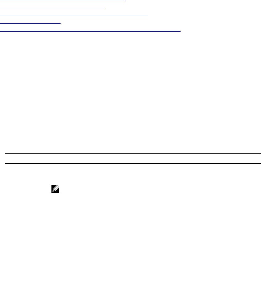
Working with Rapid Recovery Core machines in the Local Mount Utility
The Local Mount Utility (LMU) lets you work with an unlimited number of Core machines locally or
remotely. If you install the LMU on an Rapid Recovery Core machine, that machine automatically appears
in the LMU as the localhost. All additional remote Cores appear as their machine names or IP addresses,
depending on the information you entered when you added them. With the LMU, you can add, edit, and
remove Core machines. For more information, see the following procedures:
Related links
Adding a Core machine to the Local Mount Utility
Changing the Local Mount Utility options
Editing Core connection settings in the Local Mount Utility
Reconnecting to a Core
Removing a Rapid Recovery Core machine from the Local Mount Utility
Adding a Core machine to the Local Mount Utility
To mount a recovery point, you must add a Core machine to the LMU. There is no limit as to how many
Cores you can add.
Complete the following procedure to set up the LMU by adding a Core.
1. From the machine on which the LMU is installed, launch the LMU by double-clicking the desktop
icon.
2. Do one of the following:
• From the Local Mount Utility menu in the upper left-hand corner, click Add Core.
• Right-click the blank space in the left panel, and then click Add Core.
The Add Core dialog box appears.
3. In the Add Core dialog box, enter the requested credentials described in the following table.
Table 51. Rapid Recovery Core credentials
Option Description
Host name The name or IP address of the Core from which you want to mount recovery
points.
NOTE: If installing the LMU on a Rapid Recovery Core machine, the LMU
automatically adds the localhost machine.
Port The port number used to communicate with the Core.
The default port number is 8006.
Use my
Windows user
credentials
Select this option if the credentials you use to access the Core are the same as
your Windows credentials.
Use specific
credentials
Select this option if the credentials you use to access the Core are different from
your Windows credentials.
User name The user name used to access the Core machine.
130

Option Description
NOTE: This option is only available if you chose to use specific credentials.
Password The password used to access the Core machine.
NOTE: This option is only available if you chose to use specific credentials.
4. Click Connect.
5. If adding multiple Cores, repeat all steps as necessary.
Changing the Local Mount Utility options
Complete the following procedure to change the options for all Rapid Recovery Cores connected to the
LMU.
1. From the Local Mount Utility user interface, click Options.
2. In the Options dialog box, you can change the setting described in the following table.
Table 52. Core settings
Option Description
Default mount
point repository
Use the Browse button or enter a path to the location you want to use for
mounting recovery points.
Use my Windows
user account
credentials
Select this option to always use your Windows credentials by default when
logging in to a Core.
Use specific
credentials
Select this option to use the following credentials for each connected Core:
•User name: Enter the user name to use for all Cores.
•Password: Enter the password to use for all Cores.
Core connection
timeout (sec)
Enter the amount of time the LMU should continue trying to connect to a Core
before the connection times out (in minutes : seconds : milliseconds).
Language Select the language in which you want the LMU to appear. You can choose
from the following options:
• English
• French
• German
• Portuguese
• Spanish
• Simplified Chinese
• Japanese
• Korean
Editing Core connection settings in the Local Mount Utility
To edit the settings you established when you added a Core to the LMU, complete the following
procedure.
131

NOTE: This procedure does not apply to the localhost Core. It only applies to remote Core
machines.
1. From the Local Mount Utility user interface, right-click on the Core for which you want to edit
settings, and then click Edit Core.
2. In the Edit Core dialog box, you can change the settings described in the following table.
Table 53. Core settings
Option Description
Host name The name of the Core from which you want to mount recovery points.
NOTE: If installing the LMU on a Rapid Recovery Core machine, the LMU
automatically adds the localhost machine.
Port The port number used to communicate with the Core.
The default port number is 8006.
Use my
Windows user
credentials
Select this option if the credentials you use to access the Core are the same as
your Windows credentials.
Use specific
credentials
Select this option if the credentials you use to access the Core are different from
your Windows credentials.
User name The user name used to access the Core machine.
NOTE: This option is only available if you chose to use specific credentials.
Password The password used to access the Core machine.
NOTE: This option is only available if you chose to use specific credentials.
3. After you make your changes, click OK.
Reconnecting to a Core
If you lose the connection to an Rapid Recovery Core machine, you can refresh the connection with the
following step.
From the Local Mount Utility user interface, do one of the following:
• If the Core is offline, double-click the Core whose connection you want to reestablish.
The LMU attempts to reestablish a connection to the Core.
• If the Core is online, right-click the Core and then click Reconnect to Core.
The LMU refreshes the connection.
Removing a Rapid Recovery Core machine from the Local Mount Utility
Complete the following procedure to remove a Core from the LMU.
132

NOTE: This option is not available for a Rapid Recovery Core located on and labeled as the
localhost.
1. From the Local Mount Utility user interface, right-click the Core you want to remove, and then click
Remove Core.
2. To confirm the command, click Yes in the dialog box.
The LMU removes the Core and its protected machines from the navigation tree.
Working with protected machines in the Local Mount Utility
With the Local Mount Utility (LMU), you can mount and browse recovery points from protected machines
without having to be logged in to the Rapid Recovery Core Console associated with that machine. For
more information, see the following procedures:
•Mounting a recovery point using the Local Mount Utility
•Exploring a mounted recovery point using the Local Mount Utility
•Refreshing recovery points
•Dismounting individual recovery points using the Local Mount Utility
•Dismounting all recovery points from a single Rapid Recovery Core or protected machine
•Dismounting all mounted recovery points using the Local Mount Utility
Mounting a recovery point using the Local Mount Utility
With the LMU, you can mount any recovery point associated with a connected Core machine, including
protected machines, replicated machines, and recovery points only machines.
Before mounting a recovery point, the local mount utility (LMU) must connect to the Core on which the
recovery point is stored. As described in the procedure Adding a Core machine to the Local Mount Utility,
the number of Cores that can be added to the LMU is unlimited; however, the application can connect to
only one Core at a time. For example, if you mount a recovery point of a machine protected by one Core
and then mount a recovery point of another machine protected by a different Core, the LMU
automatically disconnects from the first Core to establish a connection with the second Core.
1. From the Local Mount Utility user interface, expand the Core in the navigation tree to reveal the
protected machines.
2. From the navigation tree, select the machine from which you want to mount a recovery point.
The recovery points appear in the main frame.
3. Optionally, expand the recovery point you want to mount to reveal individual disk volumes or
databases.
4. Right-click the recovery point you want to mount, and then select one of the following options:
Option Description
Mount This option lets you mount the recovery point as read-only.
Mount writable This option lets you make changes to the mounted recovery point.
Mount read-only with
previous writes This option mounts the recovery point as read-only and includes any
changes that were previously made.
Advanced mount... This option opens the Advanced Mounts dialog box.
5. If you selected Advanced Mount, complete the options described in the following table.
133

Table 54. Advanced Mount options
Option Description
Mount point
path
Click Browse to select a path for the recovery points other than the default mount
point path, or manually enter the preferred path.
Mount type Select one of the following options:
• Mount read-only
• Mount writable
• Mount read-only with previous writes
For descriptions of each option, see Step 4.
• Click Mount.
The LMU automatically opens the folder containing the mounted recovery point.
NOTE: If you select a recovery point that is already mounted, the Mounting dialog asks
whether to dismount the recovery point.
Exploring a mounted recovery point using the Local Mount Utility
Exploring a recovery point opens the backed up data in a Windows Explorer window, and lets you search
the volumes and folders for the item or items you want to recover.
You can then recover items by copying them to your preferred location using a file manager such as
Windows Explorer (or programmatically using Windows APIs). Complete the following procedure to
explore a currently mounted recovery point.
NOTE: This procedure is not necessary if you are exploring a recovery point immediately after
mounting it, as the folder containing the recovery point automatically opens upon completion of
the mounting procedure.
1. From the Local Mount Utility user interface, click Active mounts.
The Active Mounts window opens and displays all mounted recovery points.
2. Expand the navigation tree to reveal the recovery points mounted for each machine and their
volumes.
3. Click Explore next to the volume you want to explore.
Refreshing recovery points
The LMU does not receive real-time updates from the Core and protected machines. To refresh a
protected machine and see its latest recovery points, complete the following procedure.
From the Local Mount Utility user interface, right click the protected machine you want to refresh,
and then click Refresh recovery points.
Dismounting individual recovery points using the Local Mount Utility
Complete the following procedure to dismount a recovery point on a remote Core using the LMU.
1. From the Local Mount Utility user interface, click Active mounts.
The Active Mounts window opens and displays all mounted recovery points.
2. In the Active Mounts window, optionally, you can click the plus or minus icons to expand or contract
the view of volumes in each mounted recovery point.
134

3. In the Active Mounts window, Next to each recovery point or volume you want to dismount, click
Dismount.
A progress windows shows when the selected recovery points have dismounted.
4. Click the x in the top right of the Active Mounts window to close the window and return to the LMU.
Dismounting all recovery points from a single Rapid Recovery Core or protected machine
Complete the following procedure to dismount only the recovery points that are mounted from a single
Core or a protected machine.
1. From the Local Mount Utility user interface, do one of the following:
• Right-click the Core for which you want to dismount all recovery points.
• Right-click the protected machine for which you want to dismount all recovery points.
2. Click Dismount all for [machine_name].
3. To confirm the command, in the dialog box, click Yes.
NOTE: If there are any active tasks that use the existing mounts, dismounting those mounts
causes the tasks to fail.
All mounted recovery points for your selection are dismounted.
Dismounting all mounted recovery points using the Local Mount Utility
There are two main ways in which you can dismount all recovery points at one time in the LMU. You can
dismount all recovery points without viewing which recovery points are currently mounted, or you can
view all currently mounted recovery points and then dismount them all. See the relevant procedure for
each.
Dismounting all recovery points using the Dismount All Mounts button
Complete the following procedure to dismount all mounted recovery points at one time.
1. From the Local Mount Utility menu, click Dismount All Mounts.
2. To confirm the command, in the dialog box, click Yes.
NOTE: If there are any active tasks that use the existing mounts, dismounting those mounts
causes the tasks to fail.
Dismounting all recovery points using Active Mounts window
Complete the following procedure to dismount all mounted recovery points at one time from the Active
Mounts window.
1. From the Local Mount Utility user interface, click Active Mounts.
2. In the Active Mounts window click Dismount All.
3. To confirm the command, in the window, click Yes.
4. In the Active Mounts window, click Close.
Using the Local Mount Utility tray menu
The LMU tray menu is located in your desktop task bar. Right-click the icon to reveal the options
described in the following table:
135

Table 55. Tray menu options
Option Description
Browse
Recovery Points
Opens the LMU main window.
Active Mounts Opens the Active Mounts dialog box on top of the LMU main window.
Options Opens the Options dialog box on top of the LMU main window. From the Options
dialog box, you can change the default mount point directory and the default Core
credentials for the LMU user interface.
About Reveals the Local Mount Utility licensing information.
Exit Closes the LMU application.
136
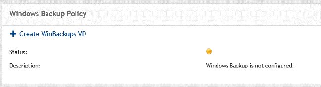
3
Managing Your Appliance
The Core Console includes an Appliance tab, which you can use to provision space, monitor the health
of the appliance, and access management tools.
Monitoring status of the Appliance
You can monitor the status of the Appliance subsystems by using the Appliance → Health page. The
Health page displays a status light next to each subsystem, along with a status description indicating the
health of the subsystem.
The Health page also provides links to tools that drill down into the details of each subsystem, which can
be helpful for troubleshooting warnings or errors. The Provisioning Status link, available for the Storage
Provisioning subsystem, opens the Provisioning screen which displays the provisioning status of that
subsystem. The Rapid Appliance Self Recovery link available for Rapid Appliance Self Recovery
subsystem opens the Backup page, where you can create the RASR USB key, monitor the Windows
backup status, and configure the Windows backup policy. The VM Management link opens the Virtual
Standby page from where you can manage the virtual machines. The Server Administrator link available
for the Storage Hardware subsystem opens the health page of your system where you can analyze the
health of the controller, enclosure, physical drives and so on. The Controllers link, available for Appliance
Hardware opens the Controllers page, which gives the detail of the controllers and the physical drives
associated with the controller.
Windows backup
The Windows backup feature is available in all DL flavors except DL 1000. The Appliance → Backup tab
allows you to configure the Windows backup policy and displays status of the last backup and also the
items that are backed up previously. To use this Windows backup feature, Windows backup virtual disk
must exist.
• After you upgrade your appliance with the latest RUU (3.0.x), and if the Windows backup VD (created
in AppAssure environment) doesn't exist, the Windows Backup virtual disk is created after you
complete the DL Appliance Configuration Wizard. In case, if the Windows backup VD doesn’t exist,
click + Create WinBackups VD on the Backup page under Windows Backup Policy section. In DL
4000 and DL 4300, a VD of size 295 GB is created and in DL1300, a VD of size 210 GB is created.
137

• After you upgrade your appliance with the latest RUU, and if the Windows backup VD created in the
AppAssure environment exists, perform these steps to create Windows backup VD in the RR
environment:
a. Edit ApplianceProvisioningConfiguration.xml (this file is located in the root of each volume, so
you can edit it once and then copy where necessary):
CAUTION: Do not delete existing Windows backup VD.
1. Delete all text between <BackupVolumes> tags.
2. Delete </BackupVolumes> tag.
3. Edit <BackupVolumes> tag, so it will become <Backupvolume/>
4. Save and close.
b. Go to Core Console.
c. Click Appliance → RASR tab.
d. Click Create Windows Backup volume button.
e. Windows backup VD is created if there is enough space.
NOTE: You can also configure Windows Backup using the Windows Server Backup feature and store
backups in any location, but in this case an error is displayed on the RASR page, because backups
cannot be controlled and cannot be guaranteed if they will be consistent to perform restore using
RASR.
Backup Status
Microsoft Windows backup status is available under the Last Backup tab. If a backup is currently running,
the information is displayed under the Current Backup tab. To view the last backup, perform the
following steps:
1. In the Core Console, navigate to the Appliance → Backup tab.
2. Click the arrow beside the Status button to view the status of the backup.
3. The Last Backup pane displays the following information:
• Status
• State
• Backup Location
• Start Time
• End Time
• Error Description
• Items that were backed up
NOTE: The above information is displayed whether the Windows Backup Policy is run or not.
138

If a backup is running, information regarding Current Backup Progress and Start Time is displayed.
Windows Backup Policy
To configure a Windows backup policy, perform the following steps:
1. In the Core Console, navigate to Appliance → Backup.
2. Click the Configure Policy button.
The Windows Backup Policy window is displayed.
3. Enter the parameters as described below:
Text Box Description
Following items
will be backed up: • OS Volume
• Recovery partition
• Bare metal recovery binaries
All of the above are selected by default.
Perform backup Select the frequency at which Winbackup has to be performed. You have the
following options: Daily, Weekly, and Monthly.
Select the time to
schedule the
backup:
Enter the time to schedule a backup.
4. Click Configure.
The Winbackup policy is configured and the details are displayed in the Windows Backup Policy
section.
139
Once configured, you have the option to back up the selected items at any instant using the Backup now
option and delete the backup policy using the Delete policy from the Windows Backup Policy section.
Provisioning storage
The appliance configures available internal storage and any attached supported external storage
enclosures for:
• Repositories\
• Disk volumes for standby VMs or any other purpose
Before you begin provisioning storage on the disk, determine how much storage you want to allocate for
standby virtual machines. You can allocate any percentage of the available capacity remaining after
creating the Rapid Recovery repository to host standby virtual machines. For example, if you are using
Storage Resource Management (SRM), you can allocate up to 100 percent capacity of the storage
remaining after creating the Rapid Recovery repository. Space can be allocated for standby VMs only on
the appliances that are provisioned to host virtual machines. Using the Rapid Recovery’s Live Recovery
feature, you can use these virtual machines to quickly replace a failed server that the appliance protects.
Based on a medium-sized environment that does not need standby virtual machines, you can use all of
the storage to back up a significant number of agents. However, if you need more resources for standby
virtual machines and back up a smaller number of agent machines, you can allocate more resources for
larger VMs.
When you select the Appliance → Provisioning tab, the Rapid Recovery Appliance software locates the
available storage space for all supported controllers in the system and validates that the hardware meets
the requirements.
To complete disk provisioning for all available storage:
1. Click Appliance → Provisioning.
The Provisioning screen displays the Repositories and Storage Volumes sections.
CAUTION: Before proceeding ensure Step 2 through Step 4 is followed in this procedure.
2. Provision available storage to create:
• Repository
• Disk volumes for standby VMs or any other purpose
3. To create a repository:
a. On the provisioning page, in the Repositories section, click Add New Repository
The Add New Repository dialog box appears.
b. Enter the information as described in the following table.
140

Table 56. Provisioning storage
Text Box Description
Repository Name Enter the display name of the repository.
By default, this text box consists of the word Repository and a
number, which corresponds to the number of repositories for this
Core. For example, if this is the second repository, the default name
is Repository 2. Change the name as needed.
Repository names must contain between 1 and 40 alphanumeric
characters, including spaces. Do not use prohibited characters or
prohibited phrases . For more information, see the topics ‘prohibited
characters’ or ‘prohibited phrases’ in the Dell Data Protection | Rapid
Recovery 6.0 User Guide.
Controller Select the appropriate storage controller depending on whether you
are creating repository on internal storage or on direct-attached
storage enclosure.
Enclosure Select the appropriate storage enclosure.
RAID type Select the appropriate RAID level. You have the following options for
RAID configuration: 1, 5, or 6.
NOTE: Your system allows you to create repository only in the
RAID levels in which the storage is configured and as available
out of factory. To create repository in desired RAID
configuration, you must configure your storage in the desired
RAID level. To configure storage in the desired RAID level, see
Dell Adapters documentation at www.dell.com/support/home.
Estimated capacity Displays the estimated capacity available for creating a repository.
Controller available
space
Displays the available space on the controller.
Size Enter the size of the repository.
c. Click Create.
A new repository is created.
4. To create disk volumes for standby VM or any other purpose:
a. In the Storage Volume section, click Create Volume.
b. In the Create Volume dialog box, specify the following information for a new disk volume
Volume name, Controller, Enclosure, RAID type, and Size.
The Controller available space is displayed by default. You can select one of the following RAID
configurations: 1, 5, or 6.
c. Click Create.
A new storage volume is created.
Deleting space allocation for a virtual disk
In case, if you need to change provisioning configuration please contact technical support. For more
information, see Contacting Dell section.
141

Recovery and Update Utility
The Recovery and Update Utility (RUU) is an all-in-one installer to recover and update DL Appliances
(DL1000, DL1300, DL4000 and DL4300) software. It includes the Rapid Recovery Core software and
appliance-specific components.
RUU consists of updated versions of the Windows Server Roles and Features, .Net 4.5.2, LSI Provider, DL
Applications, OpenManage Server Administrator and Rapid Recovery Core Software. In addition, the
Recovery and Update Utility also updates the Rapid Appliance Self Recovery (RASR) content.
NOTE: If you are currently using any of the AppAssure Core versions, Rapid Recovery Core version
6.0.2.144 or earlier, RUU forces an update to the most recent version available in the Payload. It is
not possible to skip the update and this update is not revertible. If you do not want to upgrade the
Core software, do not run the RUU.
Upgrading your Appliance
To upgrade your appliance:
1. Go to the License Portal under the Downloads section or go to support.dell.com and download the
RUU installer.
2. Copy the utility to the appliance desktop and extract the files.
3. Double-click the launchRUU icon.
4. When prompted, click Yes to acknowledge that you are not running any of the listed processes.
5. When the Recovery and Update Utility screen appears, click Start.
6. When prompted to reboot, click OK.
The updated versions of the Windows Server Roles and Features, .Net 4.5.2, LSI Provider, DL
Applications, OpenManage Server Administrator and Rapid Recovery Core Software are installed as
part of the Recovery and Update Utility. In addition to these, the Recovery and Update Utility also
updates the RASR content.
NOTE: If you are currently using any of the AppAssure Core versions, Rapid Recovery Core
version 6.0.2.144 or earlier, RUU forces an update to the most recent version available in the
Payload. It is not possible to skip the update and this update is not revertible. If you do not want
to upgrade the Core software, do not run the RUU.
7. If prompted, reboot your system.
8. After all services and applications are installed, click Proceed.
The Core Console launches.
Repairing your Appliance
To repair your appliance:
1. Go to the License Portal under the Downloads section or go to support.dell.com and download the
RUU installer.
2. Copy the utility to the appliance desktop and extract the files.
3. Double-click the launchRUU icon.
4. When prompted, click Yes to acknowledge that you are not running any of the listed processes.
5. When the Recovery and Update Utility screen displays, click Start.
6. When prompted to reboot, click OK.
142

The updated versions of the Windows Server Roles and Features,.Net 4.5.2, LSI Provider, DL
Applications, OpenManage Server Administrator and Rapid Recovery Core Software are installed as
part of the Recovery and Update Utility.
7. If the bundled version in the utility is the same as the installed version, the Recovery and Update
Utility prompts you to confirm that you want to run a repair installation. This step can be skipped if a
repair install of the Rapid Recovery Core is not needed.
8. If the bundled version in the utility is higher than the installed version, then the Recovery and Update
Utility prompts you to confirm that you want to upgrade the Rapid Recovery Core software.
NOTE: Rapid Recovery Core software downgrades are not supported.
9. If prompted, reboot your system.
10. After all services and applications are installed, click Proceed.
DL Appliance Configuration Wizard will be launched if the system needs to be configured again after
repair, otherwise Core Console will be launched.
143

4
Protecting workstations and servers
Protecting machines
This section describes how to protect, configure, and manage the protected machines in your Rapid
Recovery environment.
About protecting machines with Rapid Recovery
To protect your data using Rapid Recovery, you need to add the workstations and servers for protection
in the Rapid Recovery Core Console; for example, your Exchange server, SQL Server, Linux server, and so
on.
You must install the Rapid Recovery Agent software on all physical or virtual machines you want to
protect in the Core.
NOTE: As an exception to this rule, if protecting virtual machines on a VMware or ESXi host, you can
use agentless protection. For more information, including restrictions for agentless protection, see
Understanding Rapid Snap for Virtual.
In the Rapid Recovery Core Console, using one of the Protect Machine wizards, you can identify the
machines you want to protect. You can do the following:
• You can protect a single machine using the Protect Machine wizard, which connects to the machine
using network hostname or IP address. For more information on how to protect a single machine,
Protecting a machine.
• You can protect a network cluster using the Protect Cluster function, which connects to the cluster
and its nodes using network hostname or IP address.
• You can protect multiple machines simultaneously using the Protect Multiple Machines wizard, which
connects to the machines using Microsoft Active Directory®, or to a vCenter or ESXi host; or you can
specify the network hostname or IP addresses for a list of machines you enter manually.
NOTE: Dell recommends limiting the number of machines you protect simultaneously to 50 or
fewer, to preclude experiencing resource constraints that may cause the protect operation to fail.
When identifying your protection requirements for a single machine in the wizard, you can specify which
volumes to protect. When you protect multiple machines, all volumes are protected by default. (You can
change this later on an individual machine basis).
The wizard also lets you define a customized schedule for protection (or re-use an existing schedule).
Using advanced options, you can add additional security measures by specifying or applying an
encryption key to backups for the machines you want to protect.
Finally, if one does not already exist, you can define a repository using the wizard.
After installing the Agent software, each machine must be restarted after installation.
144

For more information on how to protect workstations and servers, see Protecting a machine.
CAUTION: Rapid Recovery does not support bare metal restore (BMRs) of Linux machines with
ext2 boot partitions. Any BMR performed on a machine with this type of partition results in a
machine that does not start. If you want to be able to perform a BMR on a Linux machine with an
ext2 boot partition, you must convert the ext2 boot partition to ext3 or ext4 before you begin
protecting and backing up the machine.
About protecting Linux machines with Rapid Recovery
The Rapid Recovery Agent software is compatible with multiple Linux-based operating systems (for
details, see the system requirements included in Rapid Recovery Installation and Upgrade Guide or Rapid
Recovery Release Notes). The Rapid Recovery Core is compatible only with Windows machines. While
you can manage protected Linux machines from the Rapid Recovery Core Console, several procedures
for Linux machines have steps that differ from their Windows counterparts. Additionally, you can perform
some actions directly on a protected Linux machine by using the local_mount command line utility.
NOTE: The local_mount utility was formerly called aamount.
About managing Exchange and SQL servers in Rapid Recovery Core
Options specific to Exchange Server and SQL Server appear in the Rapid Recovery Core Console only
when an instance of the software and related files are detected on protected servers. In those cases,
additional options are available when you select the protected machine in the Core Console.
For example, if you select a protected Exchange server in the left navigation menu, then the menu
options that appear for that protected machine include an Exchange drop-down menu option.
If you select a protected SQL server in the left navigation menu, then the menu options that appear for
that protected machine include a SQL drop-down menu.
While these options may work differently, there is some commonality. Functions you can accomplish for
protected Exchange and SQL servers (and for no other protected machines) include:
•Forcing server log truncation. Both SQL servers and Exchange servers include server logs. The
process of truncating SQL logs identifies available space on the server. When you truncate logs for an
Exchange server, in addition to identifying the available space, the process frees up more space on the
server.
•Setting credentials for the relevant server. Exchange servers allow you to set credentials for the
protected machine on the Summary page for the protected server. SQL servers allow you to set
credentials for a single protected SQL Server machine, or to set default credentials for all protected
SQL servers.
•Viewing status for checks on recovery points from Exchange Server or SQL Server. Recovery points
captured from a protected SQL or Exchange server have corresponding color status indicators. These
colors indicate the success or failure of various checks relevant for SQL servers or Exchange servers.
This section includes the following topics specific to managing protected machines that use Exchange
Server or SQL Server:
•Understanding recovery point status indicators
•Settings and functions for protected Exchange servers
•Settings and functions for protected SQL servers
145

About protecting server clusters
In Rapid Recovery, server cluster protection is associated with the Rapid Recovery protected machines
installed on individual cluster nodes (that is, individual machines in the cluster) and the Rapid Recovery
Core, which protects those machines, all as if they were one composite machine.
You can easily configure a Rapid Recovery Core to protect and manage a cluster. In the Core Console, a
cluster is organized as a separate entity, which acts as a container that includes the related nodes. For
example, in the left navigation area, under the Protected Machines menu, protected clusters are listed.
Directly below each cluster, the associated individual nodes or agent machines appear. Each of these is a
protected machine on which the Rapid Recovery Agent software is installed. If you click on the cluster,
the Summary page for the cluster appears in the Core Console.
At the Core and cluster levels, you can view information about the cluster, such as the list of related
nodes and shared volumes. When showing information for a cluster in the Core Console, you can click
Protected Nodes in the top navigation menu to view a summary table of individual nodes in the cluster.
From that summary table, for each node, you can perform functions such as forcing a snapshot;
performing a one-time export or setting up virtual standby; mounting or viewing recovery points;
restoring from a recovery point; converting the cluster node to its own protected machine; or removing
the node from protection. If the node is an Exchange or SQL Server, you will also see the option to
truncate logs.
At the cluster level, you can also view corresponding Exchange and SQL cluster metadata for the nodes
in the cluster. You can specify settings for the entire cluster and the shared volumes in that cluster.
If you click on any node in the cluster from the left navigation menu, the information displayed in the
Core Console is specific to that node of the cluster. Here you can view information specific to that node,
or configure settings just for that node.
Support for cluster shared volumes
In Rapid Recovery release 6.x, support for cluster-shared volumes (CSV) is limited to native backup of
CSVs running Windows Server 2008 R2. You can also restore CSV volumes running Windows Server 2008
R2 from a recovery point, or perform virtual export to a Hyper-V CSV running Windows Server 2008 R2.
You cannot perform virtual export of a cluster-shared volume. New in Rapid Recovery release 6.0.1 and
later is the ability to perform virtual export to a Hyper-V CSV running Windows Server 2012 or Windows
Server 2012 R2.
NOTE: The Hyper-V agentless feature is compatible only with Windows Server 2012 R2 and later.
For other operating systems, the Rapid Recovery Agent service can be run on all nodes in a cluster, and
the cluster can be protected as a cluster within the Rapid Recovery Core; however, CSVs do not display in
the Core Console and are not available for protection. All local disks (such as the operating system
volume) are available for protection.
The following table depicts current support in Rapid Recovery Core for cluster-shared volumes.
146

Table 57. Rapid Recovery support for cluster-shared volumes
Rapid Recovery Cluster Shared Volumes Support Protect,
Replicate,
Rollup, Mount,
Archive
Restore CSV
Volumes Virtual Export
to Hyper-V
CSV
Rapid Recovery 6.0 6.0 6.0.x
Windows Server 2008 R2 Yes Yes Yes
Windows Server 2012 No No Yes
Windows Server 2012 R2 No No Yes
1 Excludes the Hyper-V agentless feature, which is compatible only with Windows Server 2012 R2 and
later.
While Rapid Recovery may let you protect some other operating systems on cluster-shared volumes, you
do so at your own risk. Only the configurations in the table above are supported by Dell.
Support for dynamic and basic volumes
Rapid Recovery supports taking snapshots of all dynamic and basic volumes. Rapid Recovery also
supports exporting simple dynamic volumes that are on a single physical disk. As their name implies,
simple dynamic volumes are not striped, mirrored, spanned, or RAID volumes.
The behavior for virtual export of dynamic disks differs, based on whether the volume you want to export
is protected by the Rapid Recovery Agent software, or is a VM using agentless protection. This is because
non-simple or complex dynamic volumes have arbitrary disk geometries that cannot be fully interpreted
by the Rapid Recovery Agent.
When you try to export a complex dynamic disk from a machine with the Rapid Recovery Agent software,
a notification appears in the user interface to alert you that exports are limited and restricted to simple
dynamic volumes. If you attempt to export anything other than a simple dynamic volume with the Rapid
Recovery Agent, the export job fails.
In contrast, dynamic volumes for VMs you protect agentlessly are supported for protection, virtual export,
restoring data, and BMR, and for repository storage, with some important restrictions. For example:
•Protection: In the case when a dynamic volume spans multiple disks, you must protect those disks
together to maintain the integrity of the volume.
•Virtual export: You can export complex dynamic volumes such as striped, mirrored, spanned, or RAID
volumes from an ESXi host using agentless protection.
However, the volumes are exported at the disk level, with no volume parsing. For example, if
exporting a dynamic volume spanned across two disks, the export will include two distinct disk
volumes.
CAUTION: When exporting a dynamic volume that spans multiple disks, you must export the
dynamic disks with the original system volumes to preserve the disk types.
•Restoring data: When restoring a dynamic volume that spans multiple disks, you must restore the
dynamic disks with the original system volumes to preserve the disk types. If you restore only one disk,
you will break the disk configuration.
147

Repository storage: Additionally, Rapid Recovery supports the creation of repositories on complex
dynamic volumes (striped, mirrored, spanned, or RAID). The file system of the machine hosting the
repository must be NTFS or ReFS.
Understanding the Rapid Recovery Agent software installer
Rapid Recovery lets you download installers from the Rapid Recovery Core. From the Downloads page,
you can choose to download the Agent Installer, the Local Mount Utility (LMU), or an SNMP MIB file. For
more information about the LMU, see The Local Mount Utility. For more information about SNMP, see
Understanding SNMP settings.
NOTE: For access to the Agent Installer, see Downloading the Rapid Recovery Agent Installer. For
more information about deploying the Agent Installer, see the Dell Data Protection | Rapid Recovery
Installation and Upgrade Guide.
The Agent installer is used to install the Rapid Recovery Agent application on machines that are intended
to be protected by the Rapid Recovery Core. If you determine that you have a machine that requires the
Agent Installer, you can download the web installer from the Downloads page of the Rapid Recovery
Core Console.
NOTE: Downloading of the Core is performed from the Dell Data Protection | Rapid Recovery
License Portal. To download the Rapid Recovery Core installer, visit https://licenseportal.com. For
more information, see the Dell Data Protection | Rapid Recovery License Portal User Guide.
Downloading the Rapid Recovery Agent Installer
Download the Rapid Recovery Agent Installer and deploy it to any machine that you want to protect on
the Rapid Recovery Core. Complete the steps in this procedure to download the web installer.
1. To download the Agent web installer directly from the machine you want to protect, do the
following:
a. In a web browser, open the Dell Data Protection | Rapid Recovery License Portal at https://
licenseportal.com.
b. From the left navigation menu, click Downloads.
c. From the Windows-Based Applications pane, scroll down to the Windows Agent row, and click
Download for the appropriate installer (32-bit or 64-bit systems).
The installer file, for example Agent-X64-6.0.1.xxxx.exe, saves to the downloads destination
folder.
2. To download the web installer from the Core, on the Core Console icon bar, click the More
icon and then select Downloads.
3. On the Downloads page, from the Agent pane, click Download web installer.
4. From the Opening Agent-Web.exe dialog box, click Save File.
The installer file, for example Agent-X64-6.0.1.xxxx.exe, saves to the downloads destination
folder.
5. Move the installer to the appropriate machine and install the Rapid Recovery Agent software.
For more information about installing the Rapid Recovery Agent software, see the Rapid Recovery
Installation and Upgrade Guide.
148

Deploying Agent to multiple machines simultaneously from the Core Console
You can deploy the Rapid Recovery Agent software simultaneously to multiple Windows machines. The
machines can be part of an Active Directory domain or vCenter or ESX(i) virtual host; or they can be
machines already protected by the local Rapid Recovery Core, as in the case of a Rapid Recovery Agent
software upgrade. You also have the option to manually deploy the software to machines that are not
necessarily associated with a specific domain or host.
You can also manually deploy the Rapid Recovery Agent software to one or more Linux machines from
the Core Console.
CAUTION: If AppAssure Agent was previously installed on a Linux machine, then before installing
Rapid Recovery Agent, remove the AppAssure Agent from the machine using a shell script. For
information on removing the Agent from a Linux machine, see the topic Uninstalling the
AppAssure Agent software from a Linux machine. To successfully deploy the Agent software to
Linux machines, see the prerequisites in the topic About installing the Agent software on Linux
machines. These topics are found in the Dell Data Protection | Rapid Recovery Installation and
Upgrade Guide.
Deploying the Rapid Recovery Agent software does not protect the machines automatically. After
deploying, you must then select the Protect Multiple Machines option from the button bar of the Core
Console.
NOTE: The feature in which you deploy to multiple machines simultaneously was previously
referred to as “bulk deploy”. The feature in which you protect multiple machines simultaneously was
previously referred to as “bulk protect”.
To deploy and protect multiple machines simultaneously, perform the following tasks:
• Deploy Rapid Recovery Agent to multiple machines. See Deploying the Rapid Recovery Agent
software to one or more machines.
• Monitor the deployment. See Verifying the deployment to multiple machines.
• Protect multiple machines. See About protecting multiple machines.
NOTE: If you selected the Protect Machine After Install option during deployment, skip this task.
• Monitor the activity of the bulk protection. See Monitoring the protection of multiple machines.
Deploying the Rapid Recovery Agent software to one or more machines
You can simplify the task of deploying the Rapid Recovery Agent software to one or more Windows
machines by using the Deploy Agent Software Wizard.
NOTE: In the past, this feature was referred to as "bulk deploy."
When you use the Deploy Agent Software Wizard, Rapid Recovery can automatically detect machines on
a host and let you select the machines to which you want to deploy. For machines on domains or hosts
other than Active Directory or vCenter or ESX(i), you can manually connect to individual machines by
using their IP addresses and the appropriate credentials. You can also push upgrades of the software to
machines that the local Rapid Recovery Core already protects.
From within the Core Console, you can complete any of the following tasks:
•Deploying to machines on an Active Directory domain
149

•Deploying to machines on a VMware vCenter/ESX(i) virtual host
•Deploying an upgrade of the Rapid Recovery Agent software to protected machines
•Deploying to machines manually
NOTE: Dell recommends limiting the number of machines to which you deploy simultaneously to
50 or fewer, to preclude experiencing resource constraints that may cause the deploy operation to
fail.
NOTE: The target machines must have internet access to download and install bits, because Rapid
Recovery uses the web version of the Rapid Recovery Agent Installer to deploy the installation
components. If internet access is unavailable, use the Core Console to download the installer to a
medium, such as a USB drive, and then physically install the software on the machines that you
want to protect. For more information, see Downloading the Rapid Recovery Agent Installer.
Deploying to machines on an Active Directory domain
Use this procedure to simultaneously deploy the Rapid Recovery Agent software to one or more
machines on an Active Directory domain.
Before you begin this procedure, have the domain information and logon credentials for the Active
Directory server on hand.
1. On the Rapid Recovery Core Console, click the Protect drop-down menu, and then click Deploy
Agent Software.
The Deploy Agent Software Wizard opens.
2. On the Connection page of the wizard, from the Source drop-down list, select Active Directory.
3. Enter the domain information and logon credentials as described in the following table.
Table 58. Domain information and credentials
Text Box Description
Host The host name or IP address of the Active Directory domain.
User name The user name used to connect to the domain; for example, Administrator or, if
the machine is in a domain, [domain name]\Administrator).
Password The secure password used to connect to the domain.
4. Click Next.
5. On the Machines page, select the machines to which you want to deploy the Rapid Recovery Agent
software.
6. Optionally, to automatically restart the protected machines after the Agent is installed, select After
Agent installation, restart the machines automatically (Recommended).
7. Click Finish.
The system automatically verifies each machine that you selected.
If Rapid Recovery detects any concerns during automatic verification, the wizard progresses to a
Warnings page, where you can clear machines from selection and manually verify the selected
machines. If the machines you added pass the automatic verification, they appear on the Deploy
Agent to Machines pane.
8. If the Warning page appeared and you are still satisfied with your selections, click Finish again.
The Rapid Recovery Agent software deploys to the specified machines. The machines are not yet
protected. Protection begins after you complete Protecting multiple machines on an Active Directory
domain.
150

Deploying to machines on a VMware vCenter/ESX(i) virtual host
Use this procedure to simultaneously deploy the Rapid Recovery Agent software to one or more
machines on a VMware vCenter/ESX(i) virtual host.
Before starting this procedure, you must have the following information:
• Logon credentials for the VMware vCenter/ESX(i) virtual host.
• Host location.
• Logon credentials for each machine you want to protect.
NOTE: All virtual machines must have VMware Tools installed; otherwise, Rapid Recovery cannot
detect the host name of the virtual machine to which to deploy. In lieu of the host name, Rapid
Recovery uses the virtual machine name, which may cause issues if the host name is different from
the virtual machine name.
1. On the Rapid Recovery Core Console, click the Protect drop-down menu, and then click Deploy
Agent Software.
The Deploy Agent Software Wizard opens.
2. On the Connection page of the wizard, from the Source drop-down list, select vCenter / ESX(i).
3. Enter the host information and logon credentials as described in the following table.
Table 59. vCenter/ESX(i) connection settings
Text Box Description
Host The name or IP address of the VMware vCenter Server/ESX(i) virtual host.
Port The port used to connect to the virtual host.
The default setting is 443.
User name The user name used to connect to the virtual host; for example, Administrator or, if
the machine is in a domain, [domain name]\Administrator.
Password The secure password used to connect to this virtual host.
4. Click Next.
5. On the Machines page of the wizard, select one of the following options from the drop-down menu:
• Hosts and Clusters
• VMs and Templates
6. Expand the list of machines, and then select the VMs to which you want to deploy the software.
A notification appears if Rapid Recovery detects that a machine is offline or that VMware Tools are
not installed.
7. If you want to restart the machines automatically after deployment, select After Agent installation,
restart the machines automatically (Recommended).
8. Click Next.
Rapid Recovery automatically verifies each machine you selected.
9. On the Adjustments page of the wizard, enter the credentials for each machine in the following
format: hostname::username::password.
NOTE: Enter one machine on each line.
10. Click Finish.
The system automatically verifies each machine that you selected.
If Rapid Recovery detects any concerns during automatic verification, the wizard progresses to a
Warnings page, where you can clear machines from selection and manually verify the selected
151

machines. If the machines you added pass the automatic verification, they appear on the Deploy
Agent to Machines pane.
11. If the Warning page appeared and you are still satisfied with your selections, click Finish again.
The Rapid Recovery Agent software deploys to the specified machines. The machines are not yet
protected. Protection begins after you complete Protecting multiple machines on a VMware vCenter/
ESX(i) virtual host.
Deploying an upgrade of the Rapid Recovery Agent software to protected machines
You can use the Deploy Agent Software Wizard to push an upgrade of the Rapid Recovery Agent software
to machines that are already protected by the local Rapid Recovery Core.
1. On the Rapid Recovery Core Console, click the Protect drop-down menu, and then click Deploy
Agent Software.
The Deploy Agent Software Wizard opens.
2. On the Connection page of the wizard, from the Source drop-down list, select Local Core.
3. Click Next.
4. On the Machines page of the wizard, select the protected machines to which you want to deploy an
upgrade of the Rapid Recovery Agent software.
5. Click Finish.
The system automatically verifies each machine that you selected.
If Rapid Recovery detects any concerns during automatic verification, the wizard progresses to a
Warnings page, where you can clear machines from selection and manually verify the selected
machines. If the machines you added pass the automatic verification, they appear on the Deploy
Agent to Machines pane.
6. If the Warning page appeared, and you are still satisfied with your selections, click Finish again.
Deploying to machines manually
Use the following procedure to deploy the Rapid Recovery Agent to multiple machines on any type of
host other than the local Core, Active Directory, or vCenter/ESXi.
1. On the Rapid Recovery Core Console, click the Protect drop-down menu, and then select Deploy
Agent Software.
The Deploy Agent Software Wizard opens.
2. On the Connection page of the wizard, from the Source drop-down list, select Manually.
3. Click Next.
4. On the Machines page of the wizard, enter the machine details in the dialog box in the format
hostname::username::password::port. Examples include:
10.255.255.255::administrator::&11@yYz90z::8006
abc-host-00-1::administrator::99!zU$o83r::168
5. If you want to restart the machines automatically after deployment, select After Agent installation,
restart the machines automatically (Recommended).
6. Click Finish.
The system automatically verifies each machine that you selected.
If Rapid Recovery detects any concerns during automatic verification, the wizard progresses to a
Warnings page, where you can clear machines from selection and manually verify the selected
machines. If the machines you added pass the automatic verification, they appear on the Deploy
Agent to Machines pane.
7. If the Warning page appeared, and you are still satisfied with your selections, click Finish again.
152
The Rapid Recovery Agent software deploys to the specified machines. The machines are not yet
protected. Protection begins after you complete Protecting multiple machines manually.
Verifying the deployment to multiple machines
Once you have deployed the Rapid Recovery Agent software to two or more machines simultaneously,
you can verify the success by viewing each machine listed under the Protected Machines menu.
You can also view information regarding the bulk deploy process from the Events page. Complete the
steps in this procedure to verify the deployment.
1. Navigate to the Rapid Recovery Core Console, click (Events), and then click Alerts.
Alert events appear in the list, showing the time the event initiated and a message. For each
successful deployment of the Agent software, you will see an alert indicating that the protected
machine has been added.
2. Optionally, click on any link for a protected machine.
The Summary page for the selected machine appears, showing pertinent information including:
• The host name of the protected machine
• The last snapshot, if applicable
• The time of the next scheduled snapshot, based on the protection schedule for the selected
machine
• The encryption key, if any, used for this protected machine.
• The version of the Agent software.
Modifying deploy settings
Complete the steps in this procedure to modify deploy settings.
1. From the Rapid Recovery Core Console, click (Settings).
2. On the Settings page, in the left column, click Deploy to navigate to the Deploy section.
3. Modify any of the following options by clicking the setting you want to change to make it editable as
a text box or drop-down list, and then click to save the setting.
Table 60. Deploy options
Option Description
Agent Installer
Name
Enter the name of the agent executable file. The default is Agent-web.exe.
Core Address Enter the address for the Core.
Failed Receive
Timeout
Enter the number of minutes to wait without activity before timeout.
Maximum
Parallel Installs
Enter a number for the maximum installations you want to install simultaneously.
The default and limit is 100.
Automatic
reboot after
install
Select the check box for Yes, or clear it for No.
153

Option Description
Protect After
Deploy
Select the check box for Yes, or clear it for No.
Understanding protection schedules
A protection schedule defines when backups are transferred from protected agent machines to the Rapid
Recovery Core.
The first backup transfer saved to the Core is called a base image snapshot. All data on all specified
volumes (including the operating system, applications, and settings), are saved to the Core, which can
take a significant amount of time depending on the amount of data being transferred. Thereafter,
incremental snapshots (smaller backups, consisting only of data changed on the protected machine since
the last backup) are saved to the Core regularly, based on the interval defined (for example, every 60
minutes). This backup contains less data than a base image, and therefore takes a shorter amount of time
to transfer.
Protection schedules are initially defined using the Protect Machine Wizard or the Protect Multiple
Machines Wizard. Using a wizard, you can customize protection schedules (choosing either periods or a
daily protection time) to accommodate your business needs. You can then modify the existing schedule
or create a new schedule at any time in the Protection Schedule dialog box from the summary page of a
specific protected machine.
Rapid Recovery provides a default protection schedule, which includes a single period spanning all days
of the week, with a single time period defined (from 12:00 AM to 11:59 PM). The default interval (the time
period between snapshots) is 60 minutes. When you first enable protection, you also activate the
schedule. Thus, using the default settings, regardless of the current time of day, the first backup will occur
every hour, on the hour (12:00 AM, 1:00 AM, 2:00 AM, and so on).
Selecting periods lets you view the default protection schedule and make adjustments accordingly.
Selecting a daily protection time causes Rapid Recovery Core to back up the designated protected
machines once daily at a time you specify.
You can customize the schedule to define peak and off-peak times using the weekday and weekend
periods available. For example, if your protected machines are mostly in use on weekdays, you could
decrease the interval for the weekday period to 20 minutes, resulting in three snapshots every hour. Or
you can increase the interval for the weekend period from 60 minutes to 180 minutes, resulting in
snapshots once every three hours when traffic is low.
Alternatively, you can change the default schedule to define peak and off-peak times daily. To do this,
change the default start and end time to a smaller range of time (for example, 12:00 AM to 4:59 PM), and
set an appropriate interval (for example, 20 minutes). This represents frequent backups during peak
periods. You can then add an additional weekday time range for the remaining span of time (5:00 pm to
11:59 pm) and set an appropriate (presumably larger) interval (for example, 180 minutes). These settings
define an off-peak period that includes 5:00 PM to midnight every day. This customization results in
snapshots every three hours from 5:00 PM through 11:59 PM, and snapshots every 20 minutes from
12:00 AM until 4:59 PM.
When you modify or create a protection schedule using the Protection Schedule dialog box, Rapid
Recovery gives you the option to save that schedule as a reusable template that you can then apply to
other protected machines.
154

Other options in the protection wizards include setting a daily protection time. This results in a single
backup daily at the period defined (the default setting is 12:00 PM).
When protecting one or multiple machines using a wizard, you can initially pause protection, which
defines the protection schedule without protecting the machines. When you are ready to begin
protecting your machines based on the established protection schedule, you must explicitly resume
protection. For more information on resuming protection, see Pausing and resuming protection.
Optionally, if you want to protect a machine immediately, you can force a snapshot. For more
information, see Forcing a snapshot.
Protecting a machine
If you have already installed the Rapid Recovery Agent software on the machine you want to protect, but
have not restarted it yet, restart the machine now.
This topic describes how to start protecting the data on a single machine that you specify using the
Protect Machine Wizard.
NOTE: Unless using agentless protection on a VMware or ESXi host, the machine you want to
protect must have the Rapid Recovery Agent software installed in order to be protected. You can
choose to install the Agent software prior to this procedure, or you can deploy the software to the
target machine as a part of completing the Protect Machine Wizard.
For more information on agentless protection and its restrictions, see Understanding Rapid Snap for
Virtual.
For more information on installing the Agent software, see “Installing the Rapid Recovery Agent
software” in the Dell Data Protection | Rapid Recovery License Portal Installation and Upgrade
Guide.
If the Agent software is not installed prior to protecting a machine, you will not be able to select
specific volumes for protection as part of this wizard. In this case, by default, all volumes on the
agent machine will be included for protection.
Rapid Recovery supports the protection and recovery of machines configured with EISA partitions.
Support is also extended to Windows 8 and 8.1, and Windows 2012 and 2012 R2 machines that use
Windows Recovery Environment (Windows RE).
To protect multiple machines using one process simultaneously, see About protecting multiple machines.
When you add protection, you need to define connection information such as the IP address and port,
and provide credentials for the machine you want to protect. Optionally, you can provide a display name
to appear in the Core Console instead of the IP address. If you change this, you will not see the IP address
for the protected machine when you view details in the Core Console. You will also define the protection
schedule for the machine.
The protection process includes optional steps you can access if you select an advanced configuration.
Advanced options include repository functions and encryption. For example, you can specify an existing
Rapid Recovery repository to save snapshots, or create a new repository. You can also specify an existing
encryption key (or add a new encryption key) to apply to the data saved to the Core for this machine. For
more information about encryption keys, see Understanding encryption keys.
The workflow of the protection wizard may differ slightly based on your environment. For example, if the
Rapid Recovery Agent software is installed on the machine you want to protect, you will not be prompted
155

to install it from the wizard. Likewise, if a repository already exists on the Core, you will not be prompted
to create one.
CAUTION: Rapid Recovery does not support bare metal restores (BMRs) of Linux machines with
ext2 boot partitions. Any BMR performed on a machine with this type of partition results in a
machine that does not start. If you want to be able to perform a BMR on this machine in the
future, you must convert any ext2 partitions to ext3 or ext4 before you begin protecting and
backing up the machine.
1. Do one of the following:
• If you are starting from the Protect Machine Wizard, proceed to Step 2.
• If you are starting from the Rapid Recovery Core Console, from the button bar, click Protect.
The Protect Machine Wizard appears.
2. On the Welcome page, select the appropriate installation options:
• If you do not need to define a repository or establish encryption, select Typical.
• If you need to create a repository, or define a different repository for backups for the selected
machine, or if you want to establish encryption using the wizard, select Advanced (show optional
steps).
• Optionally, if you do not wish to see the Welcome page for the Protect Machine Wizard in the
future, select the option Skip this Welcome page the next time the wizard opens.
3. When you are satisfied with your choices on the Welcome page, then click Next.
The Connection page appears.
4. On the Connection page, enter the information about the machine to which you want to connect as
described in the following table, and then click Next.
Table 61. Machine connection settings
Text Box Description
Host The host name or IP address of the machine that you want to protect.
Port The port number on which the Rapid Recovery Core communicates with the
Agent on the machine.
The default port number is 8006.
User name The user name used to connect to this machine; for example, Administrator (or, if
the machine is in a domain, [domain name]\Administrator).
Password The password used to connect to this machine.
If the Install Agent page appears next in the Protect Machine Wizard, that means that Rapid Recovery
does not detect the Rapid RecoveryAgent on the machine and will install the current version of the
software. Go to Step 7.
If the Upgrade Agent page appears next in the wizard, that means that an older version of the Agent
software exists on the machine you want to protect.
NOTE: The Agent software must be installed on the machine you want to protect, and that
machine must be restarted, before it can back up to the Core. To have the installer reboot the
protected machine, select the option After installation, restart the machine automatically
(recommended) before clicking Next.
5. On the Upgrade Agent page, do one of the following:
• To deploy the new version of the Agent software (matching the version for the Rapid Recovery
Core), select Upgrade the Agent to the latest version of the software.
156

• To continue protecting the machine without updating the Agent software version, clear the
option Upgrade the Agent to the latest version of the software.
6. Click Next.
7. Optionally, on the Protection page, if you want a name other than the IP address to display in the
Rapid Recovery Core console for this protected machine, then in the Display Name field, type a
name in the dialog box.
You can enter up to 64 characters. Do not use the special characters described in the topic
prohibited characters . Additionally, do not begin the display name with any of the character
combinations described in the topic prohibited phrases .
8. Select the appropriate protection schedule as described below:
• To use the default protection schedule, in the Schedule Settings option, select Default
protection.
With a default protection schedule, the Core will take snapshots of all volumes on the protected
machine once every hour. To change the protection settings at any time after you close the wizard,
including choosing which volumes to protect, go to the Summary page for the specific protected
machine.
• To define a different protection schedule, in the Schedule Settings option, select Custom
protection.
9. Proceed with your configuration as follows:
• If you selected a Typical configuration for the Protect Machine Wizard and specified default
protection, then click Finish to confirm your choices, close the wizard, and protect the machine
you specified.
The first time protection is added for a machine, a base image (that is, a snapshot of all the data in
the protected volumes) will transfer to the repository on the Rapid Recovery Core following the
schedule you defined, unless you specified to initially pause protection.
• If you selected a Typical configuration for the Protect Machine Wizard and specified custom
protection, then click Next to set up a custom protection schedule. For details on defining a
custom protection schedule, see Creating custom protection schedules.
• If you selected Advanced configuration for the Protect Machine Wizard, and default protection,
then click Next and proceed to Step 14 to see repository and encryption options.
• If you selected Advanced configuration for the Protect Machine Wizard and specified custom
protection, then click Next and proceed to Step 11 to choose which volumes to protect.
10. On the Protection Volumes page, select which volumes you want to protect. If any volumes are
listed that you do not want to include in protection, click in the Check column to clear the selection.
Then click Next.
NOTE: Typically, it is good practice to protect, at minimum, the System Reserved volume and
the volume with the operating system (typically the C drive).
11. On the Protection Schedule page, define a custom protection schedule and then click Next. For
details on defining a custom protection schedule, see Creating custom protection schedules.
If you already have repository information configured, and you selected the Advanced option in Step
1, then the Encryption page appears. Proceed to Step 13.
12. On the Repository page, the following:
• If you already have a repository and want to store the data from this machine for protection in the
existing repository, then do the following:
1. Select Use an existing repository.
2. Select an existing repository from the list.
3. Click Next.
157

The Encryption page appears. Skip to Step 13 to optionally define encryption.
• If you want to create a repository, select Create a Repository, and then complete the following
steps.
1. On the Repository, enter the information described in the following table.
Table 62. Add New Repository settings
Text Box Description
Repository
Name
Enter the display name of the repository.
By default, this text box consists of the word Repository and a number,
which corresponds to the number of repositories for this Core. For
example, if this is the first repository, the default name is Repository 1.
Change the name as needed.
Repository names must contain between 1 and 40 alphanumeric
characters, including spaces. Do not use prohibited characters or prohibited
phrases .
Concurrent
Operations
Define the number of concurrent requests you want the repository to
support. By default the value is 64.
Comments Optionally, enter a descriptive note about this repository. You can enter up
to 254 characters. For example, type DVM Repository 2.
2. Click Add Storage Location to define the specific storage location or volume for the
repository. This volume should be a primary storage location.
CAUTION: Define a dedicated folder within the root for the storage location for your
repository. Do not specify the root location. For example, use E:\Repository\, not E:\.
If the repository that you are creating in this step is later removed, all files at the
storage location of your repository are deleted. If you define your storage location at
the root, all other files in the volume (e.g., E:\) are deleted, which could result in
catastrophic data loss.
The Add Storage Location dialog box appears.
3. Click Add Storage Location to define the specific storage location or volume for the
repository. This volume should be a primary storage location.
4. In the Storage Location area, specify how to add the file for the storage location. You can
choose to add a locally attached storage volume (such as direct attached storage, a storage
area network, or network attached storage). You could also specify a storage volume on a
Common Internet File System (CIFS) shared location.
– Select Add file on local disk to specify a local machine, and then enter the information as
described in the following table.
Table 63. Local disk settings
Text Box Description
Data path Enter the location for storing the protected data.
For example, type X:\Repository\Data.
When specifying the path, use only alphanumeric characters, the
hyphen, and the period (only to separate host names and domains). You
can use the backslash character only to define levels in the path. Do not
use spaces. No other symbols or punctuation characters are permitted.
Metadata
path
Enter the location for storing the protected metadata.
For example, type X:\Repository\Metadata.
158

Text Box Description
When specifying the path, use only alphanumeric characters, the
hyphen, and the period (only to separate host names and domains). You
can use the backslash character only to define levels in the path. Do not
use spaces. No other symbols or punctuation characters are permitted.
– Or, select Add file on CIFS share to specify a network share location, and then enter the
information as described in the following table.
Table 64. CIFS share credentials
Text Box Description
UNC path Enter the path for the network share location.
If this location is at the root, define a dedicated folder name (for
example, Repository).
The path must begin with \\. When specifying the path, use only
alphanumeric characters, the hyphen, and the period (only to separate
host names and domains). The letters a to z are case-insensitive. Do not
use spaces. No other symbols or punctuation characters are permitted.
User name Specify a user name for accessing the network share location.
Password Specify a password for accessing the network share location.
5. In the Storage Configuration area, click More Details and enter the details for the storage
location as described in the following table.
Table 65. Storage configuration details
Text Box Description
Size Set the size or capacity for the storage location. The minimum size is 1 GB.
The default is 250 GB. You can choose from the following:
– GB
– TB
NOTE: The size that you specify cannot exceed the size of the
volume.
If the storage location is a New Technology File System (NTFS) volume
using Windows XP or Windows 7, the file size limit is 16 TB.
If the storage location is a NTFS volume using Windows 8, 8.1, Windows
10, or Windows Server 2012, 2012 R2, the file size limit is 256 TB.
NOTE: For Rapid Recovery to validate the operating system,
Windows Management Instrumentation (WMI) must be installed on
the intended storage location.
Write caching
policy
The write caching policy controls how the Windows Cache Manager is used
in the repository and helps to tune the repository for optimal performance
on different configurations.
Set the value to one of the following:
– On
– Off
– Sync
If set to On, which is the default, Windows controls the caching. This is
appropriate for Windows 10, and for versions of Windows Server 2012
and later.
159

Text Box Description
NOTE: Setting the write caching policy to On could result in faster
performance. If you are using Windows Server 2008 SP2 or
Windows Server 2008 R2 SP2, the recommended setting is Off.
If set to Off, Rapid Recovery controls the caching.
If set to Sync, Windows controls the caching as well as the synchronous
input/output.
Bytes per
sector
Specify the number of bytes you want each sector to include. The default
value is 512.
Average bytes
per record
Specify the average number of bytes per record. The default value is 8192.
6. Click Next.
If you chose the Advanced option in Step 1, the Encryption page appears.
13. Optionally, on the Encryption page, to enable encryption, select Enable Encryption.
Encryption key fields appear on the Encryption page.
NOTE: If you enable encryption, it will be applied to data for all protected volumes for this
machine.
You can change encryption settings later from the Rapid Recovery Core Console.
For more information about encryption, see the topic Understanding encryption keys.
CAUTION: Rapid Recovery uses AES 256-bit encryption in the Cipher Block Chaining (CBC)
mode with 256-bit keys. While using encryption is optional, Dell highly recommends that you
establish an encryption key, and that you protect the passphrase you define. Store the
passphrase in a secure location as it is critical for data recovery. Without a passphrase, data
recovery is not possible.
14. On the Encryption page, select one of the following options:
• If you want to encrypt this protected machine using an encryption key that is already defined on
this Rapid Recovery Core, select Encrypt data using an existing Encryption key, and then select
the appropriate key from the drop-down menu. Proceed to the next step.
• If you want to add a new encryption key to the Core and apply that key to this protected
machine, then enter the information as described in the following table.
Table 66. Encryption key settings
Text Box Description
Name Enter a name for the encryption key.
Encryption key names must contain between 1 and 130 alphanumeric
characters. You may not include special characters such as the back slash,
forward slash, pipe, colon, asterisk, quotation mark, question mark, open or
close brackets, ampersand or hash.
Description Enter a comment for the encryption key.
This information appears in the Description field when viewing encryption keys
from the Core Console.
Passphrase Enter the passphrase used to control access.
Best practice is to avoid special characters listed above.
160

Text Box Description
Record the passphrase in a secure location. Dell Support cannot recover a
passphrase. Once you create an encryption key and apply it to one or more
protected machines, you cannot recover data if you lose the passphrase.
Confirm
Passphrase
Re-enter the passphrase you just entered.
15. Click Finish to save and apply your settings.
The first time protection is added for a machine, a base image (that is, a snapshot of all the data in
the protected volumes) will transfer to the repository on the Rapid Recovery Core following the
schedule you defined, unless you specified to initially pause protection.
Protecting a cluster
This topic describes how to add a cluster for protection in Rapid Recovery . When you add a cluster to
protection, you need to specify the host name or IP address of the cluster, the cluster application, or one
of the cluster nodes or machines that includes the Rapid Recovery Agent software.
NOTE: A repository is used to store the snapshots of data that are captured from your protected
nodes. Before you start protecting data in your cluster, you should have set up at least one
repository that is associated with your Rapid Recovery Core.
For information about setting up repositories, see Understanding repositories.
1. From the Rapid Recovery Core Console, click the Protect button drop-down menu, and then click
Protect Cluster.
2. In the Connect to Cluster dialog box, enter the following information.
Table 67. Connect to Cluster settings
Text Box Description
Host The host name or IP address of the cluster, the cluster application, or one of the
cluster nodes.
Port The port number on the machine on which the Rapid Recovery Core
communicates with the Agent.
The default port is 8006.
User name The user name of the domain administrator used to connect to this machine: for
example, domain_name\administrator.
NOTE: The domain name is mandatory. You cannot connect to the cluster
using the local administrator user name.
Password The password used to connect to this machine.
3. Click Connect.
4. In the Protect Cluster dialog box, select a repository for this cluster.
5. If you want to secure the recovery points for this cluster using Core-based encryption, select an
encryption key.
6. If you do not want protection to begin immediately after completing this procedure, select Initially
pause protection.
7. To protect the cluster based on default settings, select the nodes for default protection, and then go
to Step 10.
161

NOTE: The default settings schedule a snapshot of all volumes every 60 minutes.
8. To enter custom settings for the cluster (for example, to customize the protection schedule for the
shared volumes), do one of the following, and then see Creating custom protection schedules.
• To customize settings for an individual node, next to the node that you want to customize, click
Settings, and then click Function next to the relevant volume.
• To customize settings for the cluster, click the Settings button at the bottom of the dialog box,
and then click Function next to the relevant volume.
For more information about customizing nodes, see Protecting nodes in a cluster.
9. When you have made all necessary changes, click Save.
10. In the Protect Cluster dialog box, click Protect.
Modifying cluster node settings
Once you have added protection for cluster nodes, you can easily modify basic configuration settings for
those machines or nodes (for example, display name, host name, and so on), protection settings (for
example, changing the protection schedule for local volumes on the machine, adding or removing
volumes, and pausing protection), and more.
To modify cluster node settings, you must perform the following tasks:
• In the Rapid Recovery Core Console, navigate to the cluster that contains the node you want to
modify, and select the machine or node that you want to modify.
• To modify and view configuration settings, see Configuring notification groups.
• To configure notification groups for system events, see Viewing and modifying protected machine
settings.
• To customize retention policy settings, see Customizing retention policy settings for a protected
machine.
• To modify the protection schedule, see Modifying protection schedules.
• To modify transfer settings, see About modifying transfer settings.
Protecting nodes in a cluster
This task requires that you first protect a cluster. For more information, see Protecting a cluster.
This topic describes how to protect the data on a cluster node or machine that has a Rapid Recovery
Agent installed. This procedure lets you add individual nodes to protection that you may have omitted
when you protected a cluster.
1. In the Rapid Recovery Core Console, under Protected Machine, click the cluster with the nodes that
you want to protect.
2. On the Summary page for the cluster, click the Protected Nodes.
3. On the Protected Nodes page, click Protect Cluster Node.
4. In the Protect Cluster Node dialog box, select or enter as appropriate the following information.
Table 68. Protect Cluster Node settings
Text Box Description
Host A drop-down list of nodes in the cluster available for protection.
Port The port number on which the Rapid Recovery Core communicates with the Agent on
the node.
162
Text Box Description
User
name
The user name of the domain administrator used to connect to this node; for example,
example_domain\administrator or administrator@example_domain.com.
Password The password used to connect to this machine.
5. To add the node, click Connect.
6. To start protecting this node with default protection settings, go to Step 13.
NOTE: The default settings ensure that all volumes on the machine are protected with a
schedule of every 60 minutes.
7. In the Protect [Node Name] dialog box, if you want to use a repository other than the default setting,
use the drop-down list to select a repository.
8. If you want to secure the recovery points for this cluster using Core-based encryption, use the drop-
down list to select an encryption key.
9. If you do not want protection to begin immediately after completing this procedure, select Initially
pause protection.
10. To enter custom settings (for example, to customize the protection schedule for the shared
volumes), do the following:
a. To customize settings for an individual volume, next to the volume that you want to customize,
click Function next to the relevant volume.
b. See Creating custom protection schedules.
11. Click Protect.
Creating custom protection schedules
Complete the steps in this procedure to create custom schedules for protecting data on protected
machines when defining protection using a wizard.
1. On the Protection page of the protection wizard (Protect Machine, Protect Multiple Machines,
Protecting a Cluster), select Custom protection.
2. Click Next.
3. On the Protection Volumes page, select the volumes you want to protect, and then click Next.
4. On the Protection Schedule page, to change the interval schedule for any period, do the following:
a. Select Periods.
The existing periods display and can be modified. Editable fields include a start time, end time,
and interval (Every X minutes) for each period.
b. For each period, click in the interval text box and type an appropriate interval in minutes.
For example, highlight the default interval of 60 and replace it with the value 20 to perform
snapshots every 20 minutes during this period.
5. To create a peak and off-peak period for weekdays, change the time range of the weekday period so
that it does not include a 24-hour period, set an optimal interval for the peak range, select Take
snapshots for the remaining time ,and then set an off-peak interval by doing the following:
a. Select Periods.
The existing periods display and can be modified.
b. Click in the From box or use the clock icon to change the start time for this period.
c. Click in the To box or use the clock icon to change the end time for this period.
d. Click in the interval text box and type an appropriate interval in minutes.
For example, highlight the default interval of 60 and replace it with the value 20 to perform
snapshots every 20 minutes during the time range you selected for this period.
e. Select Take snapshots for the rest of the time, and then enter an interval in minutes.
163

6. To set a single time of day for a single backup to occur daily, select Daily protection time and then
enter a time in format HH:MM AM. For example, to do a daily backup at 9:00 PM, enter 09:00 PM.
7. To define the schedule without beginning backups, select Initially pause protection.
After you pause protection from the wizard, it remains paused until you explicitly resume it. Once
you resume protection, backups will occur based on the schedule you established. For more
information on resuming protection, see Pausing and resuming protection.
8. When you are satisfied with changes made to your protection schedule, click Finish or Next, as
appropriate. Return to the procedure for the appropriate wizard to complete any requirements
remaining.
Modifying protection schedules
A protection schedule defines when backups are transferred from protected agent machines to the Rapid
Recovery Core. Protection schedules are initially defined using the Protect Machine Wizard or the Protect
Multiple Machines Wizard.
You can modify an existing protection schedule at any time from the Summary tab for a specific agent
machine.
NOTE: For conceptual information about protection schedules, see Understanding protection
schedules. For information about protecting a single machine, see Protecting a machine. For
information about bulk protect (protecting multiple machines), see About protecting multiple
machines. For information on customizing protection periods when protecting an agent using
either of these wizards, see Creating custom protection schedules. For information about modifying
an existing protection schedule, see Modifying protection schedules.
Complete the steps in this procedure to modify an existing protection schedule for volumes on a
protected machine.
1. In the Core Console, from the list of protected machines, click the protected machine that has the
protection schedule that you want to change.
2. On the page for the machine you selected, select the applicable volumes, and then click Set a
Schedule.
To select all volumes at once, click in the checkbox in the header row. Initially, all volumes share the
same protection schedule.
NOTE: Typically, it is good practice to protect, at minimum, the System Reserved volume and
the volume with the operating system (typically the C drive).
The Protection Schedule dialog box appears.
3. On the Protection Schedule dialog box, do one of the following:
• If you previously created a protection schedule template and want to apply it to this protected
machine, select the template from the drop-down list, and then go to Step 7.
• If you want to remove an existing time period from the schedule, clear the check box next to
each time period option, and then go to Step 7. Options include the following:
– Mon - Fri: This range of time denotes a typical five-day work week.
– Sat - Sun: This range of time denotes a typical weekend.
• If you want to save a new protection schedule as a template, continue to Step 4.
4. When the weekday start and end times are from 12:00 AM to 11:59 PM, then a single period exists. To
change the start or end time of a defined period, do the following:
a. Select the appropriate time period.
b. To change the start time for this period, use the clock icon under Start Time.
164

For example, use the arrows to show a time of 08:00 AM.
c. To change the end time for this period, use the clock icon under End Time.
For example, use the arrows to show a time of 06:00 PM.
d. Change the interval according to your requirements. For example, if defining a peak period.
change the interval from 60 minutes to 20 minutes to take snapshots three times hourly.
5. If you defined a period other than 12:00 AM to 11:59 PM in Step 7, and you want backups to occur in
the remaining time ranges, you must add additional periods to define protection by doing the
following:
a. Under the appropriate category, click Add period.
b. Click the clock icon and select the desired start and end times, as appropriate.
For example, set a start time of 12:00 AM and an end time of 07:59 AM.
c. Change the interval according to your requirements. For example, if defining an off-peak period.
change the interval from 60 minutes to 120 minutes to take snapshots every two hours.
6. If needed, continue to create additional periods, setting start and end times and intervals as
appropriate.
NOTE: If you want to remove a period you added, click the trash icon to the far right of that
period, and then click Yes to confirm.
7. To create a template from the schedule you set, click Save as a Template.
8. In the Save Template dialog box, enter a name for the template, and then click Save.
9. When your protection schedule meets your requirements, click Apply.
The protection Schedule dialog box closes.
Pausing and resuming protection
When you pause protection, you temporarily stop all transfers of data from the selected machine to the
Rapid Recovery Core. When you resume protection, the Rapid Recovery Core follows the requirements in
the protection schedule, backing up your data regularly based on that schedule.
You can pause protection for any Rapid Recovery protected machine:
• When establishing protection using the Protect Machine Wizard or the Protect Multiple Machines
Wizard.
• From the Protected Machines drop-down menu in the left navigation area of the Rapid Recovery Core
(pausing protection for all protected machines).
• From the Protected Machines page (accessible when you click on the Protected Machines menu).
• From a specific protected machine in the Protected Machines drop-down menu.
• From the top of every page for a specific protected machine.
If you pause protection using the Protect Machine Wizard or the Protect Multiple Machines Wizard,
protection is paused until explicitly resumed.
If you pause protection outside of a wizard, you can choose whether to pause protection until resumed,
or to pause it for a designated amount of time (specified in any combination of days, hours and minutes).
If you pause for a period of time, then when that time expires, the system resumes protection based on
the protection schedule automatically.
You can resume protection for any paused Rapid Recovery protected machine:
• From the Protected Machines drop-down menu in the left navigation area of the Rapid Recovery Core
(resuming protection for all protected machines).
• From a specific protected machine in the Protected Machines drop-down menu.
165
• From the Protected Machines page (accessible when you click on the Protected Machines menu).
• From the top of every page for a specific protected machine.
Use the procedure below to pause or to resume protection, as appropriate.
1. In the Rapid Recovery Core Console, to pause protection for all machines, click the Protected
Machines drop-down menu in the left navigation area, and then do the following:
a. Select Pause Protection.
The Pause Protection dialog box appears.
b. Select the appropriate setting using one of the options described below, and then click OK.
• If you want to pause protection until you explicitly resume it, select Pause until resumed.
• If you want to pause protection for a specified period, select Pause for and then, in the Days,
Hours, and Minutes controls, type or select the appropriate pause period as appropriate.
2. To resume protection for all machines, do the following:
a. Select Resume Protection.
The Resume Protection dialog box appears.
b. In the Resume Protection dialog box, select Yes.
The Resume Protection dialog box closes, and protection is resumed for all machines.
3. To pause protection for a single machine, then in the left navigation area, click the drop-down menu
to the right of the machine you want to affect, and then do the following:
a. Select Pause Protection.
The Pause Protection dialog box appears.
b. Select the appropriate setting using one of the options described below, and then click OK.
• If you want to pause protection until you explicitly resume it, select Pause until resumed.
• If you want to pause protection for a specified period, select Pause for and then, in the Days,
Hours, and Minutes controls, type or select the appropriate pause period as appropriate.
4. To resume protection for a single machine, do the following:
a. Select Resume Protection.
The Resume Protection dialog box appears.
b. In the Resume Protection dialog box, select Yes.
The Resume Protection dialog box closes, and protection is resumed for the selected machine.
5. To pause protection for a single machine from the machine pages, navigate to the machine that you
want to affect.
The Summary page displays for the selected machine.
a. At the top of the page, click Pause.
The Pause Protection dialog box appears.
b. Select the appropriate setting using one of the options described below, and then click OK.
• If you want to pause protection until you explicitly resume it, select Pause until resumed.
• If you want to pause protection for a specified period, select Pause for and then, in the Days,
Hours, and Minutes controls, type or select the appropriate pause period as appropriate.
•
6. If you want to resume protection, do the following:
a. At the top of the page, click Resume.
b. In the Resume Protection dialog box, click Yes.
The Resume Protection dialog box closes, and protection resumes for the selected machine.
166

Managing protected machines
This section describes how to view, configure and manage the protected machines in your Rapid
Recovery environment.
About managing protected machines
The tasks you can accomplish to manage protected machines are broken down into a few categories.
• You can view protected machines in the Rapid Recovery Core using options described in the topic
Viewing protected machines.
• You can configure machine settings, access system information, or configure notifications for events
regarding a particular machine. For more information, see Configuring machine settings.
• You can for access diagnostics for a protected machine. For more information, see Downloading and
viewing the log file for a protected machine.
• You can remove a machine from protection, cancel current operations, or view license information
for a protected machine. For more information, see Managing machines.
• You can view and manage data saved in the Core. For more information, see Managing snapshots and
recovery points.
Viewing protected machines
From the Home page on the Rapid Recovery Core Console, when viewing the Summary Tables view, you
can see summary information for any machines protected by the Core in the Protected Machines pane.
NOTE: A software agent acts on behalf of the user to take specific actions. Protected machines are
sometimes referred to as agents, since they run the Rapid Recovery Agent software to facilitate data
backup and replication on the Rapid Recovery Core.
You can view the status, the display name for each machine, which repository it uses, the date and time
of the last snapshot, how many recovery points exist in the repository for the machine, and the total
amount of storage space the snapshots use in the repository.
To manage aspects of any protected machine, start by navigating to the machine you want to view,
configure, or manage. From the Home page, there are three ways to navigate to a protected machine:
• You can click on the IP address or display name of any protected machine from the Protected
Machines pane. This takes you to the Summary page for the selected protected machine.
• In the left navigation area, you can click on the title of the Protected Machines menu. The Protected
Machines page appears. On the Protected Machines page, you can see summary information about
each machine. For a detailed description of this page, see Viewing summary information for a
protected machine.
• In the left navigation area, under the Protected Machines menu, you can click any protected machine
IP address or display name. This takes you to the Summary page for the selected protected machine.
For a detailed description of this page, see Viewing summary information for a protected machine
Viewing cluster summary information
Complete the steps in this procedure to view summary information about a cluster including information
about the associated quorum for the cluster.
1. In the Rapid Recovery Core Console, under Protected Machines, click the cluster you want to view.
The Summary page for the machine appears.
2. On the Summary page, you can view such information as the cluster name, cluster type, quorum
type (if applicable), and the quorum path (if applicable). This page also shows at-a-glance
167

information about the volumes in this cluster, including size and protection schedule. If applicable,
you can also view SQL Server or Exchange Server information for a different cluster.
3. To view the most current information, click Refresh.
For information about viewing summary and status information for an individual machine or node in the
cluster, see Viewing protected machines.
Configuring machine settings
Once you have added machines for protection in Rapid Recovery, you can easily view and modify the
settings that govern the behavior of that protected machine. When you modify settings for a specific
machine, those settings supersede the behavior set at the Core level.
You can view and configure the following machine settings in the Rapid Recovery Core Console:
•General. General machine configuration settings include display name, host name, port, encryption
key, and repository. For information about configuring general settings for a machine, see Viewing
and modifying protected machine settings.
•Nightly jobs. The subset of Core nightly job settings that appear for a specific protected machine
allow you to supersede nightly job settings set at the Core level. This includes rollup, which lets you
manage the retention policy. Some settings may differ based on the type of machine that is protected.
•Transfer settings. Settings specific to managing data transfer processes for the selected protected
machine. For information about the types of data transfer affected by these settings, see About
modifying transfer settings.
•Excluded writers. These settings let you exclude writers. These are machine-specific. A writer is a
specific API published my Microsoft to allow other software components to participate in using
Microsoft Volume Shadow Services (VSS). Each of the writers in Rapid Recovery that participate in
volume snapshots are listed in the Excluded Writers settings. In the event that a writer is interfering
with or precluding successful backup transfers, these can be disabled one by one. Dell recommends
leaving these settings alone, unless you are otherwise directed by a Dell Support representative.
•License details. These are details about the license for the specific protected machine. These settings
report information from the Core and the Dell Data Protection | Rapid Recovery License Portal. These
settings are read-only. To change these settings, update your license information between the Core
and the license portal. See your license administrator for details. For more information, see the Dell
Data Protection | Rapid Recovery License Portal User Guide.
The procedure for viewing or changing machine-level settings is identical for general, excluded writers,
and license details. For more information, see Viewing and modifying protected machine settings.
The procedure for modifying nightly jobs for a machine is different. For information about configuring
nightly job settings for a machine, see Customizing nightly jobs for a protected machine.
In some cases, you may want to adjust the data transfer rate for a protected machine. For more
information, see About modifying transfer settings.
Viewing and modifying protected machine settings
Machine settings help determine the behavior of a machine protected by the Core. When you modify
settings for a specific machine, those settings supersede the behavior set at the Core level.
Complete the steps in this procedure to view and modify general settings, transfer settings, settings for
excluded writers, and licensing settings for a protected machine.
NOTE: To view and modify nightly job settings, see Customizing nightly jobs for a protected
machine.
168

This task is also a step in the Modifying cluster node settings.
1. In the Rapid Recovery Core Console, under the Protected Machines menu, click the IP address or
machine name for the machine for which you want to view or modify configuration settings.
The Summary page for the selected machine appears.
2. Click the Settings menu.
The Settings page appears, showing settings for the selected machine. Optionally, to display setting
categories from anywhere on the page, click the appropriate hyperlink on the left side of the page.
When you click on a setting you want to change, that setting becomes editable as a text field or a
drop-down menu.
For each setting, when satisfied with your changes, click to save the change and exit edit mode,
or click to exit edit mode without saving.
3. To modify general settings for a protected machine, click the appropriate setting, and then enter the
configuration information as described in the following table.
Table 69. General settings for a protected machine
Text Box Description
Display Name Enter a display name for the machine.
This is the name that displays for a protected machine in the Rapid Recovery Core
Console. You can enter up to 64 characters. By default, this is the host name of
the machine. You can change this to something more user-friendly if needed. Do
not use prohibited characters or prohibited phrases .
Host Name Enter a host name for the machine.
Port Enter a port number for the machine.
The port is used by the Rapid Recovery Core service to communicate with this
machine. The default port is 8006.
Encryption Key If you want an encryption key that is already defined for this Rapid Recovery Core
to be applied to the data for every volume on this protected machine, you can
specify the encryption key here. The key must be unlocked. If no encryption keys
exist, you can add an encryption key. For more information on managing
encryption keys, see Managing encryption keys.
If the volumes on this protected machine are encrypted, you can change to a
different encryption key. Alternatively, you can disassociate an encryption key by
selecting (none) from the Encryption key drop-down menu.
NOTE: After you apply an encryption key, change an encryption key, or
disassociate an encryption key for a protected machine, Rapid Recovery takes
a new base image upon the next scheduled or forced snapshot.
Repository Select a repository for the recovery points.
Displays the repository configured on the Rapid Recovery Core in which to store
the data from this machine.
The repository volume can be local (on storage attached to the Core server), or on
a volume on a CIFS shared location.
169
Text Box Description
NOTE: The Repository setting on this page can only be changed if there are
no recovery points or if the previous repository is missing.
4. To modify nightly job settings for a protected machine, see Customizing nightly jobs for a protected
machine.
5. To modify Exchange settings for a protected Exchange server, in the Exchange Server Settings
section, click Enable automatic mountability check, and do the following:
• To enable automatic mountability checks, select the check box, and then click .
• To disable automatic mountability checks, clear the check box, and then click .
For more information about automatic mountability checks, see About Exchange database
mountability checks.
6. To modify transfer settings for a protected machine, click the appropriate setting, and then enter the
configuration information as described in the following table.
NOTE: For conceptual information about transfer settings, see About modifying transfer
settings.
Table 70. Transfer Settings for a protected machine
Text Box Description
Restore
Default
This control restores all transfer settings to the system default settings.
Priority Sets the transfer priority between protected machines. Enables you to assign
priority by comparison with other protected machines. Select a number from 1 to
10, with 1 being the highest priority. The default setting establishes a priority of 5.
NOTE: Priority is applied to transfers that are in the queue.
Maximum
Concurrent
Streams
Sets the maximum number of TCP links that are sent to the Core to be processed
in parallel per protected machine, for machines protected in a DVM repository.
NOTE: Dell recommends setting this value to 8. If you experience dropped
packets, try increasing this setting.
Maximum
Concurrent
Writes
Sets the maximum number of simultaneous disk write actions per protected
machine connection.
NOTE: Dell recommends setting this to the same value you select for
Maximum Concurrent Streams. If you experience packet loss, set slightly
lower—for example, if Maximum Current Streams is 8, set this to 7.
Use Core
Default
Maximum
Retries
Select this option to use default retries number for each protected machine, if
some of the operations fail to complete.
170

Text Box Description
Maximum
Segment Size
Specifies the largest amount of data, in bytes, that a computer can receive in a
single TCP segment. The default setting is 4194304.
Do not change this setting from the default unless directed to do so by a Dell
Support representative.
Maximum
Transfer
Queue Depth
Specifies the amount of commands that can be sent concurrently. The default
setting is 64.
You can adjust this to a higher number if your system has a high number of
concurrent input/output operations.
Outstanding
Reads per
Stream
Specifies how many queued read operations will be stored on the back end. This
setting helps to control the queuing of protected machines. The default setting is
0.
Transfer Data
Server Port
Sets the port for transfers. The default setting is 8009.
Transfer
Timeout
Specifies in minutes and seconds the amount of time to allow a packet to be static
without transfer.
Snapshot
Timeout
Specifies in minutes and seconds the maximum time to wait to take a snapshot.
Snapshot
Cleaning
Timeout
Specifies in minutes and seconds the maximum time for process of deleting VSS
snapshot on a protected machine.
Network Read
Timeout
Specifies in minutes and seconds the maximum time to wait for a read connection.
If the network read cannot be performed in that time, the operation is retried.
Network Write
Timeout
Specifies the maximum time in seconds to wait for a write connection. If the
network write cannot be performed in that time, the operation is retried.
7. To modify settings for excluded writers, click the appropriate setting, and then enter the
configuration information as described in the following table.
Table 71. Excluded Writers settings for a protected machine
Text Box Description
Excluded
Writers
Select a writer if you want to exclude it. Since the writers that appear in the list are
specific to the machine you are configuring, you will not see all writers in your list.
For example, some writers you may see include:
• ASR Writer
• COM+ REGDB Writer
• Performance Counters Writer
• Registry Writer
• Shadow Copy Optimization Writer
• SQLServerWriter
• System Writer
• Task Scheduler Writer
• VSS Metadata Store Writer
171
Text Box Description
• WMI Writer
8. License details for a protected machine are read-only. License detail information is described in the
following table.
Table 72. License details for a protected machine
Text Box Description
Expiration Date Indicates the expiration date of the license for the selected protected machine.
License Status Indicates the current status of the license for the selected protected machine.
License Type Indicates the type of the license for the selected protected machine.
Agent type Indicates if the current protected machine is a physical or virtual agent.
Changing the settings for a Hyper-V host or node
This procedure applies to Hyper-V hosts or nodes that use Rapid Recovery Rapid Snap for Virtual
(agentless protection) to protect virtual machines (VMs) .
A Hyper-V host that is using Rapid Snap for Virtual (agentless protection) to protect VMs is indicated in
the left navigation area by the host icon . The settings for a Hyper-V host with VMs that are protected
agentlessly are not the same as a typical protected machine. All changes made to the settings for a host
apply to the VMs on that host.
1. On the Core Console, under Protected Machines in the left navigation area, click the Hyper-V host
whose settings you want to change.
The Summary page for the host opens.
2. On the menu bar for the host, click Settings.
The Settings page opens.
3. Under General, click the setting you want to change.
The setting you selected becomes editable, as a text field or a drop-down menu.
4. Enter the configuration information as described in the following table.
Table 73. General settings information
Text Box Description
Display Name The name that displays for a protected machine in the Rapid Recovery Core
Console. You can enter up to 64 characters. By default, it is the host name of the
machine. You can change the display name to something more user-friendly if
needed. Do not use prohibited characters or prohibited phrases .
Host Name The name of the protected machine as it appears in the machine's metadata.
NOTE: Do not change this setting, as doing so could break the connection
between the protected machine and the Core.
5. Under Transfer Queue, to change the number of transfer jobs that can occur on the host at one
time, click the setting for Maximum concurrent transfers.
NOTE: For best performance, it is recommended that the maximum concurrent transfers for
the Hyper-V host or node be set to 1, which is the default setting.
6. Under Nightly Jobs, to change the settings for the available nightly jobs, click Change.
The Nightly Jobs windows appears.
172

7. Enter the configuration information as described in the following table.
Table 74. Nightly Jobs settings information
Text Box Description
Clear
orphaned
registry keys
on protected
Hyper-V host
Removes the unnecessary files from the registry that result from attaching and
detaching virtual disks during data transfers.
Check integrity
of recovery
points
Conducts an integrity check of each recovery point created for the virtual
machines on the Hyper-V host.
8. Click OK.
9. Under Auto Protection, to determine whether to automatically protect new virtual machines when
they are added to the Hyper-V host, click the setting for Auto protect new virtual machines.
Changing the settings for a Hyper-V protected virtual machine
This procedure applies to Hyper-V virtual machines (VMs) that are protected using Rapid Recovery Rapid
Snap for Virtual (agentless protection).
A Hyper-V VM that is being protected by Rapid Snap for Virtual (agentless protection) is indicated in the
left navigation area by the host icon . The settings for a Hyper-V agentless VM the same as a typical
protected machine with the exception of the Hyper-V section at the bottom of the Settings page. The
following task provides instructions for only the Hyper-V section settings. For all other protected
machine settings, see Viewing and modifying protected machine settings.
1. On the Core Console, in the left navigation area under Protected Machines, click the Hyper-V VM
whose settings you want to change.
The Summary page for the VM opens.
2. On the menu bar for the host, click Settings.
The Settings page opens.
3. In the list on the left side, click Hyper-V.
The setting you selected becomes editable, as a text field or a drop-down menu.
4. Under Hyper-V, click Snapshot configuration.
The setting you selected becomes editable a drop-down menu.
5. From the drop-down menu, select one of the options described in the following table.
Table 75. Hyper-V settings information
Text Box Description
Try to create VSS snapshot
during transfer first, if it fails,
create a checkpoint
If the VSS snapshot succeeds, the recovery point will be in an
application-consistent state. If the VSS snapshot fails and a
checkpoint is created, the recovery point will be in a crash-
consistent state.
Do not create VSS snapshot
during transfer
Generates a recovery point in a crash-consistent state.
Use only VSS snapshots during
transfers. If VSS snapshot
Generates only application-consistent recovery points. If the VSS
snapshot fails, no recovery point is generated.
173

Text Box Description
creation fails, the entire transfer
will fail
Changing the vSphere settings for a VMware protected virtual machine
This procedure applies to VMware ESXi or Workstation virtual machines (VMs) that are protected using
Rapid Recovery Rapid Snap for Virtual (agentless protection).
The settings for a VMware VM that is protected agentlessly include the same settings that are used for a
typical protected machine, with one exception. The vSphere section of the Settings page includes
settings that apply only to agentlessly protected VMware VMs. The following task provides instructions for
only the vSphere section of the Settings page. For all other protected machine settings, see Viewing and
modifying protected machine settings.
1. On the Core Console, under Protected Machines in the left navigation area, click the Hyper-V host
whose settings you want to change.
The Summary page for the host opens.
2. On the menu bar for the host, click Settings.
The Settings page opens.
3. In the list on the left side, click vSphere.
The setting you selected becomes editable, as a text field or a drop-down menu.
4. Under vSphere, click the setting that you want to change.
The setting you selected becomes editable, as a text field or a drop-down menu.
5. Enter the configuration information as described in the following table.
Table 76. vSphere settings information
Text Box Description
Allow Rapid Recovery to delete
user created VMware
The default setting is No.
Allow transfer for volumes with
invalid used capacity
The default setting is Yes.
Allow quiesced snapshots The default setting is Yes.
About modifying transfer settings
In Rapid Recovery, you can modify the settings to manage the data transfer processes for a protected
machine. The transfer settings described in this section are set at the protected machine level. To affect
transfer at the Core level, see Modifying transfer queue settings.
Rapid Recovery supports Windows 8 and Windows Server 2012 for normal transfers, both base and
incremental, as well as with restore, bare metal restore, and virtual machine export.
There are three types of transfers in Rapid Recovery:
•Snapshot. Backs up the data on your protected machine. Two types of snapshots are possible: a base
image of all protected data, and an incremental snapshot for data updated since the last snapshot.
This type of transfer creates recovery points, which are stored on the repository associated with the
Core. For more information, see Managing snapshots and recovery points.
•Virtual Machine Export. Creates a virtual machine (VM) from a recovery point, containing all of the
data from the backup of the protected machine, as well the operating system and drivers and
associated data to ensure the VM is bootable. For more information, see VM export.
174

•Restore. Restores backup information to a protected machine. For more information, see About
restoring volumes from a recovery point.
NOTE: The entire volume is always rewritten during restore of Windows systems using EFI
system partitions.
Data transfer in Rapid Recovery involves the transmission of a volume of data along a network from
protected machines to the Core. In the case of replication, transfer also occurs from the originating or
source Core to the target Core.
Data transfer can be optimized for your system through certain performance option settings. These
settings control data bandwidth usage during the process of backing up protected machines, performing
VM export, or performing a restore. These are some factors that affect data transfer performance:
• Number of concurrent agent data transfers
• Number of concurrent data streams
• Amount of data change on disk
• Available network bandwidth
• Repository disk subsystem performance
• Amount of memory available for data buffering
You can adjust the performance options to best support your business needs and fine-tune the
performance based on your environment. For more information, see Throttling transfer speed.
Throttling transfer speed
When transferring backup data or replicated recovery points between protected machines and Cores
over the network, you can intentionally reduce the speed of the transfer. This process is known as
throttling.
When you throttle the transfer speed, you limit the amount of your network bandwidth dedicated to file
transfers from Rapid Recovery. When setting up replication, for example, throttling can reduce the
likelihood that the transfer of prior recovery points to the replicated Core consumes all of your network
bandwidth.
CAUTION: Throttling transfer speed is not always required or recommended. This information is
provided to provided insight into a potential solution for performance issues in your Rapid
Recovery environment. For example, sometimes, throttling may solve issues related to repeated
transfer failures or network slowdowns caused by transferring a substantial amount of data for
your protected or replicated Cores.
There are several factors involved in determining the best approach to throttling. The type of machine
being protected is a key factor. For example, a busy Microsoft Exchange server has a much higher change
rate than a seldom-used legacy web server.
The input and output capabilities of the storage volumes on your protected machines can also contribute
to more or less efficiency.
The speed of your network is another critical factor, with many variables. The network backbone in place
(for example, 1GbE versus 10GbE), architecture, configuration, intentional use of NIC teaming, and even
the type of cables used can all affect network transfer speed. If your environment has a slower wide area
network, and if transfer jobs fail for backup or replication, consider throttling the transfer speed using
some of these settings.
175

Ultimately, the process of network throttling involves trial and error. Dell recommends that you adjust
and test your transfer settings, and revisit these settings periodically to ensure that your settings continue
to meet your needs.
Adjusting transfer speed should be accomplished on an individual machine basis. In the Core Console,
navigate to a specific machine, select Settings, and adjust the Transfer speed. For specific information
about viewing and changing these settings, see Viewing and modifying protected machine settings. That
topic also includes descriptions of each of the settings used for throttling transfer. Those descriptions
may be useful in determining which settings you should experiment with first.
The four main settings involved in throttling transfer speed are described in the following table:
Table 77. Protected machine settings used to throttle transfer speed
Machine-Level Setting Default Setting Suggested Throttling Setting
Maximum Concurrent Streams 8 4
Maximum Concurrent Writes 8 4
Maximum Segment Size 4194304 2097152
Outstanding Reads per Stream 0 Start at 24
Dell recommends adjusting and testing the other settings prior to changing the default setting for
outstanding reads per stream, unless directed otherwise by a Dell Support representative. When tuning
and testing this setting, start with a value of 24.
When you specify limitations to protected machine transfer parameters, these limitations apply per job. If
two transfer jobs occur simultaneously or overlap, twice the bandwidth is used. If four transfer jobs
across the network overlap, four times the bandwidth is used; and so on.
Customizing nightly jobs for a protected machine
Nightly jobs can be configured at the Core level and the machine level on the appropriate Configuration
tab. When nightly job settings are set at the Core level, the changes are applied to all relevant machines
protected by that Core. Changes made to the nightly jobs at the machine level supersede the changes
made at the Core level, only for the machines specified.
For a list of all nightly jobs, including descriptions and the scope available for each, see the topic
Understanding nightly jobs.
Complete the steps in the following procedure to make changes to the nightly jobs for a single protected
machine.
1. In the Rapid Recovery Core Console, under the Protected Machines menu, click the IP address or
machine name for the machine for which you want to customize nightly jobs.
The Summary page for the selected machine appears.
2. Click the Settings menu.
The Settings page appears, showing configuration settings for the selected machine.
3. Optionally, click the Nightly Jobs link to scroll down in the Settings page to view nightly jobs
settings.
4. Under the Nightly Jobs heading, click Change.
176

The Nightly Jobs dialog box appears.
NOTE: For information about the Rollup setting, including setting a custom retention policy,
see Customizing retention policy settings for a protected machine.
5. In the Nightly Jobs dialog box, select the jobs you want to include to run nightly, or clear the options
you want to omit for this machine.
NOTE: Options may vary by machine. For example, a protected machine using Exchange Server
may include Check checksum of Exchange databases and Truncate Exchange logs.
6. Click OK.
NOTE: The results of this procedure apply only to the selected protected machine. To apply
elsewhere, repeat the procedure for each machine you want to customize. To change the
nightly job settings for all machines protected by a Core, see Configuring nightly jobs for the
Core.
Viewing system information for a protected machine
The Rapid Recovery Core Console provides you with easy access to system information about the
machines protected on your Core.
The General pane includes general information about the Core machine and environment. The Volumes
pane lists information about the storage volumes on the Core machine. The Replay Engine Connections
pane displays , volumes all of the machines that are being protected.
Complete the steps in this procedure to view detailed system information for a protected machine.
1. Navigate to the Rapid Recovery Core Console, and from the protected machines menu in the left
navigation area, click a protected machine name.
The Summary page appears for the selected protected machine.
2. On the Summary page, at the bottom of the Summary pane, click System Information.
3. On the System Information page, you can view the following details about the selected protected
machine.
•System Information. This includes Host Name, OS Version, OS Architecture, Memory (Physical),
Display Name, Fully Qualified Domain Name, Cache metadata location, Primary cache location,
Secondary cache location, and Virtual Machine Type (if applicable).
•Volumes. This includes the Volume Name, Device ID, File System, Formatted Capacity, Used
Capacity, and Mount Points.
•Processors. This includes the Architecture and Number of Cores.
•Network Adapters. This includes the Adapter Type and Speed.
•IP Addresses. This includes the IP Address and Family.
Managing machines
This section describes a variety of tasks you can perform in managing your machines. Topics include:
•Removing a machine
•Removing a cluster from protection
•Viewing license information on a machine
•Downloading and viewing the log file for a protected machine
•Converting a protected cluster node to a protected machine
177

Removing a machine
When you remove a machine from protection on the Rapid Recovery Core, you are presented with two
options: you can keep the recovery points saved thus far to the RR Core, or you can remove the recovery
points. If you keep the recovery points, you have what is known as a “recovery points only” machine.
Using those recovery points for the machine that has been removed from current protection, you can
continue to restore the machine in the future, but only up to the state captured in a saved recovery point.
If you remove the recovery points, this action deletes any snapshot data for that formerly protected
machine from the Rapid Recovery Core.
CAUTION: If you delete recovery points, you will no longer be able to restore data for that
machine.
Complete the steps in the following procedure to remove a machine from protection in your Rapid
Recovery environment.
1. From the Rapid Recovery Core Console, in the left navigation pane under Protected Machines, click
the machine you want to remove.
2. On the Summary page for the relevant machine, click Remove Machine.
3. In the dialog box, if you want to also delete all recovery points for this machine from the repository,
select Remove with recovery points.
4. To confirm your choice to remove the machine, click Yes.
Rapid Recovery removes the machine from protection and cancels all active tasks for that machine.
Removing a cluster from protection
Complete the steps in the following procedure to remove a cluster from protection.
1. In the Rapid Recovery Core Console, under Protected Machines, click the cluster you wish to
remove.
2. On the Summary page for the cluster, click Remove Cluster.
3. Optionally, in the dialog box, to remove all currently stored recovery points for this cluster from the
repository, select Remove with recovery points.
4. In the dialog box, click Yes to confirm.
Removing cluster nodes from protection
Complete the steps in the following procedures to remove cluster nodes from protection.
If you just want to remove a node from the cluster, see Converting a protected cluster node to a
protected machine.
1. In the Rapid Recovery Core Console, under Protected Machines, click the cluster node that you want
to remove.
2. On the Summary page for the node, click Remove Machine.
The Remove Node dialog box appears.
3. Optionally, in the dialog box, to remove all currently stored recovery points for this cluster from the
repository, select Remove with recovery points.
4. In the dialog box, click Yes to confirm.
Removing all nodes in a cluster from protection
Complete the steps in this procedure to remove all nodes in a cluster from protection.
178

CAUTION: If you remove all cluster nodes, the cluster is also removed.
1. In the Rapid Recovery Core Console, under Protected Machines, click the cluster whose nodes you
want to remove.
2. On the Summary page for the cluster, click Protected Nodes.
3. On the Protected Nodes page, select all of the nodes.
4. Click the Remove Machines drop-down menu, and then select one of the options described in the
following table.
Table 78. Remove Nodes options
Option Description
Remove and Keep
Recovery Points
To keep all currently stored recovery points for this cluster.
Remove Recovery Points To remove all currently stored recovery points for this cluster from the
repository.
5. In the Delete Nodes dialog box, click Yes to confirm.
Viewing license information on a machine
You can view current license status information for the Rapid Recovery Agent software installed on a
protected machine.
1. From the Rapid Recovery Core Console, under Protected Machines , click the machine that you want
to modify.
The Summary page for the selection machine appears.
2. Click the Settings menu.
The Settings page appears, showing configuration settings for the selected machine.
3. Click the Licensing link to scroll down in the Settings page to view machine-specific licensing
settings.
The Status screen appears and presents details about the product licensing.
Downloading and viewing the log file for a protected machine
If you encounter any errors or issues with a protected machine, you can download the machine logs to
view them or to share them with your Dell Support representative.
1. In the left navigation area of the Core Console, under the Protected Machines menu, click the arrow
to expand the context-sensitive menu for the relevant protected machine. Scroll down to More,
expand that menu, and then select Agent Log.
The Download Agent Log page appears.
2. On the Download Agent Log page, click Click here to begin the download.
3. In the Opening AgentAppRecovery.log dialog box, do one of the following:
• To open the log file, select Open with, then select an application (such as Notepad) for viewing
the text-based log file, and finally click OK.
The AgentAppRecovery.log file opens in the selected application.
• To save the file locally, select Save File and then click OK.
The AgentAppRecovery.log file saves to your Downloads folder. It can be opened using any text
editor.
179

Related links
Downloading and viewing the Core log file
Converting a protected cluster node to a protected machine
In Rapid Recovery, you can convert a protected cluster node to a protected machine so that it is still
managed by the Core, but it is no longer part of the cluster. This is helpful, for example, if you need to
remove the cluster node from the cluster but still keep it protected.
1. In the Rapid Recovery Core Console, navigate to the cluster that contains the machine you wish to
convert, and then click Protected Nodes.
2. On the Protected Nodes page, from the specific node you want to convert, click the Actions drop-
down menu and select Convert to Agent.
3. To add the machine back to the cluster, select the machine, and then on the Summary page, from
the Actions menu, select Convert to Cluster Node, and then click Yes to confirm the action.
Understanding custom groups
The Rapid Recovery Core Console shows a Protected Machines menu in the left navigation area. This
includes all machines or server clusters added to protection on your Rapid Recovery Core. Beneath this,
other menus may appear, based on whether you include those objects in your Core. In the same manner,
you can create a custom group, which displays as the last menu type in the left navigation area.
The main benefit of a custom group is the ability to group Core objects together in a logical container.
This can help you organize and manage Core objects for a specific purpose (for example, by
organization, cost center, department, geographical region, and so on).
The act of creating a group always adds one group member (for example, a protected machine or server
cluster, a replicated machine, or a recovery points-only machine) to the new custom group. The object
added is determined by your origin point when you create the group. Ideally, you would then add
additional members to the group. Thereafter, you can perform group actions that apply to all like
members of that custom group, as described in Performing group actions.
Custom groups can include protected machines, server clusters, replicated machines, and recovery
point-only machines. Server clusters behave the same as protected machines, with the exception that a
server cluster and its nodes behave as a single entity. If you attempt to add a node from a server cluster to
a group, the entire cluster is added.
A custom group may contain similar or dissimilar members. For groups of similar members, all group
actions apply to all members of the group. For example, if you force a snapshot for a custom group of
protected machines, each machine will be backed up. For groups with dissimilar members (for example,
protected machines and replicated machines), if you apply a group action such as forcing replication, this
will only apply to the replicated machines.
You can create one or more groups. A single protected machine or replicated machine can be included
in one or more groups. This way, you can group machines on your core in any way you choose, and can
perform actions on that specific group.
Each custom group appears in the left navigation area, with a label you designate. Groups with standard
protected machines appear first in the custom group; replicated machines appear below protected
machines, as applicable. If there are any recovery point-only machines, these are listed below replicated
machines.
180

In the left navigation area, the objects that are protected on the Core appear each in their own menu. Of
these menus, custom groups appear last.
Including a machine in a group does not remove it from its original location. For example, if you have
three protected machines called Agent1, Agent2, and Agent3, and you add Agent1 to CustomGroup1,
then Agent1 appears in both locations.
For more information, see the following topics:
•Modifying custom group names
•Removing custom groups
•Performing group actions
•Viewing all machines in a custom group on one page
Creating custom groups
When you scroll your cursor over the name of any machine in the Protected Machines or replicated
machines menu, you will see an arrow that opens a drop-down menu. From this menu, you can create a
custom label.
Use the procedure below to create a custom group.
1. Navigate to the Rapid Recovery Core Console.
2. From the Protected Machines, replicated machines, or recovery points-only menu, do the following:
a. Place your cursor over a machine in the menu.
b. Click on the drop-down menu for that machine.
c. Scroll down and select Label as, and then click New label.
The Create Label dialog box appears.
3. In the Name field, enter an appropriate label for your custom group.
Use a descriptive name that communicates the purpose of the group. For example, to group
protected machines, replicated machines, and recovery point-only machines by department, type
Accounting Department. You can rename a group later.
NOTE: Labels must be 50 or fewer characters. You can include a single space between words.
You must provide a label for your custom group.
4. When you are satisfied with the label name, click OK.
The dialog box closes, and the custom group appears as the last element in the left navigation area.
5. Optionally, you can add other protected machines, replicated machines, or recovery point-only
machines to this group. Navigate to the machine name in the appropriate menu, click its drop-down
menu, scroll down and select Label as, and then click the name of the custom group.
You can now perform group actions on this group. For more information, see Performing group
actions.
Modifying custom group names
When you modify the name of a custom group, only the label changes. The machine names remain the
same.
Use the procedure below to modify a custom group name.
1. Navigate to the Rapid Recovery Core Console.
2. In the Protected Machines menu, scroll your cursor over the custom group you want to modify.
181

3. Click on the drop-down menu for that group, and then click Edit.
The Edit Label dialog box appears, within which the name of the custom group becomes editable.
4. In the Name field, update the text, or delete the existing label text and type a new label or your
custom group.
Use a descriptive name that communicates the purpose of the group. For example, to group
protected machines, replicated machines, and recovery point-only machines by geographic region,
type Tokyo. You can rename a group later.
NOTE: Labels must be 50 or fewer characters. You can include a single space between words.
You must provide a label for your custom group.
5. When you are satisfied with the label name, click OK.
The dialog box closes, and the modified custom group appears as the last element in the left
navigation area.
6. Optionally, you can add other protected machines, replicated machines, or recovery point-only
machines to this group. Navigate to the machine name in the appropriate menu, click its drop-down
menu, scroll down and select Label as, and then click the name of the custom group.
Removing custom groups
When you remove a custom group, you delete that group from the Protected Machines menu. The
machines that were in the group are not removed, and can still be found in the appropriate standard
menu.
Use the procedure below to remove a custom group.
1. Navigate to the Rapid Recovery Core Console.
2. In the Protected Machines menu, scroll your cursor over the custom group you want to remove.
3. Click on the drop-down menu for that group, and then click Remove label.
You see a message asking to confirm the removal of the group.
4. Confirm the removal of the custom group.
The dialog box closes, and the custom group is removed from the navigation area.
Performing group actions
You can perform group actions on any group appearing in the left navigation area of the Rapid Recovery
Core Console. If the group contains dissimilar members (for example, replicated machines and recovery
points-only machines), then the actions you request will only be performed on the relevant group
members.
Use the procedure below to perform group actions on a custom group.
1. Navigate to the Rapid Recovery Core Console.
2. In the Protected Machines menu, scroll your cursor over the custom group for which you want to
perform a group action.
3. Click on the drop-down menu for that group, and then select an action as follows:
• To force an incremental snapshot or base image for all of the protected machines in the group,
click Force Snapshot or Force Base Image, as appropriate. For more information, see Forcing a
snapshot.
• To pause protection for all of the protected machines in the group,, click Pause Protection and
then specify resumption parameters. For more information, see Pausing and resuming replication.
• To resume protection for all of the protected machines in the group for which protection has
been paused, click Resume Protection and then confirm that you want to resume. For more
information, see Pausing and resuming replication.
182

• To refresh the information for all of the objects in the group, click Refresh Metadata.
• To pause replication for all replicated machines in this group, under Replication, click Pause. For
more information, see Pausing and resuming replication.
• To resume replication for all replicated machines in this group for which replication has been
paused, under Replication, click Resume. For more information, see Pausing and resuming
replication
• To force replication for all replicated machines in this group, under Replication, click Force. For
more information, see Forcing replication.
• To remove replication for all replicated machines in this group, under Replication, click Remove.
For more information, see Removing incoming replication from the target Core.
• To remove recovery points-only machines from this Core and discard the recovery points, under
Recovery Points Only, click Remove Recovery Points.
• For custom groups only, to modify the label for the custom group, select Edit. For more
information, see Modifying custom group names.
• For custom groups only, to remove the custom group from the navigation menu, select Remove
label. For more information, see Removing custom groups.
Viewing all machines in a custom group on one page
Clicking the name of a custom group takes you to a Machines page that lists all the machines in that
custom group. You can then perform some functions on all machines from the Actions menu, or you can
perform functions individually by selecting commands from each individual machine.
About protecting multiple machines
You can add two or more Windows machines for protection on the Rapid Recovery Core simultaneously
using the Protect Multiple Machines Wizard. To protect your data using Rapid Recovery, you need to add
the workstations and servers for protection in the Rapid Recovery Core Console; for example, your
Exchange server, SQL Server, Linux server, and so on.
As with protecting individual machines, protecting multiple machines simultaneously requires you to
install the Rapid Recovery Agent software on each machine you want to protect.
NOTE: As an exception to this rule, if protecting virtual machines on a VMware or ESXi host, you can
use agentless protection. For more information, including restrictions for agentless protection, see
Understanding Rapid Snap for Virtual.
Protected machines must be configured with a security policy that makes remote installation possible.
To connect to the machines, they must be powered on and accessible.
There is more than one method to deploy the Agent software to multiple machines simultaneously. For
example:
• You can install the Rapid Recovery Agent software to multiple machines using the Deploy Agent
Software Wizard. For more information, see Deploying the Rapid Recovery Agent software to one or
more machines.
• You can deploy the Rapid Recovery Agent software as part of Protect Multiple Machines Wizard.
The process of protecting multiple machines includes optional steps that you can access if you select an
advanced configuration. Advanced options include repository functions and encryption. For example, you
can specify an existing Rapid Recovery repository to save snapshots, or you can create a new repository.
You can also specify an existing encryption key (or add a new encryption key) to apply to the data saved
to the Core for the machines you are protecting.
The workflow of the Protect Multiple Machines Wizard may differ slightly based on your environment. For
example, if the Rapid Recovery Agent software is installed on the machines you want to protect, you are
183

not prompted to install it from the wizard. Likewise, if a repository already exists on the Core, you are not
prompted to create one.
When protecting multiple machines, follow the appropriate procedure, based on your configuration. See
the following options for protecting multiple machines:
•Protecting multiple machines on an Active Directory domain
•Protecting multiple machines on a VMware vCenter/ESX(i) virtual host
•Protecting multiple machines manually
Protecting multiple machines on an Active Directory domain
Use this procedure to simultaneously protect one or more machines on an Active Directory domain.
1. On the Rapid Recovery Core Console, click the Protect drop-down menu, and then click Protect
Multiple Machines.
The Protect Multiple Machines Wizard opens.
2. On the Welcome page of the wizard, select one of the following options:
• Typical
• Advanced (show optional steps)
3. Click Next.
4. On the Connection page of the wizard, from the Source drop-down list, select Active Directory.
5. Enter the domain information and logon credentials as described in the following table.
Table 79. Domain information and credentials
Text Box Description
Host The host name or IP address of the Active Directory domain.
User name The user name used to connect to the domain; for example, Administrator or, if
the machine is in a domain, [domain name]\Administrator).
Password The secure password used to connect to the domain.
6. Click Next.
7. On the Select Machines page of the wizard, select the machines you want to protect.
The system automatically verifies each machine you selected.
8. Click Next.
If the Protection page appears next in the Protect Multiple Machines Wizard, skip to Step 11.
If the Agent software is not yet deployed to the machines you want to protect, or if any of the
machines you specified cannot be protected for another reason, then the selected machines appear
on the Warnings page.
9. Optionally, on the Warnings page of the wizard, you can verify any machine by selecting the
machine and then clicking Verify in the toolbar.
10. Optionally, on the Warnings page, select After Agent installation, restart the machines
automatically.
NOTE: Dell recommends this option. You must restart agent machines before they can be
protected.
11. If the status indicates that the machine is reachable, click Next to install the Rapid Recovery Agent
software.
The Protection page appears.
184

12. On the Protection page of the wizard, select the appropriate protection schedule as described
below.
• If you want to use the default protection schedule, then in the Schedule Settings option, select
Default protection (hourly snapshots of all volumes).
• If you want to define a different protection schedule, then in the Schedule Settings option, select
Custom protection .
13. Proceed with your configuration as follows:
• If you selected a Typical configuration for the Protect Machine Wizard and specified default
protection, then click Finish to confirm your choices, close the wizard, and protect the machine
you specified.
The first time protection is added for a machine, a base image (that is, a snapshot of all the data in
the protected volumes) will transfer to the repository on the Rapid Recovery Core following the
schedule you defined, unless you specified to initially pause protection.
• If you selected a Typical configuration for the Protect Machine Wizard and specified custom
protection, click Next see Creating custom protection schedules.
• If you selected Advanced configuration for the Protect Machine Wizard, and default protection,
then click Next and proceed to Step 15 to see repository and encryption options.
• If you selected Advanced configuration for the Protect Machine Wizard and specified custom
protection, click Next, to set up a custom protection schedule. For details on defining a custom
protection schedule, see Creating custom protection schedules.
14. Click Next.
15. On the Repository page of the wizard, do one of the following:
• If you already have a repository and want to store the data from this machine for protection in the
existing repository, then do the following:
1. Select Use an existing repository.
2. Select an existing repository from the list.
3. Click Next.
The Encryption page appears. Skip to Step 19 to optionally define encryption.
• If you want to create a repository, select Create a Repository, and then complete the following
steps.
1. On the Repository, enter the information described in the following table.
Table 80. Add New Repository settings
Text Box Description
Repository
Name
Enter the display name of the repository.
By default, this text box consists of the word Repository and a number,
which corresponds to the number of repositories for this Core. For
example, if this is the first repository, the default name is Repository 1.
Change the name as needed.
Repository names must contain between 1 and 40 alphanumeric
characters, including spaces. Do not use prohibited characters or prohibited
phrases .
Concurrent
Operations
Define the number of concurrent requests you want the repository to
support. By default the value is 64.
Comments Optionally, enter a descriptive note about this repository. You can enter up
to 254 characters. For example, type DVM Repository 2.
2. Click Add Storage Location to define the specific storage location or volume for the
repository. This volume should be a primary storage location.
185

CAUTION: Define a dedicated folder within the root for the storage location for your
repository. Do not specify the root location. For example, use E:\Repository\, not E:\.
If the repository that you are creating in this step is later removed, all files at the
storage location of your repository are deleted. If you define your storage location at
the root, all other files in the volume (e.g., E:\) are deleted, which could result in
catastrophic data loss.
The Add Storage Location dialog box appears.
3. Click Add Storage Location to define the specific storage location or volume for the
repository. This volume should be a primary storage location.
4. In the Storage Location area, specify how to add the file for the storage location. You can
choose to add a locally attached storage volume (such as direct attached storage, a storage
area network, or network attached storage). You could also specify a storage volume on a
Common Internet File System (CIFS) shared location.
– Select Add file on local disk to specify a local machine, and then enter the information as
described in the following table.
Table 81. Local disk settings
Text Box Description
Data path Enter the location for storing the protected data.
For example, type X:\Repository\Data.
When specifying the path, use only alphanumeric characters, the
hyphen, and the period (only to separate host names and domains). You
can use the backslash character only to define levels in the path. Do not
use spaces. No other symbols or punctuation characters are permitted.
Metadata
path
Enter the location for storing the protected metadata.
For example, type X:\Repository\Metadata.
When specifying the path, use only alphanumeric characters, the
hyphen, and the period (only to separate host names and domains). You
can use the backslash character only to define levels in the path. Do not
use spaces. No other symbols or punctuation characters are permitted.
–Or, select Add file on CIFS share to specify a network share location, and then enter the
information as described in the following table.
Table 82. CIFS share credentials
Text Box Description
UNC path Enter the path for the network share location.
If this location is at the root, define a dedicated folder name (for
example, Repository).
The path must begin with \\. When specifying the path, use only
alphanumeric characters, the hyphen, and the period (only to separate
host names and domains). The letters a to z are case-insensitive. Do not
use spaces. No other symbols or punctuation characters are permitted.
User name Specify a user name for accessing the network share location.
Password Specify a password for accessing the network share location.
5. In the Storage Configuration area, click More Details and enter the details for the storage
location as described in the following table.
186

Table 83. Storage configuration details
Text Box Description
Size Set the size or capacity for the storage location. The minimum size is 1 GB.
The default is 250 GB. You can choose from the following:
– GB
– TB
NOTE: The size that you specify cannot exceed the size of the
volume.
If the storage location is a New Technology File System (NTFS) volume
using Windows XP or Windows 7, the file size limit is 16 TB.
If the storage location is a NTFS volume using Windows 8, 8.1, Windows
10, or Windows Server 2012, 2012 R2, the file size limit is 256 TB.
NOTE: For Rapid Recovery to validate the operating system,
Windows Management Instrumentation (WMI) must be installed on
the intended storage location.
Write caching
policy
The write caching policy controls how the Windows Cache Manager is used
in the repository and helps to tune the repository for optimal performance
on different configurations.
Set the value to one of the following:
– On
– Off
– Sync
If set to On, which is the default, Windows controls the caching. This is
appropriate for Windows 10, and for versions of Windows Server 2012
and later.
NOTE: Setting the write caching policy to On could result in faster
performance. If you are using Windows Server 2008 SP2 or
Windows Server 2008 R2 SP2, the recommended setting is Off.
If set to Off, Rapid Recovery controls the caching.
If set to Sync, Windows controls the caching as well as the synchronous
input/output.
Bytes per
sector
Specify the number of bytes you want each sector to include. The default
value is 512.
Average bytes
per record
Specify the average number of bytes per record. The default value is 8192.
6. Click Next.
If you chose the Advanced option in Step 1, the Encryption page appears.
16. Optionally, on the Encryption page of the wizard, to enable encryption, select Enable Encryption.
Encryption key fields appear on the Encryption page.
187

NOTE: If you enable encryption, it will be applied to data for all protected volumes for this
machine.
You can change the settings later from the Encryption Keys page in the Rapid Recovery Core
Console.
For more information about encryption, see the topic Understanding encryption keys.
CAUTION: Rapid Recovery uses AES 256-bit encryption in the Cipher Block Chaining (CBC)
mode with 256-bit keys. While using encryption is optional, Dell highly recommends that you
establish an encryption key, and that you protect the passphrase you define. Store the
passphrase in a secure location as it is critical for data recovery. Without a passphrase, data
recovery is not possible.
17. If you want to encrypt these protected machines using an encryption key that is already defined on
this Rapid Recovery Core, select Encrypt data using an existing Encryption key, and select the
appropriate key from the drop-down menu.
Proceed to Step 19.
18. If you want to add a new encryption key to the Core and apply that key to these protected machines,
then enter the information as described in the following table.
Table 84. Encryption key settings
Text Box Description
Name Enter a name for the encryption key.
Encryption key names must contain between 1 and 130 alphanumeric characters.
You may not include special characters such as the back slash, forward slash, pipe,
colon, asterisk, quotation mark, question mark, open or close brackets, ampersand
or hash.
Description Enter a comment for the encryption key.
This information appears in the Description field when viewing encryption keys
from the Core Console.
Passphrase Enter the passphrase used to control access.
Best practice is to avoid special characters listed above.
Record the passphrase in a secure location. Dell Support cannot recover a
passphrase. Once you create an encryption key and apply it to one or more
protected machines, you cannot recover data if you lose the passphrase.
Confirm
Passphrase
Re-enter the passphrase you just entered.
19. Click Finish to save and apply your settings.
The wizard closes.
20. If the Warning page appeared and you are still satisfied with your selections, click Finish again.
The Rapid Recovery Agent software is deployed to the specified machines, if necessary, and the
machines are added to protection on the Core.
188

Protecting multiple machines on a VMware vCenter/ESX(i) virtual host
Use this procedure to simultaneously protect one or more machines on a VMware vCenter/ESX(i) virtual
host.
CAUTION: If you use agentless protection, Dell recommends that you limit protection to no more
than 200 VMs at once. For example, do not select more than 200 VMs when using the Protect
Multiple Machines Wizard. Protecting more than 200 VMs results in slow performance. There is
no limit to how many VMs a Core can agentlessly protect over time. For example, you could
protect 200 VMs today and another 200 VMs tomorrow.
1. On the Rapid Recovery Core Console, click the Protect drop-down menu, and then click Protect
Multiple Machines.
The Protect Multiple Machines Wizard opens.
2. On the Welcome page, select one of the following options:
• Typical
• Advanced (show optional steps)
3. Click Next.
4. On the Connection page of the wizard, from the Source drop-down list, select vCenter / ESX(i).
5. Enter the host information and logon credentials as described in the following table.
Table 85. vCenter/ESX(i) connection settings
Text Box Description
Host The name or IP address of the VMware vCenter Server/ESX(i) virtual host.
Port The port used to connect to the virtual host.
The default setting is 443.
User name The user name used to connect to the virtual host; for example, Administrator or, if
the machine is in a domain, [domain name]\Administrator.
Password The secure password used to connect to this virtual host.
• To use agentless protection, select Protect selected VMs Agentlessly, and then see Protecting
vCenter/ESXi virtual machines without the Rapid Recovery Agent.
6. On the Select Machines page, select one of the following options from the drop-down menu:
• Hosts and Clusters
• VMs and Templates
7. Expand the list of machines and select the VMs you want to protect.
A notification appears if Rapid Recovery detects that a machine is offline or does not have VMware
Tools installed.
8. Click Next.
9. On the Adjustments page, enter the credentials for each machine in the following format:
hostname::username::password.
NOTE: Enter one machine on each line.
10. Click Next.
If the Protection page appears next in the Protect Multiple Machines Wizard, skip to Step 14.
189

If the Agent software is not yet deployed to the machines you want to protect, or if any of the
machines you specified cannot be protected for another reason, then the selected machines appear
on the Warnings page.
11. Optionally, on the Warnings page, you can verify any machine by selecting the machine and then
clicking Verify in the toolbar.
12. Optionally, on the Warnings page, select After Agent installation, restart the machines
automatically.
NOTE: Dell recommends this option. You must restart agent machines before they can be
protected.
13. If the status indicates that the machine is reachable, click Next to install the agent software.
The Protection page appears.
14. On the Protection page, select the appropriate protection schedule as described below.
• If you want to use the default protection schedule, then in the Schedule Settings option, select
Default protection (hourly snapshots of all volumes).
• If you want to define a different protection schedule, then in the Schedule Settings option, select
Custom protection.
15. Proceed with your configuration as follows:
• If you selected a Typical configuration for the Protect Machine Wizard and specified default
protection, then click Finish to confirm your choices, close the wizard, and protect the machine
you specified.
The first time protection is added for a machine, a base image (that is, a snapshot of all the data in
the protected volumes) will transfer to the repository on the Rapid Recovery Core following the
schedule you defined, unless you specified to initially pause protection.
• If you selected a Typical configuration for the Protect Machine Wizard and specified custom
protection, click Next to set up a custom protection schedule. For details on defining a custom
protection schedule, see Creating custom protection schedules.
• If you selected Advanced configuration for the Protect Machine Wizard, and default protection,
then click Next and proceed to Step 17 to see repository and encryption options.
• If you selected Advanced configuration for the Protect Machine Wizard and specified custom
protection, then click Next to set up a custom protection schedule. For details on defining a
custom protection schedule, see Creating custom protection schedules.
16. Click Next.
17. On the Repository page, do one of the following:
• If you already have a repository and want to store the data from this machine for protection in the
existing repository, then do the following:
1. Select Use an existing repository.
2. Select an existing repository from the list.
3. Click Next.
The Encryption page appears. Skip to Step 18 to optionally define encryption.
• If you want to create a repository, select Create a Repository, and then complete the following
steps.
1. On the Repository, enter the information described in the following table.
Table 86. Add New Repository settings
Text Box Description
Repository
Name
Enter the display name of the repository.
190

Text Box Description
By default, this text box consists of the word Repository and a number,
which corresponds to the number of repositories for this Core. For
example, if this is the first repository, the default name is Repository 1.
Change the name as needed.
Repository names must contain between 1 and 40 alphanumeric
characters, including spaces. Do not use prohibited characters or prohibited
phrases .
Concurrent
Operations
Define the number of concurrent requests you want the repository to
support. By default the value is 64.
Comments Optionally, enter a descriptive note about this repository. You can enter up
to 254 characters. For example, type DVM Repository 2.
2. Click Add Storage Location to define the specific storage location or volume for the
repository. This volume should be a primary storage location.
CAUTION: Define a dedicated folder within the root for the storage location for your
repository. Do not specify the root location. For example, use E:\Repository\, not E:\.
If the repository that you are creating in this step is later removed, all files at the
storage location of your repository are deleted. If you define your storage location at
the root, all other files in the volume (e.g., E:\) are deleted, which could result in
catastrophic data loss.
The Add Storage Location dialog box appears.
3. Click Add Storage Location to define the specific storage location or volume for the
repository. This volume should be a primary storage location.
4. In the Storage Location area, specify how to add the file for the storage location. You can
choose to add a locally attached storage volume (such as direct attached storage, a storage
area network, or network attached storage). You could also specify a storage volume on a
Common Internet File System (CIFS) shared location.
– Select Add file on local disk to specify a local machine, and then enter the information as
described in the following table.
Table 87. Local disk settings
Text Box Description
Data path Enter the location for storing the protected data.
For example, type X:\Repository\Data.
When specifying the path, use only alphanumeric characters, the
hyphen, and the period (only to separate host names and domains). You
can use the backslash character only to define levels in the path. Do not
use spaces. No other symbols or punctuation characters are permitted.
Metadata
path
Enter the location for storing the protected metadata.
For example, type X:\Repository\Metadata.
When specifying the path, use only alphanumeric characters, the
hyphen, and the period (only to separate host names and domains). You
can use the backslash character only to define levels in the path. Do not
use spaces. No other symbols or punctuation characters are permitted.
– Or, select Add file on CIFS share to specify a network share location, and then enter the
information as described in the following table.
191

Table 88. CIFS share credentials
Text Box Description
UNC path Enter the path for the network share location.
If this location is at the root, define a dedicated folder name (for
example, Repository).
The path must begin with \\. When specifying the path, use only
alphanumeric characters, the hyphen, and the period (only to separate
host names and domains). The letters a to z are case-insensitive. Do not
use spaces. No other symbols or punctuation characters are permitted.
User name Specify a user name for accessing the network share location.
Password Specify a password for accessing the network share location.
5. In the Storage Configuration area, click More Details and enter the details for the storage
location as described in the following table.
Table 89. Storage configuration details
Text Box Description
Size Set the size or capacity for the storage location. The minimum size is 1 GB.
The default is 250 GB. You can choose from the following:
– GB
– TB
NOTE: The size that you specify cannot exceed the size of the
volume.
If the storage location is a New Technology File System (NTFS) volume
using Windows XP or Windows 7, the file size limit is 16 TB.
If the storage location is a NTFS volume using Windows 8, 8.1, Windows
10, or Windows Server 2012, 2012 R2, the file size limit is 256 TB.
NOTE: For Rapid Recovery to validate the operating system,
Windows Management Instrumentation (WMI) must be installed on
the intended storage location.
Write caching
policy
The write caching policy controls how the Windows Cache Manager is used
in the repository and helps to tune the repository for optimal performance
on different configurations.
Set the value to one of the following:
– On
– Off
– Sync
If set to On, which is the default, Windows controls the caching. This is
appropriate for Windows 10, and for versions of Windows Server 2012
and later.
NOTE: Setting the write caching policy to On could result in faster
performance. If you are using Windows Server 2008 SP2 or
Windows Server 2008 R2 SP2, the recommended setting is Off.
If set to Off, Rapid Recovery controls the caching.
If set to Sync, Windows controls the caching as well as the synchronous
input/output.
192

Text Box Description
Bytes per
sector
Specify the number of bytes you want each sector to include. The default
value is 512.
Average bytes
per record
Specify the average number of bytes per record. The default value is 8192.
6. Click Next.
If you chose the Advanced option in Step 1, the Encryption page appears.
18. Optionally, on the Encryption page, to enable encryption, select Enable Encryption.
Encryption key fields appear on the Encryption page.
NOTE: If you enable encryption, it will be applied to data for all protected volumes for this
agent machine.
You can change the settings later from the Configuration tab in the Rapid Recovery Core
Console.
For more information about encryption, see the topic Understanding encryption keys.
CAUTION: Rapid Recovery uses AES 256-bit encryption in the Cipher Block Chaining (CBC)
mode with 256-bit keys. While using encryption is optional, Dell highly recommends that you
establish an encryption key, and that you protect the passphrase you define. Store the
passphrase in a secure location as it is critical for data recovery. Without a passphrase, data
recovery is not possible.
19. If you want to encrypt these protected machines using an encryption key that is already defined on
this Rapid Recovery Core, select Encrypt data using an existing Encryption key, and select the
appropriate key from the drop-down menu.
Proceed to Step 21.
20. If you want to add a new encryption key to the Core and apply that key to these protected machines,
then enter the information as described in the following table.
Table 90. Encryption key settings
Text Box Description
Name Enter a name for the encryption key.
Encryption key names must contain between 1 and 130 alphanumeric characters.
You may not include special characters such as the back slash, forward slash, pipe,
colon, asterisk, quotation mark, question mark, open or close brackets, ampersand
or hash.
Description Enter a comment for the encryption key.
This information appears in the Description field when viewing encryption keys
from the Core Console.
Passphrase Enter the passphrase used to control access.
Best practice is to avoid special characters listed above.
Record the passphrase in a secure location. Dell Support cannot recover a
passphrase. Once you create an encryption key and apply it to one or more
protected machines, you cannot recover data if you lose the passphrase.
193

Text Box Description
Confirm
Passphrase
Re-enter the passphrase you just entered.
21. Click Finish to save and apply your settings.
22. If the Warning page appeared and you are still satisfied with your selections, click Finish again.
The Rapid Recovery Agent software is deployed to the specified machines, if necessary, and the
machines are added to protection on the Core.
Protecting multiple machines manually
Use this procedure to manually enter each machine that you want to protect. This is used, for example,
when protecting Linux machines.
1. On the Rapid Recovery Core Console, click the Protect drop-down menu, and then click Protect
Multiple Machines.
The Protect Multiple Machines Wizard opens.
2. On the Welcome page, select one of the following options:
• Typical
• Advanced (show optional steps)
3. Click Next.
4. On the Connection page of the wizard, from the Source drop-down list, select Manually.
5. Click Next.
6. On the Select Machines page, enter the machine details in the dialog box in the format
hostname::username::password::port. The port setting is optional. Examples include:
10.255.255.255::administrator::&11@yYz90z::8006
abc-host-00-1::administrator::99!zU$o83r::168
7. Click Next.
If the Protection page appears next in the Protect Multiple Machines Wizard, skip to Step 11.
If the Agent software is not yet deployed to the machines you want to protect, or if any of the
machines you specified cannot be protected for another reason, then the selected machines appear
on the Warnings page.
8. Optionally, on the Machines Warnings page, you can verify any machine by selecting the machine
and then clicking Verify in the toolbar.
9. Optionally, on the Machines Warnings page, select After Agent installation, restart the machines
automatically.
NOTE: Dell recommends this option. You must restart agent machines before they can be
protected. Restarting ensures that the Agent service is running, and that proper kernel module
is used to protect the machine, if relevant.
10. If the status indicates that the machine is reachable, click Next to install the Agent software.
The Protection page appears.
11. On the Protection page, select the appropriate protection schedule as described below.
• If you want to use the default protection schedule, then in the Schedule Settings option, select
Default protection (hourly snapshots of all volumes).
• If you want to define a different protection schedule, then in the Schedule Settings option, select
Custom protection .
12. Proceed with your configuration as follows:
194

• If you selected a Typical configuration for the Protect Machine Wizard and specified default
protection, then click Finish to confirm your choices, close the wizard, and protect the machine
you specified.
The first time protection is added for a machine, a base image (that is, a snapshot of all the data in
the protected volumes) will transfer to the repository on the Rapid Recovery Core following the
schedule you defined, unless you specified to initially pause protection.
• If you selected a Typical configuration for the Protect Machine Wizard and specified custom
protection, click Next see Creating custom protection schedules.
• If you selected Advanced configuration for the Protect Machine Wizard, and default protection,
then click Next and proceed to Step 14 to see repository and encryption options.
• If you selected Advanced configuration for the Protect Machine Wizard and specified custom
protection, click Next, to set up a custom protection schedule. For details on defining a custom
protection schedule, see Creating custom protection schedules.
13. On the Repository page, the following:
• If you already have a repository and want to store the data from this machine for protection in the
existing repository, then do the following:
1. Select Use an existing repository.
2. Select an existing repository from the list.
3. Click Next.
The Encryption page appears. Skip to Step 19 to optionally define encryption.
• If you want to create a repository, select Create a Repository, and then complete the following
steps.
1. On the Repository, enter the information described in the following table.
Table 91. Add New Repository settings
Text Box Description
Repository
Name
Enter the display name of the repository.
By default, this text box consists of the word Repository and a number,
which corresponds to the number of repositories for this Core. For
example, if this is the first repository, the default name is Repository 1.
Change the name as needed.
Repository names must contain between 1 and 40 alphanumeric
characters, including spaces. Do not use prohibited characters or prohibited
phrases .
Concurrent
Operations
Define the number of concurrent requests you want the repository to
support. By default the value is 64.
Comments Optionally, enter a descriptive note about this repository. You can enter up
to 254 characters. For example, type DVM Repository 2.
2. Click Add Storage Location to define the specific storage location or volume for the
repository. This volume should be a primary storage location.
CAUTION: Define a dedicated folder within the root for the storage location for your
repository. Do not specify the root location. For example, use E:\Repository\, not E:\.
If the repository that you are creating in this step is later removed, all files at the
storage location of your repository are deleted. If you define your storage location at
the root, all other files in the volume (e.g., E:\) are deleted, which could result in
catastrophic data loss.
The Add Storage Location dialog box appears.
3. Click Add Storage Location to define the specific storage location or volume for the
repository. This volume should be a primary storage location.
195

4. In the Storage Location area, specify how to add the file for the storage location. You can
choose to add a locally attached storage volume (such as direct attached storage, a storage
area network, or network attached storage). You could also specify a storage volume on a
Common Internet File System (CIFS) shared location.
– Select Add file on local disk to specify a local machine, and then enter the information as
described in the following table.
Table 92. Local disk settings
Text Box Description
Data path Enter the location for storing the protected data.
For example, type X:\Repository\Data.
When specifying the path, use only alphanumeric characters, the
hyphen, and the period (only to separate host names and domains). You
can use the backslash character only to define levels in the path. Do not
use spaces. No other symbols or punctuation characters are permitted.
Metadata
path
Enter the location for storing the protected metadata.
For example, type X:\Repository\Metadata.
When specifying the path, use only alphanumeric characters, the
hyphen, and the period (only to separate host names and domains). You
can use the backslash character only to define levels in the path. Do not
use spaces. No other symbols or punctuation characters are permitted.
– Or, select Add file on CIFS share to specify a network share location, and then enter the
information as described in the following table.
Table 93. CIFS share credentials
Text Box Description
UNC path Enter the path for the network share location.
If this location is at the root, define a dedicated folder name (for
example, Repository).
The path must begin with \\. When specifying the path, use only
alphanumeric characters, the hyphen, and the period (only to separate
host names and domains). The letters a to z are case-insensitive. Do not
use spaces. No other symbols or punctuation characters are permitted.
User name Specify a user name for accessing the network share location.
Password Specify a password for accessing the network share location.
5. In the Storage Configuration area, click More Details and enter the details for the storage
location as described in the following table.
Table 94. Storage configuration details
Text Box Description
Size Set the size or capacity for the storage location. The minimum size is 1 GB.
The default is 250 GB. You can choose from the following:
– GB
– TB
NOTE: The size that you specify cannot exceed the size of the
volume.
196

Text Box Description
If the storage location is a New Technology File System (NTFS) volume
using Windows XP or Windows 7, the file size limit is 16 TB.
If the storage location is a NTFS volume using Windows 8, 8.1, Windows
10, or Windows Server 2012, 2012 R2, the file size limit is 256 TB.
NOTE: For Rapid Recovery to validate the operating system,
Windows Management Instrumentation (WMI) must be installed on
the intended storage location.
Write caching
policy
The write caching policy controls how the Windows Cache Manager is used
in the repository and helps to tune the repository for optimal performance
on different configurations.
Set the value to one of the following:
– On
– Off
– Sync
If set to On, which is the default, Windows controls the caching. This is
appropriate for Windows 10, and for versions of Windows Server 2012
and later.
NOTE: Setting the write caching policy to On could result in faster
performance. If you are using Windows Server 2008 SP2 or
Windows Server 2008 R2 SP2, the recommended setting is Off.
If set to Off, Rapid Recovery controls the caching.
If set to Sync, Windows controls the caching as well as the synchronous
input/output.
Bytes per
sector
Specify the number of bytes you want each sector to include. The default
value is 512.
Average bytes
per record
Specify the average number of bytes per record. The default value is 8192.
6. Click Next.
If you chose the Advanced option in Step 1, the Encryption page appears.
14. Optionally, on the Encryption page, to enable encryption, select Enable Encryption.
Encryption key fields appear on the Encryption page.
NOTE: If you enable encryption, it will be applied to data for all protected volumes for this
machine. You can change the settings later from the Encryption Keys page in the Rapid
Recovery Core Console.
For more information about encryption, see the topic Understanding encryption keys.
CAUTION: Rapid Recovery uses AES 256-bit encryption in the Cipher Block Chaining (CBC)
mode with 256-bit keys. While using encryption is optional, Dell highly recommends that you
establish an encryption key, and that you protect the passphrase you define. Store the
passphrase in a secure location, as it is critical for data recovery. Without a passphrase, data
recovery is not possible.
15. If you want to encrypt these protected machines using an encryption key that is already defined on
this Rapid Recovery Core, select Encrypt data using an existing Encryption key, and select the
appropriate key from the drop-down menu.
197

Proceed to Step 17.
16. If you want to add a new encryption key to the Core and apply that key to these protected machines,
then enter the information as described in the following table.
Table 95. Encryption key settings
Text Box Description
Name Enter a name for the encryption key.
Encryption key names must contain between 1 and 130 alphanumeric characters.
You may not include special characters such as the back slash, forward slash, pipe,
colon, asterisk, quotation mark, question mark, open or close brackets, ampersand
or hash.
Description Enter a comment for the encryption key.
This information appears in the Description field when viewing encryption keys
from the Core Console.
Passphrase Enter the passphrase used to control access.
Best practice is to avoid special characters listed above.
Record the passphrase in a secure location. Dell Support cannot recover a
passphrase. Once you create an encryption key and apply it to one or more
protected machines, you cannot recover data if you lose the passphrase.
Confirm
Passphrase
Re-enter the passphrase you just entered.
17. Click Finish to save and apply your settings.
The wizard closes.
18. If the Warning page appeared and you are still satisfied with your selections, click Finish again.
The Rapid Recovery Agent software is deployed to the specified machines, if necessary, and the
machines are added to protection on the Core.
Monitoring the protection of multiple machines
You can monitor the progress as Rapid Recovery applies the protection polices and schedules to the
machines.
In the Rapid Recovery Core Console, navigate to the Rapid Recovery Home page and then click
(Events).
The Events page displays, broken down by Tasks, Alerts, and Events. As volumes are transferred, the
status, start times, and end times display in the Tasks pane.
You can also filter tasks by status (active, waiting, completed, queued, and failed). For more
information, see Viewing tasks.
NOTE: To only see tasks that are waiting to be performed, make sure that you select the
Waiting Tasks icon.
As each protected machine is added, an alert is logged, which lists whether the operation was
successful or if errors were logged. For more information, see Viewing alerts.
198

For information on viewing all events, see Viewing all events.
Settings and functions for protected Exchange servers
If you are protecting a Microsoft Exchange Server in your Core, there are additional settings you can
configure in the Rapid Recovery Core Console, and there are additional functions you can perform.
A single setting, Enable automatic mountability check, is available in the Core Console related to
Exchange Server. If enabled, Exchange server mountability checks are conducted automatically. This
setting is available when the status for the protected machine is green (active) or yellow (paused).
For more information, see About Exchange database mountability checks.
You can also perform a mountability check on demand, from the Recovery Points pane on a protected
Exchange server machine. For more information, see Forcing a mountability check of an Exchange
database.
Following are functions you can perform for an Exchange server protected by the Core.
•Specify Exchange server credentials. Rapid Recovery Core lets you set credentials so the Core can
authenticate to the Exchange server to obtain information.
For more information about setting credentials for Exchange servers, see Setting credentials for an
Exchange server machine.
•Truncate Exchange logs. When you force log truncation of Exchange server logs, this process
identifies the available space and reclaims space on the protected Exchange server.
For more information about truncating Exchange server logs on demand, see Forcing log truncation
for an Exchange machine. This process can also be performed as part of the nightly jobs.
•Force a mountability check of an Exchange database. This function checks that Exchange databases
are mountable, to detect corruption and alert administrators so that all data on the Exchange server
can be recovered successfully.
For more information about forcing a mountability check on demand, see Forcing a mountability
check of an Exchange database.
You can also force a mountability check to occur automatically after each snapshot. For more
information about mountability checks, see About Exchange database mountability checks.
•Force a checksum check of Exchange Server recovery points. This function checks the integrity of
recovery points containing Exchange database files.
For more information about forcing a checksum check on demand, see Forcing a checksum check of
Exchange database files.
You can truncate Exchange logs and force a checksum check as part of nightly jobs. For more
information about the tasks you can schedule as nightly jobs, see Understanding nightly jobs. For
information on configuring nightly jobs, see Configuring nightly jobs for the Core.
Setting credentials for an Exchange server machine
In order to set login credentials, an Exchange server must be present on a protected volume. If Rapid
Recovery does not detect the presence of an Exchange server, the Set Credentials function does not
appear in the Core Console.
Once you protect data on a Microsoft Exchange server, you can set login credentials in the Rapid
Recovery Core Console.
199

Complete the steps in this procedure to set credentials for each Exchange Server.
1. In the left navigation area of the Rapid Recovery Core Console, select the protected Exchange server
machine for which you want to set credentials.
The Summary page appears for the protected Exchange server.
2. On the Summary page, from the links at the top of the page, click the downward-facing arrow to
the right of the Exchange menu, and then from the resulting drop-down menu, select Set
Credentials.
The Edit Exchange Credentials dialog box for the protected Exchange server appears.
3. In the Edit Exchange Credentials dialog box, enter your credentials as follows:
a. In the User name text field, enter the user name for a user with permissions to the Exchange
server; for example, Administrator (or, if the machine is in a domain, [domain name]
\Administrator).
b. In the Password text field, enter the password associated with user name you specified to
connect to the Exchange server.
c. Click OK to confirm the settings and close the dialog box.
Forcing log truncation for an Exchange machine
In order to force log truncation, an Exchange database must be present on a protected volume. If Rapid
Recovery does not detect the presence of a database, the log truncation check does not appear in the
Core Console.
When you force log truncation for a protected Exchange Server, the size of the logs are reduced.
Complete the steps in this procedure to force log truncation on demand.
1. In the left navigation area of the Rapid Recovery Core Console, select the protected Exchange server
for which you want to force log truncation
The Summary page for the protected machine appears.
2. At the top of the page, click the Exchange drop-down menu and select Force Log Truncation.
3. In the resulting dialog box, click to confirm that you want to force log truncation.
The dialog box closes. The system starts truncating the Exchange server logs. If Toast alerts are
enabled for this type of event, you see a message that the log truncation process starts.
About Exchange database mountability checks
When using Rapid Recovery to back up Microsoft Exchange Servers, mountability checks can be
performed on all Exchange databases after every snapshot. This corruption detection feature alerts
administrators of potential failures and ensures that all data on the Exchange servers will be recovered
successfully in the event of a failure.
To enable or disable this feature, go to the Settings menu for a protected machine, and set the Enable
automatic mountability check option to Yes or No, respectively. For more information about modifying
settings for a protected machine, see Viewing and modifying protected machine settings.
Mountability checks are not part of nightly settings. However, if the automatic mountability check is
enabled, and if the Truncate Exchange logs nightly job is enabled, then the mountability check is
triggered after the completion of log truncation.
You can also perform a mountability check on demand, from the Recovery Points pane on a protected
Exchange server machine. For more information, see Forcing a mountability check of an Exchange
database.
200

NOTE: The mountability checks only apply to Microsoft Exchange 2007, 2010, and 2013.
Additionally, the Rapid Recovery Agent service account must be assigned the Organizational
Administrator role in Exchange.
Forcing a mountability check of an Exchange database
In order to force a mountability check, an Exchange database must be present on a protected volume. If
Rapid Recovery does not detect the presence of a database, the mountability check function does not
appear in the Core Console.
Complete the steps in this procedure to force the system to perform a mountability check for a specific
Exchange server recovery point on demand.
1. In the left navigation area of the Rapid Recovery Core Console, select the protected Exchange server
machine for which you want to force the mountability check, and then click the Recovery Points
menu.
2. Scroll down to the Recovery Points pane.
3. Navigate through the recovery points to find the desired recovery point. Optionally, click the
arrow to the right of a recovery point in the list to expand the view.
In the expanded recovery point information, you can see volumes included in the recovery point.
4. In the Recovery Points pane, from the row representing the correct recovery point, click , and
from the drop-down menu, select Force Mountability Check.
5. In the resulting dialog box, click to confirm that you want to force a mountability check.
The dialog box closes. The system performs the mountability check. If Toast alerts are enabled for
this type of event, you see a message that the mountability check starts.
For instructions on how to view the status of the mountability check, see Viewing events using tasks,
alerts, and journal.
Forcing a checksum check of Exchange database files
In order to force a checksum check, an Exchange database must be present on a protected volume. If
Rapid Recovery does not detect the presence of a database, the checksum check function does not
appear in the Core Console.
Complete the steps in this procedure to force the system to perform a checksum check for a specific
Exchange server recovery point.
1. In the left navigation area of the Rapid Recovery Core Console, select the protected Exchange server
for which you want to force a checksum check, and then click the Recovery Points menu.
The Recovery Points page appears for the protected Exchange server.
2. Scroll down to the Recovery Points pane.
3. Navigate through the recovery points to find the desired recovery point. Optionally, click the
arrow to the right of a recovery point in the list to expand the view.
In the expanded recovery point information, you can see volumes included in the recovery point.
4. In the Recovery Points pane, from the row representing the correct recovery point, click , and
from the drop-down menu, select Force Checksum Check.
5. In the resulting dialog box, click to confirm that you want to force a checksum check.
The dialog box closes. The system performs the checksum check. If Toast alerts are enabled for this
type of event, you see a message that the checksum check starts.
201

For instructions on how to view the status of the checksum check, see Viewing events using tasks, alerts,
and journal.
Settings and functions for protected SQL servers
If you are protecting a Microsoft SQL Server in your Core, there are additional settings you can configure
in the Rapid Recovery Core Console, and there are additional functions you can perform.
A single setting, Attachability, is available in the Core Console related to SQL Server.
Rapid Recovery Core lets you perform a SQL attachability check to verify the integrity of recovery points
containing SQL databases. This action checks the consistency of SQL databases and ensures that all
supporting MDF (data) and LDF (log) files are available in the backup snapshot.
In previous releases, SQL attachability checks have historically required a licensed version of SQL Server
on the Core machine. Rapid Recovery Core now provides the ability to perform SQL attachability checks
from an instance of SQL Server on the Core, or from a licensed version of SQL Server on a protected SQL
Server machine.
The attachability settings let you specify which licensed version of SQL Server is used to perform this
check. For more information about configuring attachability settings, see Managing Core SQL
attachability settings.
For more information on SQL attachability, see About SQL attachability.
Following are functions you can perform for a SQL server protected by the Core.
•Specify SQL Server credentials. Rapid Recovery Core lets you set credentials so the Core can
authenticate to the SQL server to obtain information. You can set credentials for a single protected
SQL Server machine, or set default credentials for all protected SQL Servers.
For more information about setting credentials for SQL servers, see Setting credentials for a SQL
Server machine.
•Truncate SQL logs. When you force log truncation of SQL Server logs, this process identifies the
available space on the protected server. This process does not reclaim any space.
For more information about truncating SQL Server logs on demand, see Forcing log truncation for a
SQL machine.
•Force an attachability check of a SQL Server. This function checks the consistency of SQL databases
and ensures that all supporting MDF (data) and LDF (log) files are available in the backup snapshot.
For more information about forcing an attachability check for SQL servers on demand, see Forcing a
SQL Server attachability check.
Other than specifying credentials, each of the functions described in the preceding list can be
accomplished on demand, and can also be configured to occur as part of the nightly jobs performed for
the Core. For more information about the tasks you can schedule as nightly jobs, see Understanding
nightly jobs. For information on configuring nightly jobs, see Configuring nightly jobs for the Core.
Setting credentials for a SQL Server machine
You must add the SQL Server machine to protection on the Rapid Recovery Core before performing this
procedure. For more information about protecting machines, see Protecting a machine.
Once you protect data on a Microsoft SQL Server machine, you can set login credentials for a single
instance, or for all SQL Servers, in the Rapid Recovery Core Console.
202

Complete the steps in this procedure to set credentials for each SQL Server.
1. In the left navigation area of the Rapid Recovery Core Console, select the protected SQL Server
machine for which you want set credentials.
The Summary page displays for the protected SQL Server.
2. On the Summary page, from the links at the top of the page, click the downward-facing arrow to
the right of the SQL menu, and then from the resulting drop-down menu, do one of the following:
• If you want to set default credentials for all SQL Server database instances, click Set Default
Credentials for All Instances, and in the Edit Default Credentials dialog box, do the following:
1. In the User name text field, enter the user name for a user with permissions to all associated
SQL servers; for example, Administrator (or, if the machine is in a domain, [domain name]
\Administrator).
2. In the Password text field, enter the password associated with the user name you specified
to connect to the SQL server.
3. Click OK to confirm the settings and close the dialog box.
• If you want to set credentials for a single SQL Server database instance, click the display name of
the protected SQL Server machine, and then in the Edit Instance Credentials dialog box, do the
following:
1. Select the credential type (Default, Windows, or SQL)
2. In the User name text field, enter the user name for a user with permissions to the SQL
server; for example, Administrator (or, if the machine is in a domain, [domain name]
\Administrator).
3. In the Password text field, enter the password associated with the user name you specified
to connect to the SQL server.
4. Click OK to confirm the settings and close the dialog box.
Forcing log truncation for a SQL machine
Log truncation is available for machines that use SQL Server. Complete the steps in this procedure to
force log truncation.
NOTE: When conducted for a SQL machine, truncation identifies the free space on a disk, but does
not reduce the size of the logs.
1. In the left navigation area of the Rapid Recovery Core Console, select the machine for which you
want to force log truncation.
The Summary page appears for the protected machine.
2. From the Summary page (or from any page for this protected machine), at the top of the page, click
the SQL drop-down menu and select Force Log Truncation.
3. Click Yes to confirm that you want to force log truncation.
About SQL attachability
The SQL attachability feature lets the Rapid Recovery Core attach SQL master database files (.MDF files)
and log database files (.LDF files) to a snapshot of a protected SQL Server. The snapshot is captured using
a local instance of Microsoft SQL Server.
Issues relevant for Rapid Recovery users protecting SQL Server machines include which instance of SQL
Server performs attachability, and the method of performing SQL attachability (on demand, or as part of
nightly jobs).
203

The attachability check lets the Core verify the consistency of the SQL databases and ensures that all
MDF and LDF files are available in the backup snapshot.
Attachability checks can be run on demand for specific recovery points, or as part of a nightly job.
To perform the SQL attachability check on demand, see Forcing a SQL Server attachability check. To
perform SQL attachability once daily, at the time specified for your nightly job operations, enable the
option Check attachability for SQL databases in nightly jobs. For more information about setting nightly
jobs for the Core, see Configuring nightly jobs for the Core. For more information about setting nightly
jobs for a specific machine (in this case, a protected SQL Server), see Customizing nightly jobs for a
protected machine.
In previous versions, SQL attachability required a local instance of Microsoft SQL Server to be installed
and configured on the Core machine. Rapid Recovery Core now lets you choose to perform the
attachability check from a SQL Server instance on the Core, or from a SQL Server instance on a protected
SQL Server machine. The instance you select must be a fully licensed version of SQL Server, procured
from Microsoft or through a licensed reseller. Microsoft does not allow the use of passive SQL licenses.
Whichever SQL Server instance you specify is then used for all attachability checks. Attachability is
synchronized between Core settings and nightly jobs. For example, if you specify using the Core instance
of SQL Server for nightly jobs, on-demand attachability checks then also use the Core. Conversely, if you
specify using a SQL Server instance on a specific protected machine, all on-demand and nightly
attachability checks then use the local instance on the protected machine.
Select the SQL Server instance to use as part of global Core settings. For more information, see Managing
Core SQL attachability settings.
NOTE: Performing the attachability check from a protected SQL Server machine requires the Rapid
Recovery Agent software to be installed on that server. Agentless protection is not supported for
SQL attachability.
Attachability in Rapid Recovery Core supports SQL Server 2005, 2008, 2008 R2, 2012, and 2014. The
account used to perform the test must be granted the sysadmin role on the SQL Server instance.
The SQL Server on-disk storage format is the same in both 64-bit and 32-bit environments and
attachability works across both versions. A database that is detached from a server instance that is
running in one environment can be attached on a server instance that runs in another environment.
NOTE: The version of SQL Server on the Core must be equal to or newer than the SQL Server
version on all of the protected machines with SQL Server installed.
Forcing a SQL Server attachability check
In order to force an attachability check, a SQL database must be present on a protected volume. If Rapid
Recovery does not detect the presence of a database, the attachability check function does not appear in
the Core Console.
Complete the steps in this procedure to force the system to perform an attachability check for a specific
SQL server recovery point.
1. In the left navigation area of the Rapid Recovery Core Console, select the protected SQL Server
machine for which you want to force the attachability check, and then click the Recovery Points
menu.
2. Scroll down to the Recovery Points pane.
204

3. Navigate through the recovery points to find the desired recovery point. Optionally, click the
arrow to the right of a recovery point in the list to expand the view.
In the expanded recovery point information, you can see volumes included in the recovery point.
4. In the Recovery Points pane, from the row representing the correct recovery point, click , and
from the drop-down menu, select Force Attachability Check.
5. In the resulting dialog box, click to confirm that you want to force an attachability check.
The dialog box closes. The system performs the attachability check.
For instructions on how to view the status of the attachability check, see Viewing events using tasks,
alerts, and journal.
Understanding Rapid Snap for Virtual
By installing the Rapid Recovery Agent software, you can protect physical or virtual machines on the
Rapid Recovery Core. The supported operating systems are indicated in system requirements in the topic
“Rapid Recovery Agent software requirements.”
Rapid Recovery now offers another approach for protecting machines.
The Rapid Snap for Virtual feature — also known as agentless protection — of Rapid Recovery lets you
protect virtual machines (VMs) on a VMware ESXi or Hyper-V host without installing the Rapid Recovery
Agent on every VM.
CAUTION: Dell recommends that you limit agentless protection to no more than 200 VMs at
once. For example, do not select more than 200 VMs when using the Protect Multiple Machines
Wizard. Protecting more than 200 VMs results in slow performance. There is no limit to how
many VMs a Core can agentlessly protect over time. For example, you could protect 200 VMs
today and another 200 VMs tomorrow.
Protecting vCenter/ESXi VMs
Rapid Recovery lets you protect vCenter/ESXi VMs without installing the Rapid Recovery Agent on the VM
or ESXi host, achieving agentless protection. To protect an ESXi environment, the Rapid Recovery Core
works with the snapshot technology native to VMware.
Rapid Recovery agentless protection uses the ESXi client and the existing application program interface
(API) to protect selected VMs on a single host without installing Rapid Recovery Agent software. The
Rapid Recovery Core then communicates with the virtual machine disk (VMDK) to determine the
necessary details of the protected volumes. Because Rapid Recovery creates recovery points based on
volumes, not VMDKs, each volume can be separately mounted, restored, and exported.
NOTE: Rapid Recovery recommends that VMware Tools be installed on virtual machines (VMs) you
want to protect on vSphere or ESXi hosts. When VMware Tools are installed on a VM using a
Windows operating system (OS), the backups that the Rapid Recovery Core captures use Microsoft
Volume Shadow Services (VSS). For information on the behavior of agentless VMs with or without
VMware Tools, see Benefits of installing VMware Tools for agentless protection.
Agentless protection also uses VMware Changed Block Tracking (CBT) to reduce the time needed for
incremental snapshots. CBT determines which blocks changed in the VMDK file, letting Rapid Recovery
back up only the portions of the disk that have changed since the last snapshot. This backup method
205

often results in shorter backup operations and reduced resource consumption on network and storage
elements.
There are multiple benefits to using agentless protection. Some of the most useful attributes include the
following characteristics:
• No additional software is required on the host machine.
• Agentless protection lets you opt to automatically protect new VMs added to the ESXi host.
• A restart is not required during the protection process.
• Credentials are not required for each individual VM.
• Agentless protection lets you protect a VM even if it is powered off.
• Agentless protection lets you restore to disks.
• Agentless protection does not require free space on a volume during transfers.
• Agentless protection supports all guest operating systems.
• Agentless protection lets you export dynamic disks or volumes.
NOTE: If dynamic volumes are complex (striped, mirrored, spanned, or RAID), they export as disk
images and parse into volumes after the export operation completes on the exported VM.
While there are many reasons to use agentless protection for ESXi VMs, opt for the protection method
that best suits your environments and business needs. Along with the previously mentioned benefits,
there are also the following considerations to keep in mind when choosing agentless protection:
• Agentless protection does not support protection of dynamic volumes (for example, spanned, striped,
mirrored, or RAID volumes) at the volume level. It protects them at the disk level.
• Agentless protection does not support Live Recovery. For more information about this feature, see
Understanding Live Recovery.
• After each restore of a single volume to the protected VM, you must restart the VM.
• Agentless protection does not collect Microsoft SQL or Microsoft Exchange metadata.
• You cannot perform a SQL attachability check, log truncation, or a mountability check on recovery
points captured on agentless protected machines.
• Agentless protection does not collect or display volume labels, or drive letters.
• Agentless protection does not display the actual amount of space used on a VM if the virtual disk type
is thick provision eager zeroed.
If you choose to use agentless protection for your ESXi VMs, the host must meet the following minimum
requirements for agentless protection to be successful.
• The host machine must be running ESXi version 5.0.0 build 623860 or later.
• The host machine must meet the minimum system requirements stated in the Rapid Recovery
Installation and Upgrade Guide.
• For volume-level protection, VMDKs must include either Master Boot Record (MBR) partition tables or
GUID partition tables (GPTs). VMDKs without these partition tables are protected as whole disks rather
than as individual volumes.
• Each VMware virtual machine must have VMware Tools installed to ensure snapshot consistency.
Protecting Hyper-V servers and clusters
To protect a Hyper-V server agentlessly, you do not need to install the Rapid Recovery Agent on any VMs.
You need only install it on the host machine or cluster node. The Agent protects the virtual hard disk on
the host and converts any changes to the hard disk files to a volume image or disk image, depending on
206

the file system. A new driver provides file-level support for VMs on hosts and on cluster shared volumes
(CSVs).
NOTE: Rapid Recovery supports the VHDx disk file format. It does not support the VHD format.
For protecting VMs on a CSV, the Rapid Recovery Agent and driver must be installed on each cluster node
using the auto deployment feature in the Protect Multiple Machines Wizard. From the nodes, the Agent
can protect all VMs operating on CSVs by creating two types of changes for every file. The first type of
change is saved only before or after a snapshot or clean system restart. The second type of change
resides on the disk, which makes an incremental snapshot available even if there is a power failure or dirty
shutdown. The Agent installed on the node merges all of the changes into one before transferring the
data.
When a host or node is running, Rapid Recovery creates an application-consistent backup. If the host is
not running, no backup can be created; however, if one of the nodes is not running, then Rapid Recovery
can continue taking snapshots of the VMs on the cluster.
NOTE: For best performance, it is recommended that the maximum concurrent transfers for the
Hyper-V host or node be set to 1, which is the default setting.
Agentless Hyper-V protection has many of the same capabilities as traditional protection where the Agent
is installed on every VM, including:
• Archiving
• Recovery point integrity checks
• Mounting recovery points
• Auto discovery of new VMs (unique to agentless protection)
• Replication
• Restoring VMs
• Restoring CSVs
• Restoring on CIFS using VHDX format
• Restoring files in a guest VHDX format
• Rollup
• Virtual export to Hyper-V VMs and other hypervisors, including ESXi, VMware Workstation, and
VirtualBox
However, there are limitations to consider when choosing agentless Hyper-V protection. Capabilities that
are not performed include:
• Exchange mount integrity check
• SQL attachability check
• Live Recovery
• Restoring VMs on CIFS using VHD format
• Restoring files in a guest VHD format
NOTE: For an application-consistent snapshot, you must have the SCSI Controller installed on each
VM. Without this controller, the result is always a crash-consistent snapshot.
207

Benefits of installing VMware Tools for agentless protection
When protecting virtual machines (VMs) without the using Rapid Recovery Agent, Dell recommends
installing VMware Tools on protected VMs on vSphere or ESXi hosts to take full advantage of Microsoft
Volume Shadow Services (VSS) functionality.
Agentless protection uses the snapshot technology native to VMware to back up protected data. When
VMware Tools are installed on a VM with a Windows operating system (OS), the backups that the Rapid
Recovery Core captures can also use VSS. When VMware Tools are not installed, Rapid Recovery still
collects snapshots, but the absence of VMware Tools can adversely affect the state of data on your
protected VM.
There are two possible data states:
•Crash-consistent. The VM OS starts and can read and understand the file system.
•Application consistent. The VM OS starts and can read and understand the file system. Also, files for
transactional applications are in a consistent state. For example, with SQL Server, the logs match the
database files, and the database opens quickly and easily.
If you recover a transactional application from a crash-consistent state, the database returns to the last
valid state. That most recent valid state may be from the time of the crash, or it may be from earlier than
the crash. If it is from earlier, then the database must roll forward some work to make the data files match
the information in the logs. This process takes some time when you first open the database, which causes
a delay when starting up the machine.
The following conditions apply based on whether VMware Tools are installed and on the powered-on
state of the VM:
Table 96. Backup type conditions for VMs
VMware Tools VM Powered On Backup Type
Not installed Yes Crash-consistent
Not installed No (dirty shut-down) Crash-consistent
Not installed No (clean shut-down) Application-consistent
Installed Yes Application-consistent
Installed No (dirty shut-down) Crash-consistent
Installed No (clean shut-down) Application-consistent
Protecting vCenter/ESXi virtual machines without the Rapid Recovery Agent
Complete the following procedure to agentlessly protect ESXi virtual machines.
NOTE: Rapid Recovery recommends that VMware Tools be installed on virtual machines (VMs) you
want to protect on vSphere or ESXi hosts. When VMware Tools are installed on a VM using a
Windows operating system (OS), the backups that the Rapid Recovery Core captures use Microsoft
Volume Shadow Services (VSS). For information on the behavior of agentless VMs with or without
VMware Tools, see Benefits of installing VMware Tools for agentless protection.
208

CAUTION: Dell recommends that you limit agentless protection to no more than 200 VMs at
once. For example, do not select more than 200 VMs when using the Protect Multiple Machines
Wizard. Protecting more than 200 VMs results in slow performance. There is no limit to how
many VMs a Core can agentlessly protect over time. For example, you could protect 200 VMs
today and another 200 VMs tomorrow.
1. On the Rapid Recovery Core Console, click the Protect drop-down menu, and then click Protect
Multiple Machines.
The Protect Multiple Machines Wizard opens.
2. On the Welcome page, select one of the following options:
• Typical
• Advanced (show optional steps)
3. Click Next.
4. On the Connection page of the wizard, from the Source drop-down list, select vCenter / ESX(i).
5. Enter the host information and logon credentials as described in the following table.
Table 97. vCenter/ESX(i) connection settings
Text Box Description
Host The name or IP address of the VMware vCenter Server/ESX(i) virtual host.
Port The port used to connect to the virtual host.
The default setting is 443.
User name The user name used to connect to the virtual host; for example, Administrator or, if
the machine is in a domain, [domain name]\Administrator.
Password The secure password used to connect to this virtual host.
6. Ensure that Protect selected VMs Agentlessly is selected. (This option is selected by default).
7. On the Select Machines page, select the VMs you want to protect. You can use the drop-down
menu to display a list of Hosts and Clusters or a list of VMs and Templates.
NOTE: VMware Changed Block Tracking (CBT) must be enabled on each of the VMs you want
to protect. If it is not enabled, Rapid Recovery automatically enables CBT to ensure protection.
8. If you want to automatically protect new VMs when they are added to the host, select Auto protect
new machines, and then complete the following steps.
a. Click Next.
b. On the Auto Protection page, select any containers in which you expect to add new machines.
9. Click Next.
10. On the Protection page, select one of the following protection schedules as appropriate:
• If you want to use the default protection schedule, then in the Schedule Settings option, select
Default protection (hourly snapshots of all volumes).
• If you want to define a different protection schedule, then in the Schedule Settings option, select
Custom protection.
11. Proceed with your configuration as follows:
• If you selected a Typical configuration and specified default protection, then click Finish to
confirm your choices, close the wizard, and protect the machine you specified.
The first time you add protection for a machine, a base image (a snapshot of all data on the
protected volumes) transfers to the repository on the Rapid Recovery Core according to the
schedule you defined, unless you specified to initially pause protection.
209

• If you selected a Typical configuration and specified custom protection, click Next to set up a
custom protection schedule. For details on defining a custom protection schedule, see Creating
custom protection schedules.
• If you selected Advanced configuration for the Protect Machine Wizard, and default protection,
then click Next and proceed to Step 13 to see repository and encryption options.
• If you selected Advanced configuration for the Protect Machine Wizard and specified custom
protection, then click Next to set up a custom protection schedule. For details on defining a
custom protection schedule, see Creating custom protection schedules.
12. Click Next.
13. On the Repository page, the following:
• If you already have a repository and want to store the data from this machine for protection in the
existing repository, then do the following:
1. Select Use an existing repository.
2. Select an existing repository from the list.
3. Click Next.
The Encryption page appears. Skip to Step 19 to optionally define encryption.
• If you want to create a repository, select Create a Repository, and then complete the following
steps.
1. On the Repository, enter the information described in the following table.
Table 98. Add New Repository settings
Text Box Description
Repository
Name
Enter the display name of the repository.
By default, this text box consists of the word Repository and a number,
which corresponds to the number of repositories for this Core. For
example, if this is the first repository, the default name is Repository 1.
Change the name as needed.
Repository names must contain between 1 and 40 alphanumeric
characters, including spaces. Do not use prohibited characters or prohibited
phrases .
Concurrent
Operations
Define the number of concurrent requests you want the repository to
support. By default the value is 64.
Comments Optionally, enter a descriptive note about this repository. You can enter up
to 254 characters. For example, type DVM Repository 2.
2. Click Add Storage Location to define the specific storage location or volume for the
repository. This volume should be a primary storage location.
CAUTION: Define a dedicated folder within the root for the storage location for your
repository. Do not specify the root location. For example, use E:\Repository\, not E:\.
If the repository that you are creating in this step is later removed, all files at the
storage location of your repository are deleted. If you define your storage location at
the root, all other files in the volume (e.g., E:\) are deleted, which could result in
catastrophic data loss.
The Add Storage Location dialog box appears.
3. Click Add Storage Location to define the specific storage location or volume for the
repository. This volume should be a primary storage location.
4. In the Storage Location area, specify how to add the file for the storage location. You can
choose to add a locally attached storage volume (such as direct attached storage, a storage
area network, or network attached storage). You could also specify a storage volume on a
Common Internet File System (CIFS) shared location.
210

– Select Add file on local disk to specify a local machine, and then enter the information as
described in the following table.
Table 99. Local disk settings
Text Box Description
Data path Enter the location for storing the protected data.
For example, type X:\Repository\Data.
When specifying the path, use only alphanumeric characters, the
hyphen, and the period (only to separate host names and domains). You
can use the backslash character only to define levels in the path. Do not
use spaces. No other symbols or punctuation characters are permitted.
Metadata
path
Enter the location for storing the protected metadata.
For example, type X:\Repository\Metadata.
When specifying the path, use only alphanumeric characters, the
hyphen, and the period (only to separate host names and domains). You
can use the backslash character only to define levels in the path. Do not
use spaces. No other symbols or punctuation characters are permitted.
– Or, select Add file on CIFS share to specify a network share location, and then enter the
information as described in the following table.
Table 100. CIFS share credentials
Text Box Description
UNC path Enter the path for the network share location.
If this location is at the root, define a dedicated folder name (for
example, Repository).
The path must begin with \\. When specifying the path, use only
alphanumeric characters, the hyphen, and the period (only to separate
host names and domains). The letters a to z are case-insensitive. Do not
use spaces. No other symbols or punctuation characters are permitted.
User name Specify a user name for accessing the network share location.
Password Specify a password for accessing the network share location.
5. In the Storage Configuration area, click More Details and enter the details for the storage
location as described in the following table.
Table 101. Storage configuration details
Text Box Description
Size Set the size or capacity for the storage location. The minimum size is 1 GB.
The default is 250 GB. You can choose from the following:
– GB
– TB
NOTE: The size that you specify cannot exceed the size of the
volume.
If the storage location is a New Technology File System (NTFS) volume
using Windows XP or Windows 7, the file size limit is 16 TB.
If the storage location is a NTFS volume using Windows 8, 8.1, Windows
10, or Windows Server 2012, 2012 R2, the file size limit is 256 TB.
211

Text Box Description
NOTE: For Rapid Recovery to validate the operating system,
Windows Management Instrumentation (WMI) must be installed on
the intended storage location.
Write caching
policy
The write caching policy controls how the Windows Cache Manager is used
in the repository and helps to tune the repository for optimal performance
on different configurations.
Set the value to one of the following:
– On
– Off
– Sync
If set to On, which is the default, Windows controls the caching. This is
appropriate for Windows 10, and for versions of Windows Server 2012
and later.
NOTE: Setting the write caching policy to On could result in faster
performance. If you are using Windows Server 2008 SP2 or
Windows Server 2008 R2 SP2, the recommended setting is Off.
If set to Off, Rapid Recovery controls the caching.
If set to Sync, Windows controls the caching as well as the synchronous
input/output.
Bytes per
sector
Specify the number of bytes you want each sector to include. The default
value is 512.
Average bytes
per record
Specify the average number of bytes per record. The default value is 8192.
6. Click Next.
If you chose the Advanced option in Step 1, the Encryption page appears.
14. Optionally, on the Encryption page, to enable encryption, select Enable Encryption.
Encryption key fields appear on the Encryption page.
NOTE: If you enable encryption, it is applied to data for all protected volumes for this agent
machine.
You can change the settings later from the Configuration tab in the Rapid Recovery Core
Console.
For more information about encryption, see the topic Understanding encryption keys.
CAUTION: Rapid Recovery uses AES 256-bit encryption in the Cipher Block Chaining (CBC)
mode with 256-bit keys. While using encryption is optional, Dell highly recommends that you
establish an encryption key, and that you protect the passphrase you define. Store the
passphrase in a secure location as it is critical for data recovery. Without a passphrase, data
recovery is not possible.
15. If you want to encrypt these protected machines using an encryption key that is already defined on
this Rapid Recovery Core, select Encrypt data using an existing Encryption key, and select the
appropriate key from the drop-down menu.
Proceed to Step 17.
212

16. If you want to add an encryption key to the Core and apply that key to these protected machines,
then enter the information as described in the following table.
Table 102. Encryption key settings
Text Box Description
Name Enter a name for the encryption key.
Encryption key names must contain between 1 and 130 alphanumeric characters.
You may not include special characters such as the back slash, forward slash, pipe,
colon, asterisk, quotation mark, question mark, open or close brackets, ampersand
or hash.
Description Enter a comment for the encryption key.
This information appears in the Description field when viewing encryption keys
from the Core Console.
Passphrase Enter the passphrase used to control access.
The best practice is to avoid special characters listed in the Name description of
this table.
Record the passphrase in a secure location. Dell Support cannot recover a
passphrase. Once you create an encryption key and apply it to one or more
protected machines, you cannot recover data if you lose the passphrase.
Confirm
Passphrase
Re-enter the passphrase you just entered.
17. Click Finish.
Rapid Recovery adds the selected VMs and their host to the list of Protected Machines.
Accessing protected machine diagnostics
In Rapid Recovery, you can download and view diagnostic information for individual protected machines.
Additionally, Rapid Recovery lets you download and view log data for the Core.
To access logs, see the following procedures:
•Downloading and viewing the Core log file
•Downloading and viewing the log file for a protected machine
Downloading and viewing the log file for a protected machine
If you encounter any errors or issues with a protected machine, you can download the machine logs to
view them or to share them with your Dell Support representative.
1. In the left navigation area of the Core Console, under the Protected Machines menu, click the arrow
to expand the context-sensitive menu for the relevant protected machine. Scroll down to More,
expand that menu, and then select Agent Log.
The Download Agent Log page appears.
2. On the Download Agent Log page, click Click here to begin the download.
3. In the Opening AgentAppRecovery.log dialog box, do one of the following:
• To open the log file, select Open with, then select an application (such as Notepad) for viewing
the text-based log file, and finally click OK.
213

The AgentAppRecovery.log file opens in the selected application.
• To save the file locally, select Save File and then click OK.
The AgentAppRecovery.log file saves to your Downloads folder. It can be opened using any text
editor.
Downloading and viewing the log file for a protected machine
If you encounter any errors or issues with a protected machine, you can download the machine logs to
view them or to share them with your Dell Support representative.
1. In the left navigation area of the Core Console, under the Protected Machines menu, click the arrow
to expand the context-sensitive menu for the relevant protected machine. Scroll down to More,
expand that menu, and then select Agent Log.
The Download Agent Log page appears.
2. On the Download Agent Log page, click Click here to begin the download.
3. In the Opening AgentAppRecovery.log dialog box, do one of the following:
• To open the log file, select Open with, then select an application (such as Notepad) for viewing
the text-based log file, and finally click OK.
The AgentAppRecovery.log file opens in the selected application.
• To save the file locally, select Save File and then click OK.
The AgentAppRecovery.log file saves to your Downloads folder. It can be opened using any text
editor.
Related links
Downloading and viewing the Core log file
Viewing machine status and other details
Complete the step in this procedure to view the status as well as other details for a machine.
In the Rapid Recovery Core Console, navigate to the protected machine you want to view.
The information about the machine displays on the Summary page. The details that display include:
• Host name
• Last Snapshot taken
• Next Snapshot scheduled
• Encryption status
• Version number
If Exchange Server is installed on the machine, detailed information about the server also displays
and includes:
• Last successful Mountability check performed
• Last successful Checksum check performed
• Last Log Truncation performed
Detailed information about the volumes contained on this machine also displays and includes:
• Volume Name
• Schedule
• Current Schedule
214

• Next Snapshot
• File System type
• Space Usage out of total size
• If SQL Server is installed on the machine, detailed information about the server also displays and
includes:
Online Status
• Name
• Install Path
• Version
If Exchange Server is installed on the machine, detailed information about the server and mail
stores also displays and includes:
• Version
• Install Path
• Data Path
• Database Name
• Exchange Databases Path
• Log File Path
• Log Prefix
• System Path
• MailStore Type
Managing machines
This section describes a variety of tasks you can perform in managing your machines. Topics include:
•Removing a machine
•Removing a cluster from protection
•Viewing license information on a machine
•Downloading and viewing the log file for a protected machine
•Converting a protected cluster node to a protected machine
Removing a machine
When you remove a machine from protection on the Rapid Recovery Core, you are presented with two
options: you can keep the recovery points saved thus far to the RR Core, or you can remove the recovery
points. If you keep the recovery points, you have what is known as a “recovery points only” machine.
Using those recovery points for the machine that has been removed from current protection, you can
continue to restore the machine in the future, but only up to the state captured in a saved recovery point.
If you remove the recovery points, this action deletes any snapshot data for that formerly protected
machine from the Rapid Recovery Core.
CAUTION: If you delete recovery points, you will no longer be able to restore data for that
machine.
215

Complete the steps in the following procedure to remove a machine from protection in your Rapid
Recovery environment.
1. From the Rapid Recovery Core Console, in the left navigation pane under Protected Machines, click
the machine you want to remove.
2. On the Summary page for the relevant machine, click Remove Machine.
3. In the dialog box, if you want to also delete all recovery points for this machine from the repository,
select Remove with recovery points.
4. To confirm your choice to remove the machine, click Yes.
Rapid Recovery removes the machine from protection and cancels all active tasks for that machine.
Canceling operations on a machine
You can cancel currently executing operations for a machine. You can specify to cancel just a current
snapshot or to cancel all current operations, which would include exports, replications, and so on.
1. From the Rapid Recovery Core Console, in the left navigation area under Protected Machines, click
the machine for which you want to cancel operations.
2. Click the Events.
3. Click the Job Details icon on the far right for the in-progress event or operation that you want to
cancel.
4. In the Monitor Active Task dialog box, click Cancel.
Viewing license information on a machine
You can view current license status information for the Rapid Recovery Agent software installed on a
protected machine.
1. From the Rapid Recovery Core Console, under Protected Machines , click the machine that you want
to modify.
The Summary page for the selection machine appears.
2. Click the Settings menu.
The Settings page appears, showing configuration settings for the selected machine.
3. Click the Licensing link to scroll down in the Settings page to view machine-specific licensing
settings.
The Status screen appears and presents details about the product licensing.
VM export
This section describes how to export a recovery point to create a virtual machine.
About exporting to virtual machines with Rapid Recovery
From the Rapid Recovery Core, you can export a recovery point from a repository to a virtual machine.
This process—sometimes called virtual export—is a physical-to-virtual (P2V) process that creates a virtual
machine from a recovery point. The VM is a bootable clone of a protected machine.
NOTE: The recovery point used must be part of a complete recovery point chain. For more
information about recovery point chains, see the topic Recovery point chains and orphans.
216
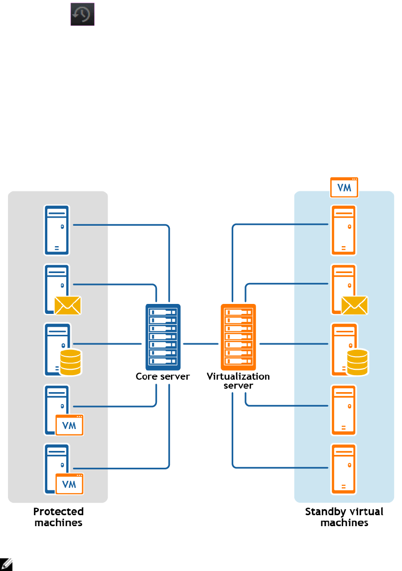
You can perform a virtual export from the Virtual Standby page in the Core Console, or by selecting VM
Export from the Restore drop-down menu on the button bar.
When you perform a virtual export from Rapid Recovery Core, you have two choices:
• You can perform a one-time virtual export, which represents a single snapshot in time from the
information in the recovery point.
• You can create a virtual standby. With virtual standby, the VM snapshot that you create from the
selected recovery point is continually updated by the Core after every scheduled or forced snapshot
captured from the source machine. This creates a high-availability resource for data recovery. If the
protected machine fails, you can boot up the virtual machine to quickly replace it temporarily,
allowing you time to recover the original protected machine without substantial downtime.
The following diagram shows a typical deployment for exporting data to a virtual machine.
Figure 8. Virtual standby deployment
NOTE: In a configuration involving replication, the Core shown represents the target Core.
217

When you export to a virtual machine, the following information is exported:
• All of the backup data from a recovery point
• The operating system and settings from the original protected machine
You can perform virtual export of recovery points for your protected Windows or Linux machines to
VMware, ESXi, Hyper-V, and VirtualBox.
NOTE: For ESXi, VMware Workstation, or Hyper-V, the virtual machine version must be a licensed
version of these virtual machines, not the trial or free versions.
If you have replication set up between two Cores (source and target), you can only export data from the
target Core after the initial replication is complete.
Performing a one-time ESXi export
Complete the steps in this procedure to perform a one-time export to ESXi.
1. In the Rapid Recovery Core Console, in the button bar, click the Restore drop-down menu, and then
click VM Export.
2. In the Virtual Machine Export Wizard, select One-time Export.
3. Click Next.
4. On the Machines page, select the protected machine that you want to export.
5. Click Next.
6. On the Recovery Points page, select the recovery point that you want to use for the export.
7. Click Next.
8. On the Destination page in the Export Wizard, in the Recover to Virtual machine drop-down menu,
select ESX(i).
9. Enter the parameters for accessing the virtual machine as described in the following table, and then
click Next.
Table 103. Virtual machine parameters
Options Description
Host name Enter a name for the host machine.
Port Enter the port for the host machine. The default is 443.
User name Enter the user name for logging on to the host machine.
Password Enter the password for logging on to the host machine.
10. On the Virtual Machine Options page, enter the information described in the following table.
Table 104. Virtual machine options
Option Description
Resource pool Select a resource pool from the drop-down list.
VM
configuration
location
Select a data store from the drop-down list.
Virtual
machine name
Enter a name for the virtual machine.
218

Option Description
Memory Specify the memory usage for the virtual machine by clicking one of the following:
• Use the same amount of RAM as source machine
• Use a specific amount of RAM, and then specify the amount in MB
The minimum amount is 1024 MB and the maximum allowed by the
application is 65536 MB. The maximum amount of memory usage is limited by
the amount of RAM available to the host machine.
Number of
processors
The number of processors (CPUs) you want for the exported virtual machine. The
minimum is 1.
Cores per
processor
The number of cores you want to have for each processor. The minimum is 1.
Disk
provisioning
Select the type of disk provisioning from the following options:
• Thin. Thin provisioning creates a virtual disk the size of the used space on the
original volumes, rather than the entire volume size. For example, if the original
volume is 1 TB, but contains only 2 GB of used space, Rapid Recovery creates a
virtual disk of 2 GB.
• Thick. Thick provisioning creates a new disk or volume that is the same size as
the original volume from the protected server, even if only a portion of the
original volume is being used. For example, if the volume is 1 TB large but
contains only 2 GB of used space, Rapid Recovery creates a virtual disk of 1 TB.
Disk mapping Specify the type of disk mapping from the following options:
• Automatic
• Manual
• With VM
Version Select the version of of ESXi being used to create the virtual machine from the
drop-down list.
11. Click Next.
12. On the Volumes page, select the volumes you want to export, and then click Next.
13. On the Summary page, click Finish to complete the wizard and start the export.
NOTE: You can monitor the status and progress of the export by viewing the Virtual Standby or
Events pages.
Performing a continual (Virtual Standby) ESXi export
Complete the steps in this procedure to perform a continual export to an ESXi virtual machine (VM) using
Rapid Recovery.
1. In the Rapid Recovery Core Console, do one of the following:
• From the Core Console, in the button bar, click the Restore drop-down menu, and then
select VM Export.
1. In the Virtual Machine Export Wizard,
select Continuous (Virtual Standby).
2. Click Next.
• From the Core Console, in the icon bar, click (Virtual Standby).
219

– On the Virtual Standby page, click Add to launch the Virtual Machine Export Wizard.
2. On the Machines page of the Virtual Machine Export Wizard, select the protected machine that you
want to export.
3. Click Next.
4. On the Recovery Points page, select the recovery point that you want to use for the export.
5. Click Next.
6. On the Destination page of the Export Wizard, in the Recover to a Virtual Machine drop-down menu,
select ESXi.
7. Enter the information for accessing the virtual machine as described in the following table, and then
click Next.
Table 105. ESXi credentials
Option Description
Host name Enter a name for the host machine.
Port Enter the port for the host machine. The default is 443.
User name Enter the logon credentials for the host machine.
Password Enter the logon credentials for the host machine.
8. On the Virtual Machine Options page, enter the information described in the following table.
Table 106. Virtual machine options
Option Description
Resource Pool Select a resource pool from the drop-down list.
Data Store Select a data store from the drop-down list.
Virtual
Machine Name
Enter a name for the Virtual Machine.
Memory Specify the memory usage for the virtual machine by clicking one of the following:
• Use the same amount of RAM as source machine
• Use a specific amount of RAM, and then specify the amount in MB
The minimum amount is 1024 MB and the maximum allowed by the
application is 65536 MB. The maximum amount of memory usage is limited by
the amount of RAM available to the host machine.
Number of
processors
The number of processors (CPUs) you want for the exported virtual machine. The
minimum is 1.
Cores per
processor
The number of cores you want to have for each processor. The minimum is 1.
Disk
Provisioning
Select the type of disk provisioning from the following options:
• Thin. Thin provisioning creates a virtual disk the size of the used space on the
original volumes, rather than the entire volume size. For example, if the original
volume is 1 TB, but contains only 2 GB of used space, Rapid Recovery creates a
virtual disk of 2 GB.
• Thick. Thick provisioning creates a new disk or volume that is the same size as
the original volume from the protected server, even if only a portion of the
original volume is being used. For example, if the volume is 1 TB large but
contains 2 GB of used space, Rapid Recovery creates a virtual disk of 1 TB.
220

Option Description
Disk Mapping Specify the type of disk mapping as appropriate (Automatic, Manual, or with VM).
Version Select the version of the virtual machine.
Perform initial
one-time
export
Select to perform the virtual export immediately instead of after the next
scheduled snapshot (optional)
9. Click Next.
10. On the Volumes page, select the volumes you want to export, and then click Next.
11. On the Summary page, click Finish to complete the wizard and start the export.
NOTE: You can monitor the status and progress of the export by viewing the Virtual Standby or
Events pages.
Performing a one-time VMware Workstation export
Complete the steps in this procedure to perform a one-time export to VMware Workstation.
1. In the Rapid Recovery Core Console, in the button bar, click the Restore drop-down menu, click VM
Export.
2. In the Virtual Machine Export Wizard, select One-time Export.
3. Click Next.
4. On the Machines page, select the protected machine that you want to export.
5. Click Next.
6. On the Recovery Points page, select the recovery point that you want to use for the export.
7. Click Next.
8. On the Destination page in the Export Wizard, in the Recover to Virtual machine drop-down menu,
select VMware Workstation, and then click Next.
9. On the Virtual Machine Options page, enter the parameters for accessing the virtual machine as
described in the following table.
Table 107. Virtual machine parameters
Option Description
VM Machine
Location
Specify the path of the local folder or network share on which to create the virtual
machine.
NOTE: If you specified a network share path, you will need to enter a valid
logon credentials for an account that is registered on the target machine. The
account must have read and write permissions to the network share.
User name Enter the logon credentials for the network location for the export.
• If you specified a network share path, you need to enter a valid user name for
an account that is registered on the target machine.
• If you entered a local path, a user name is not required.
Password Enter the logon credentials for the network location for the export.
• If you specified a network share path, you need to enter a valid password for an
account that is registered on the target machine.
• If you entered a local path, a password is not required.
221

Option Description
VM name Enter a name for the virtual machine being created; for example, VM-0A1B2C3D4.
NOTE: The default name is the name of the source machine.
Version Specify the version of VMware Workstation for the virtual machine. You can
choose from:
• VMware Workstation 7.0
• VMware Workstation 8.0
• VMware Workstation 9.0
• VMware Workstation 10.0
• VMware Workstation 11.0
• VMware Workstation 12.0
Amount of
RAM (MB)
Specify the memory usage for the virtual machine by clicking one of the following:
• Use the same amount of RAM as source machine
• Use a specific amount of RAM, and then specify the amount in MB
The minimum amount is 1024 MB and the maximum allowed by the
application is 65536 MB. The maximum amount of memory usage is limited by
the amount of RAM available to the host machine.
Number of
processors
The number of processors (CPUs) you want for the exported virtual machine. The
minimum is 1.
Cores per
processor
The number of cores you want to have for each processor. The minimum is 1.
10. Click Next.
11. On the Volumes page, select the volumes to export, for example, C:\ and D:\, and then click Next.
12. On the Summary page, click Finish to complete the wizard and start the export.
NOTE: You can monitor the status and progress of the export by viewing the Virtual Standby or
Events tab.
Performing a continual (Virtual Standby) VMware Workstation export
Complete the steps in this procedure to perform a continual export to a VMware Workstation virtual
machine (VM) using Rapid Recovery.
1. In the Rapid Recovery Core Console, do one of the following:
• From the Core Console, in the button bar, click the Restore drop-down menu, and then
select VM Export.
1. In the Virtual Machine Export Wizard,
select Continuous (Virtual Standby).
2. Click Next.
• From the Core Console, in the icon bar, click (Virtual Standby).
– On the Virtual Standby page, click Add to launch the Virtual Machine Export Wizard.
2. On the Machines page of the Virtual Machine Export Wizard, select the protected machine that you
want to export.
3. Click Next.
222

4. On the Recovery Points page, select the recovery point that you want to use for the export.
5. Click Next.
6. On the Destination page of the Virtual Machine Export Wizard, in the Recover to a Virtual Machine
drop-down menu, select VMware Workstation, and then click Next.
7. On the Virtual Machine Options page, enter the parameters for accessing the virtual machine as
described in the following table.
Table 108. Virtual machine parameters
Option Description
Target Path Specify the path of the local folder or network share on which to create the virtual
machine.
NOTE: If you specified a network share path, you will need to enter a valid
logon credentials for an account that is registered on the target machine. The
account must have read and write permissions to the network share.
User name Enter the logon credentials for the network location for the export.
• If you specified a network share path, you need to enter a valid user name for
an account that is registered on the target machine.
• If you entered a local path, a user name is not required.
Password Enter the logon credentials for the network location for the export.
• If you specified a network share path, you need to enter a valid password for an
account that is registered on the target machine.
• If you entered a local path, a password is not required.
Virtual
Machine
Enter a name for the virtual machine being created; for example, VM-0A1B2C3D4.
NOTE: The default name is the name of the source machine.
Version Specify the version of VMware Workstation for the virtual machine. You can
choose from:
• VMware Workstation 7.0
• VMware Workstation 8.0
• VMware Workstation 9.0
• VMware Workstation 10.0
• VMware Workstation 11.0
• VMware Workstation 12.0
Memory Specify the memory usage for the virtual machine by clicking one of the following:
• Use the same amount of RAM as source machine
• Use a specific amount of RAM, and then specify the amount in MB
The minimum amount is 1024 MB and the maximum allowed by the
application is 65536 MB. The maximum amount of memory usage is limited by
the amount of RAM available to the host machine.
Number of
processors
The number of processors (CPUs) you want for the exported virtual machine. The
minimum is 1.
223

Option Description
Cores per
processor
The number of cores you want to have for each processor. The minimum is 1.
8. Select Perform initial one-time export to perform the virtual export immediately instead of after the
next scheduled snapshot.
9. Click Next.
10. On the Volumes page, select the volumes to export, for example, C:\ and D:\, and then click Next.
11. On the Summary page, click Finish to complete the wizard and to start the export.
NOTE: You can monitor the status and progress of the export by viewing the Virtual Standby or
Events pages.
Performing a one-time Hyper-V export
Complete the steps in this procedure to perform a one-time export to Hyper-V.
1. In the Rapid Recovery Core Console, in the button bar, click the Restore drop-down menu, click VM
Export.
2. In the Virtual Machine Export Wizard, select One-time Export.
3. Click Next.
4. On the Machines page, select the protected machine that you want to export.
5. Click Next.
6. On the Recovery Points page, select the recovery point that you want to use for the export.
7. Click Next.
8. On the Destination page, in the Export to Virtual machine drop-down menu, select Hyper-V.
9. To export to a local machine with the Hyper-V role assigned, click Use local machine.
10. To indicate that the Hyper-V server is located on a remote machine, click Remote host, and then
enter the information for the remote host as described in the following table.
Table 109. Remote host information
Text Box Description
Host Name Enter an IP address or host name for the Hyper-V server. It represents the IP
address or host name of the remote Hyper-V server.
Port Enter a port number for the machine. It represents the port through which the
Core communicates with this machine.
User name Enter the user name for the user with administrative privileges for the workstation
with the Hyper-V server. It is used to specify the logon credentials for the virtual
machine.
Password Enter the password for the user account with administrative privileges on the
workstation with Hyper-V server. It is used to specify the logon credentials for the
virtual machine.
11. Click Next.
12. On the Virtual Machines Options page, in the VM Machine Location text box, enter the path for the
virtual machine; for example, D:\export. This is used to identify the location of the virtual machine.
224

NOTE: You need to specify the virtual machine location for both local and remote Hyper-V
servers. The path should be a valid local path for the Hyper-V server. Non-existent directories
are automatically created. You should not attempt to create them manually. Export to shared
folders (for example, to \\data\share) is not permitted.
13. In the Virtual Machine Name text box, enter the name for the virtual machine .
The name you enter appears in the list of virtual machines in the Hyper-V Manager console.
14. To specify memory usage, click one of the following:
•Use the same amount of RAM as the source machine. Select this option to identify that the RAM
use is identical between the virtual and source machines.
•Use a specific amount of RAM. Select this option if you want to specify the amount of RAM in
MB.
The minimum amount is 1024 MB, and the maximum allowed by the application is 65536 MB.
The maximum amount of memory usage is limited by the amount of RAM available to the host
machine.
15. To specify the disk format, next to Disk Format, click one of the following:
• VHDX
• VHD
NOTE: Hyper-V Export supports VHDX disk formats if the target machine is running
Windows 8 (Windows Server 2012) or higher. If the VHDX is not supported for your
environment, the option is disabled.
If exporting to Hyper-V generation 2, only VHDX disk format is supported.
16. To specify generation of Hyper-V to use for export, click one of the following:
• Generation 1
• Generation 2
NOTE: Only generation 2 supports the secure boot option.
17. Specify the appropriate network adapter for the exported VM.
18. On the Volumes page, select the volume(s) to export; for example, C:\.
NOTE: If the selected volumes are larger than the appropriate maximum allocations supported
by the application as indicated below, or exceed the amount of space available, you will receive
an error.
• For VHDX disk format, your selected volumes should be no larger than 64 TB.
• For VHD disk format, your selected volumes should be no larger than 2040 GB.
19. On the Volumes page, click Finish to complete the wizard and to start the export.
NOTE: You can monitor the status and progress of the export by viewing the Virtual Standby or
Events pages.
Performing a continual (Virtual Standby) Hyper-V export
Complete the steps in this procedure to perform a continual export to a Hyper-V virtual machine (VM)
using Rapid Recovery.
1. In the Rapid Recovery Core Console, do one of the following:
• From the Core Console, in the button bar, click the Restore drop-down menu, and then
select VM Export.
225

1. In the Virtual Machine Export Wizard,
select Continuous (Virtual Standby).
2. Click Next.
• From the Core Console, in the icon bar, click (Virtual Standby).
– On the Virtual Standby page, click Add to launch the Virtual Machine Export Wizard.
2. On the Machines page of the Virtual Machine Export Wizard, select the protected machine that you
want to export.
3. Click Next.
4. On the Recovery Points page, select the recovery point that you want to use for the export.
5. Click Next.
6. On the Destination page, in the Export to a Virtual Machine drop-down menu, select Hyper-V, and
then do one of the following:
• To export to a local machine with the Hyper-V role assigned, click Use local machine.
• To indicate that the Hyper-V server is located on a remote machine, click Remote host, and then
enter the parameters for the remote host as described in the following table.
Table 110. Remote host information
Text Box Description
Host Name Enter an IP address or host name for the Hyper-V server. It represents the IP
address or host name of the remote Hyper-V server.
Port Enter a port number for the machine. It represents the port through which the
Core communicates with this machine.
User name Enter the user name for the user with administrative privileges for the
workstation with the Hyper-V server. It is used to specify the logon credentials
for the virtual machine.
Password Enter the password for the user account with administrative privileges on the
workstation with Hyper-V server. It is used to specify the logon credentials for
the virtual machine.
7. Click Next.
8. On the Virtual Machines Options page, in the VM Machine Location text box, enter the path for the
virtual machine; for example, D:\export. This is used to identify the location of the virtual machine.
NOTE: You need to specify the virtual machine location for both local and remote Hyper-V
servers. The path should be a valid local path for the Hyper-V server. Non-existent directories
are automatically created. You should not attempt to create them manually. Export to shared
folders (for example, to \\data\share) is not permitted.
9. In the Virtual Machine Name text box, enter the name for the virtual machine.
The name you enter appears in the list of virtual machines in the Hyper-V Manager console.
10. To specify memory usage, click one of the following:
•Use the same amount of RAM as the source machine. Select this option to identify that the RAM
use is identical between the virtual and source machines.
•Use a specific amount of RAM. Select this option if you want to specify the amount of RAM in
MB.
The minimum amount is 1024 MB, and the maximum allowed by the application is 65536 MB.
The maximum amount of memory usage is limited by the amount of RAM available to the host
machine.
11. To specify the disk format, next to Disk Format, click one of the following:
• VHDX
• VHD
226

NOTE: Hyper-V Export supports VHDX disk formats if the target machine is running
Windows 8 (Windows Server 2012) or higher. If the VHDX is not supported for your
environment, the option is disabled.
If exporting to Hyper-V generation 2, only VHDX disk format is supported.
12. To specify generation of Hyper-V to use for export, click one of the following:
• Generation 1
• Generation 2
NOTE: Only generation 2 supports the secure boot option.
13. Specify the appropriate network adapter for the exported VM.
14. On the Volumes page, select the volume(s) to export; for example, C:\.
NOTE: If the selected volumes are larger than the appropriate maximum allocations supported
by the application as indicated below, or exceed the amount of space available, you will receive
an error.
• For VHDX disk format, your selected volumes should be no larger than 64 TB.
• For VHD disk format, your selected volumes should be no larger than 2040 GB.
15. Select Perform initial one-time export to perform the virtual export immediately instead of after the
next scheduled snapshot.
16. On the Volumes page, click Finish to complete the wizard and to start the export.
NOTE: You can monitor the status and progress of the export by viewing the Virtual Standby or
Events pages.
Performing a one-time VirtualBox export
Complete the steps in this procedure to perform a one-time export to VirtualBox.
1. In the Rapid Recovery Core Console, in the button bar, click the Restore drop-down menu, click VM
Export.
2. In the Virtual Machine Export Wizard, select One-time Export.
3. Click Next.
4. On the Machines page, select the protected machine that you want to export.
5. Click Next.
6. On the Recovery Points page, select the recovery point that you want to use for the export.
7. Click Next.
8. On the Destination page in the Export Wizard, in the Recover to Virtual machine drop-down menu,
select VirtualBox, and then click Next.
9. On the Virtual Machine Options page, select Use Windows machine.
10. Enter the parameters for accessing the virtual machine as described in the following table.
Table 111. Virtual machine parameters
Option Description
Virtual
Machine Name
Enter a name for the virtual machine being created.
NOTE: The default name is the name of the source machine.
Target Path Specify a local or remote target path to create the virtual machine.
227

Option Description
NOTE: The target path should not be a root directory.
If you specify a network share path, you will need to enter valid logon
credentials (user name and password) for an account that is registered on the
target machine. The account must have read and write permissions to the
network share.
Memory Specify the memory usage for the virtual machine by clicking one of the following:
• Use the same amount of RAM as source machine
• Use a specific amount of RAM, and then specify the amount in MB
The minimum amount is 1024 MB and the maximum allowed by the
application is 65536 MB. The maximum amount of memory usage is limited by
the amount of RAM available to the host machine.
11. To specify a user account for the virtual machine, select Specify the user account for the exported
virtual machine, and then enter the following information. This refers to a specific user account for
which the virtual machine will be registered in the event there are multiple user accounts on the
virtual machine. When this user account is logged on, only this user will see this Virtual Machine in
VirtualBox manager. If an account is not specified, then the Virtual Machine will be registered for all
existing users on the Windows machine with VirtualBox.
• User name - Enter the user name for which the virtual machine is registered.
• Password - Enter the password for this user account.
12. Click Next.
13. On the Volumes page, select the volumes to export, for example, C:\ and D:\, and then click Next.
14. On the Summary page, click Finish to complete the wizard and to start the export.
NOTE: You can monitor the status and progress of the export by viewing the Virtual Standby or
Events tab.
Performing a continual (Virtual Standby) VirtualBox export
To perform this step, VirtualBox must be installed on the Core machine.
Complete the steps in this procedure to perform a continuous export to a VirtualBox virtual machine (VM)
using Rapid Recovery.
1. In the Rapid Recovery Core Console, do one of the following:
• From the Core Console, in the button bar, click the Restore drop-down menu, and then
select VM Export.
1. In the Virtual Machine Export Wizard,
select Continuous (Virtual Standby).
2. Click Next.
• From the Core Console, in the icon bar, click (Virtual Standby).
– On the Virtual Standby page, click Add to launch the Virtual Machine Export Wizard.
2. On the Machines page of the Virtual Machine Export Wizard, select the protected machine that you
want to export.
3. Click Next.
4. On the Recovery Points page, select the recovery point that you want to use for the export.
228

5. Click Next.
6. On the Destination page of the Export Wizard, in the Recover to a Virtual Machine drop-down
menu, select VirtualBox.
7. On the Virtual Machine Options page, select Remote Linux Machine.
8. Enter information about the virtual machine as described in the following table.
Table 112. Remote Linux machine settings
Option Description
VirtualBox
Host Name
Enter an IP address or host name for the VirtualBox server. This field represents the
IP address or host name of the remote VirtualBox server.
Port Enter a port number for the machine. This number represents the port through
which the Core communicates with this machine.
Virtual
Machine Name
Enter a name for the virtual machine being created.
NOTE: The default name is the name of the source machine.
Target Path Specify a target path to create the virtual machine.
NOTE: It is recommended that you create a root folder from root so that the
virtual machine runs from root. If you do not use root, you will need to create
the destination folder manually on the target machine prior to setting up the
export. You will also need to manually attach or load the virtual machine after
the export.
User Name User name of the account on the target machine, for example, root.
Password Password for the user account on the target machine.
Memory Specify the memory usage for the virtual machine by clicking one of the following:
• Use the same amount of RAM as source machine
• Use a specific amount of RAM, and then specify the amount in MB
The minimum amount is 1024 MB and the maximum allowed by the
application is 65536 MB. The maximum amount of memory usage is limited by
the amount of RAM available to the host machine.
9. Select Perform initial one-time export to perform the virtual export immediately instead of after the
next scheduled snapshot.
10. Click Next.
11. On the Volumes page, select the volumes of data to export, and then click Next.
12. On the Summary page, click Finish to complete the wizard and to start the export.
NOTE: You can monitor the status and progress of the export by viewing the Virtual Standby or
Events pages.
Managing exports
If your Core has virtual export established, the configuration parameters for each virtual export appear as
a row on the Virtual Standby page. From here you can view the status of exports that you currently have
set up, and manage your virtual standby machines. You can add a virtual standby, force export, pause or
resume virtual standby, or remove the requirements for continual export.
229

When a one-time export takes place, the job is listed in the export queue on the Virtual Standby page.
During this time, you can pause, resume, or cancel the export operation.
NOTE: Rapid Recovery supports Hyper-V export to Window 8, Window 8.1, Windows Server 2012
and 2012 R2.
Virtual export to a virtual standby VM does not occur if the VM is powered on.
Complete the steps in this procedure to manage virtual exports.
1. On the Core Console, in the icon bar, click (Virtual Standby).
The Virtual Standby page appears. Here you can view two tables of saved export settings. They
include the information described in the following table.
Table 113. Virtual standby information
Column Description
Select item For each row in the summary table, you can select the check box to perform
actions from the list of menu options preceding the table.
Status
indicator
Colored spheres in the Status column show the status of virtual standby. If you
hover the cursor over the colored circle, the status condition is displayed.
• Green. Virtual standby is successfully configured, is active, and is not paused.
The next export is performed immediately following completion of the next
snapshot.
• Yellow. Virtual standby pauses, but the parameters are still defined and saved in
the Core. However, after a new transfer, the export job will not start
automatically and there will be no new exports for this protected machine until
the status changes.
Machine Name The name of the source machine.
Destination The virtual machine and path to which data is being exported.
Export Type The type of virtual machine platform for the export, such as ESXi, VMware, Hyper-
V, or VirtualBox.
Last Export The date and time of the last export.
If an export has just been added but has not completed, a message displays stating
the export has not yet been performed. If an export has failed or was canceled, a
corresponding message also displays.
Settings The drop-down menu lets you perform the following functions:
•Edit. Lets you edit the virtual standby settings.
•Force. Forces a virtual export.
•Pause. Pauses virtual export. Only available when status is active.
•Resume. Resumes virtual export. Only available when status is paused.
•Remove. Removes the requirement for continual export. Does not remove the
exported VM most recently updated.
230

Table 114. Export queue information
Column Description
Select item For each row in the summary table, you can select the check box to perform
actions from the list of menu options preceding the table.
Destination The virtual machine and path to which data is being exported.
Export Type The type of virtual machine platform for the export, such as ESXi, VMware, Hyper-
V, or VirtualBox.
Schedule Type The type of export as either One-time or Continuous.
Status The progress of the export, displayed as a percentage in a progress bar.
2. To manage saved export settings, select an export, and then click one of the following:
•Edit. Opens the Virtual Machine Export Wizard to the VM Options page. Here you can change
the location of the exported VM, change the version of the VM type, or specify RAM or processors
for the export. To immediately start the VM export, select Perform initial one-time export.
•
•Force. Forces a new export. This option could be helpful when virtual standby is paused and then
resumed, which means the export job will restart only after a new transfer. If you do not want to
wait for the new transfer, you could force an export.
•Pause. Pauses an active export.
•Resume. Resumes the requirement for continue export at the next scheduled or forced snapshot.
3. To remove an export from the system, select the export, and then click Remove.
The export configuration is permanently removed from the system. Removing the virtual standby
configuration does not remove any virtual machine exported as a result of the configuration.
4. To manage the number of exports that run at the same time, do the following:
• Under Export Queue, click Settings.
• In the Maximum Concurrent Exports dialog box, enter the number of exports you want to run
simultaneously. The default number is 5.
• Click Save.
5. To cancel a one-time or continual export currently listed in the Export Queue, select the export, and
then click Cancel.
6. To add a new virtual standby export, you can click Add to launch the Export Wizard. For further
information about setting up virtual standby for a specific virtual machine, see one of the following
topics:
•Exporting data to an ESXi virtual machine
•Exporting data to a VMware Workstation virtual machine
•Exporting data to a Hyper-V virtual machine
•Exporting data to a VirtualBox virtual machine
Exporting data to an ESXi virtual machine
In Rapid Recovery, you can export data to ESXi by performing a one-time export, or by establishing a
continual export (for virtual standby). Complete the steps in the following procedures for the appropriate
type of export.
231

Performing a one-time ESXi export
Complete the steps in this procedure to perform a one-time export to ESXi.
1. In the Rapid Recovery Core Console, in the button bar, click the Restore drop-down menu, and then
click VM Export.
2. In the Virtual Machine Export Wizard, select One-time Export.
3. Click Next.
4. On the Machines page, select the protected machine that you want to export.
5. Click Next.
6. On the Recovery Points page, select the recovery point that you want to use for the export.
7. Click Next.
8. On the Destination page in the Export Wizard, in the Recover to Virtual machine drop-down menu,
select ESX(i).
9. Enter the parameters for accessing the virtual machine as described in the following table, and then
click Next.
Table 115. Virtual machine parameters
Options Description
Host name Enter a name for the host machine.
Port Enter the port for the host machine. The default is 443.
User name Enter the user name for logging on to the host machine.
Password Enter the password for logging on to the host machine.
10. On the Virtual Machine Options page, enter the information described in the following table.
Table 116. Virtual machine options
Option Description
Resource pool Select a resource pool from the drop-down list.
VM
configuration
location
Select a data store from the drop-down list.
Virtual
machine name
Enter a name for the virtual machine.
Memory Specify the memory usage for the virtual machine by clicking one of the following:
• Use the same amount of RAM as source machine
• Use a specific amount of RAM, and then specify the amount in MB
The minimum amount is 1024 MB and the maximum allowed by the
application is 65536 MB. The maximum amount of memory usage is limited by
the amount of RAM available to the host machine.
Number of
processors
The number of processors (CPUs) you want for the exported virtual machine. The
minimum is 1.
Cores per
processor
The number of cores you want to have for each processor. The minimum is 1.
232

Option Description
Disk
provisioning
Select the type of disk provisioning from the following options:
• Thin. Thin provisioning creates a virtual disk the size of the used space on the
original volumes, rather than the entire volume size. For example, if the original
volume is 1 TB, but contains only 2 GB of used space, Rapid Recovery creates a
virtual disk of 2 GB.
• Thick. Thick provisioning creates a new disk or volume that is the same size as
the original volume from the protected server, even if only a portion of the
original volume is being used. For example, if the volume is 1 TB large but
contains only 2 GB of used space, Rapid Recovery creates a virtual disk of 1 TB.
Disk mapping Specify the type of disk mapping from the following options:
• Automatic
• Manual
• With VM
Version Select the version of of ESXi being used to create the virtual machine from the
drop-down list.
11. Click Next.
12. On the Volumes page, select the volumes you want to export, and then click Next.
13. On the Summary page, click Finish to complete the wizard and start the export.
NOTE: You can monitor the status and progress of the export by viewing the Virtual Standby or
Events pages.
Performing a continual (Virtual Standby) ESXi export
Complete the steps in this procedure to perform a continual export to an ESXi virtual machine (VM) using
Rapid Recovery.
1. In the Rapid Recovery Core Console, do one of the following:
• From the Core Console, in the button bar, click the Restore drop-down menu, and then
select VM Export.
1. In the Virtual Machine Export Wizard,
select Continuous (Virtual Standby).
2. Click Next.
• From the Core Console, in the icon bar, click (Virtual Standby).
– On the Virtual Standby page, click Add to launch the Virtual Machine Export Wizard.
2. On the Machines page of the Virtual Machine Export Wizard, select the protected machine that you
want to export.
3. Click Next.
4. On the Recovery Points page, select the recovery point that you want to use for the export.
5. Click Next.
6. On the Destination page of the Export Wizard, in the Recover to a Virtual Machine drop-down menu,
select ESXi.
7. Enter the information for accessing the virtual machine as described in the following table, and then
click Next.
233

Table 117. ESXi credentials
Option Description
Host name Enter a name for the host machine.
Port Enter the port for the host machine. The default is 443.
User name Enter the logon credentials for the host machine.
Password Enter the logon credentials for the host machine.
8. On the Virtual Machine Options page, enter the information described in the following table.
Table 118. Virtual machine options
Option Description
Resource Pool Select a resource pool from the drop-down list.
Data Store Select a data store from the drop-down list.
Virtual
Machine Name
Enter a name for the Virtual Machine.
Memory Specify the memory usage for the virtual machine by clicking one of the following:
• Use the same amount of RAM as source machine
• Use a specific amount of RAM, and then specify the amount in MB
The minimum amount is 1024 MB and the maximum allowed by the
application is 65536 MB. The maximum amount of memory usage is limited by
the amount of RAM available to the host machine.
Number of
processors
The number of processors (CPUs) you want for the exported virtual machine. The
minimum is 1.
Cores per
processor
The number of cores you want to have for each processor. The minimum is 1.
Disk
Provisioning
Select the type of disk provisioning from the following options:
• Thin. Thin provisioning creates a virtual disk the size of the used space on the
original volumes, rather than the entire volume size. For example, if the original
volume is 1 TB, but contains only 2 GB of used space, Rapid Recovery creates a
virtual disk of 2 GB.
• Thick. Thick provisioning creates a new disk or volume that is the same size as
the original volume from the protected server, even if only a portion of the
original volume is being used. For example, if the volume is 1 TB large but
contains 2 GB of used space, Rapid Recovery creates a virtual disk of 1 TB.
Disk Mapping Specify the type of disk mapping as appropriate (Automatic, Manual, or with VM).
Version Select the version of the virtual machine.
Perform initial
one-time
export
Select to perform the virtual export immediately instead of after the next
scheduled snapshot (optional)
9. Click Next.
10. On the Volumes page, select the volumes you want to export, and then click Next.
11. On the Summary page, click Finish to complete the wizard and start the export.
234

NOTE: You can monitor the status and progress of the export by viewing the Virtual Standby or
Events pages.
Exporting data to a VirtualBox virtual machine
In Rapid Recovery, you can export data to VirtualBox Export by performing a one-time export, or by
establishing a continual export (for virtual standby).
NOTE: VirtualBox export of a Windows 10 protected machine is not currently supported.
Complete the steps in the following procedures for the appropriate type of export.
NOTE: To perform this type of export, you should have VirtualBox installed on the Core machine.
Virtual Box Version 4.2.18 or higher is supported for Windows hosts.
Performing a one-time VirtualBox export
Complete the steps in this procedure to perform a one-time export to VirtualBox.
1. In the Rapid Recovery Core Console, in the button bar, click the Restore drop-down menu, click VM
Export.
2. In the Virtual Machine Export Wizard, select One-time Export.
3. Click Next.
4. On the Machines page, select the protected machine that you want to export.
5. Click Next.
6. On the Recovery Points page, select the recovery point that you want to use for the export.
7. Click Next.
8. On the Destination page in the Export Wizard, in the Recover to Virtual machine drop-down menu,
select VirtualBox, and then click Next.
9. On the Virtual Machine Options page, select Use Windows machine.
10. Enter the parameters for accessing the virtual machine as described in the following table.
Table 119. Virtual machine parameters
Option Description
Virtual
Machine Name
Enter a name for the virtual machine being created.
NOTE: The default name is the name of the source machine.
Target Path Specify a local or remote target path to create the virtual machine.
NOTE: The target path should not be a root directory.
If you specify a network share path, you will need to enter valid logon
credentials (user name and password) for an account that is registered on the
target machine. The account must have read and write permissions to the
network share.
Memory Specify the memory usage for the virtual machine by clicking one of the following:
• Use the same amount of RAM as source machine
• Use a specific amount of RAM, and then specify the amount in MB
235
Option Description
The minimum amount is 1024 MB and the maximum allowed by the
application is 65536 MB. The maximum amount of memory usage is limited by
the amount of RAM available to the host machine.
11. To specify a user account for the virtual machine, select Specify the user account for the exported
virtual machine, and then enter the following information. This refers to a specific user account for
which the virtual machine will be registered in the event there are multiple user accounts on the
virtual machine. When this user account is logged on, only this user will see this Virtual Machine in
VirtualBox manager. If an account is not specified, then the Virtual Machine will be registered for all
existing users on the Windows machine with VirtualBox.
• User name - Enter the user name for which the virtual machine is registered.
• Password - Enter the password for this user account.
12. Click Next.
13. On the Volumes page, select the volumes to export, for example, C:\ and D:\, and then click Next.
14. On the Summary page, click Finish to complete the wizard and to start the export.
NOTE: You can monitor the status and progress of the export by viewing the Virtual Standby or
Events tab.
Performing a continual (Virtual Standby) VirtualBox export
To perform this step, VirtualBox must be installed on the Core machine.
Complete the steps in this procedure to perform a continuous export to a VirtualBox virtual machine (VM)
using Rapid Recovery.
1. In the Rapid Recovery Core Console, do one of the following:
• From the Core Console, in the button bar, click the Restore drop-down menu, and then
select VM Export.
1. In the Virtual Machine Export Wizard,
select Continuous (Virtual Standby).
2. Click Next.
• From the Core Console, in the icon bar, click (Virtual Standby).
– On the Virtual Standby page, click Add to launch the Virtual Machine Export Wizard.
2. On the Machines page of the Virtual Machine Export Wizard, select the protected machine that you
want to export.
3. Click Next.
4. On the Recovery Points page, select the recovery point that you want to use for the export.
5. Click Next.
6. On the Destination page of the Export Wizard, in the Recover to a Virtual Machine drop-down
menu, select VirtualBox.
7. On the Virtual Machine Options page, select Remote Linux Machine.
8. Enter information about the virtual machine as described in the following table.
236
Table 120. Remote Linux machine settings
Option Description
VirtualBox
Host Name
Enter an IP address or host name for the VirtualBox server. This field represents the
IP address or host name of the remote VirtualBox server.
Port Enter a port number for the machine. This number represents the port through
which the Core communicates with this machine.
Virtual
Machine Name
Enter a name for the virtual machine being created.
NOTE: The default name is the name of the source machine.
Target Path Specify a target path to create the virtual machine.
NOTE: It is recommended that you create a root folder from root so that the
virtual machine runs from root. If you do not use root, you will need to create
the destination folder manually on the target machine prior to setting up the
export. You will also need to manually attach or load the virtual machine after
the export.
User Name User name of the account on the target machine, for example, root.
Password Password for the user account on the target machine.
Memory Specify the memory usage for the virtual machine by clicking one of the following:
• Use the same amount of RAM as source machine
• Use a specific amount of RAM, and then specify the amount in MB
The minimum amount is 1024 MB and the maximum allowed by the
application is 65536 MB. The maximum amount of memory usage is limited by
the amount of RAM available to the host machine.
9. Select Perform initial one-time export to perform the virtual export immediately instead of after the
next scheduled snapshot.
10. Click Next.
11. On the Volumes page, select the volumes of data to export, and then click Next.
12. On the Summary page, click Finish to complete the wizard and to start the export.
NOTE: You can monitor the status and progress of the export by viewing the Virtual Standby or
Events pages.
Exporting data to a VMware Workstation virtual machine
In Rapid Recovery, you can export data to VMware Workstation by performing a one-time export or by
establishing a continual export (for virtual standby). Complete the steps in the following procedures for
the appropriate type of export.
Performing a one-time VMware Workstation export
Complete the steps in this procedure to perform a one-time export to VMware Workstation.
1. In the Rapid Recovery Core Console, in the button bar, click the Restore drop-down menu, click VM
Export.
2. In the Virtual Machine Export Wizard, select One-time Export.
3. Click Next.
4. On the Machines page, select the protected machine that you want to export.
237

5. Click Next.
6. On the Recovery Points page, select the recovery point that you want to use for the export.
7. Click Next.
8. On the Destination page in the Export Wizard, in the Recover to Virtual machine drop-down menu,
select VMware Workstation, and then click Next.
9. On the Virtual Machine Options page, enter the parameters for accessing the virtual machine as
described in the following table.
Table 121. Virtual machine parameters
Option Description
VM Machine
Location
Specify the path of the local folder or network share on which to create the virtual
machine.
NOTE: If you specified a network share path, you will need to enter a valid
logon credentials for an account that is registered on the target machine. The
account must have read and write permissions to the network share.
User name Enter the logon credentials for the network location for the export.
• If you specified a network share path, you need to enter a valid user name for
an account that is registered on the target machine.
• If you entered a local path, a user name is not required.
Password Enter the logon credentials for the network location for the export.
• If you specified a network share path, you need to enter a valid password for an
account that is registered on the target machine.
• If you entered a local path, a password is not required.
VM name Enter a name for the virtual machine being created; for example, VM-0A1B2C3D4.
NOTE: The default name is the name of the source machine.
Version Specify the version of VMware Workstation for the virtual machine. You can
choose from:
• VMware Workstation 7.0
• VMware Workstation 8.0
• VMware Workstation 9.0
• VMware Workstation 10.0
• VMware Workstation 11.0
• VMware Workstation 12.0
Amount of
RAM (MB)
Specify the memory usage for the virtual machine by clicking one of the following:
• Use the same amount of RAM as source machine
• Use a specific amount of RAM, and then specify the amount in MB
The minimum amount is 1024 MB and the maximum allowed by the
application is 65536 MB. The maximum amount of memory usage is limited by
the amount of RAM available to the host machine.
Number of
processors
The number of processors (CPUs) you want for the exported virtual machine. The
minimum is 1.
238
Option Description
Cores per
processor
The number of cores you want to have for each processor. The minimum is 1.
10. Click Next.
11. On the Volumes page, select the volumes to export, for example, C:\ and D:\, and then click Next.
12. On the Summary page, click Finish to complete the wizard and start the export.
NOTE: You can monitor the status and progress of the export by viewing the Virtual Standby or
Events tab.
Performing a continual (Virtual Standby) VMware Workstation export
Complete the steps in this procedure to perform a continual export to a VMware Workstation virtual
machine (VM) using Rapid Recovery.
1. In the Rapid Recovery Core Console, do one of the following:
• From the Core Console, in the button bar, click the Restore drop-down menu, and then
select VM Export.
1. In the Virtual Machine Export Wizard,
select Continuous (Virtual Standby).
2. Click Next.
• From the Core Console, in the icon bar, click (Virtual Standby).
– On the Virtual Standby page, click Add to launch the Virtual Machine Export Wizard.
2. On the Machines page of the Virtual Machine Export Wizard, select the protected machine that you
want to export.
3. Click Next.
4. On the Recovery Points page, select the recovery point that you want to use for the export.
5. Click Next.
6. On the Destination page of the Virtual Machine Export Wizard, in the Recover to a Virtual Machine
drop-down menu, select VMware Workstation, and then click Next.
7. On the Virtual Machine Options page, enter the parameters for accessing the virtual machine as
described in the following table.
Table 122. Virtual machine parameters
Option Description
Target Path Specify the path of the local folder or network share on which to create the virtual
machine.
NOTE: If you specified a network share path, you will need to enter a valid
logon credentials for an account that is registered on the target machine. The
account must have read and write permissions to the network share.
User name Enter the logon credentials for the network location for the export.
• If you specified a network share path, you need to enter a valid user name for
an account that is registered on the target machine.
• If you entered a local path, a user name is not required.
239

Option Description
Password Enter the logon credentials for the network location for the export.
• If you specified a network share path, you need to enter a valid password for an
account that is registered on the target machine.
• If you entered a local path, a password is not required.
Virtual
Machine
Enter a name for the virtual machine being created; for example, VM-0A1B2C3D4.
NOTE: The default name is the name of the source machine.
Version Specify the version of VMware Workstation for the virtual machine. You can
choose from:
• VMware Workstation 7.0
• VMware Workstation 8.0
• VMware Workstation 9.0
• VMware Workstation 10.0
• VMware Workstation 11.0
• VMware Workstation 12.0
Memory Specify the memory usage for the virtual machine by clicking one of the following:
• Use the same amount of RAM as source machine
• Use a specific amount of RAM, and then specify the amount in MB
The minimum amount is 1024 MB and the maximum allowed by the
application is 65536 MB. The maximum amount of memory usage is limited by
the amount of RAM available to the host machine.
Number of
processors
The number of processors (CPUs) you want for the exported virtual machine. The
minimum is 1.
Cores per
processor
The number of cores you want to have for each processor. The minimum is 1.
8. Select Perform initial one-time export to perform the virtual export immediately instead of after the
next scheduled snapshot.
9. Click Next.
10. On the Volumes page, select the volumes to export, for example, C:\ and D:\, and then click Next.
11. On the Summary page, click Finish to complete the wizard and to start the export.
NOTE: You can monitor the status and progress of the export by viewing the Virtual Standby or
Events pages.
Exporting data to a Hyper-V virtual machine
In Rapid Recovery, you can export data to Hyper-V Export by performing a one-time export, or by
establishing a continual export (for Virtual Standby).
Rapid Recovery supports first-generation Hyper-V export to the following hosts:
• Windows 8
• Windows 8.1
• Windows Server 2008
• Windows Server 2008 R2
240

• Windows Server 2012
• Windows Server 2012 R2
Rapid Recovery supports second-generation Hyper-V export to the following hosts:
• Windows 8.1
• Windows Server 2012 R2
NOTE: Not all protected machines can be exported to Hyper-V second generation hosts.
Only protected machines with the following Unified Extensible Firmware Interface (UEFI) operating
systems support virtual export to Hyper-V second generation hosts:
• Windows 8 (UEFI)
• Windows 8.1 (UEFI)
• Windows Server 2012 (UEFI)
• Windows Server 2012 R2 (UEFI)
NOTE: Hyper-V export to second-generation VM can fail if the Hyper-V host does not have
enough RAM allocated to perform the export.
Complete the steps in the following procedures for the appropriate type of export.
Performing a one-time Hyper-V export
Complete the steps in this procedure to perform a one-time export to Hyper-V.
1. In the Rapid Recovery Core Console, in the button bar, click the Restore drop-down menu, click VM
Export.
2. In the Virtual Machine Export Wizard, select One-time Export.
3. Click Next.
4. On the Machines page, select the protected machine that you want to export.
5. Click Next.
6. On the Recovery Points page, select the recovery point that you want to use for the export.
7. Click Next.
8. On the Destination page, in the Export to Virtual machine drop-down menu, select Hyper-V.
9. To export to a local machine with the Hyper-V role assigned, click Use local machine.
10. To indicate that the Hyper-V server is located on a remote machine, click Remote host, and then
enter the information for the remote host as described in the following table.
Table 123. Remote host information
Text Box Description
Host Name Enter an IP address or host name for the Hyper-V server. It represents the IP
address or host name of the remote Hyper-V server.
Port Enter a port number for the machine. It represents the port through which the
Core communicates with this machine.
User name Enter the user name for the user with administrative privileges for the workstation
with the Hyper-V server. It is used to specify the logon credentials for the virtual
machine.
241

Text Box Description
Password Enter the password for the user account with administrative privileges on the
workstation with Hyper-V server. It is used to specify the logon credentials for the
virtual machine.
11. Click Next.
12. On the Virtual Machines Options page, in the VM Machine Location text box, enter the path for the
virtual machine; for example, D:\export. This is used to identify the location of the virtual machine.
NOTE: You need to specify the virtual machine location for both local and remote Hyper-V
servers. The path should be a valid local path for the Hyper-V server. Non-existent directories
are automatically created. You should not attempt to create them manually. Export to shared
folders (for example, to \\data\share) is not permitted.
13. In the Virtual Machine Name text box, enter the name for the virtual machine .
The name you enter appears in the list of virtual machines in the Hyper-V Manager console.
14. To specify memory usage, click one of the following:
•Use the same amount of RAM as the source machine. Select this option to identify that the RAM
use is identical between the virtual and source machines.
•Use a specific amount of RAM. Select this option if you want to specify the amount of RAM in
MB.
The minimum amount is 1024 MB, and the maximum allowed by the application is 65536 MB.
The maximum amount of memory usage is limited by the amount of RAM available to the host
machine.
15. To specify the disk format, next to Disk Format, click one of the following:
• VHDX
• VHD
NOTE: Hyper-V Export supports VHDX disk formats if the target machine is running
Windows 8 (Windows Server 2012) or higher. If the VHDX is not supported for your
environment, the option is disabled.
If exporting to Hyper-V generation 2, only VHDX disk format is supported.
16. To specify generation of Hyper-V to use for export, click one of the following:
• Generation 1
• Generation 2
NOTE: Only generation 2 supports the secure boot option.
17. Specify the appropriate network adapter for the exported VM.
18. On the Volumes page, select the volume(s) to export; for example, C:\.
NOTE: If the selected volumes are larger than the appropriate maximum allocations supported
by the application as indicated below, or exceed the amount of space available, you will receive
an error.
• For VHDX disk format, your selected volumes should be no larger than 64 TB.
• For VHD disk format, your selected volumes should be no larger than 2040 GB.
19. On the Volumes page, click Finish to complete the wizard and to start the export.
NOTE: You can monitor the status and progress of the export by viewing the Virtual Standby or
Events pages.
242

Performing a continual (Virtual Standby) Hyper-V export
Complete the steps in this procedure to perform a continual export to a Hyper-V virtual machine (VM)
using Rapid Recovery.
1. In the Rapid Recovery Core Console, do one of the following:
• From the Core Console, in the button bar, click the Restore drop-down menu, and then
select VM Export.
1. In the Virtual Machine Export Wizard,
select Continuous (Virtual Standby).
2. Click Next.
• From the Core Console, in the icon bar, click (Virtual Standby).
– On the Virtual Standby page, click Add to launch the Virtual Machine Export Wizard.
2. On the Machines page of the Virtual Machine Export Wizard, select the protected machine that you
want to export.
3. Click Next.
4. On the Recovery Points page, select the recovery point that you want to use for the export.
5. Click Next.
6. On the Destination page, in the Export to a Virtual Machine drop-down menu, select Hyper-V, and
then do one of the following:
• To export to a local machine with the Hyper-V role assigned, click Use local machine.
• To indicate that the Hyper-V server is located on a remote machine, click Remote host, and then
enter the parameters for the remote host as described in the following table.
Table 124. Remote host information
Text Box Description
Host Name Enter an IP address or host name for the Hyper-V server. It represents the IP
address or host name of the remote Hyper-V server.
Port Enter a port number for the machine. It represents the port through which the
Core communicates with this machine.
User name Enter the user name for the user with administrative privileges for the
workstation with the Hyper-V server. It is used to specify the logon credentials
for the virtual machine.
Password Enter the password for the user account with administrative privileges on the
workstation with Hyper-V server. It is used to specify the logon credentials for
the virtual machine.
7. Click Next.
8. On the Virtual Machines Options page, in the VM Machine Location text box, enter the path for the
virtual machine; for example, D:\export. This is used to identify the location of the virtual machine.
NOTE: You need to specify the virtual machine location for both local and remote Hyper-V
servers. The path should be a valid local path for the Hyper-V server. Non-existent directories
are automatically created. You should not attempt to create them manually. Export to shared
folders (for example, to \\data\share) is not permitted.
9. In the Virtual Machine Name text box, enter the name for the virtual machine.
The name you enter appears in the list of virtual machines in the Hyper-V Manager console.
10. To specify memory usage, click one of the following:
243

•Use the same amount of RAM as the source machine. Select this option to identify that the RAM
use is identical between the virtual and source machines.
•Use a specific amount of RAM. Select this option if you want to specify the amount of RAM in
MB.
The minimum amount is 1024 MB, and the maximum allowed by the application is 65536 MB.
The maximum amount of memory usage is limited by the amount of RAM available to the host
machine.
11. To specify the disk format, next to Disk Format, click one of the following:
• VHDX
• VHD
NOTE: Hyper-V Export supports VHDX disk formats if the target machine is running
Windows 8 (Windows Server 2012) or higher. If the VHDX is not supported for your
environment, the option is disabled.
If exporting to Hyper-V generation 2, only VHDX disk format is supported.
12. To specify generation of Hyper-V to use for export, click one of the following:
• Generation 1
• Generation 2
NOTE: Only generation 2 supports the secure boot option.
13. Specify the appropriate network adapter for the exported VM.
14. On the Volumes page, select the volume(s) to export; for example, C:\.
NOTE: If the selected volumes are larger than the appropriate maximum allocations supported
by the application as indicated below, or exceed the amount of space available, you will receive
an error.
• For VHDX disk format, your selected volumes should be no larger than 64 TB.
• For VHD disk format, your selected volumes should be no larger than 2040 GB.
15. Select Perform initial one-time export to perform the virtual export immediately instead of after the
next scheduled snapshot.
16. On the Volumes page, click Finish to complete the wizard and to start the export.
NOTE: You can monitor the status and progress of the export by viewing the Virtual Standby or
Events pages.
Managing aging data
This section describes how to manage aging snapshot data saved to your repository. It includes
information about retaining recovery points in your repository, retention policies, and the resulting
process of rolling up recovery points to conserve space. It describes the new ability to relocate recovery
points from your repository to a Dell DR backup and deduplication appliance.
This section also describes how to archive data for long-term storage that is not subject to rollup, and
how to access recovery points that have been archived.
About Rapid Recovery data retention and archiving
Each time your Core captures a snapshot, the data is saved as a recovery point to your repository.
Recovery points naturally accumulate over time. The Core uses a retention policy to determine how long
snapshot data is retained in the repository. During the rollup portion of the nightly job, the Core enforces
244

the retention policy to reduce the amount of storage space consumed. During rollup, the date of each
recovery point is compared to the date of the most recent recovery point. The Core then combines or
"rolls up" older recovery points. Over time, older recovery points are eventually replaced with newer ones
as the oldest recovery points "age out" beyond the oldest retention period.
To keep recovery points that would otherwise be combined and eventually deleted, you can create an
archive from the Core Console. An archive is a file containing the full set of recovery points for machines
protected on your Core at the point in time in which it was created.
You can store an archive in a file system, or on a storage account in the cloud.
If you need to access the data in a recovery point, you can later attach (for Rapid Recovery 6.x and later)
or import the archive, restoring those recovery points to your repository. You can then take the same
actions on that data as with any other recovery points currently in your Core.
NOTE: Since the Core recognizes the original dates of recovery points in an archive, imported
recovery points may again be rolled up or deleted during the next nightly job period. If you want to
retain older recovery points, you can disable rollup for the relevant machines, or you can extend the
retention period.
Managing retention policies
A retention policy is a set of rules that dictates the length of time for the Core to retain recovery points
before starting to roll them up. Retention policies can be set to roll up based on hours, days, weeks,
months and years. You can set up to six rules (the default policy sets five rules).
Since you can back up as frequently as every 5 minutes, the first rule in the retention policy typically sets
how long to retain all recovery points. For example, if you back up a machine every quarter hour, 96
recovery points are saved to the repository for that machine per day, until rollup begins. Without
managing your retention policy, that amount of data can quickly fill a repository.
NOTE: Administrators should note that frequent backups can have an impact on network traffic.
Other factors affecting network traffic include other transfers (such as replication), the change rate
of your data, and your network hardware, cables and switches.
The Core comes preset with a default retention policy. The default policy works retains:
• All recovery points for three days
• One recovery point per hour for two days
• One recovery point per day for four days
• One recovery point per week for three weeks
• One recovery point per month for two months
• One recovery point per year for X years (disabled in default policy).
Following this default policy, the oldest recovery point is typically 92 days old. Data past that origination
date for a default policy is deleted.
Setting the retention policy at the Core level applies automatically to all machines that the Core protects.
You can change the default policy to suit your needs.
For any machine, you can also create a custom retention policy. Setting the policy at the machine level
lets you specify a different retention policy than the default Core policy. For more information about
245

configuring retention policies, see Configuring Core default retention policy settings and Customizing
retention policy settings for a protected machine.
Configuring Core default retention policy settings
The retention policy for the Core specifies how long the recovery points for a protected machine are
stored in the repository.
The Core retention policy is enforced by a rollup process which is performed as one component of
running nightly jobs. Then, recovery points beyond the age specified in the retention policy are “rolled
up” (combined) into fewer recovery points that cover a less granular period of time. Applying the
retention policy on a nightly basis results in the ongoing rollup of aging backups. This eventually results in
the deletion of the oldest recovery points, based on the requirements specified in that retention policy.
Different retention settings can be configured for source and target Cores.
NOTE: This topic is specific to customizing retention policy settings on the Rapid Recovery Core.
When you save customized retention policy settings on the Core, you establish the default retention
policy settings which can be applied to all machines protected by this Core. For more information
on customizing retention policy settings for individual protected machines, see Customizing
retention policy settings for a protected machine.
1. Navigate to the Rapid Recovery Core Console.
2. On the icon bar, click (Settings), and then do one of the following:
• From the list of Core settings on the left side of the Settings page, click Nightly Jobs.
• Scroll down on the right side of the Settings page until you can see the Nightly Jobs heading.
The Nightly Jobs core settings appear.
3. Under Nightly Jobs, click Change.
The Nightly Jobs dialog box appears.
4. To specify the time intervals for retaining the backup data as needed, in the Nightly Jobs pane, select
Rollup, and then click Settings.
The Configuration dialog box for the Core default retention policy appears.
5. To restore Core retention policy settings to the default values at any time, at the bottom of the
Configuration dialog box, click Restore Defaults and then click Yes to confirm.
All settings are restored to the default values described in the table in Step 6.
6. To define a retention policy, first specify the primary setting that determines how long initial backup
snapshots are retained. Then proceed to define a cascading set of rollup requirements that
determines the intervals between when recovery points should be rolled up.
The retention policy options are described in the following table.
Table 125. Schedule options for default retention policy
Text Box Description
Keep all recovery
points for n [retention
time period]
Specifies the retention period for the recovery points.
Enter a number to represent the retention period and then select the time
period. The default is 3 days.
246

Text Box Description
You can choose from: Days, Weeks, Months, or Years
…and then keep one
recovery point per hour
for n [retention time
period]
Provides a more granular level of retention. It is used as a building block
with the primary setting to further define how long recovery points are
maintained.
Enter a number to represent the retention period and then select the time
period. The default is 2 days.
You can choose from: Days, Weeks, Months, or Years
…and then keep one
recovery point per day
for n [retention time
period]
Provides a more granular level of retention. It is used as a building block to
further define how long recovery points are maintained.
Enter a number to represent the retention period and then select the time
period. The default is 4 days.
You can choose from: Days, Weeks, Months, or Years
…and then keep one
recovery point per
week for n [retention
time period]
Provides a more granular level of retention. It is used as a building block to
further define how long recovery points are maintained.
Enter a number to represent the retention period and then select the time
period. The default is 3 weeks.
You can choose from: Weeks, Months, or Years
…and then keep one
recovery point per
month for n [retention
time period]
Provides a more granular level of retention. It is used as a building block to
further define how long recovery points are maintained.
Enter a number to represent the retention period and then select the time
period. The default is 2 months.
You can choose from: Months or Years
…and then keep one
recovery point per year
for n [retention time
period]
Enter a number to represent the retention period and then select the time
period.
You can choose from: Years
The oldest recovery point is determined by the retention policy settings.
The following is an example of how the retention period is calculated.
Keep all recovery points for three days.
…and then keep one recovery point per hour for three days
…and then keep one recovery point per day for four days
…and then keep one recovery point per week for three weeks
…and then keep one recovery point per month for two months
…and then keep one recovery point per month for one year
247

In this example, the oldest recovery point would be one year, 4 months, and 6 days old.
7. When satisfied with your retention policy settings, click Save.
The Configuration dialog box closes.
8. In the Nightly Jobs dialog box, click OK.
The Nightly Jobs dialog box closes. The retention policy you defined is applied during the nightly
rollup.
You can also to apply these settings when specifying the retention policy for any individual protected
machine. For more information about setting retention policies for a protected machine, see
Customizing retention policy settings for a protected machine.
Customizing retention policy settings for a protected machine
The retention policy for a protected machine specifies how long recovery points are stored in the
repository. Typically, each protected machine uses the default retention policy established for the Core
unless you specify a custom retention policy, as described in this procedure.
Use this procedure to define a custom retention policy for a protected machine, including a replicated
machine.
1. From the Protected Machines menu of the Rapid Recovery Core Console, click the name of the
machine that you want to modify.
The Summary page for the selection machine appears.
2. Click the Settings menu.
The Settings page appears, showing configuration settings for the selected machine.
3. Optionally, click the Nightly Jobs link to scroll down in the Settings page to view nightly jobs
settings.
4. Under the Nightly Jobs heading, click Change.
The Nightly Jobs dialog box appears.
5. To specify the time intervals for retaining the backup data as needed, select Rollup and then click
Settings.
The Configuration dialog box for the retention policy appears.
6. If customizing retention policies settings for a replicated machine, and if you see a caution notifying
you to perform an Integrity Check on your repository, proceed with this step. Otherwise, skip to the
next step.
a. If you are prepared to perform the job, click Check Integrity
b. Click Yes to confirm the Integrity Check job.
NOTE: Running this job could take a substantial amount of time, based on the size of your
repository. During this time, you can perform no other actions (snapshots, replication, virtual
export, and so on) in the repository. For information about this job, see About checking the
integrity of DVM repositories.
• Once the Check Integrity job completes all child job successfully, return to this procedure and
continue with the next step.
7. In the Configuration dialog box, do one of the following:
• To use the default retention policy for this protected machine, select Use Core default retention
policy, and then click Save. The default policy is applied to this agent.
• To define a custom retention policy for this agent, select Use custom retention policy, and then
continue with the next step.
248

The Configuration dialog box expands to show custom retention policy information.
8. Enter the custom schedule for retaining the recovery points as described in the following table.
Table 126. Schedule options for custom retention policy
Text Box Description
Keep all recovery
points for n [retention
time period]
Specifies the retention period for the recovery points.
Enter a number to represent the retention period and then select the time
period. The default is 3 days.
You can choose from: Days, Weeks, Months, and Years
…and then keep one
recovery point per hour
for n [retention time
period]
Provides a more granular level of retention. It is used as a building block
with the primary setting to further define how long recovery points are
maintained.
Enter a number to represent the retention period and then select the time
period. The default is 2 days.
You can choose from: Days, Weeks, Months, and Years
…and then keep one
recovery point per day
for n [retention time
period]
Provides a more granular level of retention. It is used as a building block to
further define how long recovery points are maintained.
Enter a number to represent the retention period and then select the time
period. The default is 4 days.
You can choose from: Days, Weeks, Months, and Years
…and then keep one
recovery point per
week for n [retention
time period]
Provides a more granular level of retention. It is used as a building block to
further define how long recovery points are maintained.
Enter a number to represent the retention period and then select the time
period. The default is 3 weeks.
You can choose from: Weeks, Months, and Years
…and then keep one
recovery point per
month for n [retention
time period]
Provides a more granular level of retention. It is used as a building block to
further define how long recovery points are maintained.
Enter a number to represent the retention period and then select the time
period. The default is 2 months.
You can choose from: Months and Years
…and then keep one
recovery point per year
for n [retention time
period]
Enter a number to represent the retention period and then select the time
period.
You can choose from: Years
The following is an example of how the retention period is calculated.
Keep all recovery points for three days.
…and then keep one recovery point per hour for three days
…and then keep one recovery point per day for four days
249

…and then keep one recovery point per week for three weeks
…and then keep one recovery point per month for two months
…and then keep one recovery point per month for one year
In this example, the oldest recovery point would be one year, 3 months old.
9. If you want to retain all recovery points in your primary repository, clear the Relocate outdated
recovery points to an R3 repository option and skip the next step.
10. If you want to relocate recovery points from your primary repository to an R3 repository stored on a
Dell DR series backup appliance, do the following:.
a. Select the Relocate outdated recovery points to an R3 repository option.
b. Specify the age at which you want to relocate recovery points from your primary repository to
the R3 repository.
You can specify the age by weeks, months or years. The shortest period you can set is 1 week.
c. From the Select a repository drop-down menu, select the R3 repository to which you want to
tier the specified recovery points.
NOTE: Regardless of where recovery points are located (local DVM repository or in a remote R3
repository on a DR backup appliance), they are still subject to the retention policy, and will still
be rolled up. If you need to retain older recovery points, one method is to archive. The other
approach is to disable rollup or extend the retention period for the relevant protected
machines.
11. Click Save.
Forcing rollup for a protected machine
You can bypass your scheduled retention policy by forcing recovery points to roll up at the protected
machine level.
1. From the Protected Machines menu of the Rapid Recovery Core Console, click the name of a
specific protected machine.
The Summary page for the selection machine appears.
2. Click the More drop-down menu at the top of the protected machine view, and then select
Retention Policy.
The Retention Policy page for the specified machine appears.
3. Click Force Rollup.
4. In the dialog box, click Yes to confirm.
Rapid Recovery initiates rollup for this machine, regardless of the retention policy schedule.
Replication
This section describes how to configure and manage the replication of protected data from a Rapid
Recovery source Core to a Rapid Recovery target Core for disaster recovery.
Replication with Rapid Recovery
This section provides conceptual and procedural information to help you understand and configure
replication in Rapid Recovery.
250

Replication is the process of copying recovery points from one Rapid Recovery Core and transmitting
them to another Rapid Recovery Core for disaster recovery purposes. The process requires a paired
source-target relationship between two or more Cores.
The source Core copies the recovery points of selected protected machines, and then asynchronously
and continually transmits that snapshot data to the target Core.
Unless you change the default behavior by setting a replication schedule, the Core starts a replication job
immediately after completion of every backup snapshot, checksum check, attachability check, and the
nightly jobs. For more information, see Scheduling replication.
For optimum data security, administrators usually use a target Core at a remote disaster recovery site.
You can configure outbound replication to a company-owned data center or remote disaster recovery
site (that is, a “self-managed” target Core). Or, you can configure outbound replication to a third-party
managed service provider (MSP) or cloud provider that hosts off-site backup and disaster recovery
services. When replicating to a third-party target Core, you can use built-in work flows that let you
request connections and receive automatic feedback notifications.
Replication is managed on a per-protected-machine basis. Any machine (or all machines) protected or
replicated on a source Core can be configured to replicate to a target Core.
Possible scenarios for replication include:
•Replication to a local location. The target Core is located in a local data center or on-site location,
and replication is maintained at all times. In this configuration, the loss of the Core would not prevent
a recovery.
•Replication to an off-site location. The target Core is located at an off-site disaster recovery facility
for recovery in the event of a loss.
•Mutual replication. Two data centers in two different locations each contain a Core and are
protecting machines and serving as the off-site disaster recovery backup for each other. In this
scenario, each Core replicates the protected machines to the Core that is located in the other data
center.
•Hosted and cloud replication. Rapid Recovery MSP partners maintain multiple target Cores in a data
center or a public cloud. On each of these Cores, the MSP partner lets one or more of their customers
replicate recovery points from a source Core on the customer’s site to the MSP’s target Core for a fee.
NOTE: In this scenario, customers only have access to their own data.
Possible replication configurations include:
•Point-to-point replication. Replicates one or more protected machines from a single source Core to
a single target Core.
251
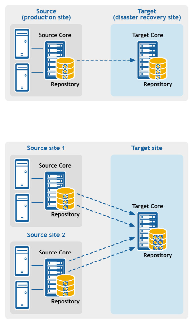
Figure 9. Point-to-point replication configuration
•Multipoint-to-point replication. Replicates protected machines from multiple source Cores to a
single target Core.
Figure 10. Multipoint-to-point replication configuration
•Point-to-multipoint replication. Replicates one or more protected machines from a single source
Core to more than one target Core.
252

Figure 11. Point-to-multipoint replication configuration
•Multi-hop replication. Replicates one or more protected machines from one target Core to another
target Core, producing additional failover or recovery options on the replicated Core.
253

Figure 12. Multi-hop replication configuration
If using Dell Data Protection backup appliances such as the DL1x00 or DL4x00 series, the target Core to
which you replicate must have a valid software license configured. These hardware appliances include a
replication target license with purchase. Check for your license key in the welcome email message you
received when purchased the appliance. For assistance, visit the Licensing Assistance website at https://
support.software.dell.com/licensing-assistance or email license@software.dell.com.
Recovery point chains and orphans
Rapid Recovery captures snapshots of a protected machine, and saves the data to a repository as a
recovery point. The first recovery point saved to the Core is called a base image. The base image includes
the operating system, applications, and settings for each volume you choose to protect, as well as all data
on those volumes. Successive backups are incremental snapshots, which consist only of data changed on
the protected volumes since the last backup. The base image plus all incremental snapshots together
form a complete recovery point chain.
From a complete recovery point chain, you can restore data with ease and confidence, using the full
range of recovery options available to Rapid Recovery. These options include file-level restore, volume-
level restore, and bare metal restore.
Since logically you cannot restore from data that does not exist, in the case of an incomplete recovery
point chain, you cannot restore data at the volume level or perform a bare metal restore. In such cases,
you can still restore any data that does exist in a recovery point at the file level.
254

If the information you want to restore from a recovery point is in a previous backup that is not available to
the Core (an earlier incremental snapshot or the base image), the recovery point is said to be orphaned.
Orphaned recovery points are typical in some replication scenarios.
For example, when you first establish replication, your options for restoring data from the replicated
recovery points are limited. Until all backup data from the source Core is transmitted to the target Core,
creating full recovery point chains from the orphans, you can only perform file-level restore.
When replication begins
By default, replication transfer jobs are automatically queued by the Core immediately after each
regularly scheduled backup transfer completes. Thus, unless the replication schedule for a protected
machine is customized, its replication schedule is based on its standard backup snapshot schedule.
When you first set up replication, if one or more recovery points exist on the source Core, the replication
process begins immediately, unless:
• You select the option to initially pause replication, or
• You select the option to use a seed drive to perform the initial transfer.
If you pause replication initially, replication begins when you explicitly resume replication.
If you set up replication and specify the use of a seed drive, replication to the target Core begins with the
next regularly scheduled backup snapshot.
NOTE: You can also force a backup of the protected machine after establishing replication. This
causes replication to begin immediately after the protected machine snapshot completes.
If you specify a seed drive when you set up replication, only future backup transfers are replicated. If you
want existing recovery points from the original protected machine to exist on the target Core, you must
seed data from the protected machine. To seed data, create a seed drive from the source Core, and then
consume the seed drive on the target Core.
You can also customize the replication schedule for a protected machine. For example, if you use the
default protection schedule of one backup per hour, you can specify that the source Core replicate to the
target Core at a different schedule (for example, once daily at 2AM).
Determining your seeding needs and strategy
The following topics discuss restoring from replicated data and whether you need to seed recovery point
data from the source Core.
When seeding data is required
When you first establish replication, unless you specify the use a seed drive, the source Core begins
transmitting all of the recovery points for the selected machines to the target Core. Transmitting your
data over the network can take a good deal of time. Factors involved include the speed of your network,
the robustness of your network architecture, and the amount of data to be transmitted to the target
Core. For example, if the backup data on the source Core measures 10GB and the WAN link transfers
24Mbps, the transfer could take approximately one hour to complete.
Based on the amount of information you want to copy to the target Core, the seed drive can add up to
hundreds or thousands of gigabytes of data. Many organizations choose not to consume the network
255

bandwidth required, and instead opt to define and consume a seed drive. For more information, see
Performance considerations for replicated data transfer.
If you specify the use of a seed drive when defining replication, then only recovery points saved to the
source Core after you establish replication are replicated to the target Core. Backups saved on the source
Core before replication was established will not be present on the target Core until you explicitly seed the
data, using the following process.
To avoid slowing down your network with an intensive transfer of historical data, seed your prior backup
data to the target Core using a seed drive. A seed drive is an archive file that copies a set of deduplicated
base images and incremental snapshots from the source Core. The seed drive file contains the full set of
previous recovery points for the protected machines you want to replicate from the source Core to the
target Core.
Move the seed drive file to a storage volume which you then make available to the target Core. Then you
consume the information from the seed drive. This involves attaching the volume with the seed drive
image to the target Core and importing the data to the repository from the Core Console. This process
repairs orphans, uniting incremental snapshots replicated to the target Core with their base images, to
form one or more complete recovery point chains. This process is sometimes called copy-consume.
Seeding data from your source Core is not always required. For example:
• If you are setting up replication for a new Rapid Recovery Core, seeding is not required.
• If the data from previous snapshots are not critical for your replicated data, and you only need to
recover data saved after replication is set up, seeding is not required.
NOTE: In this case, Dell recommends capturing a new base image immediately before or
immediately after setting up replication. This step ensures a full recovery point chain exists on
the target Core from which to restore data in the future.
• If you captured a base image immediately before setting up replication, and only have a need to
restore from data captured after that date, seeding is not required.
• If you set up replication without specifying a seed drive, then the snapshot data transmits over the
network from the source Core to the target Core.
If one of these situations applies to you, you do not need to seed data. In such cases, replication can be
completed entirely from the source Core.
If you set up replication for a Core with existing recovery points and may need to restore at the volume
level, want to perform a BMR, or want to restore data from an earlier base image or incremental
snapshot, seeding is required. In these situations, consider your seeding needs and strategy. Review the
information in this topic and decide whether you will seed to your target Core, and which approach you
will use.
Approaches to seeding data
If you want your replicated machines on a target Core to have access to data saved previously on the
original source Core, seed your target Core using one of the following approaches:
1. Seed to the target Core over a network connection. Specify the use of a seed drive when you
define replication. you can then share the folder containing the seed drive with the target Core, and
consume the seed drive file over the network. For large data or slow connections, seeding by this
method can take a substantial amount of time and consume substantial network bandwidth.
NOTE: Dell does not recommend seeding large amounts of data over a network connection.
Initial seeding potentially involves very large amounts of data, which could overwhelm a typical
WAN connection.
256

2. Transfer backup data from the source Core using physical storage media. Transfer the seed drive
file to a portable external removable storage device. This approach is typically useful for large sets of
data or sites with slow network connections. Seeding using this method requires you to perform the
following steps:
a. Create a seed archive from the source Core, saving it to removable media.
b. Transport the seed drive to the physical location of the target Core.
c. Attach the drive to the target Core.
d. Consume the data from the seed drive to the repository of the target Core.
If replicating to a third-party Core, once your media is received by the MSP, a data center
representative typically attaches the media and notifies you when it is ready for you to consume (or
import) the seed data into the Core.
NOTE: Because large amounts of data need to be copied to the storage device, an eSATA, USB
3.0, or other high-speed connection is recommended. If the total size of the seed data archive
is larger than the space available on the removable media, the archive can span across multiple
devices.
3. For source and target Cores stored on virtual hosts, transfer backup data using a virtual hard disk.
If your source Core and target Core are both on a virtual host, you can define and consume a seed
drive on virtual storage media. Seeding using this method requires you to perform the following
steps:
a. Create a seed drive file from the source Core, saving it to a virtual storage volume.
b. Detach the volume from the source Core and attach it to the target Core.
c. Consume the data from the seed drive to the repository of the target Core.
NOTE: While replication of incremental snapshots can occur between the source and target Cores
before seeding is complete, the replicated snapshots transmitted from the source to the target
remain orphaned until the initial data is consumed, and they are combined with the replicated base
images.
Related links
• For details on the process of consuming the seed drive, see the topic Consuming the seed drive on a
target Core.
• For more information about orphaned recovery points, see Deleting an orphaned recovery point
chain.
• For information on preparing a seed drive, see Understanding seed drives, and Consuming the seed
drive on a target core.
Related links
Consuming the seed drive on a target Core
Deleting an orphaned recovery point chain
Performance considerations for replicated data transfer
If the bandwidth between the source and target Cores cannot accommodate the transfer of stored
recovery points, set up replication and specify the use of a seed drive. This process seeds the target Core
with base images and recovery points from the selected servers protected on the source Core. The
seeding process can be performed at any time. Seeding can be performed as part of the initial transfer of
data, which serves as the foundation for regularly scheduled replication. You can also seed data for a
previously replicated machine if replication has been paused or deleted. In this case, the "Build recovery
point chains" option lets you copy not-yet replicated recovery points to a seed drive.
257

When preparing for replication, consider the following factors:
•Change rate. The change rate is the rate at which the amount of protected data is accumulated. The
rate depends on the amount of data that changes on protected volumes and the protection interval of
the volumes. Some machine types typically have a higher change rate, such as an Exchange email
server. One way to reduce the change rate is to reduce the protection interval.
•Bandwidth. The bandwidth is the available transfer speed between the source Core and the target
Core. It is crucial that the bandwidth be greater than the change rate for replication to keep up with
the recovery points snapshots create. For very large data transfers from Core to Core, multiple parallel
streams may be required to perform at wire speeds up to the speed of a 1GB Ethernet connection.
NOTE: Bandwidth that ISPs specify is typically the total available bandwidth. All devices on the
network share the outgoing bandwidth. Make sure that there is enough free bandwidth for
replication to accommodate the change rate.
•Number of protected machines. It is important to consider the number of machines protected per
source Core and how many you plan to replicate to the target. You are not required to replicate every
machine protected on the source Core; Rapid Recovery lets you replicate on a per-protected
machine basis, so you can choose to replicate only certain machines, if you want. If all protected
machines on a source Core must be replicated, the change rate is typically higher. This factor is
relevant if the bandwidth between the source and target Cores is insufficient for the amount and size
of the recovery points being replicated.
The maximum change rate for WAN connection types is shown in the following table, with examples of
the necessary bandwidth per gigabyte for a reasonable change rate.
Table 127. Examples of bandwidth per gigabyte
Broadband Bandwidth Max Change Rate
DSL 768 Kbps and up 330MB per hour
Cable 1 Mbps and up 429MB per hour
T1 1.5 Mbps and up 644MB per hour
Fiber 20 Mbps and up 8.38GB per hour
NOTE: For optimum results, adhere to the recommendations listed in the table preceding.
If a link fails during data transfer, replication resumes from the previous failure point of the transfer (once
link functionality is restored).
Depending on your network configuration, replication can be a time-consuming process. Ensure that
you account for enough bandwidth to accommodate replication, other Rapid Recovery transfers such as
backups, and any other critical applications you must run.
If you experience issues successfully transferring data over the network, especially for certain protected
or replicated machines, considering adjusting the rate of data transfer for those machines. For more
information, seeAbout modifying transfer settings and Throttling transfer speed.
About replication and encrypted recovery points
While the seed drive does not contain backups of the source Core registry and certificates, the seed drive
does contain encryption keys from the source Core if the recovery points being replicated from source to
target are encrypted. The replicated recovery points remain encrypted after they are transmitted to the
target Core. The owners or administrators of the target Core need the passphrase to recover the
encrypted data.
258

About retention policies for replication
Retention policies on the source and target Cores are not synchronized. Rollup and on-demand deletion
perform independently on each Core on initial action, as well as when running nightly jobs.
For more information on retention policies, see Managing retention policies.
Replicating to a self-managed target Core
This configuration applies to replication to an off-site location and to mutual replication. The following
steps are prerequisite:
• The Rapid Recovery Core must be installed on all source and target machines.
• If you are configuring Rapid Recovery for multi-point to point replication, you must perform this task
on all source Cores and the one target Core. For descriptions of these replication configurations, see
Replication .
• If you need to create a seed drive and transfer it to a physical removable storage volume to perform
the initial transfer of existing recovery points, you must have a suitable portable storage device
prepared. You must also have physical access to the source Core machine, to attach the drive to copy
the seed drive archive.
• If using a seed drive in a self-managed target Core, you or a trusted administrator must have physical
access to the target Core.
A self-managed target Core is a Core to which you have access. For example, a self-managed Core is
often managed by your company at an off-site location, or is hosted at a different geographic location
than the source Core. Replication can be set up entirely on the source Core, unless you choose to seed
your data using a seed drive. In such cases, you must create a seed drive using this procedure, and later
attach the seed drive to the target Core to consume the archived recovery point data. For more
information, see Determining your seeding needs and strategy.
Complete the steps in the following procedure to configure your source Core to replicate to a self-
managed target Core.
1. Navigate to the Rapid Recovery Core console of the source Core.
2. On the button bar, click Replicate.
The Replication Wizard appears.
3. On the Target Core page of the Replication Wizard, if you are establishing replication with a target
Core that has been paired with this source Core previously, select Use an existing target Core, and
then select the appropriate target Core from the drop-down list. Skip to step 5.
4. On the Target Core page of the Replication Wizard, if you are establishing replication with a target
Core from this source Core for the first time, select I have my own Target Core, and then enter the
information as described in the following table.
Table 128. Target Core information
Text Box Description
Host Name Enter the host name or IP address of the Core machine to which you are
replicating.
Port Enter the port number on which the Rapid Recovery Core will communicate with
the machine.
259

Text Box Description
The default port number is 8006.
User Name Enter the user name for accessing the machine.
Password Enter the password for accessing the machine.
5. Click Next.
NOTE: If no repository exists on the target core, a warning appears notifying you that you can
pair the source core with the target Core, but that you are unable to replicate agents (protected
machines) to this location until a repository is established. For information about how to set up
a repository to a Core, see Creating a DVM repository.
6. On the Request page, enter a name for this replication configuration; for example, SourceCore1. This
is the display name used for the Incoming Replication pane on the target Core's Replication page.
7. Click Next.
8. On the Protected Machines page, select the protected machines you want to replicate, and then use
the drop-down lists in the Repository column to select a repository for each protected machine.
9. If you want to perform the seeding process for the transfer of the base data, complete the following
steps:
NOTE: Because large amounts of data need to be copied to the portable storage device, Dell
recommends using an eSATA, USB 3.0, or other high-speed connection to the portable storage
device.
a. On the Protected Machines page of the Replication Wizard, select Use a seed drive to perform
the initial transfer.
• If you currently have one or more protected machines replicating to a target Core, you can
include these protected machines on the seed drive by selecting Include already replicated
recovery points in the seed drive.
b. Click Next.
c. On the Seed Drive Location page of the Replication Wizard, use the Location type drop-down
list to select from the following destination types:
• Local
• Network
• Cloud
d. Enter the details for the seed drive file as described in the following table, based on the location
type you selected in Step c.
Table 129. Archive details
Option Text Box Description
Local Output location Enter the location for the output. It is used to define the
location path where you want the seed drive archive to
reside; for example, D:\work\archive.
Network Output location Enter the location for the output. It is used to define the
location path where you want the seed drive archive to
reside; for example, \\servername\sharename.
User Name Enter a user name. It is used to establish logon credentials
for the network share.
260

Option Text Box Description
Password Enter a password for the network path. It is used to
establish logon credentials for the network share.
Cloud Account Select an account from the drop-down list.
NOTE: To select a cloud account, you must first have
added it in the Core Console. For more information,
see Adding a cloud account.
Container Select a container associated with your account from the
drop-down menu.
Folder Name Enter a name for the folder in which the archived data is to
be saved. The default name is Rapid-Recovery-Archive-
[DATE CREATED]-[TIME CREATED]
e. Click Next.
f. On the Seed Drive Options page of the Replication Wizard, enter the information as described in
the following table.
Table 130. Seed drive options
Item Description
Maximum Size Large archives of data can be divided into multiple segments. Select the
maximum size of the segment you want to reserve for creating the seed drive
by doing one of the following:
• Select Entire Target to reserve all available space in the path provided on
the Seed Drive Location page for future use. For example, if the location is
D:\work\archive, all of the available space on the D: drive is reserved if
required for copying the seed drive, but is not reserved immediately after
starting the copying process.
• Select the text box, enter an amount, and then select a unit of measurement
from the drop-down list to customize the maximum space you want to
reserve. The default is 250MB.
Recycle action In the event the path already contains a seed drive, select one of the following
options:
•Do not reuse. Does not overwrite or clear any existing seed data from the
location. If the location is not empty, the seed drive write will fail.
•Replace this Core. Overwrites any pre-existing seed data pertaining to this
core but leaves the data for other cores intact.
•Erase completely. Clears all seed data from the directory before writing the
seed drive.
Comment Enter a comment that describes the seed drive.
Add all Agents
to Seed Drive
Select this option to replicate all protected machines on the source core using
the seed drive. This option is selected by default.
Build recovery
point chains
(fix orphans)
Select this option to replicate the entire recovery point chain to the seed drive.
This option is selected by default.
261

Item Description
NOTE: Typical seeding in AppAssure 5.4 replicated only the latest recovery
point to the seed drive, which reduced the amount of time and space
required for creating the seed drive. Opting to build recovery point (RP)
chains to the seed drive requires enough space on the seed drive to store
the latest recovery points from the specified protected machine or
machines, and may take additional time to complete the task.
g. Do one of the following:
• If you cleared the Add all Agents to Seed Drive check box, click Next.
• If you selected Add all Agents to Seed Drive, go to Step 10.
h. On the Protected Machines page of the Replication Wizard, select the protected machines you
want to replicate to the target Core using the seed drive.
10. Click Finish.
11. If you created a seed drive, send it to your target Core.
The pairing of the source Core to the target Core is complete.
Unless you selected the option to initially pause replication, the replication process begins immediately.
1. If you selected the option to use a seed drive, replication produces orphaned recovery points on the
target Core until the seed drive is consumed and provides the necessary base images.
2. If you specified the use of the a drive, transfer the seed drive archive file to a volume (shared folder,
virtual disk, or removable storage media). Then, consume the seed drive.
Viewing incoming and outgoing replication
If you click the Replication icon from the icon bar, the Replication page appears. This page gives
you an understanding of replication from the scope of this Core. It includes two panes:
• The Outgoing Replication pane lists any machines protected in this Core that are replicated on
another Core.
• The Incoming Replication pane lists the machines replicated on this Core, and the source Core from
which these machines are replicated.
This section describes the information shown in these panes.
Information about outgoing replication from this Rapid Recovery Core is described in the following table.
Table 131. Information about outgoing replication
UI Element Description
Select item For each row in the summary table, you can select the checkbox to perform actions
from the list of menu options above the table.
Type Shows the machine type. You can expand a target Core to show individual replicated
machines.
Status indicator Status of replication. Colored circles in the Status column show whether a replicated
machine is online or unreachable. If you hover the cursor over the colored circle, the
status condition is displayed. Status conditions include green (replication established
262

UI Element Description
and online), yellow (replication paused), red (authentication error), and gray (offline or
unreachable).
Replication
Name
The display name of the Core machine to which machines from this source Core are
replicated.
Machines Lists the number of machines replicated to the selected target Core.
Sync The date and time of the last replication transfer to the target Core.
When you click the actions drop-down menu in this column, you see a list of actions
to perform to affect the specific replication relationship.
You can perform actions on two or more of the target Cores listed in the Outgoing Replication grid. To
perform actions on multiple target Cores, select the checkbox for each Core in the grid, and then, from
the menu above the grid, select the action you want to perform. You can perform the actions described
in the following table.
Table 132. Global actions available in the Outgoing Replication pane
UI Element Description
Add Target
Core
Lets you define another target Core to replicate machines protected on this source
Core.
Refresh Refreshes the information shown in the table.
Force Forces replication.
Pause Pauses established replication.
Resume Resumes paused replication.
Copy Opens the replication wizard, letting you copy existing recovery points for selected
protected machines to a seed drive.
Delete Deletes outgoing replication.
Seed Drives This menu option appears if data was copied to a seed drive when replication was set
up.
Displays information about the seed drive file, including the data and time the seed
drive was saved. Collapsible menus indicate the target Core and the protected
machines from which the seed drive files were generated.
When you click the actions drop-down menu in this column, you see a list of actions
to perform to affect the specific replication relationship.
Information about incoming replication from another Core is described in the following table.
263

Table 133. Information about incoming replication
UI Element Description
Select item For each row in the summary table, you can select the checkbox to perform actions
from the list of menu options above the table.
Type Shows the machine type. You can expand a source Core to show individual replicated
machines.
Status indicator Status of replication. Colored circles in the Status column show whether a replicated
machine is online or unreachable. If you hover the cursor over the colored circle, the
status condition is displayed. Status conditions include green (replication established
and online), yellow (replication paused), red (authentication error), and gray (offline or
unreachable).
Replication
Name
The display name of the source Core machine containing protected machines that are
replicated on this target Core.
This name can be optionally specified when establishing replication on the source
Core using the Replication Wizard.
Machines Lists the number of machines protected on the source Core that are replicated to this
target Core.
Sync The date and time of the last replication transfer from the source Core.
When you click the actions drop-down menu in this column, you see a list of actions
to perform to affect the specific replication relationship.
You can perform actions on two or more of the source Cores listed in the Incoming Replication grid. To
perform actions on multiple source Cores, select the checkbox for each Core in the grid, and then, from
the menu above the grid, select the action you want to perform. You can perform the actions described
in the following table.
Table 134. Global actions available in the Incoming Replication pane
UI Element Description
Refresh Refreshes the information shown in the table.
Force Forces replication.
Pause Pauses established replication.
Resume Resumes paused replication.
Delete Deletes incoming replication.
Configuring replication
To replicate data using Rapid Recovery, you must configure the source and target cores for replication.
After you configure replication, you can then replicate protected machine data, monitor and manage
replication, and perform recovery.
Performing replication in Rapid Recovery involves performing the following operations:
• Set up a repository on the target core. For more information on adding a repository to the target core,
see Creating a DVM repository.
264

• Configure self-managed replication. For more information on replicating to a self-managed target
core, see Replicating to a self-managed target Core.
• Configure third-party replication. For more information on replicating to a third-party target core, see
Replicating to a third-party target Core.
• Replicate an existing protected machine. For more information on replicating a machine that is
already protected by the source core, see Adding a machine to existing replication.
• Consume the seed drive. For more information on consuming seed drive data on the target core, see
Consuming the seed drive on a target Core.
• Set the replication priority for a protected machine. For more information on prioritizing the
replication of protected machines, see Setting replication priority for a protected machine.
• Set a replication schedule for a protected machine. For more information on setting a replication
schedule, see Scheduling replication.
• Monitor replication as needed. For more information on monitoring replication, see Viewing incoming
and outgoing replication.
• Manage replication settings as needed. For more information on managing replication settings, see
Managing replication settings.
• Recover replicated data in the event of disaster or data loss. For more information on recovering
replicated data, see Recovering replicated data.
Replicating to a third-party target Core
A third-party Core is a target Core that it managed and maintained by an MSP. Replicating to a Core
managed by a third party does not require the customer to have access to the target Core.
The process of replicating to a third-party Core involves tasks that must be completed by the customer
as well as the third party. After a customer submits a request for replication on the source Core or Cores,
the MSP must complete the configuration on the target Core by reviewing the request.
NOTE: This configuration applies to Hosted and Cloud Replication. The Rapid Recovery Core must
be installed on all source Core machines. If you are configuring Rapid Recovery for Multi-Point to
Point replication, you must perform this task on all source Cores.
To replicate to a target Core managed by a third party, complete the following tasks:
•Submitting a replication request to a third-party service provider
•Reviewing a replication request from a customer
•Ignoring a replication request from a customer
Submitting a replication request to a third-party service provider
If you are an end user who subscribes to a core managed by a third party, such as an MSP, complete the
steps in this procedure to submit a replication request to your third-party service provider.
1. Navigate to the Rapid Recovery Core.
2. From the icon button bar, click Replicate.
The Replication Wizard appears.
3. On the Target Core page of the Replication Wizard, select I have a subscription to a third-party
providing off-site backup and disaster recovery services, and then enter the information as
described in the following table.
265

Table 135. Third-party target core information
Text Box Description
Host Name Enter the host name, IP address, or FQDN for the third-party core machine.
Port Enter the port number that was given to you by your third-party service provider.
The default port number is 8006.
• If the Core you want to add has been paired with this source core previously, you can do the
following:
1. Select Use an existing target core.
2. Select the target core from the drop-down list.
3. Click Next.
4. Skip to Step 7.
4. Click Next.
5. On the Request page of the Replication Wizard, enter the information as described in the following
table.
Table 136. Third-party target core details
Text Box Description
Email Address Enter the email address associated with your third-party service subscription.
Customer ID
(optional)
Optionally, enter the customer ID that was assigned to you by the service provider.
6. Click Next.
7. On the Protected Machines page of the Replication Wizard, select the protected machines you want
to replicate to the third-party core.
8. If you want to perform the seeding process for the transfer of base data, complete the following
steps.
NOTE: Because large amounts of data need to be copied to the portable storage device, an
eSATA, USB 3.0, or other high-speed connection to the portable storage device is
recommended.
a. On the Protected Machines page of the Replication Wizard, select Use a seed drive to perform
initial transfer.
• If you currently have one or more protected machines replicating to a target core, you can
include these machines on the seed drive by selecting the option Include already replicated
recovery points in the seed drive.
b. Click Next.
c. On the Seed Drive Location page of the Replication Wizard, use the Location type drop-down
list to select from the following destination types:
• Local
• Network
• Cloud
d. Enter the details for the archive as described in the following table, based on the location type
you selected in Step c.
266

Table 137. Archive details
Option Text Box Description
Local Output location Enter the location for the output. It is used to define the
location path where you want the seed drive archive to
reside; for example, D:\work\archive.
Network Output location Enter the location for the output. It is used to define the
location path where you want the archive to reside; for
example, \\servername\sharename.
User Name Enter a user name. It is used to establish logon credentials
for the network share.
Password Enter a password for the network path. It is used to
establish logon credentials for the network share.
Cloud Account Select an account from the drop-down list.
NOTE: To select a cloud account, you must first have
added it in the Core Console. For more information,
see Adding a cloud account.
Container Select a container associated with your account from the
drop-down menu.
Folder Name Enter a name for the folder in which the archived data is to
be saved. The default name is Rapid-Recovery-Archive-
[DATE CREATED]-[TIME CREATED]
e. Click Next.
f. On the Seed Drive Options page of the Replication Wizard, enter the information as described in
the following table.
Table 138. Seed drive options
Item Description
Maximum Size Large archives of data can be divided into multiple segments. Select the
maximum amount of space you want to reserve for creating the seed drive by
doing one of the following:
• Select Entire Target to reserve all available space in the path provided on
the Seed Drive Location page (for example, if the location is D:\work
\archive, all of the available space on the D: drive is reserved).
• Select the blank text box, enter an amount, and then select a unit of
measurement from the drop-down list to customize the maximum space
you want to reserve.
Recycle action In the event the path already contains a seed drive, select one of the following
options:
•Do not reuse. Does not overwrite or clear any existing seed data from the
location. If the location is not empty, the seed drive write will fail.
•Replace this Core. Overwrites any pre-existing seed data pertaining to this
core but leaves the data for other cores intact.
•Erase completely. Clears all seed data from the directory before writing the
seed drive.
267

Item Description
Comment Enter a comment that describes the seed drive.
Add all Agents
to Seed Drive
Select this option to replicate all protected machines on the source core using
the seed drive. This option is selected by default.
Build recovery
points chains
(fix orphans)
Select this option to replicate the entire recovery point chain to the seed drive.
This option is selected by default.
NOTE: Typical seeding in AppAssure 5.4 replicated only the latest recovery
point to the seed drive, which reduced the amount of time and space
required for creating the seed drive. Opting to build recovery point (RP)
chains to the seed drive requires enough space on the seed drive to store
the latest recovery points from the specified protected machine or
machines, and may take additional time to complete the task.
g. Do one of the following:
• If you cleared the Add all Agents to Seed Drive check box, click Next.
• If you selected Add all Agents to Seed Drive, go to Step 9.
h. On the Machines page of the Replication Wizard, select the protected machines you want to
replicate to the target core using the seed drive.
9. Click Finish.
10. If you created a seed drive, send it as directed by your third-party service provider.
Reviewing a replication request from a customer
After an end user completes the procedure Submitting a replication request to a third-party service
provider, a replication request is sent from the source core to the third-party target core. As the third
party, you can review the request, and then approve it to begin replication for your customer, or you can
deny it to prevent replication from occurring.
Choose from the following options:
•Approving a replication request
•Denying a replication request
Approving a replication request
Complete the following procedure to approve a replication request on a third-party target core.
1. On the target Core, navigate to the Rapid Recovery Core Console.
2. From the icon bar, click (Replication).
The Replication page appears.
3. On the Replication page, click Request (#).
The Pending Replication Requests section appears.
4. Under Pending Replication Requests, click the drop-down menu next to the request you want to
review, and then click Review.
The Review Replication Request window appears.
NOTE: The information that appears in the Source Core Identity section of this window is
determined by the request completed by the customer.
268

5. Under Source Core Identity, do one of the following:
• Select Replace an existing replicated Core, and then select a core from the drop-down list.
• Select Create a new source Core, and then confirm that the Core Name, customer Email
Address, and Customer ID, provided are correct. Edit the information as necessary.
6. Under Agents, select the machines to which the approval applies, and then use the drop-down lists
in the Repository column to select the appropriate repository for each machine.
7. Optionally, in the Comment text box, enter a description or message to include in the response to
the customer.
8. Click Send Response.
Replication is accepted.
Denying a replication request
Complete the steps in the following procedure to deny a replication request sent to a third-party core
from a customer.
To deny a request without reviewing it, see Ignoring a replication request from a customer.
1. On the target Core, navigate to the Rapid Recovery Core Console.
2. From the icon bar, click (Replication).
The Replication page appears.
3. On the Replication page, click Request (#).
The Pending Replication Requests section appears.
4. Under Pending Replication Requests, click the drop-down menu next to the request you want to
review, and then click Review.
The Review Replication Request window appears.
5. Click Deny.
Replication is denied. Notification of denial appears under Alerts on the Events page of the source
Core.
Ignoring a replication request from a customer
As a third-party service provider of a target core, you have the option to ignore a request for replication
sent from a customer. This option could be used if a request was sent by mistake or if you want to deny a
request without reviewing it.
For more information about replication requests, see Reviewing a replication request from a customer.
Complete the following procedure to ignore a replication request from a customer.
1. On the target Core, navigate to the Rapid Recovery Core Console.
2. From the icon bar, click (Replication).
The Replication page appears.
3. On the Replication page, click Request (#).
The Pending Replication Requests section appears.
4. Under Pending Replication Requests, click the drop-down menu next to the request you want to
ignore, and then click Ignore.
5. On the Ignoring request dialog box, click Yes to confirm the command.
269

Notification that the request has been ignored is sent to the source Core, and the request is removed
from the Replication page on the target Core.
Adding a machine to existing replication
After replication is established between a source and target Core, it is possible to add new protected
machines to replicate to the target. Complete the steps in the following procedure on the source Core to
add a new protected machine to a paired target Core for replication.
For more information about replication, see Replication and Replicating to a self-managed target Core.
1. Navigate to the Rapid Recovery Core console of the source Core.
2. On the button bar, click Replicate.
The Replication Wizard opens to the Protected Machines page.
3. On the Protected Machines page, select the protected machines you want to replicate, and then use
the drop-down lists in the Repository column to select a repository for each protected machine.
4. If you want to perform the seeding process for the transfer of the base data, complete the following
steps:
NOTE: Because large amounts of data need to be copied to the portable storage device, an
eSATA, USB 3.0, or other high-speed connection to the portable storage device is
recommended.
a. On the Protected Machines page of the Replication Wizard, select Use a seed drive to perform
initial transfer.
• If you currently have one or more protected machines replicating to a target Core, you can
include these machines on the seed drive by selecting the option Include already replicated
recovery points in the seed drive.
b. Click Next.
c. On the Seed Drive Location page of the wizard, use the Location type drop-down list to select
from the following destination types:
• Local
• Network
• Cloud
d. Enter the details for the archive as described in the following table based on the location type you
selected in Step c.
Table 139. Archive details
Option Text Box Description
Local Output location Enter the location for the output. It is used to define the
location path where you want the archive to reside; for
example, d:\work\archive.
Network Output location Enter the location for the output. It is used to define the
location path where you want the archive to reside; for
example, \\servername\sharename.
User Name Enter a user name. It is used to establish logon credentials
for the network share.
270

Option Text Box Description
Password Enter a password for the network path. It is used to
establish logon credentials for the network share.
Cloud Account Select an account from the drop-down list.
NOTE: To select a cloud account, you must first have
added it in the Core Console. For more information,
see Adding a cloud account.
Container Select a container associated with your account from the
drop-down menu.
Folder Name Enter a name for the folder in which the archived data is to
be saved. The default name is Rapid-Recovery-Archive-
[DATE CREATED]-[TIME CREATED]
e. Click Next.
f. On the Seed Drive Options page of the wizard, enter the information as described in the
following table.
Table 140. Seed drive options
Item Description
Maximum Size Large archives of data can be divided into multiple segments. Select the
maximum amount of space you want to reserve for creating the seed drive by
doing one of the following:
• Select Entire Target to reserve all available space in the path provided on
the Seed Drive Location page (for example, if the location is D:\work
\archive, all of the available space on the D: drive is reserved).
• Select the blank text box, enter an amount, and then select a unit of
measurement from the drop-down list to customize the maximum space
you want to reserve.
Recycle action In the event the path already contains a seed drive, select one of the following
options:
• Do not reuse. Does not overwrite or clear any existing seed data from the
location. If the location is not empty, the seed drive write will fail.
• Replace this Core. Overwrites any pre-existing seed data pertaining to this
core but leaves the data for other cores intact.
• Erase completely. Clears all seed data from the directory before writing the
seed drive.
Comment Enter a comment that describes the seed drive.
Add all Agents
to Seed Drive
Select this option to replicate all protected machines on the source core using
the seed drive. This option is selected by default.
Build recovery
point chains
(fix orphans)
Select this option to replicate the entire recovery point chain to the seed drive.
This option is selected by default.
271

Item Description
NOTE: Typical seeding in Rapid Recovery 5.4 replicates only the latest
recovery point to the seed drive, which reduces the amount of time and
space required for creating the seed drive. Opting to build recovery point
(RP) chains to the seed drive requires enough space on the seed drive to
store the latest recovery points from the specified protected machine or
machines, and may take additional time to complete the task.
g. Do one of the following:
• If you cleared the Add all Agents to Seed Drive check box, click Next.
• If you selected Add all Agents to Seed Drive, go to Step 5.
h. On the Protected Machines page of the wizard, select the protected machines you want to
replicate to the target Core using the seed drive.
5. Click Finish.
Consuming the seed drive on a target Core
Complete the follow procedure to consume the data from the seed drive file on the target Core.
NOTE: This procedure is only necessary if a seed drive file was created as part of Replicating to a
self-managed target Core or Replicating to a third-party target Core.
1. If the seed drive file was saved to a portable storage device, such as a USB drive, connect the drive to
the target Core.
2. On the target Core, open the Rapid Recovery Core Console, and from the icon bar, click
(Replication).
The Replication page appears.
3. On the Replication page, under Incoming Replication, click the drop-down menu for the correct
source Core, and then select Consume.
The Consume dialog box appears.
4. In the Location type field, select one of the following options from the drop-down list:
• Local
• Network
• Cloud
5. Enter the details for the seed drive archive file, as described in the following table based on the
location type you selected in Step 4.
Table 141. Archive details
Option Text Box Description
Local Location Enter the path for the archive.
Network Location Enter the path for the archive.
User Name Enter the user name. It is used to establish logon credentials for the
network share.
Password Enter the password for the network path. It is used to establish logon
credentials for the network share.
272

Option Text Box Description
Cloud Account Select an account from the drop-down list.
NOTE: To select a cloud account, you must first have added it in
the Core Console. For more information, see Adding a cloud
account.
Container Select a container associated with your account from the drop-down
menu.
Folder Name Enter the name of the folder in which the archived data is saved; for
example, Rapid-Recovery-Archive-[DATE CREATED]-[TIME CREATED]
6. Click Check File.
The Core searches for the file.
After finding the file, the following text boxes appear in the Consume window, pre-populated with
the data gathered from Step 4, Step 5, and the file. The Date Range displays the dates of the oldest
and newest recovery points contained in the seed drive. Any comments entered when the seed drive
was created are automatically imported.
7. On the Consume dialog box, under Agents, select the machines for which you want to consume
data.
8. Click Consume.
9. To monitor the progress of consuming data, view the Events page.
Abandoning a seed drive
If you create a seed drive with the intent of consuming it on the target Core, but later choose not to
consume it, you can abandon the seed drive.
Until you abandon the seed drive or consume it, a link for the outstanding seed drive remains on the
Outgoing Replication pane on the source Core.
Until you transmit information from the seed drive, orphaned recovery points (which exist on the original
protected machine, but not the target Core) cannot be used to restore data.
CAUTION: If you abandon the seed drive, then the original recovery points (defined in the seed
drive file) are then transmitted over the network to the target Core during the next replication
job. Transmitting old recovery points over the network could slow down the network
considerably, especially if there are many recovery points.
Complete the steps in the following procedure to abandon an outstanding seed drive.
NOTE: Abandoning the seed drive in the Core Console does not affect the seed drive file from its
storage location.
1. On the source Core, open the Rapid Recovery Core Console, and from the icon bar, click
(Replication).
The Replication page appears.
2. On the Replication page, in the Outgoing Replication pane, click Seed Drives (#).
In the Outgoing Replication pane, a section appears containing information about the outstanding
seed drives.
273

3. Optionally, click the downward-facing arrow to expand the collapsible menu.
Information appears about outstanding seed drives, including the target Core and the date range of
the recovery points included in the seed drive.
4. Click to open the drop-down menu for the seed drive file you want to abandon, and then select
Abandon.
5. In the confirmation window, confirm that you want to abandon the seed drive.
The seed drive is removed.
If no more seed drives exist on the source Core, the Seed Drives (#) link and outstanding seed drives
section are removed from the Outgoing Replication pane.
Managing replication settings
Rapid Recovery lets you monitor, schedule, and adjust replication at the overall, core, and protected
machine levels.
You can edit the following replication settings:
• To schedule replication jobs, see Scheduling replication.
• To create a seed drive of a protected machine that is already paired for replication, see Using the
Copy function to create a seed drive
• To monitor the progress of a replication job, see Viewing incoming and outgoing replication.
• To pause or resume a paused replication job, see Pausing and resuming replication.
• To force replication of an incoming or outgoing protected machine, see Forcing replication.
• To manage settings for all target cores and replication procedures, see Managing settings for
outgoing replication.
• To manage settings for an individual target core, see Changing target Core settings.
• To manage priority settings for an individual protected machine being replicated to a target core, see
Setting replication priority for a protected machine.
Scheduling replication
Unless you change the default behavior by setting a replication schedule, the Core starts a replication job
immediately after completion of every backup snapshot, checksum check, attachability check, and the
nightly jobs. For more information, see Scheduling replication.
You can change the replication schedule to reduce the load on the network.
Complete the steps in the following procedure to set a replication schedule for any replicated machine.
1. On the target Core, open the Rapid Recovery Core Console, and from the icon bar, click
(Replication).
The Replication page appears.
2. In the Outgoing Replication pane, click to open the drop-down menu next to the Core for which
you want schedule replication, and then select Schedule.
The Replication Schedule for [CoreName] dialog box opens.
3. Select from one of the following three options:
•At All Times. Replicates after every new snapshot, checksum check, and attachability check, and
after the nightly jobs complete.
274

•Daily (Start replication only during the specified time period). Begins replicating only within the
time range provided.
1. In the From text box, enter the earliest time at which replication should begin.
2. In the To text box, enter the latest time at which replication should begin.
NOTE: If replication is in progress when the scheduled time ends, the replication job
completes after the allotted time period.
•Custom. Begins replicating only within the time range provided, letting you set one time range for
weekdays and another time range for weekends.
1. Next to Weekdays, in the From text box, enter the earliest time at which replication should
occur on a weekday; and then in the To text box, enter the latest time at which replication
should occur on a weekday.
2. Next to Weekends, in the From text box, enter the earliest time at which replication should
occur on weekends; and then in the To text box, enter the latest time at which replication
should occur on weekends.
4. Click Save.
The schedule is applied to all replication to the selected target Core.
Using the Copy function to create a seed drive
If you chose not to create a seed drive when you configured replication, you can create a seed drive
using the Copy function in the protected machine drop-down menu.
1. On the source Core, open the Rapid Recovery Core Console, and from the icon bar, click
(Replication).
The Replication page appears.
2. On the Replication page, in the Outgoing Replication pane, click to expand the Core that protects
the machine for which you want to create a seed drive.
The selection expands to show each protected machine in the specified Core.
3. Click in the first row of the table to select each machine for which you want to create a seed drive.
4. In the menu under the Outgoing Replication pane, click Copy.
The Replication Wizard appears.
5. On the Seed Drive Location page of the wizard, use the Location drop-down list to select from the
following destination types:
• Local
• Network
• Cloud
6. Enter the details for the seed drive archive, as described in the following table, based on the location
type you selected in the preceding step.
Table 142. Archive details
Option Text Box Description
Local Output
location
Enter the location for the output. It is used to define the location path
where you want the archive to reside; for example, d:\work\archive.
Network Output
location
Enter the location for the output. It is used to define the location path
where you want the archive to reside; for example, \\servername
\sharename.
275

Option Text Box Description
User Name Enter a user name. It is used to establish logon credentials for the
network share.
Password Enter a password for the network path. It is used to establish logon
credentials for the network share.
Cloud Account Select an account from the drop-down list.
NOTE: To select a cloud account, you must first have added it in
the Core Console. For more information, see Adding a cloud
account.
Container Select a container associated with your account from the drop-down
menu.
Folder Name Enter a name for the folder in which the archived data is to be saved.
The default name is Rapid-Recovery-Archive-[DATE CREATED]-[TIME
CREATED]
7. Click Next.
8. On the Seed Drive Options page, enter the information as described in the following table.
Table 143. Seed drive options
Item Description
Maximum Size Large archives of data can be divided into multiple segments. Select the maximum
amount of space you want to reserve for creating the seed drive by doing one of
the following:
• Select Entire Target to reserve all available space in the path provided on the
Seed Drive Location page (for example, if the location is D:\work\archive, all of
the available space on the D: drive is reserved).
• Select the blank text box, enter an amount, and then select a unit of
measurement from the drop-down list to customize the maximum space you
want to reserve.
Recycle action In the event the path already contains a seed drive, select one of the following
options:
•Do not reuse. Does not overwrite or clear any existing seed data from the
location. If the location is not empty, the seed drive write will fail.
•Replace this Core. Overwrites any pre-existing seed data pertaining to this
core but leaves the data for other cores intact.
•Erase completely. Clears all seed data from the directory before writing the
seed drive.
Comment Enter a comment that describes the seed drive.
Add all Agents
to Seed Drive
Select this option to replicate all protected machines on the source core using the
seed drive. This option is selected by default.
Build recovery
point chains
(fix orphans)
Select this option to replicate the entire recovery point chain to the seed drive.
This option is selected by default.
276
Item Description
NOTE: Typical seeding in Rapid Recovery 5.4.x replicated only the latest
recovery point to the seed drive, which reduced the amount of time and
space required for creating the seed drive. Opting to build recovery point
chains to the seed drive requires enough space on the seed drive to store the
latest recovery points from the specified protected machines, and may take
additional time to complete the task.
9. Do one of the following:
• If you cleared the Add all Agents to Seed Drive check box, click Next.
• If you selected Add all Agents to Seed Drive, go to Step 10.
10. On the Protected Machines page of the wizard, select the protected machines for which you want
to create a seed drive.
11. Click Finish.
Monitoring replication
When replication is set up, you can monitor the status of replication tasks for the source and target
Cores. You can refresh status information, view replication details, and more.
1. On the source Core, open the Rapid Recovery Core Console, and from the icon bar, click
(Replication).
The Replication page appears.
2. On this page, you can view information about and monitor the status of replication tasks as
described in the following table.
Table 144. Replication tasks
Section Description Available Actions
Seed Drives (#) After you specify the use of a seed
drive when defining replication, until
you abandon or consume it, a Seed
Drives (#) link appears on the
Outgoing Replication pane on the
source Core. The number displayed
indicates how many seed drives are
pending.
NOTE: This link does not appear
unless a seed drive is pending.
Click this link to list seed drives that
have been written but not yet
consumed by the target Core. Further
expand the collapsible menu to show
information about outstanding seed
drives, including the target Core and
In the drop-do, click Abandon to
abandon or cancel the seed process.
wn menu
277

Section Description Available Actions
the date range of the recovery points
included in the seed drive.
Outgoing
Replication
Lists all target Cores to which the
source Core is replicating. It includes a
state indicator, the target Core name,
the number of machines being
replicated, and the progress of a
replication transmission.
On a source Core, in the drop-
down menu, you can select the
following options:
•Details. Lists the ID, URL, display
name, state, customer ID, email
address, and comments for the
replicated Core.
•Change Settings. Lists the display
name and lets you edit the host
and port for the target Core.
•Schedule. Lets you set a
customized schedule for
replication to this target Core.
•Add Machines. Lets you select a
host from a drop-down list, select
protected machines for replication,
and create a seed drive for the new
protected machine’s initial transfer.
You can optionally choose to
include recovery points for
machines already added to
replication.
•Delete. Lets you delete the
replication relationship between
source and target Cores. Doing so
ceases all replication to this Core.
Incoming
Replication
Lists all source machines from which
the target receives replicated data. It
includes the remote Core name, state,
machines, and progress.
Lists all source Cores from which the
target receives replicated data. The
display name for the source Cores
listed are populated from the value in
the Replication Wizard when defining
replication. It includes a state
indicator, the remote Core name, and
the progress of a replication
transmission.
On a target Core, in the drop-
down menu, you can select the
following options:
•Details. Lists the ID, host name,
customer ID, email address, and
comments for the replicated Core.
•Consume. Consumes the initial
data from the seed drive and saves
it to the local repository.
•Delete. Lets you delete the
replication relationship between
target and source Cores. Doing so
ceases all replication from this
Core.
Pending
Replication
Requests
This information applies to managed
service providers only. When a
customer clicks he Requests link in
the Incoming Replication pane, a
summary table section appears listing
the customer ID, email address, and
host name for the request.
In the drop-down menu, click Ignore
to ignore or reject the request, or
Review to review the pending request.
278

Pausing and resuming replication
You can pause replication temporarily for the source (outgoing) or target (incoming) Cores.
The option to pause replication is only available when replication is active. The option to resume
replication is only available if replication is paused.
Complete the steps in the following procedure to pause or resume replication.
1. Open the Rapid Recovery Core Console, and from the icon bar, click (Replication).
The Replication page appears.
2. To pause replication for all replicated machines, do the following:
a. Click the checkbox at the top of the summary table to select the source or target Core.
b. Click Pause from the menu preceding the summary table.
Replication for all protected machines in the selected Core is paused.
3. To pause replication for only certain machines, do the following:
a. Click the arrow to the right of any Core.
The view expands to show each of the protected machines from the selected Core that are being
replicated.
b. Click in the first column to select each machine for which you want to pause replication. Click
any selection again to clear the checkbox for machines you do not want to pause.
c. Click Pause from the menu preceding the summary table.
Replication for the selected protected machines is paused.
4. To resume replication for all replicated machines, do the following:
a. Click the checkbox at the top of the summary table to select the source or target Core.
b. Click Resume from the menu at the top of the summary table.
Replication for all protected machines in the selected Core is resumed.
5. To resume replication for only certain machines, do the following:
a. Click the arrow to the right of any Core.
The view expands to show each of the protected machines from the selected Core that are being
replicated.
b. Click in the first column to select each machine for which you want to resume replication. Click
any selection again to clear the checkbox for machines you do not want to resume.
c. Click Resume from the menu at the top of the summary table.
Replication for the selected protected machines is resumed.
Forcing replication
From the source Core, you can force replication at any time, instead of waiting for a replication job to
queue after a specific event such as a backup or attachability check.
Complete the steps in the following procedure to force replication on either the source or the target
Core.
1. On the source Core, open the Rapid Recovery Core Console, and from the icon bar, click
(Replication).
279
The Replication page appears.
2. Do one of the following:
• To force replication on a source Core, from the Outgoing Replication pane, select a Core, and
from the menu at the top of the summary table, click Force.
• To force replication on a target Core, from the Incoming Replication pane, select a Core, and
from the menu at the top of the summary table, click Force.
The Force Replication dialog box appears.
3. Optionally, if you want to repair any orphaned chains of recovery points, select restore orphaned
recovery point chains.
4. To confirm, in the Force Replication dialog box, click Yes.
The dialog box closes, and replication is forced.
Managing settings for outgoing replication
The changes made to these settings affect the data transfer to all target Cores associated with this source
Core.
1. On the source Core, open the Rapid Recovery Core Console, and from the icon bar, click
(Replication).
The Replication page appears.
2. In the Outgoing Replication pane, at the top of the summary table, click (Settings).
The Replication Settings dialog box appears.
3. In the Replication Settings dialog box, edit the replication settings as described in the following
table.
Table 145. Replication settings
Option Description
Cache lifetime
(seconds)
Specify the amount of time between each target Core status request
performed by the source Core.
Volume image session
timeout (minutes)
Specify the amount of time the source Core spends attempting to transfer
a volume image to the target Core.
Maximum parallel
streams
Specify the number of network connections permitted to be used by a
single protected machine to replicate that machine’s data at one time.
Maximum transfer
speed (MB/s)
Specify the speed limit for transferring the replicated data.
Maximum transfer data
size (GB)
Specify the maximum size in GB for transferring blocks of replicated data.
Restore Defaults Select this option to change all replication settings to the system defaults.
NOTE: Take note of any customized settings before selecting this
option. You will not be prompted to confirm this action
4. When satisfied, click Save to save the replication settings and close the dialog box.
280
Changing target Core settings
You can change the host and port settings for individual target Cores from the source Core.
1. On the source Core, open the Rapid Recovery Core Console, and from the icon bar, click
(Replication).
The Replication page appears.
In the Outgoing Replication pane, the summary table includes a row for each target Core that has
been configured to replicate recovery points from this source Core.
2. Click the (Settings) drop-down menu for the target Core you want to modify, and then select
Change Settings.
The Settings dialog box appears.
3. Edit any of the options described in the following table.
Table 146. Target Core settings
Option Description
Host Enter the host for the target Core.
Port Enter a port for the target Core to use for communication with the source Core.
NOTE: The default port is 8006.
4. Click Save.
Setting replication priority for a protected machine
Replication priority determines which replication jobs are sent to the Core first. Prioritization is set
ordinally, on a scale of 1 to 10, where a priority of 1 is the first priority, and a priority of 10 is the last
priority. When you first establish replication for any machine, its priority is set to 5. You can view and
change priority at the protected machine level from the source Core.
In some cases, it is possible that some replication jobs are abandoned. For example, replication jobs can
be abandoned if your environment is experiencing unusually high change rates or if your network does
not have enough bandwidth. This situation is particularly likely if you set schedules which limit the hours
when replication occurs in your environment. For more information about setting schedules replication,
see Scheduling replication.
To ensure replication occurs for important machines first, set critical servers to a priority with a lower
number (between 1 and 5). Set priority for less important machines to a higher number (between 6 and
10).
Setting replication priority to 4 for any protected machine assures its replication job is started before a
machine with the default replication priority of 5. Replication jobs for machines with a priority of 3 are
queued before 4, and so on. The lower the priority number, the sooner its replication jobs are sent. It is
easy to remember that priority 1 is most important. Machines with a replication priority of 1 are the first
machines queued for replication.
281

Complete the steps below to edit the settings that prioritize when a protected machine replicates.
1. On the source Core, open the Rapid Recovery Core Console, and from the icon bar, click
(Replication).
The Replication page appears.
2. In the Outgoing Replication pane, click the arrow to the right of any source Core.
The view expands to show each of the protected machines from this source Core that are being
replicated to the designated target Core.
3. Click the (Settings) drop-down menu for the protected machine you want to prioritize, and then
click Settings.
A dialog box appears.
4. Click the Priority drop-down list and select a priority, from 1 (Highest) to 10 (Lowest), based on your
requirements.
5. Click Save.
The dialog box closes, and the replication priority for the selected machine updates.
Removing replication
Replication is the intentional duplication of recovery points for a protected machine from one Rapid
Recovery Core (the source Core) to a second Core (the target).
The goal of replication is to maintain a high-availability duplicate of data for the original protected
machine. For optimum data security, Dell recommends locating the target Core at a separate geographic
location.
Unless you change the default behavior by setting a replication schedule, the Core starts a replication job
immediately after completion of every backup snapshot, checksum check, attachability check, and the
nightly jobs. For more information, see Scheduling replication.
When you remove replication, you discontinue further copying of recovery points from the source to the
target Core. Removing replication never affects the data saved on the original (source) Core.
Also, when you remove replication, you have the option of leaving the replicated recovery points from
the original machine on your target Core, or deleting them. If you retain the recovery points for a
replicated machine that you remove, the recovery points for that machine are then represented in the
Core as a recovery points-only machine. You can browse data from those retained recovery points, or
restore files at the file level, while they persist on the target Core.
You can remove replication using any of the following approaches:
•Removing outgoing replication from the source Core
•Removing incoming replication from the target Core
Removing outgoing replication from the source Core
Complete the steps in this procedure to remove one or more protected machines from replication on the
source Core.
1. On the source Core, open the Rapid Recovery Core Console, and from the icon bar, click
(Replication).
282

The Replication page appears.
In the Outgoing Replication pane, the summary table includes a row for each target Core that has
been configured to replicate recovery points from this source Core.
2. Optionally, click the arrow to the right of any target Core.
The view expands to show each of the protected machines from this source Core that are being
replicated to the designated target Core.
3. Select the protected machines you want to remove from outgoing replication as follows:
• To completely remove the existing replication relationship between this source Core and any
target Core, click the (Settings) drop-down menu for any target Core, and then select Delete.
• To remove outgoing replication for a subset of machines in the specified target Core, expand the
view to show all machines being replicated, and select the check box for each replicated machine
that you want to remove. Clear the checkbox for any machine you want to continue replicating.
Then, from the menu above the summary table, click Delete.
A confirmation message appears asking if you want to remove the replication relationships.
4. In the resulting dialog box, click Yes to confirm removal.
Removing incoming replication from the target Core
Complete the steps in this procedure to remove one or more protected machines from replication on the
target Core.
NOTE: You can also remove replication of protected machines from the Outgoing Replication pane
on the Replication page of the source Core. For more information, see Removing outgoing
replication from the source Core
1. On the target Core, open the Rapid Recovery Core Console, and from the icon bar, click
(Replication).
The Replication page appears. In the Incoming Replication pane, the summary table includes a row
for each source Core with protected machines that this target Core replicates.
2. Select the replicated machines to remove as follows:
• To delete all machines replicated from the source Core to your target Core, in the Incoming
Replication pane, select the check box for that Core.
• To delete a smaller subset of machines from the same source Core, do the following:
a. Click the arrow to the right of the source Core.
The view expands to show each of the machines from the selected source Core that are
replicated on your target Core.
b. Select the check box for each replicated machine that you want to remove.
c. From the parent row of the selected source Core, click the (Settings) drop-down menu, and
then select Delete.
The Remove Replication dialog box appears.
3. In the Remove Replication dialog box, do one of the following:
• If you want to leave the replicated recovery points on the target Core, clear the option Delete
existing recovery points .
• If you want to delete all replicated recovery points received from that machine as well as remove
the source core from replication, select Delete existing recovery points.
283

4. Click Yes to confirm deletion.
WARNING: If you select this option, all of the recovery points replicated to this Core will be
deleted.
The selected machines protected on the source Core are removed from replication on this target
Core. Optionally, if you selected the option to delete recovery points, they are removed from the
repository of this Core.
Recovering replicated data
“Day-to-day” replication functionality is maintained on the source Core, while only the target Core is
capable of completing the functions necessary for disaster recovery.
For disaster recovery, the target core Can use the replicated recovery points to recover the protected
machines. You can perform the following recovery options from the target Core:
•Mount recovery points. For more information, see Mounting a recovery point.
•Roll back to recovery points. For more information, see About restoring volumes from a recovery
point or Restoring volumes for a Linux machine using the command line.
•Perform a virtual machine (VM) export. For more information, see About exporting to virtual
machines with Rapid Recovery.
•Perform a bare metal restore (BMR). For more information, see Performing a bare metal restore for
Windows machines.
284
5
Recovering data
Managing recovery
The Rapid Recovery Core can instantly restore data or recover machines to physical or virtual machines
from the recovery points. The recovery points contain agent volume snapshots captured at the block
level. These snapshots are application-aware, meaning all open transactions and rolling transaction logs
are completed and caches are flushed to disk before creating the snapshot. Using application-aware
snapshots in tandem with Verified Recovery, enables the Core to perform several types of recoveries,
including:
• Recovery of files and folders
• Recovery of data volumes, using Live Recovery
• Recovery of data volumes for Microsoft Exchange Server and Microsoft SQL Server, using Live
Recovery
• Bare metal restore, using Universal Recovery
• Bare metal restore to dissimilar hardware, using Universal Recovery
• Ad-hoc and continuous export to virtual machines
Snapshots and recovery points
This section describes how to use and manage the snapshots and recovery points generated by Rapid
Recovery. It includes information about mounting, viewing, and forcing, as well as migrating and deleting
recovery points.
Managing snapshots and recovery points
A recovery point is a collection of snapshots taken of individual disk volumes and stored in the repository.
Snapshots capture and store the state of a disk volume at a given point in time while the applications that
generate the data are still in use. In Rapid Recovery, you can force a snapshot, temporarily pause
snapshots, and view lists of current recovery points in the repository as well as delete them if needed.
Recovery points are used to restore protected machines or to mount to a local file system.
The snapshots that are captured by Rapid Recovery are done so at the block level and are application
aware. This means that all open transactions and rolling transaction logs are completed and caches are
flushed to disk before creating the snapshot.
Rapid Recovery uses a low-level volume filter driver, which attaches to the mounted volumes and then
tracks all block-level changes for the next impending snapshot. Microsoft Volume Shadow Services (VSS)
is used to facilitate application crash consistent snapshots.
285

Viewing the recovery points page of a protected machine
Complete the steps in the following procedure to view the full list of recovery points for a protected
machine.
NOTE: If you are protecting data from a DAG or CCR server cluster, the associated recovery points
do not appear at the cluster level. They are only visible at the node or machine level.
1. In the Rapid Recovery Core Console, navigate to the protected machine for which you want to view
recovery points.
2. From the menu at the top of the page, click Recovery Points.
The Recovery Points page appears, showing a Recovery Points Summary pane and a Recovery Points
pane.
You can view summary information about the recovery points for the machine as described in the
following table.
Table 147. Recovery point summary information
Info Description
Total recovery
points
Lists the total number of recovery points saved to the repository for this
machine.
Total protected
data
Indicates the amount of storage space used in the repository for these recovery
points.
DVM repository Lists the name of the repository in which these recovery points are stored.
DVM repository
status
Graphically displays the amount of space consumed by the recovery points.
Shows percentage of the repository used, the amount of space, and the total
space of the repository. Click on the graph to see the amount of space
remaining.
You can view information about the recovery points for the machine as described in the following
table.
Table 148. Recovery point information
Info Description
Icon Graphic depiction of either a recovery point or, if expanded, a volume within
the recovery point . Recovery points show a right arrow indicating that
detail can be expanded.
Encrypted Indicates if the recovery point is encrypted.
Status Indicates current status of the recovery point.
Contents Lists the volumes included in the recovery point. Click (Information) to see the
space usage and file system.
286

Info Description
Type Defines a recovery point as either a base image or an incremental (differential)
snapshot.
Creation Date Displays the date when the recovery point was created.
Size Displays the amount of space that the recovery point consumes in the repository.
The Settings drop-down menu lets you perform certain functions for the selected
recovery point.
3. Optionally, expand a recovery point to view the protected volumes.
Related links
Viewing recovery points for a machine
Understanding recovery point status indicators
Once a recovery point is captured for a protected SQL or Exchange server, the application displays a
corresponding color status indicator in the Recovery Points grid. This grid appears in the Recovery Points
pane when viewing recovery points for a specific machine. The color that displays is based on the check
settings for the protected machine and the success or failure of those checks, as described in the
following tables.
NOTE: For more information on viewing recovery points, see Viewing the recovery points page of a
protected machine.
Recovery status point colors for Exchange databases
The following table lists the status indicators that display for Exchange databases.
Table 149. Exchange database status indicators
Status Color Description
White Indicates that an Exchange database is not detected within the recovery point,
volume, or volume group.
Yellow Indicates that the Exchange database mountability checks have not yet been run.
Red Indicates that either the mountability or checksum checks failed on at least one
database.
Green Indicates that the recovery point contains one or more database, and that
mountability checks are enabled, and that mountability check passed or that the
checksum check passed.
Recovery status point colors for SQL databases
The following table lists the status indicators that display for SQL databases.
287

Table 150. SQL database status indicators
Status Color Description
White Indicates that a SQL database is not detected within the recovery point, volume, or
volume group.
Yellow SQL database was offline, indicating that attachability checks were not possible and
have not been performed.
Red Indicates that the attachability check failed, or SQL database is offline.
Green Indicates that the attachability check passed.
NOTE: Recovery points that do not have an Exchange or SQL database associated with it appear
with a white status indicator. In situations where both an Exchange and SQL database exists for the
recovery point, the most severe status indicator displays for the recovery point.
Mounting a recovery point
In Rapid Recovery, you can mount a recovery point for a Windows machine to access stored data
through a local file system.
NOTE: To mount a Linux recovery point with the local_mount utility, see Mounting a recovery
point volume on a Linux machine.
NOTE: When mounting recovery points from data restored from a machine that has data
deduplication enabled, you must also enable deduplication on the Core server.
1. In the Rapid Recovery Core Console, navigate to the machine that you want to mount to a local file
system.
The Summary page appears for the selected protected machine.
2. Click the Recovery Points menu.
The Recovery Points page appears for the selected machine.
3. Optionally, in the Recovery Points pane, from the list of recovery points, click the right arrow
symbol to expand the recovery point detail, showing volumes included in the recovery point.
4. In the row for the recovery point that you want to mount, click and from the drop-down menu,
select Mount.
The Mount Wizard appears, displaying the Volumes page.
5. On the Volumes page, select each volume of the recovery point that you want to mount, and then
click Next.
The Mount Options page of the Mount Wizard appears.
6. In theMount Options page, edit the settings for mounting a recovery point as described in the
following table.
Table 151. Mount Options settings
Option Description
Local folder Specify the path used to access the mounted recovery point.
288

Option Description
For example, select C:\ProgramData\AppRecovery\MountPoints\
MountPoint1.
Mount type
Specify the way to access data for the mounted recovery point:
• Read-only
• Read-only with previous writes
• Writable
Create a
Windows share
for this Mount
Optionally, select this check box to specify if the mounted recovery point can be
shared, and then set access rights to it, including the Share name and Allowed
groups.
7. Click Finish to mount the recovery point.
NOTE: If you want to copy directories or files from a mounted recovery point to another
Windows machine, you can use Windows Explorer to copy them with default permissions or
original file access permissions. For details, see Restoring a directory or file using Windows
Explorer to Restoring a directory or file and preserving permissions using Windows Explorer.
8. Optionally, while the task is in process, you can view its progress from the Running Tasks drop-
down menu on the Core Console, or you can view detailed information on the Events page. For
more information about monitoring Rapid Recovery events, see Viewing events using tasks, alerts,
and journal.
Dismounting recovery points
Complete the steps in this procedure to dismount recovery points that are mounted on the Core.
NOTE: When dismounting a recovery point mounted remotely, the action is referred to as
disconnecting.
1. In the Rapid Recovery Core Console, from the icon bar, click (More) and then select Mounts.
The Mounts page appears. There is a pane for Local Mounts (recovery points mounted from the
Core) and another for Remote Mounts (recovery points mounted using the Local Mount Utility). In
each pane, the respective mounted recovery points appears in a list.
2. To dismount local mounts, in the Local Mounts pane, do the following:
a. Select the local mount point or points you want to dismount.
• To dismount all recovery points, click the checkbox in the title bar of the Local Mounts table
to select all mount points.
• To dismount one or more recovery points, click the checkbox in the first column of each row
representing the mount point you want to disconnect.
b. Click Dismount.
A confirmation dialog box appears.
c. Click to confirm that you want to dismount the selected recover points.
The local recovery points dismount.
NOTE: If toast alerts are enabled, you may see an alert that the appropriate mount points
are being dismounted.
3. To disconnect recovery points mounted remotely, in the Remote Mounts pane, do the following:
289

a. Select the remote mount point or points you want to disconnect.
• To disconnect all recovery points, click the checkbox in the title bar of the Remote Mounts
table to select all mount points.
• To disconnect one or more recovery points, click the checkbox in the first column of each
row representing the mount point you want to disconnect.
b. Click Disconnect.
A confirmation dialog box appears.
c. Click to confirm that you want to disconnect the selected recover points.
The local recovery points disconnected.
NOTE: If toast alerts are enabled, you may see an alert that the appropriate mount points
are being disconnected.
4. Confirm that the previously mounted recovery points no longer appear in the Local Mounts or
Remote Mounts list, as appropriate.
Working with Linux recovery points
The recommended and supported method to mount and unmount recovery points from a protected
Linux machine is to use the local_mount utility.
The procedures listed below specifically address using local_mount to mount and unmount Linux
recovery points.
NOTE: For managing Linux recovery points in any other way, see Managing snapshots and recovery
points, as all other management can be conducted from the Core Console.
Mounting a recovery point volume on a Linux machine
Using the local_mount utility in Rapid Recovery, you can remotely mount a volume from a recovery point
as a local volume on a Linux machine.
NOTE: When performing this procedure, do not attempt to mount recovery points to the /tmp
folder, which contains the aavdisk files.
1. Create a new directory for mounting the recovery point (for example, you can use the mkdir
command).
2. Verify the directory exists (for example, by using the ls command).
3. Run the Rapid Recovery local_mount utility as root, or as the super user, for example:
sudo local_mount
4. At the Rapid Recovery mount prompt, enter the following command to list the protected machines.
lm
5. When prompted, enter the IP address or hostname of your Rapid Recovery Core server.
6. Enter the logon credentials for the Core server, that is, the user name and password.
A list of the machines that are protected by the Rapid Recovery server displays. Each machine is
identified by the following: line item number, host/IP address, and an ID number for the machine.
For example: 7d658e5f-fa08-4600-95f0-5f486bc1b6a4#de0896fd-571a-4cc5-
aeed-264d2c3c72f4#f377e145-dd4d-3ac3-5b15-37ce8f4913ba
7. Enter the following command to list the recovery points that are available for a specified machine:
lr <line_number_of_machine>
290

NOTE: Note that you can also enter the machine ID number in this command instead of the
line item number.
A list of the base and incremental recovery points for the machine appears. The list includes the line
item number, date and timestamp, location of volume, size of recovery point, and an ID number for
the volume, which includes a sequence number at the end to identify the recovery point.
For example, 7d658e5f-fa08-4600-95f0-5f486bc1b6a4#de0896fd-571a-4cc5-
aeed-264d2c3c72f4#f377e145-dd4d-3ac3-5b15-37ce8f4913ba:2
8. Enter the following command to select and mount the specified recovery point at the specified
mount point/path.
m <volume_recovery_point_ID_number> <volume-letter> [flag] <path>
The flag in the command determines how to mount the recovery point. You can use one of the
following options:
• [r] - mount read-only (default). This flag lets you mount a recovery point but does not let you
make changes to it.
• [w] - mount writable. This flag lets you mount the recovery point and lets you make changes.
• [v] - mount with previous writes. Mounting with the “v” flag lets you mount the recovery point and
include any changes that were made during the previous writable mount but are not present in
the recovery point.
• [n] - do not mount nbd to <path>. A nbd (network block device) makes a socket connection
between the Core and the protected machine when you perform a local mount. This flag lets you
mount the recovery point without mounting the nbd, which is useful if you want to manually
check the file system of the recovery point.
NOTE: You can also specify a line number in the command instead of the recovery point ID
number to identify the recovery point. In that case, you would use the machine line number
(from the lm output), followed by the recovery point line number and volume letter,
followed by the path, such as, m <machine_line_number> <recovery_point_line_number>
<volume_letter> <path>. For example, if the lm output lists three protected machines, and
you enter the lr command for number 2 and you mount the twenty-third recovery point
volume b to /tmp/mount_dir, then the command would be:
m 2 23 b /tmp/mount_dir
NOTE: If you are mounting a BTRFS volume from a compatible operating system (see the
"Rapid Recovery release 6.1 operating system installation and compatibility matrix" topic in
the Dell Data Protection | Rapid Recovery Installation and Upgrade Guide), then you must
include the following parameter:
mount -o nodatasum,device=/dev/xxx /dev/xxx /mnt/yyy
9. To verify that the mount was successful, enter the following command, which should list the
attached remote volume:
l
Unmounting a recovery point on a Linux machine
Complete the steps in this procedure to unmount a recovery point on a Linux machine.
1. Run the Rapid Recovery local_mount utility as root, or as the super user, for example:
sudo local_mount
2. At the Rapid Recovery mount prompt, enter the following command to list the protected machines.
lm
3. When prompted, enter the IP address or hostname of your Rapid Recovery Core server.
4. Enter the logon credentials (user name and password) for the Core server.
291

A list of the machines that are protected by the Rapid Recovery server displays.
5. Enter the following command to list the recovery points that are available for a specified machine:
lr <line_number_of_machine>
NOTE: Note that you can also enter the machine ID number in this command instead of the
line item number.
A list of the base and incremental recovery points for the machine will display and includes. The list
includes the line item number, date and timestamp, location of volume, size of recovery point, and
an ID number for the volume that includes a sequence number at the end, which identifies the
recovery point.
For example: 7d658e5f-fa08-4600-95f0-5f486bc1b6a4#de0896fd-571a-4cc5-
aeed-264d2c3c72f4#f377e145-dd4d-3ac3-5b15-37ce8f4913ba:2
6. Run the l or list command to obtain a list of mounted Network Block Device (NBD)-devices. If
you mount any recovery point, you will get a path to NBD-device after executing the l or list
command.
7. Enter the following command to unmount a recovery point.
unmount <path_of_nbd-device>
8. Run the l or list command to verify that the unmount of the recovery point was successful.
Forcing a snapshot
Forcing a snapshot lets you force a data transfer for the current protected machine. When you force a
snapshot, the transfer starts immediately or is added to the queue if other jobs are running.
You can choose from two types of snapshots.
If you select an incremental snapshot and there is no previous recovery point, a base image is captured.
Forcing a snapshot does not change the timing for any schedules snapshots.
NOTE: Rapid Recovery supports Window 8, Windows 8.1, Windows Server 2012, and Windows
Server 2012 R2 for both base and incremental transfers.
• A base image is a snapshot of all data on the selected volumes of the machine.
• An incremental snapshot captures all data that has been changed since the last snapshot.
1. In the Rapid Recovery Core Console, navigate to the machine or cluster with the recovery point for
which you want to force a snapshot.
2. On the Summary page, in the Summary pane, click Force Snapshot.
The Force Snapshot dialog appears.
3. In the Force Snapshot dialog box, in the check box, click one or more volumes or protection groups.
4. Click Force Snapshot or Force Base Image, respectively.
5. If you selected a base image, click to confirm that you want to take a base image.
A base image could take a substantial amount of time, based on the amount of data in the volumes
you want to back up.
The snapshot you selected is queued and begins as soon as other jobs have completed.
292

Removing recovery points
You can easily remove recovery points for a particular machine from the repository. When you delete
recovery points in Rapid Recovery, you can specify one of the following options.
•Delete All Recovery Points. Removes all recovery points for the selected protected machine from the
Repository.
•Delete a Range of Recovery Points. Removes all recovery points in a specified range before the
current, up to and including the base image, which is all data on the machine as well as all recovery
points after the current until the next base image.
NOTE: You cannot recover the recovery points you have deleted. If you need the data stored in the
recovery points, considering archiving the data first.
1. In the Rapid Recovery Core Console, under the Protected Machines menu, click the name or IP
address of the machine for which you want to view and remove recovery points.
The Summary view for the selected protected machine appears.
2. Next to the machine name or IP address, click the Recovery Points menu.
The Recovery Points page for the selected machine appears.
3. Scroll down to the Recovery Points pane.
Options appear under the pane title, including Refresh, Delete Range, and Delete All.
4. To delete all currently stored recovery points, under the Recovery Points pane title, click Delete All,
and in the confirmation dialog box, click to confirm deletion.
5. To delete a set of recovery points in a specific data range, do the following:
a. Under the Recovery Points pane title, click Delete Range.
The Delete Recovery Points Within Range dialog box appears.
b. In the Delete Recovery Points Within Range dialog box, in the From field, select the date and
time from which you want to start deleting recovery points.
c. In the To field, select the date and time defining the last recovery point you want to delete.
d. Click Delete.
e. In the confirmation dialog box, click to confirm deletion.
Deleting an orphaned recovery point chain
An orphaned recovery point is an incremental snapshot that is not associated with a base image.
Subsequent snapshots continue to build onto this recovery point; however, without the base image, the
resulting recovery points are incomplete and are unlikely to contain the data necessary to complete a
recovery. These recovery points are considered to be part of the orphaned recovery point chain. If this
situation occurs, the best solution is to delete the chain and create a new base image.
For more information about forcing a base image, see Forcing a snapshot.
1. In the Rapid Recovery Core Console, navigate to the protected machine for which you want to
delete the orphaned recovery point chain.
2. From the menu at the top of the page, click Recovery Points.
3. In the Recovery Points pane, expand the orphaned recovery point.
This recovery point is labeled in the Type column as “Incremental, Orphaned.”
4. Next to Actions, click Delete.
The Delete Recovery Points windows appears.
293

5. In the Delete Recovery Points window, click Yes.
CAUTION: Deleting this recovery point deletes the entire chain of recovery points, including
any incremental recovery points that occur before or after it, until the next base image. This
operation cannot be undone.
The orphaned recovery point chain is deleted.
Migrating recovery points manually to a different repository
If you want to remove the recovery points of a protected machine from a repository without deleting
them, you can migrate them to a different repository manually by using this procedure. This process
involves archiving recovery points from the source repository, and then importing the archive into the
target repository.
For example, you can perform this procedure if your existing repository is full, or if your needs change
and you want to protect a machine using a different Core and repository.
CAUTION: If your repository was upgraded previously from AppAssure 5.3 or 5.4 and used
replication, Dell recommends performing the Check Repository Job on each repository in that
target Core before migration. Performing this job will preclude copying any data irregularities to
the new destination repository. The Check Repository Job is only available in the UI if it is
applicable to your Core, and could take a substantial amount of time to run. For information
about this job, see About checking the integrity of DVM repositories. For information on
performing this job, see Running the Check Repository Job on a DVM repository.
1. In the Rapid Recovery Core Console, pause protection for the protected machine or machines
whose recovery points you want to migrate. For more information, see Pausing and resuming
protection.
2. Cancel all current operations for the protected machine or machines whose recovery points you
want to migrate, or wait for them all to complete.
3. Archive the recovery points for the machine or machines you paused. For more information, see
Creating an archive.
4. After archiving and verifying the archive, remove the existing recovery points for the protected
machine you want to migrate. For more information, see Removing recovery points.
NOTE: Without removing existing recovery points, you cannot change repositories for a
protected machine.
5. Create a new repository for the migrated recovery points, or ensure a new destination repository
exists. For more information, see Creating a DVM repository.
• If you want to use an existing repository, continue to Step 6.
6. Change the repository for each machine that you paused by completing the following steps:
a. On the Core Console, click the protected machine in the navigation tree.
b. On the Summary page of the protected machine, click Settings.
c. On the Settings page, in the General pane, click the Repository drop-down list, and then select
in the name of the repository you created in Step 4.
• If you want to use an existing repository, select the name of an existing repository.
NOTE: When migrating recovery points to an existing repository, ensure that the existing
repository has enough free space to contain the migrated recovery points.
d. Click OK.
7. Resume protection for the machine or machines that you paused. For more information, see Pausing
and resuming protection.
8. Take a new base image for each of the protected machines you moved. For more information, see
Forcing a snapshot and use the Force Base Image option.
294

9. Import the archived data for the machines you want to migrate. For more information, see Importing
an archive.
Restoring data
This section describes how to restore backed up data.
About restoring data with Rapid Recovery
The Rapid Recovery Core can instantly restore data or recover machines to physical or virtual machines
from recovery points. The recovery points contain agent volume snapshots captured at the block level.
These snapshots are application aware, meaning that all open transactions and rolling transaction logs
are completed and caches are flushed to disk before creating the snapshot. Using application-aware
snapshots in tandem with Verified Recovery enables the Core to perform several types of recoveries,
including:
• Recovery of files and folders
• Recovery of data volumes, using Live Recovery
• Recovery of data volumes for Microsoft Exchange Server and Microsoft SQL Server, using Live
Recovery
• Bare metal restore, using Universal Recovery
• Bare metal restore to dissimilar hardware, using Universal Recovery
• Ad-hoc and continual export to virtual machines
NOTE: When you restore data or perform virtual export, the recovery point used must be part of a
complete recovery point chain. For more information about recovery point chains, see the topic
Recovery point chains and orphans.
Understanding Live Recovery
Live Recovery is a feature of restoring data in Rapid Recovery Core. If your protected machine
experiences data failure of a non-system Windows volume, you can restore data from a recovery point
on the Rapid Recovery Core. Selecting Live Recovery in the Restore Wizard allows users to immediately
continue business operations with near-zero downtime. Live Recovery during restore gives you
immediate access to data, even while Rapid Recovery continues to restore data in the background. This
feature allows near-zero recovery-time, even if the restore involves terabytes of data.
Rapid Recovery Core uses unique block-based backup and recovery technology that allows full user
access to target servers during the recovery process. Requested blocks are restored on-demand for
seamless recovery.
Live Recovery applies to physical and virtual machines protected by Rapid Recovery Core, with the
following exclusions:
• Live Recovery is accessible to non-system Windows volumes. The C:\ drive and the system-reserved
partition cannot be restored using Live Recovery.
• Live Recovery is accessible to Windows-based volumes using the Rapid Recovery Agent. Agentless
volumes or Linux volumes cannot take advantage of Live Recovery.
Live Recovery lets you instantly restore physical or virtual servers directly from the backup file. When a
non-system volume is being restored, Rapid Recovery presents the volume metadata to the Operating
295

System instantly, making that data available on demand. For example, if the database volume of Microsoft
Exchange is corrupt, Live Recovery can restore the volume, database, and Exchange services in minutes.
This feature provides the fastest method of recovering large quantities of data with minimal downtime.
Users can immediately continue business operations.
Once Live Recovery begins, the restored volume and its contents become instantly available. Rapid
RecoveryCore continues to restore the data in the background, even though the volume, its data,
applications and services are already back in production. If specific data is requested, the background
process prioritizes the restoration of this data immediately. This powerful functionality allows even the
most stringent service-level agreement to be met.
Once you start Live Recovery, metadata (directory structure, security descriptors, NTFS file attributes, free
space map, and so on) of the target volume is quickly restored on the protected machine. Thereafter, the
volume and its contents become available to the system. The Rapid Recovery Agent begins restoring data
blocks from the Rapid Recovery Core server, writing the blocks to the target volume.
Requests for data that has not yet been restored are immediately answered, with the requesting program
or system unaware that the blocks were just restored.
Restoring data from recovery points
Rapid Recovery protects your data on Windows and Linux machines. Backups of protected agent
machines are saved to the Rapid Recovery Core as recovery points. From these recovery points, you can
restore your data using one of three methods.
From the Rapid Recovery Core Console, you can restore entire volumes from a recovery point of a non-
system volume, replacing the volumes on the destination machine. You can do this for only Windows
machines. For more information, see About restoring volumes from a recovery point.
You cannot restore a volume that contains the operating system directly from a recovery point, because
the machine to which you are restoring is using the operating system and drivers that are included in the
restore process. If you want to restore from a recovery point to a system volume (for example, the C drive
of the agent machine), you must perform a Bare Metal Restore (BMR). This involves creating a bootable
image from the recovery point, which includes operating system and configuration files as well as data,
and starting the target machine from that bootable image to complete the restore. The boot image
differs if the machine you want to restore uses a Windows operating system or a Linux operating system.
If you want to restore from a recovery point to a system volume on a Windows machine, see Performing
a bare metal restore for Windows machines. If you want to restore from a recovery point of a system
volume on a Linux machine, see Performing a bare metal restore for Windows machines.
Finally, in contrast to restoring entire volumes, you can mount a recovery point from a Windows
machine, and browse through individual folders and files to recover only a specific set of files. For more
information, see Restoring a directory or file using Windows Explorer. If you need to perform this while
preserving original file permissions (for example, when restoring a user’s folder on a file server), see
Restoring a directory or file and preserving permissions using Windows Explorer.
The topics in this section describe information about restoring data on physical machines. For more
information on exporting protected data from Windows Machines to virtual machines, see VM export.
296

NOTE: When recovering data on Windows machines, if the volume that you are restoring has
Windows data deduplication enabled, you will need to make sure that deduplication is also enabled
on the Core server.
Rapid Recovery supports Windows 8, Windows 8.1, Windows 10, Windows Server 2012, and
Windows Server 2012 R2 for normal transfers (both base and incremental) as well as with restoring
data, bare metal restore, and virtual exports.
For more information on the types of volumes supported and not supported for backup and
recovery, see Support for dynamic and basic volumes.
About restoring volumes from a recovery point
You can restore the volumes on a protected machine from the recovery points stored in the Rapid
Recovery Core.
NOTE: In previous releases, this process was referred to as performing a rollback.
NOTE: Rapid Recovery supports the protection and recovery of machines configured with EISA
partitions. Support is also extended to Window 8, Windows 8.1, Windows Server 2012, and Windows
Server 2012 R2 machines that use Windows Recovery Environment (Windows RE).
You can begin a restore from any location on the Rapid Recovery Core Console by clicking the Restore
icon in the Rapid Recovery button bar. When you start a restore in this manner, you must specify which
of the machines protected on the Core you want to restore, and then drill down to the volume you want
to restore.
Or you can go to Recovery Points page for a specific machine, click the drop-down menu for a specific
recovery point, and then select Restore. If you begin a restore in this manner, then follow this procedure
starting with Step 5.
If you want to restore from a recovery point to a system volume, or restore from a recovery point using a
boot CD, you must perform a Bare Metal Restore (BMR). For information about BMR, see Understanding
bare metal restore for Windows machines, and for prerequisite information for Windows or Linux
operating systems, see Prerequisites for performing a bare metal restore for a Windows machine and
Prerequisites for performing a bare metal restore for a Linux machine, respectively. You can access BMR
functions from the Core Console as described in the roadmap for each operating system. You can also
perform a BMR from the Restore Machines Wizard. This procedure will direct you at the appropriate point
in the wizard to the procedure Performing a bare metal restore using the Restore Machine Wizard.
Restoring volumes from a recovery point
The protected machine must have the Agent software installed and must have recovery points from
which you perform the restore operation.
Complete the following procedure to restore volumes from a recovery point.
1. To restore a volume on a protected machine from the Restore icon, navigate to the Core Console
and click Restore from the Rapid Recovery button bar.
The Restore Machine Wizard appears.
2. From the Protected Machines page, select the protected machine for which you want to restore
data, and then click Next.
The Recovery Points page appears.
297

3. From the list of recovery points, search for the snapshot you want to restore to the agent machine.
• If necessary, use the buttons at the bottom of the page to display additional pages of recovery
points.
• Optionally, to limit the number of recovery points showing in the Recovery Points page of the
wizard, you can filter by volumes (if defined) or by creation date of the recovery point.
4. Click any recovery point to select it, and then click Next.
The Destination page appears.
5. On the Destination page, choose the machine to which you want to restore data as follows:
• To restore data from the selected recovery point to the same machine, and if the volumes you
want to restore do not include the system volume, then select Recover to a protected machine
(only non-system volumes), verify that the destination machine is selected, and then click Next.
The Volume Mapping page appears. Proceed to Step 9.
• To restore data from the selected recovery point to a different protected machine (for example,
replace the contents of Machine2 with data from Machine1), then select Recover to a protected
machine (only non-system volumes), select the destination machine from the list, and then click
Next.
The Volume Mapping page appears. Proceed to Step 9.
• If you want to restore from the selected recovery point to the same machine or a different
machine using a boot CD, this process is considered a bare metal restore (BMR). For information
about BMR, see Understanding bare metal restore for Windows machines.
NOTE: Performing a BMR has specific requirements, based on the operating system of the
agent machine you want to restore. To understand these prerequisites, see Prerequisites for
performing a bare metal restore for a Windows machine and Prerequisites for performing a
bare metal restore for a Linux machine, respectively.
If the volumes you want to restore include the system volume, then select Recover to any
target machine using a boot CD. This option prompts you to create a boot CD.
– To continue and create the boot CD with information from the selected recovery point
using the Restore Machine Wizard, click Next and proceed to Performing a bare metal
restore for Windows machines.
– If you have already created the boot CD and the target machine has been started using
the boot CD, then proceed to Step 8 of the topic Performing a bare metal restore for
Windows machines.
• If you want to restore from a recovery point to a system volume (for example, the C drive of the
agent machine named Machine1), this process is also considered a BMR. Select Recover to any
target machine using a boot CD. This option prompts you to create a boot CD.
– To continue and create the boot CD with information from the selected recovery point using
the Restore Machine Wizard, click Next and proceed to Performing a bare metal restore for
Windows machines.
– If you have already created the boot CD, then proceed to Step 6.
6. Start the machine you want to restore to using the boot CD. For more information, for BMR on a
Windows machine, see Loading the boot CD and starting the target machine and for BMR on a Linux
machine, see Loading the Live DVD and starting the target machine.
7. On the Core server, in the Destination page of the Restore Machine Wizard, select I already have a
boot CD running on the target machine, and then enter the information about the machine to
which you want to connect described in the following table.
298

Table 152. Machine information
Text Box Description
IP Address The IP address of the machine to which you want to restore. This is identical to the IP
address displayed in the URC.
Authentica
tion Key
The specific password to connect to the selected server. This is identical to the
Authentication Key displayed in the URC.
8. Click Next.
If the connection information you entered matches the URC, and if the Core and the target server
can identify each other properly on the network, then the volumes for the selected recovery point
are loaded. The Disk Mapping page appears.
To complete your BMR from the Restore Machine Wizard, proceed to Step 9 of the topic Performing
a bare metal restore for Windows machines.
NOTE: Rapid Recovery supports FAT32 and ReFS partitions. Only full restore and BMR are
supported as a driver limitation exists with ReFS. Restore is implemented in user mode, VM
export, and so on. If a Core is protecting at least one agent volume that contains the ReFS file
system, it should be installed on Windows 8/2012, which provides native support of ReFS.
Otherwise, functionality is limited and operations that involve such things as mounting a
volume image do not work. The Rapid Recovery Core Console presents applicable error
messages in these occurrences.
Bare metal restore of Storage Spaces disks configuration (a feature of Windows 8.1) is also not
supported in this release. For details, see the Rapid Recovery Installation and Upgrade Guide.
9. On the Volume Mapping page, for each volume in the recovery point that you want to restore, select
the appropriate destination volume. If you do not want to restore a volume, in the Destination
Volumes column, select Do not restore.
10. Select Show advanced options and then do the following:
• For restoring to Windows machines, if you want to use Live Recovery, select Live Recovery.
Using the Live Recovery instant recovery technology in Rapid Recovery, you can instantly recover
or restore data to your physical machines or to virtual machines from stored recovery points of
Windows machines, which includes Microsoft Windows Storage Spaces. Live Recovery is not
available for Linux machines or VMs using agentless protection.
• If you want to force the selected volumes to dismount before the restore begins, select Force
Dismount.
CAUTION: If you do not force a dismount before restoring data, the restore may fail with
an error stating that the volume is in use.
11. Click Next.
12. On the Dismount Databases page, if the volumes you want to restore contain SQL or Microsoft
Exchange databases, you are prompted to dismount them.
If you want to remount these databases after the restore is complete, select Automatically remount
all databases after the recovery point is restored.
13. Click Next.
The Warning page may appear and prompt you to close all programs on the volumes that you want
to restore. If it does, click Next again.
14. On the Summary page, select the option IMPORTANT! I understand that this operation will
overwrite selected volumes with the data from the selected recovery point to acknowledge that
you understand the consequences of a volume restore.
299

WARNING: This option emphasizes the consequence that any data that was saved on the
selected volume after the date and time of the selected recovery point is lost upon restore.
15. Click Finish.
Restoring a directory or file using Windows Explorer
You can use Windows Explorer to copy and paste directories and files from a mounted recovery point to
any Windows machine. This can be helpful when you want to distribute only a portion of a recovery point
to your users.
When you copy directories and files, the access permissions of the user who is performing the copy
operation are used and applied to the pasted directories and files. If you want to restore directories and
files to your users while preserving original file permissions (for example, when restoring a user’s folder
on a file server), see Restoring a directory or file and preserving permissions using Windows Explorer.
1. Mount the recovery point that contains the data you want to restore. For details, see Mounting a
recovery point.
2. In Windows Explorer, navigate to the mounted recovery point and select the directories and files that
you want to restore. Right-click and select Copy.
3. In Windows Explorer, navigate to the machine location to where you want to restore the data. Right-
click and select Paste.
Restoring a directory or file and preserving permissions using Windows Explorer
You can use Windows Explorer to copy and paste directories and files from a mounted recovery point to
any Windows machine while preserving file access permissions.
For example, if you need to restore a folder accessed only by specific users on a file server, you can use
the Copy and Paste with Permissions commands to ensure that the restored files retain the permissions
that restrict access. In this way, you can avoid having to manually apply permissions to the restored
directories and files.
NOTE: The Paste with Permissions command is installed with Rapid Recovery Core and Agent
software. It is not available in the Local Mount Utility.
1. Mount the recovery point that contains the data you want to restore. For details, see Mounting a
recovery point.
2. In Windows Explorer, navigate to the mounted recovery point and select the directories and files that
you want to restore. Right-click and select Copy.
3. In Windows Explorer, navigate to the machine location to where you want to restore the data. Right-
click and select Paste with Permissions.
NOTE: In this step, if the Paste with Permissions command is disabled on the right-click menu,
then Windows Explorer is not aware of the files that you want to copy. Repeat Step 2 to enable
the Paste with Permissions command on the right-click menu.
Performing a restore for clusters and cluster nodes
A restore is the process of restoring the volumes on a machine from recovery points. For a server cluster,
you perform a restore at the node, or machine, level. This section provides guidelines for performing a
restore for cluster volumes.
300

Performing a restore for CCR and DAG (Exchange) clusters
Complete the steps in this procedure to perform a restore for CCR and DAG (Exchange) clusters.
1. Turn off all nodes except one.
2. Perform a restore using the standard Rapid Recovery procedure for the machine as described in
About restoring volumes from a recovery point and Restoring volumes for a Linux machine using the
command line.
3. When the restore is finished, mount all databases for the cluster volumes.
4. Turn on all other nodes.
5. For Exchange, navigate to the Exchange Management Console, and, for each database, perform the
Update Database Copy operation.
Performing a restore for SCC (Exchange, SQL) clusters
Complete the steps in this procedure to perform a restore for SCC (Exchange, SQL) clusters.
1. Turn off all nodes except one.
2. Perform a restore using the standard Rapid Recovery procedure for the machine as described in
About restoring volumes from a recovery point and Restoring volumes for a Linux machine using the
command line.
3. After the restore is finished, mount all databases from the cluster volumes.
4. Turn on all other nodes one-by-one.
NOTE: You do not need to roll back the quorum disk. It can be regenerated automatically or by
using cluster service functionality.
Restoring from an attached archive
There are two ways you can restore data from an archive: You can use an archive as a source for a bare
metal restore (BMR); or you can attach an archive, mount a recovery point from the archive, and then
restore the archived data.
When you attach an archive, it appears under Attached Archives on the Archives page of the Core
Console, while the contents of the archive become accessible from the left navigation area. The contents
appear under the name of the archive. Machines that were archived appear as recovery-points-only
machines so that you can access the recovery points in the same way that you would for a currently
protected machine: by mounting a recovery point, locating the item that you want to recover, and using
Windows Explorer to copy and paste the item to your destination.
There are advantages to restoring from an attached archive rather than importing an archive to a
repository.
• Restoring from an attached archive saves the time you may spend importing an entire archive to a
repository.
• Also, when you import an archive, the archived recovery points are added to the repository.
Because these archived recovery points are likely the oldest items in the repository, they may be rolled
up according to your retention policy during the next nightly job. (Although, this action does not
delete them from the archive; you could re-import them the next day.)
• Lastly, the Core remembers the attachment association with archives, even after you detach an
archive, making it easier and faster to attach the archive again later.
You can remove the association by deleting the attachment.
To restore data from an attached archive, complete the following steps using the related links:
301

NOTE: The procedure for restoring from an attached archive assumes that you already have an
archive of rolled-up recovery points.
1. Attach the archive.
2. Mount the recovery point that contains the data that you want to recover.
3. Restore data using any of the following methods:
• Restore data, such as file or folder, from the recovery point .
• Restore the entire recovery point.
• Export the recovery point to a virtual machine.
Related links
Attaching an archive
Mounting a recovery point
Restoring a directory or file using Windows Explorer
About exporting to virtual machines with Rapid Recovery
Windows backup
Understanding archives
Importing an archive
Performing a BMR from an archive
Understanding bare metal restore for Windows machines
This section describes how to restore a protected Windows machine from bare-metal similar or dissimilar
hardware.
Bare metal restore for Windows machines
Servers, when operating as expected, perform the tasks they are configured to do. It is only when they fail
that things change. When a catastrophic event occurs, rendering a server inoperable, immediate steps are
needed to restore the full functionality of that machine.
Rapid Recovery provides the ability to perform a bare metal restore (BMR) for your Windows or Linux
machines. BMR is a process that restores the full software configuration for a specific system. It uses the
term “bare metal” because the restore operation recovers not only the data from the server, but also
reformats the hard drive and reinstalls the operating system and all software applications. To perform a
BMR, you specify a recovery point from a protected machine, and roll back (perform a restore) to the
designated physical or virtual machine. If you are performing a restore to a system volume, this is
considered a BMR. If you are performing a restore and require a boot CD, this is also considered a BMR.
Other circumstances in which you may choose to perform a bare metal restore include hardware
upgrade or server replacement In both of these cases, you perform a restore from a recovery point to the
upgraded or replaced hardware.
Rapid Recovery supports Windows 8, 8.1 and Windows Server 2012, 2012 R2 operating systems that are
booted from FAT32 EFI partitions are available for protection or recovery, as well as Resilient File System
(ReFS) volumes.
302

NOTE: Bare metal restore of Storage Spaces disks configuration (a feature of Windows 8.1) is also
not supported in this release. At present, only full restore and BMR are supported as a driver
limitation exists with ReFS, so restore is implemented in user mode, VM export, and so on. If a Core
is protecting at least one agent volume that contains the ReFS file system, it should be installed on a
Window 8, Windows 8.1, Windows Server 2012, or Windows Server 2012 R2 machine, since these
operating systems provides native support of ReFS. Otherwise, functionality will be limited and
operations that involve such things as mounting a volume image will not work. The Rapid Recovery
Core Console will present applicable error messages in these occurrences.
Only supported Linux operating systems are available for protection or recovery. This includes
Ubuntu®, Red Hat® Enterprise Linux®, CentOS™, and SUSE® Linux Enterprise Server (SLES®). For
details, see the Dell Data Protection | Rapid Recovery Installation and Upgrade Guide.
Performing a BMR is possible for physical or virtual machines. As an added benefit, Rapid Recovery allows
you to perform a BMR whether the hardware is similar or dissimilar. Performing a BMR on Rapid Recovery
separates the operating system from a specific platform, providing portability.
Examples of performing a BMR for similar hardware include replacing the hard drive of the existing
system, or swapping out the failed server with an identical machine.
Examples of performing a BMR for dissimilar hardware include restoring a failed system with a server
produced by a different manufacturer or with a different configuration. This process encompasses
creating a boot CD image, burning the image to disk, starting up the target server from the boot image,
connecting to the recovery console instance, mapping volumes, initiating the recovery, and then
monitoring the process. Once the bare metal restore is complete, you can continue with the task of
loading the operating system and the software applications on the restored server, followed by
establishing unique settings required for your configuration.
Bare metal restore is used not only in disaster recovery scenarios, but also to migrate data when
upgrading or replacing servers.
Performing a bare metal restore for Windows machines
To perform a bare metal restore for Windows machines, perform the following tasks.
• Creating a Windows boot image. This boot CD ISO image will be used to start up the destination
drive, from which you can access the Universal Recovery Console to communicate with backups on
the Core. See Understanding boot CD creation for Windows machines.
– If you require physical media to start up the destination machine, you need to transfer the boot CD
ISO image to media. See Transferring the boot CD ISO image to media.
– In all cases, you must load the boot image into the destination server and start the server from the
boot image. See Loading the boot CD and starting the target machine.
NOTE: This process describes how to manage a boot CD image from the Create Boot CD
dialog box. You can also perform these steps from the Restore Machine Wizard, starting from
the Boot CD page of the wizard. You access this when you specify Recover to any target
machine using a boot CD from the Destination page of the wizard. For step-by-step
instructions for managing a Windows boot image from the Restore Machine Wizard as part
of a bare metal restore, see About performing a bare metal restore using the Restore
Machine Wizard.
• Launch a Bare Metal Restore for Windows. After the destination machine is started from the boot CD,
you can launch the BMR. See Using the Universal Recovery Console for a BMR. It involves the
following tasks:
– Initiate a restore from a recovery point on the Core. See Selecting a recovery point and initiating a
BMR.
303

– Map the volumes. See About disk mapping for a bare metal restore.
– If restoring to dissimilar hardware, and the necessary storage and network drivers are not present
on the boot CD, you may need to load the drivers from a portable media device. For more
information, see Loading drivers using the Universal Recovery Console.
• Performing a BMR from the Restore Machine Wizard. Optionally, the processes for managing a
Windows boot image and for launching the BMR, including all sub-tasks, can be performed from the
Restore Machine Wizard. For information on launching the wizard, see steps 1 through 5 of About
restoring volumes from a recovery point, and then refer to About performing a bare metal restore
using the Restore Machine Wizard.
• Verifying a Bare Metal Restore. After starting the bare metal restore, you can verify and monitor your
progress. See Verifying a bare metal restore.
– You can monitor the progress of your restore. See Viewing the recovery progress.
– Once completed, you can start the restored server. See Starting a restored target server
– Troubleshoot the BMR process. See Troubleshooting connections to the Universal Recovery
Console and Repairing boot problems.
Prerequisites for performing a bare metal restore for a Windows machine
Before you can begin the process of performing a bare metal restore for a Windows machine, you must
ensure that the following conditions and criteria exist:
• A 64-bit central processing unit (CPU). The Rapid Recovery boot CD includes the Win PE 5.1 operating
system. Rapid Recovery BMRs are not compatible with x86-based CPUs. You can only perform a BMR
on a 64-bit CPU.
NOTE: This requirement is new as of 6.0.
• Backups of the machine you want to restore. You must have a functioning Rapid Recovery Core
containing recovery points of the protected server you want to restore
• Hardware to restore (new or old, similar or dissimilar). The target machine must meet the installation
requirements for an agent; for details, see the Dell Data Protection | Rapid Recovery Installation and
Upgrade Guide.
• Image media and software. You must have a blank CD or DVD and disk burning software, or software
to create an ISO image. If managing machines remotely using virtual network computing software
such as UltraVNC, then you must have VNC Viewer.
• Compatible storage drivers and network adapter drivers. If restoring to dissimilar hardware, then you
must have compatible storage drivers and network adapter drivers for the target machine, including
RAID, AHCI, and chipset drivers, as appropriate.
• Storage space and partitions, as appropriate. Ensure that there is enough space on the hard drive to
create destination partitions on the target machine to contain the source volumes. Any destination
partition should be at least as large as the original source partition.
• Compatible partitions. Windows 8, Windows 8.1, Windows 10, Windows Server 2012, and Windows
Server 2012 R2 operating systems that are booted from FAT32 EFI partitions are available for
protection or recovery, as well as are Resilient File System (ReFS) volumes. UEFI partitions are treated
as simple FAT32 volumes. Incremental transfers are fully supported and protected. Rapid Recovery
provides support of UEFI systems for BMR including automatic partitioning GPT disks.
About performing a bare metal restore using the Restore Machine Wizard
Managing a Windows boot image through the wizard includes the following actions:
• Initiating creation of the boot CD.
• Defining the path for the image on the Core machine.
• Selecting the recovery environment appropriate to the hardware you want to restore on.
• Optionally defining connection parameters for the restored agent for using the network or UltraVNC.
304

• Optionally injecting drivers for hardware you want to restore on.
• Optionally transferring the boot image to physical media.
• Booting the machine to which you want to restore data from the CD.
• Connecting to the Universal Recovery Console.
• Mapping volumes.
• Initiating the bare metal restore from the selected recovery point on the core.
NOTE: This process describes how to manage a boot CD image from the Restore Machine
Wizard, as part of the process for performing a BMR using that wizard. You can also manage a
boot image from the Create Boot CD dialog box. For information on managing a boot CD image
outside of the Restore Machine Wizard, see Understanding boot CD creation for Windows
machines.
Performing a bare metal restore using the Restore Machine Wizard
You can use the Restore Wizard to create a boot CD as well as perform a bare metal restore (BMR).
Before performing a BMR, see Prerequisites for performing a bare metal restore for a Windows machine
or Prerequisites for performing a bare metal restore for a Linux machine, as appropriate. If starting your
BMR for a Windows machine from the Core Console, see Performing a bare metal restore for Windows
machines.
The protected machine must have the Agent software installed and must have recovery points from
which you can perform the restore operation.
1. To restore a volume on a protected machine, navigate to the Core Console and click Restore from
the Rapid Recovery button bar.
The Restore Machine Wizard appears.
2. On the Machines page, select the protected machine you want to restore, and then click Next.
The Recovery Points page appears.
3. Select the recovery point you want to use to restore the machine.
• Optionally, if you want to limit the number of recovery points displayed, you can filter by volumes
(if defined) or by creation date of the recovery point. You can also conduct a search for a specific
recovery point.
4. Click Next.
5. On the Destination page, select Recover to any target machine using a boot CD.
• If you have not yet loaded a boot CD on the machine you want to restore, click Next, and then
continue to Step 6.
• If you already loaded a boot CD onto the BMR target machine, select I already have a boot CD
running on the target machine, click Next, and then go to Step 16.
6. On the Boot CD page, in the Output path text box, enter the path where the boot CD ISO image
should be stored.
NOTE: If the shared drive on which you want to store the image is has insufficient disk space,
you can create a disk as needed in the path; for example, F:\filename.iso.
NOTE: The file extension must be .iso. When specifying the path, use only alphanumeric
characters, the hyphen, the backslash (only as a path delimiter), and the period (only to separate
host names and domains). The letters a to z are case-insensitive. Do not use spaces. No other
symbols or punctuation characters are permitted.
7. Optionally, to set up network parameters for the target machine, or to add UltraVNC capabilities,
select Show advanced options, and then complete the following steps:
• To establish a network connection with the BMR target, select Use the following IP address, and
then enter the information described in the following table.
305

Table 153. Network connection options
Option Description
IP address The IP address for the restored machine.
Subnet
mask
The subnet mask for the restored machine.
Default
gateway
Specify the default gateway for the restored machine.
DNS server Specify the domain name server for the restored machine.
• If you have an UltraVNC account and would like to use it to complete the BMR, select Add
UltraVNC, and then enter the information described in the following table.
Table 154. UltraVNC connection credentials
Option Description
Password The password for your UltraVNC account.
Port The port you want to use to connect to the BMR target. The default port is 5900.
8. Click Next.
9. • To establish a network connection for the restored machine, select Use the following IP address
as described in the following table.
• To define UltraVNC information, select Add UltraVNC as described in the following table.
Use this option if you require remote access to the recovery console. You cannot log on using
Microsoft Terminal Services while using the boot CD.
Table 155. UltraVNC connection
Option Description
Password Specify a password for this UltraVNC connection.
Port Specify a port for this UltraVNC connection.
The default port is 5900.
10. When you are satisfied with your selections on the Boot CD page, click Next.
11. Optionally, on the Driver Injection page, if you plan to restore to dissimilar hardware, inject the
appropriate storage controller and other drivers for your target system by completing the following
steps:
a. Download the drivers from the server manufacturer’s Web site and unpack them.
b. Compress each driver into a .zip file using an appropriate compression utility (for example,
WinZip).
c. On the Driver Injection page of the Restore Machine Wizard, click Add an Archive of Drivers.
d. Navigate through the filing system to locate the compressed driver file, select the file, and then
click Open.
e. Repeat Step c and Step d, as appropriate, until you inject all necessary drivers.
For more information about injecting drivers, see Understanding driver injection in a boot CD.
NOTE: Not all versions of Windows are compatible with automatic driver injection. If your
operating system is not compatible, manually save drivers to C:\Program Files\AppRecovery
\Core\BootCdKit\Drivers\.
Rapid Recovery creates the boot CD ISO image.
12. Click Next.
306

13. Start the BMR target machine, and then complete one of the following options:
• If you can start the target machine from the boot CD ISO image, do so now.
• If you cannot start the target machine, copy the ISO image to physical media (a CD or DVD), load
the disc in the target machine, configure the machine to load from the boot CD, and restart from
the boot CD.
NOTE: You may need to change the BIOS settings of the target machine to ensure that the
volume that loads first is the boot CD.
The target machine, when started from the boot CD, displays the Universal Recovery Console
(URC) interface. This environment is used to restore the system drive or selected volumes directly
from the Rapid Recovery Core. Note the IP address and authentication key credentials in the
URC, which refresh each time you start from the boot CD.
14. On the Connection page of the Restore Machine Wizard on the Core Console, enter authentication
information from the URC instance of the machine you want to restore as follows:
Table 156. Authentication options
Option Description
IP Address The IP address provided in the URC on the target machine.
Authentica
tion Key
The authentication key provided in the URC on the target machine.
15. Click Next.
16. On the Disk Mapping page, if you want to map volumes manually, proceed to Step 10. If you want to
map volumes automatically, complete the following steps:
a. From the Volume mapping drop-down menu, select Automatic.
b. From the list of volumes, ensure that the volumes you want to restore are selected. All volumes
are selected by default.
If you do not want to restore a listed volume, clear the option.
NOTE: At least one volume must be selected to perform the restore.
c. On the right side, select the destination disk for the restore.
d. Click Next.
e. In the Disk Mapping Preview page, review the parameters of the restore actions you selected.
f. Go to Step 18.
17. To map volumes manually, on the Disk Mapping page, complete the following steps:
a. From the Volume mapping drop-down menu, select Manual.
b. In the Destination column, select a destination volume you want to restore. Optionally, if you do
not wish to restore a listed volume, clear the option.
NOTE: At least one volume must be selected to perform the restore.
18. Click Finish.
CAUTION: All existing partitions and data on the target drive will be permanently removed
and replaced with the contents of the selected recovery point, including the operating
system and all data.
19. If the volumes you want to restore contain SQL or Microsoft Exchange databases, and if you are
performing a Live Restore, then on the Dismount Databases page, you are prompted to dismount
them. Optionally, if you want to remount these databases after the restore is complete, select
Automatically remount all databases after the recovery point is restored.
20. Click Restore.
307

21. In the status message, click OK to confirm that the restore process has started.
The restore begins. You can monitor the progress on the Events page. For more information, see
Viewing events using tasks, alerts, and journal.
Understanding boot CD creation for Windows machines
A bare metal restore for Windows requires a boot image referred to as the boot CD, which you create by
defining parameters in the Rapid Recovery Core Console. This image is tailored to your specific needs.
You will use the image to start the destination Windows machine. Based on the specifics of your
environment you may need to transfer this image to physical media such as a CD or DVD. You must then
virtually or physically load the boot image, and start the Windows server from the boot image.
The first step when performing a bare metal restore (BMR) for a Windows machine is to create the boot
CD file in the Rapid Recovery Core Console. This is a bootable ISO image which contains the Rapid
Recovery Universal Recovery Console (URC) interface, an environment that is used to restore the system
drive or the entire server directly from the Rapid Recovery Core.
The boot CD ISO image that you create is tailored to the machine being restored; therefore, it must
contain the correct network and mass storage drivers. If you anticipate that you will be restoring to
different hardware from the machine on which the recovery point originated, then you must include
storage controller and other drivers in the boot CD. For information about injecting those drivers in the
boot CD, see Understanding driver injection in a boot CD.
Understanding driver injection in a boot CD
The boot CD image requires storage drivers to recognize the drives of the server, and network adapter
drivers in order to communicate with the Rapid Recovery Core over the network.
A generic set of Windows 8.1 x64 storage controller and network adapter drivers are included
automatically when you generate a boot CD for Windows. This satisfies the requirements of newer Dell
systems. Systems from other manufacturers or older Dell systems may require you to inject storage
controller or network adapter drivers when creating the boot CD. If you discover the boot CD you
created does not contain the drivers necessary to complete the restore, you can also load drivers on to
the target machine using the URC. Fore more information, see Loading drivers using the Universal
Recovery Console.
When creating the boot CD, driver injection is used to facilitate the operability between the recovery
console, network adapter, and storage on the target server.
Data restored from the recovery point includes drivers for the hardware previously in place. If performing
a bare metal restore to dissimilar hardware, then you must also inject storage controller drivers into the
operating system being restored using the URC after the data has been restored to the drive, This allows
the restored operating system to boot using the new set of hardware. After the OS is booted after the
restore, you can then download and install any additional drivers needed by the OS to interact with its
new hardware.
Creating a boot CD ISO image
A boot CD is the term Rapid Recovery uses to refer to the portable storage location of the ISO image
reserved for performing a bare metal restore (BMR). The image includes the Rapid Recovery Universal
Recovery Console (URC).
308

To perform a BMR on a machine, you must start the machine from the boot CD, which launches the
URC. The URC is what makes it possible to connect the BMR target to the location of the recovery point
you want to use to complete the restore.
1. From the Rapid Recovery Core Console where the server you need to restore is protected, in the
icon bar, click the More menu, and then click Boot CDs.
2. On the Boot CDs page, click Create Boot CD.
The Create Boot CD dialog box displays.
3. In the Create Boot CD dialog box, in the Output path text box, enter the location where you want to
store the boot CD ISO image.
NOTE: The file extension must be .iso. When specifying the path, use only alphanumeric
characters, the hyphen, the backslash (only as a path delimiter), and the period (only to separate
host names and domains). The letters a to z are not case sensitive. Do not use spaces. No other
symbols or punctuation characters are permitted.
4. Under Connection Options, do one of the following:
• To obtain the IP address dynamically using Dynamic Host Configuration Protocol (DHCP), select
Obtain IP address automatically.
• To specify a static IP address for the URC, select Use the following IP address, and then enter the
following information:
– IP address
– Subnet mask
– Default gateway
– DNS server
NOTE: You must specify all four of these fields.
5. If you require remote access to the recovery console, and you have UltraVNC installed, under
UltraVNC Options, complete the following steps:
NOTE: UltraVNC lets you manage the URC remotely while it is in use. You cannot log on using
Microsoft Terminal Services while using the boot CD.
a. Select Add UltraVNC.
b. Enter your UltraVNC password.
c. Enter the UltraVNC port. The default port is 5900.
NOTE: The UltraVNC Options are only available if you already have UltraVNC installed. To make
these options available, go to http://www.uvnc.com/downloads/ultravnc/ to download
UltraVNC version 1.0.9.1 or later for x64 architecture. Install it and save the winvnc.exe file to C:
\Program Files\AppRecovery\Core\BootCdKit\UltraVnc_x64\.
6. If you plan to restore to dissimilar hardware, inject the appropriate storage controller and other
drivers for your target system by completing the following steps:
NOTE: Not all versions of Windows are compatible with automatic driver injection. If your
operating system is not compatible, manually save drivers to C:\Program Files\AppRecovery
\Core\BootCdKit\Drivers\.
a. Download the drivers from the server manufacturer’s Web site and unpack them.
b. Compress each driver into a .zip file using an appropriate compression utility (for example,
WinZip).
c. In the Create Boot CD dialog box, in the Drivers pane, click Add an Archive of Drivers.
d. Navigate through the filing system to locate the compressed driver file, select the file, and then
click Open.
309

The driver file appears in the Drivers pane of the Create Boot CD dialog box.
e. Repeat Step c and Step d, as appropriate, until you add all necessary drivers.
f. In the Drivers pane, select the drivers that you want to inject.
For more information about injecting drivers, see Understanding driver injection in a boot CD.
7. Click Create Boot CD.
Rapid Recovery creates the boot CD and saves it with the file name you provided.
8. To monitor the progress of this task, go to the icon bar and click the Events icon.
For more information about monitoring Rapid Recovery events, see Viewing events using tasks,
alerts, and journal.
When the ISO image creation is complete, a record of the image appears on the Boot CDs page,
which you can access from the More menu in the icon bar.
To access the ISO image, you can navigate to the output path you specified or click the link on the Boot
CDs page to save the image to a location from which you can then load it onto the new system, such as
a network drive.
Transferring the boot CD ISO image to media
When you create the boot CD file, it is stored as an ISO image in the path you specified. You must be able
to mount this image as a drive on the server on which you are performing a bare metal restore.
You can burn the boot CD ISO image onto compact disc (CD) or digital video disk (DVD) media
accessible at system startup.
When you start the machine from the boot CD, the Universal Recovery Console launches automatically.
If performing a BMR on a virtual machine, this step is not required. Simply load the ISO image in a drive
and edit settings for that VM to start from that drive.
Loading the boot CD and starting the target machine
After you create the boot CD image, you need to boot the target server with the newly created boot CD.
To connect to the Rapid Recovery Core Console or to use Chromium for downloading additional drivers,
you must first load an Ethernet controller and network adapter. For more information, see Loading drivers
using the Universal Recovery Console.
NOTE: If you created the boot CD using DHCP, you must capture the IP address and password.
1. On the new server, load the boot CD image from the appropriate location, and then start the server
from the boot CD image to load the Rapid Recovery Agent software and Win PE 5.1.
The target machine displays a blue Dell screen with three icon buttons at the top of the screen.
2. To open the Rapid Recovery Universal Recovery Console (URC) user interface, click the Dell icon at
the top of the screen.
The IP address and password for the machine appear under Authentication.
NOTE: A new temporary password is generated each time the machine is started with the boot
CD. Write down the IP address displayed in the Network Adapters Settings pane and the
authentication password displayed in the Authentication pane. You will need this information
later during the data recovery process to log back on to the console.
NOTE: If there is no IP address provided, load the Ethernet controller and network adapter.
310

3. If you want to change the IP address, select it and click Change.
NOTE: If you specified an IP address in the Create Boot CD dialog box, the Universal Recovery
Console uses it and displays it in the Network Adapter settings screen.
The machine is ready for you to connect to the Core, select a recovery point, and continue the bare
metal restore process.
Using the Universal Recovery Console for a BMR
Before launching a bare metal restore (BMR) for a Windows machine, the following conditions are
required:
• To restore a recovery point saved on the Core, you must have the appropriate hardware in place. For
more information, see Prerequisites for performing a bare metal restore for a Windows machine.
• The BMR destination Windows machine must be started using the boot CD image. For more
information, see Understanding boot CD creation for Windows machines.
A BMR initiates a machine using a recovery point you select. The recovery point includes drivers from the
previous hardware. If restoring to dissimilar hardware, then you must inject storage controller drivers into
the operating system being restored using the URC after the data has been restored to the drive, This lets
the restored operating system start using the new set of hardware. After the OS starts, you can then
download and install any additional drivers the OS needs to interact with the new hardware.
To launch a BMR from the Rapid Recovery Core Console, perform the following tasks.
•Selecting a recovery point and initiating a BMR
•About disk mapping for a bare metal restore
•Loading drivers using the Universal Recovery Console
This process is a step in Performing a bare metal restore for Windows machines.
About the Universal Recovery Console tools
The Universal Recovery Console (URC) includes access to tools that may assist you with completing a
bare metal restore (BMR).
You can find the following tools by clicking the center icon at the top of the Dell splash screen on a BMR
target that is booted into the URC:
•Far Manager. This tool is similar to Windows Explorer. It provides a way to browse for files on the
server until you complete the BMR and install an operating system with its own browsing function,
such as Windows Explorer.
•Chromium. This browser is the open-source basis for Google Chrome™ and lets you browse the
Internet on a server that has a network controller loaded through the URC.
•PuTTY. This tool is an open-source terminal emulator. In the context of a Rapid Recovery BMR, it lets
you connect to a NAS storage device that does not include a user interface. This capability may be
necessary if you want to restore from an archive and the archive is on a NAS.
•Notepad. As in a Windows operating system, this tool lets you type unformatted notes and view log
files.
•Task Manager. As in a Windows operating system, this tool lets you manage processes and monitor
the performance of the server while the restore is in progress.
•Registry Editor. As in a Windows operating system, this tool lets you change the system registry of the
BMR target.
311

•Command Prompt. This tool lets you perform commands on the BMR target outside of the URC until
you install a user interface.
Loading drivers using the Universal Recovery Console
This feature lets you add any drivers that were not included in the ISO image but are required for a
successful bare metal restore.
This task is a step in Performing a bare metal restore for Windows machines. It is part of the process for
Using the Universal Recovery Console for a BMR.
When creating a boot CD, you can add necessary drivers to the ISO image. After you boot into the target
machine, you also can load storage or network drivers from within the Universal Recovery Console
(URC).
If you are restoring to dissimilar hardware, you must inject storage controller, RAID, AHCI, chipset, and
other drivers if they are not already on the boot CD. These drivers make it possible for the operating
system to operate all devices on your target server successfully after you restart the system following the
restore process.
Complete the steps in one of the following procedures to load drivers using the URC:
•Loading drivers in the Universal Recovery Console using portable media
•Loading a driver in the URC using Chromium
Loading drivers in the Universal Recovery Console using portable media
The following tasks are prerequisites for this procedure.
•Creating a boot CD ISO image
•Transferring the boot CD ISO image to media
•Loading the boot CD and starting the target machine
Complete the following procedure to use a portable media device to load drivers in the Universal
Recovery Console (URC).
1. On an internet-connected machine, download the drivers from the manufacturer’s website for the
server and unpack them.
2. Compress each driver into a .zip file using an appropriate compression utility (for example, WinZip).
3. Copy and save the .zip file of drivers onto a portable media device, such as a USB drive.
4. Remove the media from the connected machine and insert it into the boot target server.
5. On the target server, load the boot CD and start the machine.
The Dell splash screen appears.
6. To start the URC, click the Dell icon.
The URC opens to the Boot CD driver manager tab.
7. Expand the Other devices list.
This list shows the drivers that are necessary for the hardware but are not included in the boot CD.
8. Right-click a device from the list, and then click Load Driver.
9. In the Select driver load mode window, select one of the following options:
• Load single driver package (driver will be loaded without verification for device support)
• Scan folder for driver packets (drivers for selected device will be searched in selected folder)
10. Expand the drive for the portable media device, select the driver (with file extension .inf), and then
click OK.
312

The driver loads to the current operating system.
11. In the Info window, click OK to acknowledge that the driver successfully loaded.
12. Repeat this procedure as necessary for each driver you want to load.
Loading a driver in the URC using Chromium
The following tasks are prerequisites for this procedure.
•Creating a boot CD ISO image
•Transferring the boot CD ISO image to media
•Loading the boot CD and starting the target machine
Complete the following procedure to use the Chromium browser that comes installed on the boot CD to
load drivers while in the URC.
1. On the target server, load the boot CD and start the machine.
The Dell splash screen appears.
2. To start the URC, click the Dell icon.
The URC opens to the Boot CD driver manager tab.
3. On the BMR target, click the tools (center icon) at the top of the screen, and then click Chromium.
4. In the Chromium browser, navigate to a website where you can download the necessary driver.
5. Download the driver or drivers to your location choice, such as a local folder or a network file share.
6. Expand the Other devices list.
This list shows the drivers that are necessary for the hardware but are not included in the boot CD.
7. Right-click a device from the list, and then click Load Driver.
8. In the Select driver load mode window, select one of the following options:
• Load single driver package (driver is loaded without verification for device support)
• Scan folder for driver packets (drivers for selected device are searched in selected folder)
9. Navigate to the location where you saved the driver, select the driver, and then click OK.
The driver loads to the current operating system.
10. In the Info window, click OK to acknowledge that the driver successfully loaded.
11. Repeat this procedure as necessary for each driver you want to load.
Selecting a recovery point and initiating a BMR
After the Universal Recovery Console (URC) is accessible on the bare metal restore (BMR) target machine,
you must select the recovery point that you want to restore.
Navigate to the Core Console to select which recovery point you want to load, and then designate the
recovery console as the destination for the restored data.
NOTE: This step is required to perform BMR on all Windows machines and optional to perform BMR
on Linux machines.
This task is a step in Performing a bare metal restore for Windows machines. It is part of the process for
Using the Universal Recovery Console for a BMR.
313

If performing a BMR for a Linux machine from the Core Console, then this task is also a step in
Performing a bare metal restore for Linux machines It is part of the process for Launching a bare metal
restore for a Linux machine using the command line.
1. In the Rapid Recovery Core Console, from the list of protected machines, click the name of the
protected machine you want to restore.
The Summary page for the selected machine appears.
2. Click Recovery Points.
3. Next to the recovery point you want to use for the BMR, click the drop-down menu, and then click
Restore.
The Restore Machine Wizard appears.
4. Select Recover to any target machine using a boot CD.
5. Select I already have a boot CD running on the target machine.
The authentication text boxes appear.
6. Enter the information about the machine you want to restore as described in the following table.
Table 157. Target machine information
Text Box Description
IP
Address
The IP address of the machine to which you want to restore. This is identical to the IP
address displayed in the URC.
Authentic
ation Key
The specific password to connect to the selected server. This is identical to the
Authentication Key displayed in the URC.
7. Click Next.
If the connection information you entered matches the URC, and if the Core and the target server
can identify each other properly on the network, then the volumes for the selected recovery point
are loaded, and the Disk Mapping page appears. In this case, your next step is to map volumes.
8. Proceed to About disk mapping for a bare metal restore to learn about your disk-mapping options.
About disk mapping for a bare metal restore
After you connect to the Universal Recovery Console, you need to map volumes between those listed in
the recovery point and the volumes existing on the target hardware.
Rapid Recovery attempts to automatically map volumes. If you accept the default mapping, then the disk
on the destination machine is cleaned and re-partitioned and any previously existing data is deleted. The
alignment is performed in the order the volumes are listed in the recovery point, and the volumes are
allocated to the disks appropriately according to size, and so on. Assuming there is enough space on the
target drive, no partitioning is required when using automatic disk alignment. A disk can be used by
multiple volumes. If you manually map the drives, note that you cannot use the same disk twice.
For manual mapping, you must have the new machine correctly formatted already before restoring it.
The destination machine must have a separate partition for each volume in the recovery point, including
the system reserved volume. For more information, see Using the Universal Recovery Console for a BMR.
Complete the procedure for one of the following disk-mapping options:
•Automatically mapping disks for a BMR
•Manually mapping disks for a BMR
314

CAUTION: While Rapid Recovery supports FAT32 and ReFS partitions, at present, only full restore
and BMR are supported as a driver limitation exists with ReFS, so restore is implemented in user
mode, VM export, and so on. If a Core is protecting at least one agent volume that contains the
ReFS file system, it should be installed on Windows 8, Windows 8.1, Windows 10, Windows Server
2012, or Windows Server 2012 R2 machines, which provide native support of ReFS. Otherwise,
functionality is limited and operations that involve such things as mounting a volume image do
not work. The Rapid Recovery Core Console presents applicable error messages in these
occurrences.
CAUTION: Bare metal restore of Storage Spaces disks configuration (a feature of Windows 8.1) is
not supported. For details, see the Dell Data Protection | Rapid Recovery Installation and Upgrade
Guide.
This task is a step in Performing a bare metal restore for Windows machines. It is part of the process for
Using the Universal Recovery Console for a BMR.
If performing a BMR for a Linux machine from the Core Console, then this task is also a step in
Performing a bare metal restore for Linux machines. It is part of the process for Launching a bare metal
restore for Linux.
Automatically mapping disks for a BMR
This procedure lets you automatically map disks during a bare metal restore (BMR) using the Restore
Machine Wizard.
Complete the steps in the following procedure to automatically select the volumes you want to recover
and where to restore them.
1. On the Disk Mapping page of the Restore Machine Wizard, next to Volume mapping, select
Automatic from the drop-down menu.
2. In the left table, verify that the appropriate volumes are listed and are selected.
NOTE: Typically for a BMR, you should restore, at minimum, the system reserved volume and
the system volume (usually, but not always, the C:\ volume). You must select at least one
volume to perform a BMR.
3. In the right table, select the disk or disks to which you want to map volumes on the target machine.
4. Click Next.
5. On the Disk Mapping Preview page, review the mapping of the recovery point volumes and the
destination volume for the restore.
6. To begin the restore, click Finish.
CAUTION: If you select Begin Restore, all existing partitions and data on the target drive are
permanently removed and replaced with the contents of the selected recovery point,
including the operating system and all data.
Manually mapping disks for a BMR
This procedure describes how to designate which disks should be stored in which locations on the
restored machine.
To manually map disks, you must first use DiskPart on the Command Line on the BMR target machine to
create and format target volumes. For more information, see DiskPart Command-Line Options (Standard
7 SP1) on the Microsoft Developer Network.
315

Complete the steps in the following procedure to manually select the volumes you want to recover and
where to restore them.
1. On the Disk Mapping page of the Restore Machine Wizard, next to Volume mapping, select Manual
from the drop-down menu.
NOTE: If no volumes exist on the drive of the machine on which you are performing a bare
metal restore (BMR), you cannot see this option or manually map volumes.
2. In the Volume Mapping area, under Source Volume, verify that the source volume is selected, and
that the appropriate volumes are listed beneath it and are selected.
3. Under Destination, from the drop-down menu, select the appropriate destination that is the target
volume to perform the BMR of the selected recovery point, and then click Restore.
4. In the confirmation dialog box, review the mapping of the source of the recovery point and the
destination volume for the restore.
5. To begin the restore, click Begin Restore.
CAUTION: If you select Begin Restore, all existing partitions and data on the target drive will
be removed permanently, and replaced with the contents of the selected recovery point,
including the operating system and all data.
Performing a BMR from an archive
Rapid Recovery lets you restore a machine from bare metal using an archived recovery point.
The following tasks are prerequisites for this procedure.
•Creating a boot CD ISO image
•Loading the boot CD and starting the target machine
From the Universal Recovery Console (URC), you can access the Rapid Recovery Core and retrieve a
recovery point for a restore. You can also opt to restore your bare metal machine from a recovery point
stored in an archive. The URC lets you reach this archive whether it is on a local drive, a network share, or
a cloud account.
1. In the URC, click the Restore from Archive tab.
2. In the Location Type drop-down list, select the location of your archive. You can choose from the
following options.
• Local
• Network
• Cloud
3. Enter the credentials described in the following table according to your location type selection.
Table 158. Location type credentials options
Location
Type Option Description
Local Local path The current location of the archive.
Network Network path The current location of the archive.
User The user name for network share access.
Password The password for network share access.
316

Location
Type Option Description
Cloud Cloud Type The provider of your cloud storage location. Select from the
following options:
• Microsoft Azure
• Amazon™ S3
• Powered by OpenStack
• Rackspace® Cloud Files
4. If you selected a cloud type, complete the credentials that pertain to your cloud provider.
• For Microsoft Azure, complete the following steps:
1. Enter the following credentials:
– Storage Account Name
– Access Key
2. For the Container name, from the drop-down list, select a container.
3. For the Cloud path, from the drop-down list, select the path to the archive.
• For Amazon™ S3, complete the following steps
1. Enter the following credentials:
– Access key
– Secret key
2. For the Container name, from the drop-down list, select a container.
3. For the Cloud path, from the drop-down list, select the path to the archive.
• For Powered by OpenStack or Rackspace Cloud Files accounts, complete the following steps:
1. Enter the following information:
– Region
– User
2. Select one of the following options:
– Password
– API Key
3. In the text box, enter the information based on your selection in Step c.
4. Enter the following information:
– Tenant ID
– Authentication URL
– Container name
– Cloud path
5. Click Next.
6. On the Machines page, select the machine you want to restore, and then click Next.
7. On the Recovery Points page, select the recovery point you want to use to restore the machine, and
then click Next.
8. On the Mapping page, select one of the following options, and then complete the corresponding
steps:
317

• From the Volume Mapping drop-down list, select Automatic.
1. In the left table, verify that the appropriate volumes are listed and are selected.
NOTE: Typically for a BMR, you should restore, at minimum, the system reserved
volume and the system volume (usually, but not always, the C:\ volume). You must
select at least one volume to perform a BMR.
2. In the right table, select the disk or disks to which you want to map volumes on the target
machine.
• From the Volume Mapping drop-down, select Manual.
NOTE: To manually map disks, you must first use DiskPart on the Command Line to create
and format target volumes. For more information, see DiskPart Command-Line Options
(Standard 7 SP1) on the Microsoft Developer Network.
NOTE: If no volumes exist on the drive of the machine on which you are performing a bare
metal restore (BMR), you cannot see this option or manually map volumes.
– Under Destination Volumes, from the drop-down menu, select the appropriate target volume
for each volume in the recovery point.
9. In the mount maps path text box, enter a destination for the temporary storage of mapping files.
The default location is X:\ProgramData\AppRecovery\IndexEntriesMaps.
NOTE: To ensure that your destination has sufficient free space, divide the total mount volume
capacity by 1,024. For example, using the formula (Mount volume total capacity) /
1024 = Free space, then 1 TB / 1024 = 1 GB.
10. Click Restore.
The URC maps the volumes to the new disk or disks.
11. Click Restore.
The URC restores the data to the target machine. You can view the progress on the Restore progress
tab.
12. After the restore is complete, remove the boot CD.
13. To boot the BMR target machine into Windows, restart the machine.
Loading drivers to the operating system
This procedure describes how to load drivers to the operating system on a bare metal restore (BMR)
target.
To inject drivers to the operating system, you have already completed the following tasks:
• Created a boot CD using the Boot CD Builder in the Rapid Recovery Core Console. For more
information, see Creating a boot CD ISO image.
• Loaded the boot CD in the BMR target. For more information, see Loading the boot CD and starting
the target machine.
• Loaded any necessary drivers or controllers for storage and networking. For more information, see
Loading drivers using the Universal Recovery Console.
• Performed a restore using either the Restore Machine Wizard in the Rapid Recovery Core Console or
an archive from the Universal Recovery Console (URC). For more information, see Performing a bare
metal restore using the Restore Machine Wizard and Performing a BMR from an archive.
318

After you perform a Restore, the process is not complete until you inject the drivers to the operating
system on the bare metal restore (BMR) target. This task is in addition to loading drivers in the URC.
1. After you click Restore in the BMR procedure of your choice (see prerequisites), click the Existing
Windows driver management tab.
2. From the drop-down list, select an operating system.
The URC searches for available drivers.
3. To load additional drivers, click Force Load.
4. Navigate through the filing system to locate the compressed driver file, and then select the file.
5. Click OK.
The URC loads the driver into the operating system you selected.
6. Repeat Step 3 through Step 5 for each additional driver you need to load.
7. Restart the BMR target machine.
The BMR is complete. If you experience an issue when you restart, see Repairing boot problems.
Performing a bare metal restore for Linux machines
In Rapid Recovery you can perform a Bare Metal Restore (BMR) for a Linux machine, including a restore
of the system volume. When you restore a Linux machine, you will roll back to the boot volume recovery
point. BMR functionality is supported using the command line local_mount utility and from within the
Core Console UI.
CAUTION: Before you begin the BMR process, be sure that any Linux machine you want to
restore does not include an ext2 boot partition. When BMR is performed on a machine with ext2
partition type, the process typically results in a machine that does not start. To perform a BMR in
this case, you would have needed to convert any ext2 partitions to ext3, ext4, or XFS before you
began protecting and backing up the machine.
CAUTION: When you boot a restored Linux machine for the first time after a BMR, Rapid Recovery
takes a base image of the restored machine. Depending on the amount of data on the machine,
this process takes more time than taking an incremental snapshot. For more information about
base images and incremental snapshots, see Understanding protection schedules.
To perform a bare metal restore for Linux machines, perform the following tasks.
• Manage a Linux boot image. This Linux Live DVD boot ISO image is used to start up the destination
drive, from which you can access the Universal Recovery Console to communicate with backups on
the Core. See Managing a Linux boot image.
– To obtain the boot image for BMR, you must first determine which image you need and then
download it from the License Portal. See About the boot ISO image for Linux followed by
Downloading a boot ISO image for Linux.
– If you require physical media to start up the destination Linux machine, you will need to transfer
the ISO image to media. See Saving the Live DVD ISO image to media.
– In all cases, you will need to load the boot image into the destination server and start the server
from the boot image. See Loading the Live DVD and starting the target machine.
– After you load the media, you must connect the Linux machine to the Rapid Recovery Core. See
Connecting to the BMR target from the Rapid Recovery Core.
• Manage Partitions. You may need to create or mount partitions before performing a BMR on a Linux
machine. See Managing Linux partitions.
– The Linux system on which you are performing a BMR must have the same partitions as the source
volumes in the recovery point. You may need to create additional partitions on the target system, if
required. See Creating partitions on the destination drive.
319

– If you are performing a manual BMR, you must first mount partitions. See Mounting partitions from
the command line. Steps to mount partitions are included in the process to perform a BMR from
the command line. See Launching a bare metal restore for a Linux machine using the command
line.
If you are using auto-partitioning for BMR within the Core Console, you do not need to mount
partitions. Rapid Recovery will restore the same partitions as those included in the recovery
point(s) being restored.
• Launch a Bare Metal Restore for Linux. Once the destination machine is started from the Live DVD
boot image, you can launch the BMR. The tasks required depend on whether you will perform this
from the Rapid Recovery user interface or from the command line using the local_mount utility. See
Launching a bare metal restore for Linux.
– If using the Core Console, you will need to initiate a restore from a recovery point on the Core.
See Selecting a recovery point and initiating a BMR.
– If using the Core Console, you will need to map the volumes from the UI. See About disk mapping
for a bare metal restore.
– Optionally, if restoring from the command line, you can use the screen utility to enhance your
ability to scroll and see commands in the terminal console. This utility opens by default. If you
close it, you can start it again. For more information, see Starting the Screen utility.
– If using local_mount, all tasks will be performed at the command line. For more information, see
Launching a bare metal restore for a Linux machine using the command line.
• Verifying a Bare Metal Restore. After starting the bare metal restore, you can verify and monitor your
progress. See Verifying the bare metal restore from the command line.
– You can monitor the progress of your restore. See Viewing the recovery progress.
– Once completed, you can start the restored server. See Starting a restored target server.
– Troubleshoot the BMR process. See Troubleshooting connections to the Universal Recovery
Console and Repairing boot problems.
Prerequisites for performing a bare metal restore for a Linux machine
Before you can begin the process of performing a bare metal restore for a Linux machine, you must
ensure that the following conditions and criteria exist:
• Backups of the machine you want to restore. You must have a functioning Rapid Recovery Core
containing recovery points of the protected server you want to restore.
• Hardware to restore (new or old, similar or dissimilar). The target machine must meet the installation
requirements for an agent; for details, see the Rapid Recovery Installation and Upgrade Guide.
• Live DVD boot image. Obtain the Linux Live DVD ISO image, which includes a bootable version of
Linux. Download it from the Dell Data Protection | Rapid Recovery License Portal at https://
licenseportal.com. If you have any issues downloading the Live DVD, contact Dell Rapid Recovery
support.
• Image media and software. If using physical media, you must have a blank CD or DVD and disk
burning software, or software to create an ISO image.
• Compatible storage drivers and network adapter drivers. If restoring to dissimilar hardware, then you
must have compatible storage drivers and network adapter drivers for the target machine, including
RAID, AHCI, and chipset drivers for the target operating system, as appropriate.
• Storage space and partitions, as appropriate. Ensure that there is enough space on the hard drive to
create destination partitions on the target machine to contain the source volumes. Any destination
partition should be at least as large as the original source partition.
• Restore path. Identify the path for the restore, which is the path for the device file descriptor. To
identify the path for the device file descriptor, use the fdisk command from a terminal window.
Managing a Linux boot image
A bare metal restore for Linux requires a Live DVD boot image, which you download from the Dell Data
Protection | Rapid Recovery License Portal. You will use this image to start the destination Linux machine.
320

Based on the specifics of your environment you may need to transfer this image to physical media such
as a CD or DVD. You must then virtually or physically load the boot image, and start the Linux server from
the boot image.
NOTE: The Live DVD was previously known as the Live CD.
Managing a Linux boot image is a step in Performing a bare metal restore for Linux machines.
You can perform the following tasks:
About the boot ISO image for Linux
The first step when performing a bare metal restore (BMR) for a Linux machine is to download the Linux
Live DVD ISO image from the Dell Data Protection | Rapid Recovery License Portal. The Live DVD
functions with all Linux file systems supported by Rapid Recovery, and includes a bootable version of
Linux, a screen utility, and the Rapid Recovery Universal Recovery Console (URC) interface. The Rapid
Recovery Universal Recovery Console is an environment that is used to restore the system drive or the
entire server directly from the Rapid Recovery Core.
NOTE: The International Organization for Standardization (ISO) is an international body of
representatives from various national organizations that sets file system standards. The ISO 9660 is a
file system standard that is used for optical disk media for the exchange of data and supports
various operating systems. An ISO image is the archive file or disk image, which contains data for
every sector of the disk as well as the disk file system.
Downloading a boot ISO image for Linux
You must download the Live DVD ISO image that matches your version of Rapid Recovery. The current
version of Live DVD is available from the Dell Data Protection | Rapid Recovery License Portal at https://
licenseportal.com. If you need a different version, contact Dell Rapid Recovery support
NOTE: For more information about the Dell Data Protection | Rapid Recovery License Portal, see the
Dell Data Protection | Rapid Recovery License Portal License Portal User Guide.
This task is a step in Performing a bare metal restore for Linux machines. It is part of the process for
Managing a Linux boot image.
Complete the steps in this procedure to download the Live DVD ISO image.
1. Log into the Dell Data Protection | Rapid Recovery License Portal athttps://licenseportal.com.
2. Access the Downloads area.
3. Scroll down to Linux Based Applications and, from the Linux Live DVD section, click Download.
4. Save the Live DVD ISO image. If you are restoring a virtual machine, you can save it to a network
location, and set the VM to start up from a CD or DVD drive associated with the ISO image.
5. If restoring from a physical machine, burn the Boot CD ISO image onto a compact disc (CD) or
digital video disk (DVD) from which the target machine can be started. For more information, see
Saving the Live DVD ISO image to media.
Saving the Live DVD ISO image to media
When you download the Linux Live DVD file, it is stored as an ISO image in the path you specified. You
must be able to boot the target Linux machine from the Live DVD image.
This task is a step in Performing a bare metal restore for Linux machines. It is part of the process for
Managing a Linux boot image.
Burn the boot CD ISO image onto a compact disc (CD) or digital video disk (DVD) media.
321

If performing a BMR on a virtual machine, this step is not required. Simply load the ISO image in a
drive and edit the machine settings for that VM to start from that drive. You can also use virtual
export to restore a Linux VM. For more information, see VM export.
Loading the Live DVD and starting the target machine
After you obtain the Live DVD ISO image, you need to start the Linux machine from the newly created
Live DVD.
This task is a step in Performing a bare metal restore for Linux machines. It is part of the process for
Managing a Linux boot image.
1. Navigate to the new server and load the Live DVD image from the appropriate location. Specify that
the server will start from the Live DVD image.
2. Start the machine.
A Rapid Recovery splash screen displays and a terminal window opens, displaying the IP address and
authentication password for the machine.
NOTE: A new temporary password is generated each time the machine is started with the Live
DVD image.
3. Write down the IP address and the authentication password displayed on the introduction screen.
You will need this information later during the data recovery process to log back on to the console.
Connecting to the BMR target from the Rapid Recovery Core
After you start the target Linux machine with the Live DVD, this machine is ready for you to connect to it
from the Core and begin the bare metal restore process. You can perform this process using any one of
two methods:
• Launching a restore from the Rapid Recovery Core Console. For more information, see Launching a
bare metal restore for Linux.
• Launching a Restore from the command Line using the aamount utility. For more information, see
Launching a bare metal restore for a Linux machine using the command line.
Managing Linux partitions
When performing a BMR, the destination drive onto which you will be restoring data must have the same
partitions as in the recovery point you are restoring. You may need to create partitions to meet this
requirement.
You can launch the restore from the command line using the aamount utility, or you can launch the
restore from the Rapid Recovery Core Console. If restoring using the user interface, you must first mount
the partitions.
Managing Linux partitions is a step in Performing a bare metal restore for Linux machines.
You can perform the following tasks:
Related links
Creating partitions on the destination drive
Formatting partitions on the destination drive
Mounting partitions from the command line
322

Creating partitions on the destination drive
Often, when performing a BMR, the destination drive is a new volume that may consist of a single
partition. The drive on the destination machine must have the same partition table as in the recovery
point, including the size of the volumes. If the destination drive does not contain the same partitions, you
must create them before performing the bare metal restore. Use the fdisk utility to create partitions on
the destination drive equal to the partitions on the source drive.
CAUTION: The procedure below is just an example. Customer environments differ. You should
change the commands you use to match the specifics for your environment.
This task is a step in Performing a bare metal restore for Linux machines. It is part of the process for
Managing Linux partitions.
1. Optionally, you can use the Screen utility. This utility starts by default, and remains active until you
reboot the machine.
NOTE: If you explicitly close it and want to open it again, see Starting the Screen utility.
2. From the command line, enter the following command and then press Enter to change privileges to
run as administrator and then list existing disk partitions:
sudo fdisk -l
A list of all volumes appears.
This example assumes the volume you want to partition is /dev/sda. If your volume is different (for
example, for older drives, you may see /dev/hda), change commands accordingly.
3. To create a new boot partition, enter the following command and then press Enter:
sudo fdisk /dev/sda
4. To create a new boot partition, enter the following command and then press Enter:
n
5. To create a new primary partition, enter the following command and then press Enter:
p
6. To specify partition number, enter the partition number and then press Enter. For example, to specify
partition 1, type 1 and then press Enter.
7. To use the first sector, 2048, press Enter.
8. Allocate an appropriate amount to the boot partition by entering the plus sign and the allocation
amount and then press Enter.
For example, to allocate 500 M for the boot partition, type the following and then press Enter:
+512000K
9. To toggle a bootable flag for the boot partition (to make the partition bootable), type the following
command and then press Enter:
a
10. To assign a bootable flag for the appropriate partition, type the number of the partition and then
press Enter. For example, to assign a bootable flag for partition 1, type 1 and then press Enter.
11. Continue partitioning your disk as needed.
12. To save all changes in the fdisk utility, type the following command and then press Enter:
w
323

Formatting partitions on the destination drive
After creating partitions on a new volume on the destination drive to perform bare metal restore, if you
are not using auto partition, you must format the partitions before they can be mounted. If this situation
applies to you, follow this procedure to format partitions in ext3, ext4, or XFS formats.
For all other scenarios, you do not need to format partitions as described in this topic.
This task is a step in Performing a bare metal restore for Linux machines. It is part of the process for
Managing Linux partitions.
1. Optionally, you can use the Screen utility. This utility starts by default, and remains active until you
reboot the machine.
NOTE: If you explicitly close it and want to open it again, see Starting the Screen utility.
2. From the command line, enter the following command and then press Enter to change privileges to
run as administrator and then list existing disk partitions:
sudo fdisk -l
A list of all volumes appears.
This example assumes the partition you want to format is /dev/sda1. If your volume is different (for
example, for older drives, you may see /dev/hda), change commands accordingly.
3. Select one of the following command based on the format you want to use for the destination
partition:
• To format a partition in ext3 format, enter the following command and then press Enter:
sudo mkfs.ext3 /dev/sda1
• To format a partition in ext4 format, enter the following command and then press Enter:
sudo mkfs.ext4 /dev/sda1
• To format a partition in XFS format, enter the following command and then press Enter:
sudo mkfs.xfs /dev/sda1
The selected partition is formatted accordingly.
4. Optionally, if you need to format other partitions, repeat this procedure.
Mounting partitions from the command line
If performing a BMR using the Rapid Recovery Core Console, you must first mount the appropriate
partitions on the destination machine. Perform this from the command line in the Universal Recovery
Console.
This task is a step in Performing a bare metal restore for Linux machines. It is part of the process for
Managing Linux partitions.
Complete the steps in this procedure to mount partitions on the Linux machine before performing a
restore.
1. From the command line, enter the following command and then press Enter to change privileges to
run as administrator and then list existing disk partitions:
sudo fdisk -l
324

A list of all volumes appears.
2. Format all partitions you will need to perform the BMR to the mount directory. These must match the
volumes that are in the recovery point. For example, if the volume you want to mount is called sda1,
and the mount directory is mnt, then type the following command and then press Enter:
3. Mount all partitions you will need to perform the BMR to the mount directory. These must match the
volumes that are in the recovery point. For example, if the volume you want to mount is called sda1,
and the mount directory is mnt, then type the following command and then press Enter:
mount /dev/sda1 /mnt
4. Repeat Step 3 as necessary until you have mounted all required volumes.
After you mount the volumes, you can perform a restore to the destination Linux machine from the
Rapid Recovery Core Console. See Launching a bare metal restore for Linux.
Launching a bare metal restore for Linux
Before launching a bare metal restore (BMR) for a Linux machine, the following conditions are required:
• To restore a recovery point saved on the Core, you must have the appropriate hardware in place. For
more information, see Prerequisites for performing a bare metal restore for a Linux machine.
• The BMR destination Linux machine must be started using the Live DVD boot image. For more
information, see Managing a Linux boot image.
• The number of volumes on the Linux machine to be restored must match the number of volumes in
the recovery point. You must also decide whether to restore from the Rapid Recovery Core Console,
or from the command line using local_mount. For more information, see Managing Linux partitions.
• If restoring from the Core Console UI, the first step in launching a BMR is to select the appropriate
recovery point, then initiate the restore to the hardware by specifying the IP address and temporary
password you obtained from the Universal Recovery Console. You must then map the drives and start
the restore.
This process is a step in Performing a bare metal restore for Linux machines.
To launch a BMR from the Rapid Recovery Core Console, perform the following tasks.
•Selecting a recovery point and initiating a BMR
•About disk mapping for a bare metal restore
If restoring from the command line using the local_mount utility, then you must first set appropriate
privileges, mount volumes, execute local_mount, obtain information about the Core from the list of
machines, connect to the core, obtain a list of recovery points, select the recovery point you want to roll
back onto bare metal, and launch the restore.
Optionally, you may want to start the Screen utility.
To launch a BMR from the command line, perform the following tasks.
•Starting the Screen utility
•Launching a bare metal restore for a Linux machine using the command line
Starting the Screen utility
Included on the Live DVD is Screen, a utility which is available when you boot from the Live DVD into the
Universal Recovery Console. Screen allows users to manage multiple shells simultaneously over a single
Secure Shell (SSH) session or console window. This allows you to perform one task in a terminal window
(such as verify mounted volumes) and, while that is running, open or switch to another shell instance to
perform another task (such as to run the local_mount utility).
325

The Screen utility also has its own scroll-back buffer, which enables you to scroll the screen to view
larger amounts of data, such as a list of recovery points.
NOTE: This utility is provided for convenience; use of the Screen utility is optional.
The screen utility starts on the machine booted with the Live DVD by default. However, if you have closed
this application, you must start the Screen utility from the Live DVD using the procedure below.
If the machine was booted from the Live DVD, then in the terminal window, type screen and press
Enter.
The Screen utility starts.
Launching a bare metal restore for a Linux machine using the command line
Once the Live DVD ISO image is accessible on the machine on which you want to perform a BMR, and
the number and size of volumes matches between the target machine and the recovery point you want
to restore to bare metal, then you can launch a restore from the command line using the local_mount
utility.
NOTE: This component was formerly called aamount.
If you want to perform a BMR using the Rapid Recovery Core Console UI, see Selecting a recovery point
and initiating a BMR.
NOTE: When performing this procedure, do not attempt to mount recovery points to the /tmp
folder, which contains the rapidrecovery-vdisk (formerly aavdisk) files.
This task is a step in Performing a bare metal restore for Linux machines. It is part of the process for
Launching a bare metal restore for a Linux machine using the command line.
Complete the steps in this procedure to select a recovery point on the Core to roll back to the physical or
virtual BMR target machine.
1. To run the Rapid Recovery local_mount utility as root, type the following command and then press
Enter:
sudo local_mount
2. To list the protected machines, type the following command and then press Enter:
lm
3. When prompted, enter the connection information for the Rapid Recovery Core as described in the
following table, pressing Enter after each required command:
Table 159. Rapid Recovery Core connection information
Text Box Description Required
Rapid Recovery Core IP
address or hostname
The IP address or hostname of the Rapid Recovery Core. Yes
Domain The domain of the Rapid Recovery Core. This is optional. No
User The user name for an administrative user on the Core Yes
Password The password used to connect the administrative user to the
Core.
Yes
326

A list displays showing the machines protected by the Rapid Recovery Core. It lists the machines
found by line item number, the host display name or IP address, and an ID number for the machine.
4. To list the recovery points for the machine that you want to restore, type the list recovery points
command using the following syntax and then press Enter:
lr <machine_line_item_number>
NOTE: You can also enter the machine ID number in this command instead of the line item
number.
A list displays the base and incremental recovery points for that machine. This list includes:
• A line item number
• Date and time stamp
• A lettered list of volumes within the recovery point
• Location of the volume
• Size of the recovery point
• An ID number for the volume that includes a sequence number at the end, which identifies the
recovery point
5. To select the recovery point for a restore, enter the following command and then press Enter:
r <recovery_point_ID_number> <path>
CAUTION: You must ensure that the system volume is not mounted.
NOTE: If you started the machine from the Live DVD, then the system volume is not mounted.
This command rolls back the volume image specified by the ID from the Core to the specified path.
The path for the restore is the path for the device file descriptor and is not the directory to which it is
mounted.
NOTE: You can also specify a line number in the command instead of the recovery point ID
number to identify the recovery point. In that case, use the agent/machine line number (from
the lm output), followed by the recovery point line number and volume letter (from the lettered
list of volumes within the recovery point), followed by the path. For example:
r <machine_line_item_number> <base_image_recovery_point_line_number>
<volume_letter> <path>
For example, type:
r 1 24 a /dev/sda1
In this command, <path> is the file descriptor for the actual volume.
6. When prompted to proceed, enter y for Yes and then press Enter.
After the restore begins, a series of messages will display that notify you of the restore completion
status.
NOTE: If you receive an exception message, the details regarding that exception can be found
in the local_mount.log file. The local_mount.log file is located in /var/log/apprecovery.
7. Upon a successful restore, exit local_mount by typing exit and then press Enter.
8. Your next step is to verify the restore. For more information, see Verifying the bare metal restore
from the command line.
327

Restoring volumes for a Linux machine using the command line
In Rapid Recovery, you can restore volumes on your protected Linux machines using the command line
local_mount utility.
NOTE: This process was previously referred to as Rollback. When performing this procedure, do not
attempt to mount recovery points to the /tmp folder, which contains the rapidrecovery-vdisk
(formerly aavdisk) files. Restoring volumes is also supported for your protected machines within the
Rapid Recovery Core Console. See About restoring volumes from a recovery point for more
information.
CAUTION: To restore the system or root (/) partition or entire operating system, see Performing a
bare metal restore for Linux machines.
1. Run the Rapid Recovery local_mount utility as root, for example:
sudo local_mount
2. At the Rapid Recovery mount prompt, enter the following command to list the protected machines.
lm
3. When prompted, enter the IP address or hostname of your Rapid Recovery Core server.
4. Enter the logon credentials, that is, the user name and password, for this server.
A list displays showing the machines protected by this Rapid Recovery server. It lists the protected
machines found by line item number, host/IP address, and an ID number for the machine (for
example: 7d658e5f-fa08-4600-95f0-5f486bc1b6a4#de0896fd-571a-4cc5-
aeed-264d2c3c72f4#f377e145-dd4d-3ac3-5b15-37ce8f4913ba:2).
5. Enter the following command to list the currently mounted recovery points for the specified
machine:
lr <machine_line_item_number>
NOTE: Note that you can also enter the machine ID number in this command instead of the
line item number.
A list displays that shows the base and incremental recovery points for that machine. This list includes
a line item number, date/timestamp, location of volume, size of recovery point, and an ID number for
the volume that includes a sequence number at the end (for example,
”293cc667-44b4-48ab-91d8-44bc74252a4f:2”), which identifies the recovery point.
6. Enter the following command to select a recovery point to restore:
r <volume_recovery_point_ID_number> <device path>
This command restores the volume image specified by the ID from the Core to the specified path.
The path for the restore is the path for the device file descriptor, not the directory to which it is
mounted.
• You can also specify a line number in the command instead of the recovery point ID number to
identify the recovery point. In that case, you would use the protected machine line number (from
the lm output), followed by the recovery point line number and volume letter, followed by the
path, such as, r <machine_line_item_number> <recovery_point_line_number> <volume_letter>
<path>. In this command, <path> is the file descriptor for the actual volume.
For example, if the lm output lists three protected machines, and you enter the lr command for
protected machine number 2, and you want to restore the 23 recovery point volume b to the
volume that was mounted to the directory /dev/sda5, the command would be:
r2 23 b /dev/sda5
328

NOTE: It is possible to restore to / if needed. If performing a Bare Metal Restore using a Live
DVD, it is assumed you want to restore to a different machine. For more information, see
Launching a bare metal restore for Linux.
7. When prompted to proceed, enter y for Yes.
Once the restore proceeds, a series of messages will display to notify you of the status.
8. Upon a successful restore, the local_mount utility will automatically mount and re-attach the
kernel module to the restored volume if the target was previously protected and mounted. If not, you
will need to mount the restored volume to the local disk and then should verify that the files are
restored (for example, you can use the sudo mount command and then the ls command.)
Verifying a bare metal restore
After you perform a bare metal restore (BMR), you can verify the progress of the restore. When the action
is completed successfully, you can start the restored server. Some troubleshooting steps are included if
you encounter difficulties connecting to the Universal Recovery Console to complete the restore, and if
you need to repair startup problems with the restored machine.
You can perform the following tasks:
Related links
Viewing the recovery progress
Starting a restored target server
Troubleshooting connections to the Universal Recovery Console
Repairing boot problems
Viewing the recovery progress
Complete the steps in this procedure to view the progress of restoring data from a recovery point
(including bare metal restore) initiated from the Rapid Recovery Core Console.
1. After you initiate the process restoring data from a recovery point, while the task is in process, you
can view its progress from the Running Tasks drop-down menu on the Core Console.
2. Optionally, you can view detailed information in the Events page. Fore more information about
monitoring Rapid Recovery events, see Viewing tasks, alerts, and events.
Starting a restored target server
Complete the steps in this procedure to start the restored target server.
NOTE: Before starting the restored target server, you should verify that the recovery was successful.
For more information, see Viewing the recovery progress.
This task is a step in Performing a bare metal restore for Windows machines. It is part of the process for
Verifying a bare metal restore.
1. On the target server, verify that the Rapid Recovery Universal Recovery Console is active.
2. Eject the boot CD (or disconnect physical media with the boot CD image) from the restored server.
3. In the Universal Recovery Console, click the Power menu icon at the top of the screen, and then
click Reboot.
4. Specify to start the operating system normally.
5. Log on to the machine. The system should be restored to the state captured in the recovery point.
329

Troubleshooting connections to the Universal Recovery Console
The following are troubleshooting steps for connecting to the boot CD image as part of the process for
Selecting a recovery point and initiating a BMR.
If an error displays indicating that the Core could not connect to the remote server, then any of several
possible causes are likely.
• Verify that the IP address and Current Password displayed in the URC are identical to the information
you entered in the Recovery Console Instance dialog box.
• To reach the server on which to restore data, the Core must be able to identify the server on the
network. To determine if server identification is possible, you can open a command prompt on the
Core and ping the IP address of the target BMR server. You can also open a command prompt on the
target server and ping the IP address of the Rapid Recovery Core.
• Verify that the network adapter settings are compatible between Core and target BMR server.
Repairing boot problems
The following tasks are prerequisites for this procedure.
•Creating a boot CD ISO image
•Loading the boot CD and starting the target machine
•Loading drivers using the Universal Recovery Console
Complete the steps in this procedure to repair startup problems. Keep in mind that if you restored to
dissimilar hardware, you must have injected storage controller, RAID, AHCI, chipset and other drivers if
they are not already on the boot CD. These drivers make it possible for the operating system to operate
all devices on your target server successfully. For more information, see Loading drivers using the
Universal Recovery Console. Complete the following procedure to repair startup problems on your target
server.
1. From the Universal Recovery Console, click the Existing Windows driver manager tab.
2. Click Repair Boot Problems.
The startup parameters in the target server boot record are automatically repaired.
Verifying the bare metal restore from the command line
Dell recommends performing the following steps to verify a bare metal restore completed from the
command line.
This task is a step in Performing a bare metal restore for Linux machines.
Related links
Performing a file system check on the restored volume
Using the command line to make a restored Linux machine bootable
Performing a file system check on the restored volume
Once you execute a bare metal restore from the command line, you should perform a file system check
on the restored volume to ensure the data restored from the recovery point was not corrupted.
This task is a step in Performing a bare metal restore for Linux machines. It is part of the process for
Verifying the bare metal restore from the command line.
330

Perform the task below to perform a file system check on the restored volume.
1. From the command line in the Universal Recovery Console of the Linux machine you have restored,
to verify whether the appropriate partitions are mounted, type the following command and then
press Enter:
df
2. If the restored volume is not mounted, then skip to Step 3. If the restored volume is mounted,
unmount it by typing the following command and then pressing Enter:
umount <mount point>
3. Run a file system check on the restored volumes by typing the following command and then press
Enter:
fsck -f <volume>
If the fsck returns clean, the file system is verified.
4. Mount the appropriate volumes once again by typing the following command in format mount
<volume> <folder>, and then press Enter.
For example, if the volume path is prod/sda1 and the folder you want to mount to is mnt, then type
the following and then press Enter:
mount /dev/sda1 /mnt
Using the command line to make a restored Linux machine bootable
Once you complete a clean file system check on the restored volume, you must create bootable
partitions.
GNU Grand Unified Bootloader (GRUB) is a boot loader that allows administrators to configure which
operating system or specific kernel configuration is used to start the system. After a BMR, the
configuration file for GRUB must be modified so that the machine uses the appropriate universally unique
identifier (UUID) for the root volume. Before this step you must mount the root and boot volumes, and
check the UUIDs for each. This ensures that you can boot from the partition.
NOTE: This procedure applies to Linux machines that use GRUB1 or GRUB2. When using this
procedure, ensure that the boot partition is healthy and protected.
GRUB or GRUB2 is typically installed with Linux operating systems. You can perform this procedure using
the version that comes with your Linux distribution. If a version of GRUB is not installed, you will have to
re-install the default version appropriate for your Linux distribution.
CAUTION: When you boot a restored Linux machine for the first time after a BMR, Rapid Recovery
takes a base image of the restored machine. Depending on the amount of data on the machine,
this process takes more time than taking an incremental snapshot. For more information about
base images and incremental snapshots, see Understanding protection schedules.
This task is a step in Performing a bare metal restore for Linux machines. It is part of the process for
Verifying the bare metal restore from the command line.
Perform the task below to create bootable partitions using the command line.
1. You must mount the root volume first and then the boot volume. Mount each restored volume by
using the following commands:
a. To mount the root volume, type the following command and then press Enter:
mount /<restored volume[root]> /mnt
331

For example, if /dev/sda2 is the root volume, then type mount /dev/sda2 /mnt and then press
Enter.
b. To mount the boot volume, type the following command and then press Enter:
mount /<restored volume[boot]> /mnt/boot
For example, if /dev/sda1 is the boot volume, then type mount /dev/sda1 /mnt/boot and then
press Enter.
NOTE: Some system configurations may include the boot directory as part of the root
volume.
2. If the volume size is increasing — that is, if the destination volume on the new Linux machine is larger
than the volume was in the recovery point — then you must delete any existing bitmap data files.
3. Obtain the Universally Unique Identifier (UUID) of the new volumes by using the blkid command.
Type the following and then press Enter:
blkid [volume]
NOTE: You can also use the ls -l /dev/disk/by-uuid command.
4. If performing a BMR on a brand new disk on the destination machine, comment out the swap
partition in fstab in your root volume.
5. Modifying fstab and mtab paths should occur on the restored volume, not the Live DVD. There is no
need to modify paths on the Live DVD. Prepare for the installation of Grand Unified Bootloader
(GRUB) by typing the following commands. Following each command, press Enter:
mount --bind /dev /mnt/dev
mount --bind /proc /mnt/proc
mount --bind /sys /mnt/sys
6. Change root directory by typing the following command and then press Enter:
chroot /mnt /bin/bash
7. Obtain the old UUID of the partition or partitions from the mounted recovery points /etc/fstab
file and compare it to the UUIDs for the root (for Ubuntu and CentOS), boot (for CentOS and RHEL),
or data partitions by typing the following command and then press Enter:
less /mnt/etc/fstab
8. Obtain the old UUID of the partition or partitions from the mounted recovery points /etc/mtab file
and compare it to the UUIDs for the root (for Ubuntu and CentOS), boot (for CentOS and RHEL), and
data partitions by typing the following command and then press Enter:
less /mnt/etc/mtab
9. If using SLES 11, install GRUB by typing the following commands, pressing Enter after each:
grub-install --recheck /dev/sda
grub-install /dev/sda
10. If using Ubuntu, CentOS 6.x, RHEL 6.x, or Oracle Linux 6.x, install GRUB by typing the following
command, and then press Enter:
grub-install /dev/sda
11. If using SLES 12, CentOS 7, RHEL 7, or Oracle 7, install GRUB2 by typing the following command, and
then press Enter:
grub2-install /dev/sda
12. After you complete installation, run one of the following updates:
• For SLES:
grub-install.unsupported --recheck /dev/sda
grub-install.unsupported /dev/sda
update-grub
332

NOTE: If the update-grub command does not exist on your Linux distribution, omit this
option.
• For other distributions:
grub-install /dev/sda
update-grub
NOTE: If the update-grub command does not exist on your Linux distribution, omit this
option.
13. Remove the Live DVD disk from the CD-ROM or DVD drive and restart the Linux machine.
333

6
Generating and viewing reports
This section provides an overview of reporting available in Rapid Recovery Core, and in the Rapid
Recovery Central Management Console.
About Rapid Recovery reports
You can generate reports from the Rapid Recovery Core Console. Some of these reports are also
available from the Central Management Console.
The reports available are described in the following table.
Table 160. Rapid Recovery reports
Report
type Description
Job report Provides a report on the status of successful jobs, failed jobs, and jobs with errors. Failed
jobs can be further viewed in a Failure report.
This job type can be run from the Core Console and from the Central Management
Console.
• When run from the Core, this report can specify details for one or more Cores. By
default, this set of information includes jobs for all machines—every protected
machine, replicated machine and recovery point-only machine in the specified Cores.
In the report parameters, you can customize the report. Use the filters to select or
exclude some machines. You can also select or exclude jobs that are machine
independent, in which case the report shows status for Core jobs only.
• When run from the perspective of a protected machine from the Core Console, the
resulting report displays the status for jobs only for that protected machine.
• When run from the Central Management Console, this report can specify details for
any combination of Cores or Core groups configured in the Console. The only
configurable parameters are the report type and the date range.
For more information on this report type, see Understanding the Job report.
Failure
report
Provides information on failed Core jobs for the specified criteria.
This job type can be run from the Core Console and from the Central Management
Console.
• When run from the Core, this report can include protected machine details or exclude
them. Like the Job report, this report can also be run only from a protected machine
selected in the Core. The resulting report displays detail about failed jobs only for the
selected protected machine.
• When run from the Central Management Console, this report can specify failure events
for any combination of Cores or Core groups configured in the Console. The only
configurable parameters are the report type and the date range.
334

Report
type Description
For more information on this report type, see Understanding the Failure report.
Summary
report
Provides summary information. By default, this set of information includes jobs for all
machines—every protected machine, replicated machine and recovery point-only
machine in the specified Cores. In the report parameters, you can customize the report.
Use the filters to select or exclude some machines. You can also select or exclude jobs
that are machine independent, in which case the report shows status for Core jobs only.
This report is not available from the perspective of any single protected machine.
This job type can be run from the Core Console and from the Central Management
Console.
• When run from the Core Console, the categories of information in this report include
Core, license, and repository. The information is displayed in list, chart, and table form.
• When run from the Central Management Console, this report can specify summary
information for any combination of Cores or Core groups configured in the Console.
The only configurable parameters are the report type and the date range.
The categories of information in this report include Core, license, and repository. The
summary report also includes a report on protected machines and the ratio of successful
jobs to all jobs. The information is displayed in list, chart, and table form.
For more information on this report type, see Understanding the Summary report.
Repository
report
This report type provides you with a report of all repositories on the selected Core or
Cores. You can also select any single repository available to the Core. This report is
available from the Core Console only, and only from the perspective of the Core.
For more information on this report type, see Understanding the Repository report.
Scheduled
report
You can also schedule any of these reports from the Core Console. Scheduling a report
causes the report you specify to generate repeatedly on the schedule you define.
Optionally, you can establish email notifications each time a report is generated. For more
information about scheduling, modifying, pausing, or deleting reports, see Managing
scheduled reports from the Core Console.
Based on the report type and the parameters that you select, you can generate a report on one or more
Rapid Recovery Cores or for one or more protected machines.
From the Central Management Console, you can generate a report for any combination of Cores or Core
groups configured in that Console.
Generating a report from the Core Console
You can generate reports on demand from the Core Console. The following rules apply:
• All reports can be generated from the perspective of the Core.
• Additionally, two job types (the Job report and the Failure report) can be generated from the
perspective of a protected machine. For such reports, data is generated only pertaining to the
selected machine.
• Failure reports contain data only if jobs on the selected Cores (or protected machines) have failed.
335

The method for generating on-demand reports is similar, whether the report is generated from the focus
of the Core, or whether it is generated from the perspective of a protected machine. However, navigation
differs slightly.
You can also schedule reports to generate on a repeated basis. For more information about scheduling,
modifying, pausing, or deleting reports, see Managing scheduled reports from the Core Console.
Generating a Core report on demand
As described in the topic About Rapid Recovery reports, you can generate the full range of available
reports from the Core Console.
Complete the steps in the following procedure to generate a report from the perspective of the Rapid
Recovery Core.
1. Navigate to the Rapid Recovery Core Console.
2. From the icon bar, click (More), and then select Reports.
The Job Report page appears. To the right of the report name in the page title, a downward-facing
arrow appears, from which you could select another report type.
If you want to generate a Job report, proceed to Step 6 to begin specifying your report criteria.
3. To choose another report type, click the arrow to the right of the report name to see a menu of
available reports.
4. For defining scheduled reports, see Scheduling a report.
5. To generate a Repository report only, skip to Step 11.
6. For a Job, Job Summary, Failure, or Summary report, from the Date Range drop-down menu, select
a date range.
If you do not choose a date range, the default option (Last 31 days) is used. You can choose from the
options in the following table.
Option Description
Last 24 hours Reports activity for the last day, relative to the time you generate the report.
Last 7 days Reports activity for the last week, relative to the time you generate the report.
Last 31 days Reports activity for the last 31 days, relative to the time you generate the report.
Last 90 days Reports activity for the last 90 days, relative to the time you generate the report.
Last 365 days Reports activity for the last year, relative to the time you generate the report.
All Time This time period spans the lifetime of the Core.
Custom This time period requires you to further specify start and end dates.
Month to date Reports activity from the first day of the current calendar month to the date you
generate the report.
Year to date Reports activity from the first day of the current calendar year to the date you
generate the report.
NOTE: In call cases, no report data is available before the Core software was deployed, or from
before machines were protected on the Core.
7. For a Job or Failure report, from the Target Cores drop-down menu, select the appropriate Core or
Cores for which you want to generate a report.
The default selection includes all available Cores.
8. From the Protected Machines drop-down menu, select the machine or machines for which you
want to generate the report.
336
By default, this set of information includes jobs for all machines—every protected machine,
replicated machine and recovery point-only machine in the specified Cores. In the report
parameters, you can customize the report. Use the filters to select or exclude some machines. You
can also select or exclude jobs that are machine independent, in which case the report shows status
for Core jobs only.
You can choose from:
Option Description
Select all This option selects all protected machines protected on this Core.
NOTE: You can select all machines, and then clear some of the selections to
specify a subset of all machines.
Machine
independent
Select this option to generate a report which includes jobs from a Core perspective.
Job types such as creating or deleting a repository, or creating a boot CD, are not
associated with a specific machine. If deploying the Agent software to a machine
that is not yet protected, this job type is also considered machine independent.
These jobs do not list a protected machine in the Protected Machine column of the
resulting report.
In contrast, if you deploy the Agent software to a machine that is already protected
in the Core, the protected machine name is included in the report. It is not
considered machine independent.
Protected
machines
This option lists the machines protected on this Core. You can select them all, or a
subset of the protected machines.
Recovery points
only
This option lists machines that were once protected, but still have recovery points
saved in the repository.
[Source cores] If your Core is a target Core, and replicates recovery points for any machines
protected on a source Core, then the name of that source Core appears (in all
uppercase letters). This option lists all machines protected on that source Core. You
can select all machines replicated in this target Core, or you can select a subset of
them.
[Custom
groups]
If you have any custom groups created on this Core, the name of each custom
group appears as an option. Each object in that custom group appears. You can
select all objects in the group, or a subset of them.
9. If generating a Summary report, skip to Step 12.
10. For a Job, Job Summary, or Failure report, from the Job Types drop-down menu, select the
appropriate job types.
By default, this set of information includes all jobs for the selected protected machines. In the report
parameters, you can customize the report. Use the filters to select or exclude every job in the Main
Jobs category, and every job in the Other Jobs category. Or you can expand each of these
categories when defining job parameters, and select only the job types from either category that you
want to appear in the report. Click the checkbox for any job type to select or clear that type. You can
select some or all jobs from either category.
You can choose from the following other job types:
11. For a Repository report, from the Repositories menu, select the repository or repositories that you
want included in the report.
The default selection includes all available repositories.
12. Click Preview to generate the report with the specified criteria.
337

If the report criteria you selected is not found, the report still generates, but the report contains an
empty row. For example, if there are no errors, the contents of the Error column are null in the
report.
13. Do one of the following:
• View the generated report online.
• Update the report dynamically by changing any of the criteria; then click Preview again.
• Use the Reports menu to select an export format (including the default format, PDF) and click
to export the report. For more information about the Reports menu, see Using the Reports
menu.
• Use the Reports toolbar to view, manipulate, or print the report. For more information about the
Reports toolbar, see Using the Reports toolbar.
Generating a protected machine report on demand
You can generate a Job report or a Failure report for any protected machine.
Complete the steps in the following procedure to generate a report for a protected machine.
1. Navigate to the Rapid Recovery Core Console.
2. From the Protected Machines menu, click the protected machine for which you want to see a report.
The summary page for the selected protected machine appears.
3. At the top of the page, from the menu options next to the protected machine name, click the
downward-facing arrow next to Reports, and then select a report type.
• If you want to generate a report on all jobs pertaining to this protected machine, including failed
jobs, click Job Report, and begin specifying your report criteria.
• If you want to generate a list of failed jobs only pertaining to this protected machine, click Failure
Report, and begin specifying your report criteria.
4. For a Job or Failure report, from the Date Range drop-down menu, select a date range.
If you do not choose a date range, the default option (Last 31 days) is used. You can choose from the
options in the following table.
Option Description
Last 24 hours Reports activity for the last day, relative to the time you generate the report.
Last 7 days Reports activity for the last week, relative to the time you generate the report.
Last 31 days Reports activity for the last 31 days, relative to the time you generate the report.
Last 90 days Reports activity for the last 90 days, relative to the time you generate the report.
Last 365 days Reports activity for the last year, relative to the time you generate the report.
All Time This time period spans the lifetime of the Core.
Custom This time period requires you to further specify start and end dates.
Month to date Reports activity from the first day of the current calendar month to the date you
generate the report.
Year to date Reports activity from the first day of the current calendar year to the date you
generate the report.
NOTE: In call cases, no report data is available before the Core software was deployed, or from
before machines were protected on the Core.
5. From the Job Types drop-down menu, select the appropriate job types.
By default, this set of information includes all jobs for the selected protected machines. In the report
parameters, you can customize the report. Use the filters to select or exclude every job in the Main
338

Jobs category, and every job in the Other Jobs category. Or you can expand each of these
categories when defining job parameters, and select only the job types from either category that you
want to appear in the report. Click the checkbox for any job type to select or clear that type. You can
select some or all jobs from either category.
6. Click Preview to generate the report with the specified criteria.
If the report criteria you selected is not found, the report still generates, but the report contains an
empty row. For example, if there are no errors, the contents of the Error column are null in the
report.
7. Do one of the following:
• View the generated report online.
• Update the report dynamically by changing any of the criteria; then click Preview again.
• Use the Reports menu to select an export format and export the report. For more information
about the Reports menu, see Using the Reports menu.
• Use the Reports toolbar to view, manipulate, or print the report. For more information about the
Reports toolbar, see Using the Reports toolbar.
Managing scheduled reports from the Core Console
You can schedule any of the reports available from the Core Console. Scheduling a report causes it to be
generated repeatedly in the future. The schedule defines whether to generate the report on a daily,
weekly, or monthly basis.
Optionally, Rapid Recovery lets you send an email notification to one or more recipients when each
report is generated. The email specifies the report type, report format, and date range, and includes the
report as an attachment.
NOTE: Before you can send reports by email, you must configure an SMTP server for the Core. For
more information, see Configuring an email server.
Whether or not you choose to send email notifications, you can save the generated reports locally, or on
a network location accessible to the Core server.
You must specify email notification and delivery, or you must specify a location to save reports. You can
also choose both options.
This section includes the following topics:
Related links
Scheduling a report
Modifying a report schedule
Pausing, resuming, or deleting a scheduled report
Scheduling a report
You can schedule a report available from the Core Console. The report then generates on the schedule
you defined until you pause or delete the report.
You must specify email notification and delivery, or you must specify a location to save reports. You can
also choose both options.
339

Complete the steps in this procedure to schedule a report.
1. Navigate to the Rapid Recovery Core Console.
2. From the icon bar, click (More), and then select Reports.
The Job Report page appears. A downward-facing arrow appears to the right of the current report
name.
3. Click the arrow to the right of the report name, and from the drop-down menu, select Scheduled
Reports.
The Scheduled Reports page appears.
4. To schedule a report to generate on a repeated basis, click Add.
The Set Reporting Schedule Wizard appears.
5. On the Configuration page of the wizard, enter the details for the report you want to schedule, and
then click Next. The configuration options are described in the following table.
Table 161. Scheduled report configuration options
Machine Available Reports
Name Type the display name you want to assign to this particular schedule.
The default name is Schedule report 1. Limit your name to 64 or fewer characters.
Do not use prohibited characters or prohibited phrases .
Report
format
Select a report output format. If you do not select a value, the default format (pdf) is
used.
Report type Select the type of report you want to generate on a repeated basis.
Labels Select the labels you want to appear on your scheduled report. At least one label is
required.
The Custom Groups feature allows you to group Core objects in one logical
container, for which you define a label.
Using the Labels parameter in the Set Reporting Schedule Wizard, you can select a
custom group for which scheduled reports are run.
If no custom labels exist, the available options in the Labels drop-down menu
include Select All and Protected Machines. If custom groups appear, each group
appears as an option. You can select or clear any of the options to include or exclude
those objects in the scheduled report.
Protected
machine
Select one or more protected machines to be included in the report.
This option is not available for the Repository report.
Job Types Select the job types you want to appear in the report.
By default, this set of information includes jobs for all machines—every protected
machine, replicated machine and recovery point-only machine in the specified
Cores. In the report parameters, you can customize the report. Use the filters to
select or exclude some machines. You can also select or exclude jobs that are
machine independent, in which case the report shows status for Core jobs only.
340

Machine Available Reports
The Job Types parameter is not available for the Core Summary and Repository
scheduled report types.
6. On the Destination page of the wizard, select a destination for the reports you want to schedule.
You must choose one of the following, and may select both. When satisfied, click Next.
• In the Send to email addresses field, enter one or more valid email addresses to notify users by
email message when a scheduled report is generated.
NOTE: If you do not specify email notifications and delivery, then you must specify a storage
location.
• Select Save as file to save the generated report files to a location you specify, and in the Location
type drop-down menu, select a local, network, or cloud storage option. Then, in the Location
field, specify additional location information as described in the following table.
Table 162. Location options for scheduled reports
Location
type Location type description Location
Local Select location type Local to save
generated reports in a local path
accessible to the Core.
Specify the path in the Location field.
Type a location accessible to the Core locally.
For example, to store reports in the Reports
folder on the D drive, enter D:\Reports\.
Network Select location type Network to save
generated reports in a path accessible
to the Core on the network. Specify the
path in the Location field.
Specify the path in the Location field.
Type a location accessible to the Core from
the network. Use format \\servername
\sharename.
For example, to store reports on the Data
server in the shared folder called Reports,
enter \\Data\Reports\.
Specify network credentials in the User name
and Password fields.
Cloud Select location type Cloud to save
generated reports in a Cloud storage
account configured in the Core.
The storage account must already be
defined before performing this step. For
information on setting up a Cloud
storage account to work with the Core,
see Managing cloud accounts.
From the Account field, select the appropriate
Cloud storage account to use to store
generated reports.
From the Container field, specify an
appropriate container in the storage account.
From the Folder Name field, specify a folder
into which to store future generated reports.
7. When satisfied with your Destination options, click Next.
8. On the Schedule page of the wizard, from the Send data menu, select an option to determine how
frequently to generate the report that you specified. You can generate reports daily, weekly, or
monthly. Each option has its own parameters, as described in the following table.
341

Table 163. Frequency options for generating scheduled reports
How
frequent Frequency details Frequency parameters
Daily Generates and saves or sends the
specified report once daily at the
specified time.
Default time for this action is 12:00 AM
(based on the time on the Core server).
To change the default time that the report
generates, in the time text field, type a new
value or use the controls to change the hour,
minutes, and AM or PM.
Weekly Generates and saves or sends the
specified report once weekly at the
specified time of the specified day.
Default time for this action is 12:00 AM
on Sunday (based on the time on the
Core server).
To change the default day that the report
generates, from the day of week menu, select
a day of the week.
To change the default time that the report
generates, in the time text field, type a new
value or use the controls to change the hour,
minutes, and AM or PM.
Monthly Generates and saves or sends the
specified report once monthly on the
specified date and time of day.
Default date for this action is the first of
each month at 12:00 AM (based on the
time on the Core server).
To change the default date that the report
generates, from the day of month menu,
select a date.
To change the default time that the report
generates, in the time text field, type a new
value or use the controls to change the hour,
minutes, and AM or PM.
9. Optionally, on the Schedule page of the wizard, if you want to prevent the scheduled report from
generating until you resume paused reports, select Initially pause reporting.
If you want this report to generate as scheduled, clear this option.
10. When satisfied with the schedule, click Finish to exit the wizard and save your work.
The new report schedule appears in the Summary Reports summary table.
Modifying a report schedule
Once a report is scheduled, you can modify any of its parameters or details. You can edit report
configuration information (report name, output format, report type, included repositories. You can also
change email notification options, and the destination to save the generated report. Finally, you can also
change the schedule of the report.
Complete the steps in this procedure to modify parameters for a scheduled report.
1. Navigate to the Rapid Recovery Core Console.
2. From the icon bar, click (More), and then select Reports.
The Job Report page appears. A downward-facing arrow appears to the right of the current report
name.
3. Click the arrow to the right of the report name, and from the drop-down menu, select Scheduled
Reports.
The Scheduled Reports page appears.
4. In the Scheduled Reports summary table, from the row of the report you want to modify, click the
Settings icon and then select Edit.
342

The Set Reporting Schedule Wizard appears.
5. Navigate through the pages of this wizard, changing any parameters necessary. For information on
any of the parameters in this wizard, see the topic Scheduling a report.
6. On the Schedule page of the wizard, click Finish to close the wizard and save your changes.
The wizard closes, and the report schedule is modified.
Pausing, resuming, or deleting a scheduled report
Once a report is scheduled, it generates on the schedule defined. If you want to temporarily stop the
generation of a scheduled report, then you can pause the schedule.
If a scheduled report is paused, and you wish to resume the generation of the report, then you can
resume the report as described in this procedure.
If you are currently generating a scheduled report, and no longer need to generate that report, you can
delete it.
To determine if any scheduled report is paused, check the status column in the scheduled reports
summary table. A green sphere indicates an active scheduled report; a yellow sphere indicates a paused
schedule; and a red sphere indicates an error.
Complete the steps in this procedure to pause, resume, or delete a schedule for a report.
1. Navigate to the Rapid Recovery Core Console.
2. From the icon bar, click (More), and then select Reports.
The Job Report page appears. A downward facing arrow appears to the right of the current report
name.
3. Click the arrow to the right of the report name, and from the drop-down menu, select Scheduled
Reports.
The Scheduled Reports page appears.
4. In the Scheduled Reports summary table, view the status of all scheduled reports, using the colored
indicators.
5. For each report you want to pause or resume, select the check box in the first column.
6. From the Scheduled Reports options above the summary table, do one of the following:
• To pause the generation of the selected reports, click Pause.
• To resume generation of scheduled reports that have been paused, click Resume.
• To delete the selected schedules for existing scheduled reports, click Delete.
Deleting a scheduled report only prevents the generation of future reports. If previous scheduled
reports have been saved, they are not removed.
Using the Reports menu
The Reports menu appears at the top of the page when viewing Reports. This menu includes a report
title, which is also a drop-down menu that lets you see which report types are available. Below this menu
are one or more filters that help you to define your report criteria.
The specific filters available depend on the report type. For information on the parameters that apply to
each report type, see the topic for understanding that report type.
343

On the right side of the reports menu, some controls appear. These controls, described in the following
table, help you generate and export the report.
Table 164. Reports menu controls
UI Element Description
Preview
button
Click the preview button to generate a report based on the selected report type and the
report parameters specified in the filters.
Export
format drop-
down menu
The Export drop-down menu lets you select a report output format. If you do not select
a value, the default format (pdf) is used.
Download
button/icon
The Download button exports the generated report in the format type selected in the
Export menu.
Reports include units of measure which make it easier to determine if a column is represented in GB, TB,
or in seconds.
If you are not satisfied with the appearance of a generated or exported report, you can change the font
used in the reports. For more information, see Managing report settings.
Once a report is generated, you can use the reports toolbar.
Related links
Understanding the Job report
Understanding the Failure report
Understanding the Summary report
Understanding Central Management Console core reports
Using the Reports toolbar
After you generate it from the Reports menu, the report appears below a Reports toolbar. The toolbar can
help you manipulate report output, including saving and printing the reports.
On the left of the toolbar, there is a Toggle sidebar option. This tool expands or contracts the sidebar,
giving access to a few more display options. To the right of the toolbar, the Tools option expands a drop-
down menu providing report navigation controls. The elements of the Reports toolbar are described in
the following table.
Table 165. Reports toolbar icons
Icon Description
Toggle sidebar. All report pages are displayed as thumbnails. Other options in the sidebar are
not supported.
Sidebar: Show thumbnails. This is the default view for all pages of a generated report.
Sidebar: Show document outline. This feature is not supported.
344
Icon Description
Sidebar: Show attachments. There are no attachments for reports. This feature is not
supported.
Find. Allows you to search text within the generated report. Includes options to highlight all
text that matches the criteria you enter, and also to match or ignore case.
Previous page. Move the report view to the previous page.
Next page. Progress to the next page in the report view.
Enter page number. Click in the page number text field, enter a valid page number, and press
Enter to progress to that page in the report view.
Zoom out. Lets you zoom out the view of the generated report. Each successive click zooms
out further, to a minimum of 25%.
Zoom in. Lets you zoom in the view of the generated report. Each successive click zooms in
further, to a maximum of 1000%.
Automatic Zoom. Lets you control the zoom view of the generated report, including viewing
by actual size, fit page, full width, or by percentage, including 50%, 75%, 100%, 125%, 150%,
200%, 300%, or 400%.
Open file. Lets you navigate your file system to locate and open a saved report.
Print. Lets you print the generated report.
Tools. The Tools drop-down menu expands or contracts when you click this icon. The Tools
options are described below.
Tools: Go to first page. Navigates you to the first page of the generated report.
Tools: Go to last page. Navigates you to the last page of the generated report.
Tools: Rotate clockwise. This option rotates the canvas of the generated report in a clockwise
direction.
Tools: Rotate counterclockwise. This option rotates the canvas of the generated report in a
counterclockwise direction.
Tools: Hand tool. When you select this tool, it Lets you move the report by clicking and
dragging across the screen.
345

Icon Description
Tools: Document properties. Provides information about the document properties of the
generated report. Click Close to close this window.
For information about generating a report, see Generating a report from the Core Console. For
information about the generating a report for multiple cores in the Central Management Console, see
Generating a report from the Central Management Console.
Understanding the Job report
The Job report is available for the Rapid Recovery Core and for machines protected on the Core. This
report provides you with a method to view the status of jobs performed by a selected Core or a protected
machine. Rows or columns of data that appear in the report with no data indicate that the tested
parameter was null. For example, if a column (such as Errors) appears with no information, then no errors
are occurred for the selected record. If the report generates a blank row, the job for the selected record
reflects machine-independent activity.
For information on how to generate a Job report from the Core, see Generating a Core report on
demand. For information on how to generate a Job report for a protected machine, see Generating a
protected machine report on demand.
When you generate a Job report, report details include the following:
• Selection criteria for the report
• A summary table showing a row for each job in the date range you specified. In addition to listing the
appropriate core, protected machine, and job type, each row includes:
– A summary of the job
– The job status
– Any errors related to the job
– The start and end dates for the job
– The job duration in seconds
– The total work in MB
If information is not relevant for a specific category, that cell appears with no information in the report.
For example, if the Core for a specified protected machine has no errors, the Error column is blank for
that row in the report.
Understanding the Job Summary report
The Job Summary report is available when reporting from the Core perspective only; this report is not
available from reports for a protected machine. This report has a single summary, showing summary
information about all jobs performed on the Core, including a count of failed, passed, and canceled jobs.
It shows more detail than the Job report, because it specifies each job as a separate line in the report.
For information on how to generate a Job Summary report, see Generating a report from the Core
Console.
Report parameters for this report type include:
• Date range
346

• Protected machines
• Job types
When you generate a Job Summary report, report details include selection criteria for the report, as well
as information about protected machines, volumes, and job types.
Core information
The Core portion of the Summary Report includes data regarding the Rapid Recovery Core being
reported. This information includes:
• The number of machines protected in the Rapid Recovery Core
• The number of machines with failed jobs
Protected machines summary
The Protected machines portion of the Summary report includes data for all machines protected by the
selected Rapid Recovery Core, and the volumes on those machines.
The chart shows a line for each job type for each machine, and includes the ratio of successful jobs (of
any type), number of jobs passed, number of jobs failed, and canceled jobs. (Canceled jobs are not
considered for these statistics.)
Understanding the Failure report
The Failure report is a subset of the Job report and is available for the Rapid Recovery Core and for
machines protected on the Core. A Failure report includes only the canceled and failed jobs listed in the
Job report, and compiles them into a single report that can be printed and exported. If the report
generates with a blank row, there are no errors within the date range specified in your report criteria.
NOTE: Results for target Cores and protected machines parameters appear for the Core-level
report only.
For information on how to generate a Job report from the Core, see Generating a Core report on
demand. For information on how to generate a Job report for a protected machine, see Generating a
protected machine report on demand.
When you generate a Failure report, a summary table appears, showing a row for each job in the date
range you specified. In addition to listing the appropriate core, protected machine, and job type, each
row includes:
• A summary of the job
• The job status
• Any errors related to the job
• The start and end dates for the job
• The job duration in seconds
• The total work in MB
Understanding the Summary report
The Summary report is available for one or more Cores. This report is not available from reports for a
protected machine. The Summary report includes information about the repositories on the selected
347

Rapid Recovery Core and about the machines protected by that core. The information appears as two
summaries within one report.
For information on how to generate a Summary report, see Generating a report from the Core Console.
Report parameters for this report type include:
• Date range
• Protected machines
When you generate a Summary report, report details include selection criteria for the report, as well as
information about repositories and protected machines.
Core information
The Core portion of the Summary Report includes data regarding the Rapid Recovery Core being
reported. This information includes:
• The license key (identifier)
• The current version of the Rapid Recovery Core software
Repositories summary
The Repositories portion of the Summary Report includes data for the repositories located on the
selected Rapid Recovery Core. This information includes:
• The number of repositories in the Rapid Recovery Core
• A summary of repositories on the Core.
Protected machines summary
The Protected machines portion of the Summary report includes data for all machines protected by the
selected Rapid Recovery Core or Cores. This includes a chart and a summary table.
The chart shows protected machines by the ratio of successful jobs (of any type), compared to failed
jobs. (Canceled jobs are not considered for these statistics.)
The X or horizontal axis shows the number of protected machines. The Y or vertical axis shows tiers of
success. Specifically, the Y axis shows, by protected machine, how many had:
• No jobs performed
• Less than 50% success rate
• 50% or more success rate
• 100% success rate
Below the chart, information appears about protected machines. This information includes:
• The amount of protected machines
• The number of protected machines with failed jobs
• A summary table, by protected machine, which shows:
– Protected machine name
– Volumes protected by the machine
– Protected space, in GB (total and current)
348

– Daily change rate (average and median)
– Job statistics (success, completed, failed, canceled)
– If encryption was applied
• The Core version
Understanding the Repository report
The Repository report includes information about the repositories on the selected Rapid Recovery Core
and about the machines protected by that core. The information appears as two summaries within one
report.
For information on how to generate a Repository report from the Core, see Generating a Core report on
demand.
Report parameters for this report type include only repositories.
When you generate a Repository report, report details for each repository includes a summary list of
repositories on the Core.
The Central Management Console
The Rapid Recovery Central Management Console is an optional component intended for environments
with two or more Rapid Recovery Cores. This component is a web portal providing a central interface
where you can group, manage, and generate reports for multiple Cores.
Operating system requirements for the Central Management Console are identical to the requirements
for the Rapid Recovery Core. These components can be installed on the same machine or on different
machines, as your needs dictate.
After installation, you must configure the Central Management Console by adding Cores you want to
manage, either individually, or as part of Core groups.
NOTE: You must run the installer with local administrator privileges.
The Windows 8, 8.1, and 10, and Windows Server 2012 and 2012 R2 operating systems must have the
ASP.NET 4.5 feature installed on the server for proper loading of the GUI. This configuration is included
for you as part of the Rapid Recovery installer.
For more information about installing this component, see the topic "Installing the Rapid Recovery
Central Management Console" in the Dell Data Protection | Rapid Recovery Installation and Upgrade
Guide.
For more information about configuring this component, see the topic Configuring the Rapid Recovery
Central Management Console in the Dell Data Protection | Rapid Recovery User Guide.
For more information about understanding the UI of this component, see the topic Understanding the
Rapid Recovery Central Management Console in the Dell Data Protection | Rapid Recovery User Guide.
349

Understanding the Rapid Recovery Central Management Console
When you open the Central Management Console, information is displayed in Console view. The
Welcome page appears, and you can see the following elements:
Table 166. UI elements in the Rapid Recovery Central Management Console
UI Element Description
Branding
area
For typical environments, the top left side of the Central Management Console is
branded with the full parent product name, Dell Data Protection | Rapid Recovery.
Clicking anywhere on the branding area results in directing the web browser user to
product documentation on the Dell Support website.
Left
navigation
area
The left navigation area appears under the branding area, on the left side of the user
interface. Functions of the navigation area differ based on the mode selected from the
top right of the Central Management Console
Console mode. In the navigation area, when in the Console mode, clicking any Core or
Core Group opens the selected Core or Core group in the Rapid Recovery Core
Console.
Reports mode. In the navigation area, when in the Reports mode, selecting Cores or
Core groups determines the set of information to appear when you generate reports.
Manage mode. In the navigation area, when in the Manage mode, you can navigate
through settings for Cores and Core Groups. You can also add and remove Cores and
Core Groups in Manage mode. Clicking the arrows expands and collapses the menu.
Included are the following levels of hierarchy: Organization, Core Groups, and Cores. If
you click the left arrow, the navigation area collapses. To expand the navigation area,
click the right arrow.
Links menu Contact Dell Support. Links to the Dell Support website in a new browser window,
providing access to Live Chat, video tutorials, Rapid Recovery knowledge base articles,
frequently asked questions, and more.
Links menu Documentation. Links to the Dell Support website in a new browser window, providing
access to Live Chat, video tutorials, Rapid Recovery knowledge base articles, frequently
asked questions, and more.
Links menu Version. Lists the current version of the Central Management Console. Clicking this link
opens the About dialog box.
Links menu Mode selector. On the top right of the links menu, the name of the current logged-in
Windows user appears in a drop-down menu.
From this menu, you can change the view of the Central Management Console. You can
choose from the following views:
Console. This mode is the default, allowing you to view the Cores and Core groups in
your environment from one location.
Reports. From this mode, you can generate, view and export reports from the Cores
configured in this console.
Manage. From the Manage mode, you can remove or add additional cores to the Central
Management Console, alone or in groups.
350

UI Element Description
Language. In versions that support localization, the Language option is listed. Selecting
this option opens the Switch Language dialog box, from which you can select a display
language for the Central Management Console. .
Clear account cache. Select this option to clear existing information for the logged-in
user account.
You can change the view of the Central Management Console by selecting an option from the mode
selector (the drop-down menu on the top right of the page). For example:
• To manage Cores or Core groups that are already configured, use Console view.
• To configure the Central Management Console, switch to Manage view.
• To generate reports, switch to Reports view.
The Cores that you can view and manage appear in the left navigation menu. You can configure
individual Cores, or organize them by group. You can restrict access to Cores in specific groups using
Windows user names or groups.
Configuring the Rapid Recovery Central Management Console
Configuring the Rapid Recovery Central Management Console involves adding Cores and Core groups,
establishing their settings, and specifying access settings for groups if required.
Once you complete the configuration, you can manage settings and all Cores from one central location.
To configure the Central Management Console, you can perform all tasks listed in Related links below.
Related links
Adding a Core to the Central Management Console
Configuring Core settings in the Central Management Console
Adding a Core group to the Central Management Console
Configuring Core group settings
Configuring Core group access
Adding a Core to the Central Management Console
If you want to add a core to a Core group, the group must be created first. For more information, see
Adding a Core group to the Central Management Console. You can also edit the Core details later to
specify a group.
Add one or more Cores to the Central Management Console to manage them or generate reports from a
single interface.
Complete the steps in the following procedure to add a Core to the Central Management Console.
1. From the Rapid Recovery Central Management Console, click the mode selector drop-down and
select Manage.
The page refreshes, showing Add Core, Add Group, and Delete icons.
2. From the top of the left navigation menu, click Add Core.
The Add Core page appears.
351

3. Enter the required information for connecting to the Core, as described in the following table.
Table 167. Add Core details
Text Box Description
Parent
group
Optionally, if you want the Core to join an existing Core group, select the parent
group from the appropriate organization.
Display
name
Enter a display name for the Core.
The display name must be limited to 150 characters or less. Best practice is to keep
this name under 33 characters.
Do not use prohibited characters or prohibited phrases. For more information on
prohibited characters or prohibited phrases, see the Dell Data Protection | Rapid
Recovery User Guide.
Host name Enter the IP address for accessing the Core.
If the Core you are adding is the current server, you can use localhost.
Port Enter a port number for the connection. The default value is 8006.
User name Enter a user name to access the Core service for the newly added Core.
Password Enter a password to access the Core service for the newly added Core.
4. Click Test Connection to test the configuration.
If the test is successful, a success message displays. Click OK to close the confirmation message.
5. Click Save.
Your changes are saved, and the Core is now added to the parent group.
Related links
Adding a Core group to the Central Management Console
Configuring Core settings in the Central Management Console
Complete the steps in the following procedure to configure Core settings in the Central Management
Console.
1. From the Rapid Recovery Central Management Console, click the mode selector drop-down and
select Manage.
The page refreshes, showing Add Core, Add Group, and Delete icons.
2. From the left navigation menu, click the name of the appropriate Core.
The Settings page appears for the selected Core.
3. In the Settings tab, modify the Core information as described in the following table.
Table 168. Core settings
Text Box Description
Parent
group
Select the parent group of the Cores for the new Core settings you want to add.
Display
name
Enter a display name for the Core.
User name Enter the user name for the Core.
352

Text Box Description
Password Enter the password for the Core.
How should
the
managemen
t portal
connect to
[Core
name]?
Select the option that specifies the connection. You can choose to:
• Use [Core name]'s last known IP address (xxx.xxx.xxx.xxx), or
• Use hostname or IP address [host name or IP address].
If you choose to specify the connection through the use of a host name or IP
address, you must enter the appropriate information in the hostname or IP
address field.
On what
port is [Core
name]
listening?
Select either of the port options. You can choose:
• Default port (8006), or
• Custom port [port]
If you choose to specify the port, enter the port number in the Custom port field.
4. Click Test Connection.
If the test is successful, a message will display to indicate that the connection was successful.
5. Click Save.
Adding a Core group to the Central Management Console
Complete the steps in the following procedure to add a Core group to the Rapid Recovery Central
Management Console.
1. From the Rapid Recovery Central Management Console, click the mode selector drop-down and
select Manage.
The page refreshes, showing Add Core, Add Core Group, and Delete icons.
2. From the top of the left navigation menu, click Add Group.
The Add Group page appears.
3. Select the parent group and the display name as described in the following table.
Table 169. Adding a Core group
Text Box Description
Parent
group
Select the parent group of the Cores for the new Core group you want to add.
Display
name
Enter a display name for the Core group.
The display name must be limited to 150 characters or less. Best practice is to keep
this name under 33 characters.
Do not use prohibited characters or prohibited phrases. For more information on
prohibited characters or prohibited phrases, see the Dell Data Protection | Rapid
Recovery User Guide.
4. Click Save.
Related links
Adding a Core group to the Central Management Console
353

Configuring Core group settings
Before you can configure Core group settings or access, the group must be created first. For more
information, see Adding a Core group to the Central Management Console.
Complete the steps in the following procedure to configure core group settings.
1. From the Rapid Recovery Central Management Console, click the mode selector drop-down and
select Manage.
The page refreshes, showing Add Core, Add Core Group, and Delete icons.
2. From the left navigation menu, click the name of the Core group you want to configure.
The Settings page appears for the selected Core group.
3. Modify the information for the Core group as described in the following table.
Table 170. Core group settings
Text Box Description
Parent
group
Select the parent group of the Cores for the new Core group settings you want to
add.
Display
name
Enter a display name for the Core group.
The display name must be limited to 150 characters or less. Best practice is to keep
this name under 33 characters.
Do not use prohibited characters or prohibited phrases. For more information on
prohibited characters or prohibited phrases, see the Dell Data Protection | Rapid
Recovery User Guide.
4. Click Save.
Configuring Core group access
Before you can configure Core group settings or access, the group must be created first. For more
information, see Adding a Core group to the Central Management Console.
To add or view cores in the Central Management Console, the current user account must be a member
of the Active Directory domain administrators group. Alternatively, you can provide access to individual
users or groups using this procedure.
Complete the steps in the following procedure to configure Core group access.
1. From the Rapid Recovery Central Management Console, click the mode selector drop-down and
select Manage.
The page refreshes, showing Add Core, Add Group, and Delete icons.
2. From the left navigation menu, click the name of the Core group you want to configure.
The Settings page appears for the selected Core group.
3. Click the Access tab.
The Access settings for the Core group appear.
4. Click Add.
The Allow Access dialog box appears. You can provide access to an individual, or to a group.
5. Do one of the following:
• If you want to provide access to an individual, then in the Name text field, enter the name of the
individual, and then click User. This is the default option.
354

For example, type Administrator (or, if the machine is in a domain, [domain name] \Administrator).
• If you want to provide access to a group, then in the Name text field, enter the name of the
group, and then click Group.
For example, type AdminGroup (or, if the machine is in a domain, [domain name] \AdminGroup).
6. Click Check Name to validate that the user name or group name you specified is accessible.
If the name entered is valid, an Account verified message appears.
7. Once you have entered and validated a name, click Save.
The Allow Access dialog box closes, and your changes are saved. The access name appears in the
Access tab for the Core group.
Understanding Central Management Console core reports
Rapid Recovery lets you generate and view job reports, failure reports, and summary information for
multiple Rapid Recovery Cores. Details about the Cores are presented in summary tables with the same
categories described in the sections Understanding the Job report, Understanding the Failure report, and
Understanding the Summary report.
For information on how to generate a report for multiple cores, see Generating a report from the Central
Management Console.
Generating a report from the Central Management Console
Complete the following procedure to generate a report for multiple Rapid Recovery Cores from the
Central Management Console.
1. From the Rapid Recovery Central Management Console, click the mode selector drop-down menu
in the upper-right corner, and select Reports.
The report selection page appears. The CoreJobReport is selected by default. To the right of the
report name, a downward-facing arrow appears, from which you could select another report type.
2. From the left navigation menu, select any combination of the individual Rapid Recovery Cores or
Core Groups, that you want to include in the report.
3. From the report type drop-down menu, select the type of report you want to generate. You can
choose from one of the following options:
• Job Report
• Failure Report
• Summary Report
• Job Summary Report
For more information about these report types, see About Rapid Recovery reports.
4. From the date range drop-down menu, select a date range.
You can choose from the options in the following table.
Option Description
Day Reports activity for the last day, relative to the time you generate the report.
Week Reports activity for the last week, relative to the time you generate the report.
Month Reports activity for the last 31 days, relative to the time you generate the report.
Year Reports activity for the last year, relative to the time you generate the report.
All Time This time period spans the lifetime of the Core.
Custom This time period requires you to further specify start and end dates.
355

NOTE: In all cases, no report data is available before the Core software was deployed, or from
before machines were protected on the Core.
5. Do one of the following:
• Click Preview to generate and view the generated report online.
• Update the report dynamically by changing report criteria; then click Preview again.
• Choose an export format (including the default format, XLSX) and click Download.
• Use the Reports toolbar to view, manipulate, or print the report. For more information about the
Reports toolbar, see Using the Reports toolbar.
356
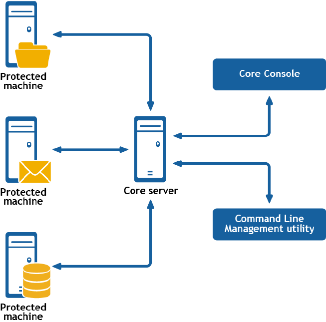
7
Understanding the Rapid Recovery
Command Line Management utility
Dell Data Protection | Rapid Recovery consists of several software components. Key components
relevant to this topic include the following:
• The Rapid Recovery Core manages authentication for protected machines, schedules for transferring
data for backup and replication, export to virtual machines, reporting, and bare metal restore (BMR) to
similar or dissimilar hardware.
• The Rapid Recovery Agent is responsible for volume snapshots and fast transfer of the data to the
repository managed by the Core.
• The Rapid Recovery Command Line Management utility, cmdutil.exe, provides third-party access to
manage system functionality. This tool permits scripting of the Rapid Recovery Core management
functions.
Figure 13. Rapid Recovery Command Line Management provides command-line functions
Rapid Recovery Command Line Management is a Windows command line utility that lets users interact
with the Rapid Recovery Core server. It offers some of the same functions that the Rapid Recovery Core
357

Console graphic user interface provides. For example, Rapid Recovery Command Line Management
utility can mount recovery points or force a snapshot.
The Rapid Recovery Command Line Management utility is embedded in every installation of the Rapid
Recovery Core. To open the Command Line Management utility for a default installation, navigate to the
path C:\Program Files\AppRecovery\Core\CoreService\, and double-click the cmdutil.exe file.
In Command Line mode, action flags can be passed to the Rapid Recovery Command Line Management
utility through a selection of command options and qualifiers to perform limited management functions.
Commands
This section describes the commands and options available for the Rapid Recovery Command Line
Management utility. The following commands are available for use:
•Archive
•CancelActiveJobs
•CheckRepository
•CreateArchiveRepository
•CreateBootCD
•CreateRepository
•DeleteRepository
•Dismount
•DismountArchiveRepository
•EditEsxServer
•Force
•ForceAttach
•ForceChecksum
•ForceLogTruncation
•ForceMount
•ForceReplication
•ForceRollup
•ForceVirtualStandby
•Help
•List
•Mount
•MountArchiveRepository
•NewCloudAccount
•OpenDvmRepository
•Pause
•Protect
•ProtectCluster
•ProtectEsxServer
•RemoveAgent
358

•RemoveArchiveRepository
•RemovePoints
•RemoveScheduledArchive
•RemoveVirtualStandby
•Replicate
•Replication
•RestoreAgent
•RestoreArchive
•RestoreUrc
•Resume
•SeedDrive
•StartExport
•UpdateRepository
•Version
•VirtualStandby
Archive
Businesses often use long-term storage to archive both compliant and non-compliant data. The archive
feature in Rapid Recovery supports extended retention for compliant and non-compliant data. The
administrator can save an archive on the local storage or network location by specifying the -path
parameter and credentials.
Usage
The usage for the command is as follows:
/archive -core [host name] -user [user name] -password [password] -all | -
protectedserver [name | IP address] -path [location] -startdate [time string] -
enddate [time string] -archiveusername [name] -archivepassword [password] -
comment [text]
Command Options
The following table describes the options available for the archive command:
Table 171. Archive command options
Option Description
-? Display this help message.
-core Optional. Remote Core host machine IP address (with an optional port number). By
default, the connection is made to the Core installed on the local machine.
-user Optional. User name for the remote Core host machine. If you specify a user name,
you must also provide a password. If none is provided, then the credentials for the
logged-on user are used.
-password Optional. Password to the remote Core host machine. If you specify a password, you
also have to provide a user name. If none is provided, then the credentials for the
logged-on user are used.
359

Option Description
-all Archive all recovery points for all protected machines on the Core.
-
protectedser
ver
Protected machine with recovery points to be archived. You can specify several
machine names enclosed in double quotes and separated by spaces.
-path Path where archived data should be placed; for example: d:\work\archive or network
path \\servername\sharename.
-startdate Start date for selecting recovery points by creation date. The value must be enclosed
in double quotes; for example, "04/30/2012 02:55 PM".
-enddate Optional. End date for selecting recovery points by creation date. Value must be
enclosed in double quotes; for example, "05/31/2012 11:00 AM". The current time
system is used by default.
-
archiveusern
ame
Optional. User name for the remote machine. Required for network path only.
-
archivepassw
ord
Optional. Password to the remote machine. Required for network path only.
-comment Optional. Comment text must be enclosed in double quotes; for example: -comment
“comment goes here...”.
Examples:
Archive all recovery points with creation dates starting from 04/30/2012 02:55 PM for all machines on the
Core:
>cmdutil /archive -core 10.10.10.10 -user administrator -password 23WE@#$sdd -
path d:\work\archive -startdate “04/30/2012 02:55 PM” -all
Archive recovery points that fall within a date range for two protected machines:
>cmdutil /archive -core 10.10.10.10 -user administrator -password 23WE@#$sdd -
protectedserver "10.20.30.40" "20.20.10.1" -path d:\work\archive -startdate
"04/30/2012 02:55 PM" -enddate "05/31/2012 11:00 AM"
CancelActiveJobs
Use the cancelactivejobs command to cancel the execution of all in-progress jobs of a specific type,
such as transfer or replication.
Usage
The usage for the command is as follows:
/cancelactivejobs -core [host name] -user [user name] -password [password] -
jobtype [job type filter]
Command Options
The following table describes the options available for the cancelactivejobs command:
360

Table 172. CancelActiveJobs command options
Option Description
-? Display help on the command.
-core Optional. Remote core host machine IP address (with an optional port number). By
default, the connection is made to the core installed on the local machine.
-user Optional. User name for the remote Core host machine. If you specify a user name,
you must also provide a password. If none is provided, then the credentials for the
logged-on user are used.
-password Optional. Password to the remote core host machine. If you specify a password, you
must also provide a user name. If none is provided, the logged-in user’s credentials are
used.
-
protectedser
ver
Determines the protected machine on which the jobs should be canceled.
-all Select and cancel events of specified type for all protected servers.
-jobtype Optional. Specifies job type filter. Available values are:
• ‘transfer’ (data transfer)
• ‘repository’ (repository maintenance)
• ‘replication’ (local and remote replications)
• ‘backup’ (backup and restore)
• ‘bootcdbuilder’ (create boot CDs)
• ‘diagnostics’ (upload logs)
• ‘exchange’ (Exchange Server files check)
• ‘export’ (recovery point export)
• ‘pushinstall’ (deploy agents)
• ‘restore’ (recovery point restore)
• ‘rollup’ (recovery point rollups)
• ‘sqlattach’ (agent attachability checks)
• ‘mount’ (mount repository)
By default, all jobs of the specified type are canceled.
Example:
Cancel all transfer jobs on Core 10.10.10.10:
>cmdutil /cancelactivejobs -core 10.10.10.10:8006 -user administrator -password
23WE@#$sdd -jobtype transfer
CheckRepository
You can use the CheckRepository command to verify the integrity of an existing DVM repository created
in AppAssure Core or Rapid Recovery Core.
361

Usage
The usage for the command is as follows:
/checkrepository -repository [repository name] | -all [check all repositories] -
core [host name] -user [user name] -password [password] name] -force
Command Options
The following table describes the options available for the CheckRepository command:
Table 173. CheckRepository command options
Option Description
-? Display this help message.
-core Optional. Remote Core host machine IP address (with an optional port number). By
default, the connection is made to the Core installed on the local machine.
-user Optional. The user name for the remote Core host machine. If you specify a user
name, you must also provide a password. If none is provided, then the credentials for
the logged-on user are used.
-password Optional. The password to the remote Core host machine. If you specify a password,
you also have to provide a user name. If none is provided, then the credentials for the
logged-on user are used.
-all Optional. This option checks all DVM repositories associated with the Core.
-repository The name of the DVM repository.
-force Optional. This option performs the check without your confirmation.
Example:
Start checking the DVM repository:
>cmdutil /checkrepository -repository "Repository1" -core 10.10.10.10 -user
administrator -password 23WE@#$sdd
CreateArchiveRepository
When you create an archive repository, you create a destination for the contents of a scheduled archive.
This feature lets you mount an archived recovery point and restore a machine without importing the
archive.
Usage
The usage for the command is as follows:
/createarchiverepository -core [host name] -user [user name] -password
[password] name] -name [archive repository name] -path [path to the archive] -
archiveusernamme [network user name] -archivepassword [network password] -
cloudaccountname [name of the cloud account] -cloudcontainer [name of the cloud
container]
362

Command Options
The following table describes the options available for the CreateArchiveRepository command:
Table 174. CreateArchiveRepository command options
Option Description
-? Display this help message.
-core Optional. Remote Core host machine IP address (with an optional port number). By
default, the connection is made to the Core installed on the local machine.
-user Optional. The user name for the remote Core host machine. If you specify a user
name, you must also provide a password. If none is provided, then the credentials for
the logged-on user are used.
-password Optional. The password to the remote Core host machine. If you specify a password,
you also have to provide a user name. If none is provided, then the credentials for the
logged-on user are used.
-name Required. The name of the archive repository.
-path The path to the existing archive. It can be a local, network, or cloud location. For
example: d:\work\archive or \\servername\sharename.
-
archiveusern
ame
Optional. This option is the login to the remote machine. It is required for a network
path only.
-
archivepassw
ord
Optional. This option is the password for the remote machine. It is only required for a
network path only.
-
cloudaccount
name
Optional. This option is the display name for an existing cloud account. It is required
for a cloud path only.
-
cloudcontain
er
Optional. The cloud container is where the archive is located. It is required for a cloud
path only.
Examples:
Create an archive repository with the name "NewArchive:"
>cmdutil /createarchiverepository -name NewArchive -core 10.10.10.10 -user
administrator -password 23WE@#$sdd -path d:\work\archive
Additionally, if an archive contains more than one location, then the command should include paths for
all of the segments ordered from 1 to N, where N equals the number of segments.
Create an archive repository with the name "NewSegmentArchive:"
>cmdutil /createarchiverepository -name NewSegmentArchive -path1 \
\RemmoteServer1\Share\Archive\Segment1 - archiveusername1 Administrator -
archivepassword1 23WE@#$sdd -path2 Archives\NewSegment -cloudcontainer2
ArchiveContainer -cloudaccountname AmazonS3Local - path3 d:\work\archive\Third
363

CreateBootCD
This command lets you create a bare metal restore (BMR) boot CD without using the Rapid Recovery
Core Console.
Usage
The usage for the command is as follows:
/createbootcd -ip [IP address] -mask -defaultgateway -dnsserver -vncpassword -
vncport -isofilepath [destination for the boot image]
Command Options
The following table describes the options available for the CreateBootCD command:
Table 175. CreateBootCD command options
Option Description
-? Display this help message.
-ip Optional. This option specifies the IP address of the target BMR machine. By default, it
generates automatically.
-mask Optional. This option specifies the subnet mask of the target BMR machine. By default,
it generates automatically.
-
defaultgatew
ay
Optional. This option specifies the default gateway of the target BMR machine. By
default, it generates automatically.
-dnsserver Optional. This option specifies the DNS server for the target BMR machine. By default,
it generates automatically.
-vncpassword Optional. This option specifies the user password for an existing UltraVNC account. By
default, this option is empty.
-vncport Optional. This option specifies the port to use for UltraVNC. You can change it only if
you used the -vncpassword option. By default, the port is 5900.
-isofilepath Optional. This option specifies the patch to the boot CD file. The default path is C:
\ProgramData\AppRecovery\Boot CDs.
Example:
Create a boot CD:
>cmdutil /createbootcd -ip 192.168.20.188 -mask 255.255.255.0 -defaultgateway
192.168.20.2 -dnsserver 192.168.20.2 -isofilepath D:\bcd\newbcd3.iso
CreateRepository
Use the createrepository command to create a new DVM repository on a local machine or on a CIFS
share location.
364

Usage
The usage for the command when creating a repository on a local location is as follows:
/createrepository -name [repository name] -size [size allocated for repository]
-datapath [data path of repository] -metadatapath [metadata path of repository]
-core [host name] -user [user name] -password [password]
The usage for the command when creating a DVM repository on a share location is as follows:
/createrepository -name [repository name] -size [size allocated for repository]
-uncpath [path for data and metadata] -shareusername [user name for share
location] -sharepassword [password for share user name] -concurrentoperations
[number of operations to occur at one time] -core [host name] -user [user name]
-password [password]
Command Options
The following table describes the options available for the createrepository command:
Table 176. CreateRepository command options
Option Description
-? Display help on the command.
-core Optional. Remote core host machine IP address (with an optional port number). By
default, the connection is made to the core installed on the local machine.
-user Optional. User name for the remote Core host machine. If you specify a user name,
you must also provide a password. If none is provided, then the credentials for the
logged-on user are used.
-password Optional. Password to the remote Core host machine. If you specify a password, you
also have to provide a user name. If none is provided, then the credentials for the
logged-on user are used.
-name Repository name.
-size Size of repository storage location. Available units are b, Kb, Mb, Gb, Tb, and Pb.
-datapath For local location only. Determines data path of repository storage location.
-
metadatapath
For local location only. Determines metadata path of repository storage location.
-uncpath For share location only. Determines data and metadata paths of repository storage
location.
-
shareusernam
e
For share location only. Determines the user name to the share location.
-
sharepasswor
d
For share location only. Determines password to share location.
-comment Optional. Description of repository.
365

Option Description
-
concurrentop
erations
Optional. Maximum number of operations that can be pending at one time. Value by
default: 64.
Examples:
Create a DVM repository at a local location:
>cmdutil /createrepository -name “Repository 1” -size 200 Gb -datapath d:
\repository -metadatapath d:\repository -core 10.10.10.10:8006 -user
administrator -password 23WE@#$sdd
Create a DVM repository at a share location:
>cmdutil /createrepository -name “Repository 1” -size 200 Gb -uncpath \\share
\repository -shareusername login -sharepassword pass123 -comment “First
repository.” -concurrentoperations 8 -core 10.10.10.10:8006 -user administrator
-password 23WE@#$sdd
DeleteRepository
You can use the DeleteRepository command to remove an entire DVM repository created in AppAssure
Core or Rapid Recovery Core.
Usage
The usage for the command is as follows:
/deleterepository -core [host name] -user [user name] -password [password]
name] -name [repository name] | -a [all repositories]
Command Options
The following table describes the options available for the DeleteRepository command:
Table 177. DeleteRepository command options
Option Description
-? Display this help message.
-core Optional. Remote Core host machine IP address (with an optional port number). By
default, the connection is made to the Core installed on the local machine.
-user Optional. The user name for the remote Core host machine. If you specify a user
name, you must also provide a password. If none is provided, then the credentials for
the logged-on user are used.
-password Optional. The password to the remote Core host machine. If you specify a password,
you also have to provide a user name. If none is provided, then the credentials for the
logged-on user are used.
-a Optional. This option deletes all DVM repositories associated with the Core.
-name The name of the DVM repository you want to delete.
366

Example:
Delete all DVM repositories:
>cmdutil /deleterepository -a
Delete the repository with the name "RepositoryName:"
>cmdutil /deleterepository -name RepositoryName
Dismount
Use the dismount command to dismount a mounted recovery point specified by the -path option,
dismount points for the selected agent by the -protectedserver parameter, or dismount all mounted
recovery points—-all.
Usage
The usage for the command is as follows:
/dis[mount] -core [host name] -user [user name] -password [password] [-all | -
protectedserver [name | IP address] | -path [location]
Command Options
The following table describes the options available for the dismount command:
Table 178. Dismount command options
Option Description
-? Display this help message.
-core Optional. Remote core host machine IP address (with an optional port number). By
default, the connection is made to the Core installed on the local machine.
-user Optional. User name for the remote Core host machine. If you specify a user name,
you must also provide a password. If none is provided, then the credentials for the
logged-on user are used.
-password Optional. Password to the remote Core host machine. If you specify a password, you
also have to provide a user name. If none is provided, then the credentials for the
logged-on user are used.
-all Dismount all mounted recovery points.
-
protectedser
ver
Dismount all mounted recovery points for current agent.
-path Dismount selected mount point.
Example:
Dismount a recovery point that was mounted to folder c:\mountedrecoverypoint:
>cmdutil /dismount -core 10.10.10.10 -user administrator -password 23WE@#$sdd -
path c:\mountedRecoveryPoint
367

DismountArchiveRepository
After retrieving the information you want from a mounted archive, you should dismount the archive to
avoid potential issues.
Usage
The usage for the command is as follows:
/dismountarchiverepository -core [host name] -user [user name] -password
[password] name] -name [archive repository name]
Command Options
The following table describes the options available for the DismountArchiveRepository command:
Table 179. DismountArchiveRepository command options
Option Description
-? Display this help message.
-core Optional. Remote Core host machine IP address (with an optional port number). By
default, the connection is made to the Core installed on the local machine.
-user Optional. The user name for the remote Core host machine. If you specify a user
name, you must also provide a password. If none is provided, then the credentials for
the logged-on user are used.
-password Optional. The password to the remote Core host machine. If you specify a password,
you also have to provide a user name. If none is provided, then the credentials for the
logged-on user are used.
-name Required. The name of the archive repository.
Examples:
Dismount the repository named "NewArchive:"
>cmdutil /dismountarchiverepository -name NewArchive -core 10.10.10.10 -user
administrator -password 23WE@#$sdd -path d:\work\archive
EditEsxServer
You can use the editesxserver command whenever you want to make changes to the number of
VMware ESX(i) virtual machines that you want to protect agentlessly.
Usage
The usage for the command is as follows:
/editEsxServer -core [host name] -user [user name] -password [password] -
protectedserver [name | IP address] -add | -remove -virtualMachines [virtual
machines collection | all] -autoProtect [object ID or name collection]
368

Command Options
The following table describes the options available for the editesxserver command:
Table 180. EditEsxServer command options
Option Description
-? Display this help message.
-core Optional. Remote Core host machine IP address (with an optional port number). By
default, the connection is made to the Core installed on the local machine.
-user Optional. The user name for the remote Core host machine. If you specify a user
name, you must also provide a password. If none is provided, then the credentials for
the logged-on user are used.
-password Optional. The password to the remote Core host machine. If you specify a password,
you also have to provide a user name. If none is provided, then the credentials for the
logged-on user are used.
-repository Required. The name of the repository that is associated with the Core that you want to
use to protect the virtual machine.
NOTE: You must enclose the name in double quotes.
-
protectedser
ver
Use this option to edit vCenter and ESX(i) objects for a specific protected machine.
-add Use this option to add a specified vCenter or ESXi object.
-remove Use this option to remove a specified vCenter or ESXi object.
-
virtualmachi
nes
Optional. This option lets you list the virtual machines that you want to protect.
-autoprotect Optional. This option lets you list the new virtual machines that you want to
automatically protect.
Examples:
Automatically protect specific vCenter or ESXi objects of a vCenter or ESXi server with the Core:
>cmdutil /editEsxServer -protectedserver 10.10.8.150 -add -autoprotect
"Folder1" "Folder2"
Force
The force command forces a snapshot of a specified protected server. Forcing a snapshot lets you force
a data transfer for the current protected machine. When you force a snapshot, the transfer will start
immediately or will be added to the queue. Only the data that has changed from a previous recovery
point will be transferred. If there is no previous recovery point, all data on the protected volumes will be
transferred.
369

Usage
The usage for the command is as follows:
/force [snapshot] default | [base] [-all | -protectedserver [name | IP
address]] -core [host name] -user [user name] -password [password]
Command Options
The following table describes the options available for the force command:
Table 181. Force command options
Option Description
-? Display this help message.
-force Optional. Type of snapshot to create. Available values: 'snapshot' (incremental
snapshot) and 'base' (base image snapshot). By default, an incremental snapshot is
performed.
-core Optional. Remote Core host machine IP address (with an optional port number). By
default, the connection is made to the Core installed on the local machine.
-user Optional. User name for the remote Core host machine. If you specify a user name,
you must also provide a password. If none is provided, then the credentials for the
logged-on user are used.
-password Optional. Password to the remote Core host machine. If you specify a password, you
also have to provide a user name. If none is provided, then the credentials for the
logged-on user are used.
-all Force snapshots for all machines on the core.
-
protectedser
ver
Force a snapshot for a specific protected machine.
Example:
Force a snapshot for all machines on the Core:
>cmdutil /force snapshot -core 10.10.10.10 -user administrator -password 23WE@#
$sdd -all
ForceAttach
The forceattach command lets you force a SQL database files attachability check. When you force an
attachability check, the check begins immediately.
Usage
The usage for the command is as follows:
/forceattach -core [host name] -user [user name] -password [password] -
protectedserver [name | IP address] -rpn [number | numbers] | -time [time
string]
370

Command Options
The following table describes the options available for the forceattach command:
Table 182. ForceAttach command options
Option Description
-? Display this help message.
-core Optional. Remote Core host machine IP address (with an optional port number). By
default, the connection is made to the Core installed on the local machine.
-user Optional. User name for the remote Core host machine. If you specify a user name,
you must also provide a password. If none is provided, then the credentials for the
logged-on user are used.
-password Optional. Password to the remote Core host machine. If you specify a password, you
also have to provide a user name. If none is provided, then the credentials for the
logged-on user are used.
-
protectedser
ver
Protected machine against which to perform the attachability check.
-rpn The sequential number of a recovery point against which to perform checks (run
command /list rps to obtain the numbers). To perform checks against multiple
recovery points with a single command, you can specify several numbers separated by
spaces.
-time Select a recovery point by its creation time. You must specify the exact time in the
format “mm/dd/yyyy hh:mm tt” (for example, “2/24/2012 09:00 AM”). Keep in mind to
specify the date and time values of the time zone set on your PC.
Example:
Perform attachability checks for recovery points with numbers 5 and 7:
>cmdutil /forceattach -core 10.10.10.10 -user administrator -password 23WE@#
$sdd -protectedserver 10.10.5.22 -rpn 5 7
ForceChecksum
The forcechecksum command lets you force an integrity check of any Exchange Message Databases
(MDBs) present on the specified recovery point or points. When you force a checksum check, the
command begins immediately.
Usage
The usage for the command is as follows:
/forcechecksum -core [host name] -user [user name] -password [password] -
protectedserver [name | IP address] -rpn [number | numbers] -time [time string]
371

Command Options
The following table describes the options available for the forcechecksum command:
Table 183. ForceChecksum command options
Option Description
-? Display this help message.
-core Optional. Remote Core host machine IP address (with an optional port number). By
default, the connection is made to the Core installed on the local machine.
-user Optional. User name for the remote Core host machine. If you specify a user name,
you must also provide a password. If none is provided, then the credentials for the
logged-on user are used.
-password Optional. Password to the remote Core host machine. If you specify a password, you
also have to provide a user name. If none is provided, then the credentials for the
logged-on user are used.
-
protectedser
ver
Protected machine against which to perform the checksum check.
-rpn The sequential number of a recovery point against which to perform checks (run
command /list rps to obtain the numbers). To perform checks against multiple
recovery points with a single command, you can specify several numbers separated by
spaces.
-time Select a recovery point by its creation time. You must specify the exact time in the
format “mm/dd/yyyy hh:mm tt” (for example, “2/24/2012 09:00 AM”). Keep in mind to
specify the date and time values of the time zone set on your PC.
Example:
Perform a checksum check for recovery points with numbers 5 and 7:
>cmdutil /forcechecksum -core 10.10.10.10 -user administrator -password 23WE@#
$sdd -protectedserver 10.10.5.22 -rpn 5 7
ForceLogTruncation
Forcing log truncation lets you perform this job one time, on-demand. It immediately truncates the logs
for the specified SQL Server agent machine.
Usage
The usage for the command is as follows:
/[forcelogtruncation | flt] -core [host name] -user [user name] -password
[password] -protectedserver [name | IP address]
Command Options
The following table describes the options available for the forcelogtruncation command:
372

Table 184. ForceLogTruncation command options
Option Description
-? Display this help message.
-core Optional. Remote Core host machine IP address (with an optional port number). By
default, the connection is made to the Core installed on the local machine.
-user Optional. User name for the remote Core host machine. If you specify a user name,
you must also provide a password. If none is provided, then the credentials for the
logged-on user are used.
-password Optional. Password to the remote Core host machine. If you specify a password, you
also have to provide a user name. If none is provided, then the credentials for the
logged-on user are used.
-
protectedser
ver
Protected machine against which to perform log file truncation.
Example:
Force log truncation for a protected server:
>cmdutil /forcelogtruncation -core 10.10.10.10 -user administrator -password
23WE@#$sdd -protectedserver 10.10.20.20
ForceMount
Use the forcemount command to conduct an one-time recovery point mountability check. This
determines whether or not the specified recovery point or recovery points can be mounted and used to
restore backed up data. You must list either one or more specific recovery points on which to conduct
the check, or a time range during which the recovery points were created.
Usage
The usage for the command is as follows:
/forcemount -core [host name] -user [user name] -password [password] -
protectedserver [name | IP address] -rpn [number | numbers] | -time [time
string]
Command Options
The following table describes the options available for the forcemount command:
Table 185. ForceMount command options
Option Description
-? Display this help message.
-core Optional. Remote Core host machine IP address (with an optional port number). By
default, the connection is made to the Core installed on the local machine.
373

Option Description
-user Optional. User name for the remote Core host machine. If you specify a user name,
you must also provide a password. If none is provided, then the credentials for the
logged-on user are used.
-password Optional. Password to the remote Core host machine. If you specify a password, you
also have to provide a user name. If none is provided, then the credentials for the
logged-on user are used.
-
protectedser
ver
Protected machine against which to perform a mountability check.
-rpn The sequential number of a recovery point against which to perform checks (run
command /list rps to obtain the numbers). To perform checks against multiple
recovery points with a single command, you can specify several numbers separated by
spaces.
-time Select a recovery point by its creation time. You must specify the exact time in the
format “mm/dd/yyyy hh:mm tt” (for example, “2/24/2012 09:00 AM”). Keep in mind to
specify the date and time values of the time zone set on your PC.
Example:
Perform mountability checks for recovery points with numbers 5 and 7:
>cmdutil /forcemount -core 10.10.10.10 -user administrator -password 23WE@#$sdd
-protectedserver 10.10.20.20 -rpn 5 7
ForceReplication
Use the forcereplication command to force a one-time transfer of replicated data from the source
core to the target core. You can replicate one specific protected server or replicate all protected servers.
The protected servers must be already configured for replication.
Usage
The usage for the command is as follows:
/[forcereplication |frep] -core [host name] -user [user name] -password
[password] -targetcore [host name] -all | -protectedserver [name | IP address]
Command Options
The following table describes the options available for the forcereplication command:
Table 186. ForceReplication command options
Option Description
-? Display this help message.
-core Optional. Remote Core host machine IP address (with an optional port number). By
default, the connection is made to the Core installed on the local machine.
374

Option Description
-user Optional. User name for the remote Core host machine. If you specify a user name,
you must also provide a password. If none is provided, then the credentials for the
logged-on user are used.
-password Optional. Password to the remote Core host machine. If you specify a password, you
also have to provide a user name. If none is provided, then the credentials for the
logged-on user are used
-targetcore Host name of the target core against which replication should be forced.
-
protectedser
ver
The protected machine you want to replicate.
-all Force replication for all machines being replicated to the target core.
Example:
Force replication for a protected server on a specific target core:
>cmdutil /forcereplication -target core 10.10.10.10 -protectedserver 10.20.30.40
ForceRollup
Use the forcerollup command to force the rollup of recovery points on a protected machine.
Usage
The usage for the command is as follows:
/[forcerollup | fro] -core [host name] -user [user name] -password [password] -
protectedserver [name | IP address]
Command Options
The following table describes the options available for the forcerollup command:
Table 187. ForceRollup command options
Option Description
-? Display this help message.
-core Optional. Remote Core host machine IP address (with an optional port number). By
default, the connection is made to the Core installed on the local machine.
-user Optional. User name for the remote Core host machine. If you specify a user name,
you must also provide a password. If none is provided, then the credentials for the
logged-on user are used.
-password Optional. Password to the remote Core host machine. If you specify a password, you
also have to provide a user name. If none is provided, then the credentials for the
logged-on user are used
375

Option Description
-
protectedser
ver
Optional. Protected machine against which to perform rollup.
Example:
Force rollup for agent 10.10.10.1 on the Core:
>cmdutil /forcerollup -core 10.10.10.10 - user administrator -password 23WE@#
$sdd -protectedserver 10.10.10.1
ForceVirtualStandby
Exporting data from a protected machine to a virtual machine creates a virtual standby machine. If you
have continuous virtual export set up, you can use this command to force Rapid Recovery to export data
on demand, regardless of the predetermined schedule.
Usage
The usage for the command is as follows:
/forcevirtualstandby -core [host name] -user [user name] -password [password
login] -protectedserver [name] | -all
Command Options
The following table describes the options available for the ForceVirtualStandby command:
Table 188. ForceVirtualStandby command options
Option Description
-? Display this help message.
-core Optional. Remote Core host machine IP address (with an optional port number). By
default, the connection is made to the Core installed on the local machine.
-user Optional. User name for the remote Core host machine. If you specify a user name,
you must also provide a password. If none is provided, then the credentials for the
logged-on user are used.
-password Optional. Password to the remote Core host machine. If you specify a password, you
also have to provide a user name. If none is provided, then the credentials for the
logged-on user are used.
-
protectedser
ver
The name or space-separated names of virtualized machines.
-all This command specifies whether to force all scheduled virtual exports.
Examples:
Force all virtual standby exports:
>cmdutil /forcevirtualstandby -all
376

Force virtual standby for two machines:
>cmdutil /forcevirtualstandby -protectedserver 10.10.35.48 10.10.35.69
Help
The help command displays a list of the available commands and their definitions. It also provides
copyright and version details.
Usage
The usage for the command is as follows:
/help
Example:
Request Command Line help:
>cmdutil /help
List
The list command returns information about all recovery points, active jobs, completed jobs, failed
jobs, invalid (failed) recovery points, valid (passed) recovery points, mounts, protected servers, volumes,
virtualized servers, unprotected volumes, clusters, protection groups, SQL databases, Exchange
databases, replicated servers, and repositories for the specified agent or list of servers currently protected
by the Core. The most recent records return by default. You can list all records or specify how many
records display by using a number parameter. This parameter should contain the letter "l" for the latest
recovery points and "f" for the first recovery point. Each recovery point has its own number, which the
administrator can use for mounting.
Usage
The usage for the command is as follows:
/list [rps | passed | failed | mounts | volumes | protectedservers | activejobs
| completed jobs | failedjobs | virtualizedservers | unprotectedvolumes |
clusters | protectiongroups | sqldatabases | exchangemailstores |
replicatedservers | repositories] -protectedserver [name | IP address] -core
[host name] -user [user name] -password [password] –number [all | l<number> |
f<number> | <number>] -jobtype
Command Options
The following table describes the options available for the list command:
Table 189. List command options
Option Description
-? Display this help message.
-list Select one of the following options:
• all recovery points ('rps')
• valid recovery points ('passed')
• invalid recovery points ('failed')
377

Option Description
• mounts ('mounts')
• protected volumes ('volumes')
• unprotected volumes ('unprotectedvolumes')
• protected machines ('protectedservers')
• active jobs ('activejobs')
• failed jobs ('failedjobs')
• completed jobs ('completedjobs')
• virtualized servers ('virtualizedservers')
• clusters ('clusters')
• protection groups ('protectiongroups')
• SQL Server databases ('sqldatabases')
• MS Exchange databases ('exchangemailstores')
• replicated servers ('replicatedservers')
• repositories (‘repositories’)
-core Optional. Remote Core host machine IP address (with an optional port number). By
default, the connection is made to the Core installed on the local machine.
-user Optional. User name for the remote Core host machine. If you specify a user name,
you must also provide a password. If none is provided, then the credentials for the
logged-on user are used.
-password Optional. Password to the remote Core host machine. If you specify a password, you
also have to provide a user name. If none is provided, then the credentials for the
logged-on user are used.
-all For show jobs only. Display al events of a specific type (active/failed/completed) on
the core server.
-
protectedser
ver
Protected machine with recovery points to display.
-number Optional. Number of data items to display. Use only with the following specifiers: 'rps',
'activejobs', 'completedjobs', 'failedjobs'. Available values are:
• all (fetch all data items)
• l[number] or [number] (fetches top ## data items)
• f[number] (fetches first ## data items)
Only takes effect when displaying recovery points and jobs.
-jobtype Optional. Filter output by job type. Available values include:
• 'transfer' (data transfer)
• 'repository' (repository maintenance)
• 'replication' (local and remote replications)
• 'backup' (backup and restore)
• 'bootcdbuilder' (create boot CDs)
• 'diagnostics' (upload logs)
• 'exchange' (Exchange Server files check)
• 'export' (recovery point export)
• 'pushinstall' (deploy agents)
378

Option Description
• 'restore' (recovery point restores)
• 'rollup' (protected machine rollups)
• 'sqlattach' (agent attachability checks)
• 'mount' (mount repository)
Examples:
List the 30 most recent recovery points:
>cmdutil /list rps -core 10.10.10.10 -user administrator -password 23WE@#$sdd -
protectedserver 10.10.5.22 -number l30
View all failed data transfer jobs performed by a protected machine:
>cmdutil /list failed jobs -core 10.10.10.10 -user administrator -password
23WE@#$sdd -protectedserver 10.10.5.22 -number all -jobtype transfer
Mount
The mount command mounts a snapshot of one or more drives. You can specify whether the mount
should be read, write, or read-only with previous writes. The default selection is read-only.
Usage
The usage for the command is as follows:
/mount -core [host name] -user [user name] -password [password] -
protectedserver [name | IP address] -mounttype [read | write |
readOnlyWithPreviousWrites] -drives [drive names] -volumes [volume names] -path
[location] -rpn [number | numbers] | -time [time string]
Command Options
The following table describes the options available for the mount command:
Table 190. Mount command options
Option Description
-? Display this help message.
-core Optional. Remote Core host machine IP address (with an optional port number). By
default, the connection is made to the Core installed on the local machine.
-user Optional. User name for the remote Core host machine. If you specify a user name,
you must also provide a password. If none is provided, then the credentials for the
logged-on user are used.
-password Optional. Password to the remote Core host machine. If you specify a password, you
also have to provide a user name. If none is provided, then the credentials for the
logged-on user are used.
-
protectedser
ver
Protected machine with a recovery point or points to be mounted.
379

Option Description
-mounttype Optional. Specifies a mount mode. Available values are 'read' (read-only),
'readOnlyWithPreviousWrites' (read-only with previous writes), 'write'
(writable). The default mode is read-only.
-volumes Optional. List of volume names to mount. If not specified, all volumes are mounted.
Values must be enclosed in double quotes and separated by spaces; for example: "c:"
"d:". Do not use trailing slashes in volume names.
-path Path to a folder on the core server to which the recovery point should be mounted. If
one does not exist, a folder is automatically created.
-rpn Optional. The sequential number of a recovery point to mount (use /list rps
command to get the numbers). Specify several space-separated numbers to mount
multiple recovery points with a single command. In this case data from each recovery
point will be stored in a separate child folder. Note: if neither option -time nor -rpn is
specified then the most recent recovery point that successfully passed integrity check
will be mounted.
-time Optional. Determines recovery point or points to be selected for mount. Available
values include: 'latest', 'passed', exact time in the format "mm/dd/yyyy hh:mm tt" (for
instance, "2/24/2012 09:00 AM"). Keep in mind to specify date time values of the time
zone set on your PC. If neither the -time option nor the -rpn option is specified, then
the most recent recovery point that successfully passed an integrity check is mounted.
-localdrive Optional. Perform mount to user disk on local PC.
Examples:
Mount the most recent recovery points containing volumes “c:\” and “d:\” in the read-only mode:
>cmdutil /mount -core 10.10.10.10 -user administrator -password 23WE@#$sdd -
protectedserver 10.10.5.22 -path c:\mountedrecoverypoint -mounttype read -
volumes "c:" "d:"
Mount recovery points with numbers 2 and 7:
>cmdutil /mount -core 10.10.10.10 -user administrator -password 23WE@#$sdd -
protectedserver 10.10.5.22 -path c:\mountedrecoverypoint -rpn 2 7
MountArchiveRepository
To restore data from an archive in Rapid Recovery, you must first mount it.
Usage
The usage for the command is as follows:
/mountarchiverepository -core [host name] -user [user name] -password
[password] -name [archive repository name]
Command Options
The following table describes the options available for the mountarchiverepository command:
380

Table 191. MountArchiveRepository command options
Option Description
-? Display this help message.
-core Optional. Remote Core host machine IP address (with an optional port number). By
default, the connection is made to the Core installed on the local machine.
-user Optional. The user name for the remote Core host machine. If you specify a user
name, you must also provide a password. If none is provided, then the credentials for
the logged-on user are used.
-password Optional. The password to the remote Core host machine. If you specify a password,
you also have to provide a user name. If none is provided, then the credentials for the
logged-on user are used.
-name Required. The name of the archive repository.
Examples:
Mount the repository named "NewArchive:"
>cmdutil /mountarchiverepository -name NewArchive
NewCloudAccount
Use the NewCloudAccount command to add an account for a cloud provider to the Rapid Recovery
Core. You can then use the account to store archives for retention or replication.
Usage
The usage for the command is as follows:
/newcloudaccount -core [host name] -user [user name] -password [password] -
displayname [name for the account] -type [cloud account provider] -useername
[user name for the account] -key [secret key] -region [region for account]
tenanatid [tenant ID] -authurl [authorization URL]
Command Options
The following table describes the options available for the NewCloudAccount command:
Table 192. NewCloudAccount command options
Option Description
-? Display this help message.
-core Optional. Remote Core host machine IP address (with an optional port number). By
default, the connection is made to the Core installed on the local machine.
-user Optional. The user name for the remote Core host machine. If you specify a user
name, you must also provide a password. If none is provided, then the credentials for
the logged-on user are used.
381

Option Description
-password Optional. The password to the remote Core host machine. If you specify a password,
you also have to provide a user name. If none is provided, then the credentials for the
logged-on user are used.
-displayname The name you want to use for the cloud account.
-type The type of cloud account. Supported values include:
• amazon
• openstack
• rackspace
• windowsazure
• "windows azure"
• azure
-username The user name for the cloud account you want to add. This is the credential you use
in the authentication process. The property has the following variations based on the
cloud type:
• Amazon - Access Key
• OpenStack - User Name
• Rackspace - User Name
• Windows Azure - Storage Account Name
-key The authentication key for the cloud account you want to add. This is the credential
you use in the authentication process. The property has the following variations based
on the cloud type:
• Amazon - Secret Key
• OpenStack - API Key
• Rackspace - API Key
• Windows Azure - Access Key
-region The region of the cloud account you want to add. This option is required only for
OpenStack and Rackspace acocunts.
-tenantid The ID you use to authenticate an OpenStack cloud account. This option is required
only for OpenStack accounts.
-authurl The URL you use to authenticate an OpenStack cloud account. This option is required
only for OpenStack accounts.
Examples:
Add a new cloud account with the name "Amazon S3 Account" with the access key "akey" and the secret
key "skey:"
>cmdutil /newcloudaccount -displayname "Amazon S3 Account" -type amazon -
useername akey -key skey
OpenDvmRepository
Use this command to open an existing DVM repository created in AppAssure Core or Rapid Recovery
Core.
382

Usage
The usage for the command is as follows:
/opendvmrepository -localpath [local path] -sharepath [network share path] -
shareusername [user name for network share] -sharepassword [network share
password]
Command Options
The following table describes the options available for the OpenDvmRepository command:
Table 193. OpenDvmRepository command options
Option Description
-? Display this help message.
-localpath The path to the folder with a DVM repository on the local Core.
-sharepath The path to the folder with the DVM repository on a CIFS share.
-
shareusernam
e
The user name you use to log in to the shared folder.
-
sharepasswor
d
The password you use to log in to the shared folder.
Example:
Open an existing DVM repository on the local machine:
>cmdutil /opendvmrepository -localpath E:\Repository
Pause
An administrator can pause snapshots, export to virtual machines, or replicate a Core. The pause
command accepts three parameters: snapshot, vmexport, and replication. Only one parameter can
be specified. A snapshot can be paused until a certain time, if a time parameter is specified.
A user can pause replication in three ways:
• On a source Core for all protected machines.(-[outgoing]).
The administrator must specify the remote machine name with the outgoing replication pairing to
pause outgoing replication on the source Core:
>cmdutil /pause replication /o 10.10.12.10
• On the source Core for a single protected machine.(-protectedserver):
>cmdutil /pause replication /protectedserver 10.10.12.97
• On target Core (-incoming).
If the local Core is a target Core, the administrator can pause replication by specifying the source
Core using the incoming parameter:
>cmdutil /pause replication /i 10.10.12.25
383

Usage
The usage for the command is as follows:
/pause [snapshot | vmexport | replication] -core [host name] -user [user name] -
password [password] -all | -protectedserver [name | IP address] -incoming [host
name] | outgoing [host name] -time [time string]
Command Options
The following table describes the options available for the pause command:
Table 194. Pause command options
Option Description
-? Display this help message.
-pause [snapshots], [replication] or [vmexport].
-core Optional. Remote Core host machine IP address (with an optional port number). By
default, the connection is made to the Core installed on the local machine.
-user Optional. User name for the remote Core host machine. If you specify a user name,
you must also provide a password. If none is provided, then the credentials for the
logged-on user are used.
-password Optional. Password to the remote Core host machine. If you specify a password, you
also have to provide a user name. If none is provided, then the credentials for the
logged-on user are used.
-all Optional. Pause all agents on the selected Core.
-
protectedser
ver
Optional. Pause current protected server.
-incoming Optional. Host name of the remote core that replicates to the core machine.
-outgoing Optional. Host name of the remote target core to which data is replicated.
-time Optional. The time in the format ‘Day-Hours-Minutes’ when the snapshots will be
resumed (only for snapshots pause).
Examples:
Pause creating snapshots for a specific protected server:
>cmdutil /pause snapshot -core 10.10.10.10 -user administrator -password 23WE@#
$sdd -protectedserver 10.10.10.4
Pause creating snapshots for a protected machine and resume it after three days, 20 hours, and 50
minutes:
>cmdutil /pause snapshot -core 10.10.10.10 -user administrator -password 23WE@#
$sdd -protectedserver 10.10.10.4 -time 3-20-50
384

Pause export to virtual machine for all protected machines on the core:
>cmdutil /pause vmexport -core 10.10.10.10 /user administrator -password 23WE@#
$sdd –all
Pause outgoing replication on the core for a specific protected machine:
>cmdutil /pause replication –core 10.10.10.10 -user administrator -password
23WE@#$sdd –protectedserver 10.10.1.76
Pause outgoing replication for all protected machines on the target core:
>cmdutil /pause replication -core 10.10.10.10 -user administrator -password
-23WE@#$sdd –outgoing 10.10.1.63
Pause incoming replication for all machines on the target core:
>cmdutil /pause replication –core 10.10.10.10 -user administrator -password
23WE@#$sdd –incoming 10.10.1.82
Protect
The protect command adds a server under protection by a core.
Usage
The usage for the command is as follows:
/protect -core [host name] -user [user name] -password [password] -repository
[name] -agentname [name | IP address] -agentusername [user name] -agentpassword
[password] -agentport [port] -volumes [volume names]
Command Options
The following table describes the options available for the protect command:
Table 195. Protect command options
Option Description
-? Display this help message.
-core Optional. Remote Core host machine IP address (with an optional port number). By
default, the connection is made to the Core installed on the local machine.
-user Optional. User name for the remote Core host machine. If you specify a user name,
you must also provide a password. If none is provided, then the credentials for the
logged-on user are used.
-password Optional. Password to the remote Core host machine. If you specify a password, you
also have to provide a user name. If none is provided, then the credentials for the
logged-on user are used.
-repository Name of a repository on the Core to which the protected machine data should be
stored. The name must be enclosed in double quotes.
-agentname Name or IP address of the server you want to protect.
385

Option Description
-
agentusernam
e
User name for the server to be protected.
-
agentpasswor
d
Password for the server to be protected.
-agentport Protected server port number.
-volumes List of volumes to protect. Values must be enclosed in double quotes and separated
by a space. Do not use trailing slashes in volume names; for example: “c:” “d:”.
Example:
Protect specific volumes of a server with the Core:
>cmdutil /protect -core 10.10.10.10 -username administrator -password 23WE@#
$sdd -repository “Repository 1” -agentname 10.10.9.120 -agentport 5002 -
agentusername administrator agentpassword 12345 -volumes “c:” “d:”
ProtectCluster
The protectcluster command adds a cluster under protection by a core.
Usage
The usage for the command is as follows:
/protectcluster -core [host name] -user [user name] -password [password] -
repository [name] -clustername [name | IP address] -clusterusername [user name]
-clusterpassword [password] -clusterport [port] -clustervolumes [volume names] -
clusternodes [cluster nodes collection]
Command Options
The following table describes the options available for the protectcluster command:
Table 196. ProtectCluster command options
Option Description
-? Display this help message.
-core Optional. Remote Core host machine IP address (with an optional port number). By
default, the connection is made to the Core installed on the local machine.
-user Optional. User name for the remote Core host machine. If you specify a user name,
you must also provide a password. If none is provided, then the credentials for the
logged-on user are used.
-password Optional. Password to the remote Core host machine. If you specify a password, you
also have to provide a user name. If none is provided, then the credentials for the
logged-on user are used.
-repository Name of a repository on the Core to which the protected machine data should be
stored. The name must be enclosed in double quotes.
386

Option Description
-clustername Name or IP address of the cluster you want to protect.
-
clusterusern
ame
User name for the cluster to be protected.
-
clusterpassw
ord
Password for the cluster to be protected.
-clusterport Protected cluster server port number.
-
clustervolum
es
List of volumes to protect. Values must be enclosed in double quotes and separated
by a space. Do not use trailing slashes in volume names; for example: “c:” “d:”.
-
clusternodes
List of the cluster nodes and the volumes you want to protect on each node.
Example:
Protect specific volumes of a cluster server with the Core:
>cmdutil /protectcluster -core 10.10.10.10 -username administrator -password
23WE@#$sdd -repository “Repository 1” -clustername 10.10.8.150 -clusterport
8006 -clusterusername clusterAdmin clusterpassword password -volumes “C:
\ClusterStorage\Volume1” -clusternodes nodeName 10.10.8.150 volumes “c:”
nodeName 10.10.8.151 volumes “c:”
ProtectEsxServer
You can use the protectesxserver command whenever you want to add a VMware ESX(i) virtual
machine to protection.
Usage
The usage for the command is as follows:
/protectesxserver -core [host name] -user [user name] -password [password] -
repository [repository name] -server [name | IP address] -serverusername [user
name] -serverpassword [password for server login] -serverport [port] -
virtualMachines [virtual machines collection | all] -autoProtect [object ID or
name collection]
Command Options
The following table describes the options available for the protectesxserver command:
Table 197. ProtectEsxServer command options
Option Description
-? Display this help message.
-core Optional. Remote Core host machine IP address (with an optional port number). By
default, the connection is made to the Core installed on the local machine.
387

Option Description
-user Optional. The user name for the remote Core host machine. If you specify a user
name, you must also provide a password. If none is provided, then the credentials for
the logged-on user are used.
-password Optional. The password to the remote Core host machine. If you specify a password,
you also have to provide a user name. If none is provided, then the credentials for the
logged-on user are used.
-repository Required. The name of the repository that is associated with the Core that you want to
use to protect the virtual machine.
NOTE: You must enclose the name in double quotes.
-server The name or IP address for the vCenter or ESXi server you want to protect.
-
serveruserna
me
The user name for logging in to the vCenter or ESXi server that you want to protect.
-
serverpasswo
rd
The password for logging in to the vCenter or ESXi server that you want to protect.
-serverport Optional. The port number for the vCenter or ESXi server that you want to protect.
-
virtualmachi
nes
Optional. This option lets you list the virtual machines that you want to protect.
-autoprotect Optional. This option lets you list new virtual machines that you want to automatically
protect.
Examples:
Protect specific virtual machines from a vCenter or ESXi server with the Core:
>cmdutil /protectesxserver -core 10.10.10.10 -user admin -password password -
repository "Repository 1" -server 10.10.8.150 -serverport 443 -serverusername
root -serverpassword password -virtualmachines "VM1" "VM2" -autoprotect
"Folder1"
RemoveAgent
The RemoveAgent command lets you remove a protected machine from the protection of a Core and
optionally delete the recovery points of the removed machine. If you do not delete the recovery points,
Rapid Recovery retains and labels them as a recovery points only machine.
Usage
The usage for the command is as follows:
/removeagent -core [host name] -user [user name] -password [password] -
protectedserver [name | IP address] -deleterecoverypoints
388

Command Options
The following table describes the options available for the RemoveAgent command:
Table 198. RemoveAgent command options
Option Description
-? Display this help message.
-core Optional. Remote Core host machine IP address (with an optional port number). By
default, the connection is made to the Core installed on the local machine.
-user Optional. User name for the remote Core host machine. If you specify a user name,
you must also provide a password. If none is provided, then the credentials for the
logged-on user are used.
-password Optional. Password to the remote Core host machine. If you specify a password, you
also have to provide a user name. If none is provided, then the credentials for the
logged-on user are used.
-
protectedser
ver
The name or IP address of the server you want to remove from protection.
-
deleterecove
rypoints
Optional. Deletes all recovery points for the machine you want to remove.
Example:
Remove a machine from protection and delete the associated recovery points:
>cmdutil /removeagent -protectedserver 10.10.1.1 -deleterecoverypoints
RemoveArchiveRepository
You can use the removearchiverepository command to delete a repository from the Rapid Recovery
Core.
Usage
The usage for the command is as follows:
/removearchiverepository -core [host name] -user [user name] -password
[password] name] -name [archive repository name]
Command Options
The following table describes the options available for the removearchiverepository command:
389

Table 199. RemoveArchiveRepository command options
Option Description
-? Display this help message.
-core Optional. Remote Core host machine IP address (with an optional port number). By
default, the connection is made to the Core installed on the local machine.
-user Optional. The user name for the remote Core host machine. If you specify a user
name, you must also provide a password. If none is provided, then the credentials for
the logged-on user are used.
-password Optional. The password to the remote Core host machine. If you specify a password,
you also have to provide a user name. If none is provided, then the credentials for the
logged-on user are used.
-name Required. The name of the archive repository.
Examples:
Remove the repository named "NewArchive" from the local Core:
>cmdutil /removearchiverepository -name NewArchive
RemovePoints
The removepoints command lets you delete specific recovery points of a protected machine.
Usage
The usage for the command is as follows:
/removepoints -core [host name] -user [user name] -password [password] -
protectedserver [name | IP address] -rpn [number | numbers] | -time [time
string]
Command Options
The following table describes the options available for the removepoints command:
Table 200. RemovePoints command options
Option Description
-? Display this help message.
-core Optional. Remote Core host machine IP address (with an optional port number). By
default, the connection is made to the Core installed on the local machine.
-user Optional. User name for the remote Core host machine. If you specify a user name,
you must also provide a password. If none is provided, then the credentials for the
logged-on user are used.
-password Optional. Password to the remote Core host machine. If you specify a password, you
also have to provide a user name. If none is provided, then the credentials for the
logged-on user are used.
390

Option Description
-
protectedser
ver
The name or IP address of the server for which you want to delete recovery points
-rpn Optional. The sequential number of a recovery point to be deleted (use /list rps
command to get the numbers). Specify several space-separated numbers to delete
multiple recovery points with a single command.
-time Optional. Determines which recovery point or points to delete by creation time.
Specify the exact time in the format "mm/dd/yyyy hh:mm tt" (for example, "2/24/2012
09:00 AM"). Keep in mind to specify the date time values of the time zone set on your
PC.
Example:
Delete the recovery points with number 5 and 7:
>cmdutil /removepoints -core 10.10.10.10 -user administrator -password 23WE@#
$sdd -protectedserver 10.10.5.22 -rpn 5 7
RemoveScheduledArchive
Use this command to discontinue an existing Rapid Recoveryscheduled continuous archive.
Usage
The usage for the command is as follows:
/removescheduledarchive -core [host name] -user [user name] -password
[password] name] -all -ids [id | id1 id2]
Command Options
The following table describes the options available for the removescheduledarchive command:
Table 201. RemoveScheduledArchive command options
Option Description
-? Display this help message.
-core Optional. Remote Core host machine IP address (with an optional port number). By
default, the connection is made to the Core installed on the local machine.
-user Optional. The user name for the remote Core host machine. If you specify a user
name, you must also provide a password. If none is provided, then the credentials for
the logged-on user are used.
-password Optional. The password to the remote Core host machine. If you specify a password,
you also have to provide a user name. If none is provided, then the credentials for the
logged-on user are used.
-all This option specifies whether to remove all scheduled archives associated with this
Core.
391

Option Description
-ids Use this option to list the ID or IDs for each scheduled archive you want to remove.
Separate multiples IDs with spaces.
Examples:
Remove all scheduled archives:
>cmdutil /removescheduledarchive -all
Remove one scheduled archive:
>cmdutil /removescheduledarchive -ids 6c123c39-5058-4586-bd0c-7c375e72017b
RemoveVirtualStandby
Use this command to discontinue the continuous export of data to a virtual machine in the Rapid
Recovery command utility.
Usage
The usage for the command is as follows:
/removevirtualstandby -core [host name] -user [user name] -password [password
login] -protectedserver [name] | -all
Command Options
The following table describes the options available for the removevirtualstandby command:
Table 202. RemoveVirtualStandby command options
Option Description
-? Display this help message.
-core Optional. Remote Core host machine IP address (with an optional port number). By
default, the connection is made to the Core installed on the local machine.
-user Optional. User name for the remote Core host machine. If you specify a user name,
you must also provide a password. If none is provided, then the credentials for the
logged-on user are used.
-password Optional. Password to the remote Core host machine. If you specify a password, you
also have to provide a user name. If none is provided, then the credentials for the
logged-on user are used.
-
protectedser
ver
The name or space-separated names of virtualized machines.
-all This command specifies whether to remove all scheduled virtual exports.
Examples:
Remove all virtual standby exports:
>cmdutil /removevirtualstandby -all
392

Remove virtual standby export for two machines:
>cmdutil /removevirtualstandby -protectedserver 10.10.35.48 10.10.35.69
Replicate
Use the Replicate command to set up replication between two Rapid Recovery Cores.
Usage
The usage for the command is as follows:
/replicate -request [email | email customer ID] -targetserver [host name |
hostname port | hostname user name password | hostname port user name password]
-replicationname [name] -seeddrive [localpath | network path username password]
[comment] -protectedserver [name | name repository]
Command Options
The following table describes the options available for the Replicate command:
Table 203. Replicate command options
Option Description
-? Display this help message.
-core Optional. Remote Core host machine IP address (with an optional port number). By
default, the connection is made to the Core installed on the local machine.
-user Optional. User name for the remote Core host machine. If you specify a user name,
you must also provide a password. If none is provided, then the credentials for the
logged-on user are used.
-password Optional. Password to the remote Core host machine. If you specify a password, you
also have to provide a user name. If none is provided, then the credentials for the
logged-on user are used
-request Optional. Specify this option if you want to use a subscription to a third-party provider
of off-site backup and disaster recovery services.
-
targetserver
The name of the server where you want to establish replication. It includes the
following parameters:
• port
• user name
• password
The port parameter is optional, with a default of 8006. If you used the request
option, you should also use the user name and password for the target server.
-
replicationn
ame
Optional. Use the name of the replication job if you do not use the request option.
-seeddrive Optional. Use this option to specify a seed drive for the initial data transfer. The
comment parameter is optional.
393

Option Description
-
protectedser
ver
The list of protected machines you want to replicate. If you use the request option,
list only the names or IP addresses of protected machines. Otherwise, list both
protected machines and the corresponding remote repository name.
Example:
Replicate two protected machines to the remote Core using a seed drive from a network share:
>cmdutil /replicate -targetserver 10.10.1.100 Administrator 123Q -
replicationname ReplicationName -seeddrive Network \\10.10.1.100\seeddrive
Administrator 123Q -protectedserver 10.10.1.1 Repository1 10.10.1.2 Repository2
Replication
Use the replication command to control existing replication between two Rapid Recovery Cores and
manage pending replication requests.
NOTE: This command succeeds the Replicate command, which establishes the connection—
called pairing—between the Cores and uses a seed drive for the initial data transfer. For more
information about this command, see Replicate.
Usage
The usage for the command is as follows:
/replication [-list [incoming | outgoing | pending] -accept | -deny | -ignore |
-delete | -edit] -id [replication ID] -protectedserver [name | name repository]
-responsecomment [comment] -deleterecoverypoints -scheduletype [type] -
dailystarttime [time] -dailyendtime [time] -weekdaystarttime [time] -
weekdayendtime [time] -weekendstarttime [time] -weekendendtime [time]
Command Options
The following table describes the options available for the replication command:
Table 204. Replication command options
Option Description
-? Display this help message.
-core Optional. Remote Core host machine IP address (with an optional port number). By
default, the connection is made to the Core installed on the local machine.
-user Optional. User name for the remote Core host machine. If you specify a user name,
you must also provide a password. If none is provided, then the credentials for the
logged-on user are used.
-password Optional. Password to the remote Core host machine. If you specify a password, you
also have to provide a user name. If none is provided, then the credentials for the
logged-on user are used
-list The list of incoming or outgoing replication jobs or pending replication requests.
-accept Accepts the replication request.
394

Option Description
-deny Denies the replication request.
-ignore Ignores the replication request.
-delete Use this option to delete an existing replication job or a machine from the replication
job. Specify only the -id parameter to delete an entire replication relationship, or
specify both the -id and -protectedserver parameters to delete only specific
machines from replication.
-edit Edits the schedule of existing replication jobs.
-id The identifier for the replication job or pending replication request. It can be a remote
Core ID, host name, customer ID, email address, or pending replication request ID.
-
protectedser
ver
When responding to a replication request, use this option to apply your response to
list of protected servers with a repository name or ID. Use the parameter "all" to apply
response to all requested machines.
-
responsecomm
ent
The comment you provide with the response to a pending replication request.
-
deleterecove
rypoints
Use this option if specific recovery points from a deleted replicated machine should
also be removed.
-
scheduletype
If you use the -edit option, this option specifies the type of replication schedule.
Include one of the following four values:
• atalltimes - Automatically replicate at any time.
• daily - Replicate daily. Specify the -dailystarttime and -dailyendtime
parameters.
• custom - When using daily replication, use this value to schedule replication on
weekdays or weekends. Specify the -weekdaystarttime, -weekdayendtime, -
weekendstarttime, and -weekendendtime parameters.
-
dailystartti
me
Use only for the daily value of the -scheduletype option. It is used to establish a
window of time for when replication should occur. Use this option to specify the
earliest time of day when you want replication to start.
-
dailyendtime
Use only for the daily value of the -scheduletype option. It is used to establish a
window of time for when replication should occur. Use this option to specify the latest
time of day when you want replication to start.
-
weekdaystart
time
Use only for the custom value of the -scheduletype option. It is used to establish a
window of time for when replication should occur. Use this option to specify the
earliest time of a weekday when you want replication to start.
-
weekdayendti
me
Use only for the custom value of the -scheduletype option. It is used to establish a
window of time for when replication should occur. Use this option to specify the latest
time of a weekday when you want replication to start.
-
weekendstart
time
Use only for the custom value of the -scheduletype option. It is used to establish a
window of time for when replication should occur. Use this option to specify the
earliest time of the weekend when you want replication to start.
395

Option Description
-
weekendendti
me
Use only for the custom value of the -scheduletype option. It is used to establish a
window of time for when replication should occur. Use this option to specify the latest
time of the weekend when you want replication to start.
Example:
List all incoming replication:
>cmdutil /replication -list incoming
Accept pending replication requests for two protect machines:
>cmdutil /replication -accept -id customer@email.address -protectedserver
10.10.1.1 Repository1 10.10.1.2 Repository2 -responsecomment A response comment
Deny a pending replication request:
>cmdutil /replication -deny -id customer@email.address
Delete existing replication with replicated recovery points:
>cmdutil /replication -delete -id RemoteServerHostname -deleterecoverypoints
Remove two machines from existing replication:
>cmdutil /replication -delete -id "156d7a46-8e44-43f4-9ed8-60d998e582bf" -
protectedserver 10.10.1.1 10.10.1.2
Edit schedule of replication with specified weekday and weekend times:
>cmdutil /replication -edit -id RemoteServerHostName -scheduletype custom -
weekdaystarttime "9:00 AM" -weekdayendtime "6:00 PM" -weekendstarttime "9:00
AM" -weekendendtime "6:00 PM"
RestoreAgent
The restoreagent command lets you restore a protected machine or volume from a specific Rapid
Recovery recovery point.
Usage
The usage for the command is as follows:
/restoreagent -protectedserver [name | IP address] -rpn [recovery point number]
-volumes [IDs | names | all] -targetmachine [name] -targetvolume [volume name] -
forcedismount -autorestart
Command Options
The following table describes the options available for the restoreagent command:
396

Table 205. RestoreAgent command options
Option Description
-? Display this help message.
-core Optional. Remote Core host machine IP address (with an optional port number). By
default, the connection is made to the Core installed on the local machine.
-user Optional. User name for the remote Core host machine. If you specify a user name,
you must also provide a password. If none is provided, then the credentials for the
logged-on user are used.
-password Optional. Password to the remote Core host machine. If you specify a password, you
also have to provide a user name. If none is provided, then the credentials for the
logged-on user are used.
-
protectedser
ver
The name or IP address of the server you want to restore.
-rpn The identification number of the recovery point you want to use to restore the
machine. To find the correct number, use the command /list rps.
-volumes The IDs or names of the volumes you want to restore. To restore all protected
volumes, use -volumes all.
-
targetmacchi
ne
The name of the machine to which you want to restore the protected machine.
-
targetvolume
The name or ID of the volume to which you want to restore the machine.
-
forcedismoun
t
Optional. Use this option to force the dismount of the database on demand.
-autorestart Optional. Use this command if restarting an Exchange Server machine is necessary.
Example:
Restore a machine to a protected machine with the IP address 192.168.20.130, including the force
database dismount option:
>cmdutil /restoreagent -protectedserver 192.168.20.130 -rpn 259 -volumes "F:"
"E:" "C:" -targetmachine 192.168.20.174 -targetvolume "E:" "G:" "F:" -
forcedismount
RestoreArchive
This command restores an archive from a local archive or share and places the restored data in a
specified repository.
397

Usage
The usage for the command is as follows:
/restorearchive -core [host name] -user [user name] -password [password] -all |
-protectedserver [name | IP address] -repository [name] -archiveusername [name]
-archivepassword [password] -path [location]
Command Options
The following table describes the options available for the restorearchive command:
Table 206. RestoreArchive command options
Option Description
-? Display this help message.
-core Optional. Remote Core host machine IP address (with an optional port number). By
default, the connection is made to the Core installed on the local machine.
-user Optional. User name for the remote Core host machine. If you specify a user name,
you must also provide a password. If none is provided, then the credentials for the
logged-on user are used.
-password Optional. Password to the remote Core host machine. If you specify a password, you
also have to provide a user name. If none is provided, then the credentials for the
logged-on user are used.
-all Restore data for all protected machines from the archive files.
-
protectedser
ver
Protected machine with recovery points to restore. You can specify several machine
names enclosed in double quotes and separated by spaces.
-repository Name of a repository on the Core to which the restored recovery points should be
placed. The name must be enclosed in double quotes.
-
archiveusern
ame
Optional. User name for the remote machine. Required for network path only.
-
archivepassw
ord
Optional. Password to the remote machine. Required for network path only.
-path Location of the archived data to be restored; for example: d:\work\archive or network
path \\servename\sharename.
Examples:
Restore archived data for all protected servers:
>cmdutil /restorearchive -core 10.10.10.10 -username administrator -password
23WE@#$sdd -all -repository repository1 -path d:\work\archive
398

Restore archived data for specific protected servers:
>cmdutil /restorearchive -core 10.10.10.10 -username administrator -password
23WE@#$sdd -protectedserver “10.10.20.30” “20.10.10.5” -repository repository1 -
path d:\work\archive
RestoreUrc
The restoreurc command lets you restore a protected machine or volume from a specific Rapid
Recovery recovery point to a bare-metal machine using the Universal Recovery Console (URC).
Usage
The usage for the command is as follows:
/restoreurc -protectedserver [name | IP address] -rpn [recovery point number] -
volumes [IDs | names | all] -targetmachine [IP address] -urcpassword [password
from the URC] -targetdisk [disk number | all]
Command Options
The following table describes the options available for the restoreurc command:
Table 207. RestoreUrc command options
Option Description
-? Display this help message.
-core Optional. Remote Core host machine IP address (with an optional port number). By
default, the connection is made to the Core installed on the local machine.
-user Optional. User name for the remote Core host machine. If you specify a user name,
you must also provide a password. If none is provided, then the credentials for the
logged-on user are used.
-password Optional. Password to the remote Core host machine. If you specify a password, you
also have to provide a user name. If none is provided, then the credentials for the
logged-on user are used.
-
protectedser
ver
The name or IP address of the server you want to which you want to restore the URC.
-rpn The identification number of the recovery point you want to use to restore the
machine. To find the correct number, use the command /list rps.
-volumes The IDs or names of the volumes you want to restore. To restore all protected
volumes, use -volumes all.
-
targetmacchi
ne
The name of the machine to which you want to restore the protected machine.
-urcpassword The authentication key from the URC.
-targetdisk The numbers of the disks on which you want to restore the machine. To select all
disks from the machine using the URC, use -targetdisk all.
399

Example:
Restore a machine to disks 0 and 1 of the machine using the URC, when the IP address for the URC
machine is 192.168.20.175:
>cmdutil /restoreurc -protectedserver 192.168.20.130 -rpn 259 -volumes "C:"
"E:" -targetmachine 192.168.20.175 -urcpassword ******** -targetdisk 0 1
Resume
The administrator can use this command to resume snapshots, export to a virtual machine, and replicate.
You must specify your need to resume by a parameter. The following parameters are valid: snapshot,
vmexport, and replication. See Pause for more details.
Usage
The usage for the command is as follows:
/resume [snapshot | vmexport | replication] -core [host name] -user [user name]
-password [password] -all | -protectedserver [name | IP address] -incoming
[host name] | outgoing [host name] -time [time string]
Command Options
The following table describes the options available for the resume command:
Table 208. Resume command options
Option Description
-? Display this help message.
-restore [snapshots], [replication] or [vmexport].
-core Optional. Remote Core host machine IP address (with an optional port number). By
default, the connection is made to the Core installed on the local machine.
-user Optional. User name for the remote Core host machine. If you specify a user name,
you must also provide a password. If none is provided, then the credentials for the
logged-on user are used.
-password Optional. Password to the remote Core host machine. If you specify a password, you
also have to provide a user name. If none is provided, then the credentials for the
logged-on user are used.
-all Resume all agents on the selected Core.
-
protectedser
ver
Resume current protected server.
-incoming Host name of the remote core that replicates to the core machine.
-outgoing Host name of the remote target core to which data is replicated.
400

Examples:
Resume snapshots for specific protected server:
>cmdutil /resume snapshot -core 10.10.10.10 -user administrator -password 23WE@#
$sdd -protectedserver 10.10.10.4
Resume export to a virtual machine for all protected machines on the core:
>cmdutil /resume vmexport –core 10.10.10.10 -user administrator -password 23WE@#
$sdd -all
Resume outgoing replication on the core for a specific protected machine:
>cmdutil /resume replication -core 10.10.10.10 -user administrator -password
23WE@#$sdd -protectedserver 10.10.1.76
Resume outgoing replication for all protected machines on the target core:
>cmdutil /resume replication -core 10.10.10.10 -user administrator -password
23WE@#$sdd -outgoing 10.10.1.63
Resume incoming replication for all machines on the target core:
>cmdutil /resume replication -core 10.10.10.10 -user administrator -password
23WE@#$sdd -incoming 10.10.1.82
SeedDrive
You can use a seed drive for the initial data transfer when you establish Rapid Recovery replication.
Usage
The usage for the command is as follows:
/seeddrive [-list | -startcopy | -startconsume | -abandon] -path [local |
network path] -seeddriveusername [user name] -seeddrivepassword [password] -
remotecore [name] [-targetcore [name or IP] | -protectedserver [name] | -all] -
usecompatibleformat
Command Options
The following table describes the options available for the seeddrive command:
Table 209. SeedDrive command options
Option Description
-? Display this help message.
-core Optional. Remote Core host machine IP address (with an optional port number). By
default, the connection is made to the Core installed on the local machine.
-user Optional. The user name for the remote Core host machine. If you specify a user
name, you must also provide a password. If none is provided, then the credentials for
the logged-on user are used.
401

Option Description
-password Optional. The password to the remote Core host machine. If you specify a password,
you also have to provide a user name. If none is provided, then the credentials for the
logged-on user are used.
-list The list of outstanding seed drives with extended information.
-startcopy Start copying data to the seed drive.
-
startconsume
Start consuming the seed drive.
-abandon Abandon the outstanding seed drive request.
-path The local or network path of the seed drive.
-
seeddriveuse
rname
Optional. The user name for the network location of the seed drive.
-
seeddrivepas
sword
Optional. The password for the network location of the seed drive.
-targetcore Optional. Use only with the -copy option. It is the name or IP address of the remote
Core. All protected machines replicating to this Core receive seed drive recovery
points.
-remotecore Use only with the -consume option. It is the name of the remote Core from which the
seed drive recovery points are created or consumed.
-
protectedser
ver
The name or IP address of the protected machine you are using to create or consume
the seed drive of recovery points. For example: -protectedserver "10.10.60.48"
"10.10.12.101."
-all This option specifies whether to consume or copy all of the available protected
machines.
-
usecompatibl
eformat
The new archiving format offers improved performance, however it is not compatible
with older Cores. Use this option when working with a legacy AppAssure Core.
Examples:
List outstanding seed drives:
>cmdutil /seeddrive -list
Copy two protected machines to the seed drive on the network share:
>cmdutil /seeddrive -startcopy -remotecore TargetCoreName -path \
\10.10.1.1\Share\Seed\ -seeddriveusername Administrator -seeddrivepassword
12345 -usecompatibleformat
Starting consuming the seed drive:
>cmdutil /seeddrive -startconsume -path \\10.10.1.1\Share\Seed\ -
seeddriveusername Adminsitrator -seeddrivepassword 12345 -remotecore
RemoteCoreName
402

Abandon an outstanding seed drive request:
>cmdutil /seeddrive -abandon RemoteCoreHostName
StartExport
The startexport command forces a one-time export of data from a protected machine to a virtual
server. You can export to an ESXi, VMware Workstation, Hyper-V, or VirtualBox virtual machine. If
exporting to ESXi, you must specify thick or thin disk provisioning.
Usage
The usage for the command is as follows:
/startexport -exporttype [esxi | vm | hyperv | vb] -core [host name] -user
[user name] -password [password] -protectedserver [name | IP address] -volumes
[volume names] -rpn [recovery point number | numbers] | -time [time string] -
vmname [virtual machine name] -hostname [virtual host name] -hostport [virtual
hostport number] -hostusername [virtual host user name] -hostpassword [virtual
host password] [-ram [total megabytes] | -usesourceram] -diskprovisioning [thin
| thick] -diskmapping [automatic | manual | withvm] -targetpath [location] -
pathusername [user name] -pathpassword [password] [-uselocalmachine]
Command Options
The following table describes the options available for the startexport command:
Table 210. StartExport command options
Option Description
-? Display this help message.
-exporttype Perform export of data from protected server to an ESXi server ('esxi'), VMware
Workstation server ('vm'), Hyper-V server ('hyperv'), or VirtualBox server ('vb').
-core Optional. Remote Core host machine IP address (with an optional port number). By
default, the connection is made to the Core installed on the local machine.
-user Optional. User name for the remote Core host machine. If you specify a user name,
you must also provide a password. If none is provided, then the credentials for the
logged-on user are used.
-password Optional. Password to the remote Core host machine. If you specify a password, you
also have to provide a user name. If none is provided, then the credentials for the
logged-on user are used.
-
protectedser
ver
Protected machine with recovery points to be exported.
-volumes Optional. List of volume names to be exported. If not specified, all volumes will be
exported. Values must be enclosed in double quotes and separated with spaces; for
example: “c:” “d:”. Do not use trailing slashes in volume names.
-rpn Optional. The sequential number of a recovery point to be exported (use Get-
RecoveryPoints command to get the numbers). If neither the ‘time’ nor the ‘rpn’
option is specified, then the most recent recovery point is exported.
403

Option Description
-time Optional. Determines the recovery point or points to be selected for export. You need
to specify the exact time in the format "mm/dd/yyyy hh:mm tt" (for example,
"2/24/2012 09:00 AM"). Be sure to specify the date time values of the time zone set on
your PC. Note: if neither the 'time' nor the 'rpn' option is specified, then the most
recent recovery point is exported.
-vmname The Windows name of the virtual machine.
-hostname For ESXi and Hyper-V virtual exports only. The virtual server host name.
-
linuxhostnam
e
For VirtualBox exports only. The virtual server host name.
-hostport For ESXi and Hyper-V virtual exports only. The virtual server port number.
-
hostusername
For ESXi and Hyper-V virtual exports only. The user name for the virtual server host.
-
hostpassword
For ESXi and Hyper-V virtual exports only. The password for the virtual server host.
-ram Use this option to allocate a specific amount of RAM on the virtual server.
-
usesourceram
Optional. Use this option to allocate the same amount of RAM on the virtual server
that the source machine contains.
-
diskprovisio
ning
Use this option for ESXi exports only. Optional. The amount of disk space that you
want to allocate on the virtual machine. Use one of the two following specifications:
• Thick - This specification makes the virtual disk as large as the original drive on the
protected machine.
• Thin - This specification allocates the amount of actual disk space occupied on the
original drive with a few additional megabytes.
The default specification is "thin."
-diskmapping Use this option for ESXi exports only. Optional. This option determines how to map
the disks from the protected machine to the virtual machine. Use one of the following
values:
• auto - This value automatically maps the disks.
• manual - This value lets you map the disks manually.
• withvm - This value stores the virtual disks in a datastore that you select.
The default value is "auto."
-targetpath For VMware Workstation and VirtualBox exports only. This option specifies the local or
network path—or Linux path, for VirtualBox only—to the folder where you want to
store the virtual machine files
-
pathusername
For VMware Workstation exports only. It is the user name for the network machine. It
is only required when you specify a network path in the -targetpath option.
-
pathpassword
For VMware Workstation exports only. It is the password for the network machine. It is
only required when you specify a network path in the -targetpath option.
404

Option Description
-
uselocalmach
ine
For Hyper-V exports only. Optional. Use this command to connect to the local Hyper-
V server. This option ignores the -hostname, -hostport, -hostusername, and -
hostpassword options.
Examples:
Export data to an ESXi virtual machine with a specific name and the same amount of RAM and disk size as
the source protected server:
>cmdutil /startexport -exporttype esxi -core 10.10.10.10 -user
administrator -password 23WE@#$sdd -protectedserver 10.10.5.22 -vmname Win2008-
Smith -hostname 10.10.10.23 -hostport 443 -hostusername root -hostpassword
12QWsdxc@# -usesourceram -diskprovisioning thick
Create a VMware Workstation machine file on the local drive with protected data from recovery point #4:
>cmdutil /startexport -exporttype vmstation -core 10.10.10.10 -user
administrator -password 23WE@#$sdd -protectedserver 10.10.5.22 -rpn 4 -vmname
Win2008-Smith -targetpath c:\virtualmachines -ram 4096
Create a Hyper-V machine files to be stored on a remote machine:
>cmdutil /startexport -exporttype hyperv -core 10.10.10.10 -user administrator -
password 23WE@#$sdd -protectedserver 10.10.5.22 -vmlocation \\WIN7-Bobby
\virtualmachines -hostname 10.10.10.23 -hostport 443 -hostusername root -
hostpassword 12QWsdxc@# -ram 4096
UpdateRepository
The updaterepository command adds a new storage location to an existing DVM repository.
Usage
The usage for the command is as follows:
/updaterepository -name [repository name] -size [size of the repository] [-
datapath [data path] -metadatapath [metadata path] | [-uncpath [UNC path] -
shareusername [share user name] -sharepassword [share password] -core [host
name] -user [user name] -password [password]
Command Options
The following table describes the options available for the updaterepository command:
Table 211. UpdateRepository command options
Option Description
-? Display this help message.
-name Repository name.
-size Size of repository storage location. Available units are b, Kb, Mb, Gb, Tb, and Pb.
-datapath For local location only. Determines data path of repository storage location.
405

Option Description
-
metadatapath
For local location only. Determines metadata path of repository storage location.
-uncpath For share location only. Determines data and metadata paths of repository storage
location.
-
shareusernam
e
For share location only. Determines user name to share location.
-
sharepasswor
d
For share location only. Determines password to share location.
-core Optional. Remote Core host machine IP address (with an optional port number). By
default, the connection is made to the Core installed on the local machine.
-user Optional. User name for the remote Core host machine. If you specify a user name,
you must also provide a password. If none is provided, then the credentials for the
logged-on user are used.
-password Optional. Password to the remote Core host machine. If you specify a password, you
also have to provide a user name. If none is provided, then the credentials for the
logged-on user are used.
Examples:
Create a new storage location in a local DVM repository:
>cmdutil /updaterepository -name “Repository 1” -size 200Gb -datapath d:
\repository -metadatapath d:\repository -core 10.10.10.10:8006 -username
administrator -password 23WE@#$sdd
Create a storage location for a DVM repository at a shared location:
>cmdutil /updaterepository -name “Repository 1” -size 200Gb -uncpath \\share
\repository -shareusername login -sharepassword 23WE@#$sdd -core
10.10.10.10:8006 -username administrator -password 23WE@#$sdd
Version
The version command displays information about the version of the Rapid Recovery software installed
on the specified server. If you do not specify a core or protected server, the information returned applies
to the Core on which you are currently working.
Usage
The usage for the command is as follows:
/[version | ver] -protectedserver [name | IP address]
Command Options
The following table describes the options available for the version command:
406

Table 212. Version command options
Option Description
-? Display this help message.
-core Optional. Remote Core host machine IP address (with an optional port number). By
default, the connection is made to the Core installed on the local machine.
-user Optional. User name for the remote Core host machine. If you specify a user name,
you must also provide a password. If none is provided, then the credentials for the
logged-on user are used.
-password Optional. Password to the remote Core host machine. If you specify a password, you
also have to provide a user name. If none is provided, then the credentials for the
logged-on user are used.
-
protectedser
ver
Optional. The protected machine for which you want to view version information. If
you do not specify a protect machine, the return is information about the Core
machine on which you are working.
Example:
Display information about the version of Rapid Recovery installed on the current Rapid Recovery Core:
>cmdutil /version
VirtualStandby
You can use the virtualstandby command to export data from a Rapid Recovery protected machine
to a compatible virtual machine.
Usage
The usage for the command is as follows:
/virtualstandby -edit -exporttype [esxi | vm | hyperv | vb] -core [host name] -
user [user name] -password [password] -protectedserver [name | IP address] -
volumes [volume names] -vmname [virtual machine name] -gen2 -hostname [virtual
host name] -hostport [virtual host port number] -hostusername [virtual host
user name] -hostpassword [virtual host password] [-ram [total megabytes] | -
usesourceram] -diskprovisioning [thin | thick] -diskmapping [automatic | manual
| withvm] -targetpath [location] -pathusername [user name] -pathpassword
[password] [-uselocal machine] -initialexport
Command Options
The following table describes the options available for the virtualstandby command:
Table 213. VirtualStandby command options
Option Description
-? Display this help message.
-exporttype This option exports data from a protected machine to one of the following specified
virtual servers:
• esxi (ESXi)
• vm (VMware Workstation)
407

Option Description
• hyperv (Hyper-V)
• vb (VirtualBox)
-core Optional. Remote Core host machine IP address (with an optional port number). By
default, the connection is made to the Core installed on the local machine.
-user Optional. The user name for the remote Core host machine. If you specify a user
name, you must also provide a password. If none is provided, then the credentials for
the logged-on user are used.
-password Optional. The password to the remote Core host machine. If you specify a password,
you also have to provide a user name. If none is provided, then the credentials for the
logged-on user are used.
-
protectedser
ver
Use this option to specify the protected machine whose recovery points you want to
export.
-volumes Optional. Use this option to list the names of the volumes that you want to export. If
you do not specify volumes, then all volumes in the recovery point will export. Enclose
values in double quotes and separate them with a space; for example: "c:" "d:". Do not
use trailing slashes in volumes names.
-ram Use this option to allocate a specific amount of RAM on the virtual server.
-
usesourceram
Optional. Use this option to allocate the same amount of RAM on the virtual server
that the source machine contains.
-vmname The Windows name of the virtual machine.
-gen2 Optional. This option specifies Generation 2 of the VM server. If you do not specify the
generation, the command uses Generation 1. The following operating systems support
Generation 2:
• Windows
– Windows Server 2012 R2
– Windows 8.1
• Ubuntu Linux
– CentOs
– RHEL
– Oracle Linux 7
-hostname For ESXi and Hyper-V virtual exports only. The virtual server host name.
-
linuxhostnam
e
For VirtualBox exports only. The virtual server host name.
-hostport For ESXi and Hyper-V virtual exports only. The virtual server port number.
-
hostusername
For ESXi and Hyper-V virtual exports only. The user name for the virtual server host.
408

Option Description
-
hostpassword
For ESXi and Hyper-V virtual exports only. The password for the virtual server host.
-
diskprovisio
ning
For ESXi exports only. Optional. The amount of disk space that you want to allocate on
the virtual machine. Use one of the two following specifications:
• Thick - This specification makes the virtual disk as large as the original drive on the
protected machine.
• Thin - This specification allocates the amount of actual disk space occupied on the
original drive with a few additional megabytes.
The default specification is "thin."
-diskmapping For ESXi exports only. Optional. This option determines how to map the disks from the
protected machine to the virtual machine. Use one of the following values:
• auto - This value automatically maps the disks.
• manual - This value lets you map the disks manually.
• withvm - This value stores the virtual disks in a datastore that you select.
The default value is "auto."
-targetpath For VMware Workstation and VirtualBox exports only. This option specifies the local or
network path—or Linux path, for VirtualBox only—to the folder where you want to
store the virtual machine files.
-
pathusername
For VMware Workstation exports only. It is the user name for the network machine. It
is only required when you specify a network path in the -targetpath option.
-
pathpassword
For VMware Workstation exports only. It is the password for the network machine. It is
only required when you specify a network path in the -targetpath option.
-
uselocalmach
ine
For Hyper-V exports only. Optional. Use this command to connect to the local Hyper-
V server. This option ignores the -hostname, -hostport, -hostusername, and -
hostpassword options.
-edit Optional. This option lets you edit existing virtual machines. It ignores the -
exporttype and -initialexport options.
-
initialexpor
t
Optional. This option specifies whether to start an initial on-demand virtual machine
export after you configure a continuous virtual standby.
Examples:
Set up a virtual standby export to an ESXi virtual machine with the name, amount of RAM, and disk size of
the source protected server:
>cmdutil /virtualstandby -exporttype esxi -core 10.10.10.10 -user administrator
-password 23WE@#$sdd -protectedserver 10.10.5.22 -vmname Win2008-Smith -
hostname 10.10.10.23 -hostport 443 -hostusername root -hostpassword 12QWsdxc@# -
usesourceram -diskprovisioning thick
409

Set up a virtual standby export to a VMware Workstation machine file on the local drive:
>cmdutil /virtualstandby -exporttype vm -core 10.10.10.10 -user administrator -
password 23WE@#$sdd -protectedserver 10.10.5.22 -vmname Win2008-Smith -
targetpath c:\virtualmachines -ram 4096
Set up a virtual standby export to a Hyper-V machine files and store them on a remote machine:
>cmdutil /virtualstandby -exporttype hyperv -core 10.10.10.10 -user
adminstrator -password 23WE@#$sdd -protectedserver 10.10.5.22 -vmname Win20008-
Smith -vmlocation \\WIN7-Bobby\virtualmachines -hostname 10.10.10.23 -hostport
443 -hostusername root -hostpassword 12QWsdxc@# -ram 4096
Localization
When running on the same machine on which Rapid Recovery Core is installed, the Rapid Recovery
Command Line Management utility bases its display language on the language set for the Rapid Recovery
Core. In this release, supported languages include English, Chinese (Simplified), French, Korean, German,
Japanese, Portuguese (Brazil), and Spanish.
If the Rapid Recovery Command Line Management utility is installed on a separate machine, English is the
only language supported.
410

A
Core Console references
This appendix includes reference tables that describe many of the functions and icons available in the
Rapid Recovery Core Console. It serves as a supplement to Understanding the Rapid Recovery Core
Console chapter of the Dell Data Protection | Rapid Recovery User Guide.
Viewing the Core Console user interface
The Core Console is the main UI through which users interact with Rapid Recovery. When you log into
the Rapid Recovery Core Console, you see the following elements.
Table 214. UI elements included in the Core Console
UI Element Description
Branding
area
For typical environments, the top left side of the Core Console is branded with the full
product name, including the Dell logo. Clicking anywhere on the branding area results in
the opening of a new tab in the web browser, displaying product documentation on the
Support website.
Button bar The button bar, which appears to the right of the branding area, contains buttons
accessible from anywhere in the Core Console. These buttons launch wizards to
accomplish common tasks such as protecting a machine; performing a restore from a
recovery point; creating, attaching, or importing an archive; or replicating from this source
Core to a target Core.
Each button in the button bar is further described in the Table 215. Button bar buttons and
menus table.
Running
tasks count
Shows how many jobs are currently running. This value is dynamic based on the system
state. When you click the drop-down menu, you see a status summary for all jobs
currently running. By clicking the X for any job, you can choose to cancel that job.
Help drop-
down
menu
The Help menu includes the following options:
•Help. Links to in-product help, which opens in a separate browser window.
•Documentation. Links to Rapid Recovery technical documentation on the Dell Support
website.
•Support. Links to the Dell Support website, providing access to Live Chat, video
tutorials, Rapid Recovery knowledge base articles, frequently asked questions, and
more.
•Quick Start Guide. The Quick Start Guide is a guided flow of suggested tasks to
configure and use Rapid Recovery. The guide opens automatically each time you log in
to the Core Console, unless you disable this feature. You can also open the Quick Start
Guide from the Help menu. For more information about the Quick Start Guide, see
Understanding the Quick Start Guide.
•About. Opens the About Dell Data Protection | Rapid Recovery Core dialog box,
including version information and a description of the software.
411

UI Element Description
Server date
and time
The current time of the machine running the Rapid Recovery Core service appears at the
top right of the Core Console. When you hover your mouse over the time, the server date
also appears. This is the date and time recorded by the system for events such as logging,
scheduling, and reporting. For example, when applying protection schedules, the time
displayed on the Core Console is used. This is true even if the time zone is different on the
database server or on the client machine where the browser is running.
Icon bar The icon bar includes a graphic representation for major functions accessible in the Core
Console. It appears on the left side of the user interface (UI), directly below the branding
area. Clicking the appropriate item in the icon bar takes you to the corresponding section
of the UI where you can manage that function.
Each of the icons in the icon bar is further described in the Table 216. Icon bar table.
Left
navigation
area
The left navigation area appears on the left side of the user interface, below the icon bar.
• The left navigation area contains the text filter and the Protected Machines menu.
• If you have added replication to this Core, then this area contains a Replicated
Machines menu.
• If you have any machines that were removed from protection but for which recovery
points were saved, then this area contains a Recovery Points Only menu.
• If you added any custom groups, then this area contains a Custom Group menu.
• If you attached an archive, then this area contains an attached archives menu.
You can toggle the appearance of the left navigation area on and off. This is helpful when
you need to see more content in the main navigation area of the UI. To hide this section,
click the gray border between the left navigation and main navigation areas. To show this
UI element once more, click the gray border again.
Each of the elements in the left navigation area are further described in the Table 218. Left
navigation area and menus table.
Context-
sensitive
help
From the Rapid Recovery Core Console, each time you click the Help icon (a
blue question mark), a resizable browser window opens with two frames. The
left frame contains a navigation tree showing topics from the Dell Rapid
Recovery User Guide. The right frame displays content for the selected help
topic. At any given time, the help navigation tree expands to show the
location in its hierarchy for the selected topic. You can browse through all
User Guide topics using this context-sensitive help feature. Close the browser
when you are done browsing topics.
You can also open help from the Help option of the Help menu.
Button bar
Details about the button bar appear in the following table.
Table 215. Button bar buttons and menus
UI Element Description
Button bar:
Protect
The Protect button launches the Protect Machine Wizard, from which you
can protect a single machine in the Rapid Recovery Core. Additionally, for
412
UI Element Description
button and
menu
other protection options, you can access the drop-down menu next to this
button, which includes the following options.
• The Protect Machine option is another method to launch the Protect
Machine Wizard to protect a single machine.
• The Protect Cluster option allows you to connect to a server cluster.
• The Protect Multiple Machines option opens the Protect Multiple
Machines Wizard to allow you to protect two or more machines
simultaneously.
• The Deploy Agent Software option lets you install the Rapid Recovery
Agent software to one or more machines simultaneously. This function
uses the Deploy Agent Software Wizard.
Button bar:
Restore
button and
menu
The Restore button opens the Restore Machine Wizard to allow you to
restore data from recovery points saved from a protected machine.
Additionally for other restore or export options, you can access the drop-
down menu next to this button, which includes the following options.
• The Restore Machine option is another method to launch the Restore
Machine Wizard to restore data.
• The Mount Recovery Point option launches the Mount Wizard, which lets
you mount recovery points from a protected machine.
• The VM Export option opens the Export Wizard. From this wizard you can
create a virtual machine from recovery points saved in the Rapid Recovery
Core. You have the option of creating a one-time export, or you can
define parameters for a VM that is continually updated after every
snapshot for a protected machine.
Button bar:
Archive
button and
menu
The Archive button opens the Archive Wizard. From this wizard you can
create a one-time archive from selected recovery points, or you can create
an archive and continually save to that archive based on a schedule you
define.
Additionally for other archive options, you can access the drop-down menu
next to this button, which includes the following options.
• The Create Archive option is another method to launch the Create
Archive Wizard to create a one-time archive or to archive continually.
• The Import Archive option launches the Import Archive Wizard, which
lets you import an archive.
• The Attach Archive option mounts an archive so you can read the
contents as a file system.
Button bar:
Replication
button
The Replication button opens the Replication Wizard. From this wizard you
can specify a target Core, select machines protected on your source Core,
and replicate recovery points from selected machines to the target Core in
the repository you specify.
You can pause replication when defining it, or you can have replication begin
immediately.
Additionally, you can specify whether a seed drive will be used to copy data
for existing recovery points to the target Core.
413
Icon bar
Details about the icon bar appear in the following table.
Table 216. Icon bar
UI Element Description
Icon bar The icon bar includes a graphic representation for major functions accessible in the Core
Console. Clicking the appropriate item takes you to the corresponding section of the
user interface where you can manage that function. Icons in the icon bar include:
Icon bar:
Home icon
Home. Click the Home icon to navigate to the Core Home page.
Icon bar:
Replication
icon
Replication. Click the Replication icon to view or manage incoming or
outgoing replication.
Icon bar:
Virtual
Standby icon
Virtual Standby. Click the Virtual Standby icon to export information from
a recovery point to a bootable virtual machine.
Icon bar:
Events icon
Events. Click the Events icon to view a log of all system events related to
the Rapid Recovery Core.
Icon bar:
Settings icon
Settings. Click the Settings icon to view or manage settings for the Rapid
Recovery Core. You can back up or restore Core configuration settings.
You can set general settings to control ports or display aspects.
Additionally, you can configure settings in the following categories:
automatic updates; nightly jobs; transfer queue settings; client timeout
settings; DVM deduplication cache settings; Replay engine settings; and
deploy settings. You can view or change database connections; SMTP
server settings; cloud storage accounts; and change font settings for
reports. You can set SQL attachability settings; core job settings; license
settings; SNMP settings; and vSphere settings.
Icon bar:
More icon
More. Click the More icon to access other important features. Each has
its own icon, listed below.
Icon bar:
More icon
System Info System Info. Click System Info to display data about the
Rapid Recovery Core server. You can see the host name,
OS, architecture and memory for the Core. You can see
the name displayed on the Core Console. You can also
view the fully qualified domain name of the Core on your
network, and the path for your cache metadata and
deduplication caches.
For more information about changing the display name,
see Understanding system information for the Core.
For more information about deduplication cache, see
Understanding deduplication cache and storage locations.
414
UI Element Description
For information on adjusting the settings, see Configuring
DVM deduplication cache settings.
Icon bar:
More icon
Archives Archives. Rapid Recovery lets you manage archives of
information from the Core. You can view information
about scheduled or attached archives, and you can add,
check, or import archives.
Icon bar:
More icon
Mounts Mounts. Lets you view and dismount local mounts, and
view and disconnect remote mounts.
Icon bar:
More icon
Boot CDs Boot CDs. Lets you manage boot CDs, typically used for a
bare metal restore (BMR). You can create a boot CD ISO
image, delete an existing image, or click the path for the
image to open or save it.
Icon bar:
More icon
Repositories Repositories. Lets you view and manage repositories
associated with your Core.
Icon bar:
More icon
Encryption
Keys
Encryption Keys. Lets you view, manage, import, or add
encryption keys that you can apply to protected machines.
If not being used, you can delete encryption keys.
Icon bar:
More icon
Cloud
Accounts
Cloud Accounts. Lets you view and manage connections
between your Core and Cloud storage accounts.
Icon bar:
More icon
Retention
Policy
Retention Policy. Lets you view and modify the Core
retention policy, including how long to keep recovery
points before rolling them up and eventually deleting
them.
Icon bar:
More icon
Notifications Notifications. Lets you configure notifications about Core
events, define SMTP server settings to email notifications,
and set repetition reduction to suppress repeated
notifications about the same event.
Icon bar:
More icon
Downloads Downloads. You can download the Agent software web
installer, the Local Mount Utility, or MIB files containing
event information to use in an SNMP browser.
Icon bar:
More icon
Reports Reports. Lets you access Core reports or schedule reports
to generate on an ongoing basis.
Icon bar:
More icon
Core Log Core Log. Lets you download Core log file for diagnostic
purposes.
Left navigation menu
The full set of menus that may appear in the left navigation area are described in the following table:
415

Table 217. Left navigation menu options
UI Element Description
Protected
Machines menu
The Protected Machines menu appears as the first menu in the left navigation area, if
one or more machines is protected in your Core.
If you click a specific machine name shown in this pane, a Summary page appears,
showing summary information for the selected machine. For more information on
what you can accomplish on the Summary page, see Viewing summary information
for a protected machine.
Replicated
machines menu
If you see the name of another Rapid Recovery Core as a top-level navigation menu,
then the Core on which you are viewing the Core Console is a target Core. The menu
is named after the source Core, and each machine listed under it represents a
machine from that source Core that is replicated on this target.
If this target Core replicates recovery points from more than one source Core, each
source Core appears as its own navigable menu in the left navigation area.
If you click a specific machine name shown in a replicated machines menu, a
Summary page appears, showing summary information for the selected replicated
machine.
For more information about replication, see Replication.
Recovery Points
Only menu
If you see a RECOVERY POINTS ONLY menu, your Core retains recovery points for a
machine it once protected or replicated. While that machine is no longer continuing
to capture new snapshots, the recovery points previously captured on your Core
remain. These recovery points can be used for file-level recovery, but cannot be used
for bare metal restore, for restoring entire volumes, or for adding snapshot data.
Custom groups
menu
If you created any custom groups, a custom group menu appears in the navigation
menu. Custom groups are logical containers used to group machines together (for
example, by function, or organization, or by geographic location). Custom groups can
contain heterogeneous objects (protected machines, replicated machines, and so on).
You can define the label for a custom group; like other menus, the name appears in
the menu in all upper-case letters.
You can perform actions for like items in a custom group by clicking the arrow to the
right of the custom group title. For example, you can force a snapshot for every
protected machine in a custom group.
For more information about creating and managing custom groups, see
Understanding custom groups.
Attached
archives menu
If you attach any archives to your Core, each archive is listed in the left navigation
menu. Its label is the name of the archive. Contained in this list is each machine
included in the archive.
Details about the elements in the left navigation area appear in the following table.
416

Table 218. Left navigation area and menus
UI
Elemen
t
Description
Machin
es
menus
text
filter
The text filter is a text field that lets you filter the items displayed in the Protected
Machines, Replicated Machines, and Recovery-Point Only machines menus. If you
type your criteria in this filter, then only the machines that meet your criteria display
in the appropriate menus.
Expand
and
contrac
t details
Click the arrow to the right of the text filter to expand and contract detail for the
Protected Machines, Replicated Machines, and Recovery-Point Only machines
menus.
Protect
ed
Machin
es
menu
The Protected Machines menu appears in the left navigation area of the UI. In this
menu, you can view any protected machines, protected clusters, or replicated
machines configured in your Core. If you have any protected groups or recovery
point-only machines, these also appear as part of this menu.
You can collapse or expand the view for any of the protected machines in your Core
by clicking the arrow on the left side of this menu label.
The icon displayed portrays the machine type:
• A simple machine icon portrays a physical machine or a protected VM with Rapid
Recovery Agent software installed.
• A multi-machine icon portrays a protected cluster.
• A hollow double-machine icon portrays a VMware VM using agentless
protection.
• A hollow triple-machine icon portrays a VMware vCenter host.
If you click the Protected Machines menu, a Protected Machines page appears,
showing all protected machines on this Core in the Protected Machines pane. For
more information, see Viewing the Protected Machines menu.
Replicat
ed
Machin
es
menu
If replicating machines from another Rapid Recovery Core, the name of that Core
appears as a separate menu under the Protected Machines menu. Each machine
replicated on this target core from the listed source core appears under this menu.
For each replicated machine, the icon indicates the type of machine being
replicated. For example, if replicating a single machine, the icon shows one machine.
If replicating a server cluster, the icon represents a cluster.
You can collapse or expand the view for any of these replicated machines by clicking
the arrow on the left side of this menu label.
From the Replicated Machines menu, you can perform actions on all replicated
machines.
If you click the Replicated Machines menu, the Machines page appears. This page
shows all machines protected on another (source) Core that are replicated to this
target Core. For more information, see Viewing replicated machines from the
navigation menu.
417

UI
Elemen
t
Description
Recove
ry
Points
Only
menu
If any machines previously protected on the Core were removed from protection,
but the recovery points were not deleted, then the Recovery Points Only menu
appears. Each of the formerly protected machines with retained recovery points
displays in this list.
You can collapse or expand the view for any of the recovery points-only machines
by clicking the arrow on the left side of this menu label.
From the Recovery Points Only menu, you can remove the recovery points for all the
recovery-points only machines on this Core.
If you click the Recovery Points Only menu, the Machines page appears, showing the
machines from which the recovery points were saved. For more information, see
Viewing the Recovery Points Only menu.
Custom
Groups
menu
If your Core includes any custom groups, then the left navigation area includes a
Custom Group menu. Each of the objects in that custom group displays in this list.
You can collapse or expand the view for any of the custom groups in your Core by
clicking the arrow on the left side of this menu label.
From the Custom Groups menu, you can perform actions for like items in the group.
If you click the Custom Groups menu, the Machines page appears, showing a pane
for each of the Rapid Recovery objects that appear in your group: protected
machines, replicated machines, and recovery points-only machines. For more
information, see Viewing the Custom Groups menu.
Attache
d
archive
s menu
If you attached any archives to your Core, then the left navigation area includes a
menu for each attached archive. Each of the protected machines included in the
archive displays in this list. The menu label uses the name specified when the archive
was saved.
You can collapse or expand the view for any of the archives attached to your Core
by clicking the arrow on the left side of this menu label.
From the attached archives menu, you can perform actions for like items in the
group.
If you click the attached archives menu, the Machines page appears, showing a pane
for each of the Rapid Recovery objects that appear in your group: protected
machines, replicated machines, and recovery points-only machines. For more
information, see Viewing the Custom Groups menu.
Viewing the Protected Machines pane
The Protected Machines pane contains information about all machines protected on this Rapid Recovery
Core. For each protected machine (if any are protected yet), you see listed in the grid the information
described in the following table.
418

Table 219. Information about each protected machine
UI Element Description
Select item For each row in the summary table, you can select the checkbox to perform actions
from the list of menu options above the table.
Type Shows the machine type.
Status indicator Colored circles in the Status column show whether a machine is online or
unreachable. If you hover the cursor over the colored circle, the status condition is
displayed. Status conditions include green (online and protected), yellow (paused
protection), red (authentication error), and gray (offline or unreachable).
Encryption
status
The lock icon indicates encryption status for the selected protected machine. An open
lock indicates no encryption; a closed lock indicates that encryption keys are
established. For more information on encryption, see Understanding encryption keys.
Display name The display name of the protected machine.
Last snapshot Lists the date and time of the last backup transfer of this machine.
Repository
Name
Lists the repository into which data for this machine are stored.
Recovery Points Lists the number of recovery points and how much space they take in the repository.
Version The version of the Rapid Recovery Agent software loaded on the machine.
Actions When you click the Settings drop-down menu in this column, you see a list of actions
to perform specifically on the selected protected machine.
If any of the machines protected in this Core are configured for virtual standby, then you will see
additional information as described in the following table.
Table 220. Information about protected machines configured for virtual standby
UI Element Description
Last export The date and time of the last virtual export.
Destination The destination for saving the protected machine as a virtual machine. For example,
ESXi, VMware Workstation, Hyper-V, or VirtualBox.
Status Status of machine configured for virtual standby. Status conditions include “In Sync,”
“Paused,” and “Not enabled.”
From the Actions drop-down menu of the Protected Machines pane, you can perform the actions
described in the following table. Some options appear only for an Exchange server or SQL server, as
indicated
419

Table 221. Actions available in the Protected Machines pane
UI Element Description
Force Snapshot Lets you force an incremental snapshot or a base image for all protected volumes on
the selected protected machines. For more information, see Forcing a snapshot.
One-time
Export
Launches the Virtual Machine Export Wizard. This Wizard let you perform a one-time
export of recovery point data from a protected machine to a virtual machine in any
supported VM format. For more information, see VM export.
Virtual Standby Launches the Virtual Machine Export Wizard. This Wizard let you perform a virtual
standby for continual export of recovery point data from a protected machine to a
virtual machine in any supported VM format. For more information, see VM export.
Mount Launches the Mount Wizard. This Wizard let you mount recovery points from the
selected protected machine.
Recovery Points Opens the Recovery Points Summary page.
Restore Launches the Restore Machine Wizard. This process lets you restore data from
recovery point on the Core to a protected machine. For more information, see About
restoring volumes from a recovery point.
Remove
Machine
Removes the selected machine from protection on the Rapid Recovery Core, letting
you choose to either delete or retain the recovery points already on the Rapid
Recovery Core. For more information, see Removing a machine.
You can perform actions on two or more of the machines listed in the protected machines grid. To
perform actions on multiple machines, select the checkbox for each protected machine. Then, from the
menu above the summary table, you can perform any of the actions described in the following table.
Table 222. Additional actions available in the Protected Machines pane when machines are selected
UI Element Description
Force Snapshot Lets you force an incremental snapshot for all protected volumes on the selected
protected machines. For more information, see Forcing a snapshot.
Force Base
Image
Lets you force a base image for all protected volumes on the selected protected
machines. For more information, see Forcing a snapshot.
Protection >
Pause or
Resume
Lets you pause protection for the selected machines (if protection is active), or lets
you resume protection for the selected machines (if protection is paused). For more
information, see Pausing and resuming protection.
Replication Lets you enable, force, copy, pause, or resume replication. You can also copy existing
recovery points to a seed drive. For more information, see Managing replication
settings.
Cancel Lets you cancel all currently active operations for the selected machines, or lets you
cancel snapshots only that are currently taking place for the selected machines. This
does not affect operations scheduled for the future.
Remove
Machines
Removes the selected machine from protection on the Rapid Recovery Core, letting
you choose to either delete or retain the recovery points already on the Rapid
Recovery Core. For more information, see Removing a machine.
420

From the Configuration drop-down menu for each protected machine, you can perform the actions
listed in the following table. Some options appear only for an Exchange server or SQL server, as indicated.
Table 223. Actions available in the Protected Machines pane
UI Element Description
Force Snapshot Lets you force an incremental snapshot or a base image for one or more volumes
on the selected machine. For more information, see Forcing a snapshot.
Force Log
Truncation for
Exchange
For a protected Exchange Server machine, forces truncation of the Exchange logs,
which frees up space on the Exchange server. For more information, see Forcing
log truncation for a SQL machine.
Force Log
Truncation for SQL
For a protected SQL Server machine, forces truncation of the SQL Server logs,
which identifies free space on the SQL server. For more information, see Forcing
log truncation for a SQL machine.
Export Launches the Export Wizard. This Wizard let you export recovery point data from a
protected machine to a virtual machine in any supported VM format. You can
perform a one-time export or set up virtual standby for continual exports. For
more information, see VM export.
Mount Opens the Mount Recovery Point dialog box, which allows you to browse through
snapshot data saved the Rapid Recovery Core to mount a specific recovery point.
For more information, see Mounting a recovery point or Mounting a recovery point
volume on a Linux machine respectively.
Recovery Points Opens the Recovery Points tab for the selected agent machine. For more
information, see Managing snapshots and recovery points.
Restore Launches the Restore Machine Wizard. This process lets you restore data from
recovery point on the Core to a protected machine. For more information, see
About restoring volumes from a recovery point.
Remove Machine Removes the selected machine from protection on the Rapid Recovery Core,
letting you choose to either delete or retain the recovery points already on the
Rapid Recovery Core. For more information, see Removing a machine.
Viewing events for a protected machine
On the Events page, you can view the jobs that occurred or are in progress for the protected machine
you selected. Buttons at the top of the page let you navigate to lists of jobs in each of the three
categories of activities:
•Tasks. A job that the Rapid Recovery must perform to operate successfully.
•Alerts. A notification related to a task or event that includes errors and warning.
•Journal. A composite of all protected machine tasks and alerts.
The following table includes descriptions of each element on the Events page.
421

Table 224. Events page elements
UI Element Description
Search keyword Lets you search for a specific item within each category. Available for tasks only.
From To narrow your results, you can enter a date at which to begin searching. Available for
tasks only.
To To narrow your results, you can enter a date at which to stop searching. Available for
tasks only.
Status icons Each icon represents a different job status. For alerts and tasks, clicking one of the
icons lets you filter the list by that status, essentially generating a report. Clicking the
icon a second time removes the filter for that status. You can filter by more than one
status. Statuses include:
•Active. A job that is in progress.
•Queued. A job that is waiting for another job to complete before it can initiate.
•Waiting. A job waiting for your approval or completion, such as a seed drive. (For
more information about seed drives, see Replication.)
•Complete. A job that completed successfully.
•Failed. A job that failed and did not complete.
Service icon This button adds services jobs to the list of jobs. When you click this icon, a smaller
service icon appears on each status icon, which lets you filter by service jobs that have
those statuses (if any exist). Examples of services jobs include deleting index files or
removing a machine from protection.
Export type
drop-down list
The drop-down list includes the formats to which you can export the event report.
Available for tasks only. It includes the following formats:
• PDF
• HTML
• CSV
• XLS
• XLSX
(Export
icon)
Converts the event report to the format you selected. Available for tasks only.
Page selection Event reports can include several jobs across multiple pages. The numbers and arrows
at the bottom of the Events page let you navigate the additional pages of the report.
The Events page displays all events in a table. The following table lists the information shown for each
item.
422

Table 225. Detailed information for the Event summary table
UI Element Description
Status Shows the status for the task, alert, or journal item. Available for alerts or journal items,
click the header to filter the results by status.
Name Name is available for tasks only. This text field lists the task type that completed for
this protected machine. Examples include transfer of volumes, maintaining repository,
rolling up, performing mountability checks, performing checksum checks, and so on.
Start Time Available for tasks, alerts, and journal items. Shows the date and time when the job or
task began.
End Time Available for tasks only. Shows the date and time when the task completed.
Job
Details
Available for tasks only. Opens the Monitor Active Task dialog box, so you can view
details of the specific job or task. These details include an ID for the job, rate at which
the core transferred data (if relevant), elapsed time for the job to complete, total work
in amount of gigabytes, and any child tasks associated with the job.
Message Available for alerts and journal items. This text field provides a descriptive message of
the alert or journal item.
Viewing the More menu for a protected machine
The More menu offers additional options to help manage the selected a protected machine. To access
these tools, click the More drop-down menu and select from one of the options described in the
following table.
Table 226. Tools accessible from the More option for a protected machine
UI Element Description
System
Information
Shows information about the protected machine, system information, volumes,
processors, network adapters, and IP addresses for this machine.
For more information, see Viewing system information for a protected machine.
Mounts
From the Local Mounts pane, you can view or dismount volumes mounted locally.
From the Remote Mounts pane, you can view or dismount volumes mounted using
the Local Mount Utility.
For information on dismounting volumes, see Dismounting recovery points.
For information on mounting a recovery point locally, see Mounting a recovery point
or Mounting a recovery point volume on a Linux machine, respectively.
Retention
Policy
Lets you specify a retention policy for the selected machine. You can choose to use
the Core's default policy, or you can differentiate the retention policy for this machine
only. For more information, see Customizing retention policy settings for a protected
machine.
423

UI Element Description
Notifications
Lets you specify a custom notification group for events pertaining to the selected
machine. This does not change the notifications already set on the Core. For more
information, see Configuring notification groups.
Agent Log
Lets you download and view the log file for a machine protected using the Rapid
Recovery Agent software. For more information, see Downloading and viewing the log
file for a protected machine.
424
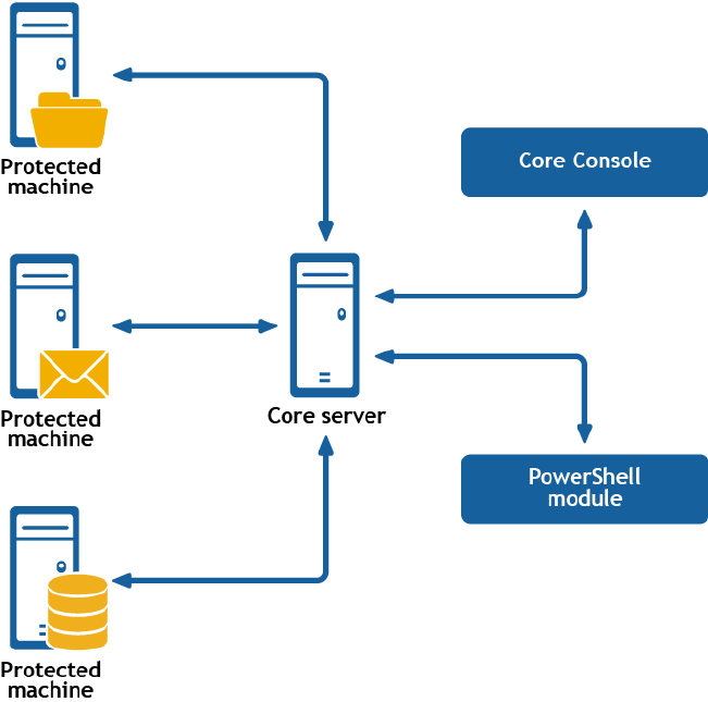
B
Understanding the Rapid Recovery
PowerShell module
Dell Data Protection | Rapid Recovery consists of several software components. Key components
relevant to this topic include the following:
• The Rapid Recovery Core manages authentication for protected machines, schedules for transferring
data for backup and replication, export to virtual machines, reporting, and bare metal restore (BMR) to
similar or dissimilar hardware.
• The Rapid Recovery Agent is responsible for taking volume snapshots and for fast transfer of the data
to the repository managed by the Core.
• The Rapid Recovery PowerShell Module is a Windows utility that lets users interact with the Core
server by using Windows PowerShell® scripts. This module offers some of the same functionality that
the Rapid Recovery Core Console graphic user interface (GUI) provides. For example, the Rapid
Recovery PowerShell Module can mount Rapid Recovery recovery points or force a snapshot of a
protected machine.
Figure 14. The PowerShell module interacts with the Rapid RecoveryCore
425

PowerShell is a Microsoft .NET Framework-connected environment designed for administrative
automation. This section describes the Rapid Recovery PowerShell module and the cmdlets
administrators can use to script certain functions without interaction with the Rapid Recovery Core GUI.
NOTE: You can also run PowerShell scripts as pre and post scripts. For more information and
sample scripts, see Extending Rapid Recovery jobs using scripting.
Prerequisites for using PowerShell
Before using the Rapid Recovery PowerShell module, you must have Windows PowerShell 2.0 or later
installed. Due to new features introduced in PowerShell 3.0, including easier access to object properties,
PowerShell Web access, and support for REST calls, Dell recommends using PowerShell 3.0 or later.
NOTE: Make sure to place the powershell.exe.config file in the PowerShell home directory. For
example, C:\WindowsPowerShell\powershell.exe.config
powershell.exe.config
<?xml version="1.0"?>
<configuration>
<startup useLegacyV2RuntimeActivationPolicy="true">
<supportedRuntime version="v4.0.30319"/>
<supportedRuntime version="v2.0.50727"/>
</startup>
</configuration>
Launching PowerShell and importing the module
Unlike other system modules, the Rapid Recovery PowerShell Module is not loaded by default. For each
session, you can open Windows PowerShell with administrative privileges, and then import the module.
Complete the steps in this procedure to launch PowerShell and import the Rapid Recovery PowerShell
Module.
1. Open an elevated command prompt for Windows PowerShell. For example, type Windows
PowerShell in the Start menu, and for the resulting Windows PowerShell application, right-click and
select Run as administrator.
Windows PowerShell opens in a new command window.
2. Enter the following command and then press Enter:
Import-Module “RapidRecoveryPowerShellModule”
The Rapid Recovery PowerShell module is imported for your current session. You can begin to run
cmdlets in the existing command window.
Working with commands and cmdlets
Cmdlets are specialized commands in a Windows PowerShell script that perform a single function. A
cmdlet is typically expressed as a verb-noun pair. The result returned by a cmdlet is an object.
426

You can pipeline PowerShell commands, which enables the output of one cmdlet to be piped as input to
another cmdlet. As a simple example, you can request the list of commands in the Rapid Recovery
PowerShell module, and sort that list by name. The example script for this is:
Get-Command -module rapidrecoverypowershellmodule | sort-object name
Getting cmdlet help and examples
After you open PowerShell and import the Rapid Recovery PowerShell module, you can request
additional information at any time by using the Get-Help <command_name> cmdlet. For example, to get
information about the virtual machine export cmdlet, enter the following cmdlet and then press Enter:
Get-Help Start-VMExport
The object returned includes the command name, synopsis, syntax, and any options you can use with the
command.
Another method to get help for a specific cmdlet is to type the command name followed by -?. For
example:
Start-VMExport -?
You can also request examples for a cmdlet by executing the following command:
>Get-Help Start-VMExport -examples
Rapid Recovery PowerShell module cmdlets
This section describes the cmdlets and options available in the Rapid Recovery PowerShell Module. All
cmdlets in the Rapid Recovery PowerShell Module support the following common parameters:
• Verbose
• Debug
• ErrorAction
• ErrorVariable
• WarningAction
• WarningVariable
• OutBuffer
• OutVariable
For more information, use Get-Help about_commonparameters.
The available cmdlets are listed in the following table.
427

Table 227. Cmdlets in the Rapid Recovery PowerShell Module
Cmdlet name Description
Edit-
EsxiVirtualStandby
Edit an existing ESXi virtual standby configuration.
Edit-
HyperVVirtualStand
by
Edit an existing Hyper-V virtual standby configuration.
Edit-
VBVirtualStandby
Edit an existing VirtualBox virtual standby configuration.
Edit-
VMVirtualStandby
Edit an existing VMware Workstation virtual standby configuration.
Edit-
ScheduledArchive
Edit an existing scheduled archive configuration.
Get-ActiveJobs Retrieve a collection of active jobs.
Get-
CloudAccounts
Get information about the cloud accounts saved to the Core.
Get-Clusters Retrieve a collection of protected clusters.
Get-
CompletedJobs
Retrieve a collection of completed jobs.
Get-
ExchangeMailStore
s
Retrieve a collection of Exchange mail stores.
Get-Failed Get information about failed recovery points.
Get-FailedJobs Retrieve a collection of failed jobs.
Get-Mounts Show all mounted recovery points.
Get-Passed Get information about passed recovery points.
Get-
ProtectedServers
Get information about protected servers.
Get-
ProtectionGroups
Retrieve a collection of protection groups.
Get-QueuedJobs Retrieve a collection of jobs waiting in the queue.
Get-
RecoveryPoints
Get information about recovery points.
Get-
ReplicatedServers
Get information about replicated servers.
Get-Repositories Get information about repositories.
Get-
ScheduledArchive
Get information about recurring archive jobs.
Get-SqlDatabases Retrieve a collection of SQL databases.
428

Cmdlet name Description
Get-
UnprotectedVolum
es
Retrieve a collection of unprotected volumes.
Get-
VirtualizedServers
Get information about virtualized servers.
Get-Volumes Get information about volumes.
New-Base Force base image snapshot.
New-
CloudAccount
Add a new cloud account to the Core.
New-
EncryptionKey
Create a new encryption key.
New-
EsxiVirtualStandby
Create a new ESXi virtual standby virtual machine.
New-
HyperVVirtualStand
by
Create a new Hyper-V virtual standby virtual machine.
New-Mount Mount recovery points.
New-Replication Set up and force replication.
New-Repository Create new DVM repository.
New-
ScheduledArchive
Schedule a new recurring archive.
New-Snapshot Force snapshot.
New-
VBVirtualStandby
Create a new VirtualBox virtual standby virtual machine.
New-
VMVirtualStandby
Create a new VMware Workstation virtual standby virtual machine.
Push-Replication Force replication.
Push-Rollup Force rollup.
Remove-Agent Remove a machine from protection.
Remove-Mount Dismount recovery point.
Remove-Mounts Dismount all mounted recovery points.
Remove-
RecoveryPoints
Delete recovery points for a protected machine.
Remove-
Repository
Delete an existing DVM repository.
Remove-
ScheduledArchive
Discontinue a scheduled archive.
429

Cmdlet name Description
Remove-
VirtualStandby
Remove a virtual standby virtual machine from the Core.
Resume-
Replication
Resume replication.
Resume-
RepositoryActivity
Resume repository activity.
Resume-
ScheduledArchive
Resume a scheduled archive.
Resume-Snapshot Resume snapshot.
Resume-
VirtualStandby
Resume exporting data to a virtual standby virtual machine.
Start-Archive Archive recovery points.
Start-
AttachabilityCheck
Force attachability check for protected MS SQL databases.
Start-
ChecksumCheck
Force a checksum check for protected Exchange mail stores.
Start-EsxiExport Force export to an ESXi server.
Start-HypervExport Force export to a Hyper-V server.
Start-
LogTruncation
Force log truncation.
Start-
MountabilityCheck
Force mountability check for protected Exchange mail stores.
Start-Protect Put a server under protection.
Start-
ProtectCluster
Put a cluster under protection.
Start-
RepositoryCheck
Force a DVM repository check.
Start-
RestoreArchive
Restore archive with recovery points.
Start-
ScheduledArchive
Force a data transfer for a scheduled archive.
Start-VBExport Force export to a VirtualBox server.
Start-
VirtualStandby
Force a data transfer to an existing virtual standby virtual machine.
Start-VMExport Force export to a VMWare Workstation server.
Stop-ActiveJobs Cancel active jobs.
Suspend-
Replication
Pause replication.
430

Cmdlet name Description
Suspend-
RepositoryActivity
Pause activity for a repository.
Suspend-
ScheduledArchive
Pause data transfers for a scheduled archive.
Suspend-Snapshot Pause snapshot.
Suspend-
VirtualStandby
Pause data transfers to a virtual standby virtual machine.
Update-Repository Add extent to DVM repository.
Edit-EsxiVirtualStandby
The Edit-EsxiVirtualStandby command lets you use PowerShell to make changes to an existing
virtual export to an ESXi virtual machine (VM).
Usage
The usage for the command is as follows:
Edit-EsxiVirtualStandby [-HostName <String>] [-HostPort <String>] [-
HostUserName <String>] [-HostPassword <String>] [-DiskProvisioning <String>] [-
DiskMapping <String>] [-ProtectedServer <String>] [-Volumes <String[]>] [-
VMName <String>] [-UseSourceRam] [-Ram <String>] [-User <String>] [-Core
<String>] [-Password <String>] [-Verbose] [-Debug] [-
ErroAction<ActionPreference>] [-WarningAction<ActionPreference>] [-
ErrorVariable String>] [-WarningVariable <String> [-OutVariable <String>] [-
OutBuffer <Int32>]
Command Options
The following table describes the options available for the Edit-EsxiVirtualStandby command:
Table 228. Edit-EsxiVirtualStandby command options
Option Description
-? Display this help message.
-core Optional. Remote Core host machine IP address (with an optional port number). By
default the connection is made to the Core installed on the local machine.
-user Optional. User name for the remote Core host machine. If you specify a user name,
you also have to provide a password.
If none are provided, then the logged-on user's credentials will be used.
-password Optional. Password to the remote Core host machine. If you specify a password, you
also have to provide a log on.
If none are provided, then the logged-on user's credentials will be used.
-
protectedser
ver
Show jobs for a specific protected machine, indicated by IP address.
431

Option Description
-all Show all jobs, including those performed by the Core and all protected servers.
-number Optional. Determine how many records to display. available values are:
all (display all jobs); l[number] or [number] (fetches ## most recent jobs sorted by
execution and time); f[number] (displays first ## recovery jobs sorted by execution
and time). By default, the 20 most recent jobs are shown.
-jobtype Optional. Specifies the job type filter. Available values are: 'transfer' (data transfer),
'repository' (repository maintenance), 'replication' (local and remote
replications), 'backup' (backup and restore), 'bootcdbuilder' (create boot CDs),
'diagnostics' (upload logs), 'exchange' (Exchange Server files check), 'export'
(recovery point export), 'pushinstall' (deploy agents), 'rollback' (restoring
from a recovery point), 'rollup' (recovery point rollups), 'sqlattach' (agent
attachability checks), and 'mount' (mount repository). By default, all jobs of the
specified type are returned.
-time Optional. Filter output by date and time for the job started. Available types of input
include:
#d or DD (where # is a number for the period of time of days before now until now)
#h or #H (where # is number for the period of hours before now until now)
“time date 1”, “time date 2” (to show a custom range of time from a specific date
appearing before the comma to a specific date following the comma).
Example:
Lists all active jobs on the local Core:
>Get-activejobs –all
Edit-HyperVVirtualStandby
The Edit-HyperVVirtualStandby command lets you use PowerShell to make changes to an existing
virtual export to a Hyper-V virtual machine (VM).
Usage
The usage for the command is as follows:
Edit-HyperVVirtualStandby [-HostName <String>] [-HostPort <String>] [-
HostUserName <String>] [-HostPassword <String>] [-VMLocation <String>] [-
UseLocalMachine] [-gen2] [-UseVhdx] [-ProtectedServer <String>] [-Volumes
<String[]>] [-VMName <String>] [-UseSourceRam] [-Ram <String>] [-User <String>]
[-Core <String>] [-Password <String>] [-Verbose] [-Debug] [-ErrorAction
<ActionPreference>] [-WarningAction <ActionPreference>] [-ErrorVariable
<String>] [-WarningVariable <String>] [-OutVariable <String>] [-OutBuffer
<Int32>]
Command Options
The following table describes the options available for the Edit-HyperVVirtualStandby command:
432

Table 229. Edit-HyperVVirtualStandby command options
Option Description
-? Display this help message.
-core Optional. Remote Core host machine IP address (with an optional port number). By
default the connection is made to the Core installed on the local machine.
-user Optional. User name for the remote Core host machine. If you specify a user name,
you also have to provide a password.
If none are provided, then the logged-on user's credentials will be used.
-password Optional. Password to the remote Core host machine. If you specify a password, you
also have to provide a log on.
If none are provided, then the logged-on user's credentials will be used.
-
protectedser
ver
Show jobs for a specific protected machine, indicated by IP address.
-all Show all jobs, including those performed by the Core and all protected servers.
-number Optional. Determine how many records to display. available values are:
all (display all jobs); l[number] or [number] (fetches ## most recent jobs sorted by
execution and time); f[number] (displays first ## recovery jobs sorted by execution
and time). By default, the 20 most recent jobs are shown.
-jobtype Optional. Specifies the job type filter. Available values are: 'transfer' (data transfer),
'repository' (repository maintenance), 'replication' (local and remote
replications), 'backup' (backup and restore), 'bootcdbuilder' (create boot CDs),
'diagnostics' (upload logs), 'exchange' (Exchange Server files check), 'export'
(recovery point export), 'pushinstall' (deploy agents), 'rollback' (restoring
from a recovery point), 'rollup' (recovery point rollups), 'sqlattach' (agent
attachability checks), and 'mount' (mount repository). By default, all jobs of the
specified type are returned.
-time Optional. Filter output by date and time for the job started. Available types of input
include:
#d or DD (where # is a number for the period of time of days before now until now)
#h or #H (where # is number for the period of hours before now until now)
“time date 1”, “time date 2” (to show a custom range of time from a specific date
appearing before the comma to a specific date following the comma).
Example:
Lists all active jobs on the local Core:
>Get-activejobs –all
433

Edit-ScheduledArchive
The Edit-ScheduledArchive command lets you use PowerShell to make changes to an existing
scheduled archive.
Usage
The usage for the command is as follows:
Edit-ScheduledArchive -core [host name] -user [login] -password [password] -all
| -protectedserver [name | IP address | "[name1 | IP address1]" "[name2 | IP
address2]"] -path [location] -cloudaccountname [name] -cloudcontainer [name] -
recycleaction [type] -scheduletype [type] -dayofweek [name] -dayofmonth
[number] -time [time] -initialpause -id [id]
Command Options
The following table describes the options available for the Edit-ScheduledArchive command:
Table 230. Edit-ScheduledArchive command options
Option Description
-? Display this help message.
-core Optional. Remote Core host machine IP address (with an optional port number). By
default the connection is made to the Core installed on the local machine.
-user Optional. User name for the remote Core host machine. If you specify a user name,
you also have to provide a password.
If none are provided, then the logged-on user's credentials will be used.
-password Optional. Password to the remote Core host machine. If you specify a password, you
also have to provide a log on.
If none are provided, then the logged-on user's credentials will be used.
-
protectedser
ver
The protected machine with recovery points that you want to archive. You can specify
multiple machine names enclosed in double quotes and separated by commas.
-all Archive recovery points for all protected machines.
-path The path to where to save the archived data. For example:
• Local machine: "d:\work\archive"
• Network path: "\\servername\sharename"
• Folder in a cloud account: "Folder Name"
NOTE: The number of symbols should not be greater than 100 for local and
network locations, and should not be greater than 150 for a cloud location.
-
cloudaccount
name
Optional. Use only for cloud archiving. The name of the cloud account where you
want to save the archive.
434

Option Description
-
cloudcontain
er
Optional. Use only for cloud archiving. The name of the cloud container in the chosen
cloud account, where the archive will be saved. When you use this option, you should
also specify the "-cloudaccountname" parameter.
-
recycleactio
n
The type of recycle action. Specified by using one of the following four values:
• "replacethiscore" - Overwrites any pre-existing archived data pertaining to this
Core, but leaves the data for other Cores intact.
• "erasecompletely" - Clears all archived data from the directory before writing the
new archive.
• "incremental" - Lets you add recovery points to an existing archive. It compares
recovery points to avoid duplicating data that already exists in the archive.
-
scheduletype
Type of schedule interval. Specified the option with one of the following four values:
• "daily" - For a daily automatically created archive.
• "weekly" - For a weekly automatically created archive. You must specify the "-
dayofweek" parameter.
• "monthly" - For a monthly automatically created archive. You must specify the "-
dayofmonth" parameter. If a month does not have the day specified—for example,
"31"—then the archive will not occur for that month.
• "lastdayofmonth" - For automatically creating an archive on the last day of each
month.
-dayofweek Use only for the "weekly" option of the "-scheduletype" parameter. The day of the
week on which to automatically create the archive (for example, "Monday").
-dayofmonth Use only for the "month" option of the "-scheduletype" parameter. The day (number)
of the month on which to automatically create the archive (for example, "15").
-time The hour of the day when you want to create an archive.
-
initialpause
Optional. Specify this option if you want to initially pause archiving after you configure
the archiving schedule.
-id The identifier of the scheduled archive that you want to edit.
Example:
Edit a scheduled archive on the local Core:
>Edit-ScheduledArchive -protectedserver protectedserver1 -path d:\work\archive -
cloudaccountname cloud1 -cloudcontainer cloudarchives -recycleaction
incremental -scheduletype daily -time 12:00 AM -initialpause -i
d archiveid
Edit-VBVirtualStandby
The Edit-VBVirtualStandby command lets you use PowerShell to make changes to an existing virtual
export to a VirtualBox virtual machine (VM).
435

Usage
The usage for the command is as follows:
Edit-VBVirtualStandby [-TargetPath <String>] [-PathUserName <String>] [-
PathPassword <String>] [-LinuxHostName <String>] [-HostPort <UInt32>] [-
AccountUserName <String>] [-AccountPassword <String>] [-ProtectedServer
<String>] [-Volumes <String[]>] [-VMName <String>] [-UseSourceRam] [-Ram
<String>] [-User <String>] [-Core <String>] [-Password <String>] [-Verbose] [-
Debug] [-ErrorAction <ActionPreference>] [-WarningAction <ActionPreference>] [-
ErrorVariable <String>] [-WarningVariable <String>] [-OutVariable <String>] [-
OutBuffer <Int32>]
Command Options
The following table describes the options available for the Edit-VBVirtualStandby command:
Table 231. Edit-VBVirtualStandby command options
Option Description
-? Display this help message.
-core Optional. Remote Core host machine IP address (with an optional port number). By
default the connection is made to the Core installed on the local machine.
-user Optional. User name for the remote Core host machine. If you specify a user name,
you also have to provide a password.
If none are provided, then the logged-on user's credentials will be used.
-password Optional. Password to the remote Core host machine. If you specify a password, you
also have to provide a log on.
If none are provided, then the logged-on user's credentials will be used.
-
protectedser
ver
Show jobs for a specific protected machine, indicated by IP address.
-all Show all jobs, including those performed by the Core and all protected servers.
-number Optional. Determine how many records to display. available values are:
all (display all jobs); l[number] or [number] (fetches ## most recent jobs sorted by
execution and time); f[number] (displays first ## recovery jobs sorted by execution
and time). By default, the 20 most recent jobs are shown.
-jobtype Optional. Specifies the job type filter. Available values are: 'transfer' (data transfer),
'repository' (repository maintenance), 'replication' (local and remote
replications), 'backup' (backup and restore), 'bootcdbuilder' (create boot CDs),
'diagnostics' (upload logs), 'exchange' (Exchange Server files check), 'export'
(recovery point export), 'pushinstall' (deploy agents), 'rollback' (restoring
from a recovery point), 'rollup' (recovery point rollups), 'sqlattach' (agent
attachability checks), and 'mount' (mount repository). By default, all jobs of the
specified type are returned.
436

Option Description
-time Optional. Filter output by date and time for the job started. Available types of input
include:
#d or DD (where # is a number for the period of time of days before now until now)
#h or #H (where # is number for the period of hours before now until now)
“time date 1”, “time date 2” (to show a custom range of time from a specific date
appearing before the comma to a specific date following the comma).
Example:
Lists all active jobs on the local Core:
>Get-activejobs –all
Edit-VMVirtualStandby
The Edit-VMVirtualStandby command lets you use PowerShell to make changes to an existing virtual
export to a VMware Workstation virtual machine (VM).
Usage
The usage for the command is as follows:
Edit-VMVirtualStandby [-TargetPath <String>] [-PathUserName <String>] [-
PathPassword <String>] [-ProtectedServer <S
tring>] [-Volumes <String[]>] [-VMName <String>] [-UseSourceRam] [-Ram
<String>] [-User <String>] [-Core <String>]
[-Password <String>] [-Verbose] [-Debug] [-ErrorAction <ActionPreference>]
[-WarningAction <ActionPreference>] [-Er
rorVariable <String>] [-WarningVariable <String>] [-OutVariable <String>] [-
OutBuffer <Int32>]
Command Options
The following table describes the options available for the Edit-VMVirtualStandby command:
Table 232. Edit-VMVirtualStandby command options
Option Description
-? Display this help message.
-core Optional. Remote Core host machine IP address (with an optional port number). By
default the connection is made to the Core installed on the local machine.
-user Optional. User name for the remote Core host machine. If you specify a user name,
you also have to provide a password.
If none are provided, then the logged-on user's credentials will be used.
-password Optional. Password to the remote Core host machine. If you specify a password, you
also have to provide a log on.
If none are provided, then the logged-on user's credentials will be used.
437

Option Description
-
protectedser
ver
Show jobs for a specific protected machine, indicated by IP address.
-all Show all jobs, including those performed by the Core and all protected servers.
-number Optional. Determine how many records to display. available values are:
all (display all jobs); l[number] or [number] (fetches ## most recent jobs sorted by
execution and time); f[number] (displays first ## recovery jobs sorted by execution
and time). By default, the 20 most recent jobs are shown.
-jobtype Optional. Specifies the job type filter. Available values are: 'transfer' (data transfer),
'repository' (repository maintenance), 'replication' (local and remote
replications), 'backup' (backup and restore), 'bootcdbuilder' (create boot CDs),
'diagnostics' (upload logs), 'exchange' (Exchange Server files check), 'export'
(recovery point export), 'pushinstall' (deploy agents), 'rollback' (restoring
from a recovery point), 'rollup' (recovery point rollups), 'sqlattach' (agent
attachability checks), and 'mount' (mount repository). By default, all jobs of the
specified type are returned.
-time Optional. Filter output by date and time for the job started. Available types of input
include:
#d or DD (where # is a number for the period of time of days before now until now)
#h or #H (where # is number for the period of hours before now until now)
“time date 1”, “time date 2” (to show a custom range of time from a specific date
appearing before the comma to a specific date following the comma).
Example:
Lists all active jobs on the local Core:
>Get-activejobs –all
Get-ActiveJobs
The Get-ActiveJobs command returns all active jobs from the Core. The -jobtype parameter could
be used to observe specific jobs.
Usage
The usage for the command is as follows:
Get-ActiveJobs -core [host name] -user [user name] -password [password] -all |
-protectedserver [server name or IP address] -number [all | f[number] |
l[number] | number] -jobtype [type] -time [time]
Command Options
The following table describes the options available for the Get-ActiveJobs command:
438

Table 233. Get-ActiveJobs command options
Option Description
-? Display this help message.
-core Optional. Remote Core host machine IP address (with an optional port number). By
default the connection is made to the Core installed on the local machine.
-user Optional. User name for the remote Core host machine. If you specify a user name,
you also have to provide a password.
If none are provided, then the logged-on user's credentials will be used.
-password Optional. Password to the remote Core host machine. If you specify a password, you
also have to provide a log on.
If none are provided, then the logged-on user's credentials will be used.
-
protectedser
ver
Show jobs for a specific protected machine, indicated by IP address.
-all Show all jobs, including those performed by the Core and all protected servers.
-number Optional. Determine how many records to display. available values are:
all (display all jobs); l[number] or [number] (fetches ## most recent jobs sorted by
execution and time); f[number] (displays first ## recovery jobs sorted by execution
and time). By default, the 20 most recent jobs are shown.
-jobtype Optional. Specifies the job type filter. Available values are: 'transfer' (data transfer),
'repository' (repository maintenance), 'replication' (local and remote
replications), 'backup' (backup and restore), 'bootcdbuilder' (create boot CDs),
'diagnostics' (upload logs), 'exchange' (Exchange Server files check), 'export'
(recovery point export), 'pushinstall' (deploy agents), 'rollback' (restoring
from a recovery point), 'rollup' (recovery point rollups), 'sqlattach' (agent
attachability checks), and 'mount' (mount repository). By default, all jobs of the
specified type are returned.
-time Optional. Filter output by date and time for the job started. Available types of input
include:
#d or DD (where # is a number for the period of time of days before now until now)
#h or #H (where # is number for the period of hours before now until now)
“time date 1”, “time date 2” (to show a custom range of time from a specific date
appearing before the comma to a specific date following the comma).
Example:
Lists all active jobs on the local Core:
>Get-activejobs –all
439

Get-Clusters
The Get-Clusters command returns information about server clusters protected in the Core.
Usage
The usage for the command is as follows:
Get-Clusters -core [host name] -user [user name] -password [password]
Command Options
The following table describes the options available for the Get-Clusters command:
Table 234. Get-Clusters command options
Option Description
-? Display this help message.
-core Optional. Remote Core host machine IP address (with an optional port number). By
default the connection is made to the Core installed on the local machine.
-user Optional. User name for the remote Core host machine. If you specify a user name,
you also have to provide a password.
If none are provided, then the logged-on user's credentials will be used.
-password Optional. Password to the remote Core host machine. If you specify a password, you
also have to provide a log on.
If none are provided, then the logged-on user's credentials will be used.
Example:
List server clusters protected on the local Core:
>Get-Clusters
Get-CompletedJobs
The Get-CompletedJobs command returns a list of jobs completed on the Core. The -jobtype
parameter could be used to observe specific jobs.
Usage
The usage for the command is as follows:
Get-CompletedJobs -core [host name] -user [user name] -password [password] -all
|
-protectedserver [server name or IP address] -number [all | f[number] |
l[number] | number] -jobtype [type] -time [time]
Command Options
The following table describes the options available for the Get-CompletedJobs command:
440

Table 235. Get-CompletedJobs command options
Option Description
-? Display this help message.
-core Optional. Remote Core host machine IP address (with an optional port number). By
default the connection is made to the Core installed on the local machine.
-user Optional. User name for the remote Core host machine. If you specify a user name,
you also have to provide a password.
If none are provided, then the logged-on user's credentials will be used.
-password Optional. Password to the remote Core host machine. If you specify a password, you
also have to provide a log on.
If none are provided, then the logged-on user's credentials will be used.
-
protectedser
ver
Show jobs for a specific protected machine, indicated by IP address.
-all Show all jobs, including those performed by the Core and all protected servers.
-number Optional. Determine how many records to display. available values are:
all (display all jobs); l[number] or [number] (fetches ## most recent jobs sorted by
execution and time); f[number] (displays first ## recovery jobs sorted by execution
and time). By default, the 20 most recent jobs are shown.
-jobtype Optional. Specifies the job type filter. Available values are: 'transfer' (data transfer),
'repository' (repository maintenance), 'replication' (local and remote
replications), 'backup' (backup and restore), 'bootcdbuilder' (create boot CDs),
'diagnostics' (upload logs), 'exchange' (Exchange Server files check), 'export'
(recovery point export), 'pushinstall' (deploy agents), 'rollback' (restoring
from a recovery point), 'rollup' (recovery point rollups), 'sqlattach' (agent
attachability checks), and 'mount' (mount repository). By default, all jobs of the
specified type are returned.
-time Optional. Filter output by date and time for the job started. Available types of input
include:
#d or DD (where # is a number for the period of time of days before now until now)
#h or #H (where # is number for the period of hours before now until now)
“time date 1”, “time date 2” (to show a custom range of time from a specific date
appearing before the comma to a specific date following the comma).
Example:
Lists all active jobs on the local Core:
>Get-CompletedJobs –all
Lists all completed create repository jobs on the local Core:
>Get-CompletedJobs –jobtype repository
441

Get-ExchangeMailStores
The Get-ExchangeMailStores command returns information about male stores on Exchange servers
Protected by the Core.
Usage
The usage for the command is as follows:
Get-ExchangeMailStores -core [host name] -user [user name] -password [password]
-protectedserver [server name or IP address]
Command Options
The following table describes the options available for the Get-ExchangeMailStores command:
Table 236. Get-ExchangeMailStores command options
Option Description
-? Display this help message.
-core Optional. Remote Core host machine IP address (with an optional port number). By
default the connection is made to the Core installed on the local machine.
-user Optional. User name for the remote Core host machine. If you specify a user name,
you also have to provide a password.
If none are provided, then the logged-on user's credentials will be used.
-password Optional. Password to the remote Core host machine. If you specify a password, you
also have to provide a log on.
If none are provided, then the logged-on user's credentials will be used.
-
protectedser
ver
Show jobs for a specific protected machine, indicated by IP address.
Example:
Lists Exchange mail stores for Exchange server for the local Core:
>Get-ExchangeMailStores -protectedserver 10.10.10.10
Get-Failed
The Get-Failed command returns information about failed recovery points on the local Core.
Usage
The usage for the command is as follows:
Get-Failed -core [host name] -user [user name] -password [password] -all |
-protectedserver [server name or IP address] -number [all | f[number] |
l[number] | number]
442

Command Options
The following table describes the options available for the Get-Failed command:
Table 237. Get-Failed command options
Option Description
-? Display this help message.
-core Optional. Remote Core host machine IP address (with an optional port number). By
default the connection is made to the Core installed on the local machine.
-user Optional. User name for the remote Core host machine. If you specify a user name,
you also have to provide a password.
If none are provided, then the logged-on user's credentials will be used.
-password Optional. Password to the remote Core host machine. If you specify a password, you
also have to provide a log on.
If none are provided, then the logged-on user's credentials will be used.
-
protectedser
ver
Show jobs for a specific protected machine, indicated by IP address.
-number Optional. Determine how many records to display. available values are:
all (display all jobs); l[number] or [number] (fetches ## most recent jobs sorted by
execution and time); f[number] (displays first ## recovery jobs sorted by execution
and time). By default, the 20 most recent jobs are shown.
Example:
Lists all failed recovery points:
>Get-failed -protectedserver 10.10.10.10
Get-FailedJobs
The Get-FailedJobs command returns all failed jobs from the local Core.
Usage
The usage for the command is as follows:
Get-FailedJobs -core [host name] -user [user name] -password [password] -all |
-protectedserver [server name or IP address] -number [all | f[number] |
l[number] | number] -jobtype [type] -time [time]
Command Options
The following table describes the options available for the Get-FailedJobs command:
443

Table 238. Get-FailedJobs command options
Option Description
-? Display this help message.
-core Optional. Remote Core host machine IP address (with an optional port number). By
default the connection is made to the Core installed on the local machine.
-user Optional. User name for the remote Core host machine. If you specify a user name,
you also have to provide a password.
If none are provided, then the logged-on user's credentials will be used.
-password Optional. Password to the remote Core host machine. If you specify a password, you
also have to provide a log on.
If none are provided, then the logged-on user's credentials will be used.
-
protectedser
ver
Show jobs for a specific protected machine, indicated by IP address.
-all Show all jobs, including those performed by the Core and all protected servers.
-number Optional. Determine how many records to display. available values are:
all (display all jobs); l[number] or [number] (fetches ## most recent jobs sorted by
execution and time); f[number] (displays first ## recovery jobs sorted by execution
and time). By default, the 20 most recent jobs are shown.
-jobtype Optional. Specifies the job type filter. Available values are: 'transfer' (data transfer),
'repository' (repository maintenance), 'replication' (local and remote
replications), 'backup' (backup and restore), 'bootcdbuilder' (create boot CDs),
'diagnostics' (upload logs), 'exchange' (Exchange Server files check), 'export'
(recovery point export), 'pushinstall' (deploy agents), 'rollback' (restoring
from a recovery point), 'rollup' (recovery point rollups), 'sqlattach' (agent
attachability checks), and 'mount' (mount repository). By default, all jobs of the
specified type are returned.
-time Optional. Filter output by date and time for the job started. Available types of input
include:
#d or DD (where # is a number for the period of time of days before now until now)
#h or #H (where # is number for the period of hours before now until now)
“time date 1”, “time date 2” (to show a custom range of time from a specific date
appearing before the comma to a specific date following the comma).
Example:
Lists all failed jobs on the local Core:
>Get-FailedJobs –all
Lists all failed create backup jobs on the local Core:
>Get-FailedJobs -type backup
444

Get-Mounts
The Get-Mounts command returns all recovery points mounted on the local Core.
Usage
The usage for the command is as follows:
Get-Mounts -core [host name] -user [user name] -password [password] -
protectedserver [server name or IP address]
Command Options
The following table describes the options available for the Get-Mounts command:
Table 239. Get-Mounts command options
Option Description
-? Display this help message.
-core Optional. Remote Core host machine IP address (with an optional port number). By
default the connection is made to the Core installed on the local machine.
-user Optional. User name for the remote Core host machine. If you specify a user name,
you also have to provide a password.
If none are provided, then the logged-on user's credentials will be used.
-password Optional. Password to the remote Core host machine. If you specify a password, you
also have to provide a log on.
If none are provided, then the logged-on user's credentials will be used.
-
protectedser
ver
Show jobs for a specific protected machine, indicated by IP address.
Example:
Show all mounted recovery points:
>Get-Mounts -core 10.10.10.10:8006 -user administrator -password 23WE@#$sdd -
protectedserver 10.10.5.22
Get-Passed
The Get-Passed command returns information about recovery points that have passed verification
checks on the Core.
Usage
The usage for the command is as follows:
Get-Passed -core [host name] -user [user name] -password [password] -
protectedserver [server name or IP address] -number [all | f[number] |l[number]
| number]
445

Command Options
The following table describes the options available for the Get-Passed command:
Table 240. Get-Passed command options
Option Description
-? Display this help message.
-core Optional. Remote Core host machine IP address (with an optional port number). By
default the connection is made to the Core installed on the local machine.
-user Optional. User name for the remote Core host machine. If you specify a user name,
you also have to provide a password.
If none are provided, then the logged-on user's credentials will be used.
-password Optional. Password to the remote Core host machine. If you specify a password, you
also have to provide a log on.
If none are provided, then the logged-on user's credentials will be used.
Example:
Lists all recovery points on the local Core the passed verification checks:
>Get-Passed -protectedserver 10.10.10.10
Get-ProtectedServers
The Get-ProtectedServers command information about machines protected on the local Core.
Usage
The usage for the command is as follows:
Get-ProtectedServers -core [host name] -user [user name] -password [password]
Command Options
The following table describes the options available for the Get-ProtectedServers command:
Table 241. Get-ProtectedServers command options
Option Description
-? Display this help message.
-core Optional. Remote Core host machine IP address (with an optional port number). By
default the connection is made to the Core installed on the local machine.
-user Optional. User name for the remote Core host machine. If you specify a user name,
you also have to provide a password.
If none are provided, then the logged-on user's credentials will be used.
446

Option Description
-password Optional. Password to the remote Core host machine. If you specify a password, you
also have to provide a log on.
If none are provided, then the logged-on user's credentials will be used.
Example:
Lists all machines currently protected on the local Core:
>Get-ProtectedServers
Get-ProtectionGroups
The Get-ProtectionGroups command returns information about protection groups on the local Core.
Usage
The usage for the command is as follows:
Get-ProtectionGroups -core [host name] -user [user name] -password [password] -
all |
-protectedserver [server name or IP address]
Command Options
The following table describes the options available for the Get-ProtectionGroups command:
Table 242. Get-ProtectionGroups command options
Option Description
-? Display this help message.
-core Optional. Remote Core host machine IP address (with an optional port number). By
default the connection is made to the Core installed on the local machine.
-user Optional. User name for the remote Core host machine. If you specify a user name,
you also have to provide a password.
If none are provided, then the logged-on user's credentials will be used.
-password Optional. Password to the remote Core host machine. If you specify a password, you
also have to provide a log on.
If none are provided, then the logged-on user's credentials will be used.
-
protectedser
ver
Show jobs for a specific protected machine, indicated by IP address.
Example:
Lists protection groups on the local Core:
>Get-ProtectionGroups -protectedserver 10.10.10.10
447

Get-QueuedJobs
The Get-QueuedJobs command returns all jobs waiting to begin from the Core.
Usage
The usage for the command is as follows:
Get-QueuedJobs -core [host name] -user [login] -password [password] -all | -
protectedserver [name | IP address] -nu
mber [all | f[number] | l[number] | number] -jobtype [type] -time [time]
Command Options
The following table describes the options available for the Get-ActiveJobs command:
Table 243. Get-ActiveJobs command options
Option Description
-? Display this help message.
-core Optional. Remote Core host machine IP address (with an optional port number). By
default the connection is made to the Core installed on the local machine.
-user Optional. User name for the remote Core host machine. If you specify a user name,
you also have to provide a password.
If none are provided, then the logged-on user's credentials will be used.
-password Optional. Password to the remote Core host machine. If you specify a password, you
also have to provide a log on.
If none are provided, then the logged-on user's credentials will be used.
-
protectedser
ver
Show jobs for a specific protected machine, indicated by IP address.
-all Show all jobs, including those performed by the Core and all protected servers.
-number Optional. Determine how many records to display. available values are:
all (display all jobs); l[number] or [number] (fetches ## most recent jobs sorted by
execution and time); f[number] (displays first ## recovery jobs sorted by execution
and time). By default, the 20 most recent jobs are shown.
-jobtype Optional. Specifies the job type filter. Available values are: 'transfer' (data transfer),
'repository' (repository maintenance), 'replication' (local and remote
replications), 'backup' (backup and restore), 'bootcdbuilder' (create boot CDs),
'diagnostics' (upload logs), 'exchange' (Exchange Server files check), 'export'
(recovery point export), 'pushinstall' (deploy agents), 'rollback' (restoring
from a recovery point), 'rollup' (recovery point rollups), 'sqlattach' (agent
attachability checks), and 'mount' (mount repository). By default, all jobs of the
specified type are returned.
-time Optional. Filter output by date and time for the job started. Available types of input
include:
448

Option Description
#d or DD (where # is a number for the period of time of days before now until now)
#h or #H (where # is number for the period of hours before now until now)
“time date 1”, “time date 2” (to show a custom range of time from a specific date
appearing before the comma to a specific date following the comma).
Example:
Lists all queued jobs on the local Core:
>Get-QueuedJobs –all
Get-RecoveryPoints
The Get-RecoveryPoints command returns information about recovery points for machines protected
on the local Core.
Usage
The usage for the command is as follows:
Get-RecoveryPoints -core [host name] -user [user name] -password [password]
-protectedserver [server name or IP address] -number [all | f[number] |
l[number] | number]
Command Options
The following table describes the options available for the Get-RecoveryPoints command:
Table 244. Get-RecoveryPoints command options
Option Description
-? Display this help message.
-core Optional. Remote Core host machine IP address (with an optional port number). By
default the connection is made to the Core installed on the local machine.
-user Optional. User name for the remote Core host machine. If you specify a user name,
you also have to provide a password.
If none are provided, then the logged-on user's credentials will be used.
-password Optional. Password to the remote Core host machine. If you specify a password, you
also have to provide a log on.
If none are provided, then the logged-on user's credentials will be used.
-
protectedser
ver
Show jobs for a specific protected machine, indicated by IP address.
-number Optional. Determine how many records to display. available values are:
449

Option Description
all (display all jobs); l[number] or [number] (fetches ## most recent jobs sorted by
execution and time); f[number] (displays first ## recovery jobs sorted by execution
and time). By default, the 20 most recent jobs are shown.
Example:
Lists recovery points for machines protected on the local Core:
>Get-RecoveryPoints -protectedserver 10.10.10.10
Get-ReplicatedServers
The Get-ReplicatedServers command returns information about machines replicated on the Core.
Usage
The usage for the command is as follows:
Get-ReplicatedServers -core [host name] -user [user name] -password [password]
Dell recommends you consider security when using commands to return values. For example, this
command returns the administrator password for each replicated server. If used in an MSP environment
from the target Core, this can potentially expose the login password of the administrator user. For
environments with encrypted repository data, this does not pose substantial security issues.
Command Options
The following table describes the options available for the Get-ReplicatedServers command:
Table 245. Get-ReplicatedServers command options
Option Description
-? Display this help message.
-core Optional. Remote Core host machine IP address (with an optional port number). By
default the connection is made to the Core installed on the local machine.
-user Optional. User name for the remote Core host machine. If you specify a user name,
you also have to provide a password.
If none are provided, then the logged-on user's credentials will be used.
-password Optional. Password to the remote Core host machine. If you specify a password, you
also have to provide a log on.
If none are provided, then the logged-on user's credentials will be used.
Example:
Lists all replicated servers on the local Core:
>Get-ReplicatedServers
450

Get-Repositories
The Get-Repositories command returns information about repositories on the Core.
Usage
The usage for the command is as follows:
Get-Repositories -core [host name] -user [user name] -password [password]
Command Options
The following table describes the options available for the Get-Repositories command:
Table 246. Get-Repositories command options
Option Description
-? Display this help message.
-core Optional. Remote Core host machine IP address (with an optional port number). By
default the connection is made to the Core installed on the local machine.
-user Optional. User name for the remote Core host machine. If you specify a user name,
you also have to provide a password.
If none are provided, then the logged-on user's credentials will be used.
-password Optional. Password to the remote Core host machine. If you specify a password, you
also have to provide a log on.
If none are provided, then the logged-on user's credentials will be used.
Example:
Lists repositories on the local Core:
>Get-Repositories
Get-ScheduledArchives
The Get-ScheduledArchives command lets you use PowerShell to view information about the
existing Rapid Recovery scheduled archives associated with this Core.
Usage
The usage for the command is as follows:
Get-ScheduledArchives -core [host name] -user [login] -password [password]
Command Options
The following table describes the options available for the Get-ScheduledArchives command:
451

Table 247. Get-ScheduledArchives command options
Option Description
-? Display this help message.
-core Optional. Remote Core host machine IP address (with an optional port number). By
default the connection is made to the Core installed on the local machine.
-user Optional. User name for the remote Core host machine. If you specify a user name,
you also have to provide a password.
If none are provided, then the logged-on user's credentials will be used.
-password Optional. Password to the remote Core host machine. If you specify a password, you
also have to provide a log on.
If none are provided, then the logged-on user's credentials will be used.
Example:
Get information about the scheduled archives on this Core:
>Get-ScheduledArchives -core 10.10.10.10 -user administrator -password password
Get-SqlDatabases
The Get-SqlDatabases command returns a list of SQL databases from the specified protected
machine.
Usage
The usage for the command is as follows:
Get-SqlDatabases -core [host name] -user [user name] -password [password]
-protectedserver [server name or IP address]
Command Options
The following table describes the options available for the Get-SqlDatabases command:
Table 248. Get-SqlDatabases command options
Option Description
-? Display this help message.
-core Optional. Remote Core host machine IP address (with an optional port number). By
default the connection is made to the Core installed on the local machine.
-user Optional. User name for the remote Core host machine. If you specify a user name,
you also have to provide a password.
If none are provided, then the logged-on user's credentials will be used.
-password Optional. Password to the remote Core host machine. If you specify a password, you
also have to provide a log on.
If none are provided, then the logged-on user's credentials will be used.
452

Option Description
-
protectedser
ver
Show jobs for a specific protected machine, indicated by IP address.
Example:
Lists all SQL databases jobs on the local Core:
>Get-SqlDatabases -protectedserver 10.10.10.10
Get-UnprotectedVolumes
The Get-UnprotectedVolumes command returns information about volumes that are available for
protection but not currently protected on the Core.
Usage
The usage for the command is as follows:
Get-UnprotectedVolumes
-core [host name] -user [user name] -password [password] -protectedserver
[server name or IP address]
Command Options
The following table describes the options available for the Get-UnprotectedVolumes command:
Table 249. Get-UnprotectedVolumes command options
Option Description
-? Display this help message.
-core Optional. Remote Core host machine IP address (with an optional port number). By
default the connection is made to the Core installed on the local machine.
-user Optional. User name for the remote Core host machine. If you specify a user name,
you also have to provide a password.
If none are provided, then the logged-on user's credentials will be used.
-password Optional. Password to the remote Core host machine. If you specify a password, you
also have to provide a log on.
If none are provided, then the logged-on user's credentials will be used.
-
protectedser
ver
Show jobs for a specific protected machine, indicated by IP address.
Example:
Lists all volumes available for protection (but not get protected) on the specified agent machine:
>Get-UnprotectedVolumes -protectedserver 10.10.10.10
453

Get-VirtualizedServers
The Get-VirtualizedServers command returns information about virtualized servers.
Usage
The usage for the command is as follows:
Get-VirtualizedServers -core [host name] -user [user name] -password [password]
Command Options
The following table describes the options available for the Get-VirtualizedServers command:
Table 250. Get-VirtualizedServers command options
Option Description
-? Display this help message.
-core Optional. Remote Core host machine IP address (with an optional port number). By
default the connection is made to the Core installed on the local machine.
-user Optional. User name for the remote Core host machine. If you specify a user name,
you also have to provide a password.
If none are provided, then the logged-on user's credentials will be used.
-password Optional. Password to the remote Core host machine. If you specify a password, you
also have to provide a log on.
If none are provided, then the logged-on user's credentials will be used.
Example:
Lists all virtualized servers on the local Core:
>Get-VirtualizedServers
Get-Volumes
The Get-Volumes command returns information about volumes on a specified machine that is
protected by the Core.
Usage
The usage for the command is as follows:
Get-Volumes -core [host name] -user [user name] -password [password]
-protectedserver [server name or IP address]
Command Options
The following table describes the options available for the Get-Volumes command:
454

Table 251. Get-Volumes command options
Option Description
-? Display this help message.
-core Optional. Remote Core host machine IP address (with an optional port number). By
default the connection is made to the Core installed on the local machine.
-user Optional. User name for the remote Core host machine. If you specify a user name,
you also have to provide a password.
If none are provided, then the logged-on user's credentials will be used.
-password Optional. Password to the remote Core host machine. If you specify a password, you
also have to provide a log on.
If none are provided, then the logged-on user's credentials will be used.
-
protectedser
ver
Show jobs for a specific protected machine, indicated by IP address.
Example:
Lists all volumes on the specified machine:
>Get-Volumes -protectedserver 10.10.10.10
New-Base
The New-Base command forces a new base image resulting in a data transfer for the current protected
machine. When you force a base image, the transfer will start immediately or will be added to the queue.
Only the data that has changed from a previous recovery point will be transferred. If there is no previous
recovery point, all data on the protected volumes will be transferred.
Usage
The usage for the command is as follows:
New-Base [[-all] | -protectedserver [machine name]] -core [host name] -user
[user name] -password [password]
Command Options
The following table describes the options available for the New-Base command:
Table 252. New-Base command options
Option Description
-? Display this help message.
-all Base image for all agents.
-core Optional. Remote Core host machine IP address (with an optional port number). By
default the connection is made to the Core installed on the local machine.
455

Option Description
-password Optional. Password to the remote Core host machine. If you specify a password, you
also have to provide a user name. If none are provided, then the logged-on user's
credentials will be used.
-
protectedser
ver
Force for the current protected machine’s name.
-user Optional. User name for the remote Core host machine. If you specify a user name,
you also have to provide a password. If none are provided, then the logged-on user's
credentials will be used.
Example:
Force base image for all protected machines:
>New-Base –all
New-CloudAccount
The New-CloudAccount command lets you add a new cloud account to the Rapid Recovery Core.
Usage
The usage for the command is as follows:
New-CloudAccount -core [host name] -user [login] -password [password] -
displayname [display name] -type [cloud acco
unt type] -username [user name] - key [secret key] -region [region] -
tenantid [tenant Id] -authurl [authorization
url]
Command Options
The following table describes the options available for the New-CloudAccount command:
Table 253. New-CloudAccount command options
Option Description
-? Display this help message.
-core Optional. Remote Core host machine IP address (with an optional port number). By
default the connection is made to the Core installed on the local machine.
-user Optional. User name for the remote Core host machine. If you specify a user name,
you also have to provide a password.
If none are provided, then the logged-on user's credentials will be used.
-password Optional. Password to the remote Core host machine. If you specify a password, you
also have to provide a log on.
If none are provided, then the logged-on user's credentials will be used.
-displayname The name of the cloud account to display.
456

Option Description
-type The type of cloud account you want to add. Supported values include:
• amazon
• openstack
• rackspace
• windowsazure
• "windows azure"
• azure
-username The user name for the cloud account that you want to add. It is used in the
authentication process. This property resolves as "Access Key" for Amazon™ cloud,
"User Name" for Rackspace and OpenStack, and "Storage Account Name" for
Windows Azure cloud accounts.
-key The key for the cloud account you want to add. It is used in the authentication
process. This property resolves as "Secret Key" for Amazon™ cloud, "Api Key" for
Rackspace and OpenStack, and "Access Key" for a Windows Azure cloud accounts.
-region The region of the cloud account that you want to add. This property is required only
for RackSpace and OpenStack cloud accounts.
-tenantid The identifier that is used in the authentication process of an OpenStack cloud
account. This option is required only for OpenStack cloud accounts.
-authurl The URL that is used in the authentication process of an OpenStack cloud account.
This option is required only for OpenStack cloud accounts.
Example:
Create a new Amazon™ S3 cloud account named "Amazon S3 Account" with the access key "akey" and
the secret key "skey."
>New-CloudAccount -displayname "Amazon S3 Account" -type Amazon -username akey -
key skey
New-EncryptionKey
The New-EncryptionKey command lets you create a new encryption key for securing your Rapid
Recovery backed up data.
Usage
The usage for the command is as follows:
New-EncryptionKey -core [host name] -user [login] -password [password] -name
[encryption key name] -passphrase [pas
sphrase] -comment [comment]
Command Options
The following table describes the options available for the New-EncryptionKey command:
457

Table 254. New-EncryptionKey command options
Option Description
-? Display this help message.
-core Optional. Remote Core host machine IP address (with an optional port number). By
default the connection is made to the Core installed on the local machine.
-user Optional. User name for the remote Core host machine. If you specify a user name,
you also have to provide a password.
If none are provided, then the logged-on user's credentials will be used.
-password Optional. Password to the remote Core host machine. If you specify a password, you
also have to provide a log on.
If none are provided, then the logged-on user's credentials will be used.
-name The name of the encryption key that you want to create.
-passphrase The passphrase to the encryption key that you want to create.
-comment Optional. The description of the encryption key.
Example:
Create an encryption key on the local Core:
>New-EncryptionKey –name EncryptionKey1 -passphrase 123456
New-EsxiVirtualStandby
The New-EsxiVirtualStandby PowerShell command lets you create a new ESXi virtual standby
machine using Rapid Recovery.
Usage
The usage for the command is as follows:
New-EsxiVirtualStandby -core [host name] -user [login] -password [password] -
protectedserver [name | IP address] -volumes [volumes names] -vmname [virtual
machine name] -hostname [virtual host name] -hostport [virtual host port
number] -hostusername [virtual host login] -hostpassword [virtual host
password] [-ram [total megabytes] | -usesourceram] -diskprovisioning [thin |
thick] -diskmapping [automatic | manual | withvm] -initialexport
Command Options
The following table describes the options available for the New-EsxiVirtualStandby command:
Table 255. New-EsxiVirtualStandby command options
Option Description
-? Display this help message.
-core Optional. Remote Core host machine IP address (with an optional port number). By
default the connection is made to the Core installed on the local machine.
458

Option Description
-user Optional. User name for the remote Core host machine. If you specify a user name,
you also have to provide a password.
If none are provided, then the logged-on user's credentials will be used.
-password Optional. Password to the remote Core host machine. If you specify a password, you
also have to provide a log on.
If none are provided, then the logged-on user's credentials will be used.
-
protectedser
ver
Show jobs for a specific protected machine, indicated by IP address.
-volumes Optional. List the volume names you want to export. If not specified, all volumes in the
recovery point(s) are exported. Values must be enclosed in double quotes and
separated by space; for example, "c:", "d:".
NOTE: Do not use trailing slashes in volume names.
-vmname The Microsoft Windows name of the virtual machine.
-hostname The name of the virtual server host.
-hostport The port number to use for communicating with the virtual server.
-
hostusername
The user name for logging in to the virtual server host.
-
hostpassword
The password for logging in to the virtual server host.
-ram Allocate a specific amount of RAM on the virtual server.
-
usesourceram
Optional. Allocate the same amount of RAM on the virtual server that the source
protected machine has.
-
diskprovisio
ning
Optional. The amount of disk space to allocate on the virtual machine. Available values
include:
• Thick - Specify 'thick' to make the virtual disk as large as the original drive on the
protected server.
• Thin - Specify 'thin' to allocate the amount of actual disk space occupied on the
original drive plus some additional megabytes.
The default disk provisioning is 'thin'.
-
diskmappinjg
Optional. It determines how to map the disks from the recovery point to the virtual
machine. Available values include:
• 'auto'
• 'manual'
• 'withvm'
The default setting is 'auto'.
459

Option Description
-
initialexpor
t
Optional. Specify this option if you need to start an initial on-demand virtual machine
export after configuring the virtual standby.
Example:
Create a new ESXi virtual standby:
>New-EsxiVirtualStandby -protectedserver 10.10.10.4 -vmname ExportedMachine -
hostname 10.10.10.127 -hostport 443 -hostusername root -hostpassword pass123 -
usesourceram -diskprovisioning thin -diskmapping auto
New-HyperVVirtualStandby
The New-HyperVVirtualStandby PowerShell command lets you create a new Hyper-V virtual machine
(VM) using Rapid Recovery.
Usage
The usage for the command is as follows:
New-HyperVVirtualStandby -core [host name] -user [login] -password [password] -
protectedserver [name | IP address]
-volumes [volumes names] -vmname [virtual machine name] [-gen2] -useVhdx [-
uselocalmachine] | -hostname [virtual ho
st name] -hostport [virtual host port number] -hostusername [virtual host
login] -hostpassword [virtual host passwo
rd]] -vmlocation [location] [-ram [total megabytes] | -usesourceram] -
initialexport
Command Options
The following table describes the options available for the New-HyperVVirtualStandby command:
Table 256. New-HyperVVirtualStandby command options
Option Description
-? Display this help message.
-core Optional. Remote Core host machine IP address (with an optional port number). By
default the connection is made to the Core installed on the local machine.
-user Optional. User name for the remote Core host machine. If you specify a user name,
you also have to provide a password.
If none are provided, then the logged-on user's credentials will be used.
-password Optional. Password to the remote Core host machine. If you specify a password, you
also have to provide a log on.
If none are provided, then the logged-on user's credentials will be used.
-
protectedser
ver
Show jobs for a specific protected machine, indicated by IP address.
460

Option Description
-volumes Optional. List the volume names you want to export. If not specified, all volumes in the
recovery point(s) are exported. Values must be enclosed in double quotes and
separated by space; for example, "c:", "d:".
NOTE: Do not use trailing slashes in volume names.
-vmname The Microsoft Windows name of the virtual machine.
-gen2 Optional. Specify to use the second VM generation. If not specified, generation 1 is
used. Rapid Recovery supports generation 2 from Windows Server 2012 R2 through
Windows 8.1.
-usevhdx Optional. If you specify this option, Rapid Recovery uses the VHDX disk format to
create the VM. If you do not, it uses the VHD disk format. Generation 2 uses only the
VHDX format.
-
uselocalmach
ine
Optional. Connect to the local Hyper-V server. When you specify this value, Rapid
Recovery ignores the following options:
• hostname
• hostport
• hostusername
• hostpassword
-hostname The name of the virtual server host.
-hostport The port number to use for communicating with the virtual server.
-
hostusername
The user name for logging in to the virtual server host.
-
hostpassword
The password for logging in to the virtual server host.
-vmlocation Local or network path to the folder where you want to store the virtual machine files.
-ram Allocate a specific amount of RAM on the virtual server.
-
usesourceram
Optional. Allocate the same amount of RAM on the virtual server that the source
protected machine has.
-
initialexpor
t
Optional. Specify this option if you need to start an initial on-demand virtual machine
export after configuring the virtual standby.
Example:
Create a new Hyper-V virtual standby machine:
>New-HyperVVirtualStandby -core [host name] -user [login] -password [password] -
protectedserver [name | IP address]
-volumes [volumes names] -vmname [virtual machine name] [-gen2] -useVhdx [-
uselocalmachine] | -hostname [virtual ho
st name] -hostport [virtual host port number] -hostusername [virtual host
login] -hostpassword [virtual host passwo
461

rd]] -vmlocation [location] [-ram [total megabytes] | -usesourceram] -
initialexport
New-Mount
The New-Mount command mounts a snapshot of one or more drives.
Usage
The usage for the command is as follows:
New-Mount -core [host name] -user [user name] -password [password] -
protectedserver [machine name] -mounttype [read | write |
readonlywithpreviouswrites] -drives [drive names] -path [location] –time [MM/DD/
YYYY hh:mm:ss tt | passed | latest] –rpn [number]
Command Options
The following table describes the options available for the New-Mount command:
Table 257. New-Mount command options
Option Description
-? Display this help message.
-core Optional. Remote Core host machine IP address (with an optional port number). By
default the connection is made to the Core installed on the local machine.
-
protectedser
ver
The protected server IP address or machine name (depends on how the particular
machine was protected.
-time Optional. The timestamp of the Recovery Point to mount. This should be in the format
that is specified by the OS on the current PC. The administrator is able to get the latest
recovery point by specifying latest or last checked recovery point by passed parameter
value. By default the latest time option is chosen.
-user Optional. User name for the remote Core host machine. If you specify a user name,
you also have to provide a password. If none are provided, then the logged-on user's
credentials will be used.
-password Optional. Password to the remote Core host machine. If you specify a password, you
also have to provide a log on.
If none are provided, then the logged-on user's credentials will be used.
-path Path on the Core machine to which recovery points will be mounted.
-mounttype Optional. Specifies a mount mode. Available options are 'read',
'readOnlyWithPreviousWrites' (read-only with previous writes), 'write'
(writable). Default mode is read-only.
-volumes Optional. Space-separated list of volume names to mount. If the volume’s name
contains spaces or special characters, it has to be specified using double quotes. If not
specified, all volumes will be mounted.
-drivers Optional. Comma-separated list of volume names to mount. If not specified, all
volumes will be mounted.
462

Option Description
NOTE: This option is obsolete, use '-volumes' instead.
-rpn Optional. Recovery point number for the mount. You can obtain this using the get-
mounts command. Specify several numbers for the rpn parameter to mount different
points with a single command.
NOTE: If you set an array of points to mount, each point will be located in a
separate child directory. The name describes the time when the recovery point
was created. When you call dismount, all child directories will be removed. You
should remove the parent directory manually.
Example:
>New-Mount -core 10.10.10.10:8006 -user administrator -password 23WE@#$sdd -
protectedserver 10.10.5.22 -path C:\MountedRecoveryPoint -mounttype read -
volumes c “d, ko”
Mount an array of recovery points:
>New-Mount –rpn 10 52 41 -protectedserver localhost –path “D:/Folder for mount”
Mount a recovery point with certain time created:
>New-Mount -protectedserver 10.10.5.56 –path “D:/Folder for mount” –time
“8/24/2012 11:46 AM”
Resume-Replication
The New-Replication command lets you set up and force replication for a protected server or servers.
Usage
The usage for the command is as follows:
New-Replication -core [host name] -user [login] -password [password] -
targetserver [host name] -protectedserver [name | IP address]
Command Options
The following table describes the options available for the New-Replication command:
Table 258. New-Replication command options
Option Description
-? Display this help message.
-core Optional. Remote Core host machine IP address (with an optional port number). By
default the connection is made to the Core installed on the local machine.
-user Optional. User name for the remote Core host machine. If you specify a user name,
you also have to provide a password. If none are provided, then the logged-on user's
credentials will be used.
463

Option Description
-password Optional. Password to the remote Core host machine. If you specify a password, you
also have to provide a user name. If none are provided, then the logged-on user's
credentials will be used.
-
replicationn
ame
Name of the replication configuration on the target Core.
-
targetserver
The host name, user name, and password for the target Core.
-
protectedser
ver
The name of the protected machine and repository on the target Core for setting up
replication.
Example:
Create new replication for the protected machine with IP 10.10.10.4:
>New-Replication -targetserver 10.10.10.128 -protectedserver 10.10.10.4
New-Repository
The New-Repository command creates a new DVM repository in the Rapid Recovery Core. The size
specified must be between 250MB and 16TB.
Usage
The usage for the command is as follows:
New-Repository | –name [name] -size [size] -datapath [location] -metadatapath
[location]
Command Options
The following table describes the options available for the New-Repository command:
Table 259. New-Repository command options
Option Description
-? Display this help message.
-core Optional. Remote Core host machine IP address (with an optional port number). By
default the connection is made to the Core installed on the local machine.
-password Optional. Password to the remote Core host machine. If you specify a password, you
also have to provide a user name. If none are provided, then the logged-on user's
credentials will be used.
-name Repository name.
-size Size of repository extent. Available units are: b, Kb, MB, GB, TB, PB.
-datapath For local location only. Determines data path of repository extent.
464

Option Description
-
metadatapath
For local location only. Determines metadata path of repository extent.
-uncpath For share location only. Determines data and metadata paths of repository extent.
-
shareusernam
e
For share location only. Determines login to share location.
-
sharepasswor
d
For share location only. Determines password to share location.
-comment Optional. Description of repository.
-concurrent
Operations
Optional. Maximum number of operations that can be pending at one time. Value by
default: 64.
Example:
Create new DVM repository of minimum size in local drive E:
>New-Repository –name Repository2 -size 250Mb -datapath e:\Repository\Data -
metadatapath e:\Repository\Metadata
New-ScheduledArchive
The New-ScheduledArchive command lets you use PowerShell to make changes to an existing
scheduled archive.
Usage
The usage for the command is as follows:
New-ScheduledArchive -core [host name] -user [login] -password [password] -all
| -protectedserver [name | IP address] -path [location] -archiveusername [name]
-archivepassword [password] -cloudaccountname [name] -cloudcontainer [name] -
recycleaction [type] -schdeuletype [type] -dayofweek [name] -dayofmonth
[number] -time [time]
Command Options
The following table describes the options available for the New-ScheduledArchive command:
Table 260. New-ScheduledArchive command options
Option Description
-? Display this help message.
-core Optional. Remote Core host machine IP address (with an optional port number). By
default the connection is made to the Core installed on the local machine.
-user Optional. User name for the remote Core host machine. If you specify a user name,
you also have to provide a password.
If none are provided, then the logged-on user's credentials will be used.
465

Option Description
-password Optional. Password to the remote Core host machine. If you specify a password, you
also have to provide a log on.
If none are provided, then the logged-on user's credentials will be used.
-
protectedser
ver
The protected machine with recovery points that you want to archive. You can specify
multiple machine names enclosed in double quotes and separated by commas.
-all Archive recovery points for all protected machines.
-path The path to where to save the archived data. For example:
• Local machine: "d:\work\archive"
• Network path: "\\servername\sharename"
• Folder in a cloud account: "Folder Name"
NOTE: The number of symbols should not be greater than 100 for local and
network locations, and should not be greater than 150 for a cloud location.
-
archiveusern
ame
Optional. The user name for logging in to the remote machine. It is required for a
network path only.
-
archivepassw
ord
Optional. The password for logging in to the remote machine. It is required for a
network path only.
-
cloudaccount
name
Optional. Use only for cloud archiving. The name of the cloud account where you
want to save the archive.
-
cloudcontain
er
Optional. Use only for cloud archiving. The name of the cloud container in the chosen
cloud account, where the archive will be saved. When you use this option, you should
also specify the "-cloudaccountname" parameter.
-
recycleactio
n
The type of recycle action. Specified by using one of the following four values:
• "replacethiscore" - Overwrites any pre-existing archived data pertaining to this
Core, but leaves the data for other Cores intact.
• "erasecompletely" - Clears all archived data from the directory before writing the
new archive.
• "incremental" - Lets you add recovery points to an existing archive. It compares
recovery points to avoid duplicating data that already exists in the archive.
-
scheduletype
Type of schedule interval. Specified the option with one of the following four values:
• "daily" - For a daily automatically created archive.
• "weekly" - For a weekly automatically created archive. You must specify the "-
dayofweek" parameter.
• "monthly" - For a monthly automatically created archive. You must specify the "-
dayofmonth" parameter. If a month does not have the day specified—for example,
"31"—then the archive will not occur for that month.
• "lastdayofmonth" - For automatically creating an archive on the last day of each
month.
466

Option Description
-dayofweek Use only for the "weekly" option of the "-scheduletype" parameter. The day of the
week on which to automatically create the archive (for example, "Monday").
-dayofmonth Use only for the "month" option of the "-scheduletype" parameter. The day (number)
of the month on which to automatically create the archive (for example, "15").
-time The hour of the day when you want to create an archive.
-
initialpause
Optional. Specify this option if you want to initially pause archiving after you configure
the archiving schedule.
Examples:
Archive all recovery points with creation dates starting from 04/30/2012 02:55 PM for all machines on the
Core, and replace pre-existing archived data pertaining to this Core:
>New-ScheduledArchive -core 10.10.10.10 -user administrator -password 23WE@#
$sdd -path "d:\work\archive" -s
tartdate "04/30/2012 02:55 PM" -all -recycleaction replacethiscore
Archive recovery points that fall within a date range for two protected machines, and clear all archived
data from the directory before writing the new archive:
>New-ScheduledArchive -core 10.10.10.10 -user administrator -password 23WE@#
$sdd -protectedserver "10.20.30.40" "20.20.10.1" -path "d:\work\archive" -
startdate "04/30/2012 02:55 PM" -enddate "05/31/2012 11:00 AM" -recycleaction
erasecompletely
Create an incremental archive for all recovery points with creation dates starting from 04/30/2012 02:55
PM for all machines on the Core to the cloud account with the name "Amazon S3" and a container
named "Container":
>New-ScheduledArchive -core 10.10.10.10 -user administrator -password 23WE@#
$sdd -path "ArchiveOnCloud" -cloudaccountname "Amazon S3" -cloudcontainer
"Container" -startdate "04/30/2012 02:55 PM" -all -recycleaction incremental
New-Snapshot
The New-Snapshot command forces a snapshot resulting in a data transfer for the current protected
machine. When you force a snapshot, the transfer will start immediately or will be added to the queue.
Only the data that has changed from a previous recovery point will be transferred. If there is no previous
recovery point, all data on the protected volumes will be transferred.
Usage
The usage for the command is as follows:
New-Snapshot [-all] | -protectedserver [machine name]] -core [host name] -user
[user name] -password [password]
Command Options
The following table describes the options available for the New-Snapshot command:
467

Table 261. New-Snapshot command options
Option Description
-? Display this help message.
-all Force all protected machines.
-core Optional. Remote Core host machine IP address (with an optional port number). By
default the connection is made to the Core installed on the local machine.
-password Optional. Password to the remote Core host machine. If you specify a password, you
also have to provide a user name. If none are provided, then the logged-on user's
credentials will be used.
-
protectedser
ver
Force for the current protected machine’s name.
-user Optional. User name for the remote Core host machine. If you specify a user name,
you also have to provide a password. If none are provided, then the logged-on user's
credentials will be used.
Example:
Force a snapshot for all protected machines:
>New-Snapshot -all
New-VBVirtualStandby
The New-VBVirtualStandby command lets you use PowerShell to create a new virtual export to a
VirtualBox virtual machine (VM).
Usage
The usage for the command is as follows:
New-VBVirtualStandby -core [host name] -user [login] -password [password] -
protectedserver [name | IP address] -volumes [volumes names] -vmname [virtual
machine name] [-ram [total megabytes] | -usesourceram] -linuxhostname [linux
hostname] -hostport [linux port] -targetpath [location] -pathusername [login] -
pathpassword [password] -initialexport
Command Options
The following table describes the options available for the New-VBVirtualStandby command:
Table 262. New-VBVirtualStandby command options
Option Description
-? Display this help message.
-core Optional. Remote Core host machine IP address (with an optional port number). By
default the connection is made to the Core installed on the local machine.
-user Optional. User name for the remote Core host machine. If you specify a user name,
you also have to provide a password.
468

Option Description
If none are provided, then the logged-on user's credentials will be used.
-password Optional. Password to the remote Core host machine. If you specify a password, you
also have to provide a log on.
If none are provided, then the logged-on user's credentials will be used.
-
protectedser
ver
Show jobs for a specific protected machine, indicated by IP address.
-volumes Optional. List the volume names you want to export. If not specified, all volumes in the
recovery point(s) are exported. Values must be enclosed in double quotes and
separated by space; for example, "c:", "d:".
NOTE: Do not use trailing slashes in volume names.
-vmname The Microsoft Windows name of the virtual machine.
-ram Allocate a specific amount of RAM on the virtual server.
-
usesourceram
Optional. Allocate the same amount of RAM on the virtual server that the source
protected machine has.
-
linuxhostnam
e
The Linux VirtualBox server host name.
-hostport The Linux VirtualBox server port.
-targetpath The local, network, or Linux path to the folder where you want to store the virtual
machine files.
-
pathusername
The user name for logging in to the network machine. It is only required when you
specify a network location for the target path.
-
pathpassword
The password for logging in to the network machine. It is only required when you
specify a network location for the target path.
-
accountusern
ame
Optional. You can specify a user account with which to register the exported virtual
machine. It is the user name for logging in to the user account. Use this option for a
local or network machine only.
-
accountpassw
ord
Optional. You can specify a user account with which to register the exported virtual
machine. It is the password for logging in to the user account. Use this option for a
local or network machine only.
-
initialexpor
t
Optional. Specify this option if you need to start an initial on-demand virtual machine
export after configuring the virtual standby.
Example:
Create a VirtualBox virtual standby machine named ExportedMachine1 in a specified location:
>New-VBVirtualStandby -protectedserver 10.10.10.4 -volumes C:\ -vmname
ExportedMachine1 -usesourceram -targetpath I:\VMExport
469

New-VMVirtualStandby
The New-VMVirtualStandby PowerShell command lets you create a new VMware Workstation virtual
standby machine using Rapid Recovery.
Usage
The usage for the command is as follows:
New-VMVirtualStandby -core [host name] -user [login] -password [password] -
protectedserver [name | IP address] -volumes [volumes names] -vmname [virtual
machine name] [-ram [total megabytes] | -usesourceram] -targetpath [location] -
pathusername [login] -pathpassword [password] -initialexport
Command Options
The following table describes the options available for the New-VMVirtualStandby command:
Table 263. New-VMVirtualStandby command options
Option Description
-? Display this help message.
-core Optional. Remote Core host machine IP address (with an optional port number). By
default the connection is made to the Core installed on the local machine.
-user Optional. User name for the remote Core host machine. If you specify a user name,
you also have to provide a password.
If none are provided, then the logged-on user's credentials will be used.
-password Optional. Password to the remote Core host machine. If you specify a password, you
also have to provide a log on.
If none are provided, then the logged-on user's credentials will be used.
-
protectedser
ver
Show jobs for a specific protected machine, indicated by IP address.
-volumes Optional. List the volume names you want to export. If not specified, all volumes in the
recovery point(s) are exported. Values must be enclosed in double quotes and
separated by space; for example, "c:", "d:".
NOTE: Do not use trailing slashes in volume names.
-vmname The Microsoft Windows name of the virtual machine.
-ram Allocate a specific amount of RAM on the virtual server.
-
usesourceram
Optional. Allocate the same amount of RAM on the virtual server that the source
protected machine has.
-
pathusername
The user name for logging in to the network machine. It is only required when you
specify a network location for the target path.
470

Option Description
-
pathpassword
The password for logging in to the network machine. It is only required when you
specify a network location for the target path.
-
initialexpor
t
Optional. Specify this option if you need to start an initial on-demand virtual machine
export after configuring the virtual standby.
Example:
Create a new VMware Workstation virtual standby:
>New-VMVirtualStandby -protectedserver 10.10.10.4 -volumes C:\ -vmname
ExportedMachine1 -usesourceram -targetpath I:\VMExport
Script pauses, requiring user to specify an index number for the appropriate workstation. Enter the index
number for the script to complete (in this case, 2). Example continues:
2
Verify location ...
Virtual Standby successfully configured
PS C:\Users\Administrator>
Push-Replication
The Push-Replication command forces replication for one or more protected machines.
Usage
The usage for the command is as follows:
Push-Replication -core [host name] -user [user name] -password [password] -
targetcore [host name] -all | -protectedserver [machine name | IP address]
Command Options
The following table describes the options available for the Push-Replication command:
Table 264. Push-Replication command options
Option Description
-? Display this help message.
-all Force replication for all machines being replicated to the target Core.
-core Optional. Remote Core host machine IP address (with an optional port number). By
default the connection is made to the Core installed on the local machine.
-password Optional. Password to the remote Core host machine. If you specify a password, you
also have to provide a user name. If none are provided, then the logged-on user's
credentials will be used.
-
protectedser
ver
Protected machine name on the target Core against which to force replication.
471

Option Description
-user Optional. Login for the remote Core host machine. If you specify a login, you also
have to provide a password. If none are provided, then the logged-on user's
credentials will be used.
Example:
Push replication for a single protected machine:
>Push-Replication -core 10.10.10.10:8006 -user administrator -password 23WE@#
$sdd
-targetcore 10.10.10.20:8006 –protectedserver 10.10.5.22
Push replication for all protected machines:
>Push-Replication -all
Push-Rollup
The Push-Rollup command forces rollup for a protected machine.
Usage
The usage for the command is as follows:
Push-Rollup -core [host name] -user [user name] -password [password] -
protectedserver [machine name | IP address]
Command Options
The following table describes the options available for the Push-Rollup command:
Table 265. Push-Rollup command options
Option Description
-? Display this help message.
-all Force all protected machines.
-core Optional. Remote Core host machine IP address (with an optional port number). By
default the connection is made to the Core installed on the local machine.
-password Optional. Password to the remote Core host machine. If you specify a password, you
also have to provide a user name. If none are provided, then the logged-on user's
credentials will be used.
-
protectedser
ver
Force for the current protected machine’s name.
-user Optional. Login for the remote Core host machine. If you specify a login, you also
have to provide a password. If none are provided, then the logged-on user's
credentials will be used.
472

Example:
Push rollup for a single protected machine:
>Push-Rollup -core 10.10.10.10:8006 -user administrator -password 23WE@#$sdd –
protectedserver 10.10.5.22
Push rollup for all protected machines:
>Push-Rollup -all
Remove-Agent
The Remove-Agent PowerShell command lets you remove a machine from Rapid Recovery Core
protection.
Usage
The usage for the command is as follows:
Remove-Agent -core [host name] -user [login] -password [password] -
protectedserver [name | IP address] -deleterecoverypoints -all
Command Options
The following table describes the options available for the Remove-MountAgent command:
Table 266. Remove-Agent command options
Option Description
-? Display this help message.
-core Optional. Remote Core host machine IP address (with an optional port number). By
default the connection is made to the Core installed on the local machine.
-user Optional. User name for the remote Core host machine. If you specify a user name,
you also have to provide a password. If none are provided, then the logged-on user's
credentials will be used.
-password Optional. Password to the remote Core host machine. If you specify a password, you
also have to provide a log on.
If none are provided, then the logged-on user's credentials will be used.
-
protectedser
ver
Dismount all mounted recovery points for the current protected machine.
-
deleterecove
rypoints
Optional. Delete all recovery points for this protected machine.
-all Optional. Delete all protected machines from the Core.
473

Example:
Dismount all protected machines and their recovery points:
>Remove-Agent -core 10.10.10.10:8006 -user administrator -password 23WE@#$sdd -
deleterecoverypoints -all
Remove-Mount
The Remove-Mount command dismounts a mounted recovery point specified by the /Path. Dismount
points for the selected machine using the -protectedserver parameter or dismount points for all the
mounted recovery points by using the -all parameter.
Usage
The usage for the command is as follows:
Remove-Mount -core [host name] -user [user name] -password [password] [-
protectedserver [machine name] | -path [mount path]]
Command Options
The following table describes the options available for the Remove-Mount command:
Table 267. Remove-Mount command options
Option Description
-? Display this help message.
-all Dismount all mounted recovery points.
-core Optional. Remote Core host machine IP address (with an optional port number). By
default the connection is made to the Core installed on the local machine.
-password Optional. Password to the remote Core host machine. If you specify a password, you
also have to provide a log on.
If none are provided, then the logged-on user's credentials will be used.
-path Dismount selected mount point.
-
protectedser
ver
Dismount all mounted recovery points for the current protected machine.
-user Optional. User name for the remote Core host machine. If you specify a user name,
you also have to provide a password. If none are provided, then the logged-on user's
credentials will be used.
Example:
Dismount the recovery point specified by the path:
>Remove-Mount -core 10.10.10.10:8006 -user administrator -password 23WE@#$sdd -
path C:\mountedRecoveryPoint
474

Remove-Mounts
The Remove-Mounts command dismounts all mounted recovery points.
Usage
The usage for the command is as follows:
Remove-Mounts -core [host name] -user [user name] -password [password]
Command Options
The following table describes the options available for the Remove-Mounts command:
Table 268. Remove-Mounts command options
Option Description
-? Display this help message.
-core Optional. Remote Core host machine IP address (with an optional port number). By
default the connection is made to the Core installed on the local machine.
-password Optional. Password to the remote Core host machine. If you specify a password, you
also have to provide a user name. If none are provided, then the logged-on user's
credentials will be used.
-user Optional. User name for the remote Core host machine. If you specify a user name,
you also have to provide a password. If none are provided, then the logged-on user's
credentials will be used.
Example:
Dismount all recovery points on the specified Core:
>Remove-Mounts -core 10.10.10.10:8006 -user administrator -password 23WE@#$sdd
Remove-RecoveryPoints
The Remove-RecoveryPoints PowerShell command lets you delete recovery points for a specific
machine.
Usage
The usage for the command is as follows:
Remove-RecoveryPoints -core [host name] -user [login] -password [password] -
[range | chain | all] -protectedserver
[name | IP address] -rpn [number | numbers] | -time [time string | time
interval specified by two time strings]
Command Options
The following table describes the options available for the Remove-RecoveryPoints command:
475

Table 269. Remove-RecoveryPoints command options
Option Description
-? Display this help message.
-core Optional. Remote Core host machine IP address (with an optional port number). By
default the connection is made to the Core installed on the local machine.
-user Optional. User name for the remote Core host machine. If you specify a user name,
you also have to provide a password. If none are provided, then the logged-on user's
credentials will be used.
-password Optional. Password to the remote Core host machine. If you specify a password, you
also have to provide a log on.
If none are provided, then the logged-on user's credentials will be used.
-
protectedser
ver
Dismount all mounted recovery points for the current protected machine.
-rpn Optional. Only for chain deletion (base image with chain of incrementals or orphaned
points). The sequential number of a recovery point to be deleted (use the Get-
RecoveryPoints command to obtain the numbers). You can specify several space-
separated numbers to delete multiple recovery points with a single command.
-time Use this option to delete a chain of recovery points.
Optional. To delete a single recovery point, select the recovery point by its creation
time. Specify the exact time in the format "mm/dd/yyyy hh:mm tt" (for example,
"2/24/2012 09:00 AM"). Keep in mind to specify date and time values of the time zone
set on your computer.
Required. For a date range, specify a time interval using two time strings separated by
coma and space to select the range of recovery points to delete.
-range Optional. The range of recovery points to delete by time interval.
-chain Optional. A base image with sequential incrementals or a sequential set of orphaned
points to delete selected by recovery point number or time of recovery point creation.
-all Optional. Delete all protected machines from the Core.
Example:
Delete the recovery point specified by the date:
>Remove-RecoveryPoints -core 10.10.10.10:8006 -user administrator -password
23WE@#$sdd -time "2/24/2012 09:00 AM"
Remove-Repository
The Remove-Repository PowerShell command deletes a Rapid Recovery repository and its contents
from the Core.
476

Usage
The usage for the command is as follows:
Remove-Repository -core [host name] -user [login] -password [password] -name
[repository name] -all
Command Options
The following table describes the options available for the Remove-Repository command:
Table 270. Remove-Repository command options
Option Description
-? Display this help message.
-core Optional. Remote Core host machine IP address (with an optional port number). By
default the connection is made to the Core installed on the local machine.
-user Optional. User name for the remote Core host machine. If you specify a user name,
you also have to provide a password.
If none are provided, then the logged-on user's credentials will be used.
-password Optional. Password to the remote Core host machine. If you specify a password, you
also have to provide a log on.
If none are provided, then the logged-on user's credentials will be used.
-name The name of the repository that you want to delete.
-all Delete all repositories associated with this Core.
Example:
Remove all repositories on the local Core:
>Remove-repository -all
Remove-ScheduledArchive
If you scheduled Rapid Recovery to regularly archive recovery points for a specific machine, you can use
the Remove-ScheduledArchive PowerShell command to remove that scheduled archive from the
Core.
Usage
The usage for the command is as follows:
Remove-ScheduledArchive -core [host name] -user [login] -password [password] -
all -ids [id | id1 id2]
Command Options
The following table describes the options available for the Remove-ScheduledArchive command:
477

Table 271. Remove-ScheduledArchive command options
Option Description
-? Display this help message.
-core Optional. Remote Core host machine IP address (with an optional port number). By
default the connection is made to the Core installed on the local machine.
-user Optional. User name for the remote Core host machine. If you specify a user name,
you also have to provide a password.
If none are provided, then the logged-on user's credentials will be used.
-password Optional. Password to the remote Core host machine. If you specify a password, you
also have to provide a log on.
If none are provided, then the logged-on user's credentials will be used.
-all Remove all archives associated with this Core.
-id The identifier of the archive that you want to remove. To list more than one archive,
separate each ID with a space.
Example:
Remove several scheduled archives from the local Core:
>Remove-ScheduledArchive -ids 799138c8-3dfc-4398-9711-1823733c2a31, 26c29bb7-
b320-47f5-b5a8-dffc49f50e25
Remove-VirtualStandby
If you scheduled Rapid Recovery to continuously export data to a virtual machine, then you can use the
Remove-VirtualStandby PowerShell command to cancel and delete this scheduled job.
Usage
The usage for the command is as follows:
Remove-VirtualStandby -core [host name] -user [login] -password [password] -all
| -protectedserver [name(s) | IP ad
dress]
Command Options
The following table describes the options available for the Remove-VirtualStandby command:
Table 272. Remove-VirtualStandby command options
Option Description
-? Display this help message.
-core Optional. Remote Core host machine IP address (with an optional port number). By
default the connection is made to the Core installed on the local machine.
-user Optional. User name for the remote Core host machine. If you specify a user name,
you also have to provide a password.
478

Option Description
If none are provided, then the logged-on user's credentials will be used.
-password Optional. Password to the remote Core host machine. If you specify a password, you
also have to provide a log on.
If none are provided, then the logged-on user's credentials will be used.
-all Remove all virtual standby jobs associated with this Core.
-
protectedser
ver
The name or IP address for the protected machine for which you want to remove
virtual standby.
Example:
Remove all virtual standby jobs associated with this Core:
>Remove-VirtualStandby -all
Resume-Replication
The Resume-Replication command lets you resume replication. See Suspend-Replication for more
details.
Usage
The usage for the command is as follows:
Resume-Replication -core [host name] -user [user name] -password [password] -
all | -protectedserver [machine name | IP address] -incoming [host name] | -
outgoing [host name]
Command Options
The following table describes the options available for the Resume-Replication command:
Table 273. Resume-Replication command options
Option Description
-? Display this help message.
-core Optional. Remote Core host machine IP address (with an optional port number). By
default the connection is made to the Core installed on the local machine.
-password Optional. Password to the remote Core host machine. If you specify a password, you
also have to provide a user name. If none are provided, then the logged-on user's
credentials will be used.
-user Optional. User name for the remote Core host machine. If you specify a user name,
you also have to provide a password. If none are provided, then the logged-on user's
credentials will be used.
-all All protected servers.
479

Option Description
-
protectedser
ver
Resume replication for the specified machine.
-incoming Host name of the remote Core that replicates to the Core machine. Replication is
resumed for all protected machines on the remote Core.
-outgoing Host name of the remote target core to which data is replicating. Replication is
resumed for all protected machines on the remote core.
Example:
Resume replication for the protected machine with IP 10.10.10.128 for the local Core, specifying the
repository being used:
>Resume-Replication replicationname Replication1 -targetserver
10.10.10.128,Administrator,123asdQ -protectedserver 10.10.10.4
# Repository
- ----------
1 Repository A
2 Repository B
Please, input number of Repository from the list above or type 'exit' to exit:
Script pauses, requiring user to specify an index number for the appropriate repository. Enter the index
number for the script to complete (in this case, 2). Example continues:
2
Replication job was started.
True
PS C:\Users\Administrator>
Resume-Snapshot
An administrator is able to resume snapshots, export to virtual machines, and perform replication. See
Start-VMExport for more details.
Usage
The usage for the command is as follows:
Resume-Snapshot -core [host name] -user [user name] -password [password] -all |
-protectedserver [name | IP address]
Command Options
The following table describes the options available for the Resume-Snapshot command:
Table 274. Resume-Snapshot command options
Option Description
-? Display this help message.
-core Optional. Remote Core host machine IP address (with an optional port number). By
default the connection is made to the Core installed on the local machine.
480

Option Description
-password Optional. Password to the remote Core host machine. If you specify a password, you
also have to provide a user name. If none are provided, then the logged-on user's
credentials will be used.
-user Optional. User name for the remote Core host machine. If you specify a user name,
you also have to provide a password. If none are provided, then the logged-on user's
credentials will be used.
-all All protected servers.
-
protectedser
ver
Resume snapshot for the specified machine.
Example:
Resume snapshots for the protected machine with IP 10.10.10.4 for the local Core:
>Resume-Snapshot -protectedserver 10.10.10.4
Resume-VirtualStandby
The Resume-VirtualStandby PowerShell command lets you resume the suspended export of data to a
Rapid Recovery virtual standby machine.
Usage
The usage for the command is as follows:
Resume-VirtualStandby -core [host name] -user [login] -password [password] -all
| -protectedserver [name(s) | IP address]
Command Options
The following table describes the options available for the Resume-VirtualStandby command:
Table 275. Resume-VirtualStandby command options
Option Description
-? Display this help message.
-core Optional. Remote Core host machine IP address (with an optional port number). By
default the connection is made to the Core installed on the local machine.
-user Optional. User name for the remote Core host machine. If you specify a user name,
you also have to provide a password.
If none are provided, then the logged-on user's credentials will be used.
-password Optional. Password to the remote Core host machine. If you specify a password, you
also have to provide a log on.
If none are provided, then the logged-on user's credentials will be used.
-all Resume exports for all virtual standby machines.
481

Option Description
-
protectedser
ver
The name or names—separated by a comma and space—of the protected machines
with virtual standby machines that you want to resume.
Example:
Resume virtual standby exports for a protected machine:
>Resume-VirtualStandby -core 10.10.10.10:8006 -user administrator -password
23WE@#$sdd -protectedserver 10.10.5.22
Resume-VMExport
The Resume-VMExport command lets an administrator export to virtual machines. See Suspend-
VMExport for more details.
Usage
The usage for the command is as follows:
Resume-VMExport -core [host name] -user [user name] -password [password] -all |
-protectedserver [name | IP address]
Command Options
The following table describes the options available for the Resume-VMExport command:
Table 276. Resume-VMExport command options
Option Description
-? Display this help message.
-core Optional. Remote Core host machine IP address (with an optional port number). By
default the connection is made to the Core installed on the local machine.
-password Optional. Password to the remote Core host machine. If you specify a password, you
also have to provide a user name. If none are provided, then the logged-on user's
credentials will be used.
-user Optional. User name for the remote Core host machine. If you specify a user name,
you also have to provide a password. If none are provided, then the logged-on user's
credentials will be used.
-all All protected servers.
-
protectedser
ver
Resume snapshot for the specified machine.
Example:
Resume export to a virtual machine for each protected machine on the local Core:
>Resume-VMExport –all
482

Start-Archive
Businesses often use long-term storage to archive both compliant and non-compliant data. The archive
feature in Rapid Recovery is used to support the extended retention for compliant and non-compliant
data. The administrator can save an archive on the local storage or network location by specifying the /
Path command and credentials.
Usage
The usage for the command is as follows:
Start-Archive -path -startdate -enddate [-all] | -protectedserver [machine
name] or [IP]] -core [host name] -user [user name] -password [password]
Command Options
The following table describes the options available for the Start-Archive command:
Table 277. Start-Archive command options
Option Description
-? Display this help message.
-path Location path. Example path: ‘D:\work\archive’ or network path: ‘\\servername
\sharename’.
-all Archive recovery points for all machines on the Core.
-core Optional. Remote Core host machine IP address (with an optional port number). By
default the connection is made to the Core installed on the local machine.
-startdate Start date of the date range for the created recovery points. Should be in the format
specified by the OS on the current PC.
-enddate End date of the date range. Defaults to the current time.
-password Optional. Password to the remote Core host machine. If you specify a password, you
also have to provide a user name. If none are provided, then the logged-on user's
credentials will be used.
-
protectedser
ver
Archive recovery points for the specified machine.
-user Optional. User name for the remote Core host machine. If you specify a user name,
you also have to provide a password. If none are provided, then the logged-on user's
credentials will be used.
-
archiveusern
ame
Optional. Required for network path only.
-
archivepassw
ord
Optional. Required for network path only.
-comment Optional. Example: -comment 'Before install new application'.
483

Example:
Archive all recovery points for all machines on the Core:
>Start-Archive -path D:\work\archive -startdate 'Example 04/30/2012' –all
Start-AttachabilityCheck
The Start-AttachabilityCheck command forces an attachability check for all SQL Server databases
protected by the Core.
Usage
The usage for the command is as follows:
Start-AttachabilityCheck -core [host name] -user [username] - password
[password]
- protectedserver [machine name | IP address] -rpn [number | numbers] | -time
[time string]
Command Options
The following table describes the options available for the Start-AttachabilityCheck command:
Table 278. Start-AttachabilityCheck command options
Option Description
-? Display this help message.
-core Optional. Remote Core host machine IP address (with an optional port number). By
default the connection is made to the Core installed on the local machine.
-user Optional. User name for the remote Core host machine. If you specify a user name,
you also have to provide a password. If none are provided, then the logged-on user's
credentials will be used.
-password Optional. Password to the remote Core host machine. If you specify a password, you
also have to provide a user name. If none are provided, then the logged-on user's
credentials will be used.
-
protectedser
ver
The protected machine on which to perform the SQL attachability check.
-rpn Optional. The sequential number of a recovery point on which to perform the SQL
attachability check.
You can use the -GetRecoveryPoints command to obtain recovery point numbers.
You can specify several space-separated numbers to perform the checks against
multiple recovery points with a single command.
NOTE: If neither ‘time’ nor ‘rpn’ option is specified in this command, than the
most recent recovery point is used for the attachability check.
-time Optional. Determines recovery point to be selected for SQL attachability check. You
need to specify exact time in the format “MM/DD/YYYY hh:mm tt” (for example:
484

Option Description
“04/24/2015 09:00 AM”).” Specify date time values of the time zone set on your local
machine.
NOTE: If neither ‘time’ nor ‘rpn’ option is specified in this command, than the
most recent recovery point will be exported.
Example:
Perform a SQL attachability check on the most recent recovery point for the specified protected SQL
server:
>Start-AttachabilityCheck - protectedserver 10.10.9.120
Start-ChecksumCheck
The Start-ChecksumCheck PowerShell command lets you force a checksum check of Exchange Server
recovery points.
Usage
The usage for the command is as follows:
Start-ChecksumCheck -core [host name] -user [login] -password [password] -
protectedserver [name | IP address] -rpn [number | numbers] | -time [time
string]
Command Options
The following table describes the options available for the Start-ChecksumCheck command:
Table 279. Start-ChecksumCheck command options
Option Description
-? Display this help message.
-core Optional. Remote Core host machine IP address (with an optional port number). By
default the connection is made to the Core installed on the local machine.
-user Optional. User name for the remote Core host machine. If you specify a user name,
you also have to provide a password. If none are provided, then the logged-on user's
credentials will be used.
-password Optional. Password to the remote Core host machine. If you specify a password, you
also have to provide a log on.
If none are provided, then the logged-on user's credentials will be used.
-
protectedser
ver
The name of the protected machine.
-rpn Optional. Only for chain deletion (base image with chain of incrementals or orphaned
points). The sequential number of a recovery point to check (use the Get-
RecoveryPoints command to obtain the numbers). You can specify several space-
separated numbers to delete multiple recovery points with a single command.
485

Option Description
-time Optional. Select the recovery point to check by its creation time, instead of its
sequential number. Specify the exact time in the format "mm/dd/yyyy hh:mm tt" (for
example, "2/24/2012 09:00 AM"). Keep in mind to specify date and time values of the
time zone set on your computer.
Example:
Start a checksum check on two recovery points.:
> Start-ChecksumCheck -core 10.10.10.10 -user administrator -password 23WE@#
$sdd -protectedserver 10.10.5.22 -rpn 5 7
Start-EsxiExport
The Start-EsxiExport PowerShell command initiates the launch of a virtual export from the selected
Rapid Recovery recovery point to an ESX(i) server virtual machine.
Required parameters include the name of the protected machine containing recovery points to export;
the name of the virtual machine you are exporting to; the amount of RAM to be allocated on the virtual
machine; the host name and port of the Linux server host, and the path to the local, network, or Linux
folder where the resulting virtual machine files will be stored.
Usage
The usage for the command is as follows:
Start-EsxiExport -core [host name] -user [user name] -password [password] -
protectedserver [machine name | IP address] -volumes [volume names] -rpn
[number | numbers] | -time [time string] -vmname [virtual machine name] -
hostname [virtual host name] -hostport [virtual host port number] -hostusername
[virtual host user name] hostpassword [virtual host password] [-ram [total
megabytes] | -usesourceram] -diskprovisioning [thin | thick] -diskmapping
[automatic | manual | withvm]
Command Options
The following table describes the options available for the Start-EsxiExport command:
Table 280. Start-EsxiExport command options
Option Description
-core Optional. Remote Core host machine IP address (with an optional port number). By
default the connection is made to the Core installed on the local machine.
-user Optional. User name for the remote Core host machine. If you specify a user name,
you also have to provide a password. If none are provided, then the logged-on user's
credentials will be used.
-password Optional. Password to the remote Core host machine. If you specify a password, you
also have to provide a user name. If none are provided, then the logged-on user's
credentials will be used.
-
protectedser
ver
Protected machine with recovery points to be exported.
486

Option Description
-volumes Optional. List of volume names to be exported. If not specified, all volumes in the
specified recovery points will be exported. Values must be enclosed in double quotes,
each separated by a space. do not use trailing slashes in volume names. For example,
specify “C:” not “C:/”
-rpn Optional. The sequential number of a recovery point to be exported. (You can use the
Get-RecoveryPoints command to obtain recovery point numbers.
NOTE: If neither ‘time’ nor ‘rpn’ option is specified in this command, than the
most recent recovery point will be exported.
-time Optional. Determines recovery point to be selected for export. You need to specify
exact time in the format “MM/DD/YYYY hh:mm tt” (for example: “04/24/2015 09:00
AM”).” Specify date time values of the time zone set on your local machine.
NOTE: If neither ‘time’ nor ‘rpn’ option is specified in this command, than the
most recent recovery point will be exported.
-vmname Windows name of the virtual machine.
-hostname The virtual server host name.
-hostport The virtual server port number.
-
hostusername
The user name to the virtual server host.
-
hostpassword
The password to the virtual server host.
-ram Allocate specific amount of RAM on the virtual server.
-
usesourceram
Optional. Allocate the same amount of RAM on the virtual server as the source
protected machine.
-
diskprovisio
ning
Optional. The amount of disk space that will be allocated on the virtual machine.
Specify ‘thick’ to make the virtual disk as large as the original drive on the protected
server, or ‘thin’ to allocate the amount of actual disk space occupied on the original
drive, plus some extra space in megabytes.
By default, ‘thin’ provisioning is selected.
-diskmapping Optional. Select either ‘auto,’ ‘manual,’ or ‘withvm’. By default, auto-mapping is
enabled.
-resetup Optional. Recreates virtual machine if it is already presented at the specified location.
-datacenter Optional. Specifies which datacenter to use.
-
resourcepool
Optional. Specifies which resource pool to use.
-datastore Optional. Specifies which datastore to use.
487

Option Description
-
computeresou
rce
Optional. Specifies which compute resource to use.
-version Optional. Specifies which version of ESXi to use.
Start-HypervExport
The Start-HypervExport PowerShell command initiates the launch of a virtual export from the
selected Rapid Recovery recovery point to a Hyper-V server virtual machine.
Usage
The usage for the command is as follows:
Start-HypervExport -core [host name] -user [user name] -password [password] -
protectedserver [[machine name] or [IP address]] -volumes [volume names] -rpn
[number | numbers] | -time [time string] [-vmname [uselocalmachine] | -hostname
[virtual host name] -hostport [virtual host port number] -hostusername [virtual
host user name] -hostpassword [virtual host password] -vmlocation [location]] [-
ram [total megabytes] | -usesourceram] -diskformat [VHD | VHDX]
Command Options
The following table describes the options available for the Start-HypervExport command:
Table 281. Start-HypervExport command options
Option Description
-? Display this help message.
-core Optional. Remote Core host machine IP address (with an optional port number). By
default the connection is made to the Core installed on the local machine.
-user Optional. User name for the remote Core host machine. If you specify a user name,
you also have to provide a password. If none are provided, then the logged-on user's
credentials will be used.
-password Optional. Password to the remote Core host machine. If you specify a password, you
also have to provide a user name. If none are provided, then the logged-on user's
credentials will be used.
-
protectedser
ver
Protected machine with recovery points to be exported.
-volumes Optional. List of volume names to be exported. If not specified, all volumes in the
specified recovery points will be exported. Values must be enclosed in double quotes,
each separated by a space. do not use trailing slashes in volume names. For example,
specify “C:” not “C:/”
-rpn Optional. The sequential number of a recovery point to be exported. (You can use the
Get-RecoveryPoints command to obtain recovery point numbers.
488

Option Description
NOTE: If neither ‘time’ nor ‘rpn’ option is specified in this command, than the
most recent recovery point will be exported.
-time Optional. Determines recovery point to be selected for export. You need to specify
exact time in the format “MM/DD/YYYY hh:mm tt” (for example: “04/24/2015 09:00
AM”).” Specify date time values of the time zone set on your local machine.
NOTE: If neither ‘time’ nor ‘rpn’ option is specified in this command, than the
most recent recovery point will be exported.
-vmname Windows name of the virtual machine.
-gen2 Optional. Specify to use the second VM generation. If not specified, generation 1 is
used. Rapid Recovery supports generation 2 from Windows Server 2012 R2 through
Windows 8.1.
-usevhdx Optional. If you specify this option, Rapid Recovery uses the VHDX disk format to
create the VM. If you do not, it uses the VHD disk format. Generation 2 uses only the
VHDX format.
-
uselocalmach
ine
Optional. Connect the local Hyper-V server. If this parameter is used, the following
options are ignored: hostname, host port, host username, host password.
-hostname The virtual server host name.
-hostport The virtual server port number.
-
hostusername
The user name to the virtual server host.
-
hostpassword
The password to the virtual server host.
-vmlocation Local or network path to the folder where you want to store the virtual machine files.
-ram Allocate specific amount of RAM on the virtual server.
-
usesourceram
Optional. Allocate the same amount of RAM on the virtual server as the source
protected machine.
Start-LogTruncation
The Start-LogTruncation command forces log truncation for the specified protected SQL Server or
Microsoft Exchange server.
Usage
The usage for the command is as follows:
Start-LogTruncation -core [host name] -user [user name] -password [password] -
protectedserver [[machine name] or [IP address]] -target [sql | exchange]
489

Command Options
The following table describes the options available for the Start-LogTruncation command:
Table 282. Start-LogTruncation command options
Option Description
-? Display this help message.
-core Optional. Remote Core host machine IP address (with an optional port number). By
default the connection is made to the Core installed on the local machine.
-user Optional. User name for the remote Core host machine. If you specify a user name,
you also have to provide a password. If none are provided, then the logged-on user's
credentials will be used.
-password Optional. Password to the remote Core host machine. If you specify a password, you
also have to provide a user name. If none are provided, then the logged-on user's
credentials will be used.
-
protectedser
ver
Archive of recovery points for the specified machine.
-target Specify the type of log truncation (either ‘sql’ or ‘exchange’). If not specified, logs are
truncated on all databases.
Example:
Truncate SQL logs:
>Start-LogTruncation -protectedserver SQL1 -target sql
Truncate Exchange server logs: all recovery points for all machines on the Core:
> start-LogTruncation -protectedserver ExServer2 -target exchange
Start-MountabilityCheck
The Start-MountabilityCheck command forces a mountability check for protected Microsoft
Exchange mail stores.
Usage
The usage for the command is as follows:
Start-MountabilityCheck -core [host name] -user [user name] -password
[password] -protectedserver [[machine name] or [IP address]] -rpn [number |
numbers] |
-time [time string]
Command Options
The following table describes the options available for the Start-MountabilityCheck command:
490

Table 283. Start-MountabilityCheck command options
Option Description
-? Display this help message.
-core Optional. Remote Core host machine IP address (with an optional port number). By
default the connection is made to the Core installed on the local machine.
-user Optional. User name for the remote Core host machine. If you specify a user name,
you also have to provide a password. If none are provided, then the logged-on user's
credentials will be used.
-password Optional. Password to the remote Core host machine. If you specify a password, you
also have to provide a user name. If none are provided, then the logged-on user's
credentials will be used.
-
protectedser
ver
Archive of recovery points for the specified machine.
-rpn Optional. The sequential number of a recovery point to be exported. (You can use the
-GetRecoveryPoints command to obtain recovery point numbers.
NOTE: If neither ‘time’ nor ‘rpn’ option is specified in this command, than the
most recent recovery point will be exported.
-time Optional. Determines recovery point to be selected for export. You need to specify
exact time in the format “MM/DD/YYYY hh:mm tt” (for example: “04/24/2015 09:00
AM”).” Specify date time values of the time zone set on your local machine.
NOTE: If neither ‘time’ nor ‘rpn’ option is specified in this command, than the
most recent recovery point will be exported.
Example:
Start a mountability check for oall recovery points for all machines on the Core:
> Start-MountabilityCheck -protected EX01
Start-Protect
The Start-Protect command lets an administrator add a server under protection by a Core.
Usage
Start-Protect -core [host name] -user [user name] -password [password] -
repository [repository name] -agent [name | IP address] -agentusername [user
name]
-agentpassword [password] -agentport [port] -volumes [volume names]
Command Options
The following table describes the options available for the Start-Protect command:
491

Table 284. Start-Protect command options
Option Description
-? Display this help message.
-core Optional. Remote Core host machine IP address (with an optional port number). By
default the connection is made to the Core installed on the local machine.
-user Optional. User name for the remote Core host machine. If you specify a user name,
you also have to provide a password. If none are provided, then the logged-on user's
credentials will be used.
-password Optional. Password to the remote Core host machine. If you specify a password, you
also have to provide a user name. If none are provided, then the logged-on user's
credentials will be used.
-repository Name of a repository on the Core where the protected machine's data is stored.
-agentname Protected machine name or IP address.
-
agentusernam
e
Log on to the server to be protected.
-
agentpasswor
d
Password to the server to be protected.
-agentport Protected server port number.
-volumes List of volumes to protect. Values must be enclosed in double quotes and separated
by a space. Do not use trailing slashes in volume names. For example, "c:" or "d:".
Example:
Put volumes of a server under protection:
>Start-Protect -repository "Repository 1" -agentname 10.10.9.120 -agentusername
administrator -agentpassword 12345 -agentport 5002 -volumes "c:" "d:"
Start-ProtectCluster
The Start-ProtectCluster command lets an administrator add a server cluster under protection by a
Core.
Usage
Usage for the command is as follows:
Start-ProtectCluster -core [host name] -user [user name] -password [password] -
repository [repository name] -clustername [name | IP address] -clusterusername
[user name for cluster] -clusterpassword [password for cluster] -clusterport
[port] -clustervolumes [volume names] -clusternodes [cluster nodes names and
volumes]
492

Command Options
The following table describes the options available for the Start-ProtectCluster command:
Table 285. Start-ProtectCluster command options
Option Description
-? Display this help message.
-core Optional. Remote Core host machine IP address (with an optional port number). By
default the connection is made to the Core installed on the local machine.
-user Optional. User name for the remote Core host machine. If you specify a user name,
you also have to provide a password. If none are provided, then the logged-on user's
credentials will be used.
-password Optional. Password to the remote Core host machine. If you specify a password, you
also have to provide a user name. If none are provided, then the logged-on user's
credentials will be used.
-repository Name of a repository on the Core where the protected machine's data is stored. The
name must be enclosed in double quotes.
-clustername The name of the cluster to protect.
-
clusterusern
ame
User name for the cluster to be protected.
-
clusterpassw
ord
Password to the cluster to be protected.
-clusterport Port number for the cluster to be protected.
-
clustervolum
es
List of volumes to protect. Values must be in double quotes and separated by a space.
Do not use trailing slashes in volume names. For example, “c:”, “d”.
-
clusternodes
List of cluster nodes with volumes to protect. First specify label “nodename” and then
type the name of the node. Then, specify label “volumes” and then type a list of
volumes for the node.
For example: “nodename”, “10.10.10.10”, “volumes”, “c:”, “e:”,
“nodename”, “10.10.10.11,” “volumes”, “c:”
Example:
Put volumes of a server under protection:
>Start-ProtectCluster -repository "Repository 1" -clustername 10.10.9.120 -
clusterusername administrator -clusterpassword 12345 -clusterport 5002 -
clustervolumes "c:" "d:" -clusternodes nodename 10.10.10.10 volumes “c:” “e:”
Start-RepositoryCheck
The Start-RepositoryCheck PowerShell command lets you check the integrity of a repository.
493

Usage
The usage for the command is as follows:
Start-RepositoryCheck -name [repository name] | -all [check all repositories] -
password [password] -force
Command Options
The following table describes the options available for the Start-RepositoryCheck command:
Table 286. Start-RepositoryCheck command options
Option Description
-? Display this help message.
-core Optional. Remote Core host machine IP address (with an optional port number). By
default the connection is made to the Core installed on the local machine.
-user Optional. User name for the remote Core host machine. If you specify a user name,
you also have to provide a password. If none are provided, then the logged-on user's
credentials will be used.
-password Optional. Password to the remote Core host machine. If you specify a password, you
also have to provide a log on.
If none are provided, then the logged-on user's credentials will be used.
-repository Required. The name of the repository that you want to check.
-all Optional. Check all repositories associated with this Core.
-force Optional. Perform the repository check without confirmation.
Example:
Start checking a repository:
>Start-RepositoryCheck -repository newRepository1 -core 10.10.10.10:8006 -user
administrator -password 23WE@#$sdd
Start-RestoreArchive
Businesses often use long-term storage to archive both compliant and non-compliant data. The archive
feature in Rapid Recovery is used to support the extended retention for compliant and non-compliant
data. The administrator can save an archive on the local storage or network location by specifying the -
Path command and credentials.
Usage
The usage for the command is as follows:
Start-RestoreArchive -core [host name] -user [login] -password [password] -all
| -protectedserver [name | IP address | "[name1 | IP address1]" "[name2 | IP
address2]"] -repository [name] -archiveusername [name] -archivepassword
[password] -path [location] -cloudaccountname [name] -cloudcontainer [name]
494

Command Options
The following table describes the options available for the Start-RestoreArchive command:
Table 287. Start-RestoreArchive command options
Option Description
-? Display this help message.
-core Optional. Remote Core host machine IP address (with an optional port number). By
default the connection is made to the Core installed on the local machine.
-user Optional. User name for the remote Core host machine. If you specify a user name,
you also have to provide a password.
If none are provided, then the logged-on user's credentials will be used.
-password Optional. Password to the remote Core host machine. If you specify a password, you
also have to provide a log on.
If none are provided, then the logged-on user's credentials will be used.
-all Archive recovery points for all protected machines.
-
protectedser
ver
The protected machine with recovery points that you want to archive. You can specify
multiple machine names enclosed in double quotes and separated by commas.
-repository The name of the repository where you want to place restored recovery points. You
must enclose the name in double quotes; for example, "Repository1."
-
archiveusern
ame
Optional. The user name for logging in to the remote machine. It is required for a
network path only.
-
archivepassw
ord
Optional. The password for logging in to the remote machine. It is required for a
network path only.
-path The path to where to save the archived data. For example:
• Local machine: "d:\work\archive"
• Network path: "\\servername\sharename"
• Folder in a cloud account: "Folder Name"
NOTE: The number of symbols should not be greater than 100 for local and
network locations, and should not be greater than 150 for a cloud location.
-
cloudaccount
name
Optional. Use only for cloud archiving. The name of the cloud account where you
want to save the archive.
-
cloudcontain
er
Optional. Use only for cloud archiving. The name of the cloud container in the chosen
cloud account, where the archive will be saved. When you use this option, you should
also specify the "-cloudaccountname" parameter.
-
manifestcore
Optional. Specify the Core that you want to use from the manifest of the restored
archive.
495

Example:
Archive all recovery points for all machines on the Core and store them on the local machine:
>Start-RestoreArchive -path D:\work\archive -startdate 'Example 04/30/2012' –all
Start-ScheduledArchive
The Start-ScheduledArchive PowerShell command lets you force a Rapid Recovery scheduled
archive to begin on demand, regardless of the pre-established schedule.
Usage
The usage for the command is as follows:
Start-ScheduledArchive -core [host name] -user [login] -password [password] -
all -ids [id | id1 id2]
Command Options
The following table describes the options available for the Start-ScheduledArchive command:
Table 288. Start-ScheduledArchive command options
Option Description
-? Display this help message.
-core Optional. Remote Core host machine IP address (with an optional port number). By
default the connection is made to the Core installed on the local machine.
-user Optional. User name for the remote Core host machine. If you specify a user name,
you also have to provide a password.
If none are provided, then the logged-on user's credentials will be used.
-password Optional. Password to the remote Core host machine. If you specify a password, you
also have to provide a log on.
If none are provided, then the logged-on user's credentials will be used.
-all Force all scheduled archives.
-id The identification number or space-separated identifiers of the scheduled archives
that you want to force.
Example:
Start multiple scheduled archive jobs:
>Start-ScheduledArchive -ids 799138c8-3dfc-4398-9711-1823733c2a31, 26c29bb7-
b320-47f5-b5a8-dffc49f50e25
Start-VBExport
The start-VBExport command initiates the launch of a virtual export from the selected recovery point
to an Oracle VirtualBox server virtual machine.
496

Required parameters include the name of the protected machine containing recovery points to export;
the name of the virtual machine you are exporting to; the amount of RAM to be allocated on the virtual
machine; the host name and port of the Linux server host, and the path to the local, network, or Linux
folder where the resulting virtual machine files will be stored.
Usage
The usage for the command is as follows:
Start-VBExport -core -user [user name] -password [password] -protectedserver
[machine name] or [IP address]] -volumes [volume names] -rpn [number | numbers]
|
-time [time string] -vmname [virtual machine name] [-ram [total megabytes] |
-usesourceram] -linuxhostname [linux hostname] -hostport [linux port] -
targetpath [location] pathusername [user name] - pathpassword [password]
Command Options
The following table describes the options available for the Start-VBExport command:
Table 289. Start-VBExport command options
Option Description
-? Display this help message.
-core Optional. Remote Core host machine IP address (with an optional port number). By
default the connection is made to the Core installed on the local machine.
-user Optional. User name for the remote Core host machine. If you specify a user name,
you also have to provide a password. If none are provided, then the logged-on user's
credentials will be used.
-password Optional. Password to the remote Core host machine. If you specify a password, you
also have to provide a user name. If none are provided, then the logged-on user's
credentials will be used.
-
protectedser
ver
Protected machine with recovery points to be exported.
-volumes Optional. List of volume names to be exported. If not specified, all volumes in the
specified recovery points will be exported. Values must be enclosed in double quotes,
each separated by a space. do not use trailing slashes in volume names. For example,
specify “C:” not “C:/”
-rpn Optional. The sequential number of a recovery point to be exported. (You can use the
Get-RecoveryPoints command to obtain recovery point numbers.)
NOTE: If neither ‘time’ nor ‘rpn’ option is specified in this command, than the
most recent recovery point will be exported.
-time Optional. Determines recovery point to be selected for export. You need to specify
exact time in the format “MM/DD/YYYY hh:mm tt” (for example: “04/24/2015 09:00
AM”).” Specify date time values of the time zone set on your local machine.
NOTE: If neither ‘time’ nor ‘rpn’ option is specified in this command, than the
most recent recovery point will be exported.
497

Option Description
-vmname Windows name of the virtual machine.
-ram Allocate specific amount of RAM on the virtual server.
-
usesourceram
Optional. Allocate the same amount of RAM on the virtual server as the source
protected machine.
-
linuxhostnam
e
Linux VirtualBox server hostname.
-hostport Linux VirtualBox server port.
-targetpath Local or network or Linux path to the folder where the virtual machine files are to be
stored.
-
pathusername
User name for network machine. Only required when you specify network path in
parameter -targetpath.
-
pathpassword
Password for network machine. Only required when you specify network path in
parameter -targetpath.
-
accountusern
ame
Optional. Use if you can specify a user account to register the exported virtual
machine. For local or network machine only.
-
accountpassw
ord
Optional. Use only when you specify a user account to register the exported virtual
machine using parameter -accountusername. For local or network machine only.
Example:
Export all volumes from the latest recovery point on machine 10.10.12.97 to a VM called
NewVirtualBoxVM:
>Start-VBExport -protectedserver 10.10.12.97 -vmname NewVirtualBoxVM -ram
usesourceram -targetpath D:/exports
Start-VirtualStandby
The Start-VirtualStandby PowerShell command lets you force a Rapid Recovery a data export to a
virtual standby machine. This on-demand export can occur outside of the regularly scheduled virtual
standby exports.
Usage
The usage for the command is as follows:
Start-VirtualStandby -core [host name] -user [login] -password [password] -all
| -protectedserver [name(s) | IP address]
Command Options
The following table describes the options available for the Start-VirtualStandby command:
498

Table 290. Start-VirtualStandby command options
Option Description
-? Display this help message.
-core Optional. Remote Core host machine IP address (with an optional port number). By
default the connection is made to the Core installed on the local machine.
-user Optional. User name for the remote Core host machine. If you specify a user name,
you also have to provide a password.
If none are provided, then the logged-on user's credentials will be used.
-password Optional. Password to the remote Core host machine. If you specify a password, you
also have to provide a log on.
If none are provided, then the logged-on user's credentials will be used.
-all Force an export for all virtual standby machines.
-
protectedser
ver
The name or names—separated by a comma and space—of the protected machines
that you want to force to export.
Example:
Force a virtual standby export for a protected machine:
>Start-VirtualStandby -core 10.10.10.10:8006 -user administrator -password
23WE@#$sdd -protectedserver 10.10.5.22
Start-VMExport
The Start-VMExport command initiates the launch of a virtual export from the selected recovery point
to a VMware Workstaation server virtual machine.
Required parameters include the name of the protected machine containing recovery points to export;
the name of the virtual machine you are exporting to; the amount of RAM to be allocated on the virtual
machine; and the path to the local or network, folder where the resulting virtual machine files will be
stored.
Usage
The usage for the command is as follows:
Start-VMExport -core -user [user name] -password [password] -protectedserver
[machine name] or [IP address]] -volumes [volume names] -rpn [number | numbers]
|
-time [time string] -vmname [virtual machine name] [-ram [total megabytes] |
-usesourceram] -linuxhostnme [linux hostname] -hostport [linux port] -
targetpath [location] pathusername [user name] - pathpassword [password]
Command Options
The following table describes the options available for the Start-VMExport command:
499

Table 291. Start-VMExport command options
Option Description
-? Display this help message.
-core Optional. Remote Core host machine IP address (with an optional port number). By
default the connection is made to the Core installed on the local machine.
-user Optional. User name for the remote Core host machine. If you specify a user name,
you also have to provide a password. If none are provided, then the logged-on user's
credentials will be used.
-password Optional. Password to the remote Core host machine. If you specify a password, you
also have to provide a user name. If none are provided, then the logged-on user's
credentials will be used.
-
protectedser
ver
Protected machine with recovery points to be exported.
-volumes Optional. List of volume names to be exported. If not specified, all volumes in the
specified recovery points will be exported. Values must be enclosed in double quotes,
each separated by a space. do not use trailing slashes in volume names. For example,
specify “C:” not “C:/”
-rpn Optional. The sequential number of a recovery point to be exported. (You can use the
Get-RecoveryPoints command to obtain recovery point numbers.
NOTE: If neither ‘time’ nor ‘rpn’ option is specified in this command, than the
most recent recovery point will be exported.
-time Optional. Determines recovery point to be selected for export. You need to specify
exact time in the format “MM/DD/YYYY hh:mm tt” (for example: “04/24/2015 09:00
AM”).” Specify date time values of the time zone set on your local machine.
NOTE: If neither ‘time’ nor ‘rpn’ option is specified in this command, than the
most recent recovery point will be exported.
-vmname Windows name of the virtual machine.
-ram Allocate specific amount of RAM on the virtual server.
-
usesourceram
Optional. Allocate the same amount of RAM on the virtual server as the source
protected machine.
-targetpath Local or network or Linux path to the folder where the virtual machine files are to be
stored.
-
pathusername
User name for network machine. Only required when you specify network path in
parameter -targetpath.
-
pathpassword
Password for network machine. Only required when you specify network path in
parameter -targetpath.
-version Version of VMware Tools to use. Valid versions are: 7, 8, 9, and 10.
500

Example:
Export all volumes from the latest recovery point on machine 10.10.12.97 to a VM called NewVMwareVM:
>Start-VBExport -protectedserver 10.10.12.97 -vmname NewVMWareVM -ram
usesourceram -targetpath D:/exports
Stop-ActiveJobs
The Stop-ActiveJobs cancels active jobs for a specified protected machine.
Usage
The usage for the command is as follows:
Stop-ActiveJobs [-protectedserver [machine name | IP address] | -core [host
name]] -user [user name] -password [password] -jobtype [jobtype]
Command Options
The following table describes the options available for the Stop-ActiveJobs command:
Table 292. Stop-ActiveJobs command options
Option Description
-? Display this help message.
-all Select and cancel events of the specified type for all protected machines.
-core Optional. Remote Core host machine IP address (with an optional port number). By
default the connection is made to the Core installed on the local machine.
-user Optional. User name for the remote Core host machine. If you specify a user name,
you also have to provide a password. If none are provided, then the logged-on user's
credentials will be used.
-password Optional. Password to the remote Core host machine. If you specify a password, you
also have to provide a user name. If none are provided, then the logged-on user's
credentials will be used.
-
protectedser
ver
Determines protected machine on which jobs should be canceled.
-jobtype Optional. Specifies job type filter. Available values are: ‘transfer’ (data transfer),
‘repository’ (repository maintenance), ‘replication’ (local and remote replications),
‘backup’ 9backup and restore), ‘bootcdbuilder’ (create boot CDs), ‘diagnostics’(upload
logs), ‘exchange’ (Exchange Server files check), ‘export (recovery point export),
501

Option Description
‘pushinstall’ (deploy Agent software to protected machines), ‘rollback’ (restore data
from recovery point), ‘rollup’ (recovery point rollup’s), ‘sqlattach’ (agent attachability
checks), ‘mount’ (not repository). By default, all jobs of the specified type are canceled.
Example:
Stop transfer job in protected machine:
>Stop-ActiveJobs –protectedserver 10.10.1.76 -jobtype transfer
Stop all jobs for a specific protected machine:
>Stop-ActiveJobs –protectedserver 10.10.1.76 -all
Suspend-Replication
The Suspend-Replication command lets an administrator pause replication.
A user can pause replication in three ways:
• Pause replication on the master Core for all protected machines (-outgoing parameter)
The administrator must specify the remote machine name with outgoing replication pairing to pause
outgoing replication on the master Core.
>Suspend-replication -outgoing 10.10.12.10
• Pause replication on the master Core for a single protected machine (-protectedserver
parameter)
>Suspend-replication -protectedserver 10.10.12.97
• Pause replication on the target Core (-incoming parameter)
If the local Core is a target Core, the administrator can pause replication by specifying the master
Core using the –incoming parameter.
Command Options
The following table describes the options available for the Suspend-Replication command:
Table 293. Suspend-Replication command options
Option Description
-? Display this help message.
-all Pauses all protected machines on the selected Core.
-core Optional. Remote Core host machine IP address (with an optional port number). By
default the connection is made to the Core installed on the local machine.
-pause [snapshots], [replication] or [vmexport].
-password Optional. Password to the remote Core host machine. If you specify a password, you
also have to provide a user name. If none are provided, then the logged-on user's
credentials will be used.
502

Option Description
-
protectedser
ver
Pause the current protected server.
-user Optional. User name for the remote Core host machine. If you specify a user name,
you also have to provide a password. If none are provided, then the logged-on user's
credentials will be used.
-incoming Host name of the remote Core that replicates to the Core machine. Replication is
suspended for all protected machines on the remote Core.
-outgoing Host name of the remote target core to which data is replicating. Replication is
suspended for all protected machines on the remote core.
Example:
Pause outgoing replication on the remote Core with the IP address: 10.10.1.15, for the single protected
machine with the IP address: 10.10.1.76:
>Suspend-replication –core 10.10.1.15 –protectedserver 10.10.1.76
Pause outgoing replication from the local Core to remote target with the IP address: 10.10.1.63 for all
protected machines:
>Suspend-replication –outgoing 10.10.1.63
Pause incoming replication from 10.10.1.82 on the remote Core with the IP address: 10.10.1.15
(Administrator is able to pause incoming replication only for whole machine):
>Suspend-replication –core 10.10.1.15 –incoming 10.10.1.82
Suspend-RepositoryActivity
The Suspend-RepositoryActivity PowerShell command lets you pause activities for a Rapid
Recovery repository. Suspending activities places a lock on the repository, preventing any data from
entering or leaving.
Usage
The usage for the command is as follows:
Suspend-RepositoryActivity -core [host name] -user [login] -password [password]
-all | -repository ["name" | "name1 " "name2"]
Command Options
The following table describes the options available for the Suspend-RepositoryActivity command:
Table 294. Suspend-RepositoryActivity command options
Option Description
-? Display this help message.
-core Optional. Remote Core host machine IP address (with an optional port number). By
default the connection is made to the Core installed on the local machine.
503

Option Description
-password Optional. Password to the remote Core host machine. If you specify a password, you
also have to provide a user name. If none are provided, then the logged-on user's
credentials will be used.
-user Optional. User name for the remote Core host machine. If you specify a user name,
you also have to provide a password. If none are provided, then the logged-on user's
credentials will be used.
-all Suspend activities for all repositories associated with this Core.
-repository The name of the repository that you want to lock. The name must be enclosed in
double quotes. You can specify several space-separated repositories.
Examples:
Suspend activities for multiple repositories:
>Suspend-RepositoryActivity -repository "repository1" "repository2"
Suspend activities on all repositories:
>Suspend-RepositoryActivity -all
Suspend-ScheduledArchive
The Suspend-ScheduledArchive PowerShell command lets you pause a Rapid Recovery scheduled
archive. This command prevents the archive from occurring as scheduled until you reactivate it. .
Usage
The usage for the command is as follows:
Suspend-ScheduledArchive -core [host name] -user [login] -password [password] -
all -ids [id | id1 id2]
Command Options
The following table describes the options available for the Suspend-ScheduledArchive command:
Table 295. Suspend-ScheduledArchive command options
Option Description
-? Display this help message.
-core Optional. Remote Core host machine IP address (with an optional port number). By
default the connection is made to the Core installed on the local machine.
-password Optional. Password to the remote Core host machine. If you specify a password, you
also have to provide a user name. If none are provided, then the logged-on user's
credentials will be used.
-user Optional. User name for the remote Core host machine. If you specify a user name,
you also have to provide a password. If none are provided, then the logged-on user's
credentials will be used.
504

Option Description
-all Pauses all scheduled archives.
-id The identification number or space-separated numbers of scheduled archives to
suspend.
Example:
Suspend multiple scheduled archives:
>Suspend-ScheduledArchive -ids 799138c8-3dfc-4398-9711-1823733c2a31, 26c29bb7-
b320-47f5-b5a8-dffc49f50e25
Suspend-Snapshot
The Suspend-Snapshot command lets an administrator pause snapshots.
Usage
The usage for the command is as follows:
Suspend-Snapshot -core [host name] -user [user name] -password [password] -all
|
-protectedserver [name | IP address] -time [time string]
Command Options
The following table describes the options available for the Suspend-Snapshot command:
Table 296. Suspend-Snapshot command options
Option Description
-? Display this help message.
-all Pauses all protected machines on the selected Core.
-core Optional. Remote Core host machine IP address (with an optional port number).
By default the connection is made to the Core installed on the local machine.
-user Optional. User name for the remote Core host machine. If you specify a user name,
you also have to provide a password. If none are provided, then the logged-on user's
credentials will be used.
-password Optional. Password to the remote Core host machine. If you specify a password, you
also have to provide a user name. If none are provided, then the logged-on user's
credentials will be used.
-time The time in the format ‘Day-Hours-Minutes’ when the snapshots will be resumed
(only for snapshots pause).
Example:
Pause snapshots for the protected machine with IP 10.10.10.4 for the local Core with a certain time to
resume:
>Suspend-Snapshot -protectedserver 10.10.10.4 –time 3-20-50
505

Suspend-VirtualStandby
The Suspend-VirtualStandby PowerShell command lets you pause the export of data to a Rapid
Recovery virtual standby machine.
Usage
The usage for the command is as follows:
Suspend-VirtualStandby -core [host name] -user [login] -password [password] -
all | -protectedserver [name(s) | IP address]
Command Options
The following table describes the options available for the Suspend-VirtualStandby command:
Table 297. Suspend-VirtualStandby command options
Option Description
-? Display this help message.
-core Optional. Remote Core host machine IP address (with an optional port number). By
default the connection is made to the Core installed on the local machine.
-user Optional. User name for the remote Core host machine. If you specify a user name,
you also have to provide a password.
If none are provided, then the logged-on user's credentials will be used.
-password Optional. Password to the remote Core host machine. If you specify a password, you
also have to provide a log on.
If none are provided, then the logged-on user's credentials will be used.
-all Pause exports for all virtual standby machines.
-
protectedser
ver
The name or names—separated by a comma and space—of the protected machines
with virtual standby machines that you want to suspend.
Example:
Suspend virtual standby exports for a protected machine:
>Suspend-VirtualStandby -core 10.10.10.10:8006 -user administrator -password
23WE@#$sdd -protectedserver 10.10.5.22
Suspend-VMExport
The Suspend-VMExport command lets an administrator pause exports to virtual machines.
Usage
Suspend-VMExport -core [host name] -user [user name] -password [password] -all
| -protectedserver [name | IP address]
506

Command Options
The following table describes the options available for the Suspend-VMExport command:
Table 298. Suspend-VMExport command options
Option Description
-? Display this help message.
-core Optional. Remote Core host machine IP address (with an optional port number). By
default the connection is made to the Core installed on the local machine.
-user Optional. User name for the remote Core host machine. If you specify a user name,
you also have to provide a password. If none are provided, then the logged-on user's
credentials will be used.
-password Optional. Password to the remote Core host machine. If you specify a password, you
also have to provide a user name. If none are provided, then the logged-on user's
credentials will be used.
-all Pauses all protected machines on the selected Core.
-
protectedser
ver
Pause the current protected server.
Example:
Suspend VM export for the protected machine with IP 10.10.10.4 for the local Core:
>Suspend-VMExport -protectedserver 10.10.12.25
Update-Repository
The Update-Repository command adds an extent to an existing DVM repository. The size specified
must be between 250MB and 16TB.
Usage
Update-Repository -name [repository name] -size [size] [[[-datapath [datapath]
-metadatapath [metadata path]] | [-uncpath [UNC path] -shareusername [share
user name] -sharepassword [share password]]] -core [host name] -user [user
name]
-password [password]
Command Options
The following table describes the options available for the Update-Repository command:
Table 299. Update-Repository command options
Option Description
-? Display this help message.
-core Optional. Remote Core host machine IP address (with an optional port number). By
default the connection is made to the Core installed on the local machine.
507

Option Description
-user Optional. User name for the remote Core host machine. If you specify a user name,
you also have to provide a password. If none are provided, then the logged-on user's
credentials will be used.
-password Optional. Password to the remote Core host machine. If you specify a password, you
also have to provide a user name. If none are provided, then the logged-on user's
credentials will be used.
-name DVM repository name.
-size Size of DVM repository extent. Available units are: b, Kb, MB, GB, TB, PB.
-datapath For local location only. Determines data path of DVM repository extent.
-
metadatapath
For local location only. Determines metadata path of DVM repository extent.
-uncpath For share location only. Determines data and metadata paths of DVM repository
extent.
-
shareusernam
e
For share location only. Determines login to share location.
-
sharepasswor
d
For share location only. Determines password to share location.
Example:
Add an extent to the DVM repository of the minimum size:
>Update-Repository -name Repository1 -size 250Mb -datapath C:\Repository\Data -
metadatapath C:\repository\Metadata
Localization
When running on the same machine on which Rapid Recovery Core is installed, the Rapid Recovery
PowerShell module bases its display language on the language set for the Core. Localized Rapid
Recovery versions such as this one support English, Chinese (Simplified), French, Korean, German,
Japanese, Portuguese (Brazil), and Spanish.
If the Rapid Recovery PowerShell module is installed on a separate machine, English is the only language
supported.
Qualifiers
The following table describes the qualifiers available for Rapid Recovery PowerShell Module.
508

Table 300. Rapid Recovery PowerShell module qualifiers
Qualifier Usage
-core <Rapid Recovery
Core Name>
Host name of the Core.
Default: Localhost
-ProtectedServer
<Protected Server Name>
Host name/IP address of the Rapid Recovery Agent.
Default: Localhost if multiple servers protected, otherwise the
single server protected.
-Mode <READ, READWRITE,
WRITE>
Recovery Point Mount mode.
Default: Read.
-Volumes <Snapshot
Volume Letter>
Snapshot volume letter from Rapid Recovery Agent.
Default: All.
-User <User Name> User name used to connect to the Rapid Recovery Core.
This is typically the service user.
-Domain <Domain Name> Domain to which the user defined in /User belongs.
-Password <Password> Password of the user defined in /User.
-Path <Target path to
mount, dismount recovery
points or archive
location>
For example: C:\RapidRecoveryMount.
509
510

C
Extending Rapid Recovery jobs using
scripting
Rapid Recovery enables administrators to automate the administration and management of resources at
certain occurrences through the execution of commands and scripts. The Rapid Recovery software
supports the use of PowerShell scripting for Windows and Bourne Shell scripting for Linux.
Core jobs are automatically created whenever you initiate operations on the Rapid Recovery Core such
as replication, virtual export, or a backup snapshot. You can extend these jobs by running a script before
it or after it. These are known as pre and post scripts.
This section describes the scripts that can be used by administrators at designated occurrences in Rapid
Recovery for Windows and Linux.
CAUTION: The sample PowerShell and Bourne scripts provided in this document will function
when run as designed by qualified administrators. Take precautions when modifying functioning
scripts to retain working versions. Any modifications to the script samples included here, or any
scripts you create, are considered customization, which is not typically covered by Dell Support.
Using PowerShell scripts in Rapid Recovery
Windows PowerShell is a Microsoft .NET Framework-connected environment designed for administrative
automation. Rapid Recovery includes comprehensive client software development kits (SDKs) for
PowerShell scripting that lets administrative users run user-provided PowerShell scripts at designated
occurrences; for example, before or after a snapshot, attachability and mountability checks, and so on.
Administrators can run scripts from both the Rapid Recovery Core and the protected machine. Scripts
can accept parameters, and the output of a script is written to Core and protected machine log files.
NOTE: For nightly jobs, preserve one script file and the JobType input parameter to distinguish
between nightly jobs.
Script files are located in the %ALLUSERSPROFILE%\AppRecovery\Scripts folder.
• In Windows 7, the path to locate the %ALLUSERSPROFILE% folder is: C:\ProgramData.
• In Windows 2003, the path to locate the folder is: Documents and Settings\All Users\Application Data
\.
NOTE: Windows PowerShell is required and must be installed and configured before running
Rapid Recovery scripts.
For more information on how using PowerShell scripts see Sample PowerShell scripts, Input Parameters
for PowerShell Scripting, Input parameters for Bourne Shell scripting, and Sample Bourne Shell scripts.
511

Prerequisites for PowerShell scripting
Before running PowerShell scripts for Rapid Recovery, you must have Windows PowerShell 2.0 or later
installed. Due to new features introduced in PowerShell 3.0, including easier access to object properties,
PowerShell Web access, and support for REST calls, Dell recommends using PowerShell 3.0 or later.
NOTE: Place the powershell.exe.config file in the PowerShell home directory. For example, C:
\WindowsPowerShell\powershell.exe.config.
powershell.exe.config
<?xml version="1.0"?>
<configuration>
<startup useLegacyV2RuntimeActivationPolicy="true">
<supportedRuntime version="v4.0.30319"/>
<supportedRuntime version="v2.0.50727"/>
</startup>
</configuration>
Testing PowerShell Scripts
If you want to test the scripts you plan to run, you can do so by using the PowerShell graphical editor,
powershell_is. You also need to add the configuration file, powershell_ise.exe.config to the same folder
the configuration file, powershell.exe.config.
NOTE: The configuration file, powershell_ise.exe.config must have the same content as the
powershell.exe.config file.
CAUTION: If the pre-PowerShell or post-PowerShell script fails, the job also fails.
Localization
When running on the same machine on which Rapid Recovery Core is installed, the Rapid Recovery
PowerShell module bases its display language on the language set for the Core. Localized Rapid
Recovery versions such as this one support English, Chinese (Simplified), French, Korean, German,
Japanese, Portuguese (Brazil), and Spanish.
If the Rapid Recovery PowerShell module is installed on a separate machine, English is the only language
supported.
Qualifiers
The following table describes the qualifiers available for Rapid Recovery PowerShell Module.
Table 301. Rapid Recovery PowerShell module qualifiers
Qualifier Usage
-core <Rapid Recovery
Core Name>
Host name of the Core.
Default: Localhost
-ProtectedServer
<Protected Server Name>
Host name/IP address of the Rapid Recovery Agent.
512

Qualifier Usage
Default: Localhost if multiple servers protected, otherwise the
single server protected.
-Mode <READ, READWRITE,
WRITE>
Recovery Point Mount mode.
Default: Read.
-Volumes <Snapshot
Volume Letter>
Snapshot volume letter from Rapid Recovery Agent.
Default: All.
-User <User Name> User name used to connect to the Rapid Recovery Core.
This is typically the service user.
-Domain <Domain Name> Domain to which the user defined in /User belongs.
-Password <Password> Password of the user defined in /User.
-Path <Target path to
mount, dismount recovery
points or archive
location>
For example: C:\RapidRecoveryMount.
Input Parameters for PowerShell Scripting
All available input parameters are used in sample scripts. The parameters are described in the following
tables.
NOTE: Script files must possess the same name as the sample script files.
AgentProtectionStorageConfiguration (namespace
Replay.Common.Contracts.Agents)
The following table presents the available objects for the AgentProtectionStorageConfiguration
parameter.
Table 302. Objects for the AgentProtectionStorageConfiguration parameter
Method Description
public Guid RepositoryId { get;
set; }
Gets or sets the ID of the repository where the agent recovery points
are stored.
public string EncryptionKeyId
{ get; set; }
Gets or sets the ID of the encryption key for this agent's recovery
points. An empty string means no encryption.
AgentTransferConfiguration (namespace
Replay.Common.Contracts.Transfer)
The following table presents the available objects for the AgentTransferConfiguration parameter.
513

Table 303. Objects for the AgentTransferConfiguration parameter
Method Description
public uint
MaxConcurrentStreams { get;
set; }
Gets or sets the maximum number of concurrent TCP connections
the Core establishes to the agent for transferring data.
public uint
MaxTransferQueueDepth { get;
set; }
Gets or sets the maximum number of block extents which can be
queued for writing. When a range of blocks are read from a transfer
stream, that range is placed on a producer or consumer queue,
where a consumer thread reads it and writes it to the epoch object.
If the repository writes slower than the network reads, this queue fills
up. The point at which the queue is full and reads stop is the
maximum transfer queue depth.
public uint MaxConcurrentWrites
{ get; set; }
Gets or sets the maximum number of block write operations to have
outstanding on an epoch at any given time. If additional blocks are
received beyond the maximum number of write operations specified
in this parameter, those additional blocks are ignored until one of
the outstanding writes finishes.
public ulong MaxSegmentSize
{ get; set; }
Gets or sets the maximum number of contiguous blocks to transfer
in a single request. Depending on testing, higher or lower values may
be optimal.
public Priority Priority { get; set; } Gets or sets the priority for transfer request.
public uint
GetChangedBlocksRetries { get;
set; }
Gets or sets the count of retries if initial retrieval of changed blocks
from the agent failed.
public int MaxRetries { get; set; } Gets or sets the maximum number of times a failed transfer should
be retried before it is presumed failed.
public bool
UseDefaultMaxRetries { get; set; }
If included, the default maximum number of retries (specified in
transfer configuration) will be used.
public Guid ProviderId{ get; set; } Gets or sets the GUID of the VSS provider to use for snapshots on
this host. Administrators typically accept the default.
public
Collection<ExcludedWriter>
ExcludedWriterIds { get; set; }
Gets or sets the collection of VSS writer IDs that should be excluded
from this snapshot. The writer ID is determined by the name of the
writer. This name is for documentation purposes only, and does not
necessarily provide an exact match of the writer name.
public ushort
TransferDataServerPort { get;
set; }
Gets or sets a value containing the TCP port upon which to accept
connections from the Core for the actual transfer of data from the
protected machine to the Core. The Agent attempts to listen on this
port, but if the port is in use, the protected machine can use a
different port instead. The Core should use the port number
specified in the BlockHashesUri and BlockDataUri properties of the
VolumeSnapshotInfo object for each snapped volume.
public TimeSpan
CleanSnapshotTimeout { get;
set; }
Gets or sets the amount of time to wait for cleaning up the snapshot
after transfer is finished.
514

Method Description
public TimeSpan
SnapshotTimeout { get; set; }
Gets or sets the amount of time to wait for a VSS snapshot operation
to complete before giving up and timing out.
public TimeSpan
TransferTimeout { get; set; }
Gets or sets the amount of time to wait for further contact from the
Core before abandoning the snapshot.
public TimeSpan
NetworkReadTimeout { get; set; }
Gets or sets the timeout for network read operations related to this
transfer.
public TimeSpan
NetworkWriteTimeout { get; set; }
Gets or sets the timeout for network write operations related to this
transfer.
public uint InitialQueueSize { get;
set; }
Gets or sets a size of initial queue or requests.
public uint
MinVolumeFreeSpacePercents
{ get; set; }
Gets or sets a minimal amount of free space on a volume, measured
by percentage. If free space is lower than the amount specified in
this parameter, then all change logs are deleted and a base image is
forced.
public uint
MaxChangeLogsSizePercents
{ get; set; }
Gets or sets a maximum size of driver change logs as part of volume
capacity, measured by percentage. If part of change logs is bigger
than this value, then all change logs are deleted and a base image is
forced.
public bool EnableVerification
{ get; set; }
Gets or sets a value indicating whether diagnostic verification of
each block sent to Core should be performed.
BackgroundJobRequest (namespace
Replay.Core.Contracts.BackgroundJobs)
The following table presents the available objects for the BackgroundJobRequest parameter.
Table 304. Objects for the BackgroundJobRequest parameter
Method Description
public AgentIdsCollection
AgentIds { get; set; }
Gets or sets the IDs of the protected machines.
public bool IsNightlyJob { get;
set; }
Gets or sets the value indicating whether the background job is a
nightly job.
public Guid
NightlyJobTransactionId { get;
set; }
Gets or sets the ID of nightly job transaction.
public Guid JobId { get; set; } Gets or sets the ID of background job.
public bool Force { get; set; } Gets or sets the value indicating if a job was forced.
public uint JobStartsCount { get;
set; }
Gets or sets the number of attempts to start a job.
public virtual bool
InvolvesAgentId(Guid agentId)
Determines the value indicating whether the concrete agent is
involved in job.
515

ChecksumCheckJobRequest (namespace
Replay.Core.Contracts.Exchange.ChecksumChecks)
Inherits its values from the parameter, DatabaseCheckJobRequestBase.
DatabaseCheckJobRequestBase (namespace
Replay.Core.Contracts.Exchange)
Inherits its values from the parameter, BackgroundJobRequest.
Table 305. Objects for the DatabaseCheckJobRequestBase parameter
Method Description
public string RecoveryPointId
{ get; set; }
Gets or sets the ID of the recovery point for which databases will be
checked.
ExportJobRequest (namespace Replay.Core.Contracts.Export)
Inherits its values from the parameter, BackgroundJobRequest.
The following table presents the available objects for the ExportJobRequest parameter.
Table 306. Objects for the ExportJobRequest parameter
Method Description
public uint RamInMegabytes
{ get; set; }
Gets or sets the memory size for the exported VM. Set to zero (0) to
use the memory size of the source machine.
public ushort CpuCount { get;
set; }
Gets or sets the CPU count for the exported VM. Set to 0 to use the
CPU count of the source machine.
public ushort CoresPerCpu { get;
set; }
Gets or sets the Cores per CPU count for the exported VM. Set to 0
to use the Cores per CPU count of the source machine.
public VirtualMachineLocation
Location { get; set; }
Gets or sets the target location for this export. This is an abstract
base class.
public
VolumeImageIdsCollection
VolumeImageIds { get; private
set; }
Gets or sets the volume images to include in the VM export.
public ExportJobPriority Priority
{ get; set; }
Gets or sets the priority for export request.
NightlyAttachabilityJobRequest (namespace Replay.Core.Contracts.Sql)
Inherits its values from the parameter, BackgroundJobRequest.
516

Table 307. Objects for the NightlyAttachabilityJobRequest parameter
Method Description
public int
SimultaneousJobsCount { get;
set; }
Gets or sets count of jobs that can be run simultaneously.
RollupJobRequest (namespace Replay.Core.Contracts.Rollup)
Inherits its values from the parameter, BackgroundJobRequest.
TakeSnapshotResponse (namespace Replay.Agent.Contracts.Transfer)
The following table presents the available objects for the TakeSnapshotResponse parameter.
Table 308. Objects for the TakeSnapshotResponse parameter
Method Description
public Guid SnapshotSetId { get;
set; }
Gets or sets the GUID assigned by VSS to this snapshot.
public
VolumeSnapshotInfoDictionary
VolumeSnapshots { get; set; }
Gets or sets the collection of snapshot info for each volume
included in the snap.
TransferJobRequest (namespace Replay.Core.Contracts.Transfer)
Inherits its values from the parameter, BackgroundJobRequest.
The following table presents the available objects for the TransferJobRequest parameter.
Table 309. Objects for the TransferJobRequest parameter
Method Description
public VolumeNameCollection
VolumeNames { get; set; }
Gets or sets the collection of names for transfer.
VolumeNames is a data structure that contains the following data:
• GuidName. The Guid associated with the volume, used as the
name if a DisplayName is not set.
• DisplayName. The displayed name of the volume.
public VolumeNameCollection
TransferredVolumes { get; set; }
Gets or sets the collection of transferred volumes.
public VolumeNameCollection
DependentVolumeNames { get;
set; }
Gets or sets the collection of dependent volumes.
public QuotaSettingsCollection
EnabledDiskQuotas { get; set; }
Gets or sets quotas that are enabled on a volume.
public ShadowCopyType
ShadowCopyType { get }
Gets the type of copying for transfer. The available values are:
• Copy
517

Method Description
• Full
public
AgentTransferConfiguration
TransferConfiguration { get; set; }
Gets or sets the transfer configuration.
AgentTransferConfiguration is an object which will have the
following data:
• MaxConcurrentStreams. The maximum number of concurrent
TCP connections the core will establish to the agent for
transferring data
• MaxTransferQueueDepth. The maximum number of block
extents which can be queued up for writing
• MaxConcurrentWrites. The maximum number of block write
operations to have outstanding on an epoch at any given time. If
additional blocks are received when this many block writes are
outstanding, those additional blocks will be ignored until one of
the outstanding blocks gets written.
• MaxSegmentSize. The maximum number of contiguous blocks to
transfer in a single request
• Priority. An object which will have the following data:
– Undefined
– One
– Two
– Three
– Four
– Five
– Six
– Seven
– Eight
– Nine
– Ten
– Highest (which is equal to One)
– Lowest (which is equal to Ten)
– Default (which is equal to Five)
• MaxRetries. The maximum number of times a failed transfer
should be retried before it is presumed failed
• UseDefaultMaxRetries. A value indicating that the maximum
number of retries is the default value
• ProviderId. The GUID of the VSS provider to use for snapshots on
this host. Users typically use the default setting.
public
AgentProtectionStorageConfigur
ation StorageConfiguration { get;
set; }
Gets or sets the storage configuration.
public string Key { get; set; } Generates a pseudorandom (but not cryptographically secure) key,
which can be used as a one-time password to authenticate transfer
requests.
public bool IsBaseImage { get;
set; }
Gets or sets value indicating whether base image will be taken.
518

Method Description
public bool IsForced { get; set; } Gets or sets value indicating whether transfer has been forced.
public Guid ProtectionGroupId
{ get; set; }
Gets or sets the ID of the protection group.
public TargetComponentTypes
LogTruncationTargets { get; set; }
Gets or sets value that indicates for which databases log truncation
will be performed (SQL or Exchange).
public bool ForceBaseImage
{ get }
Gets the value indicating whether the base image was forced or not.
public bool IsLogTruncation
{ get }
Gets the value indicating whether the log truncation job is
performing or not.
TransferPrescriptParameter (namespace
Replay.Common.Contracts.PowerShellExecution)
Inherits its values from the TransferScriptParameterBase parameter.
TransferPostscriptParameter (namespace
Replay.Common.Contracts.PowerShellExecution)
The following table presents the available objects for the TransferPostscript parameter. Inherits its value
from the TransferScriptParameterBase parameter.
Table 310. Objects for the TransferPostscript parameter
Method Description
public VolumeNameCollection
VolumeNames (get; set; )
Gets or sets the collection of volume names for transfer.
VolumeNames is a data structure that contains the following data:
• GuidName. The Guid associated with the volume, used as the
name if a DisplayName is not set.
• DisplayName. The displayed name of the volume.
public ShadowCopyType
ShadowCopyType { get; set; }
Gets or sets the type of copying for transfer.ShadowCopyType is an
enumeration with values. The available values are:
• Unknown
• Copy
• Full
public
AgentProtectionStorageConfigur
ationCommon
StorageConfiguration { get; set; }
Gets or sets the storage configuration.
public
AgentTransferConfiguration
TransferConfiguration { get; set; }
Gets or sets the transfer configuration.
AgentTransferConfiguration is an object which will have the
following data:
• MaxConcurrentStreams. The maximum number of concurrent
TCP connections the core will establish to the agent for
transferring data
519

Method Description
• MaxTransferQueueDepth. The maximum number of block
extents which can be queued up for writing
• MaxConcurrentWrites. The maximum number of block write
operations to have outstanding on an epoch at any given time. If
additional blocks are received when this many block writes are
outstanding, those additional blocks will be ignored until one of
the outstanding blocks gets written.
• MaxSegmentSize. The maximum number of contiguous blocks to
transfer in a single request
• Priority. An object which has the following data:
– "Undefined
– "One
– "Two
– "Three
– "Four
– "Five
– "Six
– "Seven
– "Eight
– "Nine
– "Ten
– "Highest (which is equal to One)
– "Lowest (which is equal to Ten)
– "Default (which is equal to Five)
• MaxRetries. The maximum number of times a failed transfer
should be retried before it is presumed failed
• UseDefaultMaxRetries. A value indicating that the maximum
number of retries is the default value
• ProviderId. The GUID of the VSS provider to use for snapshots on
this host. Administrators typically accept the default.
public
AgentTransferConfiguration
TransferConfiguration { get; set; }
(cont.)
• ExcludedWriterIds. Collection of VSS writer IDs which should be
excluded from this snapshot. The writer ID is keyed by the name
of the writer. This name is for documentation purposes only and
does not have to exactly match the actual name of the writer.
• TransferDataServerPort. A value containing the TCP port upon
which to accept connections from the core for the actual
transfer of data from the agent to the core.
• SnapshotTimeout. The amount of time to wait for a VSS snapshot
operation to complete before giving up and timing out.
• TransferTimeout. The amount of time to wait for further contact
from the core before abandoning the snapshot.
• NetworkReadTimeout. The timeout for network read operations
related to this transfer.
• NetworkWriteTimeout. The timeout for network write operations
related to this transfer.
• InitialQueueSize. A size of initial queue of requests.
• MinVolumeFreeSpacePercents. A minimal amount of free space
on a volume in percent.
• MaxChangeLogsSizePercents. A maximum size of driver change
logs as part of volume capacity measured in percent.
520

Method Description
• EnableVerification. A value indicating whether diagnostic
verification of each block sent to Core should be performed.
public
AgentProtectionStorageConfigur
ation StorageConfiguration { get;
set; }
Gets or sets the storage configuration
The AgentProtectionStorageConfiguration object contains the
following data:
• RepositoryId. The name of the repository where this agent's
recovery points will be stored
• EncryptionKeyId. The ID of the encryption key for this agent's
recovery points. An empty string means no encryption
public string Key { get; set; } The Key method generates a pseudorandom (but not
cryptographically secure) key, which can be used as a one-time
password to authenticate transfer requests.
public bool ForceBaseImage
{ get; set; }
Gets or sets the value indicating whether the transfer was a forced
base image capture.
public bool IsLogTruncation
{ get; set; }
Gets or sets the value indicating whether logging is being truncated.
public uint
LatestEpochSeenByCore { get;
set; }
Gets or sets latest epoch value.
The LatestEpochSeenByCore method is the ordinal number of the
most recent snapshot taken by the Core. This is the 'epoch number'
assigned by the filter driver to this particular snapshot at the moment
it was taken with VSS.
public Guid SnapshotSetId { get;
set; }
Gets or sets the GUID assigned by VSS to this snapshot.
public
VolumeSnapshotInfoDictionary
VolumeSnapshots { get; set; }
Gets or sets the collection of snapshot info for each volume
included in the snapshot.
TransferScriptParameterBase (namespace
Replay.Common.Contracts.PowerShellExecution)
The following table presents the available objects for the TransferScriptParameterBase parameter.
Table 311. Objects for the TransferScriptParameterBase parameter
Method Description
public AgentTransferConfiguration
TransferConfiguration { get; set; }
Gets or sets the transfer configuration.
public
AgentProtectionStorageConfigurationCommon
StorageConfiguration { get; set; }
Gets or sets the storage configuration.
521
VirtualMachineLocation (namespace
Replay.Common.Contracts.Virtualization)
The following table presents the available objects for the VirtualMachineLocation parameter.
Table 312. Objects for the VirtualMachineLocation parameter
Method Description
public string Description { get;
set;}
Gets or sets a human-readable description of this location.
public string Name { get; set;} Gets or sets the name of the VM.
VolumeImageIdsCollection (namespace
Replay.Core.Contracts.RecoveryPoints)
Inherits its values from the parameter, System.Collections.ObjectModel.Collection<string>.
VolumeName (namespace Replay.Common.Contracts.Metadata.Storage)
The following table presents the available objects for the VolumeName parameter.
Table 313. Objects for the VolumeName parameter
Method Description
public string GuidName { get;
set;}
Gets or sets the ID of the volume.
public string DisplayName { get;
set;}
Gets or sets the name of the volume.
public string UrlEncode() Gets a URL-encoded version of the name which can be passed
cleanly on a URL.
NOTE: A known issue exists in .NET 4.0 WCF (https://
connect.microsoft.com/VisualStudio/feedback/
ViewFeedback.aspx?FeedbackID=413312), which prevents path
escape characters from working correctly in a URI template.
Because a volume name contains both '\' and '?', you must
replace the special characters '\' and '?' with other special
characters.
public string GetMountName() Returns a name for this volume that is valid for mounting volume
image to some folder.
VolumeNameCollection (namespace
Replay.Common.Contracts.Metadata.Storage)
Inherits its values from the parameter, System.Collections.ObjectModel.Collection<VolumeName>.
The following table presents the available objects for the VolumeNameCollection parameter.
522

Table 314. Objects for the VolumeNameCollection parameter
Method Description
public override bool
Equals(object obj)
Determines whether this instance and a specified object, which must
also be a VolumeNameCollection object, have the same value.
(Overrides Object.Equals(Object).)
public override int
GetHashCode()
Returns the hash code for this VolumeNameCollection. (Overrides
Object.GetHashCode().)
VolumeSnapshotInfo (namesapce Replay.Common.Contracts.Transfer)
The following table presents the available objects for the VolumeSnapshotInfo parameter.
Table 315. Objects for the VolumeSnapshotInfo parameter
Method Description
public Uri BlockHashesUri { get;
set;}
Gets or sets the URI at which the MD5 hashes of volume blocks can
be read.
public Uri BlockDataUri { get;
set;}
Gets or sets the URI at which the volume data blocks can be read.
VolumeSnapshotInfoDictionary (namespace
Replay.Common.Contracts.Transfer)
Inherits its values from the parameter, System.Collections.Generic.Dictionary<VolumeName,
VolumeSnapshotInfo>.
Sample PowerShell scripts
The following sample scripts are provided to assist administrative users in executing PowerShell scripts.
Related links
PreTransferScript.sh
PostTransferScript.ps1
PreExportScript.ps1
PostExportScript.ps1
PreNightlyJobScript.ps1
PostNightlyJobScript.ps1
PreTransferScript.ps1
The PreTransferScript is run on the protected machine before transferring a snapshot.
Sample PreTransferScript
# receiving parameter from transfer job
param([object]$TransferPrescriptParameter)
# building path to Agent's Common.Contracts.dll and loading this assembly
$regLM = [Microsoft.Win32.Registry]::LocalMachine
$regLM = $regLM.OpenSubKey('SOFTWARE\Microsoft\Windows\CurrentVersion\Uninstall
\AppRecovery Agent 5')
$regVal = $regLM.GetValue('InstallLocation')
523

$regVal = $regVal + 'Common.Contracts.dll'
[System.Reflection.Assembly]::LoadFrom($regVal) | out-null
# Converting input parameter into specific object
$TransferPrescriptParameterObject = $TransferPrescriptParameter -as
[Replay.Common.Contracts.PowerShellExecution.TransferPrescriptParameter];
# Working with input object. All echo's are logged
if($TransferPrescriptParameterObject -eq $null) {
echo 'TransferPrescriptParameterObject parameter is null'
}
else {
echo
'TransferConfiguration:'$TransferPrescriptParameterObject.TransferConfiguration
echo 'StorageConfiguration:'
$TransferPrescriptParameterObject.StorageConfiguration
}
PostTransferScript.ps1
The PostTransferScript is run on the protected machine after transferring a snapshot.
Sample PostTransferScript
# receiving parameter from transfer job
param([object] $TransferPostscriptParameter)
# building path to Agent's Common.Contracts.dll and loading this assembly
$regLM = [Microsoft.Win32.Registry]::LocalMachine
$regLM = $regLM.OpenSubKey('SOFTWARE\Microsoft\Windows\CurrentVersion\Uninstall
\AppRecovery Agent 5')
$regVal = $regLM.GetValue('InstallLocation')
$regVal = $regVal + 'Common.Contracts.dll'
[System.Reflection.Assembly]::LoadFrom($regVal) | out-null
# Converting input parameter into specific object
$TransferPostscriptParameterObject = $TransferPostscriptParameter -as
[Replay.Common.Contracts.PowerShellExecution.TransferPostscriptParameter];
# Working with input object. All echo's are logged
if($TransferPostscriptParameterObject -eq $null) {
echo 'TransferPostscriptParameterObject parameter is null'
}
else {
echo 'VolumeNames:' $TransferPostscriptParameterObject.VolumeNames
echo 'ShadowCopyType:'
$TransferPostscriptParameterObject.ShadowCopyType
echo 'ForceBaseImage:' $TransferPostscriptParameterObject.ForceBaseImage
echo 'IsLogTruncation:'
$TransferPostscriptParameterObject.IsLogTruncation
}
PreExportScript.ps1
The PreExportScript is run on the Core before any export job.
Sample PreExportScript
# receiving parameter from export job
param([object]$ExportJobRequest)
# building path to Core's Common.Contracts.dll and loading this assembly
$regLM = [Microsoft.Win32.Registry]::LocalMachine
$regLM = $regLM.OpenSubKey('SOFTWARE\Microsoft\Windows\CurrentVersion\Uninstall
\AppRecovery Core 5')
$regVal = $regLM.GetValue('InstallLocation')
$regVal = $regVal + 'CoreService\Common.Contracts.dll'
[System.Reflection.Assembly]::LoadFrom($regVal) | out-null
524

# Converting input parameter into specific object
$ExportJobRequestObject = $ExportJobRequest -as
[Replay.Core.Contracts.Export.ExportJobRequest]
# Working with input object. All echo's are logged
if($ExportJobRequestObject -eq $null) {
echo 'ExportJobRequestObject parameter is null'
}
else {
echo 'Location:' $ExportJobRequestObject.Location
echo 'Priority:' $ExportJobRequestObject.Priority
}
PostExportScript.ps1
The PostExportScript is run on the Core after any export job.
NOTE: There are no input parameters for the PostExportScript when used to run once on the
exported protected machine after initial startup. The regular protected machine should contain this
script in the PowerShell script folder as PostExportScript.ps1.
Sample PostExportScript
# receiving parameter from export job
param([object]$ExportJobRequest)
# building path to Core's Common.Contracts.dll and loading this assembly
$regLM = [Microsoft.Win32.Registry]::LocalMachine
$regLM = $regLM.OpenSubKey('SOFTWARE\Microsoft\Windows\CurrentVersion\Uninstall
\AppRecovery Core 5')
$regVal = $regLM.GetValue('InstallLocation')
$regVal = $regVal + 'CoreService\Common.Contracts.dll'
[System.Reflection.Assembly]::LoadFrom($regVal) | out-null
$regVal2 = $regLM.GetValue('InstallLocation')
$regVal2 = $regVal2 + 'CoreService\Common.Contracts.dll'
# Converting input parameter into specific object
$ExportJobRequestObject = $ExportJobRequest -as
[Replay.Core.Contracts.Export.ExportJobRequest]
# Working with input object. All echo's are logged
if($ExportJobRequestObject -eq $null) {
echo 'ExportJobRequestObject parameter is null'
}
else {
echo 'VolumeImageIds:' $ExportJobRequestObject.VolumeImageIds
echo 'RamInMegabytes:' $ExportJobRequestObject.RamInMegabytes
}
PreNightlyJobScript.ps1
The PreNightlyJobScript is run before every nighty job on Core side. It contains the parameter
$JobClassName, which helps to handle those child jobs separately.
Sample PreNightlyJobScript
# receiving parameters from Nightlyjob
param([System.String]$JobClassMethod , [object]$NightlyAttachabilityJobRequest,
[object]$RollupJobRequest, [object]$Agents, [object]$ChecksumCheckJobRequest,
[object]$TransferJobRequest, [int]$LatestEpochSeenByCore)
# building path to Core's Common.Contracts.dll and loading this assembly
$regLM = [Microsoft.Win32.Registry]::LocalMachine
$regLM = $regLM.OpenSubKey('SOFTWARE\Microsoft\Windows\CurrentVersion\Uninstall
\AppRecovery Core 5')
$regVal = $regLM.GetValue('InstallLocation')
525

$regVal = $regVal + 'CoreService\Common.Contracts.dll'
[System.Reflection.Assembly]::LoadFrom($regVal) | out-null
# Nightlyjob has four child jobs: NightlyAttachability Job, Rollup Job,
Checksum Check Job and Log Truncation Job. All of them are triggering the
script, and $JobClassMethod (contain job name that calls the script) helps to
handle those child jobs separately
switch ($JobClassMethod) {
# working with NightlyAttachability Job
NightlyAttachabilityJob {
$NightlyAttachabilityJobRequestObject = $NightlyAttachabilityJobRequest
-as [Replay.Core.Contracts.Sql.NightlyAttachabilityJobRequest];
echo 'Nightly Attachability job results:';
if($NightlyAttachabilityJobRequestObject -eq $null) {
echo 'NightlyAttachabilityJobRequestObject parameter is null';
}
else {
echo 'AgentIds:' $NightlyAttachabilityJobRequestObject.AgentIds;
echo 'IsNightlyJob:'
$NightlyAttachabilityJobRequestObject.IsNightlyJob;
}
break;
}
# working with Rollup Job
RollupJob {
$RollupJobRequestObject = $RollupJobRequest -as
[Replay.Core.Contracts.Rollup.RollupJobRequest];
echo 'Rollup job results:';
if($RollupJobRequestObject -eq $null) {
echo 'RollupJobRequestObject parameter is null';
}
else {
echo 'SimultaneousJobsCount:'
$RollupJobRequestObject.SimultaneousJobsCount;
echo 'AgentIds:' $RollupJobRequestObject.AgentIds;
echo 'IsNightlyJob:' $RollupJobRequestObject.IsNightlyJob;
}
$AgentsCollection = $Agents -as
"System.Collections.Generic.List``1[System.Guid]"
if($AgentsCollection -eq $null) {
echo 'AgentsCollection parameter is null';
}
else {
echo 'Agents GUIDs:'
foreach ($a in $AgentsCollection) {
echo $a
}
}
break;
}
# working with Checksum Check Job
ChecksumCheckJob {
$ChecksumCheckJobRequestObject = $ChecksumCheckJobRequest -as
[Replay.Core.Contracts.Exchange.ChecksumChecks.ChecksumCheckJobRequest];
echo 'Exchange checksumcheck job results:';
if($ChecksumCheckJobRequestObject -eq $null) {
echo 'ChecksumCheckJobRequestObject parameter is null';
}
else {
echo 'RecoveryPointId:'
$ChecksumCheckJobRequestObject.RecoveryPointId;
echo 'AgentIds:' $ChecksumCheckJobRequestObject.AgentIds;
echo 'IsNightlyJob:'
$ChecksumCheckJobRequestObject.IsNightlyJob;
}
526

break;
}
# working with Log Truncation Job
TransferJob {
$TransferJobRequestObject = $TransferJobRequest -as
[Replay.Core.Contracts.Transfer.TransferJobRequest];
echo 'Transfer job results:';
if($TransferJobRequestObject -eq $null) {
echo 'TransferJobRequestObject parameter is null';
}
else {
echo 'TransferConfiguration:'
$TransferJobRequestObject.TransferConfiguration;
echo 'StorageConfiguration:'
$TransferJobRequestObject.StorageConfiguration;
}
echo 'LatestEpochSeenByCore:' $LatestEpochSeenByCore;
break;
}
}
PostNightlyJobScript.ps1
The PostNightlyJobScript is run after every nighty job on the Core. It contains the parameter
$JobClassName, which helps to handle those child jobs separately.
Sample PostNightlyJobScript
# receiving parameters from Nightlyjob
param([System.String]$JobClassMethod , [object]$NightlyAttachabilityJobRequest,
[object]$RollupJobRequest, [object]$Agents, [object]$ChecksumCheckJobRequest,
[object]$TransferJobRequest, [int]$LatestEpochSeenByCore, [object]
$TakeSnapshotResponse)
# building path to Core's Common.Contracts.dll and loading this assembly
$regLM = [Microsoft.Win32.Registry]::LocalMachine
$regLM = $regLM.OpenSubKey('SOFTWARE\Microsoft\Windows\CurrentVersion\Uninstall
\AppRecovery Core 5')
$regVal = $regLM.GetValue('InstallLocation')
$regVal = $regVal + 'CoreService\Common.Contracts.dll'
[System.Reflection.Assembly]::LoadFrom($regVal) | out-null
$regVal2 = $regLM.GetValue('InstallLocation')
$regVal2= $regVal2 + 'CoreService\Core.Contracts.dll'
[System.Reflection.Assembly]::LoadFrom($regVal2) | out-null
# Nightlyjob has four child jobs: NightlyAttachability Job, Rollup Job,
Checksum Check Job and Log Truncation Job. All of them are triggering the
script, and $JobClassMethod (contain job name that calls the script) helps to
handle those child jobs separately
switch ($JobClassMethod) {
# working with NightlyAttachability Job
NightlyAttachabilityJob {
$NightlyAttachabilityJobRequestObject = $NightlyAttachabilityJobRequest
-as [Replay.Core.Contracts.Sql.NightlyAttachabilityJobRequest];
echo 'Nightly Attachability job results:';
if($NightlyAttachabilityJobRequestObject -eq $null) {
echo 'NightlyAttachabilityJobRequestObject parameter is null';
}
else {
echo 'AgentIds:' $NightlyAttachabilityJobRequestObject.AgentIds;
echo 'IsNightlyJob:'
$NightlyAttachabilityJobRequestObject.IsNightlyJob;
}
break;
}
527

# working with Rollup Job
RollupJob {
$RollupJobRequestObject = $RollupJobRequest -as
[Replay.Core.Contracts.Rollup.RollupJobRequest];
echo 'Rollup job results:';
if($RollupJobRequestObject -eq $null) {
echo 'RollupJobRequestObject parameter is null';
}
else {
echo 'AgentIds:' $RollupJobRequestObject.AgentIds;
echo 'IsNightlyJob:' $RollupJobRequestObject.IsNightlyJob;
}
$AgentsCollection = $Agents -as
"System.Collections.Generic.List``1[System.Guid]"
if($AgentsCollection -eq $null) {
echo 'AgentsCollection parameter is null';
}
else {
echo 'Agents GUIDs:'
foreach ($a in $AgentsCollection) {
echo $a
}
}
break;
}
# working with Checksum Check Job
ChecksumCheckJob {
$ChecksumCheckJobRequestObject = $ChecksumCheckJobRequest -as
[Replay.Core.Contracts.Exchange.ChecksumChecks.ChecksumCheckJobRequest];
echo 'Exchange checksumcheck job results:';
if($ChecksumCheckJobRequestObject -eq $null) {
echo 'ChecksumCheckJobRequestObject parameter is null';
}
else {
echo 'RecoveryPointId:'
$ChecksumCheckJobRequestObject.RecoveryPointId;
echo 'AgentIds:' $ChecksumCheckJobRequestObject.AgentIds;
echo 'IsNightlyJob:' $ChecksumCheckJobRequestObject.IsNightlyJob;
}
break;
}
# working with Log Truncation Job
TransferJob {
$TransferJobRequestObject = $TransferJobRequest -as
[Replay.Core.Contracts.Transfer.TransferJobRequest];
echo 'Transfer job results:';
if($TransferJobRequestObject -eq $null) {
echo 'TransferJobRequestObject parameter is null';
}
else {
echo 'TransferConfiguration:'
$TransferJobRequestObject.TransferConfiguration;
echo 'StorageConfiguration:'
$TransferJobRequestObject.StorageConfiguration;
}
echo 'LatestEpochSeenByCore:' $LatestEpochSeenByCore;
$TakeSnapshotResponseObject = $TakeSnapshotResponse -as
[Replay.Agent.Contracts.Transfer.TakeSnapshotResponse];
if($TakeSnapshotResponseObject -eq $null) {
echo 'TakeSnapshotResponseObject parameter is null';
}
else {
echo 'ID of this transfer session:'
$TakeSnapshotResponseObject.SnapshotSetId;
528

echo 'Volumes:' $TakeSnapshotResponseObject.VolumeSnapshots;
}
break;
}
}
Using Bourne Shell scripting in Rapid Recovery
Bourne shell (sh) is a shell language or command-line interpreter for Unix-based operating systems.
Bourne shell is used in Rapid Recovery with Linux to customize environments and specify certain
operations to occur in a predetermined sequence. The .sh is the file extension and naming convention for
Bourne shell files.
Bourne Again Shell (BASH) is a similar shell language that implements the same grammar, parameter, and
variable expansion, redirection and quoting. BASH also uses the same .sh file extension. The information
here applies equally to BASH.
Using pre and post transfer and export script hooks, you can perform system operations before and after
a transfer or export. For example, you may want to disable a certain cronjob while a transfer is occurring
and enable it once the transfer has finished. As another example, you may need to run commands to
flush application-specific data to disk. The contents are written to a temporary file and run using exec.
The script then runs using the interpreter defined in the first line of the script, for example,
(#!/usr/bin/env bash). If the specified interpreter is not available, the script uses the default shell
defined in the $SHELL environment variable.
You can substitute and use any interpreter. For example, on the #! line of the script, you can replace
“bash” with “zsh” (Z shell), “tcsh” (tee shell), and so on, based on your preference.
You can add available objects from the TransferPrescript parameter or add your own commands to the
PreTransferScript.sh and PostTransfer.sh scripts to customize them.
This section describes the scripts that can be used by administrators at designated occurrences in Rapid
Recovery for Windows and Linux. It includes the following topics:
•Input parameters for Bourne Shell scripting
•Sample Bourne Shell scripts
Prerequisites for Bourne Shell scripting
Rapid Recovery provides the ability to run Bourne Shell scripts on the Linux Agent machine before and
after a transfer. The following scripts are supported for Linux machines protected with the Rapid
Recovery Agent software.
NOTE: Note that if a script is not executable, the transfer job will fail.
• PreTransferScript.sh
• PostTransferScript.sh
• PostExportScript.sh
To use these scripts, ensure that they reside in the /opt/apprecovery/scripts/ directory.
529

Supported transfer and post-transfer script parameters
The following parameters are supported on Linux for transfer scripts. For more information, see Sample
Bourne Shell scripts.
• TransferPrescriptParameter_VolumeNames=$TransferPrescriptParameter_VolumeNames
• TransferPrescriptParameter_ShadowCopyType=$TransferPrescriptParameter_ShadowCopyType
• TransferPrescriptParameter_TransferConfiguration=
$TransferPrescriptParameter_TransferConfiguration
• TransferPrescriptParameter_StorageConfiguration=
$TransferPrescriptParameter_StorageConfiguration
• TransferPrescriptParameter_Key=$TransferPrescriptParameter_Key
• TransferPrescriptParameter_ForceBaseImage=$TransferPrescriptParameter_ForceBaseImage
• TransferPrescriptParameter_IsLogTruncation=$TransferPrescriptParameter_IsLogTruncation
• TransferPrescriptParameter_LatestEpochSeenByCore=
$TransferPrescriptParameter_LatestEpochSeenByCore
The following parameters are supported on Linux for post transfer scripts.
• TransferPostscriptParameter_VolumeNames=$TransferPostscriptParameter_VolumeNames
• TransferPostscriptParameter_ShadowCopyType=$TransferPostscriptParameter_ShadowCopyType
• TransferPostscriptParameter_TransferConfiguration=
$TransferPostscriptParameter_TransferConfiguration
• TransferPostscriptParameter_StorageConfiguration=
$TransferPostscriptParameter_StorageConfiguration
• TransferPostscriptParameter_Key=$TransferPostscriptParameter_Key
• TransferPostscriptParameter_ForceBaseImage=$TransferPostscriptParameter_ForceBaseImage
• TransferPostscriptParameter_IsLogTruncation=$TransferPostscriptParameter_IsLogTruncation
• TransferPostscriptParameter_LatestEpochSeenByCore=
$TransferPostscriptParameter_LatestEpochSeenByCore
Testing Bourne Shell scripting
You can test the scripts you want to run by using the editor for the script (.sh) files.
NOTE: If the pre-Bourne Shell or post-Bourne Shell scripts fail, the job also fails. Information about
the job is available in the /var/log/apprecovery/apprecovery.log file.
Successful scripts return the exit code 0.
Input parameters for Bourne Shell scripting
The parameters for Bourne Shell scripting in Rapid Recovery are described in the following tables.
TransferPrescriptParameters_VolumeNames
The following table presents the available objects for the TransferPrescript parameter.
530

Table 316. TransferPrescript objects
Method Description
public VolumeNameCollection
VolumeNames (get; set; )
Gets or sets the collection of volume names for transfer.
VolumeNames is a data structure that contains the following data:
• GuidName. The Guid associated with the volume, used as the
name if a DisplayName is not set.
• DisplayName. The displayed name of the volume.
public ShadowCopyType
ShadowCopyType { get; set; }
Gets or sets the type of copying for transfer. ShadowCopyType is an
enumeration with values. The available values are:
• Unknown
• Copy
• Full
public string Key { get; set; } The Key method generates a pseudorandom (but not
cryptographically secure) key, which can be used as a one-time
password to authenticate transfer requests.
public bool ForceBaseImage
{ get; set; }
Gets or sets the value indicating whether the transfer was a forced
base image capture.
public bool IsLogTruncation
{ get; set; }
Gets or sets the value indicating whether logging is being truncated.
public uint
LatestEpochSeenByCore { get;
set; }
Gets or sets latest epoch value.
The LatestEpochSeenByCore method is the ordinal number of the
most recent snapshot taken by the Core. This is the 'epoch number'
assigned by the filter driver to this particular snapshot at the moment
it was taken with VSS.
TransferPostscriptParameter
The following table presents the available objects for the TransferPostscript parameter.
Table 317. TransferPostscript objects
Method Description
public VolumeNameCollection
VolumeNames (get; set; )
Gets or sets the collection of volume names for transfer.
VolumeNames is a data structure that contains the following data:
• GuidName. The Guid associated with the volume, used as the
name if a DisplayName is not set.
• DisplayName. The displayed name of the volume.
public ShadowCopyType
ShadowCopyType { get; set; }
Gets or sets the type of copying for transfer.ShadowCopyType is an
enumeration with values. The available values are:
• Unknown
• Copy
• Full
531

Method Description
public string Key { get; set; } The Key method generates a pseudorandom (but not
cryptographically secure) key, which can be used as a one-time
password to authenticate transfer requests.
public bool ForceBaseImage
{ get; set; }
Gets or sets the value indicating whether the transfer was a forced
base image capture.
public bool IsLogTruncation
{ get; set; }
Gets or sets the value indicating whether logging is being truncated.
public uint
LatestEpochSeenByCore { get;
set; }
Gets or sets latest epoch value.
The LatestEpochSeenByCore method is the ordinal number of the
most recent snapshot taken by the Core. This is the 'epoch number'
assigned by the filter driver to this particular snapshot at the moment
it was taken with VSS.
Sample Bourne Shell scripts
This section describes the sample Bourne Shell scripts available for administrative users to run on
protected machines.
CAUTION: The sample Bourne scripts provided in this document will function when run as
designed by qualified administrators. Take precautions when modifying functioning scripts to
retain working versions. Any modifications to the script samples included here, or any scripts you
create, are considered customization, which is not typically covered by Dell Support.
NOTE: Protected machines use the 'exec' shell command to launch the script. You can indicate
which interpreter should run the script by defining that information in the first line of the script. If
you don’t specify the interpreter, the default shell interprets the script. If you choose something
other than the default shell, you must ensure that the specified interpreter is available on all
protected machines.
The sample scripts for protected machines include:
PreTransferScript.sh
The PreTransferScript is run on the protected machine before transferring a snapshot.
The following script stores the values from input parameters in the Pre(Post)TransferScriptResult.txt,
which is located and stored in the root home directory.
Sample PreTransferScript
#!/bin/bash
echo "TransferPrescriptParameter_VolumeNames=
$TransferPrescriptParameter_VolumeNames
TransferPrescriptParameter_ShadowCopyType=
$TransferPrescriptParameter_ShadowCopyType
TransferPrescriptParameter_Key=$TransferPrescriptParameter_Key
TransferPrescriptParameter_ForceBaseImage=
$TransferPrescriptParameter_ForceBaseImage
TransferPrescriptParameter_IsLogTruncation=
$TransferPrescriptParameter_IsLogTruncation
TransferPrescriptParameter_LatestEpochSeenByCore=
532

$TransferPrescriptParameter_LatestEpochSeenByCore" > ~/
PreTransferScriptResult.txt
exit 0
PostTransferScript.sh
The PostTransferScript is run on the protected machine after transferring a snapshot.
The following script stores the values from input parameters in the Pre(Post)TransferScriptResult.txt,
which is located and stored in the root home directory.
Sample PostTransferScript
#!/bin/bash
echo "TransferPostscriptParameter_VolumeNames=
$TransferPostscriptParameter_VolumeNames
TransferPostscriptParameter_ShadowCopyType=
$TransferPostscriptParameter_ShadowCopyType
TransferPostscriptParameter_Key=$TransferPostscriptParameter_Key
TransferPostscriptParameter_ForceBaseImage=
$TransferPostscriptParameter_ForceBaseImage
TransferPostscriptParameter_IsLogTruncation=
$TransferPostscriptParameter_IsLogTruncation
TransferPostscriptParameter_LatestEpochSeenByCore=
$TransferPostscriptParameter_LatestEpochSeenByCore" > ~/
PostTransferScriptResult.txt
exit 0
PostExportScript.sh
The PostExportScript is run on the protected machine after the transfer.
The following script stores the values from input parameters in the Pre(Post)ExportScriptResult.txt, which
is located and stored in the root home directory.
Sample PostExportScript
#!/bin/bash
echo
"$curr_name-exported" > /etc/hostname
exit 0
533
534
D
Rapid Recovery APIs
The purpose of this section is to provide an introduction and overview of the Rapid Recovery
Representational State Transfer (REST) Application Program Interfaces (APIs), their use, and their function.
The Rapid Recovery Web Service APIs are RESTful and let you automate and customize certain functions
and tasks within the Rapid Recovery software solution to assist you with meeting your business
objectives.
These APIs are accessible from the Downloads page of the Dell Data Protection | Rapid Recovery License
Portal.
Intended audience
Rapid Recovery APIs are intended for use by application developers who want to integrate and extend
Rapid Recovery in their application, as well as administrators who want to script interactions with the
Rapid Recovery Core server.
Working with Rapid Recovery REST APIs
The Rapid Recovery APIs are REST-style APIs, which means that they use HTTP requests to provide
access to resources (data entities) through URI paths. Rapid Recovery APIs use standard HTTP methods
such as GET, PUT, POST, and DELETE. Because REST APIs are based on open standards, you can use any
language or tool that supports HTTP calls.
There are two ways that application developers and administrators can work with Rapid Recovery APIs.
They are:
• Using C# or other .NET languages to directly use Rapid Recovery .NET client DLL files.
• Communicate directly with the HTTP endpoint to generate your own XML.
The first approach is recommended. The client DLLs are included in the Rapid Recovery SDK. The
method for calling Rapid Recovery APIs is consistent with the way you would consume any .NET 4.5X
Windows Communication Foundation (WCF) service.
Downloading and viewing Core and Agent APIs
The Dell Data Protection | Rapid Recovery Software Developer Kit (SDK) includes REST APIs for the Rapid
Recovery Core and Rapid Recovery Agent components, and samples and supporting files. These contents
are contained in the following folders and then compressed as an archive that includes the following
components:
535

Table 318. Components included in the SDK archive
Folder name Contents Description
Core.Contra
cts
Rapid Recovery Core
APIs
Contains APIs to assist developers or administrators to script
functions in Rapid Recovery Core. There are 2 sets of service
contracts.
1. Open the CoreWeb.Client HTML file in a web browser to
view information for general REST standards. The service
contracts are listed. When you click any corresponding
hyperlinked uniform resource identifier (URI), the browser
opens information in the Core.Contracts/docWeb/
directory. The resulting page shows information for
general REST service operations, including methods and
descriptions.
2. Open the Core.Client HTML file in a web browser to view
detailed C# information. When you click any hyperlinked
service contract (class), the browser opens information in
the Core.Contracts/doc/ directory. The resulting page
shows detailed information for all C# methods in the
selected class.
Agent.Contr
acts
Rapid Recovery Agent
APIs (deprecated)
Contains APIs that developers or administrators can use to
manipulate Rapid Recovery Agent on protected machines.
CAUTION: Agent APIs are deprecated and will be
removed from a future version of the SDK. Direct
manipulation of the Agent APIs is not recommended. Use
of these APIs is considered customization and will not be
supported. The information is provided in
documentation for historical purposes.
1. Open the AgentWeb.Client HTML file in a web browser to
view information for general REST standards.
2. Open the Agent.Client HTML file in a web browser to view
detailed C# information.
AppRecover
yAPISamples
Code samples and
dynamic link libraries
AppRecoveryAPISamples contains code samples that are
written in C# programming language. These files represent a
good starting point to view code snippets if using the APIs to
customize your GUI, management systems, and so on.
AppRecoveryAPISamples\Dependencies contains dynamic link
library (DLL) files that Rapid Recovery Core uses. The DLLs
contain data contracts (types the Core is familiar with) and
service contracts (management methods and operations that
can be used to force Core do something). If you want to
customize your own graphic user interface, or use a
management system to work with Rapid Recovery Core, these
DLLs are required.
NOTE: The DLL version used must match the version of
the Core.
You can download the SDK as archive (API-Reference-x.x.x-xxxx). Each x represents a digit in the build
number for the relevant release.
536

Complete the steps in this procedure to obtain the SDK, download it to your specified destination, and
decompress the files in preparation for using Core and Agent APIs.
1. Log in to the Dell Data Protection | Rapid Recovery License Portal at https://licenseportal.com.
2. In the left navigation menu of the license portal, click Downloads.
The Downloads page of the license portal appears.
3. On the Downloads page, in the Windows-Based Applications section, scroll down to the description
for the SDK and click Download.
4. Save the downloaded archive to your preferred location.
5. Decompress the archive.
In the new API-Reference-x.x.x-xxxx folder, you see the separate sets of files described in the
preceding table.
6. Open the key HTML files described in the preceding table in a web browser to see guidance about
the APIs.
Recommended additional reading
The Dell Data Protection | Rapid Recovery Installation and Upgrade Guide provides an overview of the
Rapid Recovery architecture, and describes the steps necessary for installing the Rapid Recovery
components, and for upgrading the Core or Agent components from earlier versions.
You can view or download this guide from https://support.software.dell.com/rapid-recovery/release-
notes-guides/.
537
538

About Dell
Dell listens to customers and delivers worldwide innovative technology, business solutions, and services
they trust and value. For more information, visit http://software.dell.com.
Contacting Dell
For sales or other inquiries, visit http://software.dell.com/company/contact-us.aspx or call +
1-949-754-8000.
Technical support resources
Technical support is available to customers who have purchased Dell software with a valid maintenance
contract and to customers who have trial versions. To access the Support Portal, go to https://
support.software.dell.com.
The Support Portal provides self-help tools you can use to solve problems quickly and independently, 24
hours a day, 365 days a year. In addition, the Support Portal provides direct access to product support
engineers through an online Service Request system.
The Support Portal enables you to:
• Create, update, and manage Service Requests (cases).
• View Knowledge Base articles.
• Obtain product notifications.
• Download software. For trial software, go to http://software.dell.com/trials.
• Engage in community discussions.
539

Glossary
Agent
The Rapid Recovery Agent is software installed on a physical or virtual machine that lets it be added to
protection in the Rapid Recovery Core.
base image
The first backup transfer saved to the Core is called a base image snapshot. All data on all specified
volumes (including the operating system, applications, and settings), are saved to the Core. For more
information, see snapshot.
Central Management Console
The Rapid Recovery Central Management Console is an optional component intended for environments
with two or more Rapid Recovery Cores. This component is a web portal providing a central interface
where you can group, manage, and generate reports for multiple Cores using a single Web-based
interface.
checksum
A checksum is a function that creates blocks of data that are used for the purpose of detecting accidental
errors that are created during transmission or storage.
cluster
See Windows failover cluster.
cluster continuous replication (CCR)
A non-shared storage failover cluster solution, that uses built-in asynchronous log shipping technology
to create and maintain a copy of each storage group on a second server in a failover cluster. CCR is
designed to be either a one or two data center solution, providing both high availability and site
resilience. It is one of two types of clustered mailbox server (CMS) deployments available in Exchange
2007.
cluster node
An individual machine that is part of a Windows Failover cluster.
540

compression
The Storage Networking Industry Association (SNIA) defines compression as the process of encoding data
to reduce its size.
Core
The Rapid Recovery Core is the central component of the Rapid Recovery architecture. The Core
provides the essential services for backup, recovery, retention, replication, archiving, and management. In
the context of replication, the Core is also called a source core. The source core is the originating core,
while the target core is the destination (another Rapid Recovery Core on its own dedicated server, where
protected machines or clusters are replicated).
Core Console
The Rapid Recovery Core Console is a Web-based interface that lets you fully manage the Rapid
Recovery Core.
database availability group (DAG)
A set of up to 16 Microsoft Exchange Server 2010 Mailbox servers that provide automatic, database-level
recovery from a database, server, or network failure. DAGs use continuous replication and a subset of
Windows failover clustering technologies to provide high availability and site resilience. Mailbox servers in
a DAG monitor each other for failures. When a Mailbox server is added to a DAG, it works with the other
servers in the DAG to provide automatic, database-level recovery from database failures.
encryption
Data is encrypted with the intent that it is only accessible to authorized users who have the appropriate
decryption key. Data is encrypted using 256-bit AES in Cipher Block Chaining (CBC) mode. In CBC, each
block of data is XORed with the previous ciphertext block before being encrypted, this way each new
ciphertext block depends on all preceding plaintext blocks. A passphrase is used as an initialization vector.
event
An event is a process that is logged by the Core. Events can be viewed within the Core Console by
clicking the (Events) icon from the icon bar. The default view when you click the (Events) icon
shows the Tasks page. This view shows events related to a job. Priority events about which you are
notified can be viewed on the Alerts page. A log of all events appears in the Journal page. By setting up
or modifying existing notification groups, you can customize notification for any event. This action raises
the priority of the event by displaying it on the Alerts page. Members of a notification group are notified
of events using the notification methods set in the notification options for the group.
541

global deduplication
The Storage Networking Industry Association (SNIA) defines data deduplication as the replacement of
multiple copies of data—at variable levels of granularity—with references to a shared copy to save storage
space or bandwidth. The Rapid Recovery Volume Manager performs global data deduplication within a
logical volume. The granularity level of deduplication is 8 KB. The scope of deduplication in Rapid
Recovery is limited to protected machines using the same repository and encryption key.
incremental snapshot
Incremental snapshots are backups consisting only of data changed on the protected machine since the
last backup. They are saved to the Core regularly, based on the interval defined (for example, every 60
minutes). For more information, see snapshot.
license key
A license key is one method used to register your Rapid Recovery software or appliance. (You can also
use a license file.) You can obtain license keys or files when you register on the Dell Data Protection |
Rapid Recovery License Portal for an account. For more information, see License Portal.
License Portal
The Dell Data Protection | Rapid Recovery License Portal is a Web interface where users and partners can
download software, register Rapid Recovery appliances, and manage license subscriptions. License Portal
users can register accounts, download Rapid Recovery Core and Agent software, manage groups, track
group activity, register machines, register appliances, invite users, and generate reports. For more
information, see the Dell Data Protection | Rapid Recovery License Portal User Guide.
Live Recovery
Rapid Recovery Live Recovery is an instant recovery technology for VMs and servers. It provides near-
continuous access to data volumes in a virtual or physical server, letting you recover an entire volume
with near-zero RTO and a RPO of minutes.
Local Mount Utility
The Local Mount Utility (LMU) is a downloadable application that lets you mount a recovery point on a
remote Rapid Recovery Core from any machine.
log truncation
Log truncation is a function that removes log records from the transaction log. For a SQL Server machine,
when you force truncation of the SQL Server logs, this process identifies free space on the SQL server.
For an Exchange Server machine, hen you force truncation of the Exchange Server logs, this action frees
up space on the Exchange server.
542

management roles
The Rapid Recovery Central Management Console introduces a new concept of management roles
which lets you divide administrative responsibility among trusted data and service administrators as well
as access control to support secure and efficient delegation of administration.
mountability
Exchange mountability is a corruption detection feature that alerts administrators of potential failures and
ensures that all data on the Exchange servers is recovered successfully in the event of a failure.
Object File System
The Rapid Recovery Scalable Object Store is an object file system component. It treats all data blocks,
from which snapshots are derived, as objects. It stores, retrieves, maintains, and replicates these objects.
It is designed to deliver scalable input and output (I/O) performance in tandem with global data
deduplication, encryption, and retention management. The Object File System interfaces directly with
industry standard storage technologies.
passphrase
A passphrase is a key used in the encryption the data. If the passphrase is lost, data cannot be recovered.
PowerShell scripting
Windows PowerShell is a Microsoft .NET Framework-connected environment designed for administrative
automation. Rapid Recovery includes comprehensive client SDKs for PowerShell scripting that enables
administrators to automate the administration and management of Rapid Recovery resources by the
execution of commands either directly or through scripts.
prohibited characters
Prohibited characters are characters that should not be used when naming an object in the Rapid
Recovery Core Console. For example, when defining a display name for a protected machine, do not use
any of the following special characters:
Table 319. Prohibited characters
Character Character
name Prohibited from
? question
mark
machine display name, encryption key, repository, path description
| pipe machine display name, encryption key, repository, path description
: colon machine display name, encryption key, repository
Use of this symbol is supported when specifying a path; for example, c:\data.
543

Character Character
name Prohibited from
/ forward
slash
machine display name, encryption key, repository, path description
\ back slash machine display name, encryption key, repository
Use of this symbol is supported when specifying a local or network path; for
example, c:\data or \\ComputerName\SharedFolder\
* asterisk machine display name, encryption key, repository, path description
" quotation
mark
machine display name, encryption key, repository, path description
< open angle
bracket
machine display name, encryption key, repository, path description
> close angle
bracket
machine display name, encryption key, repository, path description
prohibited phrases
Prohibited phrases are phrases (or sets of characters) that should not be used as the name for any object
in the Rapid Recovery Core Console, because they are reserved for the use of operating systems. It is best
practice is to avoid using these phrases at all if possible. For example, when defining a display name for a
protected machine, do not use any of the following phrases:
Table 320. Prohibited phrases
Phrase General
use Prohibited from
con console machine display name, encryption key, repository, path description
prn printer port machine display name, encryption key
aux auxiliary
port
machine display name, encryption key
nul null value machine display name, encryption key
com1,
com2...
through
com9
communic
ation port
machine display name, encryption key
lpt1, lpt2...
through
lpt9
line print
terminal
port
machine display name, encryption key, repository, path description
protected machine
A protected machine—sometimes called an "agent"— is a physical computer or virtual machine that is
protected in the Rapid Recovery Core. Backup data is transmitted from the protected machine to the
repository specified in the Core using a predefined protection interval. The base image transmits all data
to a recovery point (including the operating system, applications, and settings). Each subsequent
544
incremental snapshot commits only the changed blocks on the specified disk volumes of the protected
machine. Software-based protected machines have the Rapid Recovery Agent software installed. Some
virtual machines can also be protected agentlessly, with some limitations.
quorum
For a failover cluster, the number of elements that must be online for a given cluster to continue running.
The elements relevant in this context are cluster nodes. This term can also refer to the quorum-capable
resource selected to maintain the configuration data necessary to recover the cluster. This data contains
details of all of the changes that have been applied to the cluster database. The quorum resource is
generally accessible to other cluster resources so that any cluster node has access to the most recent
database changes. By default there is only one quorum resource per server cluster. A particular quorum
configuration (settings for a failover cluster) determines the point at which too many failures stop the
cluster from running.
Rapid Recovery
Rapid Recovery sets a new standard for unified data protection by combining backup, replication, and
recovery in a single solution that is engineered to be the fastest and most reliable backup for protecting
virtual machines (VM), as well as physical and cloud environments.
recovery points
Recovery points are a collection of snapshots of various disk volumes. For example, C:, D:, and E:.
recovery points-only machine
A recovery points-only machine is the representation on the Core of recovery points from a machine that
was previously protected on the Core, and since removed. If you remove replication but retain the
recovery points, this also results in a recovery points-only machine. Information can be viewed and
recovered at a file level. You cannot use a recovery points-only machine to perform BMR or to restore
full volumes, nor can you add more data to a recovery points-only machine.
remote Core
A remote Core represents an Rapid Recovery Core that is accessed by a non-Core machine using the
Local Mount Utility or the Central Management Console.
replication
Replication is the process of copying recovery points from one Rapid Recovery Core and transmitting
them to another Rapid Recovery Core for disaster recovery purposes. The process requires a paired
source-target relationship between two or more Cores. Replication is managed on a per-protected-
machine basis. Any machine (or all machines) protected or replicated on a source Core can be
configured to replicate to a target Core. It is the recovery points that are copied to the target Core.
545

repository
A repository is a collection of base image and incremental snapshots captured from the machines
protected on a Rapid Recovery Core. Repositories must be created on fast primary storage devices. The
storage location for a DVM repository can be local to the Core machine (in which case it is hosted on a
supported Windows OS only). It can use direct-attached storage, a storage area network, or an
appropriately rated network-attached server.
REST APIs
Representational State Transfer (REST) is a simple stateless software architecture designed for scalability.
Rapid Recovery uses this architecture for its Application Program Interfaces (APIs) to automate and
customize certain functions and tasks. There is a separate set of REST APIs for Core functionality and for
protected machine (agent) functionality.
restore
The process of restoring one or more storage volumes on a machine from recovery points saved on the
Rapid Recovery Core is known as performing a restore. This was formerly known as rollback.
retention
Retention defines the length of time the backup snapshots of protected machines are stored on the
Rapid Recovery Core. Retention policy is enforced on the recovery points through the rollup process.
rollup
The rollup process is an internal nightly maintenance procedure that enforces the retention policy by
collapsing and eliminating dated recovery points. Rapid Recovery reduces rollup to metadata operations
only.
seeding
In replication, the initial transfer of deduplicated base images and incremental snapshots of protected
agents, which can add up to hundreds or thousands of gigabytes of data. Initial replication can be seeded
to the target core using external media, which is useful for large sets of data or sites with slow links.
server cluster
See Windows failover cluster.
546
SharePoint backup
A SharePoint backup is a copy of data that is used to restore and recover that data on a SharePoint server
after a system failure. From the SharePoint backup, you can perform recovery of the complete SharePoint
farm, or one or more components of the farm.
single copy cluster
A shared storage failover cluster solution, that uses a single copy of a storage group on storage that is
shared between the nodes in the cluster. It is one of two types of clustered mailbox server deployments
available in Exchange 2007.
Smart Agent
The Rapid Recovery Smart Agent is installed on the machines protected by the Rapid Recovery Core. The
smart agent tracks the changed blocks on the disk volume and snapshots the changed blocks at a
predefined interval of protection.
snapshot
A snapshot is a common industry term that defines the ability to capture and store the state of a disk
volume at a given point, while applications are running. The snapshot is critical if system recovery is
needed due to an outage or system failure. Rapid Recovery snapshots are application aware, which
means that all open transactions and rolling transaction logs are completed and caches are flushed prior
to creating the snapshot. Rapid Recovery uses Microsoft Volume Shadow Services (VSS) to facilitate
application crash consistent snapshots.
SQL attachability
SQL attachability is a test run within the Rapid Recovery Core to ensure that all SQL recovery points are
without error and are available for backup in the event of a failure.
SQL backup
A SQL backup is a copy of data that is used to restore and recover that data on a SQL server after a
system failure. From the SQL backup, you can perform recovery of the complete SQL database, or one or
more of the components of the SQL database.
SQL differential backup
A differential database backup is a cumulative copy of all changes in data since the last full backup of the
SQL database. Differential backups are typically faster to create than full database backups, and reduce
the number of transaction logs required to recover the database.
547
target Core
The target Core, which is sometimes referred to as replica Core, is the Rapid Recovery Core receiving the
replicated data (recovery points) from the source Core.
Transport Layer Security
Transport Layer Security (TLS) is a modern cryptographic network protocol designed to ensure
communication security over the Internet. This protocol, defined by the Internet Engineering Task Force,
is the successor to Secure Sockets Layer (SSL). The SSL term is still generally used, and the protocols are
interoperable (a TLS client can downgrade to communicate to an SSL server).
True Scale
True Scale is the scalable architecture of Rapid Recovery.
Universal Recovery
Rapid Recovery Universal Recovery technology provides unlimited machine restoration flexibility. It
enables you to perform monolithic recovery to- and from- any physical or virtual platform of your choice
as well as incremental recovery updates to virtual machines from any physical or virtual source. It also lets
you perform application-level, item-level, and object-level recovery of individual files, folders, email,
calendar items, databases, and applications.
Verified Recovery
Verified Recovery technology is used to perform automated recovery testing and verification of backups.
It supports various file systems and servers.
virtual standby
Virtual standby is a process that creates a clone virtual machine of a protected machine. The original
source machine can be physical or virtual, but the product is always virtual. You can create a virtual
standby one time on demand, or you can define requirements to create the bootable VM, and continually
update it after each snapshot is captured on the original protected machine.
Volume Manager
The Rapid Recovery Volume Manager manages objects and then stores and presents them as a logical
volume. It leverages dynamic pipeline architecture to deliver TruScale scalability, parallelism, and
asynchronous input-and-output (I/O) model for high throughput with minimal I/O latency.
548
white labeling
Rapid Recovery provides the ability for providers of backup and disaster recovery services to white label
or re-brand Rapid Recovery with their own identity; and then sell or distribute it as their own product or
service.
Windows failover cluster
A group of independent computers that work together to increase the availability of applications and
services. The clustered servers (called nodes) are connected by physical cables and by software. If one of
the cluster nodes fails, another node begins to provide service (a process known as failover). Users
experience a minimum of disruptions in service. Rapid Recovery supports the protection of a number of
SQL Server and Exchange Server cluster types.
549
