Dell Chassis Management Controller Version 1 2 Users Manual 1.2 User's Guide
2014-11-13
: Dell Dell-Chassis-Management-Controller-Version-1-2-Users-Manual-118065 dell-chassis-management-controller-version-1-2-users-manual-118065 dell pdf
Open the PDF directly: View PDF ![]() .
.
Page Count: 460 [warning: Documents this large are best viewed by clicking the View PDF Link!]
- Contents
- CMC Overview
- Installing and Setting Up the CMC
- Before You Begin
- Installing the CMC Hardware
- Installing Remote Access Software on a Management Station
- Configuring a Web Browser
- Setting Up Initial Access to the CMC
- Accessing the CMC Through a Network
- Installing or Updating the CMC Firmware
- Configuring CMC Properties
- Understanding the Redundant CMC Environment
- Configuring CMC to Use Command Line Consoles
- Using the RACADM Command Line Interface
- Using the CMC Web Interface
- Accessing the CMC Web Interface
- Configuring Basic CMC Settings
- Monitoring System Health Status
- Viewing Chassis and Component Summaries
- Viewing Chassis Graphics and Component Health Status
- Viewing Power Budget Status
- Viewing the Health Status of All Servers
- Editing Slot Names
- Setting the First Boot Device for Servers
- Viewing the Health Status of an Individual Server
- Viewing the Health Status of IOMs
- Viewing the Health Status of the Fans
- Viewing the iKVM Status
- Viewing the Health Status of the PSUs
- Viewing Status of the Temperature Sensors
- Viewing World Wide Name/Media Access Control (WWN/MAC) IDs
- Configuring CMC Network Properties
- Adding and Configuring CMC Users
- Configuring and Managing Microsoft Active Directory Certificates
- Securing CMC Communications Using SSL and Digital Certificates
- Managing Sessions
- Configuring Services
- Configuring Power Budgeting
- Managing Firmware
- FlexAddress
- Frequently Asked Questions
- Troubleshooting the CMC
- Using FlexAddress
- Using the CMC With Microsoft Active Directory
- Active Directory Schema Extensions
- Extended Schema Overview
- Active Directory Schema Extensions
- Overview of the RAC Schema Extensions
- Active Directory Object Overview
- Configuring Extended Schema Active Directory to Access Your CMC
- Extending the Active Directory Schema
- Installing the Dell Extension to the Active Directory Users and Computers Snap-In
- Adding CMC Users and Privileges to Active Directory
- Configuring the CMC With Extended Schema Active Directory and the Web Interface
- Configuring the CMC With Extended Schema Active Directory and RACADM
- Standard Schema Active Directory Overview
- Frequently Asked Questions
- Power Management
- Overview
- Redundancy Policies
- Configuring and Managing Power
- Viewing the Health Status of the PSUs
- Viewing Power Budget Status
- Configuring Power Budget and Redundancy
- Assigning Priority Levels to Servers
- Setting the Power Budget
- Throttling Power to Maintain Power Budget
- Executing Power Control Operations on the Chassis
- Executing Power Control Operations on an IOM
- Executing Power Control Operations on a Server
- Using the iKVM Module
- I/O Fabric Management
- Troubleshooting and Recovery
- Overview
- Chassis Monitoring Tools
- First Steps to Troubleshooting a Remote System
- Monitoring Power and Executing Power Control Commands on the Chassis
- Viewing Chassis Summaries
- Viewing Chassis and Component Health Status
- Viewing the Event Logs
- Using the Diagnostic Console
- Interpreting LED Colors and Blinking Patterns
- Troubleshooting a Non-responsive CMC
- Troubleshooting Network Problems
- Disabling a Forgotten Password
- Troubleshooting Alerting
- RACADM Subcommands
- "?" and "? <command>"
- arp
- chassisaction
- clrraclog
- clrsel
- cmcchangeover
- config
- deploy
- feature
- featurecard
- fwupdate
- getassettag
- getchassisname
- getconfig
- getdcinfo
- getflexaddr
- getioinfo
- getkvminfo
- getled
- getmacaddress
- getmodinfo
- getniccfg
- getpbinfo
- getpminfo
- getraclog
- getractime
- getredundancymode
- getsel
- getsensorinfo
- getslotname
- getssninfo
- getsvctag
- getsysinfo
- gettracelog
- help and help <command>
- ifconfig
- netstat
- ping
- racdump
- racreset
- racresetcfg
- serveraction
- setchassisname
- setassettag
- setflexaddr
- setled
- setniccfg
- setractime
- setslotname
- setsysinfo
- sslcertdownload
- sslcertupload
- sslcertview
- sslcsrgen
- sslresetcfg
- testemail
- testtrap
- CMC Property Database Group and Object Definitions
- Displayable Characters
- idRacInfo (read only)
- cfgLanNetworking
- cfgCurrentLanNetworking (read only)
- cfgRemoteHosts
- cfgUserAdmin
- cfgEmailAlert
- cfgSessionManagement
- cfgSerial
- cfgNetTuning
- cfgOobSnmp
- cfgTraps
- cfgAlerting
- cfgRacTuning
- cfgRacTuneRemoteRacadmEnable
- cfgRacTuneWebserverEnable
- cfgRacTuneHttpPort
- cfgRacTuneHttpsPort
- cfgRacTuneTelnetPort
- cfgRacTuneSshPort
- cfgRacTuneIpRangeEnable
- cfgRacTuneIpRangeAddr
- cfgRacTuneIpRangeMask
- cfgRacTuneIpBlkEnable
- cfgRacTuneIpBlkFailCount
- cfgRacTuneIpBlkFailWindow
- cfgRacTuneIpBlkPenaltyTime
- cfgRacTuneTimezoneOffset
- cfgRacTuneDaylightOffset
- cfgRacSecurity
- cfgActiveDirectory
- cfgStandardSchema
- cfgChassisPower
- # cfgChassisInPower
- # cfgChassisPeakPower
- # cfgChassisPeakPowerTimestamp
- # cfgChassisMinPower
- # cfgChassisMinPowerTimestamp
- # cfgChassisPowerStatus
- # cfgChassisRedundantState
- cfgChassisPowerCap
- cfgChassisPowerCapF
- cfgChassisPowerCapBTU
- cfgChassisPowerCapFBTU
- cfgChassisPowerCapPercent
- cfgChassisPowerCapFPercent
- cfgChassisRedundancyPolicy
- cfgChassisDynamicPSUEngagementEnable
- # cfgChassisInMaxPowerCapacity
- # cfgChassisInRedundancyReserve
- # cfgChassisInPowerServerAllocation
- # cfgChassisInfrastructureInPowerAllocation
- # cfgChassisTotalInPowerAvailable
- # cfgChassisStandbyInPowerCapacity
- # cfgChassisPowerClear
- # cfgChassisPowerClearTimestamp
- cfgChassisPowerButtonEnable
- # cfgSystemEnergyConsumptionClear
- cfgServerInfo
- # cfgServerInfoIndex
- # cfgServerSlotNumber
- # cfgServerServiceTag
- cfgServerName
- # cfgServerBmcMacAddress
- # cfgServerNic1MacAddress
- # cfgServerNic2MacAddress
- cfgServerPriority
- cfgServerNicEnable
- cfgServerIPMIOverLanEnable
- #cfgServerPowerBudgetAllocation
- cfgServerDNSRegisterIMC
- cfgServerDNSIMCName
- #cfgServerRootPassword
- cfgKVMInfo
- Using the LCD Panel Interface
- Glossary
- Index
www.dell.com | support.dell.com
Dell™ Chassis Management
Controller Firmware Version 1.2
User Guide

Notes and Notices
NOTE: A NOTE indicates important information that helps you make better use of
your computer.
NOTICE: A NOTICE indicates either potential damage to hardware or loss of data
and tells you how to avoid the problem.
____________________
Information in this document is subject to change without notice.
© 2008 Dell Inc. All rights reserved.
Reproduction of these materials in any manner whatsoever without the written permission of Dell Inc.
is strictly forbidden.
Trademarks used in this text: Dell, the DELL logo, OpenManage, PowerEdge, and PowerConnect are
trademarks of Dell Inc.; Microsoft, Active Directory, Internet Explorer, Windows, Windows NT, Windows
Server, and Windows Vista are either trademarks or registered trademarks of Microsoft Corporation in
the United States and other countries; Red Hat and Red Hat Enterprise Linux are registered trademarks
of Red Hat, Inc.; Novell and SUSE are registered trademarks of Novell Corporation in the United States
and other countries; Intel is a registered trademark of Intel Corporation; UNIX is a registered trademark
of The Open Group in the United States and other countries. Avocent is a trademark of Avocent
Corporation; OSCAR is a registered trademark of Avocent Corporation or its affiliates.
Copyright 1998-2006 The OpenLDAP Foundation. All rights reserved. Redistribution and use in
source and binary forms, with or without modification, are permitted only as authorized by the
OpenLDAP Public License. A copy of this license is available in the file LICENSE in the top-level
directory of the distribution or, alternatively, at http://www.OpenLDAP.org/license.html.
OpenLDAP is a registered trademark of the OpenLDAP Foundation. Individual files and/or contributed
packages may be copyrighted by other parties and subject to additional restrictions. This work is
derived from the University of Michigan LDAP v3.3 distribution. This work also contains materials
derived from public sources. Information about OpenLDAP can be obtained at http://
www.openldap.org/. Portions Copyright 1998-2004 Kurt D. Zeilenga. Portions Copyright 1998-2004
Net Boolean Incorporated. Portions Copyright 2001-2004 IBM Corporation. All rights reserved.
Redistribution and use in source and binary forms, with or without modification, are permitted only
as authorized by the OpenLDAP Public License. Portions Copyright 1999-2003 Howard Y.H. Chu.
Portions Copyright 1999-2003 Symas Corporation. Portions Copyright 1998-2003 Hallvard B.
Furuseth. All rights reserved. Redistribution and use in source and binary forms, with or without
modification, are permitted provided that this notice is preserved. The names of the copyright holders
may not be used to endorse or promote products derived from this software without their specific prior
written permission. This software is provided "as is'' without express or implied warranty. Portions
Copyright (c) 1992-1996 Regents of the University of Michigan. All rights reserved. Redistribution
and use in source and binary forms are permitted provided that this notice is preserved and that due
credit is given to the University of Michigan at Ann Arbor. The name of the University may not be
used to endorse or promote products derived from this software without specific prior written
permission. This software is provided "as is'' without express or implied warranty.
Other trademarks and trade names may be used in this document to refer to either the entities claiming
the marks and names or their products. Dell Inc. disclaims any proprietary interest in trademarks and
trade names other than its own.
August 2008 Rev. A00

Contents 3
Contents
1 CMC Overview . . . . . . . . . . . . . . . . . . . . . 25
CMC Management Features . . . . . . . . . . . . . . . 25
Security Features . . . . . . . . . . . . . . . . . . . . 26
Chassis Overview . . . . . . . . . . . . . . . . . . . . 27
Hardware Specifications . . . . . . . . . . . . . . . . 28
TCP/IP Ports . . . . . . . . . . . . . . . . . . . . 28
Supported Remote Access Connections . . . . . . . . 29
Supported Platforms . . . . . . . . . . . . . . . . . . . 29
Supported Web Browsers . . . . . . . . . . . . . . . . 29
Supported Management Console Applications . . . . . 30
WS-Management Support . . . . . . . . . . . . . . . . 30
Other Documents You May Need . . . . . . . . . . . . 32
2 Installing and Setting Up the CMC . . . . . 35
Before You Begin . . . . . . . . . . . . . . . . . . . . 35
Installing the CMC Hardware . . . . . . . . . . . . . . 35

4Contents
Installing Remote Access Software on a Management
Station . . . . . . . . . . . . . . . . . . . . . . . . . . 36
Installing RACADM on a Linux Management
Station. . . . . . . . . . . . . . . . . . . . . . . . 36
Uninstalling RACADM From a Linux Management
Station. . . . . . . . . . . . . . . . . . . . . . . . 37
Configuring a Web Browser . . . . . . . . . . . . . . . 38
Proxy Server . . . . . . . . . . . . . . . . . . . . 38
Microsoft® Phishing Filter . . . . . . . . . . . . . 39
Certificate Revocation List (CRL) Fetching . . . . . 39
Downloading Files From CMC With Internet
Explorer . . . . . . . . . . . . . . . . . . . . . . . 40
Allow Animations in Internet Explorer . . . . . . . 40
Setting Up Initial Access to the CMC . . . . . . . . . . 40
Basic CMC Network Connection . . . . . . . . . . 41
Daisy-chain CMC Network Connection . . . . . . 41
Configuring the CMC Network . . . . . . . . . . . 44
Configuring Networking Using the LCD
Configuration Wizard . . . . . . . . . . . . . . . . 45
Accessing the CMC Through a Network . . . . . . . . 50
Installing or Updating the CMC Firmware. . . . . . . . 52
Downloading the CMC Firmware . . . . . . . . . . 52
Updating CMC Firmware Using the Web
Interface . . . . . . . . . . . . . . . . . . . . . . 53
Updating the CMC Firmware Using RACADM . . . 53
Configuring CMC Properties . . . . . . . . . . . . . . . 53
Configuring Power Budgeting . . . . . . . . . . . 54
Configuring CMC Network Settings . . . . . . . . 54
Adding and Configuring Users . . . . . . . . . . . 54
Adding SNMP and Email Alerts. . . . . . . . . . . 55

Contents 5
Understanding the Redundant CMC Environment. . . . 55
About the Standby CMC . . . . . . . . . . . . . . 55
Primary CMC Election Process. . . . . . . . . . . 56
Planning Deployment of Redundant CMCs. . . . . 56
Obtaining Health Status of Redundant CMC . . . . 56
3 Configuring CMC to Use Command
Line Consoles . . . . . . . . . . . . . . . . . . . . . 57
Command Line Console Features on the CMC . . . . . 57
Using a Serial or Telnet Console . . . . . . . . . . . . 58
Using a Telnet Console With the CMC . . . . . . . . . 58
Using SSH With the CMC . . . . . . . . . . . . . . . . 58
Enabling SSH on the CMC . . . . . . . . . . . . . 59
Changing the SSH Port . . . . . . . . . . . . . . . 59
Enabling the Front Panel to iKVM Connection . . . 60
Configuring Terminal Emulation Software . . . . . . . 60
Configuring Linux Minicom for Serial Console
Emulation . . . . . . . . . . . . . . . . . . . . . . 61
Configuring Linux for Server Serial Console
Redirection During Boot . . . . . . . . . . . . . . 63
Enabling Login to the Server Serial Console
After Boot . . . . . . . . . . . . . . . . . . . . . . 64
Connecting to Modules With the Connect
Command. . . . . . . . . . . . . . . . . . . . . . . . . 67

6Contents
4 Using the RACADM Command Line
Interface . . . . . . . . . . . . . . . . . . . . . . . . . 69
Using a Serial or Telnet Console . . . . . . . . . . . . 70
Logging in to the CMC . . . . . . . . . . . . . . . 70
Starting a Text Console . . . . . . . . . . . . . . . 70
Using RACADM. . . . . . . . . . . . . . . . . . . . . . 70
RACADM Subcommands . . . . . . . . . . . . . . 71
Accessing RACADM Remotely . . . . . . . . . . . 74
Enabling and Disabling the RACADM Remote
Capability . . . . . . . . . . . . . . . . . . . . . . 75
Using RACADM Remotely. . . . . . . . . . . . . . 75
RACADM Error Messages . . . . . . . . . . . . . 76
Using RACADM to Configure the CMC. . . . . . . . . . 76
Configuring CMC Network Properties. . . . . . . . . . 77
Setting Up Initial Access to the CMC . . . . . . . . 77
Viewing Current Network Settings . . . . . . . . . 78
Configuring the Network LAN Settings . . . . . . . 78
Configuring the Network Security Settings. . . . . 81
Using RACADM to Configure Users . . . . . . . . . . . 82
Before You Begin . . . . . . . . . . . . . . . . . . 82
Adding a CMC User . . . . . . . . . . . . . . . . . 83
Enabling a CMC User With Permissions . . . . . . 84
Disabling a CMC User. . . . . . . . . . . . . . . . 84
Configuring SNMP and Email Alerting . . . . . . . . . 84
Configuring Multiple CMCs in Multiple Chassis . . . . 84
Creating a CMC Configuration File . . . . . . . . . 86
Parsing Rules . . . . . . . . . . . . . . . . . . . . 87
Modifying the CMC IP Address . . . . . . . . . . . 89

Contents 7
Troubleshooting . . . . . . . . . . . . . . . . . . . . . 90
Command updates for CMC 1.20 . . . . . . . . . . . . . 91
5 Using the CMC Web Interface. . . . . . . . . 93
Accessing the CMC Web Interface . . . . . . . . . . . 93
Logging In. . . . . . . . . . . . . . . . . . . . . . 94
Logging Out . . . . . . . . . . . . . . . . . . . . . 94
Configuring Basic CMC Settings . . . . . . . . . . . . 95
Setting the Chassis Name . . . . . . . . . . . . . 95
Setting the Date and Time on the CMC . . . . . . . 95
Monitoring System Health Status . . . . . . . . . . . . 95
Viewing Chassis and Component Summaries . . . 95
Viewing Chassis Graphics and Component
Health Status . . . . . . . . . . . . . . . . . . . . 96
Viewing Power Budget Status . . . . . . . . . . . 96
Viewing the Health Status of All Servers. . . . . . 97
Editing Slot Names . . . . . . . . . . . . . . . . . 99
Setting the First Boot Device for Servers . . . . . 100
Viewing the Health Status of an Individual
Server. . . . . . . . . . . . . . . . . . . . . . . . 102
Viewing the Health Status of IOMs. . . . . . . . . 105
Viewing the Health Status of the Fans . . . . . . . 105
Viewing the iKVM Status . . . . . . . . . . . . . . 107
Viewing the Health Status of the PSUs. . . . . . . 108
Viewing Status of the Temperature Sensors . . . . 110
Viewing World Wide Name/Media Access Control
(WWN/MAC) IDs . . . . . . . . . . . . . . . . . . . . . 111
Fabric Configuration . . . . . . . . . . . . . . . . 111
WWN/MAC Addresses . . . . . . . . . . . . . . . 112

8Contents
Configuring CMC Network Properties. . . . . . . . . 112
Setting Up Initial Access to the CMC . . . . . . . 112
Configuring the Network LAN Settings . . . . . . 112
Configuring CMC Network Security Settings. . . 118
Adding and Configuring CMC Users . . . . . . . . . . 120
User Types . . . . . . . . . . . . . . . . . . . . 120
Adding and Managing Users . . . . . . . . . . . 127
Configuring and Managing Microsoft Active
Directory Certificates . . . . . . . . . . . . . . . . . 130
Configuring Active Directory (Standard Schema
and Extended Schema) . . . . . . . . . . . . . . 131
Uploading an Active Directory Certificate
Authority-Signed Certificate . . . . . . . . . . . 135
Viewing an Active Directory Certificate
Authority-Signed Certificate . . . . . . . . . . . 135
Securing CMC Communications Using SSL and
Digital Certificates . . . . . . . . . . . . . . . . . . . 136
Secure Sockets Layer (SSL) . . . . . . . . . . . 136
Certificate Signing Request (CSR) . . . . . . . . 137
Accessing the SSL Main Menu. . . . . . . . . . 137
Generating a New Certificate Signing
Request . . . . . . . . . . . . . . . . . . . . . . 138
Uploading a Server Certificate . . . . . . . . . . 141
Viewing a Server Certificate . . . . . . . . . . . 141
Managing Sessions . . . . . . . . . . . . . . . . . . 142
Configuring Services. . . . . . . . . . . . . . . . . . 143
Configuring Power Budgeting . . . . . . . . . . . . . 150
Managing Firmware . . . . . . . . . . . . . . . . . . 151

Contents 9
Viewing the Current Firmware Versions . . . . . . 151
Updating Firmware . . . . . . . . . . . . . . . . . 152
Recovering iDRAC Firmware Using the CMC . . . 157
FlexAddress . . . . . . . . . . . . . . . . . . . . . . . 158
Viewing FlexAddress Status . . . . . . . . . . . . 159
Configuring FlexAddress . . . . . . . . . . . . . . 163
Chassis-Level Fabric and Slot FlexAddress
Configuration . . . . . . . . . . . . . . . . . . . . 163
Server-Level Slot FlexAddress Configuration . . . 164
Frequently Asked Questions. . . . . . . . . . . . . . . 165
Troubleshooting the CMC . . . . . . . . . . . . . . . . 167
6 Using FlexAddress. . . . . . . . . . . . . . . . . 169
Activating FlexAddress . . . . . . . . . . . . . . . . . 170
Verifying FlexAddress Activation . . . . . . . . . . 171
Deactivating FlexAddress . . . . . . . . . . . . . . . . 173
Deactivating FlexAddress . . . . . . . . . . . . . 173
Viewing FlexAddress Status Using the CLI . . . . . . . 174
Configuring FlexAddress Using the CLI . . . . . . . . . 174
Additional FlexAddress Configuration for
Linux . . . . . . . . . . . . . . . . . . . . . . . . 175
Wake-On-LAN with FlexAddress . . . . . . . . . . . . 175
Troubleshooting FlexAddress . . . . . . . . . . . . . . 176
FlexAddress DELL SOFTWARE LICENSE
AGREEMENT . . . . . . . . . . . . . . . . . . . . . . . 180

10 Contents
7 Using the CMC With Microsoft Active
Directory . . . . . . . . . . . . . . . . . . . . . . . . 185
Active Directory Schema Extensions . . . . . . . . . 185
Extended Schema Versus Standard Schema. . . 185
Extended Schema Overview. . . . . . . . . . . . . . 186
Active Directory Schema Extensions. . . . . . . 186
Overview of the RAC Schema Extensions . . . . 186
Active Directory Object Overview . . . . . . . . 187
Configuring Extended Schema Active
Directory to Access Your CMC . . . . . . . . . . 191
Extending the Active Directory Schema . . . . . 191
Installing the Dell Extension to the Active
Directory Users and Computers Snap-In . . . . . 197
Adding CMC Users and Privileges to Active
Directory . . . . . . . . . . . . . . . . . . . . . 198
Configuring the CMC With Extended Schema
Active Directory and the Web Interface . . . . . 201
Configuring the CMC With Extended Schema
Active Directory and RACADM . . . . . . . . . . 203
Standard Schema Active Directory Overview. . . . . 205
Configuring Standard Schema Active Directory
to Access Your CMC . . . . . . . . . . . . . . . 208
Configuring the CMC With Standard Schema
Active Directory and Web Interface . . . . . . . 208
Configuring the CMC With Standard Schema
Active Directory and RACADM . . . . . . . . . . 211
Frequently Asked Questions . . . . . . . . . . . . . . 212

Contents 11
8 Power Management . . . . . . . . . . . . . . . 215
Overview . . . . . . . . . . . . . . . . . . . . . . . . . 215
Power Budgeting for Hardware Modules . . . . . 215
Dynamic PSU Engagement . . . . . . . . . . . . . 216
Redundancy Policies . . . . . . . . . . . . . . . . . . 217
AC Redundancy. . . . . . . . . . . . . . . . . . . 217
Power Supply Redundancy. . . . . . . . . . . . . 218
No Redundancy. . . . . . . . . . . . . . . . . . . 218
Power Conservation and Power Budget
Changes. . . . . . . . . . . . . . . . . . . . . . . 218
Configuring and Managing Power . . . . . . . . . . . 222
Viewing the Health Status of the PSUs. . . . . . . 223
Viewing Power Budget Status . . . . . . . . . . . 224
Configuring Power Budget and Redundancy . . . 233
Assigning Priority Levels to Servers . . . . . . . . 238
Setting the Power Budget . . . . . . . . . . . . . 239
Throttling Power to Maintain Power Budget. . . . 240
Executing Power Control Operations on the
Chassis . . . . . . . . . . . . . . . . . . . . . . . 241
Executing Power Control Operations on an
IOM . . . . . . . . . . . . . . . . . . . . . . . . . 242
Executing Power Control Operations on a
Server. . . . . . . . . . . . . . . . . . . . . . . . 243
9 Using the iKVM Module. . . . . . . . . . . . . 245
Overview . . . . . . . . . . . . . . . . . . . . . . . . . 245
iKVM User Interface . . . . . . . . . . . . . . . . 245
Security . . . . . . . . . . . . . . . . . . . . . . . 245
Scanning . . . . . . . . . . . . . . . . . . . . . . 245
Server Identification . . . . . . . . . . . . . . . . 245
Video . . . . . . . . . . . . . . . . . . . . . . . . 246

12 Contents
Plug and Play . . . . . . . . . . . . . . . . . . . 246
FLASH Upgradable . . . . . . . . . . . . . . . . 246
Physical Connection Interfaces . . . . . . . . . . . . 246
iKVM Connection Precedences . . . . . . . . . 246
Tiering Through the ACI Connection . . . . . . . 247
Using OSCAR . . . . . . . . . . . . . . . . . . . . . . 247
Navigation Basics. . . . . . . . . . . . . . . . . 247
Configuring OSCAR . . . . . . . . . . . . . . . . 249
Managing Servers With iKVM . . . . . . . . . . . . . 251
Peripherals Compatibility and Support . . . . . . 251
Viewing and Selecting Servers . . . . . . . . . . 252
Setting Console Security . . . . . . . . . . . . . 255
Scanning Your System . . . . . . . . . . . . . . 260
Broadcasting to Servers . . . . . . . . . . . . . 261
Managing iKVM From the CMC . . . . . . . . . . . . 263
Enabling or Disabling the Front Panel . . . . . . 263
Enabling the Dell CMC Console via iKVM. . . . . 263
Viewing the iKVM Status and Properties. . . . . 264
Updating the iKVM Firmware . . . . . . . . . . . 265
Troubleshooting . . . . . . . . . . . . . . . . . . . . 267
10 I/O Fabric Management . . . . . . . . . . . . . 273
Fabric Management . . . . . . . . . . . . . . . . . . 273
Invalid Configurations . . . . . . . . . . . . . . . . . 275
Invalid Mezzanine Card (MC) Configuration . . . 275
Invalid IOM-Mezzanine Card (MC)
Configuration . . . . . . . . . . . . . . . . . . . 275
Invalid IOM-IOM Configuration . . . . . . . . . . 275

Contents 13
Fresh Power-up Scenario . . . . . . . . . . . . . . . . 276
Monitoring IOM Health . . . . . . . . . . . . . . . . . 276
Viewing the Health Status of an Individual
IOM . . . . . . . . . . . . . . . . . . . . . . . . . 279
Troubleshooting IOM Network Settings . . . . . . 284
11 Troubleshooting and Recovery . . . . . . . 285
Overview . . . . . . . . . . . . . . . . . . . . . . . . . 285
Chassis Monitoring Tools . . . . . . . . . . . . . . . . 285
Configuring LEDs to Identify Components on
the Chassis . . . . . . . . . . . . . . . . . . . . . 285
Configuring SNMP Alerts. . . . . . . . . . . . . . 286
Configuring Email Alerts . . . . . . . . . . . . . . 291
First Steps to Troubleshooting a Remote System . . . . 294
Monitoring Power and Executing Power Control
Commands on the Chassis. . . . . . . . . . . . . . . . 294
Viewing Power Budget Status . . . . . . . . . . . 294
Executing a Power Control Operation . . . . . . . 295
Viewing Chassis Summaries . . . . . . . . . . . . . . 295
Viewing Chassis and Component Health Status . . . . 298
Viewing the Event Logs . . . . . . . . . . . . . . . . . 300
Viewing the Hardware Log . . . . . . . . . . . . . 300
Viewing the CMC Log. . . . . . . . . . . . . . . . 303
Firmware Update Error Codes . . . . . . . . . . . 304
Using the Diagnostic Console . . . . . . . . . . . . . . 306
Interpreting LED Colors and Blinking Patterns . . . . . 307

14 Contents
Troubleshooting a Non-responsive CMC . . . . . . . 310
Observing the LEDs to Isolate the Problem. . . . 310
Obtain Recovery Information From the DB-9
Serial Port . . . . . . . . . . . . . . . . . . . . . 310
Recovering the Firmware Image . . . . . . . . . 311
Troubleshooting Network Problems. . . . . . . . . . 312
Disabling a Forgotten Password. . . . . . . . . . . . 312
Troubleshooting Alerting . . . . . . . . . . . . . . . 315
A RACADM Subcommands . . . . . . . . . . . . 317
"?" and "? <command>" . . . . . . . . . . . . . . . . 317
arp . . . . . . . . . . . . . . . . . . . . . . . . . . . 318
chassisaction . . . . . . . . . . . . . . . . . . . . . 319
clrraclog . . . . . . . . . . . . . . . . . . . . . . . . 320
clrsel . . . . . . . . . . . . . . . . . . . . . . . . . . 321
cmcchangeover . . . . . . . . . . . . . . . . . . . . 321
config . . . . . . . . . . . . . . . . . . . . . . . . . . 322
deploy . . . . . . . . . . . . . . . . . . . . . . . . . 324
feature . . . . . . . . . . . . . . . . . . . . . . . . . 326
featurecard . . . . . . . . . . . . . . . . . . . . . . . 327
fwupdate . . . . . . . . . . . . . . . . . . . . . . . . 329
getassettag . . . . . . . . . . . . . . . . . . . . . . . 331
getchassisname . . . . . . . . . . . . . . . . . . . . 332

Contents 15
getconfig . . . . . . . . . . . . . . . . . . . . . . . . . 332
getdcinfo . . . . . . . . . . . . . . . . . . . . . . . . . 335
getflexaddr. . . . . . . . . . . . . . . . . . . . . . . . 337
getioinfo . . . . . . . . . . . . . . . . . . . . . . . . . 339
getkvminfo . . . . . . . . . . . . . . . . . . . . . . . . 340
getled. . . . . . . . . . . . . . . . . . . . . . . . . . . 340
getmacaddress. . . . . . . . . . . . . . . . . . . . . . 342
getmodinfo . . . . . . . . . . . . . . . . . . . . . . . . 343
getniccfg . . . . . . . . . . . . . . . . . . . . . . . . . 345
getpbinfo . . . . . . . . . . . . . . . . . . . . . . . . . 346
getpminfo . . . . . . . . . . . . . . . . . . . . . . . . 348
getraclog . . . . . . . . . . . . . . . . . . . . . . . . . 349
getractime . . . . . . . . . . . . . . . . . . . . . . . . 350
getredundancymode . . . . . . . . . . . . . . . . . . . 351
getsel. . . . . . . . . . . . . . . . . . . . . . . . . . . 352
getsensorinfo . . . . . . . . . . . . . . . . . . . . . . 353
getslotname . . . . . . . . . . . . . . . . . . . . . . . 354
getssninfo . . . . . . . . . . . . . . . . . . . . . . . . 354
getsvctag. . . . . . . . . . . . . . . . . . . . . . . . . 356
getsysinfo . . . . . . . . . . . . . . . . . . . . . . . . 357
gettracelog. . . . . . . . . . . . . . . . . . . . . . . . 359

16 Contents
help and help <command>. . . . . . . . . . . . . . . 360
ifconfig . . . . . . . . . . . . . . . . . . . . . . . . . 361
netstat . . . . . . . . . . . . . . . . . . . . . . . . . 361
ping . . . . . . . . . . . . . . . . . . . . . . . . . . . 362
racdump . . . . . . . . . . . . . . . . . . . . . . . . 363
racreset. . . . . . . . . . . . . . . . . . . . . . . . . 366
racresetcfg . . . . . . . . . . . . . . . . . . . . . . . 367
serveraction . . . . . . . . . . . . . . . . . . . . . . 368
setchassisname . . . . . . . . . . . . . . . . . . . . 369
setassettag . . . . . . . . . . . . . . . . . . . . . . . 370
setflexaddr . . . . . . . . . . . . . . . . . . . . . . . 370
setled . . . . . . . . . . . . . . . . . . . . . . . . . . 372
setniccfg . . . . . . . . . . . . . . . . . . . . . . . . 373
setractime . . . . . . . . . . . . . . . . . . . . . . . 374
setslotname . . . . . . . . . . . . . . . . . . . . . . 376
setsysinfo . . . . . . . . . . . . . . . . . . . . . . . . 377
sslcertdownload . . . . . . . . . . . . . . . . . . . . 378
sslcertupload. . . . . . . . . . . . . . . . . . . . . . 378
sslcertview. . . . . . . . . . . . . . . . . . . . . . . 379
sslcsrgen . . . . . . . . . . . . . . . . . . . . . . . . 381
sslresetcfg . . . . . . . . . . . . . . . . . . . . . . . 382

Contents 17
testemail . . . . . . . . . . . . . . . . . . . . . . . . . 383
testtrap . . . . . . . . . . . . . . . . . . . . . . . . . . 384
B CMC Property Database Group and
Object Definitions . . . . . . . . . . . . . . . . . 385
Displayable Characters . . . . . . . . . . . . . . . . . 385
idRacInfo (read only). . . . . . . . . . . . . . . . . . . 385
#idRacType . . . . . . . . . . . . . . . . . . . . . 386
#idRacProductInfo . . . . . . . . . . . . . . . . . 386
#idRacDescriptionInfo . . . . . . . . . . . . . . . 386
#idRacVersionInfo . . . . . . . . . . . . . . . . . 386
#idRacBuildInfo. . . . . . . . . . . . . . . . . . . 386
#idRacName . . . . . . . . . . . . . . . . . . . . 386
cfgLanNetworking . . . . . . . . . . . . . . . . . . . . 387
cfgNicEnable . . . . . . . . . . . . . . . . . . . . 387
cfgNicIpAddress . . . . . . . . . . . . . . . . . . 387
cfgNicNetmask . . . . . . . . . . . . . . . . . . . 387
cfgNicGateway . . . . . . . . . . . . . . . . . . . 388
cfgNicUseDhcp. . . . . . . . . . . . . . . . . . . 388
#cfgNicMacAddress . . . . . . . . . . . . . . . . 388
cfgDNSServersFromDHCP (Read/Write). . . . . . 388
cfgDNSServer1 (Read/Write). . . . . . . . . . . . 388
cfgDNSServer2 (Read/Write). . . . . . . . . . . . 389
cfgDNSRacName . . . . . . . . . . . . . . . . . . 389
cfgDNSDomainName. . . . . . . . . . . . . . . . 389
cfgDNSDomainNameFromDHCP . . . . . . . . . . 389
cfgDNSRegisterRac . . . . . . . . . . . . . . . . 390

18 Contents
cfgCurrentLanNetworking (read only). . . . . . . . . 390
# cfgNicCurrentIpAddress . . . . . . . . . . . . 390
# cfgNicCurrentNetmask . . . . . . . . . . . . . 391
# cfgNicCurrentGateway . . . . . . . . . . . . . 391
# cfgNicCurrentDhcpWasUsed . . . . . . . . . . 391
# cfgDNSCurrentServer1 . . . . . . . . . . . . . 391
# cfgDNSCurrentServer1 . . . . . . . . . . . . . 391
# cfgDNSCurrentDomainName . . . . . . . . . . 391
cfgRemoteHosts . . . . . . . . . . . . . . . . . . . . 391
cfgRhostsFwUpdateTftpEnable. . . . . . . . . . 392
cfgRhostsFwUpdateIpAddr . . . . . . . . . . . . 392
cfgRhostsFwUpdatePath . . . . . . . . . . . . . 392
cfgRhostsSmtpServerIpAddr . . . . . . . . . . . 392
cfgUserAdmin . . . . . . . . . . . . . . . . . . . . . 393
# cfgUserAdminIndex . . . . . . . . . . . . . . . 393
cfgUserAdminEnable . . . . . . . . . . . . . . . 393
cfgUserAdminUserName . . . . . . . . . . . . . 394
# cfgUserAdminPassword . . . . . . . . . . . . 394
cfgUserAdminPrivilege . . . . . . . . . . . . . . 394
cfgEmailAlert. . . . . . . . . . . . . . . . . . . . . . 395
# cfgEmailAlertIndex . . . . . . . . . . . . . . . 396
cfgEmailAlertEnable . . . . . . . . . . . . . . . 396
# cfgEmailAlertAddress . . . . . . . . . . . . . . 396
cfgEmailAlertEmailName . . . . . . . . . . . . . 396
cfgSessionManagement . . . . . . . . . . . . . . . . 397
cfgSsnMgtWebserverTimeout . . . . . . . . . . 397
cfgSsnMgtTelnetIdleTimeout . . . . . . . . . . . 397
cfgSsnMgtSshIdleTimeout . . . . . . . . . . . . 397
cfgSsnMgtRacadmTimeout . . . . . . . . . . . . 397

Contents 19
cfgSerial . . . . . . . . . . . . . . . . . . . . . . . . . 398
cfgSerialBaudRate . . . . . . . . . . . . . . . . . 398
cfgSerialConsoleEnable . . . . . . . . . . . . . . 398
cfgSerialConsoleQuitKey . . . . . . . . . . . . . . 399
cfgSerialConsoleIdleTimeout . . . . . . . . . . . . 399
cfgSerialConsoleNoAuth . . . . . . . . . . . . . . 399
cfgSerialConsoleCommand. . . . . . . . . . . . . 399
cfgSerialHistorySize . . . . . . . . . . . . . . . . 399
cfgSerialTelnetEnable . . . . . . . . . . . . . . . 400
cfgSerialSshEnable. . . . . . . . . . . . . . . . . 400
cfgNetTuning. . . . . . . . . . . . . . . . . . . . . . . 400
cfgNetTuningNicSpeed. . . . . . . . . . . . . . . 401
cfgNetTuningNicFullDuplex . . . . . . . . . . . . 401
cfgNetTuningNicMtu . . . . . . . . . . . . . . . . 401
cfgNetTuningNicAutoneg . . . . . . . . . . . . . 401
cfgOobSnmp . . . . . . . . . . . . . . . . . . . . . . . 402
cfgOobSnmpAgentEnable . . . . . . . . . . . . . 402
cfgOobSnmpAgentCommunity . . . . . . . . . . . 402
cfgTraps . . . . . . . . . . . . . . . . . . . . . . . . . 402
# cfgTrapsIndex. . . . . . . . . . . . . . . . . . . 403
cfgTrapsEnable . . . . . . . . . . . . . . . . . . . 403
cfgTrapsAlertDestIpAddr . . . . . . . . . . . . . . 403
cfgTrapsCommunityName . . . . . . . . . . . . . 403
cfgAlerting . . . . . . . . . . . . . . . . . . . . . . . . 403
cfgAlertingEnable. . . . . . . . . . . . . . . . . . 404
cfgAlertingFilterMask . . . . . . . . . . . . . . . 404
cfgAlertingSourceEmailName . . . . . . . . . . . 404
cfgRacTuning . . . . . . . . . . . . . . . . . . . . . . 404
cfgRacTuneRemoteRacadmEnable . . . . . . . . 405
cfgRacTuneWebserverEnable . . . . . . . . . . . 405

20 Contents
cfgRacTuneHttpPort . . . . . . . . . . . . . . . 405
cfgRacTuneHttpsPort . . . . . . . . . . . . . . . 405
cfgRacTuneTelnetPort . . . . . . . . . . . . . . 405
cfgRacTuneSshPort. . . . . . . . . . . . . . . . 405
cfgRacTuneIpRangeEnable . . . . . . . . . . . . 406
cfgRacTuneIpRangeAddr . . . . . . . . . . . . . 406
cfgRacTuneIpRangeMask . . . . . . . . . . . . 406
cfgRacTuneIpBlkEnable . . . . . . . . . . . . . 406
cfgRacTuneIpBlkFailCount . . . . . . . . . . . . 406
cfgRacTuneIpBlkFailWindow . . . . . . . . . . . 407
cfgRacTuneIpBlkPenaltyTime. . . . . . . . . . . 407
cfgRacTuneTimezoneOffset. . . . . . . . . . . . 407
cfgRacTuneDaylightOffset . . . . . . . . . . . . 407
cfgRacSecurity . . . . . . . . . . . . . . . . . . . . . 408
cfgRacSecCsrKeySize . . . . . . . . . . . . . . 408
cfgRacSecCsrCommonName. . . . . . . . . . . 408
cfgRacSecCsrOrganizationName. . . . . . . . . 408
cfgRacSecCsrOrganizationUnit. . . . . . . . . . 409
cfgRacSecCsrLocalityName . . . . . . . . . . . 409
cfgRacSecCsrStateName. . . . . . . . . . . . . 409
cfgRacSecCsrCountryCode. . . . . . . . . . . . 409
cfgRacSecCsrEmailAddr . . . . . . . . . . . . . 409
cfgActiveDirectory . . . . . . . . . . . . . . . . . . . 410
cfgADEnable . . . . . . . . . . . . . . . . . . . 410
cfgADRacDomain . . . . . . . . . . . . . . . . . 410
cfgADRootDomain . . . . . . . . . . . . . . . . 410
cfgADRacName. . . . . . . . . . . . . . . . . . 410
cfgADAuthTimeout . . . . . . . . . . . . . . . . 411
cfgADType . . . . . . . . . . . . . . . . . . . . 411
cfgADSpecifyServerEnable. . . . . . . . . . . . 411
cfgADDomainController. . . . . . . . . . . . . . 411
cfgADGlobalCatalog . . . . . . . . . . . . . . . 411

Contents 21
cfgStandardSchema . . . . . . . . . . . . . . . . . . . 412
# cfgSSADRoleGroupIndex . . . . . . . . . . . . . 412
cfgSSADRoleGroupName . . . . . . . . . . . . . 412
cfgSSADRoleGroupDomain . . . . . . . . . . . . 412
cfgSSADRoleGroupPrivilege . . . . . . . . . . . . 413
cfgChassisPower . . . . . . . . . . . . . . . . . . . . 413
# cfgChassisInPower . . . . . . . . . . . . . . . . 413
# cfgChassisPeakPower . . . . . . . . . . . . . . 413
# cfgChassisPeakPowerTimestamp . . . . . . . . 414
# cfgChassisMinPower . . . . . . . . . . . . . . . 414
# cfgChassisMinPowerTimestamp . . . . . . . . . 414
# cfgChassisPowerStatus . . . . . . . . . . . . . 414
# cfgChassisRedundantState. . . . . . . . . . . . 414
cfgChassisPowerCap. . . . . . . . . . . . . . . . 414
cfgChassisPowerCapF . . . . . . . . . . . . . . . 414
cfgChassisPowerCapBTU . . . . . . . . . . . . . 415
cfgChassisPowerCapFBTU . . . . . . . . . . . . . 415
cfgChassisPowerCapPercent . . . . . . . . . . . 415
cfgChassisPowerCapFPercent . . . . . . . . . . . 415
cfgChassisRedundancyPolicy . . . . . . . . . . . 416
cfgChassisDynamicPSUEngagementEnable . . . . 416
# cfgChassisInMaxPowerCapacity. . . . . . . . . 416
# cfgChassisInRedundancyReserve . . . . . . . . 416
# cfgChassisInPowerServerAllocation. . . . . . . 416
# cfgChassisInfrastructureInPowerAllocation . . . 416
# cfgChassisTotalInPowerAvailable . . . . . . . . 416
# cfgChassisStandbyInPowerCapacity. . . . . . . 417
# cfgChassisPowerClear . . . . . . . . . . . . . . 417
# cfgChassisPowerClearTimestamp . . . . . . . . 417
cfgChassisPowerButtonEnable . . . . . . . . . . 417
# cfgSystemEnergyConsumptionClear . . . . . . . 417

22 Contents
cfgServerInfo . . . . . . . . . . . . . . . . . . . . . . 418
# cfgServerInfoIndex . . . . . . . . . . . . . . . 418
# cfgServerSlotNumber. . . . . . . . . . . . . . 418
# cfgServerServiceTag . . . . . . . . . . . . . . 418
cfgServerName . . . . . . . . . . . . . . . . . . 419
# cfgServerBmcMacAddress. . . . . . . . . . . 419
# cfgServerNic1MacAddress. . . . . . . . . . . 419
# cfgServerNic2MacAddress. . . . . . . . . . . 419
cfgServerPriority . . . . . . . . . . . . . . . . . 419
cfgServerNicEnable . . . . . . . . . . . . . . . 419
cfgServerIPMIOverLanEnable . . . . . . . . . . 419
#cfgServerPowerBudgetAllocation . . . . . . . 419
cfgServerDNSRegisterIMC . . . . . . . . . . . . 420
cfgServerDNSIMCName . . . . . . . . . . . . . 420
#cfgServerRootPassword. . . . . . . . . . . . . 420
cfgKVMInfo. . . . . . . . . . . . . . . . . . . . . . . 421
cfgKVMAccessToCMCEnable . . . . . . . . . . 421
cfgKVMFrontPanelEnable . . . . . . . . . . . . 421
C Using the LCD Panel Interface . . . . . . . 423
LCD Navigation. . . . . . . . . . . . . . . . . . . . . 423
Main Menu . . . . . . . . . . . . . . . . . . . . 424
LCD Setup Menu . . . . . . . . . . . . . . . . . 424
Language Setup Screen . . . . . . . . . . . . . 424
Default Screen . . . . . . . . . . . . . . . . . . 425
Graphical Server Status Screen . . . . . . . . . 425
Graphical Module Status Screen. . . . . . . . . 426
Enclosure Menu Screen . . . . . . . . . . . . . 427
Module Status Screen . . . . . . . . . . . . . . 427
Enclosure Status Screen . . . . . . . . . . . . . 427
IP Summary Screen. . . . . . . . . . . . . . . . 427

Contents 23
Diagnostics . . . . . . . . . . . . . . . . . . . . . . . 428
LCD Hardware Troubleshooting . . . . . . . . . . . . . 428
Front Panel LCD Messages . . . . . . . . . . . . . . . 431
LCD Error Messages . . . . . . . . . . . . . . . . . . . 432
LCD Module and Server Status Information. . . . . . . 442
Glossary . . . . . . . . . . . . . . . . . . . . . . . . . . . . 447
Index . . . . . . . . . . . . . . . . . . . . . . . . . . . . . . 455

24 Contents

CMC Overview 25
CMC Overview
The Dell™ Chassis Management Controller (CMC) is a hot-pluggable
systems management hardware and software solution designed to provide
remote management capabilities and power control functions for Dell
M1000e chassis systems.
You can configure the CMC to send email alerts or SNMP trap alerts for
warnings or errors related to temperatures, hardware misconfigurations,
power outages, and fan speeds.
The CMC, which has its own microprocessor and memory, is powered by the
modular chassis into which it is plugged.
To get started with the CMC, see "Installing and Setting Up the CMC" on
page 35.
CMC Management Features
The CMC provides the following management features:
• Redundant CMC Environment
• Dynamic Domain Name System (DNS) registration
• Remote system management and monitoring using SNMP, a Web
interface, iKVM, or Telnet or SSH connection
• Support for Microsoft
®
Active Directory
®
authentication — Centralizes
CMC user IDs and passwords in Active Directory using the Standard
Schema or an Extended Schema
• Monitoring — Provides access to system information and status of
components
• Access to system event logs — Provides access to the hardware log and
CMC log
• Firmware updates for various components - CMC, servers, iKVM, and I/O
module infrastructure devices

26 CMC Overview
• Dell OpenManage™ software integration — Enables you to launch the
CMC Web interface from Dell OpenManage Server Administrator or IT
Assistant
• CMC alert — Alerts you to potential managed node issues through an
e-mail message or SNMP trap
• Remote power management — Provides remote power management
functions, such as shutdown and reset on any chassis component, from a
management console
• Power usage reporting
• Secure Sockets Layer (SSL) encryption — Provides secure remote system
management through the Web interface
• Password-level security management — Prevents unauthorized access to a
remote system
• Role-based authority — Provides assignable permissions for different
systems management tasks
• Launch point for the Integrated Dell Remote Access Controller (iDRAC)
Web interface
• Support for WS-Management (for more information, see "WS-
Management Support" on page 30)
•
FlexAddress feature - Replaces the factory-assigned World Wide
Name/Media Access Control (WWN/MAC) IDs with chassis-assigned
WWN/MAC IDs for a particular slot; an optional upgrade (for more
information, see
"Using FlexAddress" on page 169
)
• Graphical display of chassis component status and health
• Support for single and multi-slot servers
Security Features
The CMC provides the following security features:
• User authentication through Active Directory (optional), or hardware-
stored user IDs and passwords
• Role-based authority, which enables an administrator to configure specific
privileges for each user
• User ID and password configuration through the Web interface
CMC Overview 27
• Web interface supports 128-bit SSL 3.0 encryption and 40-bit SSL 3.0
encryption (for countries where 128-bit is not acceptable)
NOTE: Telnet does not support SSL encryption.
• Configurable IP ports (where applicable)
• Login failure limits per IP address, with login blocking from the IP address
when the limit is exceeded
• Configurable session auto time out, and number of simultaneous sessions
• Limited IP address range for clients connecting to the CMC
• Secure Shell (SSH), which uses an encrypted layer for higher security
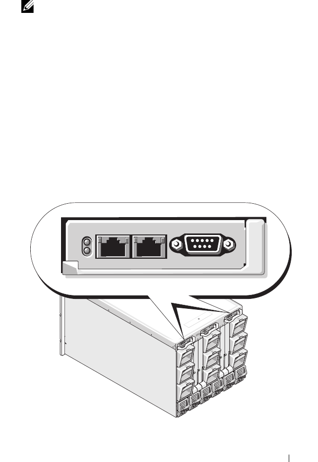
Chassis Overview
Figure 1-1 shows the facing edge of a CMC (inset) and the locations of the
CMC slots in the chassis.
Figure 1-1. Dell M1000e Chassis and CMC

28 CMC Overview
Hardware Specifications
TCP/IP Ports
You must provide port information when opening firewalls for remote access
to a CMC.
Table 1-1 identifies the ports on which the CMC listens for server
connections. Table 1-2 identifies the ports that the CMC uses as clients.
Table 1-1. CMC Server Listening Ports
Port Number Function
22*
SSH
23*
Telnet
80*
HTTP
161
SNMP Agent
443*
HTTPS
* Configurable port
Table 1-2. CMC Client Port
Port Number Function
25
SMTP
53
DNS
68
DHCP-assigned IP address
69
TFTP
162
SNMP trap
636
LDAPS
3269
LDAPS for global catalog (GC)

CMC Overview 29
Supported Remote Access Connections
Table 1-3 lists the connection features.
Supported Platforms
The CMC supports modular systems designed for the M1000e platform. For
information about compatibility with the CMC, see the documentation for
your device.
For the latest supported platforms, see the Dell PowerEdge Compatibility
Guide located on the Dell Support website at support.dell.com.
Supported Web Browsers
Table 1-4 lists the Web browsers supported as CMC clients.
Table 1-3. Supported Remote Access Connections
Connection Features
CMC NIC
• 10Mbps/100Mbps/1Gbps Ethernet via CMC GbE port
• DHCP support
• SNMP traps and email event notification
• Dedicated network interface for the CMC Web interface
• Network interface for the iDRAC and I/O Modules (IOMs)
• Support for Telnet/SSH command console and RACADM CLI
commands including system boot, reset, power-on, and shutdown
commands
Serial port
• Support for serial console and RACADM CLI commands
including system boot, reset, power-on, and shutdown commands
• Support for binary interchange for applications specifically
designed to communicate with a binary protocol to a particular
type of IOM
• Serial port can be switched to IOMs using the
connect
command
Other
connections
• Access to the Dell CMC Console through the Avocent
®
Integrated KVM Switch Module (iKVM)

30 CMC Overview
For the latest information on supported Web browsers, see the Dell
OpenManage Server Administrator Compatibility Guide located on the Dell
Support website at support.dell.com.
To view localized versions of the CMC Web interface:
1
Open the Windows
Control Panel
.
2
Double-click the
Regional Options
icon.
3
Select the desired locale from the
Your locale (location)
drop-down menu.
Supported Management Console Applications
The CMC supports integration with Dell OpenManage IT Assistant. For
more information, refer to the documentation for the OpenManage IT
Assistant.
WS-Management Support
The CMC firmware includes an implementation of the WS-Management
specification. WS-Management, a new Web Services specification over
SOAP-based protocol for systems management, provides a universal language
for devices to share data so they can be managed more easily.
Access to WS-Management requires Administrator (or root) user privileges
using Basic authentication over Secured Socket Layer (SSL) protocol at
port 443. For information on setting user accounts, see
"cfgSessionManagement" on page 397.
Table 1-4. Supported Web Browsers
Operating System Supported Web Browser
Windows®Internet Explorer® 6.0 (32-bit) with Service Pack 2 (SP2) for
Windows XP and Windows 2003 R2 SP2 only.
Internet Explorer 7.0 for Windows Vista®, Windows XP, and
Windows 2003 R2 SP2 only.
Linux Mozilla Firefox 1.5 (32-bit) for SUSE® Enterprise Linux
(version 10) only.
Mozilla Firefox 2.0 (32-bit).

CMC Overview 31
The data available through WS-Management is a subset of data provided by
the CMC instrumentation interface mapped to the following DMTF profiles
version 1.0.0:
• Allocation Capabilities Profile
• Base Metrics Profile
• Base Server Profile
• Computer System Profile
• Modular System Profile
• Physical Asset Profile
• Dell Power Allocation Profile
• Dell Power Supply Profile
• Dell Power Topology Profile
• Power State Management Profile
• Profile Registration Profile
• Record Log Profile
• Resource Allocation Profile
• Role Based Authorization Profile
• Sensors Profile
• Service Processor Profile
• Simple Identity Management Profile
For more information, refer to www.dmtf.org/standards/profiles/. For updates
to this list or information, refer to WS-Management release notes or readme
file.
The WS-Management implementation complies with the DMTF Web
Services for Management (WS Management) specification version 1.0.0.
Known compatible tools that support WS-Management protocol include
(but are not limited to) the Microsoft WinRM and OpenWSMan CLI tools.

32 CMC Overview
For specific WS-Management support, see your management application
documentation. Additional documentation is available on the Web:
• www.wbemsolutions.com/ws_management.html
• DMTF WS-Management Specifications:
www.dmtf.org/standards/wbem/wsman
• DMTF Management Profiles:
www.dmtf.org/standards/profiles
/
Other Documents You May Need
In addition to this User’s Guide, the following documents provide additional
information about the setup and operation of the CMC. All of these
documents may be accessed at http:support.dell.com:
• The CMC online help provides information about using the Web
interface.
•The
Chassis Management Controller (CMC) Secure Digital (SD) Card
Technical Specification
provides minimum BIOS and firmware version,
installation and usage information.
•The
Integrated Dell Remote Access Controller Firmware Version 1.0 User’s
Guide
provides information about installation, configuration and
maintenance of the iDRAC on management and managed systems.
•The
Dell OpenManage™ IT Assistant User’s Guide
provides information
about IT Assistant.
• Documentation specific to your third-party management console
application.
•The
Dell OpenManage Server Administrator’s User’s Guide
provides
information about installing and using Server Administrator.
•The
Dell Update Packages User's Guide
provides information about
obtaining and using Dell Update Packages as part of your system update
strategy.
The following system documents are also available to provide more
information about the system in which your CMC is installed:
•The
Product Information Guide
provides important safety and regulatory
information. Warranty information may be included within this document
or as a separate document.

CMC Overview 33
• The
Rack Installation Guide
and
Rack Installation Instructions
included
with your rack solution describe how to install your system into a rack.
• The
Hardware Owner’s Manual
provides information about system
features and describes how to troubleshoot the system and install or
replace system components.
• Systems management software documentation describes the features,
requirements, installation, and basic operation of the software.
• Documentation for any components you purchased separately provides
information to configure and install these options.
• Updates are sometimes included with the system to describe changes to
the system, software, and/or documentation.
NOTE: Always read the updates first because they often supersede
information in other documents.
• Release notes or readme files may be included to provide last-minute
updates to the system or documentation or advanced technical reference
material intended for experienced users or technicians.
•
For more information on IOM network settings, refer to the Dell™
PowerConnect™ M6220 Switch Important Information document and
the Dell™ PowerConnect™ 6220 Series Port Aggregator White Paper.

34 CMC Overview

Installing and Setting Up the CMC 35
Installing and Setting Up the CMC
This section provides information about how to install your CMC hardware,
establish access to the CMC, and configure your management environment
to use the CMC.
This chapter guides you through the next steps for configuring the CMC:
• Set up initial access to the CMC
• Access the CMC through a network
• Add and configure CMC users
• Update the CMC firmware
Additionally, you can find information about installing and setting up
redundant CMC environments at
"Understanding the Redundant CMC
Environment" on page 55
.
Before You Begin
Prior to setting up your CMC environment, download the latest version of
the CMC firmware from the Dell Support website at support.dell.com.
Then, get the Dell Systems Management Tools and Documentation DVD that
was included with your system:
Installing the CMC Hardware
Because the CMC is preinstalled on your chassis, no installation is required.
To get started with the CMC that is installed on your system, see "Installing
Remote Access Software on a Management Station" on page 36.
You can install a second CMC to run as a standby to the primary CMC. For
more information about a standby CMC, see "Understanding the Redundant
CMC Environment" on page 55.

36 Installing and Setting Up the CMC
Installing Remote Access Software on a
Management Station
You can access the CMC using the Telnet, Secure Shell (SSH), or serial
console utilities provided on your operating system or using the Web
interface.
If you want to use remote RACADM from your management station, you will
need to install it. Your system includes the Dell Systems Management Tools
and Documentation DVD. This DVD includes the following components:
• DVD root - Contains the Dell System Build and Update Utility
• SYSMGMT - Contains the systems management software products
including Dell OpenManage Server Administrator
• Docs - Contains documentation for systems, systems management
software products, peripherals, and RAID controllers
• SERVICE - Contains the tools you need to configure your system, and
delivers the latest diagnostics and Dell-optimized drivers for your system
For information about installing Server Administrator software, see your
Server Administrator User's Guide.
Installing RACADM on a Linux Management Station
1
Log on as root to the system running a supported Red Hat Enterprise
Linux or SUSE Linux Enterprise Server operating system where you want
to install the managed system components.
2
Insert the
Dell Systems Management Tools and Documentation
DVD into
the DVD drive.
3
If necessary, mount the DVD to a location of your choice using the mount
command or a similar command.
NOTE: On the Red Hat Enterprise Linux 5 operating system, DVDs are auto-
mounted with the -noexec mount option. This option does not allow you to run
any executable from the DVD. You need to manually mount the DVD-ROM and then
run the executables.
4
Navigate to the SYSMGMT/srvadmin/linux/supportscripts directory.
Execute the srvadmin-install.sh script as follows:
sh srvadmin-install.sh --express

Installing and Setting Up the CMC 37
or
sh srvadmin-install.sh -x
The script installs the typical software suite for your system configuration.
NOTE: You can log the output of the RPM installation by adding 2>&1 | tee -a
/var/log/srvadmin.log to the above shell script execution. The resulting
command is sh srvadmin-install.sh 2>&1|tee -a
/var/log/srvadmin.log
5
Start the Server Administrator services with the
sh srvadmin-
services.sh
start command.
NOTE: The Dell Systems Management Tools and Documentation DVD contains
version 5.4 of the Dell OpenManage systems management software kit and version
1.0.3 of the Dell Systems Build and Update Utility. The root of the DVD also contains
ISO images of the Dell Systems Build and Update Utility (version 1.0) and the Dell
Systems Console and Agent CD (Dell OpenManage software version 5.3.0.1). You
can also download Web packages of versions 5.4 of the Dell OpenManage Server
Administrator and Dell OpenManage Management Station software from the Dell
Support site at support.dell.com. You can transfer the contents of these Web
packages to CDs or USB keys for systems that do not have DVD drives.
For help with the RACADM command, type racadm help after issuing the
previous commands. For more information about RACADM, see "Using the
RACADM Command Line Interface" on page 69.
NOTE: When using the RACADM remote capability, you must have write
permission on the folders where you are using the RACADM subcommands
involving file operations, for example:
racadm getconfig -f <file name>
or
racadm sslcertupload -t 1 -f c:\cert\cert.txt
Uninstalling RACADM From a Linux Management Station
Open a text console on your management station and type:
rpm -e <
racadm_package_name
>
where
<racadm_package_name>
is the rpm package that was used to
install the RAC software.

38 Installing and Setting Up the CMC
For example, if the rpm package name is srvadmin-racadm5, then type:
rpm -e srvadmin-racadm5
Configuring a Web Browser
You can configure and manage the CMC and the servers and modules
installed in the chassis through a Web browser. See "Supported Web
Browsers" on page 29 for a list of the Web browsers you can use with the
CMC.
Your CMC and the management station where you use your browser must be
on the same network, which is called the management network. Depending on
your security requirements, the management network can be an isolated,
highly secure network.
You must ensure that security measures on the management network, such as
firewalls and proxy servers, do not prevent your Web browser from accessing
the CMC.
Also, be aware that some browser features can interfere with connectivity or
performance, especially if the management network does not have a route to
the Internet. If your management station is running a Windows operating
system, there are Internet Explorer settings that can interfere with
connectivity even when you are using a command line interface to access the
management network.
Proxy Server
If you have a proxy server for browsing and it does not have access to the
management network, you can add the management network addresses to the
browser’s exception list. This instructs the browser to bypass the proxy server
when accessing the management network.
Internet Explorer
Follow these steps to edit the exception list in Internet Explorer:
1
Start Internet Explorer.
2
Click
Tools
→
Internet Options…
, then click
Connections
.
3
In the
Local Area Network (LAN) settings
section, click
LAN Settings….
4
In the
Proxy server
section, click
Advanced….

Installing and Setting Up the CMC 39
5
In the
Exceptions
section, add the addresses for CMCs and iDRACs on
the management network to the semicolon-separated list. You can use
DNS names and wildcards in your entries.
Mozilla FireFox
Follow these steps to edit the exception list in Mozilla FireFox:
1
Start FireFox.
2
Click
Tools
→
Options…
→
Advanced
, then click the
Network
tab.
3
Click
Settings…
.
4
In the
No Proxy for
field, add the addresses for CMCs and iDRACs on the
management network to the comma-separated list. You can use DNS
names and wildcards in your entries.
Microsoft® Phishing Filter
If the Microsoft Phishing Filter is enabled in Internet Explorer 7 on your
management system and your CMC does not have Internet access, you may
experience delays of several seconds when accessing the CMC, whether you
are using the browser or another interface such as remote RACADM. Follow
these steps to disable the phishing filter:
1
Start Internet Explorer.
2
Click
Tools
→
Phishing Filter
, and then click
Phishing Filter Settings
.
3
Check the
Disable Phishing Filter
checkbox.
4
Click
OK
.
Certificate Revocation List (CRL) Fetching
If your CMC has no route to the Internet, you should disable the certificate
revocation list (CRL) fetching feature in Internet Explorer. This feature tests
whether a server such as the CMC Web server is using a certificate that is on
a list of revoked certificates retrieved from the Internet. If the Internet is
inaccessible, this feature can cause delays of several seconds when you access
the CMC using the browser or with a command line interface such as remote
RACADM.

40 Installing and Setting Up the CMC
Follow these steps to disable CRL fetching:
1
Start Internet Explorer.
2
Click
Tools
→
Internet Options…
, then click
Advanced
.
3
Scroll to the Security section and uncheck
Check for publisher’s
certificate revocation
.
4
Click
OK
.
Downloading Files From CMC With Internet Explorer
When you use Internet Explorer to download files from the CMC you may
experience problems when the Do not save encrypted pages to disk option is
not enabled.
Follow these steps to enable the Do not save encrypted pages to disk option:
1
Start Internet Explorer.
2
Click
Tools
→
Internet Options…
, then click
Advanced
.
3
Scroll to the Security section and check
Do not save encrypted pages to
disk
.
Allow Animations in Internet Explorer
When transferring files to and from the Web interface, a file transfer icon
spins to show transfer activity. For Internet Explorer, this requires that the
browser be configured to play animations, which is the default setting.
Follow these steps to configure Internet Explorer to play animations:
1
Start Internet Explorer.
2
Click
Tools
→
Internet Options…
, then click
Advanced
.
3
Scroll to the Multimedia section and check
Play animations in web pages
.
Setting Up Initial Access to the CMC
To manage the CMC remotely, connect the CMC to your management
network and then configure the CMC network settings. For information on
how to configure the CMC network settings, see "Configuring the CMC
Network" on page 44. This initial configuration assigns the TCP/IP
networking parameters that enable access to the CMC.

Installing and Setting Up the CMC 41
The CMC is connected to the management network. All external access to
the CMC and iDRACs is accomplished through the CMC. Access to the
managed servers, conversely, is accomplished through network connections to
I/O modules (IOMs). This allows the application network to be isolated from
the management network.
If you have one chassis, connect the CMC, and the standby CMC if present,
to the management network. If you have more than one chassis, you can
choose between the basic connection, where each CMC is connected to the
management network, or a daisy-chained chassis connection, where the
chassis are connected in series and only one is connected to the management
network. The basic connection type uses more ports on the management
network and provides greater redundancy. The daisy-chain connection type
uses fewer ports on the management network but introduces dependencies
between CMCs, reducing the redundancy of the system.
Basic CMC Network Connection
For the highest degree of redundancy, connect each CMC to your
management network. If a chassis has just one CMC, make one connection
on the management network. If the chassis has a redundant CMC in the
secondary CMC slot, make two connections to the management network.
Each CMC has two RJ-45 Ethernet ports, labeled GB1 (the uplink port) and
STK (the stacking port). With basic cabling, you connect the GB1 port to the
management network and leave the STK port unused.
Daisy-chain CMC Network Connection
If you have multiple chassis in a rack, you can reduce the number of
connections to the management network by daisy-chaining up to four chassis
together. If each of four chassis contains a redundant CMC, by daisy-chaining
you reduce the number of management network connections required from
eight to two. If each chassis has only one CMC, you reduce the connections
required from four to one.
When daisy-chaining chassis together, GB1 is the uplink port and STK is the
stacking port. A GB1 port must connect to the management network or to the
STK port of the CMC in a chassis that is closer to network. The STK port
must only receive a connection from a GB1 port further from the chain or
network.

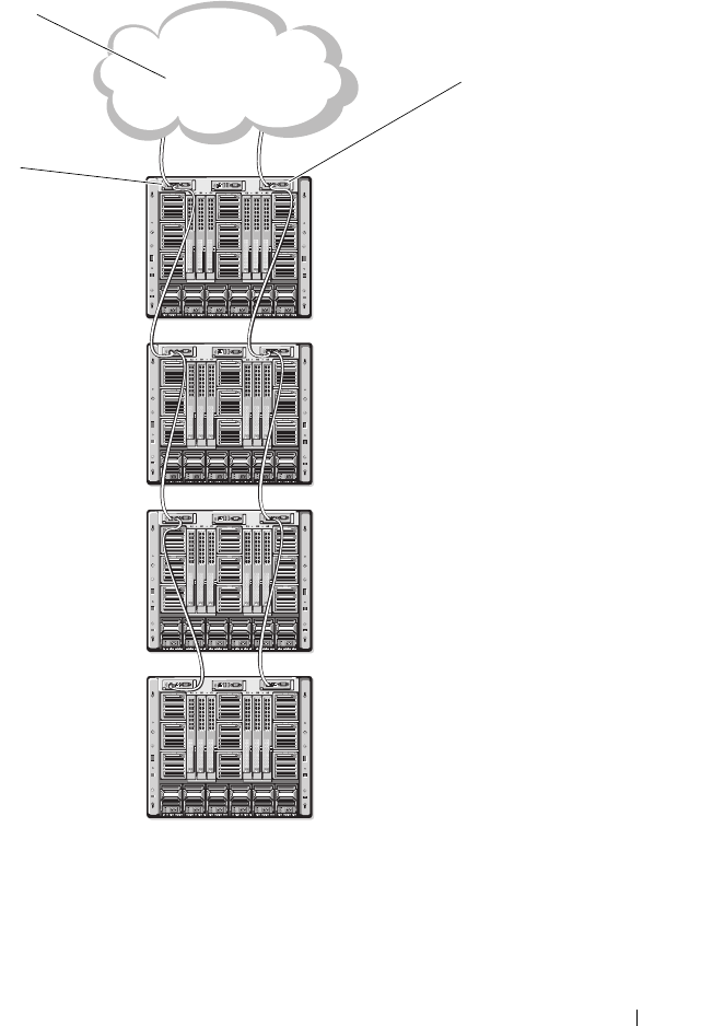
Installing and Setting Up the CMC 43
Figure 2-1. Daisy-chained CMC Network Connection
1 management network 2 secondary CMC
3 primary CMC
1
3
2

44 Installing and Setting Up the CMC
Follow these steps to daisy-chain up to four chassis:
1
Connect the GB1 port of the primary CMC in the first chassis to the
management network.
2
Connect the GB1 port of the primary CMC in the second chassis to the
STK port of the primary CMC in the first chassis.
3
If you have a third chassis, connect the GB1 port of its primary CMC to
the STK port of the primary CMC in the second chassis.
4
If you have a fourth chassis, connect the GB1 port of its primary CMC to
the STK port of the third chassis.
5
If you have redundant CMCs in the chassis, connect them using the same
pattern.
NOTICE: The STK port on any CMC must never be connected to the management
network. It can only be connected to the GB1 port on another chassis. Connecting a
STK port to the management network can disrupt the network and cause a loss of
data.
NOTE: Never connect a primary CMC to a secondary CMC.
NOTE: Resetting a CMC whose STK port is chained to another CMC can disrupt the
network for CMCs later in the chain. The child CMCs may log messages indicating
that the network link has been lost and they may fail over to their redundant CMCs.
Configuring the CMC Network
NOTE: Changing your CMC Network settings may disconnect your current network
connection.
You can perform the initial network configuration of the CMC before or after
the CMC has an IP address. If you configure the CMC’s initial network settings
before you have an IP address, you can use either of the following interfaces:
• The LCD panel on the front of the chassis
• Dell CMC serial console

Installing and Setting Up the CMC 45
If you configure initial network settings after the CMC has an IP address, you
can use any of the following interfaces:
• Command line interfaces (CLIs) such as a serial console, Telnet, SSH, or
the Dell CMC Console via iKVM
• Remote RACADM
• The CMC Web interface
Configuring Networking Using the LCD Configuration Wizard
NOTE: The option to configure the CMC using the LCD Configuration Wizard is
available only until the CMC is deployed or the default password is changed. If the
password is not changed, the LCD can continue to be used to reconfigure the CMC
causing a possible security risk.
The LCD is located on the bottom left corner on the front of the chassis.
Figure 2-2 illustrates the LCD panel.
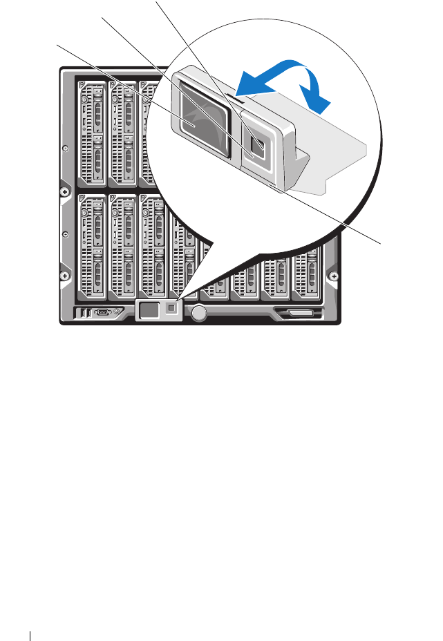
46 Installing and Setting Up the CMC
Figure 2-2. LCD Display
The LCD screen displays menus, icons, pictures, and messages.
A status indicator LED on the LCD panel provides an indication of the
overall health of the chassis and its components.
• Solid blue indicates good health.
• Blinking amber indicates that at least one component has a fault
condition.
• Blinking blue is an ID signal, used to identify one chassis in a group of
chassis.
1 LCD screen 2 scroll buttons (4)
3 selection ("check") button 4 status indicator LED
1
2
3
4

Installing and Setting Up the CMC 47
Navigating in the LCD Screen
The right side of the LCD panel contains five buttons: four arrow buttons
(up, down, left, and right) and a center button.
•
To move between screens
, use the right (next) and left (previous) arrow
buttons. At any time while using the Configuration Wizard, you can
return to a previous screen.
•
To scroll through options on a screen
, use the down and up arrow buttons.
•
To select and save an item on a screen
and move to the next screen, use the
center button.
For more information about using the LCD panel see "Using the LCD Panel
Interface" on page 423.
Using the LCD Configuration Wizard
1
If you have not already done so, press the chassis power button to turn
it on.
The LCD screen displays a series of initialization screens as it powers up.
When it is ready, the
Language Setup
screen displays.
2
Select your language using the down arrow button, and then press the
center button.
The
Enclosure
screen displays with the following question: "Configure
Enclosure?"
3
Press the center button to continue to the
CMC Network Settings
screen.
4
Select your network speed (10Mbps, 100Mbps, 1Gbps, or Auto) using the
down arrow button.
NOTE: The Network Speed setting must match your network configuration for
effective network throughput. Setting the Network Speed lower than the
speed of your network configuration increases bandwidth consumption and
slows network communication. Determine whether your network supports the
above network speeds and set it accordingly. If your network configuration
does not match any of these values, Dell recommends that you use Auto
Negotiation (the Auto option) or refer to your network equipment
manufacturer.
Press the center button to continue to the next
CMC Network Settings
screen.

48 Installing and Setting Up the CMC
5
Select the duplex mode (half or full) that matches your network
environment.
NOTE: The network speed and duplex mode settings are not available if Auto
Negotiation is set to On or 1000MB (1Gbps) is selected.
NOTE: If auto negotiation is turned on for one device but not the other, then
the device using auto negotiation can determine the network speed of the
other device, but not the duplex mode; in this case, duplex mode defaults to
the half duplex setting during auto negotiation. Such a duplex mismatch will
result in a slow network connection.
Press the center button to continue to the next
CMC Network Settings
screen.
6
Select the mode in which you want the CMC to obtain the NIC IP
addresses:
Dynamic Host
Configuration
Protocol (DHCP)
The CMC retrieves IP configuration (IP address, mask, and
gateway) automatically from a DHCP server on your
network. The CMC will be assigned a unique IP address
allotted over your network. If you have selected the DHCP
option, press the center button. The Register DNS? screen
appears; go to step 7.

Installing and Setting Up the CMC 49
7
If you selected Static in the previous step, go to step 8.
To register your DNS server’s IP address, press the center button to
proceed. If you have no DNS, press the right arrow key. The
Configure
iDRAC?
screen appears; go to step 8.
Set the
DNS IP Address
using the right or left arrow keys to move between
positions, and the up and down arrow keys to select a number for each
position. When you have finished setting the DNS IP address, press the
center button to continue.
8
Indicate whether you want to configure iDRAC:
–
No:
Press the right arrow button. The
IP Summary
screen appears.
Skip to step 9.
–
Yes:
Press the center button to proceed.
Static You manually enter the IP address, gateway, and subnet mask
in the screens immediately following.
If you have selected the Static option, press the center
button to continue to the next CMC Network Settings
screen, then:
a
Set the
Static IP Address
by using the right or left arrow
keys to move between positions, and the up and down
arrow keys to select a number for each position. When
you have finished setting the
Static IP Address
, press the
center button to continue.
b
Set the subnet mask, and then press the center button.
c
Set the gateway, and then press the center button. The
Network Summary
screen displays.
The
Network Summary
screen lists the
Static IP
Address
,
Subnet Mask
, and
Gateway
settings you
entered. Review the settings for accuracy. To correct a
setting, navigate to the left arrow button then press the
center key to return to the screen for that setting. After
making a correction, press the center button.
d
When you have confirmed the accuracy of the settings
you entered, press the center button. The
Register DNS?
screen appears.

50 Installing and Setting Up the CMC
NOTE: You cannot set a static IP address for the iDRAC using the LCD
Configuration Wizard. To set a static IP address, use the CMC Web interface
or RACADM.
When you have made your selection, press the center button. The
IP
Summary
screen displays, listing the IP addresses you provided.
9
On the
IP Summary
screen, review the IP addresses you provided to make
sure the addresses are accurate. To correct a setting, navigate to the left
arrow button and then press the center key to return to the screen for that
setting. After making a correction, press the center button. If necessary,
navigate to the right arrow button and then press the center key to return
to the
IP Summary
screen.
When you have confirmed that the settings you entered are accurate, press
the center button. The Configuration Wizard closes and returns you to the
Main Menu
screen.
The CMC is now available on the network. You can access the CMC on the
assigned IP address using the Web interface or CLIs such as a serial console,
Telnet, and SSH.
NOTE: After you have completed network setup through the LCD Configuration
Wizard, the Wizard is no longer available.
Accessing the CMC Through a Network
After you have configured the CMC network settings, you can remotely
access the CMC using any of the following interfaces:
• Web interface
• Telnet console
• SSH
Telnet is enabled via one of the other interfaces; telnet is not as secure as the
other interfaces so it is disabled by default.

Installing and Setting Up the CMC 51
Table 2-1 describes each CMC network interface.
NOTE: The CMC default user name is root and the default password is calvin.
You can access the CMC and iDRAC Web interfaces through the CMC NIC
using a supported Web browser; you can also launch them from the Dell
Server Administrator or Dell OpenManage IT Assistant.
For a list of supported Web browsers, see "Supported Web Browsers" on
page 29. To access the CMC using a supported Web browser, see "Accessing
the CMC Web Interface" on page 93. For information on Dell Server
Administrator and Dell OpenManage IT Assistant, see "Installing Remote
Access Software on a Management Station" on page 36.
Table 2-1. CMC Interfaces
Interface Description
Web interface Provides remote access to the CMC using a graphical user
interface. The Web interface is built into the CMC firmware
and is accessed through the NIC interface from a supported
Web browser on the management station.
For a list of supported Web browsers, see "Supported Web
Browsers" on page 29.
Remote RACADM
command line
interface
Provides remote access to the CMC from a management
station using a command line interface (CLI). Remote
RACADM uses the racadm -r option with the CMC’s IP
address to execute commands on the CMC.
Telnet Provides command line access to the CMC through the
network. The RACADM command line interface and the
connect command, which is used for server and IO module
debugging, are available from the CMC command line.
NOTE: Telnet is an unsecure protocol that transmits all data—
including passwords—in plain text. When transmitting
sensitive information, use the SSH interface.
SSH Provides the same capabilities as Telnet using an encrypted
transport layer for greater security.

52 Installing and Setting Up the CMC
To access the CMC interface using Dell Server Administrator, launch Server
Administrator on your management station. From the system tree on the left
pane of the Server Administrator home page, click System→ Main System
Chassis→ Remote Access Controller. For more information, see your Dell
Server Administrator User’s Guide.
To access the CMC command line using Telnet or SSH, see "Configuring
CMC to Use Command Line Consoles" on page 57.
For information about using RACADM, see "Using the RACADM Command
Line Interface" on page 69.
For information about using the connect command to connect to servers and
IO modules, see "Connecting to Modules With the Connect Command" on
page 67.
Installing or Updating the CMC Firmware
Downloading the CMC Firmware
Before beginning the firmware update, download the latest firmware version
from the Dell Support website at support.dell.com, and save it to your local
system.
The following software components are included with your CMC firmware
package:
• Compiled CMC firmware code and data
• Web interface, JPEG, and other user interface data files
• Default configuration files
NOTE: During updates of CMC firmware, some or all of the fan units in the chassis
will spin at 100%. This is normal.
NOTE: The firmware update, by default, retains the current CMC settings. During
the update process, you have the option to reset the CMC configuration settings
back to the factory default settings.
NOTE: If you have redundant CMCs installed in the chassis, it is important to
update both to the same firmware version. If the CMCs have different firmware and
a failover occurs, unexpected results may occur.

Installing and Setting Up the CMC 53
You can use the RACADM getsysinfo command (see "getsysinfo" on
page 357) or the Chassis Summary page (see "Viewing the Current Firmware
Versions" on page 151) to view the current firmware versions for the CMCs
installed in your chassis.
If you have a standby CMC, it is recommended that you update the firmware
in the standby CMC first. When the standby CMC has been updated, swap
the CMCs’ roles so that the newly updated CMC becomes the primary CMC
and the CMC with the older firmware becomes the standby. (See
"cmcchangeover" on page 321 for help swapping roles.) This allows you to
verify that the update succeeded and that the new firmware is working
properly before you update the firmware in the second CMC. When both
CMCs are updated, you can use the cmcchangeover command to restore the
CMCs to their previous roles.
Updating CMC Firmware Using the Web Interface
For instructions on using the Web interface to update CMC firmware, see
"Updating the CMC Firmware" on page 152.
Updating the CMC Firmware Using RACADM
For instructions on using the RACADM fwupdate subcommand to update
CMC firmware, see "fwupdate" on page 329.
Configuring CMC Properties
You can configure CMC properties such as power budgeting, network
settings, users, and SNMP and email alerts using the Web interface or
RACADM.
For more information about using the Web interface, see "Accessing the
CMC Web Interface" on page 93. For more information about using
RACADM, see "Using the RACADM Command Line Interface" on page 69.
You can configure the CMC using one of the following configuration tools:
• The CMC Web interface. For more information, see "Using the CMC
Web Interface" on page 93.
• A local RACADM command line interface (CLI). Fore more information,
see "Using the RACADM Command Line Interface" on page 69.

54 Installing and Setting Up the CMC
NOTICE: Using more than one CMC configuration tool at the same time may
generate unexpected results.
Configuring Power Budgeting
The CMC offers a power budgeting service that allows you to configure
power budget, redundancy, and dynamic power for the chassis.
The chassis ships with either three or six power supply units (PSUs). If your
chassis has only three PSUs, you can add up to three more. The power
management service enables optimization of power consumption and re-
allocation of power to different modules based on demand.
For more information about CMC power management, see "Power
Management" on page 215.
For instructions on configuring power budgeting and other power settings
using the Web interface, see "Configuring Power Budgeting" on page 150.
Configuring CMC Network Settings
NOTE: Changing your CMC network settings may disconnect your current network
connection.
You can configure the CMC network settings using one of the following tools:
• RACADM — see
"Configuring Multiple CMCs in Multiple Chassis" on
page 84
NOTE: If you are deploying the CMC in a Linux environment, see "Installing
RACADM on a Linux Management Station" on page 36.
• Web interface — see
"Configuring CMC Network Properties" on
page 112
Adding and Configuring Users
You can add and configure CMC users using either RACADM or the CMC
Web interface. You can also utilize Microsoft® Active Directory® to manage
users.
For instructions on adding and configuring users using RACADM, see
"Adding a CMC User" on page 83. For instructions on adding and configuring
users using the Web interface, see "Adding and Configuring CMC Users" on
page 120.

Installing and Setting Up the CMC 55
For instructions on using Active Directory with your CMC, see "Using the
CMC With Microsoft Active Directory" on page 185.
Adding SNMP and Email Alerts
You can configure the CMC to generate SNMP and/or email alerts when
certain chassis events occur. For more information, see "Configuring SNMP
Alerts" on page 286 and "Configuring Email Alerts" on page 291.
Understanding the Redundant CMC Environment
You can install a standby CMC that takes over if your primary CMC fails.
Failovers can occur when you:
• Run the RACADM
cmcchangeover
command. (See "cmcchangeover" on
page 321.)
• Run the RACADM
racreset
command on the active CMC. (See "racreset"
on page 366.)
• Remove the network cable from the active CMC
• Remove the active CMC from the chassis
• Initiate a CMC firmware flash on the active CMC
• Primary CMC is no longer functional
NOTE: In the event of CMC failover, all iDRAC connections and all active CMC
sessions will be lost. Users who lose sessions must reconnect to the new primary
CMC.
About the Standby CMC
The standby CMC is identical to and is maintained as a mirror of the active
CMC. The active and standby CMCs must both be installed with the same
firmware revision. If the firmware revisions differ, the system will report as
redundancy degraded.
The standby CMC assumes the same settings and properties of the primary
CMC. You must maintain the same firmware version on both CMCs, but you
do not need to duplicate configuration settings on the standby CMC.
NOTE: For information about installing a standby CMC, see the Hardware Owner’s
Manual. For instructions on installing the CMC firmware on your standby CMC,
follow the instructions in "Installing or Updating the CMC Firmware" on page 52.

56 Installing and Setting Up the CMC
Primary CMC Election Process
There is no difference between the two CMC slots; that is, slot does not
dictate precedence. Instead, the CMC that is installed or booted first
assumes the role of the active CMC. If AC power is applied with two CMCs
installed, the CMC installed in CMC chassis slot 1 (the left) normally
assumes the active role. The active CMC is indicated by the blue LED.
If two CMCs are inserted into a chassis that is already powered on, automatic
active/standby negotiation can take up to two minutes. Normal chassis
operation resumes when the negotiation is complete.
Planning Deployment of Redundant CMCs
When planning CMC deployment and chassis cabling, it is recommended
that you choose the left CMC to act as the primary and the right CMC to act
as secondary, and then maintain those roles. This is best practice because it is
the default arrangement when the chassis is powered on and redundancy is
increased when all of the primary CMCs in a daisy-chained chassis are cabled
together. When a failover occurs and a CMC in the right slot becomes
primary, use the RACADM cmcchangeover command to reset the CMC in
the left slot to primary.
Obtaining Health Status of Redundant CMC
You can view the health status of the standby CMC in the Web interface. For
more information about accessing CMC health status in the Web interface,
see "Viewing Chassis Graphics and Component Health Status" on page 96.

Configuring CMC to Use Command Line Consoles 57
Configuring CMC to Use Command
Line Consoles
This section provides information about the CMC command line console (or
serial/Telnet/Secure Shell console) features, and explains how to set up your
system so you can perform systems management actions through the console.
For information on using the RACADM commands in CMC via the
command line console, see "Using the RACADM Command Line Interface"
on page 69.
Command Line Console Features on the CMC
The CMC supports the following serial and Telnet console features:
• One serial client connection and up to four simultaneous Telnet client
connections
• Up to four simultaneous Secure Shell (SSH) client connections
• RACADM command support
• Built-in
connect
command for debugging servers and I/O modules
• Command Line editing and history
• Session timeout control on all console interfaces

58 Configuring CMC to Use Command Line Consoles
Using a Serial or Telnet Console
The CMC serial or telnet console enables you to turn on, turn off, or reset the
server and access server logs. When you connect to the CMC command line,
you are able to enter these commands:
Using a Telnet Console With the CMC
Up to four Telnet client systems and four SSH clients may connect at any
given time. The management station connection to the managed system
Telnet console requires management station terminal emulation software. For
more information, see "Configuring Terminal Emulation Software" on
page 60.
Using SSH With the CMC
SSH is a command line session that includes the same capabilities as a Telnet
session, but with session negotiation and encryption to improve security. The
CMC supports SSH version 2 with password authentication. SSH is enabled
on the CMC by default.
NOTE: The CMC does not support SSH version 1.
When an error occurs during the login procedure, the SSH client issues an
error message. The message text is dependent on the client and is not
controlled by the CMC. Review the RACLog messages to determine the
cause of the failure.
Table 3-1. CMC Command Line Commands
Command Description
racadm RACADM commands begin with the keyword racadm and are
followed by a subcommand, such as getconfig, serveraction, or
getsensorinfo. See "Using the RACADM Command Line Interface"
on page 69 for details on using RACADM.
connect Connects to a server or I/O module for debugging. See "Connecting to
Modules With the Connect Command" on page 67 for help using the
connect command.
exit, logout,
and quit
These commands all perform the same action: they end the current
session and return to a login prompt.

Configuring CMC to Use Command Line Consoles 59
NOTE: OpenSSH should be run from a VT100 or ANSI terminal emulator on
Windows. Running OpenSSH at the Windows command prompt does not provide
full functionality (that is, some keys do not respond and no graphics are displayed).
For Linux, run SSH Client Services to connect to CMC with any shell.
Four simultaneous SSH sessions are supported at any given time. The session
timeout is controlled by the cfgSsnMgtSshIdleTimeout property (see
"RACADM Subcommands" on page 317) or from the Services Management
page in the Web interface (see "Configuring Services" on page 143).
Enabling SSH on the CMC
SSH is enabled by default. If SSH is disabled, then you can enable it using
any other supported interface.
For instructions on enabling SSH connections on the CMC using RACADM,
see "config" on page 322 and "cfgSerial" on page 398. For instructions on
enabling SSH connections on the CMC using the Web interface, see
"Configuring Services" on page 143.
Changing the SSH Port
To change the SSH port, use the following command:
racadm config -g cfgRacTuning -o cfgRacTuneSshPort
<port number>
For more information about cfgSerialSshEnable and
cfgRacTuneSshPort properties, see "CMC Property Database Group and
Object Definitions" on page 385.
The CMC SSH implementation supports multiple cryptography schemes, as
shown in Table 3-2.

60 Configuring CMC to Use Command Line Consoles
Enabling the Front Panel to iKVM Connection
For information and instructions on using the iKVM front panel ports, see
"Enabling or Disabling the Front Panel" on page 263.
Configuring Terminal Emulation Software
Your CMC supports a serial or Telnet text console from a management
station running one of the following types of terminal emulation software:
• Linux Minicom in an Xterm
• Hilgraeve’s HyperTerminal Private Edition (version 6.3)
• Linux Telnet or SSH in an Xterm
• Microsoft
®
Telnet
Table 3-2. Cryptography Schemes
Scheme Type Scheme
Asymmetric Cryptography Diffie-Hellman DSA/DSS 512–1024 (random) bits per
NIST specification
Symmetric Cryptography
• AES256-CBC
• RIJNDAEL256-CBC
• AES192-CBC
• RIJNDAEL192-CBC
• AES128-CBC
• RIJNDAEL128-CBC
• BLOWFISH-128-CBC
• 3DES-192-CBC
• ARCFOUR-128
Message Integrity
• HMAC-SHA1-160
• HMAC-SHA1-96
• HMAC-MD5-128
• HMAC-MD5-96
Authentication Password

Configuring CMC to Use Command Line Consoles 61
Perform the steps in the following subsections to configure your type of
terminal software. If you are using Microsoft Telnet, configuration is not
required.
Configuring Linux Minicom for Serial Console Emulation
Minicom is a serial port access utility for Linux. The following steps are valid
for configuring Minicom version 2.0. Other Minicom versions may differ
slightly but require the same basic settings. Use the information in "Required
Minicom Settings for Serial Console Emulation" on page 62 to configure
other versions of Minicom.
Configuring Minicom Version 2.0 for Serial Console Emulation
NOTE: To ensure that the text displays properly, Dell recommends that you use an
Xterm window to display the Telnet console instead of the default console provided
by the Linux installation.
1
To start a new Xterm session, type
xterm &
at the command prompt.
2
In the Xterm window, move your mouse arrow to the lower right-hand
corner of the window and resize the window to 80 x 25.
3
If you do not have a Minicom configuration file, go to the next step.
If you have a Minicom configuration file, type
minicom
<Minicom
config file name>
and skip to step 17.
4
At the Xterm command prompt, type
minicom -s
.
5
Select
Serial Port Setup
and press <Enter>.
6
Press <a>, and then select the appropriate serial device (for example,
/dev/ttyS0
).
7
Press <e>, and then set the
Bps/Par/Bits
option to
115200 8N1
.
8
Press <f>, and then set
Hardware Flow Control
to
Yes
and set
Software
Flow Control
to
No
.
To exit the
Serial Port Setup
menu, press <Enter>.
9
Select
Modem and Dialing
and press <Enter>.
10
In the
Modem Dialing and Parameter Setup
menu, press <Backspace>
to clear the
init
,
reset
,
connect
, and
hangup
settings so that they are blank.
11
Press <Enter> to save each blank value.

62 Configuring CMC to Use Command Line Consoles
12
When all specified fields are clear, press <Enter> to exit the
Modem
Dialing and Parameter Setup
menu.
13
Select
Save setup as config_name
and press <Enter>.
14
Select
Exit From Minicom
and press <Enter>.
15
At the command shell prompt, type
minicom <Minicom config
file name>
.
To expand the Minicom window to 80 x 25, drag the corner of the window.
16
Press <Ctrl+a>, <z>, <x> to exit Minicom.
Ensure that the Minicom window displays a command prompt such as
[iDRAC\root]#. When the command prompt appears, your connection is
successful and you are ready to connect to the managed system console using
the connect serial command.
Required Minicom Settings for Serial Console Emulation
Use Table 3-3 to configure any version of Minicom.
Running Telnet Using Windows XP or Windows 2003
If your management station is running Windows XP or Windows 2003, you
may experience an issue with the characters in a CMC Telnet session. This
issue may occur as a frozen login where the return key does not respond and
the password prompt does not appear.
Table 3-3. Minicom Settings for Serial Console Emulation
Setting Description Required Setting
Bps/Par/Bits 115200 8N1
Hardware flow control Yes
Software flow control No
Terminal emulation ANSI
Modem dialing and
parameter settings
Clear the init, reset, connect, and hangup settings so
that they are blank
Window size 80 x 25 (to resize, drag the corner of the window)

Configuring CMC to Use Command Line Consoles 63
To fix this issue, download hotfix 824810 from the Microsoft Support website
at support.microsoft.com. See Microsoft Knowledge Base article 824810 for
more information.
Configuring Linux for Server Serial Console Redirection During Boot
The following steps are specific to the Linux GRand Unified Bootloader
(GRUB). Similar changes would be necessary for using a different boot loader.
NOTE: When you configure the client VT100 emulation window, set the window or
application that is displaying the redirected console to 25 rows x 80 columns to
ensure proper text display; otherwise, some text screens may be garbled.
Edit the /etc/grub.conf file as follows:
1
Locate the general setting sections in the file and add the following two
new lines:
serial --unit=1 --speed=57600
terminal --timeout=10 serial
2
Append two options to the kernel line:
kernel............. console=ttyS1,57600
3
If the
/etc/grub.conf
contains a
splashimage
directive, comment it out.
The following example shows the changes described in this procedure.
# grub.conf generated by anaconda
#
# Note that you do not have to rerun grub after making
changes
# to this file
# NOTICE: You do not have a /boot partition. This
means that
# all kernel and initrd paths are relative to
/, e.g.
# root (hd0,0)
# kernel /boot/vmlinuz-version ro root=
/dev/sdal
# initrd /boot/initrd-version.img
#
#boot=/dev/sda
default=0

64 Configuring CMC to Use Command Line Consoles
timeout=10
#splashimage=(hd0,2)/grub/splash.xpm.gz
serial --unit=1 --speed=57600
terminal --timeout=10 serial
title Red Hat Linux Advanced Server (2.4.9-e.3smp)
root (hd0,0)
kernel /boot/vmlinuz-2.4.9-e.3smp ro root=
/dev/sda1 hda=ide-scsi console=ttyS0 console=
ttyS1,57600
initrd /boot/initrd-2.4.9-e.3smp.img
title Red Hat Linux Advanced Server-up (2.4.9-e.3)
root (hd0,00)
kernel /boot/vmlinuz-2.4.9-e.3 ro root=/dev/sda1 s
initrd /boot/initrd-2.4.9-e.3.im
When you edit the /etc/grub.conf file, use the following guidelines:
• Disable GRUB's graphical interface and use the text-based interface;
otherwise, the GRUB screen will not be displayed in console redirection.
To disable the graphical interface, comment out the line starting with
splashimage
.
• To start multiple GRUB options to start console sessions through the serial
connection, add the following line to all options:
console=ttyS1,57600
The example
shows
console=ttyS1,57600
added to only the first
option.
Enabling Login to the Server Serial Console After Boot
Edit the file /etc/inittab, as follows:
• Add a new line to configure
agetty
on the COM2 serial port:
co:2345:respawn:/sbin/agetty -h -L 57600 ttyS1
ansi

Configuring CMC to Use Command Line Consoles 65
The following example shows the file with the new line.
#
# inittab This file describes how the INIT process
# should set up the system in a certain
# run-level.
#
# Author: Miquel van Smoorenburg
# Modified for RHS Linux by Marc Ewing and
# Donnie Barnes
#
# Default runlevel. The runlevels used by RHS are:
# 0 - halt (Do NOT set initdefault to this)
# 1 - Single user mode
# 2 - Multiuser, without NFS (The same as 3, if you
# do not have networking)
# 3 - Full multiuser mode
# 4 - unused
# 5 - X11
# 6 - reboot (Do NOT set initdefault to this)
#
id:3:initdefault:
# System initialization.
si::sysinit:/etc/rc.d/rc.sysinit
l0:0:wait:/etc/rc.d/rc 0
l1:1:wait:/etc/rc.d/rc 1
l2:2:wait:/etc/rc.d/rc 2
l3:3:wait:/etc/rc.d/rc 3
l4:4:wait:/etc/rc.d/rc 4
l5:5:wait:/etc/rc.d/rc 5
l6:6:wait:/etc/rc.d/rc 6
# Things to run in every runlevel.
ud::once:/sbin/update
# Trap CTRL-ALT-DELETE
ca::ctrlaltdel:/sbin/shutdown -t3 -r now

66 Configuring CMC to Use Command Line Consoles
# When our UPS tells us power has failed, assume we
have a few
# minutes of power left. Schedule a shutdown for 2
minutes from now.
# This does, of course, assume you have power
installed and your
# UPS is connected and working correctly.
pf::powerfail:/sbin/shutdown -f -h +2 "Power Failure;
System Shutting Down"
# If power was restored before the shutdown kicked in,
cancel it.
pr:12345:powerokwait:/sbin/shutdown -c "Power
Restored; Shutdown Cancelled"
# Run gettys in standard runlevels
co:2345:respawn:/sbin/agetty -h -L 57600 ttyS1 ansi
1:2345:respawn:/sbin/mingetty tty1
2:2345:respawn:/sbin/mingetty tty2
3:2345:respawn:/sbin/mingetty tty3
4:2345:respawn:/sbin/mingetty tty4
5:2345:respawn:/sbin/mingetty tty5
6:2345:respawn:/sbin/mingetty tty6
# Run xdm in runlevel 5
# xdm is now a separate service
x:5:respawn:/etc/X11/prefdm -nodaemon
Edit the file /etc/securetty, as follows:
• Add a new line, with the name of the serial tty for COM2:
ttyS1
The following example shows a sample file with the new line.
vc/1
vc/2
vc/3
vc/4
vc/5
vc/6
vc/7

Configuring CMC to Use Command Line Consoles 67
vc/8
vc/9
vc/10
vc/11
tty1
tty2
tty3
tty4
tty5
tty6
tty7
tty8
tty9
tty10
tty11
ttyS1
Connecting to Modules With the Connect
Command
While in a command line connection, the CMC supports the connect
command to establish a serial connection to server and IOM modules.
Connection to server modules is only provided for operating system
debugging. To connect to server modules to use operating system remote
consoles, you should use the iDRAC Web interface console redirection
feature or the iDRAC Serial Over LAN (SOL) functionality.
NOTICE: When executed from the CMC serial console, the connect -b option stays
connected until the CMC resets. This connection is a potential security risk.
NOTE: The connect command provides the –b (binary) option. The –b option
passes raw binary data, and cfgSerialConsoleQuitKey is not used. Additionally,
when connecting to a server using the CMC serial console, transitions in the DTR
signal (for example, if the serial cable is removed to connect a debugger) do not
cause a logout.
NOTE: If an IOM does not support console redirection, the connect command will
display an empty console. In that case, to return to the CMC console, type the
Escape sequence. The default console escape sequence is <Ctrl>\.
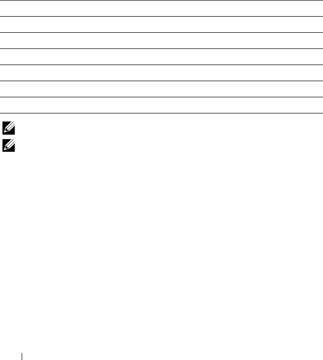
68 Configuring CMC to Use Command Line Consoles
There are up to six IOMs on the managed system. To connect to an IOM,
type:
connect switch-
n
where n is an IOM label a1, a2, b1, b2, c1, and c2.
IOMs are labeled A1, A2, B1, B2, C1, and C2. (See Table 10-1 for an
illustration of the placement of IOMs in the chassis.) When you reference the
IOMs in the connect command, the IOMs are mapped to switches as shown
in Table 3-4.
NOTE: There can only be one IOM connection per chassis at a time.
NOTE: You cannot connect to passthroughs from the serial console.
To connect to a managed server for debugging, use the command connect
server-n, where -n is the slot number of the server you wish to debug. When
you connect to a server, binary communication is assumed and the escape
character is disabled. If the iDRAC is not available, you will see a No route
to host error message. Ensure that your server is inserted properly and the
iDRAC has had time to complete the boot routine.
For details on how to connect through a serial connection, see "Configuring
CMC to Use Command Line Consoles" on page 57.
Table 3-4. Mapping I/O Modules to Switches
I/O Module Label Switch
A1 switch-a1
A2 switch-a2
B1 switch-b1
B2 switch-b2
C1 switch-c1
C2 switch-c2

Using the RACADM Command Line Interface 69
Using the RACADM Command Line
Interface
RACADM provides a set of commands that allow you to configure and
manage the CMC through a text-based interface. RACADM can be accessed
using a Telnet/SSH or serial connection, using the Dell CMC console on the
iKVM, or remotely using the RACADM command line interface installed on
a management station.
The RACADM interface is classified as "local" or "remote," depending on the
location of the racadm executable program you are using:
NOTE: Remote RACADM is included on the Dell Systems Management Tools and
Documentation DVD and is installed on a management station.
• Remote RACADM — you execute RACADM commands on a
management station with the
-r
option and the DNS name or IP address of
the CMC.
• Local RACADM — you log into the CMC using Telnet, SSH, a serial
connection, or the iKVM. With local RACADM, you are executing the
RACADM implementation that is part of the CMC firmware.
You can use remote RACADM commands in scripts to configure multiple
CMCs. The CMC does not have support for scripting, so you cannot execute
scripts directly on the CMC. For more information about configuring
multiple CMCs, see "Configuring Multiple CMCs in Multiple Chassis" on
page 84.
This section provides the following information:
• Using the
serial
and
racadm
commands. See "Using a Serial or Telnet
Console" on page 70 or "Using RACADM" on page 70.
• Configuring your CMC through RACADM. See "Using RACADM to
Configure the CMC" on page 76.
• Using the RACADM configuration file to configure multiple CMCs. See
"Configuring Multiple CMCs in Multiple Chassis" on page 84.

70 Using the RACADM Command Line Interface
Using a Serial or Telnet Console
You can log in to the CMC either through a serial or Telnet/SSH connection,
or through Dell CMC console on iKVM. To configure the CMC for serial or
remote access, see "Configuring CMC to Use Command Line Consoles" on
page 57. Commonly used subcommand options are listed in Table 4-2. A
complete list of RACADM subcommands is listed in "RACADM
Subcommands" on page 317.
Logging in to the CMC
After you have configured your management station terminal emulator
software and managed node BIOS, perform the following steps to log into the
CMC:
1
Connect to the CMC using your management station terminal emulation
software.
2
Type your CMC user name and password, and then press <Enter>.
You are logged into the CMC.
Starting a Text Console
You can log in to the CMC using Telnet or SSH through a network, serial
port, or a Dell CMC console through the iKVM. Open a Telnet or SSH
session, connect and log on to the CMC.
For information about connecting to the CMC through iKVM, see "Using the
iKVM Module" on page 245.
Using RACADM
RACADM subcommands can be run remotely from the serial or Telnet
console command prompt or through a normal command prompt.
Use RACADM subcommands to configure CMC properties and perform
remote management tasks. To display a list of RACADM subcommands, type:
racadm help

Using the RACADM Command Line Interface 71
When run without options or subcommands, RACADM displays syntax
information and instructions on how to access subcommands and help. To
list syntax and command-line options for individual subcommands, type:
racadm help
<subcommand>
RACADM Subcommands
Table 4-1 provides a brief list of common subcommands used in RACADM.
For a complete list of RACADM subcommands, including syntax and valid
entries, see "RACADM Subcommands" on page 317.
NOTE: The connect, exit, quit, and logout commands are built-in CMC commands,
not RACADM commands. They cannot be used with remote RACADM. See
"Connecting to Modules With the Connect Command" on page 67 for information
about using these commands.
When entering a RACADM subcommand, prefix the command with
racadm. For example:
racadm help
Table 4-1. RACADM Subcommands
Command Description
help Lists CMC subcommand descriptions.
help <subcommand> Lists usage summary for the specified subcommand.
? Lists CMC subcommand descriptions.
? <subcommand> Lists usage summary for the specified subcommand.
arp Displays the contents of the ARP table. ARP table entries
may not be added or deleted.
chassisaction Executes power-up, power-down, reset, and power-cycle on
the chassis, switch, and KVM.
clrraclog Clears the CMC log and creates a single entry indicating
the user and time that the log was cleared.
clrsel Clears the System Event Log entries.
cmcchangeover Changes the state of the CMC from active to standby, or
vice versa, in redundant CMC environments.
config Configures the CMC.

72 Using the RACADM Command Line Interface
deploy Deploys a server by specifying required properties.
feature Displays active features and feature deactivation.
featurecard Displays feature card status information.
fwupdate Performs system component firmware updates, and
displays firmware update status.
getassettag Displays the asset tag for the chassis.
getchassisname Displays the name of the chassis.
getconfig Displays the current CMC configuration properties.
getdcinfo Displays general I/O module and daughter card
misconfiguration information.
getflexaddr Displays the FlexAddress enabled/disabled status on a per
slot/fabric basis. If used with the -i option, the command
displays the WWN and MAC address for a particular slot.
getioinfo Displays general I/O module information.
getkvminfo Displays information about the iKVM.
getled Displays the LED settings on a module.
getmacaddress Displays a server’s MAC address.
getmodinfo Displays module configuration and status information.
getniccfg Displays the current IP configuration for the controller.
getpbinfo Displays power budget status information.
getraclog Displays the CMC log.
getractime Displays the CMC time.
getredundancymode Displays the redundancy mode of the CMC.
getsel Displays the system event log (hardware log).
getsensorinfo Displays information about system sensors.
getslotname Displays the name of a slot in the chassis.
getssninfo Displays information about active sessions.
getsvctag Displays service tags.
Table 4-1. RACADM Subcommands (continued)
Command Description

Using the RACADM Command Line Interface 73
getsysinfo Displays general CMC and system information.
gettracelog (Dell internal
use only)
Displays the CMCtrace log. If used with the -i option,
the command displays the number of entries in the CMC
trace log.
ifconfig Displays the current CMC IP configuration.
netstat Displays the routing table and the current connections.
ping Verifies that the destination IP address is reachable from
the CMC with the current routing-table contents.
racdump Displays the comprehensive chassis status and
configuration state information, as well as historic event
logs. Used for post deployment configuration verification
and during debugging sessions.
racreset Resets the CMC.
racresetcfg Resets the CMC to the default configuration.
serveraction Performs power management operations on the managed
system.
setassettag Sets the asset tag for the chassis.
setchassisname Sets the name of the chassis.
setflexaddr Enables/disables FlexAddress on a particular slot/fabric,
when the FlexAddress feature is activated on the chassis
setled Sets the LED settings on a module.
setniccfg Sets the IP configuration for the controller.
setractime Sets the CMC time.
setslotname Sets the name of a slot in the chassis.
setsysinfo Sets the name and location of the chassis.
sslcertdownload Downloads a certificate authority-signed certificate.
sslcertupload Uploads a certificate authority-signed certificate or server
certificate to the CMC.
sslcertview Views a certificate authority-signed certificate or server
certificate in the CMC.
Table 4-1. RACADM Subcommands (continued)
Command Description

74 Using the RACADM Command Line Interface
Accessing RACADM Remotely
Table 4-2 lists the options for the remote RACADM subcommands.
To access RACADM remotely, type the following commands:
racadm -r
<CMC IP address>
-u
<username>
-p
<password>
<subcommand>
<subcommand options>
racadm -i -r
<CMC IP address> <subcommand> <subcommand
options>
sslcsrgen Generates and downloads the SSL CSR.
sslresetcfg Regenerates the self-signed certificate used by the CMC
Web GUI.
testemail Forces the CMC to send an email over the CMC NIC.
testtrap Forces the CMC to send an SNMP over the CMC NIC.
Table 4-2. Remote RACADM Subcommand Options
Option Description
-r <
racIpAddr
>
-r <
racIpAddr
>:<
port
>
Specifies the controller’s remote IP
address.
Use <port number> if the CMC port
number is not the default port (443)
-i Instructs RACADM to interactively query
the user for user name and password.
-u <
usrName
>Specifies the user name that is used to
authenticate the command transaction. If
the -u option is used, the -p option must
be used, and the -i option (interactive) is
not allowed.
-p <
password
>Specifies the password used to
authenticate the command transaction. If
the -p option is used, the -i option is not
allowed.
Table 4-1. RACADM Subcommands (continued)
Command Description

Using the RACADM Command Line Interface 75
NOTE: The -i option instructs RACADM to interactively prompt for user name and
password. Without the -i option, you must provide the user name and password in
the command using the -u and -p options.
For example:
racadm -r 192.168.0.120 -u root -p calvin getsysinfo
racadm -i -r 192.168.0.120 getsysinfo
If the HTTPS port number of the CMC has been changed to a custom port
other than the default port (443), the following syntax must be used:
racadm -r
<CMC IP address>:<port> -u <username> -p
<password> <subcommand> <subcommand options>
racadm -i -r
<CMC IP address>:<port> <subcommand>
<subcommand options>
Enabling and Disabling the RACADM Remote Capability
NOTE: Dell recommends that you run these commands at the chassis.
The RACADM remote capability on the CMC is enabled by default. In the
following commands, -g specifies the configuration group the object belongs
to, and -o specifies the configuration object to configure.
To disable the RACADM remote capability, type:
racadm config -g cfgRacTuning -o
cfgRacTuneRemoteRacadmEnable 0
To re-enable RACADM remote capability, type:
racadm config -g cfgRacTuning -o
cfgRacTuneRemoteRacadmEnable 1
Using RACADM Remotely
NOTE: Configure the IP address on your CMC before using the RACADM remote
capability. For more information about setting up your CMC, see "Installing and
Setting Up the CMC" on page 35.
The RACADM console’s remote option (-r) allows you to connect to the
managed system and execute RACADM subcommands from a remote
console or management station. To use the remote capability, you need a
valid user name (-u option) and password (-p option), and the CMC IP
address.

76 Using the RACADM Command Line Interface
Before you try to access RACADM remotely, confirm that you have
permissions to do so. To display your user privileges, type:
racadm getconfig -g cfguseradmin -i
n
where n is your user ID (1–16).
If you do not know your user ID, try different values for n.
NOTE: The RACADM remote capability is supported only on management stations
through a supported browser. See "Supported Web Browsers" on page 29 for more
information.
NOTE: When using the RACADM remote capability, you must have write
permissions on the folders where you are using the RACADM subcommands
involving file operations. For example:
racadm getconfig -f <
file name
> -r <IP address>
or
racadm sslcertupload -t 1 -f c:\cert\cert.txt
RACADM Error Messages
For information about RACADM CLI error messages, see "Troubleshooting"
on page 90.
Using RACADM to Configure the CMC
NOTE: In order to configure CMC the first time. You must be logged in as user root
to execute RACADM commands on a remote system. Another user can be created
that will give him or her the permission to configure the CMC.
The CMC Web interface is the quickest way to configure the CMC (see
"Using the CMC Web Interface" on page 93). However, if you prefer CLI or
script configuration or need to configure multiple CMCs, use RACADM,
which is installed with the CMC agents on the management station.

Using the RACADM Command Line Interface 77
Configuring CMC Network Properties
Setting Up Initial Access to the CMC
Before you can begin configuring the CMC, you must first configure the
CMC network settings to allow the CMC to be managed remotely. This
initial configuration assigns the TCP/IP networking parameters that enable
access to the CMC.
This section explains how to perform the initial CMC network configuration
using RACADM commands. All of the configuration described in this section
can be performed using the front panel LCD. See "Configuring Networking
Using the LCD Configuration Wizard" on page 45.
NOTICE: Changing your CMC Network settings may disconnect your current
network connection.
For more information about network subcommands, see "RACADM
Subcommands" on page 317 and "CMC Property Database Group and Object
Definitions" on page 385.
NOTE: You must have Chassis Configuration Administrator privilege to set up CMC
network settings.
By default, the CMC requests and obtains a CMC IP address from the
Dynamic Host Configuration Protocol (DHCP) server automatically.
You can disable this feature and specify static CMC IP address, gateway, and
subnet mask.
To disable DHCP and specify static CMC IP address, gateway, and subnet
mask, type:
racadm config -g cfgLanNetworking -o cfgNicUseDHCP 0
racadm config -g cfgLanNetworking -o cfgNicIpAddress
<
static IP address
>
racadm config -g cfgLanNetworking -o cfgNicGateway
<
static gateway
>
racadm config -g cfgLanNetworking -o cfgNicNetmask
<
static subnet mask
>

78 Using the RACADM Command Line Interface
Viewing Current Network Settings
To view a summary of NIC, DHCP, network speed, and duplex settings, type:
racadm getniccfg
or
racadm getconfig -g cfgCurrentLanNetworking
To view IP address and DHCP, MAC address, and DNS information for the
chassis, type:
racadm getsysinfo
Configuring the Network LAN Settings
NOTE: To perform the following steps, you must have Chassis Configuration
Administrator privilege.
NOTE: The LAN settings, such as community string and SMTP server IP address,
affect both the CMC and the external settings of the chassis.
NOTE: If you have two CMCs (primary and standby) on the chassis, and they are
both connected to the network, the standby CMC automatically assumes the
network settings in the event of failover of the primary CMC.
Enabling the CMC NIC
To enable the CMC NIC, type:
racadm config -g cfgLanNetworking -o cfgNicEnable 1
NOTE: The CMC NIC is enabled by default.
Enabling or Disabling DCHP for the NIC Address
When enabled, the CMC’s DHCP for NIC address feature requests and
obtains an IP address from the Dynamic Host Configuration Protocol
(DHCP) server automatically. This feature is enabled by default.
You can disable the DHCP for NIC address feature and specify a static IP
address, subnet mask, and gateway. For instructions, see "Setting Up Initial
Access to the CMC" on page 77.
NOTE: If you disable the DHCP for NIC address feature and then re-enable it later,
the static IP address, subnet mask, and gateway settings are lost.

Using the RACADM Command Line Interface 79
Enabling or Disabling DHCP for DNS IP Addresses
By default, the CMC’s DHCP for DNS address feature is disabled. When
enabled, this feature obtains the primary and secondary DNS server addresses
from the DHCP server. Using this feature, you do not have to configure static
DNS server IP addresses.
To disable the DHCP for DNS address feature and specify static preferred and
alternate DNS server addresses, type:
racadm config -g cfgLanNetworking -o
cfgDNSServersFromDHCP
Setting Static DNS IP addresses
NOTE: These settings are not valid unless the DCHP for DNS address feature is
disabled.
To set the preferred DNS IP address, type:
racadm config -g cfgLanNetworking -o cfgDNSServer1
<
IP-address
>
To set the secondary DNS IP address, type:
racadm config -g cfgLanNetworking -o cfgDNSServer2
<IP-address>
Configuring DNS Settings
•
CMC Registration.
To register the CMC on the DNS server, type:
racadm config -g cfgLanNetworking -o
cfgDNSRegisterRac 1
NOTE: Some DNS servers will only register names of 31 characters or fewer.
Make sure the designated name is within the DNS required limit.
NOTE: The following settings are valid only if you have registered the CMC on
the DNS server by setting cfgDNSRegisterRac to 1.
•
CMC Name.
By default, the CMC name on the DNS server is cmc-
<service tag>. To change the CMC name on the DNS server, type:
racadm config -g cfgLanNetworking -o cfgDNSRacName
<
name
>

80 Using the RACADM Command Line Interface
where <
name
> is a string of up to 63 alphanumeric characters and
hyphens; the name must begin with a letter. For example, cmc-1, d-345.
•
DNS Domain Name.
The default DNS domain name is a single blank
character. To set a DNS domain name, type:
racadm config -g cfgLanNetworking -o
cfgDNSDomainName <
name
>
where <
name
> is a string of up to 254 alphanumeric characters and
hyphens; the DNS domain name must begin with a letter. For example:
p45, a-tz-1, r-id-001.
Configuring Auto Negotiation, Duplex Mode, and Network Speed
When enabled, the auto negotiation feature determines whether the CMC
automatically sets the duplex mode and network speed by communicating
with the nearest router or switch. Auto negotiation is enabled by default.
You can disable auto negotiation and specify the duplex mode and network
speed by typing:
racadm config -g cfgNetTuning -o cfgNetTuningNicEnable 0
racadm config -g cfgNetTuning -o cfgNetTuningNicFullDuplex <duplex
mode> where:
•<
duplex mode
> is 0 (half duplex) or 1 (full duplex, default)
racadm config -g cfgNetTuning -o cfgNetTuningNicSpeed <speed>
where:
•<
speed
> is 10 or 100(default).
Setting the Maximum Transmission Unit (MTU)
The MTU property allows you to set a limit for the largest packet that can be
passed through the interface. To set the MTU, type:
racadm config -g cfgNetTuning -o cfgNetTuningMtu <
mtu
>
where <
mtu
> is a value between 576–1500 (inclusive; default is 1500).

Using the RACADM Command Line Interface 81
Setting the SMTP Server IP Address
You can enable the CMC to send email alerts using Simple Mail Transfer
Protocol (SMTP) to a specified IP address. To enable this feature, type:
racadm config -g cfgRemoteHosts -o
cfgRhostsFwUpdateIpAddr <
SMTP IP address
>
where <
SMTP IP address
> is the IP address of the network SMTP server.
NOTE: If your network has an SMTP server that releases and renews IP address
leases periodically, and the addresses are different, then there will be a duration
when this property setting will not work due to change in the specified SMTP server
IP address. In such cases, use the DNS name.
Configuring the Network Security Settings
NOTE: To perform the following steps, you must have Chassis Configuration
Administrator privilege.
Enabling IP Range Checking
IP filtering compares the IP address of an incoming login to the IP address
range that is specified in the following cfgRacTuning properties:
• cfgRacTuneIpRangeAddr
• cfgRacTuneIpRangeMask
The cfgRacTuneIpRangeMask property is applied to both the incoming IP
address and to the cfgRacTuneIpRangeAddr properties. If the results are
identical, the incoming login request is allowed to access the iDRAC. Logins
from IP addresses outside this range receive an error.
The login proceeds only if either the cfgRacTuneIpRangeMask is zero or the
incoming IP address is identical to the IP address specified by
cfgRacTuneIpRangeAddr.

82 Using the RACADM Command Line Interface
Using RACADM to Configure Users
Before You Begin
You can configure up to 16 users in the CMC property database. Before you
manually enable a CMC user, verify if any current users exist. If you are
configuring a new CMC or you ran the RACADM racresetcfg command,
the only current user is root with the password calvin. The
racresetcfg subcommand resets the CMC back to the original defaults.
NOTICE: Use caution when using the racresetcfg command, because it will
reset all configuration parameters to the original defaults. Any previous changes
are lost.
NOTE: Users can be enabled and disabled over time, and disabling a user does not
delete the user from the database. If a user is disabled and then added again, the
user may have a different index number on each chassis.
To verify if a user exists, open a Telnet/SSH text console to the CMC, log in,
and type:
racadm getconfig -u <
username
>
or
type the following command once for each index of 1–16:
racadm getconfig -g cfgUserAdmin -i <
index
>
NOTE: You can also type racadm getconfig -f <
myfile.cfg
> to view or
edit the
myfile.cfg
file, which includes all CMC configuration parameters.
Several parameters and object IDs are displayed with their current values.
Two objects of interest are:
# cfgUserAdminIndex=XX
cfgUserAdminUserName=
If the cfgUserAdminUserName object has no value, that index number,
which is indicated by the cfgUserAdminIndex object, is available for use.
If a name appears after the "=," that index is taken by that user name.
NOTE: When you manually enable or disable a user with the RACADM config
subcommand, you must specify the index with the -i option. Observe that the
cfgUserAdminIndex object displayed in the previous example contains a #
character. Also, if you use the racadm config -f racadm.cfg command to

Using the RACADM Command Line Interface 83
specify any number of groups/objects to write, the index cannot be specified. A
new user is added to the first
available index. This behavior allows more flexibility in
configuring a second CMC with the same settings as the main CMC.
Adding a CMC User
To add a new user to the CMC configuration, you can use a few basic
commands. Perform the following procedures:
1
Set the user name.
2
Set the password.
3
Set the user privileges. For information about user privileges, see Table 5-9,
Table 5-10, and Table B-1.
4
Enable the user.
Example
The following example describes how to add a new user named "John" with a
"123456" password and LOGIN privilege to the CMC.
NOTE: See Table B-1 for a list of valid bit mask values for specific user privileges.
The default privilege value is 0, which indicates the user has no privileges enabled.
racadm config -g cfgUserAdmin -o cfgUserAdminUserName
-i 2 john
racadm config -g cfgUserAdmin -o cfgUserAdminPassword
-i 2 123456
racadm config -g cfgUserAdmin -i 2 -o
cfgUserAdminPrivilege 0x00000001
racadm config -g cfgUserAdmin -i 2 -o
cfgUserAdminEnable 1
To verify that the user was added successfully with the correct privileges, use
one of the following commands:
racadm getconfig -u john
or
racadm getconfig –g cfgUserAdmin –i 2

84 Using the RACADM Command Line Interface
Enabling a CMC User With Permissions
To enable a user with specific administrative permissions (role-based
authority), first locate an available user index by performing the steps in
"Before You Begin" on page 82. Next, type the following command lines with
the new user name and password.
NOTE: See Table B-1 for a list of valid bit mask values for specific user privileges.
The default privilege value is 0, which indicates the user has no privileges enabled.
racadm config -g cfgUserAdmin -o
cfgUserAdminPrivilege -i <index> <user privilege bitmask value>
Disabling a CMC User
Using RACADM, you can only disable CMC users manually and on an
individual basis. You cannot delete users by using a configuration file.
The following example illustrates the command syntax that can be used to
delete a CMC user:
racadm config -g cfgUserAdmin -i 2
cfgUserAdminPrivilege 0x0
Configuring SNMP and Email Alerting
You can configure the CMC to send SNMP event traps and/or email alerts
when certain events occur on the chassis. For more information and
instructions, see "Configuring SNMP Alerts" on page 286 and "Configuring
Email Alerts" on page 291.
Configuring Multiple CMCs in Multiple Chassis
Using RACADM, you can configure one or more CMCs with identical
properties.
When you query a specific CMC card using its group ID and object ID,
RACADM creates the racadm.cfg configuration file from the retrieved
information. By exporting the file to one or more CMCs, you can configure
your controllers with identical properties in a minimal amount of time.
NOTE: Some configuration files contain unique CMC information (such as the static
IP address) that must be modified before you export the file to other CMCs.

Using the RACADM Command Line Interface 85
1
Use RACADM to query the target CMC that contains the desired
configuration.
NOTE: The generated configuration file is myfile.cfg. You can rename the file.
NOTE: The .cfg file does not contain user passwords. When the .cfg file is
uploaded to the new CMC, you must re-add all passwords.
Open a Telnet/SSH text console to the CMC, log in, and type:
racadm getconfig -f myfile.cfg
NOTE: Redirecting the CMC configuration to a file using getconfig -f is only
supported with the remote RACADM interface.
2
Modify the configuration file using a plain-text editor (optional). Any
special formatting characters in the configuration file may corrupt the
RACADM database.
3
Use the newly created configuration file to modify a target CMC.
At the command prompt, type:
racadm config -f myfile.cfg
4
Reset the target CMC that was configured. At the command prompt, type:
racadm reset
The getconfig -f myfile.cfg subcommand (step 1) requests the CMC
configuration for the primary CMC and generates the myfile.cfg file. If
required, you can rename the file or save it to a different location.
You can use the getconfig command to perform the following actions:
• Display all configuration properties in a group (specified by group name
and index)
• Display all configuration properties for a user by user name
The config subcommand loads the information into other CMCs. The Server
Administrator uses the config command to synchronize the user and
password database.

86 Using the RACADM Command Line Interface
Creating a CMC Configuration File
The CMC configuration file, <filename>.cfg, is used with the racadm
config -f <filename>.cfg command to create a simple text file. The
command allows you to build a configuration file (similar to an .ini file) and
configure the CMC from this file.
You may use any file name, and the file does not require a .cfg extension
(although it is referred to by that designation in this subsection).
NOTE: For more information about the getconfig subcommand, see "getconfig" on
page 332.
RACADM parses the .cfg when it is first loaded onto the CMC to verify that
valid group and object names are present and that some simple syntax rules
are being followed. Errors are flagged with the line number that detected the
error, and a message explains the problem. The entire file is parsed for
correctness, and all errors display. Write commands are not transmitted to the
CMC if an error is found in the .cfg file. You must correct all errors before any
configuration can take place.
To check for errors before you create the configuration file, use the -c option
with the config subcommand. With the -c option, config only verifies syntax
and does not write to the CMC.
Use the following guidelines when you create a .cfg file:
• If the parser encounters an indexed group, it is the value of the anchored
object that differentiates the various indexes.
The parser reads in all of the indexes from the CMC for that group. Any
objects within that group are modifications when the CMC is configured.
If a modified object represents a new index, the index is created on the
CMC during configuration.
• You cannot specify a desired index in a
.cfg
file.
Indexes may be created and deleted. Over time the group may become
fragmented with used and unused indexes. If an index is present, it is
modified. If an index is not present, the first available index is used. This
method allows flexibility when adding indexed entries where you do not
need to make exact index matches between all the CMCs being managed.
New users are added to the first available index. A
.cfg
file that parses and
runs correctly on one CMC may not run correctly on another if all indexes
are full and you must add a new user.

Using the RACADM Command Line Interface 87
• Use the
racresetcfg
subcommand to configure both CMCs with
identical properties.
Use the
racresetcfg
subcommand to reset the CMC to original
defaults, and then run the
racadm config -f <filename>.cfg
command. Ensure that the
.cfg
file includes all desired objects, users,
indexes, and other parameters. See
"CMC Property Database Group and
Object Definitions" on page 385
for a complete list of objects and groups.
NOTICE: Use the racresetcfg subcommand to reset the database and the
CMC NIC settings to the original default settings and remove all users and user
configurations. While the root user is available, other users’ settings are also reset
to the default settings.
Parsing Rules
• Lines that start with a hash character (#) are treated as comments.
A comment line
must
start in column one. A "#" character in any other
column is treated as a # character.
Some modem parameters may include # characters in their strings. An
escape character is not required. You may want to generate a
.cfg
from a
racadm getconfig -f
<filename>
.cfg
command, and then
perform a
racadm config -f
<filename>
.cfg
command to a
different CMC, without adding escape characters.
Example:
#
# This is a comment
[cfgUserAdmin]
cfgUserAdminPageModemInitString=<Modem init # not
a comment>
• All group entries must be surrounded by open- and close-brackets
([ and ]
)
.
The starting [ character that denotes a group name
must
be in column
one. This group name
must
be specified before any of the objects in that
group. Objects that do not include an associated group name generate an
error. The configuration data is organized into groups as defined in
"CMC
Property Database Group and Object Definitions" on page 385
.

88 Using the RACADM Command Line Interface
The following example displays a group name, object, and the object’s
property value:
[cfgLanNetworking] -{
group name
}
cfgNicIpAddress=143.154.133.121 {
object name
}
{
object value
}
• All parameters are specified as "object=value" pairs with no white space
between the object, =, or value.
White spaces that are included after the value are ignored. A white space
inside a value string remains unmodified. Any character to the right of the
= (for example, a second =, a #, [, ], and so on) is taken as-is. These
characters are valid modem chat script characters.
[cfgLanNetworking] -{
group name
}
cfgNicIpAddress=143.154.133.121 {
object value}
•The
.cfg
parser ignores an index object entry.
Yo u
cannot
specify which index is used. If the index already exists, it is
either used or the new entry is created in the first available index for that
group.
The
racadm getconfig -f
<filename>
.cfg
command places a
comment in front of index objects, allowing you to see the included
comments.
NOTE: You may create an indexed group manually using the following
command:
racadm config -g <groupName> -o <anchored
object> -i <index 1–16> <unique anchor name>
• The line for an indexed group
cannot
be deleted from a
.cfg
file. If you do
delete the line with a text editor, RACADM will stop when it parses the
configuration file and alert you of the error.
You must remove an indexed object manually using the following
command:
racadm config -g <
groupName
> -o <
objectName
> -i
<
index 1–16
> ""
NOTE: A NULL string (identified by two "
characters) directs the CMC to
delete the index for the specified group.

Using the RACADM Command Line Interface 89
To view the contents of an indexed group, use the following command:
racadm getconfig -g <
groupName
> -i <
index 1–16
>
• For indexed groups the object anchor
must
be the first object after the [ ]
pair. The following are examples of the current indexed groups:
[cfgUserAdmin]
cfgUserAdminUserName=<
USER_NAME
>
If you type
racadm getconfig -f <
myexample
>.cfg
, the
command builds a
.cfg
file for the current CMC configuration. This
configuration file can be used as an example and as a starting point for
your unique
.cfg
file.
Modifying the CMC IP Address
When you modify the CMC IP address in the configuration file, remove all
unnecessary <
variable
>=
<value>
entries. Only the actual variable
group’s label with [ and ] remains, including the two <
variable
>=
<value>
entries pertaining to the IP address change.
Example:
#
# Object Group "cfgLanNetworking"
#
[cfgLanNetworking]
cfgNicIpAddress=10.35.10.110
cfgNicGateway=10.35.10.1
This file will be updated as follows:
#
# Object Group "cfgLanNetworking"
#
[cfgLanNetworking]
cfgNicIpAddress=10.35.9.143

90 Using the RACADM Command Line Interface
# comment, the rest of this line is ignored
cfgNicGateway=10.35.9.1
The command racadm config -f <
myfile
>.cfg parses the file and
identifies any errors by line number. A correct file will update the proper
entries. Additionally, you can use the same getconfig command from the
previous example to confirm the update.
Use this file to download company-wide changes or to configure new systems
over the network with the command, racadm getconfig -f
<
myfile
>.cfg.
NOTE: "Anchor" is a reserved word and should not be used in the .cfg file.
Troubleshooting
Table 4-3 lists common problems related to remote RACADM.
Table 4-3. Using the Serial and RACADM Commands: Frequently
Asked Questions
Question Answer
After performing a CMC reset (using the
RACADM racreset subcommand), I issue
a command and the following message is
displayed:
racadm
<subcommand>
Transport: ERROR: (RC=-1)
What does this message mean?
You must wait until the CMC completes
the reset before issuing another
command.

Using the RACADM Command Line Interface 91
Command updates for CMC 1.20
The following commands have been updated for the CMC 1.20 release:
• chassisaction
–
-d
and
-w
deprecated
–
nongraceshutdown
added
When I use the RACADM
subcommands, I get errors that I do not
understand.
You may encounter one or more of the
following errors when using RACADM:
• Local error messages — Problems such
as syntax, typographical errors, and
incorrect names.
Example:
ERROR: <message>
Use the RACADM
help
subcommand
to display correct syntax and usage
information.
• CMC-related error messages —
Problems where the CMC is unable to
perform an action. Also might say
"racadm command failed."
Ty p e
racadm gettracelog
for debugging
information.
While I was using remote RACADM, the
prompt changed to a ">" and I cannot get
the "$" prompt to return.
If you type a double quotation mark (") in
the command, the CLI will change to the
">" prompt and queue all commands.
To return to the "$" prompt, type
<Ctrl>–d.
I tried using the following commands and
received an error saying "Not Found":
$ logout
$ quit
The logout and quit commands are not
supported in the CMC CLI interface.
Table 4-3. Using the Serial and RACADM Commands: Frequently
Asked Questions (continued)
Question Answer

92 Using the RACADM Command Line Interface
• gettracelog/gettraclog/getsel
–
-A
and
-o
do not generate additional output; provide backwards
compatibility for existing scripts
• getsensorinfo
–
-s
and
-G
deprecated
• serveraction
–
-s
is now
-m
to specify a server
–
-A
applies the serveraction command to all servers in the enclosure
–
graceshutdown
deprecated
•fwupdate
– added
{-f <ftp server ip address> <username> <password>}
to
specify FTP server IP address and username and password
– added
-c
to cancel firmware update
• getpbinfo
– added new power budget status items and reporting values
• getpminfo
– new command that provides power management status items and
values
For more information on the updates to these command, refer to the detailed
section on each command in "RACADM Subcommands" on page 317.

Using the CMC Web Interface 93
Using the CMC Web Interface
The CMC provides a Web interface that enables you to configure the CMC
properties and users, perform remote management tasks, and troubleshoot a
remote (managed) system for problems. For everyday chassis management,
use the CMC Web interface. This chapter provides information about how to
perform common chassis management tasks using the CMC Web interface.
You can also perform all of the Web interface configuration tasks using local
RACADM commands or command line consoles (serial console, Telnet, or
SSH). For more information about using local RACADM, see "Using the
RACADM Command Line Interface" on page 69. For information on using
command line consoles, see "Configuring CMC to Use Command Line
Consoles" on page 57.
NOTE: If you are using Microsoft® Internet Explorer®, connecting through a proxy,
and see the error "The XML page cannot be displayed," you will need to disable the
proxy to continue.
Accessing the CMC Web Interface
To access the CMC Web interface:
1
Open a supported Web browser window.
For more information, see "Supported Web Browsers" on page 29.
2
Type the following URL in the
Address
field, and then press <Enter>:
https://<CMC
IP address>
If the default HTTPS port number (port 443) has been changed, type:
https://<CMC
IP address>
:<
port number
>
where
<IP address
> is the IP address for the CMC and
port
number
is the HTTPS port number.
The CMC
Login
page appears.

94 Using the CMC Web Interface
Logging In
NOTE: To log in to the CMC, you must have a CMC account with Log In to CMC
privilege.
NOTE: The default CMC user name is root, and the password is calvin. The root
account is the default administrative account that ships with the CMC. For added
security, Dell strongly recommends that you change the default password of the
root account during initial setup.
NOTE: The CMC does not support extended ASCII characters, such as ß, å, é, ü, or
other characters used primarily in non-English languages.
NOTE: You cannot log in to the Web interface with different user names in multiple
browser windows on a single workstation.
You can log in as either a CMC user or as a Microsoft® Active Directory®
user.
To log in:
1
In the
Username
field, type your user name:
• CMC user name:
<user name>
• Active Directory user name:
<domain>\<user name>
,
<domain>/<user name>
or
<user>@<domain>
.
NOTE: This field is case sensitive.
2
In the
Password
field, type your CMC user password or Active Directory
user password.
NOTE: This field is case sensitive.
3
Click
OK
or press <Enter>.
Logging Out
When you are logged in to the Web interface, you can log out at any time by
clicking Logout in the upper right corner of any page.
NOTE: Be careful to apply (save) any settings or information you enter on a page. If
you log out or navigate away from that page without applying your changes, the
changes will be lost.
NOTE: Closing the browser without logging out first causes your session to remain
open until it times out. Dell strongly recommends that you log out properly, by
clicking the Logout button, before you close the browser.

Using the CMC Web Interface 95
Configuring Basic CMC Settings
Setting the Chassis Name
You can set the name used to identify the chassis on the network. (The
default name is "Dell Rack System.") For example, an SNMP query on the
chassis name will return the name you configure.
To set the chassis name:
1
Log in to the CMC Web interface. The
Component Health
page displays.
2
Click the
Setup
tab. The
General Chassis Settings
page displays.
3
Type the new name in the
Chassis Name
field, and then click
Apply
.
Setting the Date and Time on the CMC
1
Log in to the CMC Web interface. The
Component Health
page displays.
2
Click the
Setup
tab. The
General Chassis Settings
page displays.
3
Click the
Date/Time
sub-tab. The
Date/Time
page displays.
4
Set date, time, and time zone settings, and then click
Apply
.
Monitoring System Health Status
Viewing Chassis and Component Summaries
The CMC displays a graphical representation of the chassis on the Chassis
Graphics page that provides a visual overview of installed component status.
The Chassis Graphics page is dynamically updated, and the component
subgraphic colors and text hints are automatically changed to reflect the
current state.

96 Using the CMC Web Interface
Figure 5-1. Example of Chassis Graphics in the Web Interface
The Component Health page provides an overall health status for the
chassis, primary and stand-by CMCs, iKVM, PSUs, fans, and I/O modules
(IOMs). The Chassis Summary page provides a text-based overview of the
chassis, primary and stand-by CMCs, iKVM, and IOMs. For instructions on
viewing chassis and components summaries, see "Viewing Chassis
Summaries" on page 295.
Viewing Chassis Graphics and Component Health Status
The Chassis Graphics page provides a graphical view of the front and rear of
the chassis. This graphical representation provides a visual overview of the
components installed within the chassis and its corresponding status.
The Component Health page provides an overall health status for all chassis
components. For instructions on viewing chassis graphics and component
health status, see "Viewing Chassis and Component Health Status" on
page 298.
Viewing Power Budget Status
The Power Budget Status page displays the power budget status for the
chassis, servers, and chassis power supply units (PSUs).
For instructions on viewing power budget status, see "Viewing Power Budget
Status" on page 224. For more information about CMC power management,
see "Power Management" on page 215.

Using the CMC Web Interface 97
Viewing the Health Status of All Servers
The health status for all servers can be viewed in two ways: from the Chassis
Graphics section on the Chassis Status page or the Servers Status page.
Chassis Graphics provides a graphical overview of all servers installed in the
chassis.
To view health status for all servers using Chassis Graphics:
1
Log in to the CMC Web interface.
2
The
Chassis Status
page is displayed. The center section of
Chassis
Graphics
depicts the front view of the chassis and contains the health
status of all servers. Server health status is indicated by the color of the
server subgraphic:
• Green - server is present, powered on and communicating with the
CMC; there is no indication of an adverse condition.
• Amber - server is present, but may or may not be powered on, or may
or may not be communicating with the CMC; an adverse condition
may exist.
• Gray - server is present and not powered on. It is not communicating
with the CMC and there is no indication of an adverse condition.
The Servers Status page provides overviews of the servers in the chassis.
To view health status for all servers:
1
Log in to the CMC Web interface.
2
Select
Servers
in the system tree. The
Servers Status
page appears.
Table 5-1 provides descriptions of the information provided on the Servers
Status page.
Table 5-1. All Servers Status Information
Item Description
Slot # Displays the location of the server. The slot number is a sequential
number that identifies the server by its location within the chassis.
Present Indicates whether the server is present in the slot (Yes or No). If this
field displays Extension of # (where the # will be 1-8), then the
number that follows it is the main slot of a multi-slot server. When the
server is absent, the health, power state, and service tag information of
the server is unknown (not displayed).

98 Using the CMC Web Interface
Health OK Indicates that the server is present and
communicating with the CMC.
Informational Displays information about the server when no
change in health status has occurred.
Warning Indicates that only warning alerts have been
issued, and corrective action must be taken
within the time frame set by the administrator.
If corrective actions are not taken within the
administrator-specified time, critical or severe
failures that can affect the integrity of the device
could occur.
Health
(continued)
Severe Indicates at least one Failure alert has been
issued. Severe status represents a system failure
on the server, and corrective action must be
taken immediately.
No Value When the server is absent from the slot, health
information is not provided.
Name Indicates the name of the server, which by default is identified by its
slot name (SLOT-01 to SLOT-16).
NOTE: You can change the server name from the default. For
instructions, see "Editing Slot Names".
Power State Indicates the power status of the server:
•
N/A
- The CMC has not yet determined the power state of the
server.
•
Off
- Either the server is off or the chassis is off.
•
On
- Both chassis and server are on.
•
Powering On
- Temporary state between Off and On. When the
action completes successfully, the
Power State
will be
On
.
•
Powering Off
- Temporary state between On and Off. When the
action completes successfully, the
Power State
will be
Off
.
Service Tag Displays the service tag for the server. The service tag a unique
identifier provided by the manufacturer for support and maintenance.
If the server is absent, this field is empty.
Table 5-1. All Servers Status Information (continued)
Item Description

Using the CMC Web Interface 99
Editing Slot Names
The Slot Names page allows you to update slot names in the chassis. Slot
names are used to identify individual servers. When choosing slot names, the
following rules apply:
• Names may contain
a maximum of 15
printable ASCII characters (ASCII
codes 32 through 126), excluding the double quote (
"
, ASCII 34). If using
the RACADM command to change the slot name using any special
characters, (~!@#$%^&*), the name string must be enclosed in double
quotes for the environment to pass them correctly to the CMC.
• Slot names must be unique within the chassis. No two slots may have the
same name.
• Strings are not case-sensitive.
Server-1
,
server-1
, and
SERVER-1
are equivalent names.
• Slot names must not begin with the following strings:
•Switch-
•Fan-
•PS-
•KVM
•DRAC-
•MC-
•Chassis
•Housing-Left
•Housing-Right
•Housing-Center
• The strings
Server-1
through
Server-16
may be used, but only for
the corresponding slot. For example,
Server-3
is a valid name for slot 3,
but not for slot 4. Note that
Server-03
is a valid name for
any
slot.
NOTE: To change a slot name in the Web interface, you must have Chassis
Configuration Administrator privilege.
NOTE: The slot name setting in the Web interface resides on the CMC only. If a
server is removed from the chassis, the slot name setting does not remain with the
server.

100 Using the CMC Web Interface
NOTE: The slot name setting in the CMC Web interface always overrides any
change you make to the display name in the iDRAC interface.
To edit a slot name:
1
Log in to the CMC Web interface.
2
Select
Servers
in the
Chassis
menu in the system tree.
3
Click the
Setup
tab. The
Slot Names
page displays.
4
Type the updated or new name for a slot in the
Slot Name
field. Repeat
this action for each slot you want to rename.
5
Click
Apply
.
Setting the First Boot Device for Servers
The First Boot Device page allows you to specify the CMC first boot device
for each server. This may not be the actual first boot device for the server or
even represent a device present in that server; instead it represents a device
that will be used by the CMC as the first boot device in regard to that server.
You can set the default boot device and you can also set a one-time boot
device so that you can boot a special image to perform tasks such as running
diagnostics or reinstalling an operating system.
The boot device that you specify must exist and contain bootable media.
Table 5-2 lists the boot devices that you can specify.
Table 5-2. Boot Devices
Boot Device Description
PXE Boot from a Preboot Execution
Environment (PXE) protocol on
the network interface card.
Hard Drive Boot from the hard drive on the
server.
Local CD/DVD Boot from a CD/DVD drive on the
server.

Using the CMC Web Interface 101
NOTE: To set the first boot device for servers you must have Server Administrator
privilege or Chassis Configuration Administrator privilege and a login on the iDRAC.
To set the first boot device for some or all servers in the chassis:
1
Log in to the CMC Web interface.
2
Click
Servers
in the system tree and then click
Setup
→
Deploy First Boot
Device
. A list of servers is displayed, one per row.
3
Select the boot device you want to use for each server. from the list box.
Virtual Floppy Boot from the virtual floppy drive.
The floppy drive (or a floppy disk
image) is on another computer on
the management network, and is
attached using the iDRAC GUI
console viewer.
Virtual CD/DVD Boot from a virtual CD/DVD
drive or CD/DVD ISO image. The
optical drive or ISO image file is
located on another computer or
disk available on the management
network and is attached using the
iDRAC GUI console viewer.
iSCSI Boot from an Internet Small
Computer System Interface
(iSCSI) device.
Local SD Card Boot from the local SD (Secure
Digital) card - for the M805/M905
systems only.
Floppy Boot from a floppy disc in the
local Floppy disc drive.
Table 5-2. Boot Devices (continued)
Boot Device Description

102 Using the CMC Web Interface
4
If you want the server to boot from the selected device every time it boots,
uncheck the
Boot Once
checkbox for the server.
If you want the server to boot from the selected device only on the next
boot cycle, select the
Boot Once
checkbox for the server.
5
Click
Apply
.
Viewing the Health Status of an Individual Server
The health status for an individual server can be viewed in two ways: from the
Chassis Graphics section on the Chassis Status page or the Server Status
page.
The Chassis Graphics page provides a graphical overview of an individual
server installed in the chassis.
To view health status for individual servers using Chassis Graphics:
1
Log in to the CMC Web interface.
2
The
Chassis Status
page is displayed. The center section of
Chassis
Graphics
depicts the front view of the chassis and contains the health
status for individual servers. Server health status is indicated by the color
of the server subgraphic:
• Green - server is present, powered on and communicating with the
CMC; there is no indication of an adverse condition.
• Amber - server is present, but may or may not be powered on, or may
or may not be communicating with the CMC; an adverse condition
may exist.
• Gray - server is present and not powered on. It is not communicating
with the CMC and there is no indication of an adverse condition.
3
Use the cursor to hover over an individual server subgraphic and a
corresponding text hint or screen tip is displayed. The text hint provides
additional information on that server.
4
The server subgraphic is hyperlinked to the corresponding CMC GUI page
to provide immediate navigation to the
Server Status
page for that server.
The Server Status page (separate from the Servers Status page) provides an
overview of the server and a launch point to the Web interface for the
Integrated Dell Remote Access Controller (iDRAC), which is the firmware
used to manage the server.

Using the CMC Web Interface 103
NOTE: To use the iDRAC user interface, you must have an iDRAC user name and
password. For more information about iDRAC and the using the iDRAC Web
interface, see the Integrated Dell Remote Access Controller Firmware Version 1.00
User’s Guide.
To view the health status of an individual server:
1
Log in to the CMC Web interface.
2
Expand
Servers
in the system tree. All of the servers (1–16) appear in the
expanded
Servers
list.
3
Click the server you want to view. The
Server Status
page displays.
Table 5-3 provides descriptions of the information provided on the Server
Status page.
Table 5-3. Individual Server Status Information
Item Description
Slot Indicates the slot occupied by the server on the chassis. Slot
numbers are sequential IDs, from 1 through 16 (there are 16 slots
available on the chassis), that help identify the location of the
server in the chassis.
Slot Name Indicates the name of the slot where the server resides.
Present Indicates whether the server is present in the slot (Present or
Absent). When the server is absent, the health, power state, and
service tag information of the server is unknown (not displayed).

104 Using the CMC Web Interface
Health OK Indicates that the server is present and
communicating with the CMC. In the event of
a communication failure between the CMC
and the server, the CMC cannot obtain or
display health status for the server.
Informational Displays information about the server when no
change in health status (OK, Warning, Severe)
has occurred.
Warning Indicates that only warning alerts have been
issued, and corrective action must be taken
within the time frame set by the
administrator. If corrective actions are not
taken within the administrator-specified time,
critical or severe failures that can affect the
integrity of the server could occur.
Severe Indicates at least one Failure alert has been
issued. Severe status represents a system
failure on the server, and corrective action
must be taken immediately.
No Value When the server is absent from the slot, health
information is not provided.
Server Model Indicates the model of the server in the chassis. Examples:
PowerEdge M600 or PowerEdge M605.
Service Tag Displays the service tag for the server. The service tag a unique
identifier provided by the manufacturer for support and
maintenance. If the server is absent, this field is empty.
iDRAC
Firmware
Indicates the iDRAC version currently installed on the server.
BIOS version Indicates the BIOS version on the server.
Operating
System
Indicates the operating system on the server.
Table 5-3. Individual Server Status Information (continued)
Item Description

Using the CMC Web Interface 105
Viewing the Health Status of IOMs
The health status for the IOMs can be viewed in two ways: from the Chassis
Graphics section on the Chassis Status page or the I/O Modules Status page.
The Chassis Graphics page provides a graphical overview of the IOMs
installed in the chassis.
To view health status of the IOMs using Chassis Graphics:
1
Log in to the CMC Web interface.
2
The
Chassis Status
page is displayed. The right section of
Chassis
Graphics
depicts the rear view of the chassis and contains the health status
for the IOMs. IOM health status is indicated by the color of the IOM
subgraphic:
• Green - IOM is present, powered on and communicating with the
CMC; there is no indication of an adverse condition.
• Amber - IOM is present, but may or may not be powered on, or may or
may not be communicating with the CMC; an adverse condition may
exist.
• Gray - IOM is present and not powered on. It is not communicating
with the CMC and there is no indication of an adverse condition.
3
Use the cursor to hover over an individual IOM subgraphic and a
corresponding text hint or screen tip is displayed. The text hint provides
additional information on that IOM.
4
The IOM subgraphic is hyperlinked to the corresponding CMC GUI page
to provide immediate navigation to the
I/O Module Status
page
associated with that IOM.
The I/O Modules Status page provides overviews of all IOMs associated with
the chassis. For instructions on viewing IOM health through the Web
interface or RACADM, see "Monitoring IOM Health" on page 276.
Viewing the Health Status of the Fans
NOTE: During updates of CMC or iDRAC firmware on a server, some or all of the fan
units in the chassis will spin at 100%. This is normal.

106 Using the CMC Web Interface
The health status of the fans can be viewed in two ways: from the Chassis
Graphics section on the Chassis Status page or the Fans Status page. The
Chassis Graphics page provides a graphical overview of all fans installed in
the chassis. To view health status for all fans using Chassis Graphics:
1
Log in to the CMC Web interface.
2
The
Chassis Status
page is displayed. The right section of
Chassis
Graphics
depicts the rear view of the chassis and contains the health status
of all fans. Fan health status is indicated by the color of the fan subgraphic:
• Green - fan is present, powered on and communicating with the
CMC; there is no indication of an adverse condition.
• Amber - fan is present, but may or may not be powered on, or may or
may not be communicating with the CMC; an adverse condition may
exist.
• Gray - fan is present and not powered on. It is not communicating
with the CMC and there is no indication of an adverse condition.
3
Use the cursor to hover over the an individual fan subgraphic and a
corresponding text hint or screen tip is displayed. The text hint provides
additional information on that fan.
4
The fan subgraphic is hyperlinked to the corresponding CMC GUI page to
provide immediate navigation to the
Fans Status
page.
The Fans Status page provides the status and speed measurements (in
revolutions per minute, or RPMs, of the fans in the chassis. There can be one
or more fans.
The CMC, which controls fan speeds, automatically increases or decreases
fan speeds based on system wide events. T
he CMC generates an alert and
increases the fan speeds
when the following events occur:
• The CMC ambient temperature threshold is exceeded.
• A fan fails.
• A fan is removed from the chassis.
To view the health status of the fan units:
1
Log in to the CMC Web interface.
2
Select
Fans
in the system tree. The
Fans Status
page displays.

Using the CMC Web Interface 107
Table 5-4 provides descriptions of the information provided on the Fans
Status page.
Viewing the iKVM Status
The local access KVM module for your Dell M1000e server chassis is called
the Avocent® Integrated KVM Switch Module, or iKVM. The health status of
the iKVM associated with the chassis can be viewed on the Chassis Graphics
page.
Table 5-4. Fans Health Status Information
Item Description
Present Indicates whether the fan unit is present (Yes or No).
Health OK Indicates that the fan unit is present and
communicating with the CMC. In the event of
a communication failure between the CMC
and the fan unit, the CMC cannot obtain or
display health status for the fan unit.
Severe Indicates at least one Failure alert has been
issued. Severe status represents a system
failure on the fan unit, and corrective action
must be taken immediately to prevent
overheating and system shutdown.
Unknown Displayed when the chassis is first powered on.
In the event of a communication failure
between the CMC and the fan unit, the CMC
cannot obtain or display health status for the
fan unit.
Name Displays the fan name in the format FAN-n, where n is the fan
number.
Speed Indicates the speed of the fan in revolutions per minute (RPM).

108 Using the CMC Web Interface
To view health status for the iKVM using Chassis Graphics:
1
Log in to the CMC Web interface.
2
The
Chassis Status
page is displayed. The right section of
Chassis
Graphics
depicts the rear view of the chassis and contains the health status
of the iKVM. iKVM health status is indicated by the color of the iKVM
subgraphic:
• Green - iKVM is present, powered on and communicating with the
CMC; there is no indication of an adverse condition.
• Amber - iKVM is present, but may or may not be powered on, or may
or may not be communicating with the CMC; an adverse condition
may exist.
• Gray - iKVM is present and not powered on. It is not communicating
with the CMC and there is no indication of an adverse condition.
3
Use the cursor to hover over the iKVM subgraphic and a corresponding
text hint or screen tip is displayed. The text hint provides additional
information on that iKVM.
4
The iKVM subgraphic is hyperlinked to the corresponding CMC GUI page
to provide immediate navigation to the
iKVM Status
page.
For additional instructions on viewing iKVM status and setting properties for
the iKVM, see:
• "Viewing the iKVM Status and Properties" on page 264
• "Enabling or Disabling the Front Panel" on page 263
• "Enabling the Dell CMC Console via iKVM" on page 263
• "Updating the iKVM Firmware" on page 265
For more information about iKVM, see "Using the iKVM Module" on
page 245.
Viewing the Health Status of the PSUs
The health status of the PSUs associated with the chassis can be viewed in
two ways: from the Chassis Graphics section on the Chassis Status page or
the Power Supply Status page. The Chassis Graphics page provides a
graphical overview of all PSUs installed in the chassis.

Using the CMC Web Interface 109
To view health status for all PSUs using Chassis Graphics:
1
Log in to the CMC Web interface.
2
The
Chassis Status
page is displayed. The right section of
Chassis
Graphics
depicts the rear view of the chassis and contains the health status
of all PSUs. PSU health status is indicated by the color of the PSU
subgraphic:
• Green - PSU is present, powered on and communicating with the
CMC; there is no indication of an adverse condition.
• Amber - PSU is present, but may or may not be powered on or may or
may not be communicating with the CMC; an adverse condition may
exist.
• Gray - PSU is present and not powered on. It is not communicating
with the CMC and there is no indication of an adverse condition.
3
Use the cursor to hover over the an individual PSU subgraphic and a
corresponding text hint or screen tip is displayed. The text hint provides
additional information on that PSU.
4
The PSU subgraphic is hyperlinked to the corresponding CMC GUI page
to provide immediate navigation to the
Power Supply Status
page for all
PSUs.
The Power Supply Status page displays the status and readings of the PSUs
associated with the chassis. For more information about CMC power
management, see "Power Management" on page 215.
To view the health status of the PSUs:
1
Log in to the CMC Web interface.
2
Select
Power Supplies
in the system tree. The
Power Supply Status
page
displays.

110 Using the CMC Web Interface
Table 5-5 provides descriptions of the information provided on the
Power
Supply Status
page.
Viewing Status of the Temperature Sensors
The Temperature Sensors Information page displays the status and readings
of the temperature probes on the entire chassis (chassis, servers, IOMs, and
iKVM).
NOTE: The temperature probes value cannot be edited. Any change beyond the
threshold will generate an alert that will cause the fan speed to vary. For example, if
the CMC ambient temperature probe exceeds threshold, the speed of the fans on
the chassis will increase.
Table 5-5. Power Supply Health Status Information
Item Description
Present Indicates whether the power supply is present (Yes or No).
Health OK Indicates that the PSU is present and
communicating with the CMC. Indicates that
the health of the PSU is OK. In the event of a
communication failure between the CMC and
the fan unit, the CMC cannot obtain or
display health status for the PSU.
Severe Indicates that the PSU has a failure and the
health is critical. Corrective action must be
taken immediately. Failure to do so may cause
the component to shutdown due to power loss.
Unknown Displayed with the chassis is first powered on.
In the event of a communication failure
between the CMC and the PSU, the CMC
cannot obtain or display health status for the
PSU.
Name Displays the name of the PSU: PS-n, where n is the power supply
number.
Power Status Indicates the power state of the PSU: Online, Off, or Slot Empty.
Capacity Displays the power capacity in watts.

Using the CMC Web Interface 111
To view the health status of the temperature probes:
1
Log in to the CMC Web interface.
2
Select
Temperature Sensors
in the system tree. The
Temperature
Sensors
Information
page displays.
Table 5-6 provides descriptions of the information provided on the
Temperature Sensors Information page.
Viewing World Wide Name/Media Access
Control (WWN/MAC) IDs
The WWN/MAC Summary page allows you to view the WWN configuration
and MAC address of a slot in the chassis.
Fabric Configuration
The Fabric Configuration section displays the type of Input/Output fabric
that is installed for Fabric A, Fabric B, and Fabric C. A green check mark
indicates that the fabric is enabled for FlexAddress. The FlexAddress feature
is used to deploy chassis assigned and slot persistent WWN/MAC addresses
to various fabrics and slots within the chassis. This feature is enabled on a per
fabric and per slot basis.
Table 5-6. Temperature Sensors Health Status Information
Item Description
Present Indicates whether the sensor is present (Yes) or absent (No) in the
chassis.
Temperature ID Displays the numeric ID of the temperature probe.
Name Displays the name of each temperature probe on the chassis,
servers, IOMs, and iKVM. Examples: Ambient Temp, Server 1
Temp, I/O Module 1, iKVM Temp.
Reading Indicates the current temperature in degrees Centigrade.
Threshold
Maximum
Indicates the highest temperature, in degrees Centigrade, at which
a Failure alert is issued.
Threshold
Minimum
Indicates the lowest temperature, in degrees Centigrade, at which a
Failure alert is issued.

112 Using the CMC Web Interface
NOTE: Refer to "Using FlexAddress" on page 169 for more information on the
FlexAddress feature.
WWN/MAC Addresses
The WWN/MAC Address section displays WWN/MAC information for all
servers. Location displays the location of the slot occupied by the
Input/Output modules. The six slots are identified by a combination of the
group name (A, B, or C) and slot number (1 or 2): slot names A1, A2, B1, B2,
C1, or C2. Fabric displays the type of the I/O fabric. Server-Assigned displays
the server-assigned WWN/MAC addresses embedded in the controller's
hardware. Chassis-Assigned displays the chassis-assigned WWN/MAC
addresses used for the particular slot. A green check mark in the Server-
Assigned or in Chassis-Assigned columns indicates the type of active
addresses.
Configuring CMC Network Properties
Setting Up Initial Access to the CMC
NOTE: You must have Chassis Configuration Administrator privilege to set up CMC
network settings.
1
Log in to the Web interface.
2
Select
Chassis
in the system tree. The
Component Health
page appears.
3
Click the
Network/Security
tab. The
Network Configuration
page
appears.
4
Enable or disable DHCP for the CMC by selecting or clearing the
Use
DHCP (For CMC NIC IP Address)
check box.
5
If you disabled DHCP, type the IP address, gateway, and subnet mask.
6
Click
Apply Changes
at the bottom of the page.
Configuring the Network LAN Settings
NOTE: To perform the following steps, you must have Chassis Configuration
Administrator privilege.
NOTE: The settings on the Network Configuration page, such as community string
and SMTP server IP address, affect both the CMC and the external settings of the
chassis.

Using the CMC Web Interface 113
NOTE: If you have two CMCs (primary and standby) on the chassis, and they are
both connected to the network, the standby CMC automatically assumes the
network settings in the event of failover of the primary CMC.
1
Log in to the Web interface.
2
Click the
Network/Security
tab.
3
Configure the CMC network settings described in Table 5-7.
4
Click
Apply Changes
.
To configure IP range and IP blocking settings, click the Advanced Settings
button (see "Configuring CMC Network Security Settings" on page 118).
To refresh the contents of the Network Configuration page, click Refresh.
To print the contents of the Network Configuration page, click Print.

114 Using the CMC Web Interface
Table 5-7. Network Settings
Setting Description
CMC MAC Address Displays the chassis’ MAC address, which is a unique
identifier for the chassis over the computer network.
Enable NIC Enables the NIC of the CMC.
Default: Enabled. If this option is checked:
• The CMC communicates with and is accessible over the
computer network.
• The Web interface, CLI (remote RACADM), WSMAN,
Telnet, and SSH associated with the CMC are available.
If this option is not checked:
• The CMC NIC cannot communicate over the network.
• Communication to the chassis through CMC is not
available.
• The Web interface, CLI (remote RACADM), WSMAN,
Telnet, and SSH associated with the CMC
are not available.
• The server iDRAC Web interface, local CLI, I/O
modules, and iKVM are still accessible.
• Network addresses for the iDRAC and CMC can be
obtained, in this case, from the chassis' LCD.
NOTE: Access to the other network-accessible components
in the chassis is not affected when the network on the
chassis is disabled (or lost).

Using the CMC Web Interface 115
Use DHCP (For CMC
NIC IP Address)
Enables the CMC to request and obtain an IP address
from the Dynamic Host Configuration Protocol (DHCP)
server automatically.
Default: Checked (enabled)
If this option is checked, the CMC retrieves IP
configuration (IP address, mask, and gateway)
automatically from a DHCP server on your network. The
CMC will always have a unique IP address allotted over
your network.
NOTE: When this feature is enabled, the IP address,
Gateway, and Mask property fields (located immediately
following this option on the Network Configuration page) are
disabled, and any previously entered values for these
properties are ignored.
If this option is not checked, you must manually type the
IP address, gateway, and mask in the text fields
immediately following this option on the Network
Configuration page.
• Static CMC IP
Address
Specifies or edits the static IP address for the CMC NIC.
To change this setting, deselect the Use DHCP (For NIC
IP Address) check box.
• Static Gateway
Specifies or edits the static gateway for the CMC NIC. To
change this setting, deselect the Use DHCP (For NIC IP
Address) check box.
• Static Subnet Mask
Specifies or edits the static mask for the CMC NIC. To
change this setting, deselect the Use DHCP (For NIC IP
Address) check box.
Table 5-7. Network Settings (continued)
Setting Description

116 Using the CMC Web Interface
Use DHCP to Obtain
DNS Server Addresses
Obtains the primary and secondary DNS server addresses
from the DHCP server instead of the static settings.
Default: Unchecked (disabled) by default
NOTE: If Use DHCP (For NIC IP Address) is enabled, then
enable the Use DHCP to Obtain DNS Server Addresses
property.
If this option is checked, the CMC retrieves its DNS IP
address automatically from a DHCP server on your
network.
NOTE: When this property is enabled, the Static Preferred
DNS Server and Static Alternate DNS Server property fields
(located immediately following this option on the Network
Configuration page) are inactivated, and any previously
entered values for these properties are ignored.
If this option is not checked, the CMC retrieves the DNS
IP address from the Static Preferred DNS Server and Static
Alternate DNS Server. The addresses of these servers are
specified in the text fields immediately following this
option on the Network Configuration page.
• Static Preferred DNS
Server
Specifies the static IP address for the preferred
DNS Server. The Static Preferred DNS Server is
implemented only when Use DHCP to Obtain DNS
Server Addresses is disabled.
• Static Alternate DNS
Server
Specifies the static IP address for the alternate
DNS Server. The Static Alternate DNS Server is
implemented only when Use DHCP to obtain
DNS Server addresses is disabled. If you do not have an
alternate DNS Server, type an IP address of 0.0.0.0.
Register CMC on DNS This property registers the CMC name on the DNS Server.
Default: Unchecked (disabled) by default
NOTE: Some DNS Servers will only register names of 31
characters or fewer. Make sure the designated name is
within the DNS required limit.
Table 5-7. Network Settings (continued)
Setting Description

Using the CMC Web Interface 117
DNS CMC Name Displays the CMC name only when Register CMC on
DNS is selected. The default CMC name is
CMC_service_tag, where service tag is the service tag
number of the chassis, for example: CMC-00002. The
maximum number of characters is 63. The first character
must be a letter (a-z, A-Z), followed by an alphanumeric
(a-z, A-Z, 0-9) or a hyphen (-) characters.
Use DHCP for DNS
Domain Name
Uses the default DNS domain name. This check box is
active only when Use DHCP (For NIC IP Address) is
selected.
Default: Disabled
DNS Domain Name The default DNS Domain Name is a blank character. This
field can be edited only when the Use DHCP for DNS
Domain Name check box is selected.
Auto Negotiation Determines whether the CMC automatically sets the
duplex mode and network speed by communicating with
the nearest router or switch (On) or allows you to set the
duplex mode and network speed manually (Off).
Default: On
If Auto Negotiation is On, CMC automatically
communicates with the nearest router or switch.
If Auto Negotiation is Off, you must set the duplex mode
and network speed manually.
Network Speed Set the network speed to 100 Mbps or 10 Mbps to match
your network environment.
NOTE: The Network Speed setting must match your network
configuration for effective network throughput. Setting the
Network Speed lower than the speed of your network
configuration increases bandwidth consumption and slows
network communication. Determine whether your network
supports the above network speeds and set it accordingly. If
your network configuration does not match any of these
values, Dell recommends that you use Auto Negotiation or
refer to your network equipment manufacturer.
Table 5-7. Network Settings (continued)
Setting Description

118 Using the CMC Web Interface
Configuring CMC Network Security Settings
NOTE: To perform the following steps, you must have Chassis Configuration
Administrator privilege.
1
Log in to the Web interface.
2
Click the
Network/Security
tab. The
Network Configuration
page
displays.
3
Click the
Advanced Settings
button. The
Network Security
page displays.
4
Configure the CMC network security settings.
Table 5-8 describes the
settings
on the
Network Security
page.
Duplex Mode Set the duplex mode to full or half to match your network
environment.
Implications: If Auto Negotiation is turned On for one
device but not the other, then the device using auto
negotiation can determine the network speed of the other
device, but not the duplex mode. In this case, duplex
mode defaults to the half duplex setting during auto
negotiation. such a duplex mismatch will result in a slow
network connection.
NOTE: The network speed and duplex mode settings are not
available if Auto Negotiation is set to On.
MTU Sets the size of the Maximum Transmission Unit (MTU),
or the largest packet that can be passed through the
interface.
Configuration range: 576–1500.
Default: 1500.
Table 5-8. Network Security Page Settings
Settings Description
IP Range Enabled Enables the IP Range checking feature, which defines a specific
range of IP addresses that can access the CMC.
IP Range Address Determines the base IP address for range checking.
Table 5-7. Network Settings (continued)
Setting Description

Using the CMC Web Interface 119
5
Click
Apply
to save your settings.
To refresh the contents of the Network Security page, click Refresh.
To print the contents of the Network Security page, click Print.
IP Range Mask Defines a specific range of IP addresses that can access the
CMC, a process called IP range checking.
IP range checking allows access to the CMC only from clients
or management stations whose IP addresses are within the user-
specified range. All other logins are denied.
For example:
IP range mask: 255.255.255.0
(11111111.11111111.11111111.00000000)
IP range address:192.168.0.255
(11000000.10101000.00000000.11111111)
The resulting IP address range is any address that contains
192.168.0, that is, any address from 192.168.0.0 through
192.168.0.255.
IP Blocking
Enabled
Enables the IP address blocking feature, which limits the
number of failed login attempts from a specific IP address for a
pre-selected time span.
• IP Blocking Fail
Count
Sets the number of login failures attempted from an IP address
before the login attempts are rejected from that address.
• IP Blocking Fail
Window
Determines the time span in seconds within which IP Blocking
Fail Count failures must occur to trigger the IP Block Penalty
Time.
•IP Blocking
Penalty Time
The time span in seconds within which login attempts from an
IP address with excessive failures are rejected.
NOTE: The IP Blocking Fail Count, IP Blocking Fail Window, and
IP Blocking Penalty Time fields are active only if the IP Blocking
Enabled check box (the property field preceding these fields) is
checked (enabled). In that case, you must manually type
IP Blocking Fail Count, IP Blocking Fail Window, and IP Blocking
Penalty Time properties.
Table 5-8. Network Security Page Settings (continued)
Settings Description

120 Using the CMC Web Interface
Adding and Configuring CMC Users
To manage your system with the CMC and maintain system security, create
unique users with specific administrative permissions (or role-based
authority). For additional security, you can also configure alerts that are
e-mailed to specific users when a specific system event occurs.
User Types
There are two types of users: CMC users and iDRAC users. CMC users are
also known as "chassis users." Since iDRAC resides on the server, iDRAC users
are also known as "server users."
CMC users can be local users or Active Directory users. iDRAC users can also
be local users or Active Directory users.
Except where a CMC user has Server Administrator privilege, privileges
granted to a CMC user are not automatically transferred to the same user on
a server, because server users are created independently from CMC users. In
other words, CMC Active Directory users and iDRAC Active Directory users
reside on two different branches in the Active Directory tree. To create a local
server user, the User Configuration Administrator must log into the server
directly. The User Configuration Administrator cannot create a server user
from CMC or vice versa. This rule protects the security and integrity of the
servers.
Table 5-9, Table 5-10, and Table 5-11 describe CMC user privileges (local or
Active Directory), and what operations a CMC user can execute on the
chassis and on the servers based on the privileges he is granted. The term user
or users, therefore, should be understood as CMC users. Server users will be
explicitly specified.

Using the CMC Web Interface 121
Table 5-9. User Types
Privilege Description
CMC Login User Users who have the CMC Login User privilege can log in
to CMC. A user with only the login privilege can view all of
the CMC data but cannot add or modify data or execute
commands.
It is possible for a user to have other privileges without the
login privilege. This feature is useful when a user is
temporarily disallowed to login. When that user’s login
privilege is restored, the user retains all the other privileges
previously granted.
Chassis Configuration
Administrator
Users who have the Chassis Configuration Administrator
privilege can add or change data that:
• Identifies the chassis, such as chassis name and chassis
location
• Is assigned specifically to the chassis, such as IP mode
(static or DHCP), static IP address, static gateway, and
static subnet mask
• Provides services to the chassis, such as date and time,
firmware update, and CMC reset.
• Is associated with the chassis, such as slot name and slot
priority. Although these properties apply to the servers,
they are strictly chassis properties relating to the slots
rather than the servers themselves. For this reason, slot
names and slot priorities can be added or changed
whether or not servers are present in the slots.
When a server is moved to a different chassis, it inherits
the slot name and priority assigned to the slot it occupies
in the new chassis. Its previous slot name and priority
remain with the previous chassis.

122 Using the CMC Web Interface
User Configuration
Administrator
Users who have the User Configuration Administrator
privilege can:
• Add a new user
• Delete an existing user
• Change a user's password
• Change a user's privileges
• Enable or disable a user's login privilege but retain the
user's name and other privileges in the database.
Clear Logs
Administrator
CMC users who have the Clear Administrator privilege can
clear the hardware log and CMC log.
Chassis Control
Administrator (Power
Commands)
CMC users with the Chassis Power Administrator privilege
can perform all power-related operations:
• Control chassis power operations, including power on,
power off, and power cycle.
Table 5-9. User Types (continued)
Privilege Description

Using the CMC Web Interface 123
Server Administrator The Server Administrator privilege is a blanket privilege
granting a CMC user all rights to perform any operation on
any servers present in the chassis.
When a user with CMC Server Administrator privilege
issues an action to be performed on a server, the CMC
firmware sends the command to the targeted server
without checking the user's privileges on the server. In
other words, the CMC Server Administrator privilege
overrides any lack of administrator privileges on the server.
Without the Server Administrator privilege, a user created
on the chassis can only execute a command on a server
when all of the following conditions are true:
• The same user name exists on the server
• The same user name must have the exact same password
on the server
• The user must have the privilege to execute the command
When a CMC user who does not have Server
Administrator privilege issues an action to be performed on
a server, the CMC will send a command to the targeted
server with the user’s login name and password. If the user
does not exist on the server, or if the password does not
match, the user is denied the ability to perform the action.
If the user exists on the target server and the password
matches, the server responds with the privileges of which
the user was granted on the server. Based on the privileges
responding from the server, CMC firmware decides if the
user has the right to perform the action.
Listed below are the privileges and the actions on the server
to which the Server Administrator is entitled. These rights
are applied only when the chassis user does not have the
Server Administrative privilege on the chassis.
Table 5-9. User Types (continued)
Privilege Description

124 Using the CMC Web Interface
The CMC user groups provide a series of user groups that have pre-assigned
user privileges. The privileges are listed and described in Table 5-9. The
following table lists the user groups and the pre-defined user privileges.
Server Administrator
(continued)
Server Configuration Administrator:
• Set IP address
• Set gateway
• Set subnet mask
• Set first boot device
User Configuration Administrator:
• Set iDRAC root password
•iDRAC reset
Server Control Administrator:
• Power on
• Power off
• Power cycle
• Graceful shutdown
• Server Reboot
Test Alert User CMC users who have the Test Alert User privilege can send
test alert messages.
Debug Command
Administrator
CMC users who have the Debug Administrator privilege
can execute system diagnostic commands.
Fabric A Administrator CMC users who have the Fabric A Administrator privilege
can set and configure the Fabric A IOM, which resides in
either slot A1 or slot A2 of the I/O slots.
Fabric B Administrator CMC users who have the Fabric B Administrator privilege
can set and configure the Fabric B IOM, which resides in
either slot B1 or slot B2 of the I/O slots.
Fabric C Administrator CMC users who have the Fabric C Administrator privilege
can set and configure the Fabric C IOM, which resides in
either slot C1 or slot C2 of the I/O slots.
Table 5-9. User Types (continued)
Privilege Description

Using the CMC Web Interface 125
NOTE: If you select Administrator, Power User, or Guest User, and then add or
remove a privilege from the pre-defined set, the CMC Group automatically changes
to Custom.
Table 5-10. CMC Group Privileges
User Group Privileges Granted
Administrator
• CMC Login User
• Chassis Configuration Administrator
• User Configuration Administrator
• Clear Logs Administrator
• Server Administrator
• Test Alert User
• Debug Command Administrator
• Fabric A Administrator
• Fabric B Administrator
• Fabric C Administrator
Power User
• CMC Login User
• Clear Logs Administrator
• Chassis Control Administrator (Power Commands)
• Server Administrator
• Test Alert User
• Fabric A Administrator
• Fabric B Administrator
• Fabric C Administrator
Guest User CMC Login User

126 Using the CMC Web Interface
Custom Select any combination of the following permissions:
• CMC Login User
• Chassis Configuration Administrator
• User Configuration Administrator
• Clear Logs Administrator
• Chassis Control Administrator (Power Commands)
• Super User
• Server Administrator
• Test Alert User
• Debug Command Administrator
• Fabric A Administrator
• Fabric B Administrator
• Fabric C Administrator
None No assigned permissions.
Table 5-11. Comparison of Privileges Between CMC Administrators, Power Users, and
Guest Users
Privilege Set Administrator
Permissions
Power User
Permissions
Guest User
Permissions
CMC Login User
Chassis Configuration
Administrator
User Configuration Administrator
Clear Logs Administrator
Chassis Control Administrator
(Power Commands)
Table 5-10. CMC Group Privileges (continued)
User Group Privileges Granted
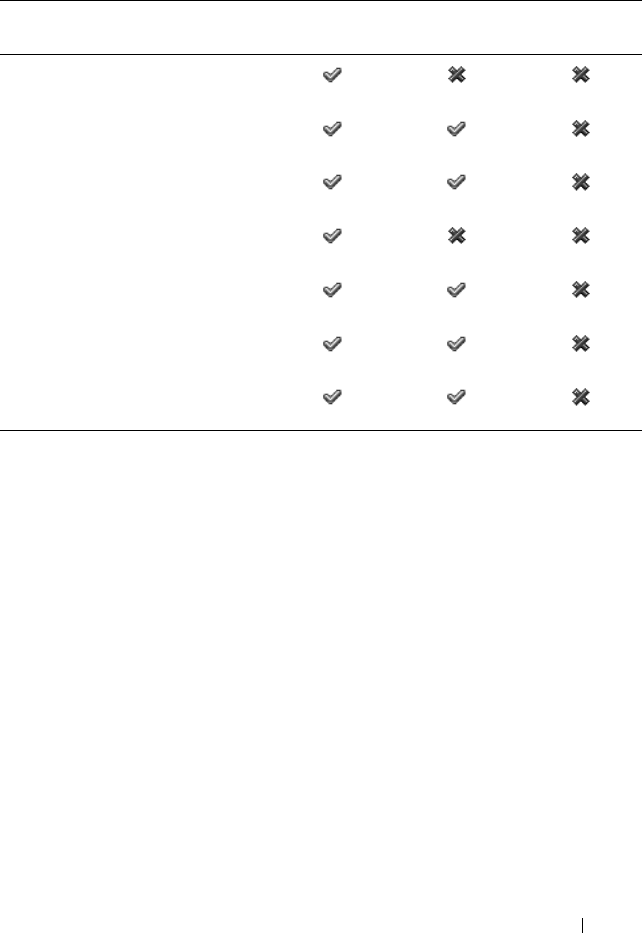
Using the CMC Web Interface 127
Adding and Managing Users
From the Users and User Configuration pages in the Web interface, you can
view information about CMC users, add a new user, and change settings for
an existing user.
You can configure up to 16 local users. If additional users are required and
your company uses the Microsoft® Active Directory® service software, you
can configure Active Directory to provide access to the CMC. Active
Directory configuration would allow you to add and control CMC user
privileges to your existing users in your Active Directory software, in addition
to the 16 local users. For more information, see "Using the CMC With
Microsoft Active Directory" on page 185.
Users can be logged in through Web interface, Telnet serial, SSH, and iKVM
sessions. A maximum of 22 active sessions (Web interface, Telnet serial, SSH,
and iKVM, in any combination) can be divided among users.
Super User
Server Administrator
Test Alert User
Debug Command Administrator
Fabric A Administrator
Fabric B Administrator
Fabric C Administrator
Table 5-11. Comparison of Privileges Between CMC Administrators, Power Users, and
Guest Users (continued)
Privilege Set Administrator
Permissions
Power User
Permissions
Guest User
Permissions

128 Using the CMC Web Interface
NOTE: For added security, Dell strongly recommends that you change the default
password of the root (User 1) account. The root account is the default
administrative account that ships with the CMC. To change the default password for
the root account, click User ID 1 to open the User Configuration page. Help for that
page is available through the Help link at the top right corner of the page.
To add and configure CMC users:
NOTE: You must have User Configuration Administrator privilege to perform the
following steps.
1
Log in to the Web interface.
2
Click the
Network/Security
tab, and then click the
Users sub-tab
. The
Users
page appears, listing
each user’s user ID,
user name, CMC privilege,
and
login state
,
including those of the root user. User IDs available for
configuration will have no user information displayed.
3
Click an available user ID number. The
User Configuration
page displays.
To refresh the contents of the
Users
page, click
Refresh
. To print the
contents of the
Users
age, click
Print
.
4
Select general settings for the user.
Table 5-12 describes the
General
settings for configuring a new or existing
CMC username and password.
Table 5-12. General User Settings
Property Description
User ID (Read only) Identifies a user by one of 16 preset,
sequential numbers used for CLI scripting purposes. The
User ID identifies the particular user when configuring
the user through the CLI tool (RACADM). You cannot
edit the User ID.
If you are editing information for user root, this field is
static. You cannot edit the user name for root.
Enable User Enables or disables the user's access to the CMC.

Using the CMC Web Interface 129
5
Assign the user to a CMC user group. Table 5-9 describes CMC user
privileges. Table 5-10
describes
the
user group permissions
for the
CMC
User Privileges
settings. Table 5-11 provides a comparison of privileges
between Administrators, Power Users, and Guest Users.
When you select a user privilege setting from the CMC Group drop-down
menu, the enabled privileges (shown as checked boxes in the list) display
according to the pre-defined settings for that group.
You can customize the privileges settings for the user by checking or un-
checking boxes. After you have selected a CMC Group or made Custom
user privilege selections, click
Apply Changes
to keep the settings.
6
Click
Apply Changes
.
User Name Sets or displays the unique CMC user name associated
with the user. The user name can contain up to
16 characters. CMC user names cannot include forward
slash (/) or period (.) characters.
NOTE: If you change the user name, the new name does not
appear in the user interface until your next login. Any user
logging in after you apply the new user name will be able to
see the change immediately.
Change Password Allows an existing user’s password to be changed. Set the
new password in the New Password field.
The Change Password check box is not selectable if you
are configuring a new user. You can select it only when
changing an existing user setting.
Password Sets a new password for an existing user. To change the
password, you must also select the Change Password
check box. The password can contain up to 20 characters,
which display as dots as you type.
Confirm Password Verifies the password you entered in the New Password field.
NOTE: The New Password and Confirm New Password
fields are editable only when you are (1) configuring a new
user; or (2) editing the settings for an existing user, and the
Change Password check box is selected.
Table 5-12. General User Settings (continued)
Property Description

130 Using the CMC Web Interface
To refresh the contents of the User Configuration page, click Refresh.
To print the contents of the User Configuration page, click Print.
Configuring and Managing Microsoft Active
Directory Certificates
NOTE: To configure Active Directory settings for the CMC, you must have Chassis
Configuration Administrator privilege.
NOTE: For more information about Active Directory configuration and how to
configure Active Directory with Standard Schema or Extended Schema, see "Using
the CMC With Microsoft Active Directory" on page 185.
You can use the Microsoft Active Directory service to configure your software
to provide access to the CMC. Active Directory service allows you to add and
control the CMC user privileges of your existing users.
To access the Active Directory Main Menu page:
1
Log in to the Web interface.
2
Click the
Network/Security
tab, and then click the
Active Directory sub-
tab
. The
Active Directory Main Menu
page appears.
Table 5-13 lists the Active Directory Main Menu page options.
Table 5-13. Active Directory Main Menu Page Options
Field Description
Configure Configure and manage the following Active Directory
settings for CMC: CMC Name, ROOT Domain Name,
CMC Domain Name, Active Directory Authentication
Timeout, Active Directory Schema Selection (Extended or
Standard), and Role Group settings.
Upload AD Certificate Upload a certificate authority-signed certificate for Active
Directory to the CMC. This certificate, which you obtain
from Active Directory, grants access to the CMC.

Using the CMC Web Interface 131
Configuring Active Directory (Standard Schema and Extended Schema)
NOTE: To configure Active Directory settings for the CMC, you must have Chassis
Configuration Administrator privilege.
NOTE: Before configuring or using the Active Directory feature, you must ensure
that your Active Directory server is configured to communicate with the CMC.
1
Ensure that all Secure Socket Layer (SSL) certificates for the Active
Directory servers are signed by the same certificate authority and have
been uploaded to the CMC.
2
Log in to the Web interface and navigate to the
Active Directory Main
Menu
.
3
Select
Configure
, and then click
Next
. The
Active Directory
Configuration and Management
page displays.
4
Select the
Enable Active Directory
check box under the
Common
Settings
heading.
5
Type the required information into the remaining
fields. See Table 5-14.
Download Certificate Download a CMC server certificate to your management
station or shared network using Windows Download
Manager. When you select this option and click Next, a File
Download dialog box appears. Use this dialog box to specify
a location on your management station or shared network
for the server certificate.
View Certificate Displays the certificate authority-signed server certificate
for Active Directory that has been uploaded to the CMC.
NOTE: By default, CMC does not have a certificate authority-
issued server certificate for Active Directory. You must upload
a current, certificate authority-signed server certificate.
Table 5-13. Active Directory Main Menu Page Options (continued)
Field Description

132 Using the CMC Web Interface
6
Select an Active Directory schema under the Active Directory Schema
Selection heading. See Table 5-15.
Table 5-14. Active Directory Common Settings Properties
Setting Description
Root Domain Name Specifies the domain name used by Active Directory. The
root domain name is the fully qualified root domain name
for the forest.
NOTE: The root domain name must be a valid domain name
using the x.y naming convention, where x is a 1–256 character
ASCII string with no spaces between characters, and y is a
valid domain type such as com, edu, gov, int, mil, net, or org.
Default: null (empty)
AD Timeout The time in seconds to wait for Active Directory queries to
complete. The minimum value is equal to or greater than 15
seconds.
Default: 120 seconds
Specify AD Server to
search (Optional)
Enables (when checked) directed call on the domain
controller and global catalog. If you enable this option, you
must also specify the domain controller and global catalog
locations in the following settings.
NOTE: The name on the Active Directory CA Certificate will
not be matched against the specified Active Directory server
or the Global Catalog server.
Domain Controller Specifies the server where your Active Directory service is
installed.
This option is valid only if Specify AD Server to search
(OPTIONAL) is enabled.
Global Catalog Specifies the location of the global catalog on the Active
Directory domain controller. The global catalog provides a
resource for searching an Active Directory forest.
This option is valid only if Specify AD Server to search
(OPTIONAL) is enabled.

Using the CMC Web Interface 133
7
If you selected
Extended Schema
, type the following required information
in the Extended Schema Settings section, and then proceed directly to
step 9. If you selected Standard Schema, proceed to step 8.
•
CMC Device Name
– The name that uniquely identifies the CMC
card in Active Directory. The CMC name must be the same as the
common name of the new CMC object you created in your Domain
Controller. The name must be a 1–256 character ASCII string with no
spaces between characters. Default: null (empty).
•
CMC Domain Name
– The DNS name (string) of the domain where
the Active Directory CMC object resides (example: cmc.com). The
name must be a valid domain name consisting of
x.y
, where
x
is a
1–256 character ASCII string with no spaces between characters, and
y
is a valid domain type such as com, edu, gov, int, mil, net, or org.
Default
:
null (empty).
NOTE: Do not use the NetBIOS name. The CMC Domain Name is the fully
qualified domain name of the sub-domain where the CMC Device Object is
located.
Table 5-15. Active Directory Schema Options
Setting Description
Use Standard Schema Uses Standard Schema with Active Directory, which uses
Active Directory group objects only.
Before configuring CMC to use the Active Directory
Standard Schema option, you must first configure the
Active Directory software:
1
On an Active Directory server (domain controller), open
the Active Directory Users and Computers Snap-in.
2
Create a group or select an existing group. The name of the
group and the name of this domain must be configured on
the CMC either with the Web interface or RACADM.

134 Using the CMC Web Interface
8
If you selected Standard Schema, type the following information in the
Standard Schema Settings section. If you selected Extended Schema,
proceed to step 9.
•
Role Groups
– The role groups associated with the CMC. To change
the settings for a role group, click the role group number in the Role
Groups list. The
Configure Role Group
page displays.
NOTE: If you click a role group link prior to applying any new settings you
have made, you will lose those settings. To avoid losing any new settings,
click Apply before clicking a role group link.
•
Group Name
– The name that identifies the role group in the Active
Directory associated with the CMC card.
•
Group Domain
– The domain where the group is located.
•
Group Privilege
– The privilege level for the group.
9
Click
Apply
to save the settings.
To refresh the contents of the
Active Directory Configuration and
Management
page, click Refresh.
To print the contents of the
Active Directory Configuration and Management
page, click Print.
Use Extended Schema Uses Extended Schema with Active Directory, which uses
Dell-defined Active Directory objects.
Before configuring CMC to use the Active Directory
Extended Schema option, you must first configure the
Active Directory software:
1
Extend the Active Directory schema.
2
Extend the Active Directory Users and Computers Snap-
in.
3
Add CMC users and their privileges to Active Directory.
4
Enable SSL on each of your domain controllers.
5
Configure the CMC Active Directory properties using
either the CMC Web interface or the RACADM.
Table 5-15. Active Directory Schema Options (continued)
Setting Description

Using the CMC Web Interface 135
To configure the Role Groups for Active Directory, click the individual Role
Group (1–5). See Table 5-10 and Table 5-9).
NOTE: To save the settings on the Active Directory Configuration and Management
page, you have to click Apply before proceeding to the Custom Role Group page.
Uploading an Active Directory Certificate Authority-Signed Certificate
From
the
Active Directory Main Menu
page
:
1
Select
Upload AD Certificate,
and then click
Next
. The
Certificate
Upload page displays.
2
Type the file path in the text field, or click
Browse
to select the file.
NOTE: The File Path value displays the relative file path of the certificate you are
uploading. You must type the absolute file path, which includes the full path and the
complete file name and file extension.
3
Click
Apply
. If the certificate is invalid, an error message displays.
To refresh the contents of the
Upload Active Directory CA Certificate
page,
click Refresh.
To print the contents of the
Upload Active Directory CA Certificate
page,
click Print.
Viewing an Active Directory Certificate Authority-Signed Certificate
NOTE: If you uploaded an Active Directory server certificate on the CMC, make
sure the certificate is still valid and has not expired.
From
the
Active Directory Main Menu
page
:
1
Select
View Certificate,
and then click
Next
.
2
Click the appropriate
View Active Directory CA Certificate
page button
to continue.
Table 5-16. Active Directory CA Certificate Information
Field Description
Serial Number Certificate serial number.
Subject Information Certificate attributes entered by the subject.
Issuer Information Certificate attributes returned by the issuer.

136 Using the CMC Web Interface
To refresh the contents of the
View Active Directory CA Certificate
page,
click Refresh.
To print the contents of the
View Active Directory CA Certificate
page, click
Print.
Securing CMC Communications Using SSL and
Digital Certificates
This subsection provides information about the following data security
features that are incorporated in your CMC:
• Secure Sockets Layer (SSL)
• Certificate Signing Request (CSR)
• Accessing the SSL main menu
• Generating a new CSR
• Uploading a server certificate
• Viewing a server certificate
Secure Sockets Layer (SSL)
The CMC includes a Web server that is configured to use the industry-
standard SSL security protocol to transfer encrypted data over the Internet.
Built upon public-key and private-key encryption technology, SSL is a widely
accepted technique for providing authenticated and encrypted
communication between clients and servers to prevent eavesdropping across a
network.
SSL allows an SSL-enabled system to perform the following tasks:
• Authenticate itself to an SSL-enabled client
• Allow the client to authenticate itself to the server
• Allow both systems to establish an encrypted connection
Valid From Certificate issue date.
Valid To Certificate expiration date.
Table 5-16. Active Directory CA Certificate Information (continued)
Field Description

Using the CMC Web Interface 137
This encryption process provides a high level of data protection. The CMC
employs the 128-bit SSL encryption standard, the most secure form of
encryption generally available for Internet browsers in North America.
The CMC Web server includes a Dell self-signed SSL digital certificate
(Server ID). To ensure high security over the Internet, replace the Web server
SSL certificate by submitting a request to the CMC to generate a new
Certificate Signing Request (CSR).
Certificate Signing Request (CSR)
A CSR is a digital request to a certificate authority (referred to as a CA in the
Web interface) for a secure server certificate. Secure server certificates ensure
the identity of a remote system and ensure that information exchanged with
the remote system cannot be viewed or changed by others. To ensure the
security for your CMC, it is strongly recommended that you generate a CSR,
submit the CSR to a certificate authority, and upload the certificate returned
from the certificate authority.
A certificate authority is a business entity that is recognized in the IT industry
for meeting high standards of reliable screening, identification, and other
important security criteria. Examples of CAs include Thawte and VeriSign.
After the certificate authority receives your CSR, they review and verify the
information the CSR contains. If the applicant meets the certificate
authority’s security standards, the certificate authority issues a certificate to
the applicant that uniquely identifies that applicant for transactions over
networks and on the Internet.
After the certificate authority approves the CSR and sends you a certificate,
you must upload the certificate to the CMC firmware. The CSR information
stored on the CMC firmware must match the information contained in the
certificate.
Accessing the SSL Main Menu
NOTE: To configure SSL settings for the CMC, you must have Chassis Configuration
Administrator privilege.

138 Using the CMC Web Interface
NOTE: Any server certificate you upload must be current (not expired) and signed
by a certificate authority.
1
Log in to the Web interface.
2
Click the
Network/Security
tab, and then click the
SSL sub-tab
. The
SSL
Main Menu
page appears.
Use the SSL Main Menu page options to generate a CSR to send to a
certificate authority. The CSR information is stored on the CMC firmware.
Generating a New Certificate Signing Request
To ensure security, Dell strongly recommends that you obtain and upload a
secure server certificate to the CMC. Secure server certificates ensure the
identity of a remote system and that information exchanged with the remote
system cannot be viewed or changed by others. Without a secure server
certificate, the CMC is vulnerable to access from unauthorized users.
Table 5-17. SSL Main Menu Options
Field Description
Generate a New
Certificate Signing
Request (CSR)
Select this option and click Next to open the Generate
Certificate Signing Request (CSR) page, where you can
generate a CSR request for a secure Web certificate to
submit to a certificate authority.
NOTICE: Each new CSR overwrites any previous CSR
on the CMC. For a certificate authority to accept your
CSR, the CSR in the CMC must match the certificate
returned from the certificate authority.
Upload Server
Certificate
Select this option and click Next to open the Certificate
Upload page, where you can upload an existing certificate
that your company holds title to and uses to control access
to the CMC.
NOTICE: Only X509, Base 64-encoded certificates are
accepted by the CMC. DER-encoded certificates are not
accepted. Uploading a new certificate replaces the
default certificate you received with your CMC.
View Server Certificate Select the option and click the Next button to open the
View Server Certificate page where you can view the
current server certificate.

Using the CMC Web Interface 139
To obtain a secure server certificate for the CMC, you must submit a
Certificate Signing Request (CSR) to a certificate authority of your choice. A
CSR is a digital request for a signed, secure server certificate containing
information about your organization and a unique, identifying key.
When a CSR is generated from the Generate Certificate Signing Request
(CSR) page, you are prompted to save a copy to your management station or
shared network, and the unique information used to generate the CSR is
stored on the CMC. This information is used later to authenticate the server
certificate you receive from the certificate authority. After you receive the
server certificate from the certificate authority, you must then upload it to the
CMC.
NOTE: For the CMC to accept the server certificate returned by the certificate
authority, authentication information contained in the new certificate must match
the information that was stored on the CMC when the CSR was generated.
NOTICE: When a new CSR is generated, it overwrites any previous CSR on the
CMC. If a pending CSR is overwritten before its server certificate is granted from a
certificate authority, the CMC will not accept the server certificate because the
information it uses to authenticate the certificate has been lost. Take caution when
generating a CSR to prevent overwriting any pending CSR.
To generate a CSR:
1
From the
SSL Main Menu
page, select
Generate a New Certificate
Signing Request (CSR)
, and then click
Next
. The
Generate Certificate
Signing Request (CSR)
page displays.
2
Type a value for each CSR attribute value.
Table 5-18 describes the
Generate Certificate Signing Request (CSR)
page options.
3
Click
Generate
. A
File Download
dialog box appears.
4
Save the
csr.txt
file to your management station or shared network. (You
may also open the file at this time and save it later.) You will later submit
this file to a certificate authority.

140 Using the CMC Web Interface
Table 5-18. Generate Certificate Signing Request (CSR) Page Options
Field Description
Common Name The exact name being certified (usually the Web server's
domain name, for example, www.xyzcompany.com/).
Val id: Alphanumeric characters (A–Z, a–z, 0–9); hyphens,
underscores, and periods.
Not valid: Non-alphanumeric characters not noted above (such
as, but not limited to, @ # $ % & *); characters used primarily
in non-English languages, such as ß, å, é, ü.
Organization Name The name associated with your organization (example: XYZ
Corporation).
Val id: Alphanumeric characters (A–Z, a–z, 0–9); hyphens,
underscores, periods, and spaces.
Not valid: Non-alphanumeric characters not noted above (such
as, but not limited to, @ # $ % & *).
Organization Unit The name associated with an organizational unit, such as a
department (example: Enterprise Group).
Val id: Alphanumeric characters (A–Z, a–z, 0–9); hyphens,
underscores, periods, and spaces.
Not valid: Non-alphanumeric characters not noted above (such
as, but not limited to, @ # $ % & *).
Locality The city or other location of your organization (examples:
Atlanta, Hong Kong).
Val id: Alphanumeric characters (A–Z, a–z, 0–9) and spaces.
Not Valid: Non-alphanumeric characters not noted above (such
as, but not limited to, @ # $ % & *).
State The state, province, or territory where the entity that is applying
for a certification is located (examples: Texas, New South
Wales, Andhra Pradesh).
NOTE: Do not use abbreviations.
Val id: Alphanumeric characters (upper- and lower-case letters;
0–9); and spaces.
Not valid: Non-alphanumeric characters not noted above (such
as, but not limited to, @ # $ % & *).

Using the CMC Web Interface 141
Uploading a Server Certificate
1
From the
SSL Main Menu
page, select
Upload Server Certificate
, and
then click
Next
. The
Certificate Upload
page displays.
2
Type the file path in the text field, or click
Browse
to select the file.
3
Click
Apply
. If the certificate is invalid, an error message displays.
NOTE: The File Path value displays the relative file path of the certificate you are
uploading. You must type the absolute file path, which includes the full path and the
complete file name and file extension.
To refresh the contents of the
Certificate Upload
page, click Refresh.
To print the contents of the
Certificate Upload
page, click Print.
Viewing a Server Certificate
From the SSL Main Menu page, select View Server Certificate, and then
click Next. The View Server Certificate page displays.
Table 5-19 describes the fields and associated descriptions listed in the
Certificate window.
Country The country where the organization applying for certification is
located.
Email Your organization's email address. You may type any email
address you want to have associated with the CSR. The email
address must be valid, containing the at (@) sign (example:
name@xyzcompany.com).
Table 5-19. Certificate Information
Field Description
Serial Certificate serial number
Subject Certificate attributes entered by the subject
Issuer Certificate attributes returned by the issuer
Table 5-18. Generate Certificate Signing Request (CSR) Page Options (continued)
Field Description

142 Using the CMC Web Interface
To refresh the contents of the View
Server Certificate
page, click Refresh.
To print the contents of the View
Server Certificate
page, click Print.
Managing Sessions
The Sessions page displays all current instances of connections to the chassis
and allows you to terminate any active session.
NOTE: To terminate a session, you must have Chassis Configuration Administrator
privilege.
To manage sessions:
1
Log in to the CMC Web interface.
2
Select
Chassis
in the system tree.
3
Click the
Network/Security
tab.
4
Click the
Sessions
sub-tab. The
Sessions
page appears.
notBefore Issue date of the certificate
notAfter Expiration date of the certificate
Table 5-20. Sessions Properties
Property Description
Session ID Displays the sequentially generated ID number for each instance
of a login.
Username Displays the user's login name (local user or Active Directory user).
Examples of Active Directory user names are name@domain.com,
domain.com/name, domain.com\name.
IP Address Displays the user’s IP address in dot-separated format.
Session Type Describes the session type: Telnet, serial, SSH, Remote RACADM,
SMASH CLP, WSMAN, or a GUI session.
Table 5-19. Certificate Information (continued)
Field Description
Using the CMC Web Interface 143
To terminate the session, click the trash can icon on the line that describes
the session.
Configuring Services
The CMC includes a Web server that is configured to use the industry-
standard SSL security protocol to accept and transfer encrypted data from
and to clients over the Internet. The Web server includes a Dell self-signed
SSL digital certificate (Server ID) and is responsible for accepting and
responding to secure HTTP requests from clients. This service is required by
the Web interface and remote CLI tool for communicating to the CMC.
NOTE: The remote (RACADM) CLI tool and the Web interface use the Web server.
In the event that the Web Server is not active, the remote RACADM and the Web
interface are not operable.
NOTE: In an event of a Web server reset, wait at least one minute for the services
to become available again. A Web server reset usually happens as a result of any of
the following events: the network configuration or network security properties are
changed through the CMC Web user interface or RACADM; the Web Server port
configuration is changed through the Web user interface or RACADM; the CMC is
reset; a new SSL server certificate is uploaded.
NOTE: To modify service settings, you must have Chassis Configuration
Administrator privilege.
To configure CMC services:
1
Log in to the CMC Web interface.
2
Click the
Network/Security
tab.
3
Click the
Services
sub-tab. The
Services
page appears.
Terminate Allows you to terminate any of the sessions listed, except for your
own. To terminate the associated session, click the trash can
icon . This column is displayed only if you have Chassis
Configuration Administrator privileges.
Table 5-20. Sessions Properties (continued)
Property Description

144 Using the CMC Web Interface
4
Configure the following services as required:
• CMC serial console (Table 5-21)
• Web server (Table 5-22)
• SSH (Table 5-23)
• Telnet (Table 5-24)
• Remote RACADM (Table 5-25)
5
Click
Apply;
update all default time outs and maximum time out limits.
Table 5-21. CMC Serial Console Settings
Setting Description
Enabled Enables Telnet console interface on the CMC.
Default: Unchecked (disabled)
Redirect Enabled Enables the serial/text console redirection to the server
through your Telnet client from the CMC. The CMC
connects to iDRAC, which internally connects to the server.
Configuration options: Checked (enabled), unchecked
(disabled)
Default: Unchecked (disabled)
Idle Timeout Indicates the number of seconds before an idle Telnet
session is automatically disconnected. A change to the
Timeout setting takes effect at the next login; it does not
affect the current session.
Timeout Range: 0 or 60 to 10800 seconds. To disable the
Timeout feature, enter 0.
Default: 1800 seconds
Baud Rate Indicates the data speed on the external serial port on the
CMC.
Configuration options: 9600, 19200, 28800, 38400, 57600,
and 115200 bps.
Default: 115200 bps
Authentication
Disabled
Enables CMC Serial Console login authentication.
Default: Unchecked (disabled)

Using the CMC Web Interface 145
Escape Key Allows you to specify the Escape key combination that
terminates serial/text console redirection when using the
connect com2 command.
Default: ^\
(Hold <Ctrl> and type a backslash (\) character)
NOTE: The caret character ^ represents the <Ctrl> key.
Configuration options:
• Decimal value (example: 95)
• Hexadecimal value (example: 0x12)
• Octal value (example: 007)
• ASCII value (example: ^a)
ASCII values may be represented using the following
Escape key codes:
• Esc followed by any alphabetic character (a-z, A-Z)
• Esc followed by the following special characters: [ ] \ ^ _
• Maximum Allowed Length: 4
History Size Buffer Indicates the maximum size of the serial history buffer,
which holds the last characters written to the Serial
Console.
Default: 8192 characters
Login Command Specifies the serial command that is automatically
executed when a user logs into the CMC Serial Console
interface.
Example: connect server-1
Default: [Null]
Table 5-21. CMC Serial Console Settings (continued)
Setting Description

146 Using the CMC Web Interface
Table 5-22. Web Server Settings
Setting Description
Enabled Enables Web Server services (access through remote
RACADM and the Web interface) for the CMC.
Default: Checked (enabled)
Max Sessions Indicates the maximum number of simultaneous Web user
interface sessions allowed for the chassis. A change to the
Max Sessions property takes effect at the next login; it does
not affect current Active Sessions (including your own).
The remote RACADM is not affected by the Max Sessions
property for the Web Server.
Allowed range: 1–4
Default: 4
NOTE: If you change the Max Sessions property to a value
less than the current number of Active Sessions and then log
out, you cannot log back in until the other sessions have been
terminated or expired.
Idle Timeout Indicates the number of seconds before an idle Web user
interface session is automatically disconnected. A change to
the Timeout setting takes effect at the next login; it does
not affect the current session.
Timeout range: 60 to 10800 seconds.
Default: 1800 seconds

Using the CMC Web Interface 147
HTTP Port Number Indicates the default port used by the CMC that listens for
a server connection.
NOTE: When you provide the HTTP address on the browser,
the Web server automatically redirects and uses HTTPS.
If the default HTTP port number (80) has been changed,
you must include the port number in the address in the
browser address field, as shown:
http://<
IP address
>:<
port number
>
where IP address is the IP address for the chassis, and port
number is the HTTP port number other than the default
of 80.
Configuration range: 10–65535
Default: 80
HTTPS Port Number Indicates the default port used by the CMC that listens for
a secured server connection.
If the default HTTPS port number (443) has been changed,
you must include the port number in the address in the
browser address field, as shown:
http://<
IP address
>:<
port number
>
where <IP address> is the IP address for the chassis, and
<port number> is the HTTPS port number other than the
default of 443.
Configuration range: 10–65535
Default: 443
Table 5-22. Web Server Settings (continued)
Setting Description

148 Using the CMC Web Interface
Table 5-23. SSH Settings
Setting Description
Enabled Enables the SSH on the CMC.
Default: Checked (enabled)
Max Sessions The maximum number of simultaneous SSH sessions
allowed for the chassis. A change to this property takes
effect at the next login; it does not affect current Active
Sessions (including your own).
Configurable range: 1–4
Default: 4
NOTE: If you change the Max Sessions property to a value
less than the current number of Active Sessions and then log
out, you cannot log back in until the other sessions have been
terminated or expired.
Idle Timeout Indicates the number of seconds before an idle SSH session
is automatically disconnected. A change to the Timeout
setting takes effect at the next login; it does not affect the
current session.
Timeout Range: 0 or 60–10800 seconds. To disable the
Timeout feature, enter 0.
Default: 1800 seconds
Port Number Port used by the CMC that listens for a server connection.
Configuration range: 10–65535
Default: 22

Using the CMC Web Interface 149
Table 5-24. Telnet Settings
Setting Description
Enabled Enables Telnet console interface on the CMC.
Default: Unchecked (disabled)
Max Sessions Indicates the maximum number of simultaneous Telnet
sessions allowed for the chassis. A change to this property
takes effect at the next login; it does not affect current
Active Sessions (including your own).
Allowed range: 1–4
Default: 4
NOTE: If you change the Max Sessions property to a value
less than the current number of Active Sessions and then log
out, you cannot log back in until the other sessions have been
terminated or expired.
Idle Timeout Indicates the number of seconds before an idle Telnet
session is automatically disconnected. A change to the
Timeout setting takes effect at the next login; it does not
affect the current session.
Timeout Range: 0 or 60–10800 seconds. To disable the
Timeout feature, enter 0.
Default: 1800 seconds
Port Number Indicates the port used by the CMC that listens for a server
connection.
Default: 23

150 Using the CMC Web Interface
Configuring Power Budgeting
The CMC allows you to budget and manage power to the chassis. The power
management service optimizes power consumption and re-allocates power to
different modules based on the demand.
For instructions on configuring power through the CMC, see "Configuring
and Managing Power" on page 222.
For more information on the CMC’s power management service, see "Power
Management" on page 215.
Table 5-25. Remote RACADM Settings
Setting Description
Enabled Enables the remote RACADM utility access to the CMC.
Default: Checked (enabled)
Max Sessions Indicates the maximum number of simultaneous
RACADM sessions allowed for the chassis. A change to this
property takes effect at the next login; it does not affect
current Active Sessions (including your own).
Allowed range: 1–4
Default: 4
NOTE: If you change the Max Sessions property to a value
less than the current number of Active Sessions and then log
out, you cannot log back in until the other sessions have been
terminated or expired.
Idle Timeout Indicates the number of seconds before an idle racadm
session is automatically disconnected. A change to the Idle
Timeout setting takes effect at the next login; it does not
affect the current session. To disable the Idle Timeout
feature, enter 0.
Timeout Range: 0, or 10 to 1920 seconds. To disable the
Timeout feature, enter 0.
Default: 30 seconds

Using the CMC Web Interface 151
Managing Firmware
This section describes how to use the Web interface to update firmware. The
following components can be updated using the GUI or RACADM
commands:
• CMC - primary and standby.
•iKVM
• iDRAC (boot-block mode only)
• IOM infrastructure devices
When you update firmware, there is a recommended process to follow that
can prevent a loss of service if the update fails. See "Installing or Updating the
CMC Firmware" on page 52 for guidelines to follow before you use the
instructions in this section.
Viewing the Current Firmware Versions
The Updatable Components page displays the current version of the iKVM
firmware, primary CMC firmware, (if applicable) the standby CMC firmware,
the iDRAC firmware, and the IOM infrastructure device firmware. Clicking
on either the device name or the firmware version will display a Device
Update page for that particular device.
The Device Update page displays only one device at a time, except in the case
of the CMC where both the standby and active CMCs are displayed if both
are updatable. Only the standby and active CMC can be updated at the same
time with the same action from the Web interface; all other devices (IOMs or
servers) must be updated one at a time. To update multiple servers and
IOMs, refer to "fwupdate" on page 329 for information on the fwupdate
command.
If the chassis contains a server whose iDRAC is in recovery mode or if the
CMC detects that an iDRAC has corrupted firmware, the iDRAC is also
listed on the Updatable Components page. See "Recovering iDRAC
Firmware Using the CMC" on page 157 for the steps to recover iDRAC
firmware using the CMC.

152 Using the CMC Web Interface
To view firmware versions:
1
Log in to the Web interface (see "Accessing the CMC Web Interface" on
page 93).
2
Click
Chassis
in the system tree.
3
Click the
Update
tab. The
Updatable Components
page appears.
Updating Firmware
NOTE: To update firmware on the CMC, you must have Chassis Configuration
Administrator privilege.
NOTE: The firmware update retains the current CMC and iKVM settings.
NOTE: If a web user interface session is used to update system component
firmware, the "Idle Timeout" setting must be set high enough to accommodate the
file transfer time. In some cases, the firmware file transfer time may be as high as
30 minutes. To set the "Idle Timeout" value, see "Configuring Services" on page 143.
NOTE: The iDRAC firmware is updatable through the iDRAC Web-based user
interface or remote RACADM. However, if the CMC user interface detects the
presence of a server but is unable to communicate with it, it indicates a corruption.
In such cases, iDRAC Firmware Update will be available from the Updatable
Components page. To open the Updatable Components page, select Chassis in the
system tree, and then click the Update tab.
The Updatable Components page displays the current version of the
firmware for each listed component and allows you to update the firmware to
the latest revision by uploading the firmware image file (package).
NOTE: Be sure you have the latest firmware version. You can download the latest
firmware image file from the Dell Support website.
Updating the CMC Firmware
NOTE: During updates of the CMC firmware or the iDRAC firmware on a server,
some or all of the fan units in the chassis will spin at 100%. This is normal.
NOTE: The Active (primary) CMC resets and becomes temporarily unavailable after
the firmware has been uploaded successfully. If a standby CMC is present, the
standby and active roles will swap; the standby (secondary) CMC becomes the
active (primary) CMC. If an update is applied only to the active (primary) CMC, after
the reset is complete the primary CMC will not be running the updated image, only
the standby (secondary) will have that image.

Using the CMC Web Interface 153
NOTE: To avoid disconnecting other users during a reset, notify authorized users
who might log in to the CMC and check for active sessions by viewing the Sessions
page. To open the Sessions page, select Chassis in the tree, click the
Network/Security tab, and then click the Sessions sub-tab. Help for that page is
available through the Help link at the top right corner of the page.
NOTE: When transferring files to and from the CMC, the file transfer icon spins
during the transfer. If your icon is not animated, make sure that your browser is
configured to allow animations. See "Allow Animations in Internet Explorer" on
page 40 for instructions.
NOTE: If you experience problems downloading files from CMC using Internet
Explorer, enable the Do not save encrypted pages to disk option. See "Downloading
Files From CMC With Internet Explorer" on page 40 for instructions.
1
On the
Updatable Components
page, click the CMC name. The
Firmware Update
page appears. The active, and, if present, the standby,
CMCs are listed and selected. Both CMCs can be updated at the same
time.
2
In the
Firmware Image
field, enter the path to the firmware image file on
your management station or shared network, or click
Browse
to navigate to
the file location.
NOTE: The default CMC firmware image name is firmimg.cmc. The CMC firmware
should be updated first, before updating IOM infrastructure device firmware.
3
Click
Begin Firmware Update
. A dialog box prompts you to confirm the
action.
4
Click
Yes
to continue. The
Firmware Update Progress
section provides
firmware update status information. A status indicator displays on the
page while the image file uploads. File transfer time can vary greatly based
on connection speed. When the internal update process begins, the page
automatically refreshes and the Firmware update timer displays.
Additional items to note:
• Do not use the
Refresh
button or navigate to another page during the
file transfer.
• To cancel the process, click
Cancel File Transfer and Update
- this
option is available only during file transfer.

154 Using the CMC Web Interface
• Update status displays in the
Update State
field; this field is
automatically updated during the file transfer process. Certain older
browsers do not support these automatic updates. To manually refresh
the
Update State
field, click
Refresh
.
NOTE: The update may take several minutes for the CMC.
5
For a standby (secondary) CMC, when the update is complete the Update
State field displays "Done". For an active (primary) CMC, during the final
phases of the firmware update process, the browser session and connection
with the CMC will be lost temporarily as the active (primary) CMC is
taken off line. You must log in again after a few minutes, when the active
(primary) CMC has rebooted.
After the CMC resets, the new firmware is updated and displayed on the
Updatable Components page.
NOTE: After the firmware update, clear the Web browser cache. See your Web
browser’s online help for instructions on how to clear the browser cache.
Updating the iKVM Firmware
NOTE: The iKVM resets and becomes temporarily unavailable after the firmware
has been uploaded successfully.
1
Log back in to the CMC Web interface.
2
Select
Chassis
in the system tree.
3
Click the
Update
tab. The
Updatable Components
page appears.
4
Click the iKVM name. The
Firmware Update
page appears.
5
In the
Firmware Image
field, enter the path to the firmware image file on
your management station or shared network, or click
Browse
to navigate to
the file location.
NOTE: The default iKVM firmware image name is ikvm.bin; however, the iKVM
firmware image name can be changed by the user.
6
Click
Begin Firmware Update
. A dialog box prompts you to confirm the
action.
7
Click
Yes
to continue. The
Firmware Update Progress
section provides
firmware update status information. A status indicator displays on the
page while the image file uploads. File transfer time can vary greatly based

Using the CMC Web Interface 155
on connection speed. When the internal update process begins, the page
automatically refreshes and the Firmware update timer displays.
Additional items to note:
• Do not use the
Refresh
button or navigate to another page during the
file transfer.
• To cancel the process, click
Cancel File Transfer and Update
- this
option is available only during file transfer.
• Update status displays in the
Update State
field; this field is
automatically updated during the file transfer process. Certain older
browsers do not support these automatic updates. To manually refresh
the
Update State
field, click
Refresh
.
NOTE: The update may take up to one minute for the iKVM.
When the update is complete, iKVM resets and the new firmware is updated
and displayed on the Updatable Components page.
Updating the IOM Infrastructure Device Firmware
By performing this update, the firmware for an infrastructure component of
the IOM device is updated.
1
Log back in to the CMC Web interface.
2
Select
Chassis
in the system tree.
3
Click the
Update
tab. The
Updatable Components
page appears.
4
Click the IOM Infrastructure device name. The
Firmware Update
page
appears.
5
In the
Firmware Image
field, enter the path to the firmware image file on
your management station or shared network, or click
Browse
to navigate to
the file location.
NOTE: The Firmware Image field does not display for an IOM infrastructure device
(IOMINKF) target because the required image resides on the CMC. The CMC
firmware should be updated first, before updating IOMINF firmware.
6
Click
Begin Firmware Update
. A dialog box prompts you to confirm the
action.
7
Click
Yes
to continue. The
Firmware Update Progress
section provides
firmware update status information. A status indicator displays on the
page while the image file uploads. File transfer time can vary greatly based

156 Using the CMC Web Interface
on connection speed. When the internal update process begins, the page
automatically refreshes and the Firmware update timer displays.
Additional items to note:
• Do not use the
Refresh
button or navigate to another page during the
file transfer.
• To cancel the process, click
Cancel File Transfer and Update
- this
option is available only during file transfer.
• Update status displays in the
Update State
field; this field is
automatically updated during the file transfer process. Certain older
browsers do not support these automatic updates. To manually refresh
the
Update State
field, click
Refresh
.
NOTE: No file transfer timer is displayed when updating IOMINF firmware. The
update process will cause a brief loss of connectivity to the IOM device since the
device will perform a restart when the update is complete.
When the update is complete, the new firmware is updated and displayed on
the Updatable Components page.
Updating the Server iDRAC Firmware
NOTE: The iDRAC (on a Server) will reset and become temporarily unavailable
after firmware updates have been uploaded successfully.
1
Log back in to the CMC Web interface.
2
Select
Chassis
in the system tree.
3
Click the
Update
tab. The
Updatable Components
page appears.
4
Click the Server name. The
Firmware Update
page appears.
5
In the
Firmware Image
field, enter the path to the firmware image file on
your management station or shared network, or click
Browse
to navigate to
the file location.
6
Click
Begin Firmware Update
. A dialog box prompts you to confirm the
action.
7
Click
Yes
to continue. The
Firmware Update Progress
section provides
firmware update status information. A status indicator displays on the
page while the image file uploads. File transfer time can vary greatly based

Using the CMC Web Interface 157
on connection speed. When the internal update process begins, the page
automatically refreshes and the Firmware update timer displays.
Additional items to note:
• Do not use the
Refresh
button or navigate to another page during the
file transfer.
• To cancel the process, click
Cancel File Transfer and Update
- this
option is available only during file transfer.
• Update status displays in the
Update State
field; this field is
automatically updated during the file transfer process. Certain older
browsers do not support these automatic updates. To manually refresh
the
Update State
field, click
Refresh
.
NOTE: The update may take several minutes for the CMC or Server.
When the update is complete, the updated Server will no longer be present
on the Updatable Components page.
Recovering iDRAC Firmware Using the CMC
iDRAC firmware is typically updated using iDRAC facilities such as the
iDRAC Web interface, the SM-CLP command line interface, or operating
system specific update packages downloaded from support.dell.com. See the
iDRAC Firmware User’s Guide for instructions for updating the iDRAC
firmware.
If the iDRAC firmware becomes corrupted, as could occur if the iDRAC
firmware update progress is interrupted before it completes, you can use the
CMC Web interface to update its firmware.
If the CMC detects the corrupted iDRAC firmware, the iDRAC is listed on
the Updatable Components page. See "Viewing the Current Firmware
Versions" on page 151 for instructions to display the Updatable Components
page.

158 Using the CMC Web Interface
NOTE: If the iDRAC MAC address has been lost or corrupted, it must be set to a
valid address before you can recover the iDRAC firmware using the CMC. You can
use the IPMI config params command to set a MAC address. The MAC address is
the fifth parameter of the command. It must be set to a 6-byte address that is unique
on your management network. Refer to the documentation for your IPMI utility (for
example, ipmitool or ipmish) for help executing the command.
Follow these steps to update the iDRAC firmware.
1
Download the latest iDRAC firmware to your management computer from
support.dell.com
.
2
Log in to the Web interface (see "Accessing the CMC Web Interface" on
page 93).
3
Click
Chassis
in the system tree.
4
Click the
Update
tab. The
Updatable Components
page appears. The
server with the recoverable iDRAC is included in the list if it is able to be
recovered from the CMC.
5
Click
server-n
, where
n
is the number of the server whose iDRAC you want
to recover.
6
Click
Browse
, browse to the iDRAC firmware image you downloaded, and
click
Open
.
NOTE: The default iDRAC firmware image name is firmimg.imc.
7
Click
Begin Firmware Update
.
NOTE: It can take up to ten minutes to update the iDRAC firmware. The file transfer
icon spins while the firmware image is transferred to the CMC, but not while the
CMC transfers the image to the iDRAC.
After the firmware image file has been uploaded to the CMC, the iDRAC will
update itself with the image.
FlexAddress
This section describes the FlexAddress feature Web interface screens.
FlexAddress is an optional upgrade that allows server modules to replace the
factory assigned WWN/MAC ID with a WWN/MAC ID provided by the
chassis.

Using the CMC Web Interface 159
NOTE: You must purchase and install the FlexAddress upgrade to have access to
the configuration screens. If the upgrade has not been purchased and installed, the
following text will be displayed on the Web interface:
Optional feature not installed. See the
Dell
Chassis Management Controller Users Guide
for
information on the chassis-based WWN and MAC
address administration feature.
To purchase this feature, please contact Dell at
www.dell.com.
Viewing FlexAddress Status
You can use the Web interface to view FlexAddress status information. You
can view status information for the entire chassis or for an individual server.
The information displayed includes:
• Fabric configuration
• FlexAddress active/not active
• Slot number and name
• Chassis-assigned and server-assigned addresses
• Addresses in use
NOTE: You can also view FlexAddress status using the command line interface. For
more command information, see "Using FlexAddress" on page 169.
Viewing Chassis FlexAddress Status
FlexAddress status information can be displayed for the entire chassis. The
status information includes whether the feature is active and an overview of
the FlexAddress status for each blade.
Use the following steps to view whether FlexAddress is active for the chassis:
1
Log in to the Web interface (see "Accessing the CMC Web Interface" on
page 93).
2
Click
Chassis
in the system tree.
3
Click the
Setup
tab. The
General Setup
page appears. The FlexAddress
entry will have a value of
Active
or
Not Active
; a value of active means that
the feature is installed on the chassis. A value of not active means that the
feature is not installed and not in use on the chassis.

160 Using the CMC Web Interface
Use the following steps to display a FlexAddress status overview for each
server module:
1
Log in to the Web interface (see "Accessing the CMC Web Interface" on
page 93).
2
Click
Servers
in the system tree. Click the
Properties
tab,
WWN/MAC
sub-tab.
3
The
FlexAddress Summary
page is displayed. This page allows you to view
the WWN configuration and MAC addresses for all slots in the chassis.
The status page presents the following information:
4
For additional information, click the
Help
link and review "Using
FlexAddress" on page 169.
Viewing Server FlexAddress Status
FlexAddress status information can also be displayed for each individual
server. The server level information displays a FlexAddress status overview for
that blade.
Fabric Configuration Fabric A, Fabric B, and Fabric C display
the type of the Input/Output fabric
installed.
WWN/MAC Addresses Displays FlexAddress configuration for
each slot in the chassis. Information
displayed includes:
• Slot number and location
• FlexAddress active/not active status
• Fabric type
• Server-assigned and chassis-assigned
WWN/MAC addresses in use
A green check mark indicates the active
address type, either server-assigned or
chassis-assigned.

Using the CMC Web Interface 161
Use the following steps to view FlexAddress server information:
1
Log in to the Web interface (see "Accessing the CMC Web Interface" on
page 93).
2
Expand
Servers
in the system tree. All of the servers (1–16) appear in the
expanded
Servers
list.
3
Click the server you want to view. The
Server Status
page displays.
4
Click the
Setup
tab, and the
FlexAddress
sub-tab. The
FlexAddress Status
page is displayed. This page allows you to view the WWN configuration
and MAC addresses for the selected server.
The status page presents the following information:
FlexAddress
Enabled
Displays whether the FlexAddress feature is active or not active
for the particular slot.
Current State Displays the current FlexAddress configuration:
•
Chassis-Assigned
- selected slot address is chassis assigned using
the FlexAddress. The slot-based WWN/MAC addresses remain
the same even if a new server is installed.
•
Server-Assigned
- server uses the server-assigned address or the
default address embedded into the controller hardware.
Power State Displays the current power status of the servers; values are: On,
Powering On, Powering Off, Off, and N/A (if a server is not
present).

162 Using the CMC Web Interface
Health OK Indicates that FlexAddress is present
and providing status to the CMC. In
the event of a communication failure
between the CMC and FlexAddress, the
CMC cannot obtain or display health
status for FlexAddress.
Informational Displays information about FlexAddress
when no change in health status (OK,
Warning, Severe) has occurred.
Warning Indicates that only warning alerts have
been issued, and corrective action must
be taken within the time frame set by
the administrator. If corrective actions
are not taken within the administrator-
specified time, critical or severe failures
that can affect the integrity of the server
could occur.
Severe Indicates at least one Failure alert has
been issued. Severe status represents a
system failure on the server, and
corrective action must be taken
immediately.
No Value When FlexAddress is absent, health
information is not provided.
iDRAC firmware Displays the iDRAC version currently installed on the server.
BIOS Version Displays the current BIOS version of the server module.
Slot Slot number of the server associated with the fabric location.
Location Displays the location of the Input/Output (I/O) module in the
chassis by group number (A, B, or C) and slot number (1 or 2).
Slot names: A1, A2, B1, B2, C1, or C2.
Fabric Displays the type of fabric.
Server-Assigned Displays the server-assigned WWN/MAC addresses that are
embedded in the controller's hardware.
Chassis-Assigned Displays the chassis-assigned WWN/MAC addresses that are
used for the particular slot.

Using the CMC Web Interface 163
5
For additional information, click the
Help
link and review "Using
FlexAddress" on page 169.
Configuring FlexAddress
If you purchase FlexAddress with your chassis, it will be installed and active
when you power up your system. If you purchase FlexAddress separately, you
must install the SD feature card using the instructions in the Chassis
Management Controller (CMC) Secure Digital (SD) Card Technical
Specification document. See support.dell.com for this document.
The server must be off before you begin configuration. You can enable or
disable FlexAddress on a per fabric basis. Additionally, you can enable/disable
the feature on a per slot basis. After you enable the feature on a per-fabric
basis, you can then select slots to be enabled. For example, if Fabric-A is
enabled, any slots that are enabled will have FlexAddress enabled only on
Fabric-A. All other fabrics will use the factory-assigned WWN/MAC on the
server.
Selected slots will be FlexAddress enabled for all fabrics that are enabled. For
example, it is not possible to enable Fabric-A and B, and have Slot 1 be
FlexAddress enabled on Fabric-A but not on Fabric-B.
NOTE: You can also configure FlexAddress using the command line interface. For
more command information, see "Using FlexAddress" on page 169.
Chassis-Level Fabric and Slot FlexAddress Configuration
At the chassis level, you can enable or disable the FlexAddress feature for
fabrics and slots. FlexAddress is enabled on a per-fabric basis and then slots
will be selected for participation in the feature. Both fabrics and slots must be
enabled to successfully configure FlexAddress.
Perform the following steps to enable or disable fabrics and slots to use the
FlexAddress feature:
1
Log on to the Web interface (see "Accessing the CMC Web Interface" on
page 93).
2
Click
Servers
in the system tree.
3
Click the
Setup
tab. The
General Setup
page appears. Click
Deploy
FlexAddress
. The
Deploy FlexAddress
page is displayed.

164 Using the CMC Web Interface
4
The
Select Fabrics for Chassis-Assigned WWN/MACs
displays a check
box for
Fabric A
,
Fabric B,
and
Fabric C.
5
Click the check box for each fabric you want to enable FlexAddress on. To
disable a fabric, click the check box to clear the selection.
NOTE: If no fabrics are selected, FlexAddress will not be enabled for the selected
slots.
The
Select Slots for Chassis-Assigned WWN/MACs
page displays an
Enabled
check box for each slot in the chassis (1 - 16).
6
Click the
Enabled
check box for each slot you want to enable FlexAddress
on. If you want to select all slots, use the
Select/Deselect All
check box. To
disable a slot, click the
Enabled
check box to clear the selection.
NOTE: If a blade is present in the slot, it needs to be powered off before the
FlexAddress feature can be enabled on that slot.
NOTE: If no slots are selected, FlexAddress will not be enabled for the selected
fabrics.
7
Click
Apply
to save the changes
.
8
For additional information, click the
Help
link and review "Using
FlexAddress" on page 169.
Server-Level Slot FlexAddress Configuration
At the server level, you can enable or disable the FlexAddress feature for
individual slots.
Use the following steps to enable or disable an individual slot to use the
FlexAddress feature:
1
Log in to the Web interface (see "Accessing the CMC Web Interface" on
page 93).
2
Expand
Servers
in the system tree. All of the servers (1–16) appear in the
expanded
Servers
list.
3
Click the server you want to view. The
Server Status
page displays.
4
Click the
Setup
tab, and the
FlexAddress
sub-tab. The
FlexAddress Status
page is displayed.
5
Use the pull down menu for
FlexAddress Enabled
to make your selection;
select
Yes
to enable FlexAddress or select
No
to disable FlexAddress.

Using the CMC Web Interface 165
6
Click
Apply
to save the changes. For additional information, click the
Help
link and review "Using FlexAddress" on page 169.
Frequently Asked Questions
Table 5-26 lists frequently asked questions and answers.
Table 5-26. Managing and Recovering a Remote System: Frequently
Asked Questions
Question Answer
When accessing the CMC Web
interface, I get a security warning
stating the host name of the SSL
certificate does not match the
host name of the CMC.
The CMC includes a default CMC server
certificate to ensure network security for the Web
interface and remote RACADM features. When
this certificate is used, the Web browser displays a
security warning because the default certificate is
issued to CMC default certificate which does not
match the host name of the CMC (for example,
the IP address).
To address this security concern, upload a CMC
server certificate issued to the IP address of the
CMC. When generating the certificate signing
request (CSR) to be used for issuing the
certificate, ensure that the common name (CN) of
the CSR matches the IP address of the CMC (for
example, 192.168.0.120) or the registered DNS
CMC name.
To ensure that the CSR matches the registered
DNS CMC name:
1
In the
System
tree, click
Chassis.
2
Click the
Network/Security
tab, and then click
Configuration
. The
Network Configuration
page appears.
3
Select the
Register CMC on DNS
check box.
4
Enter the CMC name In the
DNS CMC Name
field.
5
Click
Apply Changes
.

166 Using the CMC Web Interface
For more information about generating CSRs and
issuing certificates, see "Securing CMC
Communications Using SSL and Digital
Certificates" on page 136.
Why are the remote RACADM
and Web-based services
unavailable after a property
change?
It may take a minute for the remote RACADM
services and the Web interface to become available
after the CMC Web server resets.
The CMC Web server is reset after the following
occurrences:
• When changing the network configuration or
network security properties using the CMC Web
user interface
• When the
cfgRacTuneHttpsPort
property is
changed (including when a config
-
f <
config
file
> changes it)
• When
racresetcfg
is used
• When the CMC is reset
• When a new SSL server certificate is uploaded
Why doesn’t my DNS server
register my CMC?
Some DNS servers only register names of 31
characters or fewer.
When accessing the CMC Web
interface, I get a security warning
stating the SSL certificate was
issued by a certificate authority
that is not trusted.
CMC includes a default CMC server certificate to
ensure network security for the Web interface and
remote RACADM features. This certificate is not
issued by a trusted certificate authority. To address
this security concern, upload a CMC server
certificate issued by a trusted certificate authority
(such as Thawte or Verisign). For more
information about issuing certificates, see
"Securing CMC Communications Using SSL and
Digital Certificates" on page 136.
Table 5-26. Managing and Recovering a Remote System: Frequently
Asked Questions (continued)
Question Answer

Using the CMC Web Interface 167
Troubleshooting the CMC
The CMC Web interface provides tools for identifying, diagnosing, and fixing
problems with your chassis. For more information about troubleshooting, see
"Troubleshooting and Recovery" on page 285.
The following message is
displayed for unknown reasons:
Remote Access: SNMP
Authentication Failure
Why does this happen?
As part of discovery, IT Assistant attempts to verify
the device’s get and set community names. In IT
Assistant, you have the get community name =
public and the set community name = private. By
default, the community name for the CMC agent
is public. When IT Assistant sends out a set
request, the CMC agent generates the SNMP
authentication error because it will only accept
requests from community = public.
You can change the CMC community name using
RACADM.
To see the CMC community name, use the
following command:
racadm getconfig -g cfgOobSnmp
To set the CMC community name, use the
following command:
racadm config -g cfgOobSnmp -o
cfgOobSnmpAgentCommunity
<
community name
>
To prevent SNMP authentication traps from being
generated, you must input community names that
will be accepted by the agent. Since the CMC only
allows one community name, you must input the
same get and set community name for IT Assistant
discovery setup.
Table 5-26. Managing and Recovering a Remote System: Frequently
Asked Questions (continued)
Question Answer

168 Using the CMC Web Interface

Using FlexAddress 169
Using FlexAddress
The FlexAddress feature is an optional upgrade introduced in CMC 1.1 that
allows server modules to replace the factory assigned World Wide Name and
Media Access Control (WWN/MAC) network IDs with WWN/MAC IDs
provided by the chassis.
Every server module is assigned unique WWN and MAC IDs as part of the
manufacturing process. Before FlexAddress, if you had to replace one server
module with another, the WWN/MAC IDs would change and Ethernet
network management tools and SAN resources would need to be reconfigured
to be aware of the new server module.
FlexAddress allows the CMC to assign WWN/MAC IDs to a particular slot
and override the factory IDs. If the server module is replaced, the slot-based
WWN/MAC IDs remain the same. This feature eliminates the need to
reconfigure Ethernet network management tools and SAN resources for a new
server module.
Additionally, the override action only occurs when a server module is inserted
in a FlexAddress enabled chassis; no permanent changes are made to the
server module. If a server module is moved to a chassis that does not support
FlexAddress, the factory assigned WWN/MAC IDs will be used.
Prior to installing FlexAddress, you can determine the range of MAC
addresses contained on a FlexAddress feature card by inserting the SD card
into an USB Memory Card Reader and viewing the file pwwn_mac.xml. This
clear text XML file on the SD card will contain an XML tag mac_start that is
the first starting hex MAC address that will be used for this unique MAC
address range. The mac_count tag is the total number of MAC addresses that
the SD card allocates. The total MAC range allocated can be determined by:
<mac_start> + 0xCF (208 - 1) = mac_end
For example:(starting_mac)00188BFFDCFA + 0xCF =
(ending_mac)00188BFFDDC9
NOTE: You should lock the SD card prior to inserting in the USB "Memory Card
Reader" to prevent accidently modifying any of the contents. You MUST UNLOCK
the SD card before inserting into the CMC.

170 Using FlexAddress
Activating FlexAddress
FlexAddress is delivered on a Secure Digital (SD) card that must be inserted
into the CMC to provide the chassis-assigned WWN/MAC IDs. To activate
the FlexAddress feature, perform several required updates; if you are not
activating FlexAddress these updates are not required. The updates, which
are listed in the table below, include server module BIOS, I/O mezzanine
BIOS or firmware, and CMC firmware. You must apply these updates before
you enable FlexAddress. If these updates are not applied, the FlexAddress
feature may not function as expected.
To ensure proper deployment of the FlexAddress feature, update the BIOS
and the firmware in the following order:
1
Update all mezzanine card firmware and BIOS.
2
Update server module BIOS.
3
Update iDRAC firmware on the server module.
4
Update all CMC firmware in the chassis; if redundant CMCs are present,
ensure both are updated.
5
Insert the SD card into the passive module for a redundant CMC module
system or into the single CMC module for a non-redundant system.
Component Minimum required version
Ethernet mezzanine card - Broadcom
M5708t
Boot code firmware 4.4.1 or later
iSCSI boot firmware 2.7.11 or later
PXE firmware 4.4.3 or later
FC mezzanine card - QLogic QME2472 BIOS 2.04 or later
FC mezzanine card - Emulex LPe1105-
M4
BIOS 3.03a3 and firmware 2.72A2 or
later
Server Module BIOS (PowerEdge™ M600) BIOS 2.02 or later
(PowerEdge M605) BIOS 2.03 or later
PowerEdgeM600/M605 LAN on
motherboard (LOM)
Boot code firmware 4.4.1 or later
iSCSI boot firmware 2.7.11 or later
iDRAC Version 1.11 or later
CMC Version 1.10 or later

Using FlexAddress 171
NOTE: If the CMC firmware that supports FlexAddress (version 1.10 or later) is not
installed, the feature will not be activated.
See the Chassis Management Controller (CMC) Secure Digital (SD) Card
Technical Specification document for SD card installation instructions.
NOTE: The SD card contains a FlexAddress feature. Data contained on the SD card
is encrypted and may not be duplicated or altered in any way as it may inhibit
system function and cause the system to malfunction.
NOTE: Your use of the SD card is limited to one chassis only. If you have multiple
chassis, you must purchase additional SD cards.
Activation of the FlexAddress feature is automatic on restart of the CMC
with the SD feature card installed; this activation will cause the feature to
bind to the current chassis. If you have the SD card installed on the
redundant CMC system, activation of the FlexAddress feature will not occur
until the redundant CMC is made active. See the Chassis Management
Controller (CMC) Secure Digital (SD) Card Technical Specification document
for information on how to make a redundant CMC active.
When the CMC restarts, verify the activation process by using the steps in
the next section, "Verifying FlexAddress Activation."
Verifying FlexAddress Activation
To ensure proper activation of FlexAddress, RACADM commands can be
used to verify the SD feature card and FlexAddress activation.
Use the following RACADM command to verify the SD feature card and its
status:
racadm featurecard -s

172 Using FlexAddress
The following table lists the status messages returned by the command.
Use the following RACADM command to display all activated features on the
chassis:
racadm feature -s
The command will return the following status message:
Feature = FlexAddress
Date Activated = 8 April 2008 - 10:39:40
Feature installed from SD-card SN = 01122334455
Table 6-1. Status Messages Returned by featurecard -s Command
Status Message Actions
No feature card inserted. Check the CMC to verify that the SD card
was properly inserted. In a redundant CMC
configuration, make sure the CMC with the
SD feature card installed is the active CMC
and not the standby CMC.
The feature card inserted is valid and
contains the following feature(s)
FlexAddress: The feature card is
bound to this chassis.
No action required.
The feature card inserted is valid and
contains the following feature(s)
FlexAddress: The feature card is
bound to another chassis,
svctag = ABC1234, SD card
SN = 01122334455
Remove the SD card; locate and install the SD
card for the current chassis.
The feature card inserted is valid and
contains the following feature(s)
FlexAddress: The feature card is not
bound to any chassis.
The feature card can be moved to another
chassis or can be reactivated on the current
chassis.To reactivate on the current chassis,
enter racadm racreset until the CMC
module with the feature card installed
becomes active.

Using FlexAddress 173
If there are no active features on the chassis, the command will return a
message:
racadm feature -s
No features active on the chassis.
After you have run both commands, the FlexAddress feature activation is
verified. For further information on the RACADM commands, see "feature"
on page 326 and "featurecard" on page 327.
Deactivating FlexAddress
The FlexAddress feature can be deactivated and the SD card returned to a
pre-installation state using a RACADM command. There is no deactivation
function within the Web interface. Deactivation will return the SD card to its
original state where it can be installed and activated on a different chassis.
NOTICE: The SD card must be physically installed in the CMC, and the chassis
must be powered-down before executing the deactivation command or there could
be data loss.
If you execute the deactivation command with no card installed, or with a
card from a different chassis installed, the feature will be deactivated and no
change will be made to the card.
Deactivating FlexAddress
Use the following RACADM command to deactivate the FlexAddress feature
and restore the SD card:
racadm feature -d -c flexaddress
The command will return the following status message upon successful
deactivation:
feature FlexAddress is deactivated on the chassis
successfully.
If the chassis is not powered-down prior to execution, the command will fail
with the following error message:
ERROR: Unable to deactivate the feature because the
chassis is powered ON
For further information on the command, see "feature" on page 326.

174 Using FlexAddress
Viewing FlexAddress Status Using the CLI
You can use the command line interface to view FlexAddress status
information. You can view status information for the entire chassis or for a
particular slot. The information displayed includes:
• Fabric configuration
• FlexAddress enabled/disabled
• Slot number and name
• Chassis-assigned and server-assigned addresses
• Addresses in use
Use the following RACADM command to display FlexAddress status for the
entire chassis:
racadm getflexaddr
To display FlexAddress status for a particular slot:
racadm getflexaddr [-i <slot#>]
<slot#> = 1 to 16
Refer to "Configuring FlexAddress" for additional details on FlexAddress
configuration. For additional information on the command, see "getflexaddr"
on page 337.
Configuring FlexAddress Using the CLI
You can use the command line interface to enable or disable FlexAddress on a
per fabric basis. Additionally, you can enable/disable the feature on a per slot
basis. After you enable the feature on a per-fabric basis, you can then select
slots to be enabled. For example, if Fabric-A is enabled, any slots that are
enabled will have FlexAddress enabled only on Fabric-A. All other fabrics will
use the factory-assigned WWN/MAC on the server.
Enabled slots will be FlexAddress enabled for all fabrics that are enabled. For
example, it is not possible to enable Fabric-A and B, and have Slot 1 be
FlexAddress enabled on Fabric-A but not on Fabric-B.
Use the following RACADM command to enable or disable fabrics:
racadm setflexaddr [-f <fabricName> <state>]

Using FlexAddress 175
<fabricName> = A, B, C
<state> = 0 or 1
Where 0 is disable and 1 is enable.
Use the following RACADM command to enable or disable slots:
racadm setflexaddr [-i <slot#> <state>]
<slot#> = 1 to 16
<state> = 0 or 1
Where 0 is disable and 1 is enable.
For additional information on the command, see "setflexaddr" on page 370.
Additional FlexAddress Configuration for Linux
When changing from a server-assigned MAC ID to chassis-assigned MAC ID
on Linux-based operating systems, additional configuration steps may be
required:
• SLES 9 and SLES 10: Users may need to run YAST (Yet another Setup
Tool) on their Linux system to configure their network devices and then
restart the network services.
•Red Hat
®
Enterprise Linux
®
4(RHEL) and RHEL 5: Users will need to
run Kudzu, a utility to detect and configure new/changed hardware on the
system. Kudzu will present the user with The Hardware Discovery Menu, it
will detect the MAC address change as hardware was removed and new
hardware added.
Wake-On-LAN with FlexAddress
When the FlexAddress feature is deployed for the first time on a given server
module, it requires a power-down and power-up sequence for FlexAddress to
take effect. FlexAddress on Ethernet devices is programmed by the server
module BIOS. For the server module BIOS to program the address, it needs
to be operational which requires the server module to be powered up. When
the power-down and power-up sequences complete, the chassis-assigned
MAC IDs are available for Wake-On-LAN (WOL) function.

176 Using FlexAddress
Troubleshooting FlexAddress
This section contains troubleshooting information for FlexAddress.
1
If a feature card is removed, what will happen?
Nothing will happen. Feature cards can be removed and stored or may be
left in place.
2
If a feature card that was used in one chassis is removed and put into
another chassis, what will happen?
The Web interface will display an error that states:
This feature card was activated with a different
chassis. It must be removed before accessing the
FlexAddress feature.
Current Chassis Service Tag = XXXXXXXX
Feature Card Chassis Service Tag = YYYYYYYY
An entry will be added to the CMC log that states:
cmc <date timestamp> : feature
'FlexAddress@XXXXXXX' not activated; chassis ID=
'YYYYYYY'
3
What happens if the feature card is removed and a non-FlexAddress card is
installed?
No activation or modifications to the card should occur. The card will be
ignored by CMC. In this situation, the
$racadm featurecard -s
will return a
message of:
No feature card inserted
ERROR: can't open file
4
If the chassis service tag is reprogrammed, what happens if there is a
feature card bound to that chassis?
The Web interface will display an error that states:
This feature card was activated with a different
chassis. It must be removed before accessing the
FlexAddress feature.

Using FlexAddress 177
Current Chassis Service Tag = XXXXXXXX
Feature Card Chassis Service Tag = YYYYYYYY
Dell Service will need to program the original chassis service tag back into
the chassis and reset the CMC.
5
What if I have two feature cards installed in my redundant CMC system?
Will I get an error?
The feature card in the active CMC will be active and installed in the
chassis. The second card will be ignored by CMC.
6
Does the SD card have a write protection lock on it?
Yes it does. Before installing the SD card into the CMC module, verify the
write protection latch is in the unlock position. The FlexAddress feature
cannot be activated if the SD card is write protected. In this situation, the
$racadm feature -s
command will return this message:
No features active on the chassis. ERROR: read
only file system
7
What will happen if there isn’t an SD card in the active CMC module?
The
$racadm featurecard -s
command will return this message:
No feature card inserted.
8
What will happen to my FlexAddress feature if the server BIOS is updated
from version 1.
xx
to version 2.
xx
?
The server module will need to be powered down before it can be used
with FlexAddress. After the server BIOS update is complete, the server
module will not get chassis-assigned addresses until the server has been
power cycled.
9
What will happen if a chassis with a single CMC is downgraded with
firmware prior to 1.10?
The FlexAddress feature and configuration will be removed. After the
CMC firmware is upgraded to 1.10 or later, the FlexAddress feature will
need to be reactivated and configured by the user.

178 Using FlexAddress
10
In a chassis with redundant CMCs, if you are replacing a CMC unit with
one that has firmware prior to 1.10, the following procedure must be used
to ensure the current FlexAddress feature and configuration will NOT be
removed.
a
Ensure the active CMC firmware is always version 1.10 or later.
b
Remove the standby CMC and insert the new CMC in its place.
c
From the Active CMC, upgrade the standby CMC firmware to 1.10
later.
NOTE: If a user does not update the standby CMC firmware to 1.10 or later and a
failover occurs, the FlexAddress feature will not be configured and the user will
need to reactivate the feature.
11
I have the SD card properly installed and all the firmware/software updates
installed. I see that FlexAddress is active, but I can’t see anything on the
server deployment screen to deploy it? What is wrong?
This is a browser caching issue; shut down the browser and relaunch.
Command messages - the following table lists the RACADM commands and
output for common FlexAddress situations.
Table 6-2. FlexAddress Commands and Output
Situation Command Output
SD card in the active
CMC module is
bound to another
service tag.
$racadm featurecard -s The feature card
inserted is valid
and contains the
following
feature(s)
FlexAddress: The
feature card is
bound to another
chassis, svctag =
J310TF1 SD card SN
=0188BFFE03A

Using FlexAddress 179
SD card in the active
CMC module that is
bound to the same
service tag.
$racadm featurecard -s The feature card
inserted is valid
and contains the
following
feature(s)
FlexAddress: The
feature card is
bound to this
chassis
SD card in the active
CMC module that is
not bound to any
service tag.
$racadm featurecard -s The feature card
inserted is valid
and contains the
following
feature(s)
FlexAddress: The
feature card is not
bound to any
chassis
FlexAddress feature
not active on the
chassis for any
reason (No SD card
inserted/ corrupt SD
card/ after feature
deactivated /SD card
bound to a different
chassis)
$racadm setflexaddr [-f
<fabricName>
<slotState>] OR
$racadm setflexaddr [-i
<slot#> <slotState>]
ERROR: Flexaddress
feature is not
active on the
chassis
Guest user attempts
to set FlexAddress
on slots/fabrics
$racadm setflexaddr [-f
<fabricName>
<slotState>]
$racadm setflexaddr [-i
<slot#> <slotState>]
ERROR: Insufficient
user privileges to
perform operation
Table 6-2. FlexAddress Commands and Output (continued)
Situation Command Output

180 Using FlexAddress
FlexAddress DELL SOFTWARE LICENSE
AGREEMENT
This is a legal agreement between you, the user, and Dell Products L.P. or Dell
Global B.V. ("Dell"). This agreement covers all software that is distributed
with the Dell product, for which there is no separate license agreement
between you and the manufacturer or owner of the software (collectively the
"Software"). This agreement is not for the sale of Software or any other
intellectual property. All title and intellectual property rights in and to
Software is owned by the manufacturer or owner of the Software. All rights
not expressly granted under this agreement are reserved by the manufacturer
or owner of the Software. By opening or breaking the seal on the Software
packet(s), installing or downloading the Software, or using the Software that
has been preloaded or is embedded in your product, you agree to be bound by
the terms of this agreement. If you do not agree to these terms, promptly
return all Software items (disks, written materials, and packaging) and delete
any preloaded or embedded Software.
Deactivating
FlexAddress feature
with chassis powered
ON
$racadm feature -d
-c flexaddress
ERROR: Unable to
deactivate the
feature because the
chassis is powered
ON
Guest user tries to
deactivate the
feature on the
chassis
$racadm feature -d
-c flexaddress
ERROR: Insufficient
user privileges to
perform operation
Changing the
slot/fabric
FlexAddress settings
while the server
modules are powered
ON
$racadm setflexaddr -i
1 1
ERROR: Unable to
perform the set
operation because
it affects a
powered ON server
Table 6-2. FlexAddress Commands and Output (continued)
Situation Command Output

Using FlexAddress 181
You may use one copy of the Software on only one computer at a time. If you
have multiple licenses for the Software, you may use as many copies at any
time as you have licenses. "Use" means loading the Software in temporary
memory or permanent storage on the computer. Installation on a network
server solely for distribution to other computers is not "use" if (but only if)
you have a separate license for each computer to which the Software is
distributed. You must ensure that the number of persons using the Software
installed on a network server does not exceed the number of licenses that you
have. If the number of users of Software installed on a network server will
exceed the number of licenses, you must purchase additional licenses until
the number of licenses equals the number of users before allowing additional
users to use the Software. If you are a commercial customer of Dell or a Dell
affiliate, you hereby grant Dell, or an agent selected by Dell, the right to
perform an audit of your use of the Software during normal business hours,
you agree to cooperate with Dell in such audit, and you agree to provide Dell
with all records reasonably related to your use of the Software. The audit will
be limited to verification of your compliance with the terms of this
agreement.
The Software is protected by United States copyright laws and international
treaties. You may make one copy of the Software solely for backup or archival
purposes or transfer it to a single hard disk provided you keep the original
solely for backup or archival purposes. You may not rent or lease the Software
or copy the written materials accompanying the Software, but you may
transfer the Software and all accompanying materials on a permanent basis as
part of a sale or transfer of the Dell product if you retain no copies and the
recipient agrees to the terms hereof. Any transfer must include the most
recent update and all prior versions. You may not reverse engineer, decompile
or disassemble the Software. If the package accompanying your computer
contains compact discs, 3.5" and/or 5.25" disks, you may use only the disks
appropriate for your computer. You may not use the disks on another
computer or network, or loan, rent, lease, or transfer them to another user
except as permitted by this agreement.
LIMITED WARRANTY
Dell warrants that the Software disks will be free from defects in materials
and workmanship under normal use for ninety (90) days from the date you
receive them. This warranty is limited to you and is not transferable. Any
implied warranties are limited to ninety (90) days from the date you receive
the Software. Some jurisdictions do not allow limits on the duration of an

182 Using FlexAddress
implied warranty, so this limitation may not apply to you. The entire liability
of Dell and its suppliers, and your exclusive remedy, shall be (a) return of the
price paid for the Software or (b) replacement of any disk not meeting this
warranty that is sent with a return authorization number to Dell, at your cost
and risk. This limited warranty is void if any disk damage has resulted from
accident, abuse, misapplication, or service or modification by someone other
than Dell. Any replacement disk is warranted for the remaining original
warranty period or thirty (30) days, whichever is longer.
Dell does NOT warrant that the functions of the Software will meet your
requirements or that operation of the Software will be uninterrupted or error
free. You assume responsibility for selecting the Software to achieve your
intended results and for the use and results obtained from the Software.
DELL, ON BEHALF OF ITSELF AND ITS SUPPLIERS, DISCLAIMS ALL
OTHER WARRANTIES, EXPRESS OR IMPLIED, INCLUDING, BUT
NOT LIMITED TO, IMPLIED WARRANTIES OF MERCHANTABILITY
AND FITNESS FOR A PARTICULAR PURPOSE, FOR THE SOFTWARE
AND ALL ACCOMPANYING WRITTEN MATERIALS. This limited
warranty gives you specific legal rights; you may have others, which vary from
jurisdiction to jurisdiction.
IN NO EVENT SHALL DELL OR ITS SUPPLIERS BE LIABLE FOR ANY
DAMAGES WHATSOEVER (INCLUDING, WITHOUT LIMITATION,
DAMAGES FOR LOSS OF BUSINESS PROFITS, BUSINESS
INTERRUPTION, LOSS OF BUSINESS INFORMATION, OR OTHER
PECUNIARY LOSS) ARISING OUT OF USE OR INABILITY TO USE
THE SOFTWARE, EVEN IF ADVISED OF THE POSSIBILITY OF SUCH
DAMAGES. Because some jurisdictions do not allow an exclusion or
limitation of liability for consequential or incidental damages, the above
limitation may not apply to you.
OPEN SOURCE SOFTWARE
A portion of this CD may contain open source software, which you can use
under the terms and conditions of the specific license under which the open
source software is distributed.
THIS OPEN SOURCE SOFTWARE IS DISTRIBUTED IN THE HOPE
THAT IT WILL BE USEFUL, BUT IS PROVIDED "AS IS" WITHOUT
ANY EXPRESSED OR IMPLIED WARRANTY; INCLUDING BUT NOT
LIMITED TO THE IMPLIED WARRANTY OF MERCHANTABILITY OR
FITNESS FOR A PARTICULAR PURPOSE. IN NO EVENT SHALL DELL,

Using FlexAddress 183
THE COPYRIGHT HOLDERS, OR THE CONTRIBUTORS BE LIABLE
FOR ANY DIRECT, INDIRECT, INCIDENTAL, SPECIAL, EXEMPLARY,
OR CONSEQUENTIAL DAMAGES (INCLUDING, BUT NOT LIMITED
TO, PROCUREMENT OF SUBSTUTUTE GOODS OR SERVICES; LOSS
OF USE, DATA, OR PROFITS; OR BUSINESS INTERRUPTION)
HOWEVER CAUSED AND ON ANY THEORY OF LIABILTIY,
WHETHER IN CONTRACT, STRICT LIABITLY, OR TORT
(INCLUDING NEGLIGENCE OR OTHERWISE) ARISING IN ANY WAY
OUT OF THE USE OF THIS SOFTWARE, EVEN IF ADVISED OF THE
POSSIBILTIY OF SUCH DAMAGE.
.U.S. GOVERNMENT RESTRICTED RIGHTS
The software and documentation are "commercial items" as that term is
defined at 48 C.F.R. 2.101, consisting of "commercial computer software" and
"commercial computer software documentation" as such terms are used in 48
C.F.R. 12.212. Consistent with 48 C.F.R. 12.212 and 48 C.F.R. 227.7202-1
through 227.7202-4, all U.S. Government end users acquire the software and
documentation with only those rights set forth herein.
Contractor/manufacturer is Dell Products, L.P., One Dell Way, Round Rock,
Texas 78682.
GENERAL
This license is effective until terminated. It will terminate upon the
conditions set forth above or if you fail to comply with any of its terms. Upon
termination, you agree that the Software and accompanying materials, and all
copies thereof, will be destroyed. This agreement is governed by the laws of
the State of Texas. Each provision of this agreement is severable. If a
provision is found to be unenforceable, this finding does not affect the
enforceability of the remaining provisions, terms, or conditions of this
agreement. This agreement is binding on successors and assigns. Dell agrees
and you agree to waive, to the maximum extent permitted by law, any right to
a jury trial with respect to the Software or this agreement. Because this waiver
may not be effective in some jurisdictions, this waiver may not apply to you.
You acknowledge that you have read this agreement, that you understand it,
that you agree to be bound by its terms, and that this is the complete and
exclusive statement of the agreement between you and Dell regarding the
Software.

184 Using FlexAddress

Using the CMC With Microsoft Active Directory 185
Using the CMC With Microsoft
Active Directory
A directory service maintains a common database of all information needed
for controlling network users, computers, printers, and so on. If your company
uses the Microsoft® Active Directory® service software, you can configure the
software to provide access to the CMC. This allows you to add and control
CMC user privileges to your existing users in your Active Directory software.
NOTE: Using Active Directory to recognize CMC users is supported on the
Microsoft Windows® 2000 and Windows Server® 2003 operating systems.
Active Directory Schema Extensions
You can use Active Directory to define user access on CMC through two
methods:
• The extended schema solution, which uses Active Directory objects
defined by Dell.
• The standard schema solution, which uses Active Directory group objects
only.
Extended Schema Versus Standard Schema
When using Active Directory to configure access to the CMC, you must
choose either the extended schema or the standard schema solution.
With the extended schema solution:
• All of the access control objects are maintained in Active Directory.
• Configuring user access on different CMCs with different privilege levels
allows maximum flexibility.
With the standard schema solution:
• No schema extension is required, because standard schema use Active
Directory objects only.
• Configuration on the Active Directory side is simple.

186 Using the CMC With Microsoft Active Directory
Extended Schema Overview
There are two ways to enable Extended Schema Active Directory:
• Using the CMC Web interface. For instructions, see "Configuring the
CMC With Extended Schema Active Directory and the Web Interface" on
page 201.
• Using the RACADM CLI tool. For instructions, see "Configuring the
CMC With Extended Schema Active Directory and RACADM" on
page 203.
Active Directory Schema Extensions
The Active Directory data is a distributed database of Attributes and Classes.
The Active Directory schema includes the rules that determine the type of
data that can be added or included in the database.
One example of a Class that is stored in the database is the user class. User
class attributes can include the user’s first name, last name, phone number,
and so on.
You can extend the Active Directory database by adding your own unique
Attributes and Classes to address your company’s environment-specific
needs. Dell has extended the schema to include the necessary changes to
support remote management Authentication and Authorization.
Each Attribute or Class that is added to an existing Active Directory Schema
must be defined with a unique ID. To maintain unique IDs across the
industry, Microsoft maintains a database of Active Directory Object
Identifiers (OIDs). To extend the schema in Microsoft's Active Directory,
Dell established unique OIDs, unique name extensions, and uniquely linked
attribute IDs for Dell-specific Attributes and Classes:
Dell extension: dell
Dell base OID: 1.2.840.113556.1.8000.1280
RAC LinkID range: 12070–2079
Overview of the RAC Schema Extensions
Dell provides a group of properties that you can configure. The Dell extended
schema include Association, Device, and Privilege properties.

Using the CMC With Microsoft Active Directory 187
The Association property links together users or groups with a specific set of
privileges to one or more RAC devices. This model provides an Administrator
maximum flexibility over the different combinations of users, RAC privileges,
and RAC devices on the network without adding too much complexity.
Active Directory Object Overview
When there are two CMCs on the network that you want to integrate with
Active Directory for Authentication and Authorization, you must create at
least one Association Object and one RAC Device Object for each CMC. You
can create multiple Association Objects, and each Association Object can be
linked to as many users, groups of users, or RAC Device Objects as required.
The users and RAC Device Objects can be members of any domain in the
enterprise.
However, each Association Object can be linked (or, may link users, groups of
users, or RAC Device Objects) to only one Privilege Object. This example
allows an Administrator to control each user’s privileges on specific CMCs.
The RAC Device object is the link to the RAC firmware for querying Active
Directory for authentication and authorization. When a RAC is added to the
network, the Administrator must configure the RAC and its device object
with its Active Directory name so users can perform authentication and
authorization with Active Directory. Additionally, the Administrator must add
the RAC to at least one Association Object in order for users to authenticate.
Figure 7-1 illustrates that the Association Object provides the connection
that is needed for all of the Authentication and Authorization.
NOTE: The RAC privilege object applies to DRAC 4, DRAC 5, and the CMC.
You can create as many or as few Association Objects as required. However,
you must create at least one Association Object, and you must have one RAC
Device Object for each RAC (CMC) on the network that you want to
integrate with Active Directory.

188 Using the CMC With Microsoft Active Directory
Figure 7-1. Typical Setup for Active Directory Objects
The Association Object allows for as many or as few users and/or groups as
well as RAC Device Objects. However, the Association Object only includes
one Privilege Object per Association Object. The Association Object
connects the "Users" who have "Privileges" on the RACs (CMCs).
Additionally, you can configure Active Directory objects in a single domain or
in multiple domains. For example, you have two CMCs (RAC1 and RAC2)
and three existing Active Directory users (user1, user2, and user3). You want
to give user1 and user2 an administrator privilege to both CMCs and give
user3 a login privilege to the RAC2 card. Figure 7-2 illustrates how you set up
the Active Directory objects in this scenario.
When adding Universal Groups from separate domains, create an Association
Object with Universal Scope. The Default Association objects created by the
Dell Schema Extender Utility are Domain Local Groups and will not work
with Universal Groups from other domains.
Association Object
User(s) Group(s) Privilege Object RAC Device Object(s)
RAC Privilege Object

Using the CMC With Microsoft Active Directory 189
Figure 7-2. Setting Up Active Directory Objects in a Single Domain
To configure the objects for the single domain scenario:
1
Create two Association Objects.
2
Create two RAC Device Objects, RAC1 and RAC2, to represent the two
CMCs.
3
Create two Privilege Objects, Priv1 and Priv2, in which Priv1 has all
privileges (administrator) and Priv2 has login privilege.
4
Group user1 and user2 into Group1.
5
Add Group1 as Members in Association Object 1 (A01), Priv1 as Privilege
Objects in A01, and RAC1, RAC2 as RAC Devices in A01.
6
Add User3 as Members in Association Object 2 (A02), Priv2 as Privilege
Objects in A02, and RAC2 as RAC Devices in A02.
For detailed instruction, see "Adding CMC Users and Privileges to Active
Directory" on page 198.
Figure 7-3 provides an example of Active Directory objects in multiple
domains. In this scenario, you have two CMCs (RAC1 and RAC2) and three
existing Active Directory users (user1, user2, and user3). User1 is in
AO1 AO2
Priv2Priv1Group1
RAC2RAC1User3User2User1
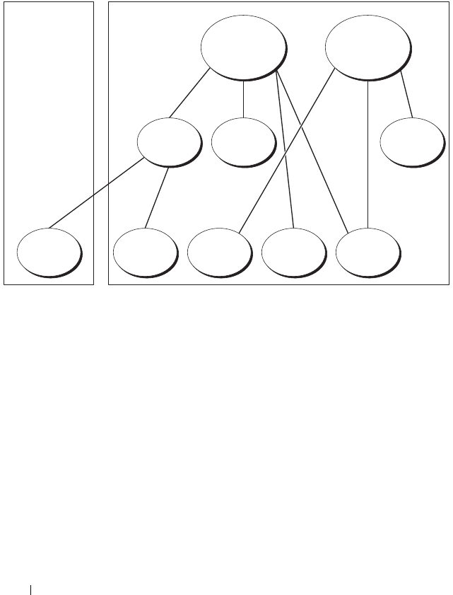
190 Using the CMC With Microsoft Active Directory
Domain1, and user2 and user 3 are in Domain2. In this scenario, configure
user1 and user 2 with administrator privileges to both CMCs and configure
user3 with login privileges to the RAC2 card.
Figure 7-3. Setting Up Active Directory Objects in Multiple Domains
To configure the objects for the multiple domain scenario:
1
Ensure that the domain forest function is in Native or Windows 2003
mode.
2
Create two Association Objects, A01 (of Universal scope) and A02, in any
domain.
Figure 7-3 shows the objects in Domain2.
3
Create two RAC Device Objects, RAC1 and RAC2, to represent the two
CMCs.
4
Create two Privilege Objects, Priv1 and Priv2, in which Priv1 has all
privileges (administrator) and Priv2 has login privilege.
5
Group user1 and user2 into Group1. The group scope of Group1 must be
Universal.
AO1 AO2
Priv2Priv1Group1
RAC2RAC1User3User2User1
Domain2Domain1

Using the CMC With Microsoft Active Directory 191
6
Add Group1 as Members in Association Object 1 (A01), Priv1 as Privilege
Objects in A01, and RAC1, RAC2 as RAC Devices in A01.
7
Add User3 as Members in Association Object 2 (A02), Priv2 as Privilege
Objects in A02, and RAC2 as RAC Devices in A02.
Configuring Extended Schema Active Directory to Access Your CMC
Before using Active Directory to access your CMC, configure the Active
Directory software and the CMC:
1
Extend the Active Directory schema (see "Extending the Active Directory
Schema" on page 191).
2
Extend the Active Directory Users and Computers Snap-In (see "Installing
the Dell Extension to the Active Directory Users and Computers Snap-In"
on page 197).
3
Add CMC users and their privileges to Active Directory (see "Adding
CMC Users and Privileges to Active Directory" on page 198).
4
Enable SSL on each of your domain controllers.
5
Configure the CMC Active Directory properties using either the CMC
Web interface or the RACADM (see "Configuring the CMC With
Extended Schema Active Directory and the Web Interface" on page 201 or
"Configuring the CMC With Extended Schema Active Directory and
RACADM" on page 203).
Extending the Active Directory Schema
Extending your Active Directory schema adds a Dell organizational unit,
schema classes and attributes, and example privileges and association objects
to the Active Directory schema. Before you extend the schema, ensure that
you have Schema Admin privilege on the Schema Master Flexible Single
Master Operation (FSMO) Role Owner of the domain forest.
You can extend your schema using one of the following methods:
• Dell Schema Extender utility
• LDIF script file
If you use the LDIF script file, the Dell organizational unit will not be added
to the schema.

192 Using the CMC With Microsoft Active Directory
The LDIF files and Dell Schema Extender are located on your Dell Systems
Management Tools and Documentation DVD in the following respective
directories:
•
<DVDdrive>:\SYSMGMT\ManagementStation\support\
OMActiveDirectory_Tools\<installation type>\LDIF Files
•
<DVDdrive>:\SYSMGMT\ManagementStation\support\
OMActiveDirectory_ Tools\<installation type>\Schema Extender
To use the LDIF files, see the instructions in the readme included in the
LDIF_Files directory. For instructions on using the Dell Schema Extender to
extend the Active Directory Schema, see "Using the Dell Schema Extender."
You can copy and run the Schema Extender or LDIF files from any location.
Using the Dell Schema Extender
NOTICE: The Dell Schema Extender uses the SchemaExtenderOem.ini file. To
ensure that the Dell Schema Extender utility functions properly, do not modify the
name of this file.
1
In the
Welcome
screen, click
Next.
2
Read and understand the warning and click
Next
.
3
Select
Use Current Log In Credentials
or enter a user name and password
with schema administrator rights.
4
Click
Next
to run the Dell Schema Extender.
5
Click
Finish
.
The schema is extended. To verify the schema extension, use the
Microsoft Management Console (MMC) and the Active Directory
Schema Snap-In to verify that the following exist:
• Classes — see Table 7-1 through Table 7-6
• Attributes — see Table 7-7
See your Microsoft documentation for more information on how to enable
and use the Active Directory Schema Snap-In the MMC.

Using the CMC With Microsoft Active Directory 193
Table 7-1. Class Definitions for Classes Added to the Active
Directory Schema
Class Name Assigned Object Identification Number (OID)
dellRacDevice 1.2.840.113556.1.8000.1280.1.1.1.1
dellAssociationObject 1.2.840.113556.1.8000.1280.1.1.1.2
dellRACPrivileges 1.2.840.113556.1.8000.1280.1.1.1.3
dellPrivileges 1.2.840.113556.1.8000.1280.1.1.1.4
dellProduct 1.2.840.113556.1.8000.1280.1.1.1.5
Table 7-2. dellRacDevice Class
OID 1.2.840.113556.1.8000.1280.1.1.1.1
Description Represents the Dell RAC device. The RAC device must be
configured as dellRacDevice in Active Directory. This configuration
enables the CMC to send Lightweight Directory Access Protocol
(LDAP) queries to Active Directory.
Class Type Structural Class
SuperClasses dellProduct
Attributes dellSchemaVersion
dellRacType
Table 7-3. dellAssociationObject Class
OID 1.2.840.113556.1.8000.1280.1.1.1.2
Description Represents the Dell Association Object. The Association Object
provides the connection between the users and the devices.
Class Type Structural Class
SuperClasses Group
Attributes dellProductMembers
dellPrivilegeMember

194 Using the CMC With Microsoft Active Directory
Table 7-4. dellRAC4Privileges Class
OID 1.2.840.113556.1.8000.1280.1.1.1.3
Description Defines Authorization Rights (privileges) for the CMC device.
Class Type Auxiliary Class
SuperClasses None
Attributes dellIsLoginUser
dellIsCardConfigAdmin
dellIsUserConfigAdmin
dellIsLogClearAdmin
dellIsServerResetUser
dellIsTestAlertUser
dellIsDebugCommandAdmin
dellPermissionMask1
dellPermissionMask2
Table 7-5. dellPrivileges Class
OID 1.2.840.113556.1.8000.1280.1.1.1.4
Description Container Class for the Dell Privileges (Authorization Rights).
Class Type Structural Class
SuperClasses User
Attributes dellRAC4Privileges
Table 7-6. dellProduct Class
OID 1.2.840.113556.1.8000.1280.1.1.1.5
Description The main class from which all Dell products are derived.
Class Type Structural Class
SuperClasses Computer
Attributes dellAssociationMembers

Using the CMC With Microsoft Active Directory 195
Table 7-7. List of Attributes Added to the Active Directory Schema
Assigned OID/Syntax Object Identifier Single Valued
Attribute: dellPrivilegeMember
Description: List of dellPrivilege objects that belong to this
attribute.
OID: 1.2.840.113556.1.8000.1280.1.1.2.1
Distinguished Name: (LDAPTYPE_DN
1.3.6.1.4.1.1466.115.121.1.12)
FALSE
Attribute: dellProductMembers
Description: List of dellRacDevices objects that belong to this role.
This attribute is the forward link to the dellAssociationMembers
backward link.
Link ID: 12070
OID: 1.2.840.113556.1.8000.1280.1.1.2.2
Distinguished Name: (LDAPTYPE_DN
1.3.6.1.4.1.1466.115.121.1.12)
FALSE
Attribute: dellIsCardConfigAdmin
Description: TRUE if the user has Card Configuration rights on the device.
OID: 1.2.840.113556.1.8000.1280.1.1.2.4
Boolean (LDAPTYPE_BOOLEAN 1.3.6.1.4.1.1466.115.121.1.7)
TRUE
Attribute: dellIsLoginUser
Description: TRUE if the user has Login rights on the device.
OID: 1.2.840.113556.1.8000.1280.1.1.2.3
Boolean (LDAPTYPE_BOOLEAN 1.3.6.1.4.1.1466.115.121.1.7)
TRUE
Attribute: dellIsCardConfigAdmin
Description: TRUE if the user has Card Configuration rights on the
device.
OID: 1.2.840.113556.1.8000.1280.1.1.2.4
Boolean (LDAPTYPE_BOOLEAN 1.3.6.1.4.1.1466.115.121.1.7)
TRUE

196 Using the CMC With Microsoft Active Directory
Attribute: dellIsUserConfigAdmin
Description: TRUE if the user has User Configuration
Administrator rights on the device.
OID: 1.2.840.113556.1.8000.1280.1.1.2.5
Boolean (LDAPTYPE_BOOLEAN 1.3.6.1.4.1.1466.115.121.1.7)
TRUE
Attribute: delIsLogClearAdmin
Description: TRUE if the user has Clear Logs Administrator rights
on the device.
OID: 1.2.840.113556.1.8000.1280.1.1.2.6
Boolean (LDAPTYPE_BOOLEAN 1.3.6.1.4.1.1466.115.121.1.7)
TRUE
Attribute: dellIsServerResetUser
Description: TRUE if the user has Server Reset rights on the device.
OID: 1.2.840.113556.1.8000.1280.1.1.2.7
Boolean (LDAPTYPE_BOOLEAN 1.3.6.1.4.1.1466.115.121.1.7)
TRUE
Attribute: dellIsTestAlertUser
Description: TRUE if the user has Test Alert User rights on the device.
OID: 1.2.840.113556.1.8000.1280.1.1.2.10
Boolean (LDAPTYPE_BOOLEAN 1.3.6.1.4.1.1466.115.121.1.7)
TRUE
Attribute: dellIsDebugCommandAdmin
Description: TRUE if the user has Debug Command Admin rights
on the device.
OID: 1.2.840.113556.1.8000.1280.1.1.2.11
Boolean (LDAPTYPE_BOOLEAN 1.3.6.1.4.1.1466.115.121.1.7)
TRUE
Attribute: dellSchemaVersion
Description: The Current Schema Version is used to update the schema.
OID: 1.2.840.113556.1.8000.1280.1.1.2.12
Case Ignore String(LDAPTYPE_CASEIGNORESTRING
1.2.840.113556.1.4.905)
TRUE
Table 7-7. List of Attributes Added to the Active Directory Schema (continued)
Assigned OID/Syntax Object Identifier Single Valued

Using the CMC With Microsoft Active Directory 197
Installing the Dell Extension to the Active Directory Users and
Computers Snap-In
When you extend the schema in Active Directory, you must also extend the
Active Directory Users and Computers Snap-In so the administrator can
manage RAC (CMC) devices, Users and User Groups, RAC Associations, and
RAC Privileges.
When you install your systems management software using the Dell Systems
Management Tools and Documentation DVD, you can extend the Snap-In by
selecting the Dell Extension to the Active Directory User’s and Computers
Snap-In option during the installation procedure. See the Dell OpenManage
Software Quick Installation Guide for additional instructions about installing
systems management software.
Attribute: dellRacType
Description: This attribute is the Current Rac Type for the
dellRacDevice object and the backward link to the
dellAssociationObjectMembers forward link.
OID: 1.2.840.113556.1.8000.1280.1.1.2.13
Case Ignore String(LDAPTYPE_CASEIGNORESTRING
1.2.840.113556.1.4.905)
TRUE
Attribute: dellAssociationMembers
Description: List of dellAssociationObjectMembers that belong to
this Product. This attribute is the backward link to the
dellProductMembers Linked attribute.
Link ID: 12071
OID: 1.2.840.113556.1.8000.1280.1.1.2.14
Distinguished Name (LDAPTYPE_DN
1.3.6.1.4.1.1466.115.121.1.12)
FALSE
Attribute: dellPermissionsMask1
OID: 1.2.840.113556.1.8000.1280.1.6.2.1 Integer (LDAPTYPE_INTEGER)
Attribute: dellPermissionsMask2
OID: 1.2.840.113556.1.8000.1280.1.6.2.2 Integer (LDAPTYPE_INTEGER)
Table 7-7. List of Attributes Added to the Active Directory Schema (continued)
Assigned OID/Syntax Object Identifier Single Valued

198 Using the CMC With Microsoft Active Directory
For more information about the Active Directory User’s and Computers
Snap-In, see your Microsoft documentation.
Installing the Administrator Pack
You must install the Administrator Pack on each system that is managing the
Active Directory CMC Objects. If you do not install the Administrator Pack,
you cannot view the Dell RAC Object in the container.
Opening the Active Directory Users and Computers Snap-In
To open the Active Directory Users and Computers Snap-In:
1
If you are logged into the domain controller, click
Start
Admin Tools
→
Active Directory Users and Computers
.
If you are not logged into the domain controller, you must have the
appropriate Microsoft Administrator Pack installed on your local system.
To install this Administrator Pack, click
Start
→
Run
, type
MMC
, and press
<Enter>.
The Microsoft Management Console (MMC) appears.
2
In the
Console 1
window, click
File
(or
Console
on systems running
Windows 2000).
3
Click
Add/Remove Snap-in
.
4
Select the
Active Directory Users and Computers
Snap-In and click
Add
.
5
Click
Close
and click
OK
.
Adding CMC Users and Privileges to Active Directory
Using the Dell-extended Active Directory Users and Computers Snap-In, you
can add CMC users and privileges by creating RAC, Association, and Privilege
objects. To add each object type, you will:
1
Create a RAC device Object.
2
Create a Privilege Object.
3
Create an Association Object.
4
Add objects to an Association Object.

Using the CMC With Microsoft Active Directory 199
Creating a RAC Device Object
1
In the MMC
Console Root
window, right-click a container.
2
Select
New
→
Dell RAC Object
.
The
New Object
window appears.
3
Type a name for the new object. The name must be identical to the CMC
Name that you will type in step 8a of "Configuring the CMC With
Extended Schema Active Directory and the Web Interface" on page 201.
4
Select
RAC Device Object
.
5
Click
OK
.
Creating a Privilege Object
NOTE: A Privilege Object must be created in the same domain as the related
Association Object.
1
In the
Console Root
(MMC) window, right-click a container.
2
Select
New
→
Dell RAC Object
.
The
New Object
window appears.
3
Type a name for the new object.
4
Select
Privilege Object
.
5
Click
OK
.
6
Right-click the privilege object that you created, and select
Properties
.
7
Click the
RAC Privileges
tab and select the privileges that you want the
user to have. For more information about CMC user privileges, see "User
Types" on page 121.
Creating an Association Object
The Association Object is derived from a Group and must contain a Group
Type. The Association Scope specifies the Security Group Type for the
Association Object. When you create an Association Object, choose the
Association Scope that applies to the type of objects you intend to add.

200 Using the CMC With Microsoft Active Directory
For example, if you select Universal, the association objects are only available
when the Active Directory Domain is functioning in Native Mode or above.
1
In the
Console Root
(MMC) window, right-click a container.
2
Select
New
→
Dell RAC Object
.
This opens the
New Object
window.
3
Type a name for the new object.
4
Select
Association Object
.
5
Select the scope for the
Association Object
.
6
Click
OK
.
Adding Objects to an Association Object
Using the Association Object Properties window, you can associate users or
user groups, privilege objects, and RAC devices or RAC device groups. If your
system is running Windows 2000 mode or higher, use Universal Groups to
span domains with your user or RAC objects.
You can add groups of Users and RAC devices. The procedure for creating
Dell-related groups and non-Dell-related groups is identical.
Adding Users or User Groups
1
Right-click the
Association Object
and select
Properties
.
2
Select the
Users
tab and click
Add
.
3
Type the user or User Group name and click
OK
.
Click the Privilege Object tab to add the privilege object to the association
that defines the user’s or user group’s privileges when authenticating to a
RAC device. Only one privilege object can be added to an Association Object.
Adding Privileges
1
Select the
Privileges Object
tab and click
Add
.
2
Type the Privilege Object name and click
OK
.
Click the Products tab to add one or more RAC devices to the association.
The associated devices specify the RAC devices connected to the network
that are available for the defined users or user groups. Multiple RAC devices
can be added to an Association Object.

Using the CMC With Microsoft Active Directory 201
Adding RAC Devices or RAC Device Groups
To add RAC devices or RAC device groups:
1
Select the
Products
tab and click
Add.
2
Type the RAC device or RAC device group name and click
OK
.
3
In the
Properties
window, click
Apply
and click
OK
.
Configuring the CMC With Extended Schema Active Directory and the
Web Interface
1
Log in to the CMC Web interface.
2
Select
Chassis
in the system tree.
3
Click the
Network/Security
tab, and then click the
Active Directory
sub-
tab. The
Active Directory Main Menu
page appears.
4
Select the
Configure radio button
, and then click
Next
. The
Active
Directory Configuration and Management
page appears.
5
In the
Common Setting
s section:
a
Select the
Enable Active Directory
check box so that it is checked.
b
Ty p e th e
Root Domain Name
. The
Root Domain Name
is the fully
qualified root domain name for the forest.
NOTE: The Root domain name must be a valid domain name using the x.y
naming convention, where x is a 1–256 character ASCII string with no spaces
between characters, and y is a valid domain type such as com, edu, gov, int,
mil, net, or org.
c
Ty p e th e
Timeout
time in seconds.
Configuration range:
15–300 seconds.
Default:
90 seconds
6
Optional:
If you want the directed call to search the domain controller and
global catalog, select the
Search AD Server to search (Optional)
check
box, then:
a
In the
Domain Controller
text field, type the server where your Active
Directory service is installed.
b
In the
Global Catalog
text field, type the location of the global
catalog on the Active Directory domain controller. The global catalog
provides a resource for searching an Active Directory forest.

202 Using the CMC With Microsoft Active Directory
7
Select the
Use Extended Schema
radio button in the
Active Directory
Schema Selection
area.
8
In the
Extended Schema Settings
section:
a
Typ e t he
CMC Name
. The
CMC Name
uniquely identifies the CMC
card in Active Directory. The
CMC Name
must be the same as the
common name of the new CMC object you created in your Domain
Controller. The
CMC Name
must be a 1–256 character ASCII string
with no spaces between characters.
b
Typ e t he
CMC Domain Name
(example:
cmc.com
). The
CMC
Domain Name
is the DNS name (string) of the domain where the
Active Directory CMC object resides. The name must be a valid
domain name consisting of
x.y
, where
x
is a 1–256 character ASCII
string with no spaces between characters, and
y
is a valid domain type
such as com, edu, gov, int, mil, net, or org.
9
Click
Apply
to save your settings.
NOTE: You must apply your settings before continuing to the next step, in
which you navigate to another page. If you do not apply the settings, you will
lose the settings you entered when you navigate to the next page.
10
Click
Go Back To Active Directory Main Menu
.
11
Select the
Upload AD Certificate
radio button, and then click
Next
. The
Certificate Upload
page appears.
12
Type the file path of the certificate in the text field, or click
Browse
to
select the certificate file.
NOTE: The File Path value displays the relative file path of the certificate you
are uploading. You must type the absolute file path, which includes the full
path and the complete file name and file extension.
The SSL certificates for the domain controller must be signed by the root
certificate authority. The root certificate authority-signed certificate must
be available on the management station accessing the CMC.
13
Click
Apply
. The CMC Web server automatically restarts after you click
Apply
.
14
Log back in to the CMC Web interface.
15
Select
Chassis
in the system tree, click the
Network/Security
tab, then
click the
Network
sub-tab. The
Network Configuration
page appears.

Using the CMC With Microsoft Active Directory 203
16
If
Use DHCP (for NIC IP Address)
is enabled (checked), do one of the
following:
• Select
Use DHCP to Obtain DNS Server Addresses
to enable the
DNS server addresses to be obtained automatically by the DHCP
server., or
• Manually configure a DNS server IP address by leaving the
Use DHCP
to Obtain DNS Server Addresses
check box unchecked and then
typing your primary and alternate DNS server IP addresses in the
fields provided.
17
Click
Apply Changes
.
The CMC Extended Schema Active Directory feature configuration is
complete.
Configuring the CMC With Extended Schema Active Directory and
RACADM
Using the following commands to configure the CMC Active Directory
Feature with Extended Schema using the RACADM CLI tool instead of the
Web interface.
1
Open a Telnet/SSH text console to the CMC, log in, and type:
racadm config -g cfgActiveDirectory -o cfgADEnable
1
racadm config -g cfgActiveDirectory -o cfgADType 1
racadm config -g cfgActiveDirectory -o
cfgADRacDomain <
fully qualified CMC domain name
>
racadm config -g cfgActiveDirectory -o
cfgADRootDomain <
fully qualified root domain name
>
racadm config -g cfgActiveDirectory -o
cfgADRacName <
CMC common name
>
racadm sslcertupload -t 0x2 -f <
ADS root CA
certificate
> -r
racadm sslcertdownload -t 0x1 -f <
CMC SSL
certificate
>

204 Using the CMC With Microsoft Active Directory
Optional:
If you want to specify an LDAP or Global Catalog server instead
of using the servers returned by the DNS server to search for a user name,
type the following command to enable the
Specify Server
option:
racadm config -g cfgActiveDirectory -o
cfgADSpecifyServerEnable 1
NOTE: When you use the Specify Server option, the host name in the
certificate authority-signed certificate is not matched against the name of the
specified server. This is particularly useful if you are a CMC administrator,
because it enables you to enter a host name as well as an IP address.
After you enable the
Specify Server
option, you can specify an LDAP
server and global catalog with IP addresses or fully qualified domain names
(FQDNs) of the servers. The FQDNs consist of the host names and the
domain names of the servers.
To specify an LDAP server, type:
racadm config -g cfgActiveDirectory -o
cfgADDomainController <AD domain controller IP
address>
To specify a Global Catalog server, type:
racadm config -g cfgActiveDirectory -o
cfgADGlobalCatalog <AD global catalog IP address>
NOTE: Setting the IP address as 0.0.0.0 disables the CMC from searching for a
server.
NOTE: You can specify a list of LDAP or global catalog servers separated by
commas. The CMC allows you to specify up to three IP addresses or host
names.
NOTE: LDAP or LDAPs that are not correctly configured for all domains and
applications may produce unexpected results during the functioning of the
existing applications/domains.
2
Specify a DNS server using one of the following options:
• If DHCP is enabled on the CMC and you want to use the DNS
address obtained automatically by the DHCP server, type the
following command:
racadm config -g cfgLanNetworking -o
cfgDNSServersFromDHCP 1

Using the CMC With Microsoft Active Directory 205
• If DHCP is disabled on the CMC, or if DHCP is enabled but you want
to specify your DNS IP address manually, type following commands:
racadm config -g cfgLanNetworking -o
cfgDNSServersFromDHCP 0
racadm config -g cfgLanNetworking -o
cfgDNSServer1
<primary DNS IP address>
racadm config -g cfgLanNetworking -o
cfgDNSServer2
<secondary DNS IP address>
The Extended Schema feature configuration is complete.
Standard Schema Active Directory Overview
Using standard schema for Active Directory integration requires
configuration on both Active Directory and the CMC.
On the Active Directory side, a standard group object is used as a role group.
A user who has CMC access will be a member of the role group.
In order to give this user access to a specific CMC card, the role group name
and its domain name need to be configured on the specific CMC card. Unlike
the extended schema solution, the role and the privilege level is defined on
each CMC card, not in the Active Directory. Up to five role groups can be
configured and defined in each CMC. Table 5-10 shows the privileges level of
the role groups and Table 7-8 shows the default role group settings.
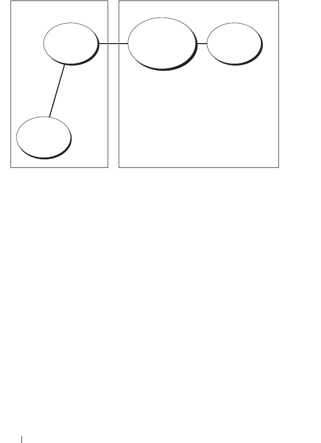
206 Using the CMC With Microsoft Active Directory
Figure 7-4. Configuration of CMC with Active Directory and Standard Schema
Role
Group
Role
Group Name
and Domain
Name
Role
Definition
User
Configuration on Active
Directory Side
Configuration on
CMC Side

Using the CMC With Microsoft Active Directory 207
Table 7-8. Default Role Group Privileges
Role Group Default
Privilege
Level
Permissions Granted Bit Mask
1None
•CMC Login User
• Chassis Configuration
Administrator
• User Configuration Administrator
• Clear Logs Administrator
• Chassis Control Administrator
(Power Commands)
• Super User
• Server Administrator
• Test Alert User
• Debug Command User
• Fabric A Administrator
• Fabric B Administrator
• Fabric C Administrator
0x00000fff
2None
•CMC Login User
• Clear Logs Administrator
• Chassis Control Administrator
(Power Commands)
• Server Administrator
• Test Alert User
• Fabric A Administrator
• Fabric B Administrator
• Fabric C Administrator
0x000000f9
3 None CMC Login User 0x00000001
4 None No assigned permissions 0x00000000
5 None No assigned permissions 0x00000000

208 Using the CMC With Microsoft Active Directory
NOTE: The bit mask values are used only when setting Standard Schema with the
RACADM.
NOTE: For more information about user privileges, see "User Types" on page 120.
There are two ways to enable Standard Schema Active Directory:
• With the CMC Web interface. See "Configuring the CMC With Standard
Schema Active Directory and Web Interface" on page 208.
• With the RACADM CLI tool. See "Configuring the CMC With Standard
Schema Active Directory and RACADM" on page 211.
Configuring Standard Schema Active Directory to Access Your CMC
You need to perform the following steps to configure the Active Directory
before an Active Directory user can access the CMC:
1
On an Active Directory server (domain controller), open the Active
Directory Users and Computers Snap-in.
2
Create a group or select an existing group. The name of the group and the
name of this domain will need to be configured on the CMC either with
the Web interface or RACADM.
For more information, see "Configuring the CMC With Standard Schema
Active Directory and Web Interface" on page 208 or "Configuring the
CMC With Standard Schema Active Directory and RACADM" on
page 211.
3
Add the Active Directory user as a member of the Active Directory group
to access the CMC.
Configuring the CMC With Standard Schema Active Directory and Web
Interface
1
Log in to the CMC Web interface.
2
Select
Chassis
in the system tree.
3
Click the
Network/Security
tab, and then click the
Active Directory
sub-
tab. The
Active Directory Main Menu
page appears.
4
Select the
Configure option,
and then click
Next
. The
Active Directory
Configuration and Management
page appears.

Using the CMC With Microsoft Active Directory 209
5
In the
Common Settings
section:
a
Select the
Enable Active Directory
check box.
b
Ty p e th e
ROOT Domain Name
. The
ROOT Domain Name
is the
fully qualified root domain name for the forest.
NOTE: The ROOT domain name must be a valid domain name using the x.y
naming convention, where x is a 1–256 character ASCII string with no spaces
between characters, and y is a valid domain type such as com, edu, gov, int,
mil, net, or org.
c
Ty p e th e
Timeout
time in seconds.
Configuration range:
15–300 seconds.
Default:
90 seconds
6
Optional:
If you want the directed call to search the domain controller and
global catalog, select the
Search AD Server to search (Optional)
check
box, then:
a
In the
Domain Controller
text field, type the server where your Active
Directory service is installed.
b
In the
Global Catalog
text field, type the location of the global
catalog on the Active Directory domain controller. The global catalog
provides a resource for searching an Active Directory forest.
7
Click
Use Standard Schema
in the Active Directory Schema Selection
section.
8
Click
Apply
to save your settings.
NOTE: You must apply your settings before continuing to the next step, in
which you navigate to another page. If you do not apply the settings, you will
lose the settings you entered when you navigate to the next page.
9
In the
Standard Schema Settings
section, click a
Role Group
. The
Configure Role Group
page appears.
10
Ty p e th e
Group Name
. The group name identifies the role group in the
Active Directory associated with the CMC card.
11
Ty p e th e
Group Domain
. The
Group Domain
is the fully qualified root
domain name for the forest.
12
In the
Role Group Privileges
page, select privileges for the group.
If you modify any of the privileges, the existing
Role Group Privilege
(Administrator, Power User, or Guest User) will change to either the
Custom group or the appropriate Role Group Privilege. See Table 5-10.

210 Using the CMC With Microsoft Active Directory
13
Click
Apply
to save the Role Group settings.
14
Click
Go Back To Active Directory Configuration and Management
.
15
Click
Go Back To Active Directory Main Menu
.
16
Upload your domain forest Root certificate authority-signed certificate
into the CMC.
a
Select the
Upload Active Directory CA Certificat
e check box and
then click
Next
.
b
In the
Certificate Upload
page, type the file path of the certificate or
browse to the certificate file.
NOTE: The File Path value displays the relative file path of the certificate you
are uploading. You must type the absolute file path, which includes the full
path and the complete file name and file extension.
The SSL certificates for the domain controllers must be signed by the
root certificate authority-signed certificate. The root certificate
authority-signed certificate must be available on the management
station accessing the CMC.
c
Click
Apply
. The CMC Web server automatically restarts after you
click
Apply
.
17
Log out and then log in to the CMC to complete the CMC Active
Directory feature configuration.
18
Select
Chassis
in the system tree.
19
Click the
Network/Security
tab.
20
Click the
Network
sub-tab. The
Network Configuration
page appears.
21
If
Use DHCP (for NIC IP Address)
is selected under
Network Settings
,
select
Use DHCP to obtain DNS server address
.
To manually input a DNS server IP address, deselect
Use DHCP to obtain
DNS server addresses
and type your primary and alternate DNS server IP
addresses.
22
Click
Apply Changes
.
The CMC Standard Schema Active Directory feature configuration is
complete.

Using the CMC With Microsoft Active Directory 211
Configuring the CMC With Standard Schema Active Directory and
RACADM
To configure the CMC Active Directory Feature with Standard Schema using
the RACADM CLI, use the following commands:
1
Open a Telnet/SSH text console to the CMC, log in, and type:
racadm config -g cfgActiveDirectory -o cfgADEnable
1
racadm config -g cfgActiveDirectory -o cfgADType 2
racadm config -g cfgActiveDirectory -o
cfgADRootDomain <
fully qualified root domain name
>
racadm config -g cfgStandardSchema -i <index> -o
cfgSSADRoleGroupName <
common name of the role
group
>
racadm config -g cfgStandardSchema -i <index> -o
cfgSSADRoleGroupDomain <
fully qualified domain
name
>
racadm config -g cfgStandardSchema -i <index> -o
cfgSSADRoleGroupPrivilege <Bit mask number for
specific user permissions>
racadm sslcertupload -t 0x2 -f <
ADS root CA
certificate
>
racadm sslcertdownload -t 0x1 -f <
RAC SSL
certificate
>
NOTE: For bit mask number values, see "Bit Masks for User Privileges" on
page 394.
2
Specify a DNS server using one of the following options:
• If DHCP is enabled on the CMC and you want to use the DNS
address obtained automatically by the DHCP server, type the
following command:
racadm config -g cfgLanNetworking -o
cfgDNSServersFromDHCP 1

212 Using the CMC With Microsoft Active Directory
• If DHCP is disabled on the CMC or you want manually to input your
DNS IP address, type the following commands:
racadm config -g cfgLanNetworking -o
cfgDNSServersFromDHCP 0
racadm config -g cfgLanNetworking -o
cfgDNSServer1 <
primary DNS IP address
>
racadm config -g cfgLanNetworking -o
cfgDNSServer2 <secondary DNS IP address
>
Frequently Asked Questions
Table 7-9 lists frequently asked questions and answers about using Active
Directory with the CMC.
Table 7-9. Using CMC With Active Directory: Frequently Asked Questions
Question Answer
Can I log into the CMC using Active
Directory across multiple trees?
Yes. The CMC’s Active Directory querying
algorithm supports multiple trees in a single
forest.
Does the login to the CMC using
Active Directory work in mixed
mode (that is, the domain
controllers in the forest run different
operating systems, such as Microsoft
Windows® 2000 or Windows
Server® 2003)?
Yes. In mixed mode, all objects used by the
CMC querying process (among user, RAC
Device Object, and Association Object) must
be in the same domain.
The Dell-extended Active Directory Users and
Computers Snap-In checks the mode and
limits users in order to create objects across
domains if in mixed mode.
Does using the CMC with Active
Directory support multiple domain
environments?
Yes. The domain forest function level must be
in Native mode or Windows 2003 mode. In
addition, the groups among Association
Object, RAC user objects, and RAC Device
Objects (including Association Object) must
be universal groups.

Using the CMC With Microsoft Active Directory 213
Can these Dell-extended objects
(Dell Association Object, Dell RAC
Device, and Dell Privilege Object)
be in different domains?
The Association Object and the Privilege
Object must be in the same domain. The Dell-
extended Active Directory Users and
Computers Snap-In forces you to create these
two objects in the same domain. Other objects
can be in different domains.
Are there any restrictions on Domain
Controller SSL configuration?
Yes. All SSL certificates for Active Directory
servers in the forest must be signed by the
same root certificate authority-signed
certificate, because CMC only allows you to
upload one trusted certificate authority-signed
SSL certificate.
I created and uploaded a new RAC
certificate and now the Web
interface does not launch.
If you use Microsoft Certificate Services to
generate the RAC certificate, you may have
inadvertently chose User Certificate instead of
Web Certificate when creating the certificate.
To recover, generate a CSR, and then create a
new Web certificate from Microsoft
Certificate Services and upload it using the
using the following RACADM commands:
racadm sslcsrgen [-g] [-u]
[-f {filename}]
racadm sslcertupload -t 1 -f
{web_sslcert}
Table 7-9. Using CMC With Active Directory: Frequently Asked Questions (continued)
Question Answer

214 Using the CMC With Microsoft Active Directory
What can I do if I cannot log into
the CMC using Active Directory
authentication? How do I
troubleshoot the issue?
1
Ensure that you use the correct user domain
name during a login and not the NetBIOS
name.
2
If you have a local CMC user account, log
into the CMC using your local credentials.
After you are logged in, perform the following
steps:
a
Ensure that you have checked the
Enable
Active Directory
check box on the CMC
Active Directory configuration page.
b
Ensure that the DNS setting is correct on
the CMC Networking configuration page.
c
Ensure that you have uploaded the Active
Directory certificate from your Active
Directory root certificate authority-signed
certificate to the CMC.
d
Check the Domain Controller SSL
certificates to ensure that they have not
expired.
e
Ensure that your
CMC Name
,
Root
Domain Name
, and
CMC Domain Name
match your Active Directory environment
configuration.
f
Ensure that the CMC password has a
maximum of 127 characters. While the
CMC can support passwords of up to 256
characters, Active Directory only supports
passwords that have a maximum length of
127 characters.
Table 7-9. Using CMC With Active Directory: Frequently Asked Questions (continued)
Question Answer

Power Management 215
Power Management
Overview
The M1000e chassis ships with either three power supply units (PSUs) or six,
the maximum. If your chassis has three PSUs, you can add up to three more.
The PSUs supply power to the chassis and all the modules in the chassis:
CMC, IOM, iKVM, fans, front panel LCD and servers. The CMC manages
the power budget for all the chassis modules.
For AC redundancy to work in a six-PSU configuration, the three PSUs on the
left must connect to one AC power grid while the three on the right connect
to another. AC Redundancy is not available in a three-PSU configuration.
Each PSU helps the CMC manage the power distribution to the modules.
Power Budgeting for Hardware Modules
The CMC allocates power to the modules in the M1000e chassis dynamically
as they are installed into the chassis.
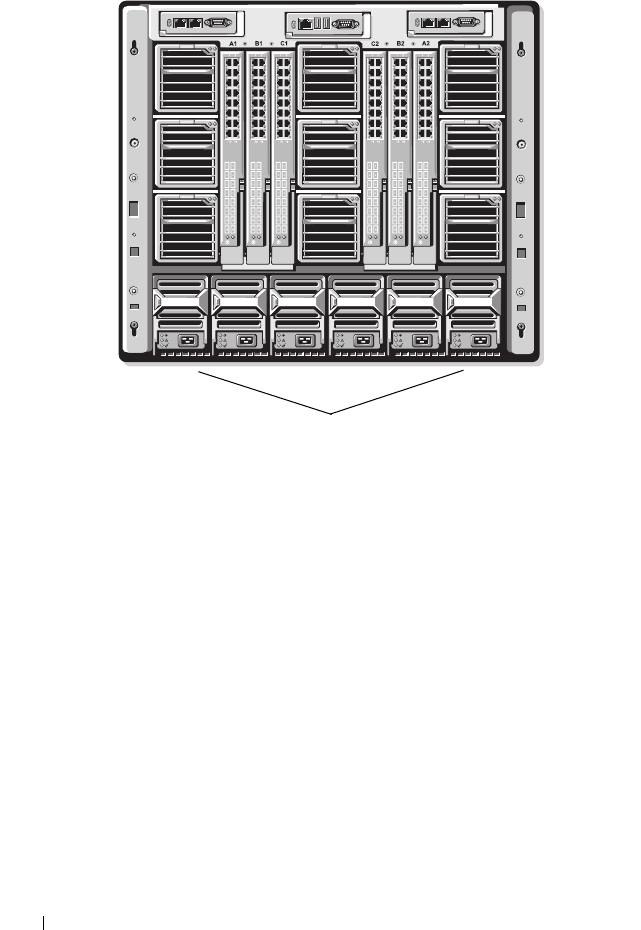
216 Power Management
Figure 8-1. Chassis With Six-PSU Configuration
Dynamic PSU Engagement
Dynamic PSU engagement is a configurable option that enables the CMC to
conserve power by powering-off unused PSUs and keeping them in Standby
mode in case more power is required. This saves power by increasing the
utilization of the PSUs that remain active so that they are used more
efficiently.
Factors that cause a single or set of PSUs to change to Standby mode include
the following:
• Module population
• The number of PSUs in the chassis
• The redundancy policy
• The capabilities and maximum efficiency point of the PSU configuration
PSUs

Power Management 217
To maintain optimal efficiency, the CMC uses this information to determine
how many PSUs are required to power a given configuration and place excess
PSUs on standby. If new modules are installed, the CMC may, depending on
need and optimization, turn on new supplies.
Redundancy Policies
The redundancy policy is a configurable set of properties that determine how
the CMC manages power to the chassis. The following redundancy policies
are configurable with or without dynamic PSU engagement:
• AC Redundancy
• Power Supply Redundancy
• No Redundancy
You can select and configure a redundancy policy or use the default
redundancy policy for your chassis. The default redundancy configuration for
your chassis depends on how many PSUs are configured for it, as shown in
Tabl e 8 -1 .
AC Redundancy
For AC Redundancy mode to operate at optimal power, you must have six
PSUs in your chassis. You can set your chassis to operate in AC Redundancy
mode with fewer than six PSUs, but it will operate in a degraded state.
In AC Redundancy mode, all six PSUs will be active. The three PSUs on the
left must connect to one AC power grid, while the three PSUs on the right
connect to another AC power grid.
NOTICE: To avoid a system failure and for AC Redundancy to work effectively, you
must ensure that each set of PSUs is connected to a separate AC grid.
In case one AC grid fails, the three PSUs on the functioning AC grid take over
without interruption to the servers or infrastructure.
Table 8-1. Default Redundancy Configuration
PSU Configuration Default Redundancy
Policy
Default Dynamic PSU Engagement
Setting
Six PSUs AC Redundancy Disabled
Three PSUs No Redundancy Disabled

218 Power Management
NOTICE: In AC Redundancy mode, a difference in the number of PSUs between the
two AC grids (for example, three PSUs on one AC grid and two on the other AC grid)
will cause a degradation in the redundancy.
Power Supply Redundancy
The capacity of a PSU in the chassis is kept as a spare, ensuring that a failure
of any one PSU will not cause the servers or chassis to power-down. Power
Supply Redundancy mode requires four PSUs to operate correctly; any
additional PSUs will not be utilized. Failure of two PSUs may cause the
servers in the chassis to power down.
No Redundancy
Power from up to three PSUs is used to power on the entire chassis.
NOTICE: The No Redundancy mode uses only three PSUs without a backup.
Failure of one of the three PSUs being used could cause servers to lose power and
data.
Power Conservation and Power Budget Changes
The CMC performs power conservation when the user-configured maximum
power limit is reached. When the demand for power exceeds the power limit
you have set, the CMC reduces power to servers you assign a lower priority to
free power for higher priority servers and other modules in the chassis.
If all or multiple slots in the chassis are configured with the same priority
level, the CMC decreases power to servers by increasing slot number order.
For example, if the servers in slots 1 and 2 have the same priority level, the
power for the server in slot 1 is decreased before that of the server in slot 2.
NOTE: You can assign a priority level to each of the servers in the chassis by giving
each server a number from 1 through 9 inclusive. The default priority level for all
servers is 1. The lower the number, the higher the priority level. For instructions on
assigning server priority levels, see "Using RACADM" on page 237.
PSU Failure With a No Redundancy Policy
The CMC decreases power to servers when an insufficient power event
occurs, such as a PSU failure. After decreasing power on servers, the CMC re-
evaluates the power needs of the chassis. Power for higher priority servers is
restored incrementally while power needs remain within the power budget.
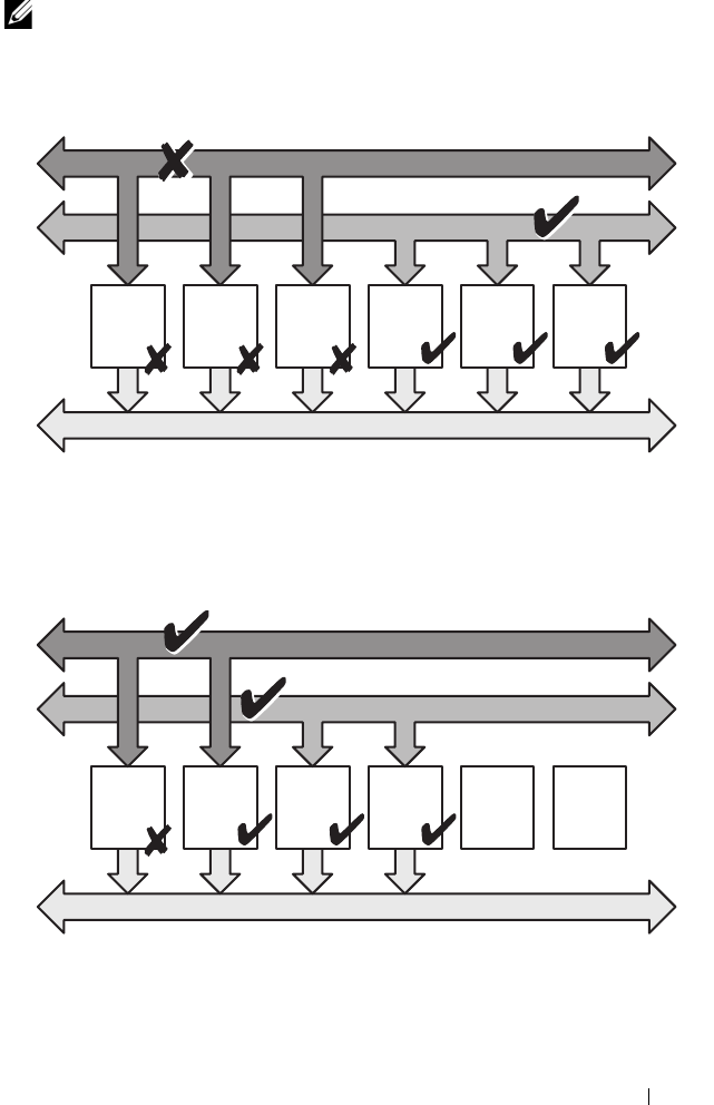
Power Management 219
NOTE: To set the redundancy policy, see "Configuring Power Budget and
Redundancy" on page 233.
Figure 8-2. AC Redundancy (top), and Power Supply Redundancy (bottom)
Power
Supply
#1
Power
Supply
#2
Power
Supply
#3
Power
Supply
#4
Power
Supply
#5
Power
Supply
#6
Power Grid #1
Power Grid #2
Chassis DC Power Bus
Dual Power Grid:
Protects against failure to an AC grid
Power
Supply
#1
Power
Supply
#2
Power
Supply
#3
Power
Supply
#4
Empty
Slot
#5
Empty
Slot
#6
Power Grid #1
Power Grid #2
Chassis DC Power Bus
Dual or Single Power Grid:
Power Supply Redundancy protects against failure
of a single power supply.
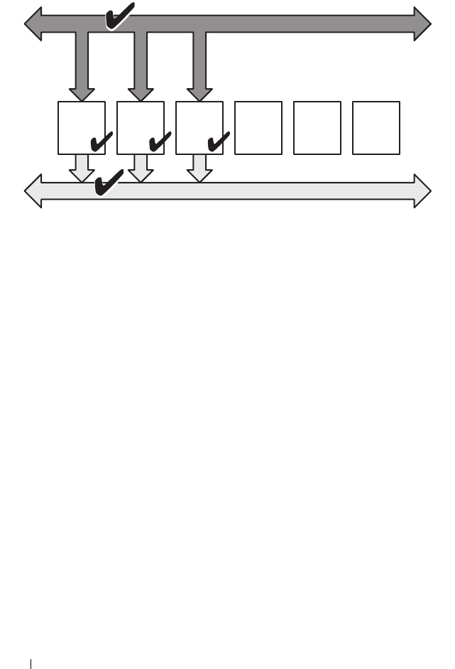
220 Power Management
Figure 8-3. No Redundancy
New Server Engagement Policy
When a new server is powered on, the CMC may need to decrease power to
lower priority servers to allow more power for the new server if adding the new
server exceeds the power available for the system. This could happen if the
administrator has configured a power limit for the chassis that is below what
would be required for full power allocation to the servers, or if insufficient
power is available for the worst-case power need of all servers in the chassis. If
enough power cannot be freed by reducing the allocated power of the lower
priority servers, the new server may not be allowed to power up.
The highest amount of sustained power required to run the chassis and all of
the servers, including the new one, at full power is the worst-case power
requirement. If that amount of power is available, then no servers are
allocated power that is less than the worst-case power needed and the new
server is allowed to power up.
If the worst-case power requirement cannot be met, power is reduced to the
lower priority servers until enough power is freed to power up the new server.
• If enough power cannot be freed by reducing power to the existing servers,
the new server is not allowed to power up.
Power
Supply
#1
Power
Supply
#2
Power
Supply
#3
Empty
Slot
#4
Empty
Slot
#5
Empty
Slot
#6
Power Grid #1
Chassis DC Power Bus
Single Power Grid:
No protection against grid or power supply failure

Power Management 221
• If enough power is freed by reducing power to the existing servers, the
freed power is allocated to the new server and the server is allowed to
power up.
Table 8-2 describes the actions taken by the CMC when a new server is
powered on in the scenario described above.
Table 8-3 describes the firmware response to a PSU power down or removal as
it applies to various PSU redundancy configurations.
Table 8-2. CMC Response When a Server Power-On is Attempted
Worst Case Power
is Available
CMC Response Server
Power On
Yes No power conservation is required Allowed
No Perform power conservation:
• Power required for new server is available
Allowed
• Power required for new server is not available
Disallowed
Table 8-3. Chassis Impact from PSU Failure or Removal
PSU Configuration Dynamic PSU
Engagement
Firmware Response
AC Redundancy Disabled User alerted of loss of AC Redundancy.
Power Supply
Redundancy
Disabled User alerted of loss of Power Supply
Redundancy.
No Redundancy Disabled Decrease power to low priority servers, if
needed.
AC Redundancy Enabled User alerted of loss of AC Redundancy. PSUs
in standby mode (if any) are turned on to
compensate for power budget lost from the
PSU failure or removal.
Power Supply
Redundancy
Enabled User alerted of loss of Power Supply
Redundancy. PSUs in standby mode (if any)
are turned on to compensate for power budget
lost from PSU failure or removal.

222 Power Management
PSU Removals With a No Redundancy Policy
The CMC may begin conserving power when a user removes a PSU or a PSU
AC cord. The CMC decreases power to the lower priority servers until power
allocation is supported by the remaining PSUs in the chassis. If a user
removes more than one PSU, the CMC evaluates power needs again when the
second PSU is removed to determine the firmware response.
Limits
• The CMC does not support
automated
power-down of a lower priority
server to allow power up of a higher priority server; however, you can
perform user-initiated power-downs.
• Changes to the PSU redundancy policy are limited by the number of PSUs
in the chassis. The M1000e chassis ships with one of two configurations:
three PSUs or six PSUs. You can select any of the three PSU redundancy
configuration settings listed in "Redundancy Policies" on page 217.
However, some redundancy policies, such as AC Redundancy, are not
available for chassis with fewer than six PSUs (the maximum number
allowable per chassis).
Configuring and Managing Power
You can use the Web-based and RACADM interfaces to manage and
configure power controls on the CMC. Specifically, you can:
• View power allocations, consumption, and status for the chassis, servers,
and PSUs
• Configure power budget and redundancy for the chassis
• Execute power control operations (power-on, power-off, system reset,
power-cycle) the chassis
No Redundancy Enabled Decrease power to low priority servers, if
needed.
Table 8-3. Chassis Impact from PSU Failure or Removal (continued)
PSU Configuration Dynamic PSU
Engagement
Firmware Response

Power Management 223
Viewing the Health Status of the PSUs
The Power Supply Status page displays the status and readings of the PSUs
associated with the chassis. For more information about CMC power
management, see "Power Management" on page 215.
Using the Web Interface
The PSU health status can be viewed in two ways: from the Chassis Graphics
section on the Chassis Status page or the Power Supply Status page. The
Chassis Graphics page provides a graphical overview of all PSUs installed in
the chassis.
To view health status for all PSUs using Chassis Graphics:
1
Log in to the CMC Web interface.
2
The
Chassis Status
page is displayed. The right section of
Chassis
Graphics
depicts the rear view of the chassis and contains the health status
of all PSUs. PSU health status is indicated by the color of the PSU
subgraphic:
• Green - PSU is present, powered on and communicating with the
CMC; there is no indication of an adverse condition.
• Amber - PSU is present, but may or may not be powered on, or may or
may not be communicating with the CMC; an adverse condition may
exist.
• Gray - PSU is present and not powered on. It is not communicating
with the CMC and there is no indication of an adverse condition.
3
Use the cursor to hover over the an individual PSU subgraphic and a
corresponding text hint or screen tip is displayed. The text hint provides
additional information on that PSU.
4
The PSU subgraphic is hyperlinked to the corresponding CMC GUI page
to provide immediate navigation to the
Power Supply Status
page for all
PSUs.
To view the health status of the PSUs using Power Supply Status:
1
Log in to the CMC Web interface.
2
Select
Power Supplies
in the system tree. The
Power Supply Status
page
displays.

224 Power Management
Table 8-4 provides descriptions of the information provided on the
Power
Supply Status
page.
Using RACADM
See Viewing Power Budget Status below.
Viewing Power Budget Status
The CMC provides power status overviews of the power subsystem on the
Power Budget Status page.
Table 8-4. Power Supply Health Status Information
Item Description
Present Indicates whether the PSU is Present or Absent.
Health OK Indicates that the PSU is present and
communicating with the CMC. In the event of
a communication failure between the CMC
and the fan unit, the CMC cannot obtain or
display health status for the PSU.
Warning Indicates that only Warning alerts have been
issued, and corrective action must be taken
within the time frame set by the administrator.
If corrective actions are not taken within the
administrator-specified time, it could lead to
critical or severe power failures that can affect
the integrity of the chassis.
Severe Indicates at least one Failure alert has been
issued. Failure status indicates a power failure
on the chassis, and corrective action must be
taken immediately.
Name Displays the name of the PSU: PS-n, where n is the power supply
number.
Power Status Indicates the power state of the power supplies (one of the
following): Initializing, Online, Stand By, In Diagnostics, Failed,
Redundant, Offline, or Absent (missing).
Capacity Displays the power capacity in watts.

Power Management 225
Using the Web Interface
NOTE: To perform power management actions, you must have Chassis Control
Administrator privilege.
1
Log in to the CMC Web interface.
2
Select
Chassis
in the system tree.
3
Click the
Power Management
tab. The
Power Budget Status
page
displays.
Table 8-5 through Table 8-11 describe the information displayed on the
Power Budget Status page.
See "Configuring Power Budget and Redundancy" on page 233 for
information about configuring the settings for this information.
Using RACADM
Open a Telnet/SSH text console to the CMC, log in, and type:
racadm getpbinfo
NOTE: For more information about getpbinfo, including output details, see
"getpbinfo" on page 346.
Table 8-5. Real-Time Power Statistics
Item Description
System Input Power Displays the current cumulative power consumption of all
modules in the chassis measured from the input side of the
PSUs. The value for system input power is indicated in
both watts and BTU/h units.
Peak System Power Displays the maximum system level input power
consumption since the value was last cleared. This property
allows you to track the maximum power consumption by
the system (chassis and modules) recorded over a period of
time. Click the Configuration sub-tab on the Budget
Status page to clear this value. The value for peak system
power is indicated in both watts and BTU/h units.

226 Power Management
Peak System Power Start
Time
Displays the date and time recorded when the peak system
power consumption value was last cleared. The timestamp
is displayed in the format hh:mm:ss MM/DD/YYYY, where
hh is hours (0-24), mm is minutes (00-60), ss is seconds
(00-60), MM is the month (1-12), DD is the day (1-31),
and YYYY is the year. This value is reset with the Reset
Peak/Min Power Statistics button and also when the CMC
resets or fails over.
Peak System Power
Timestamp
Displays the date and time recorded when the peak system
power consumption value occurred over the time period
being recorded. The timestamp is displayed in the format
hh:mm:ss MM/DD/YYYY, where hh is hours (0–24), mm
is minutes (00–60), ss is seconds (00–60), MM is the
month (1–12), DD is the day, 1–31, and YYYY is the year.
Minimum System Power Displays the minimum system level AC power
consumption value (in watts) over the time since the user
last cleared this value. This property allows you to track the
minimum power consumption by the system (chassis and
modules) recorded over a period of time. Click the
Configuration sub-tab on the Budget Status page to clear
this value. The value for minimum system power is
displayed in both the watts and BTU/h units. This value is
reset with the Reset Peak/Min Power Statistics button and
also when the CMC resets or fails over.
Minimum System Power
Start Time
Displays the date and time recorded when the minimum
system power consumption value was last cleared. The
timestamp is displayed in the format hh:mm:ss
MM/DD/YYYY, where hh is hours (0-24), mm is minutes
(00-60), ss is seconds (00-60), MM is the month (1-12),
DD is the day (1-31), and YYYY is the year. This value is
reset with the Reset Peak/Min Power Statistics button and
also when the CMC resets or fails over.
Minimum System Power
Timestamp
Displays the date and time recorded when the minimum
system power consumption occurred over the time period
being recorded. The format of the timestamp is the same as
described for Peak System Power Timestamp.
Table 8-5. Real-Time Power Statistics (continued)
Item Description

Power Management 227
System Idle Power Displays the estimated power consumption of the chassis
when it is in idle state. The idle state is defined as the state
of the chassis while it's ON and all modules are consuming
power while in the idle state. This is an estimated value and
not a measured value. It is computed as the cumulative
power allocated to chassis infrastructure components (I/O
modules, Fans, iKVM, iDRAC controllers and front panel
LCD) and the minimum power requirement of all servers
that have been allocated power and that are in the
powered-on state. The value for system idle power is
displayed in both watts and BTU/h units.
System Potential Power Displays the estimated power consumption of the chassis
when it is operating at maximum power. The maximum
power consumption is defined as the state of the chassis
while it's ON and all modules are consuming maximum
power. This is an estimated value and not a measured
value. It is computed as the cumulative power allocated to
chassis infrastructure components (I/O modules, Fans,
iKVM, iDRAC controllers and front panel LCD) and the
maximum power requirement of all servers that have been
allocated power and that are in the powered-on state. The
value for system potential power is displayed in both watts
and BTU/h units.
System Input Current
Reading
Displays the total input current draw of the chassis based
on the sum of the input current draw of each of the
individual PSU modules in the chassis. The value for
system input current reading is displayed in Amps.
Table 8-6. Real-Time Energy Statistics Status
Item Description
System Energy
Consumption
Displays the current cumulative energy consumption for all
modules in the chassis measured from the input side of the
power supplies. The value is displayed in KWh and it is a
cumulative value.
Table 8-5. Real-Time Power Statistics (continued)
Item Description

228 Power Management
System Energy Start
Time
Displays the date and time recorded when the system energy
consumption value was last cleared, and the new
measurement cycle began. The timestamp is displayed in the
format hh:mm:ss MM/DD/YYYY, where hh is hours (0-24),
mm is minutes (00-60), ss is seconds (00-60), MM is the
month (1-12), DD is the day (1-31), and YYYY is the year.
This value is reset with the Reset Energy Statistics button,
but will persist through a CMC reset or fail over operation.
System Energy
Consumption
Timestamp
Displays the date and time when the system energy
consumption was calculated for display. The timestamp is
displayed in the format hh:mm:ss MM/DD/YYYY, where hh
is hours (0-24), mm is minutes (00-60), ss is seconds (00-60),
MM is the month (1-12), DD is the day (1-31), and YYYY is
the year.
Table 8-7. System Power Status
Item Description
Overall Power Health Indicates the health status (OK, Non-Critical, Critical, Non-
Recoverable, Other, Unknown) of the chassis’ power
subsystem.
System Power Status Displays the power status (On, Off, Powering On, Powering
Off) of the chassis.
Redundancy Indicates the redundancy status. Valid values are:
No — PSUs are not redundant
Yes — full redundancy in effect
Table 8-6. Real-Time Energy Statistics Status (continued)
Item Description

Power Management 229
Table 8-8. System Power Policy Configuration
Item Description
System Input
Power Cap
Displays the user configured maximum power consumption limit
for the entire system (chassis, CMC, servers, I/O modules, power
supply units, iKVM, and fans). The CMC will enforce this limit via
reduced server power allocations, or by powering off lower priority
server modules. The value for system input power cap is displayed
in watts, BTU/h and percent units.
If the chassis power consumption exceeds the System Input Power
Cap, then the performance of lower priority servers is reduced until
total power consumption falls below the cap.
In cases where the servers are set to the same priority, then the
selection of the server for power reduction, or power-off action, is
based on the server slot number order. For example, the server in
slot 1 is selected first and the server in slot 16 is selected last.
Surplus for Peak
Performance
The surplus for peak performance value is the difference between
the System Input Power Cap and the sum of the Maximum Input
Power Allocated to Servers and the Maximum Input Power
Allocated to Chassis Infrastructure. The value for surplus for peak
performance is indicated in both the watts and BTU/h units.

230 Power Management
Redundancy
Policy
Indicates the current redundancy configuration: AC Redundancy,
Power Supply Redundancy, and No Redundancy.
AC Redundancy — Power input is load-balanced across all PSUs.
Three of the PSUs are connected to one AC grid and the other
three are connected to another grid. When the system is running
optimally in AC Redundancy mode, power is load-balanced across
all active supplies. In case of a grid failure, the PSUs on the
functioning AC grid take over at 100% capacity.
NOTE: In AC Redundancy mode, a difference in the number of PSUs
between the two AC circuits (for example, three PSUs on one AC
circuit and two on the other AC circuit) causes a degradation in the
system redundancy.
Power Supply Redundancy — The capacity of the highest-rated
PSU in the chassis is held as spare, ensuring that a failure of any one
PSU does not cause the server modules or chassis to power down.
Power Supply Redundancy mode does not use all six PSUs; it uses a
maximum of four. PSUs in excess of four do not participate in
Power Supply Redundancy unless a PSU fails or is removed.
No Redundancy — The power from all three PSUs on one AC
circuit (grid) is used to power the entire chassis, including the
chassis, servers, I/O modules, iKVM, and CMC.
NOTICE: The No Redundancy mode uses only three PSUs at a
time, with no backup. Failure of one of the three PSUs in use
could cause the server modules to lose power and data.
Dynamic Power
Supply
Engagement
Indicates whether Dynamic Power Supply Engagement is enabled
or disabled. Enabling this feature allows the CMC to put under-
utilized PSUs into standby mode based on the redundancy policy
that is set and the power requirements of the system. Putting
under-utilized PSUs into standby mode increases the utilization,
and efficiency, of the online PSUs, saving power.
Table 8-8. System Power Policy Configuration (continued)
Item Description

Power Management 231
Table 8-9. Power Budgeting
Item Description
System Input
Max Power
Capacity
Maximum input power that the available power supplies can supply
to the system (in watts).
Input
Redundancy
Reserve
Displays the amount of redundant power (in watts) in reserve that
can be utilized in the event of an AC grid or power supply unit
(PSU) failure.
When the chassis is configured to operate in AC Redundancy
mode, the Input Redundancy Reserve is the amount of reserve
power that can be utilized in the event of an AC grid failure.
When the chassis is configured to operate in Power Supply
Redundancy mode, the Input Redundancy Reserve is the amount
of reserve power that can be utilized in the event of a specific PSU
failure.
Input Power
Allocated to
Servers
Displays (in watts) the cumulative input power the CMC is
allocating to servers based on their configuration.
Input Power
Allocated to
Chassis
Infrastructure
Displays (in watts) the cumulative input power the CMC is
allocating to the chassis infrastructure (Fans, IO modules, iKVM,
CMC, Standby CMC and iDRAC on servers).
Total Input
Power Available
for Allocation
Indicates the total chassis power budget, in watts, available for
chassis operation.
Standby Input
Power Capacity
Displays the amount of standby input power (in watts) that is
available in the event of a Power Supply fault or Power Supply
removal from the system. This field may show readings when the
system has four or more power supplies and the Dynamic Power
Supply Engagement is enabled.
NOTE: It is possible to see a PSU in standby mode but not contribute
to the Standby Input Power Capacity value. In this case, the watts
from this PSU are contributing to the Total Input Power Available for
Allocation value.

232 Power Management
Table 8-10. Server Modules
Item Description
Slot # Displays the location of the server module. The Slot # is a
sequential number (1–16) that identifies the server module by its
location within the chassis.
Name Displays the server name. The server name can be redefined by the
user.
Ty p e Displays the type of the server.
Priority Indicates the priority level allotted to the server slot in the chassis
for power budgeting. The CMC uses this value in its calculations
when power must be reduced or reallocated based on user-defined
power limits or power supply or power grid failures.
Priority levels: 1 (highest) through 9 (lowest)
Default: 1
NOTE: Server slot priority level is associated with the server slot—
not with the server inserted into the slot. If you move a server to a
different slot in the chassis or to a different chassis, the priority
previously associated with new slot determines the priority of the
relocated server.
Power State Displays the power status of the server:
•
N/A:
The CMC has not determined the power state of the
server.
•
Off:
Either the server or chassis is off.
•
On:
Both chassis and server are on.
•
Powering On
: Temporary state between Off and On. When the
powering on cycle completes, the Power State will change to On.
•
Powering Off:
Temporary state between On and Off. When the
powering off cycle completes, the Power State will change to Off.
Budget
Allocation
Displays the power budget allocation for the server module.

Power Management 233
Configuring Power Budget and Redundancy
The CMC’s power management service optimizes power consumption for the
entire chassis (the chassis, servers, IOMs, iKVM, CMC, and PSUs) and re-
allocates power to different modules based on the demand.
Using the Web Interface
NOTE: To perform power management actions, you must have Chassis Control
Administrator privilege.
1
Log in to the CMC Web interface.
2
Select
Chassis
in the system tree.
3
Click the
Power Management
tab. The
Power Budget Status
page
displays.
4
Click the
Configuration
sub-tab. The
Budget/Redundancy Configuration
page displays.
5
Set any or all of the properties described in Table 8-12 according to your
needs.
6
Click
Apply
to save your changes.
To refresh the content on the Budget/Redundancy Configuration page, click
Refresh. To print the contents, click Print.
Table 8-11. System Power Supplies
Item Description
Name Displays the name of the PSU in the format PS-n, where n, is the
PSU number.
Power State Indicates the power state of the PSU — On, Initializing, Online,
Stand By, In Diagnostics, Failed, Redundant, Unknown, or Absent
(missing).
Input Volts Displays the present input voltage of the power supply.
Input Current Displays the present input current of the power supply.
Output Rated
Power
Displays the maximum output power rating of the power supply.

234 Power Management
Table 8-12. Configurable Power Budget/Redundancy Properties
Item Description
Surplus for Peak
Performance
The surplus for peak performance value is the difference
between the System Input Power Cap and the Power
Required for Peak Performance (sum of the Maximum Input
Power Allocated to Servers and the Maximum Input Power
Allocated to Chassis Infrastructure). The value for surplus
for peak performance is indicated in both the watts and
BTU/h units.
Power Required for
Peak Performance
The power required for peak performance value is the sum of
the Maximum Input Power Need of Servers that are powered
on and the Input Power Allocated to Chassis Infrastructure.
The value for power required for peak performance is
indicated in both the watts and BTU/h units. If System Input
Power Cap is set to less than Power Required for Peak
Performance, some servers may throttle under extreme load.

Power Management 235
System Input Power
Cap
System Input Power Cap is the maximum AC power that the
system is allowed to allocate to servers and chassis
infrastructure. It can be configured by the user to any value
that exceeds the minimum power needed for servers that are
powered on and the chassis infrastructure; configuring a value
that falls below the minimum power needed for servers and
the chassis infrastructure will fail.
The power allocated to Servers and Chassis Infrastructure can
be found in the User Interface on the Chassis -> Power
Management-> Power Budget status page under Power
Budgeting section or via CLI RACADM utility command
(racadm getpbinfo).
Users can power OFF one or more server(s) to lower the
current Power allocation, and re-attempt setting a lower value
for System Input Power Cap (if desired) or simply configure
the cap prior to powering on the servers.
To change this setting, it is possible to enter a value in any of
the units. The interface ensures that the unit field that was
last changed will be the value that is submitted when those
changes are applied.
NOTE: Refer to the Datacenter Capacity Planner (DCCP) tool at
www.dell.com/calc for capacity planning.
NOTE: When value changes are specified in watts, the
submitted value will exactly reflect what is actually applied.
However, when the changes are submitted in either of the
BTU/h or percent units, the submitted value may not exactly
reflect what is actually applied. This is because these units are
converted to watts and then applied; and the conversion will be
susceptible to some rounding error.
Table 8-12. Configurable Power Budget/Redundancy Properties (continued)
Item Description

236 Power Management
Redundancy Policy This option will allow you to select one the following options:
•
No Redundancy
: Power from all three power supplies on
one AC circuit (grid) is used to power-on the entire
chassis, including the chassis, servers, I/O modules, iKVM,
and CMC.
NOTE: The No Redundancy mode uses only three power
supplies at a time. If 3 PSUs are installed, then there is no
backup available. Failure of one of the three power supplies
being used could cause the servers to lose power and/or data.
If PSUs 4-6 are present, then these will become redundant and
will become available in the event of an online PSU going down.
•
Power Supply Redundancy
: The capacity of the highest-
rated power supply in the chassis is kept as a spare,
ensuring that a failure of any one power supply will not
cause the server modules or chassis to power down (hot
spare).
Power Supply Redundancy
mode does not utilize all six
power supplies, but rather
a maximum of four
and
a
minimum of two power
supplies.
Power Supply
Redundancy
mode prevents server modules from powering
up if the power consumption of the chassis exceeds the rated
power. Failure of
two
power supplies may cause some or all
server modules in the chassis to power down. Server modules
are not throttled in this mode.
•
AC Redundancy
: This mode divides the 6 PSUs into two
power grids (PSUs 1-3 making up power grid 1 and PSUs
4-6 making up power grid 2). 6 PSUs are required to have a
fully redundant
AC Redundancy
power policy. In this
configuration, 3 PSUs in one grid will be online and 3
PSUs in the other grid will be redundant. Failover will
occur when any of the 3 PSUs in the online grid fail, which
will cause the redundant PSUs to convert to online and
will report the redundancy policy as degraded.
NOTE: In AC Redundancy mode, a difference in the number of
power supplies between the two AC circuits (for example, three
power supplies on one AC circuit and two on the other AC
circuit) will cause a degradation in the redundancy.
Table 8-12. Configurable Power Budget/Redundancy Properties (continued)
Item Description

Power Management 237
Using RACADM
To enable redundancy and set the redundancy policy:
NOTE: To perform power management actions, you must have Chassis Control
Administrator privilege.
1
Open a Telnet/SSH text console to the CMC and log in.
2
Set properties as needed:
• To set the maximum power budget for the chassis, type:
racadm config -g cfgChassisPower -o
cfgChassisPowerCap <
value
>
where
<value>
is a number between 2768–7928 representing the
maximum power limit in watts. The default is 7928.
For example, the following command:
racadm config -g cfgChassisPower -o
cfgChassisInMaxPowerCapacity 5400
sets the maximum power budget to 5400 watts.
Enable Dynamic
Power Supply
Engagement
Enables (when checked) dynamic power management. In
Dynamic Engagement mode, the power supplies are turned
ON or OFF based on power consumption, optimizing the
energy consumption of the entire chassis.
For example, your power budget is 5000 watts, your
redundancy policy is set to AC redundancy mode, and you
have six power supply units. The CMC determines that four
of the power supply units can manage the AC redundancy
while the other two remain in standby mode. If an additional
2000W of power is needed for newly installed servers, then
the two standby power supply units are engaged.
Disable Chassis
Power Button
Disables (when checked) the chassis power button. If the
check box is checked and the user attempts to change the
power state of the chassis by pressing the chassis power
button, the action is ignored.
Table 8-12. Configurable Power Budget/Redundancy Properties (continued)
Item Description

238 Power Management
• To select a redundancy policy, type:
racadm config -g cfgChassisPower -o
cfgChassisRedundancyPolicy <
value
>
where
<
value
>
is
0
(No Redundancy), 1 (AC Redundancy),
2
(Power Supply Redundant). The default is 0.
For example, the following command:
racadm config -g cfgChassisPower -o
cfgChassisRedundancyPolicy 1
sets the redundancy policy to 1.
• To enable or disable dynamic PSU engagement, type:
racadm config -g cfgChassisPower -o
cfgChassisDynamicPSUEngagementEnable <
value
>
where
<
value
>
is
0
(disable), 1 (enable). The default is 1.
For example, the following command:
racadm config -g cfgChassisPower -o
cfgChassisDynamicPSUEngagementEnable 0
disables dynamic PSU engagement.
For information about RACADM commands for chassis power:
• See "config" on page 322
• See "getconfig" on page 332
• See "getpbinfo" on page 346
• See "cfgChassisPower" on page 413
Assigning Priority Levels to Servers
Server priority levels determine which servers the CMC draws power from
when additional power is required.
NOTE: The priority you assign to a server is linked to its slot and not to the server
itself. If you move the server to a new slot, you must reconfigure the priority from
the new slot location.
NOTE: To perform power management actions, you must have Chassis
Configuration Administrator privilege.

Power Management 239
Using the Web Interface
1
Log in to the CMC Web interface.
2
Select
Servers
in the system tree. The
Servers Status
page appears.
3
Click the
Power Management
tab. The
Server Priority
page appears,
listing all of the servers in your chassis.
4
Select a priority level (1–9, with 1 holding the highest priority) for one,
multiple, or all servers. The default value is 1. You can assign the same
priority level to multiple servers.
5
Click
Apply
to save your changes.
Using RACADM
Open a Telnet/SSH text console to the CMC, log in, and type:
racadm config -g cfgServerInfo -o cfgServer Priority
-i <
slot number
> <
priority level
>
Where <slot number> (1–16) refers to the location of the server, and
<priority level> is a value between 1–9.
For example, the following command:
racadm config -g cfgServerInfo -o cfgServerPriority -i
5 1
sets the priority level to 1 for the server with the index name of 5.
Setting the Power Budget
NOTE: To perform power management actions, you must have Chassis Control
Administrator privilege.
Using the Web Interface
1
Log in to the CMC Web interface.
2
Click
Chassis
in the system tree. The
Component Health
page appears.
3
Click the
Power Management
tab. The
Power Budget Status
page appears.
4
Click the
Configuration
sub-tab. The
Budget/Redundancy Configuration
page appears.

240 Power Management
5
Type a budget value of up to 7928 watts in the
System Input Power Cap
text field.
NOTE: The power budget is limited to a maximum of three PSUs out of a total
of six PSUs. If you attempt to set a AC power budget value that exceeds the
power capacity of your chassis, the CMC will display a failure message.
NOTE: When value changes are specified in watts, the submitted value will
exactly reflect what is actually applied. However, when the changes are
submitted in either of the BTU/h or percent units, the submitted value may not
exactly reflect what is actually applied. This is because these units are
converted to watts and then applied; and the conversion will be susceptible to
some rounding error.
6
Click
Apply
to save your changes.
Using RACADM
Open a Telnet/SSH text console to the CMC, log in, and type:
racadm config -g cfgChassisPowerCap -o
cfgChassisInMaxPowerCapacity <
value
>
where <value> is the maximum amount of power (in watts) available to the
chassis.
NOTE: The power budget is limited to a maximum of three PSUs out of a total of six
PSUs. If you attempt to set a AC power budget value that exceeds the power
capacity of your chassis, the CMC will display a failure message.
For example:
racadm config -g cfgChassisPowerCap -o
cfgChassisInMaxPowerCapacity 7928
Throttling Power to Maintain Power Budget
The CMC throttles power to lower priority servers when additional power is
needed to maintain the maximum AC power limit. For example, when a new
server is engaged, the CMC may decrease power to low priority servers to
allow more power for the new server. If the amount of power is still
insufficient after throttling the lower priority servers, the CMC will throttle
higher priority servers until sufficient power is freed to power the new server.

Power Management 241
Throttling is executed in two cases:
• Overall power consumption exceeds the configurable maximum power
limit (see "Setting the Power Budget" on page 239)
• A power failure occurs in a non-redundant configuration
For information about assigning priority levels to servers, see "Executing
Power Control Operations on the Chassis" on page 241.
Executing Power Control Operations on the Chassis
NOTE: To perform power management actions, you must have Chassis Control
Administrator privilege.
NOTE: Power control operations affect the entire chassis. For power control
operations on an IOM, see "Executing Power Control Operations on an IOM" on
page 242. For power control operations on servers, see "Executing Power Control
Operations on a Server" on page 243.
The CMC enables you to remotely perform several power management
actions, such as an orderly shutdown, on the entire chassis (chassis, servers,
IOMs, iKVM, and PSUs).
Using the Web Interface
1
Log in to the CMC Web interface.
2
Select
Chassis
in the system tree.
3
Click the
Power Management
tab. The
Power Budget Status
page displays.
4
Click the
Control
sub-tab. The
Power Management
page displays.
5
Select one of the following
Power Control Operations
by clicking its radio
button:
•
Power On System
— Turns on the chassis power (the equivalent of
pressing the power button when the chassis power is
OFF
). This
option is disabled if the chassis is already powered
ON
.
NOTE: This action powers on the chassis and other subsystems (iDRAC on
the servers, IOMs, and iKVM). Servers will not power on.
•
Power Off System
— Turns off the chassis power. This option is
disabled if the chassis is already powered
OFF
.

242 Power Management
NOTE: This action powers off the chassis (chassis, servers, IOMs, iKVM, and
power supplies). The CMCs remain powered on, but in virtual standby state; a
power supply unit and fans provide cooling for the CMCs in this state. The
power supply will also provide power to the fans that will be running at low
speed.
•
Power Cycle System (cold boot)
— Powers off and then reboots the
system (cold boot). This option is disabled if the chassis is already
powered
OFF
.
NOTE: This action powers off and then reboots the entire chassis (chassis,
servers which are configured to always power on, IOMs, iKVM, and power
supplies).
•
Reset CMC
— Resets the CMC without powering off (warm reboot).
(This option is disabled if the CMC is already powered off).
NOTE: This action only resets the CMC. No other components are affected.
•
Non-Graceful Shutdown
— This action forces a non-graceful power
off of the entire chassis (chassis, servers, IOMs, iKVM, and power
supplies). This does not attempt to cleanly shutdown the operating
system of the servers prior to powering off.
6
Click
Apply
. A dialog box appears requesting confirmation.
7
Click
OK
to perform the power management action (for example, cause
the system to reset).
Using RACADM
Open a Telnet/SSH text console to the CMC, log in, and type:
racadm chassisaction -m chassis <
action
>
where
<
action
> is
powerup, powerdown, powercycle,
nongraceshutdown or reset.
Executing Power Control Operations on an IOM
You can remotely execute a reset or power cycle on an individual IOM.
NOTE: To perform power management actions, you must have Chassis Control
Administrator privilege.

Power Management 243
Using the Web Interface
1
Log in to the CMC Web interface.
2
Select
I/O Modules
. The
I/O Modules Status
page displays.
3
Click the
Power Management
tab. The
Power Control
page displays.
4
Select the operation you want to execute (
reset
or
power cycle
) from the
drop-down menu beside the IOM in the list.
5
Click
Apply
. A dialog box appears requesting confirmation.
6
Click
OK
to perform the power management action (for example, cause
the IOM to power cycle).
Using RACADM
Open a Telnet/SSH text console to the CMC, log in, and type:
racadm chassisaction -m switch-<
n
> <
action
>
where
<
n
> is a number 1-6 and specifies the IOM (a1, a2, b1, b2, c1, c2), and
<
action
> indicates the operation you want to execute:
powercycle
or
reset
.
Executing Power Control Operations on a Server
NOTE: To perform power management actions, you must have Chassis Control
Administrator privilege.
The CMC enables you to remotely perform several power management
actions, for example, an orderly shutdown, on an individual server in the
chassis.
Using the Web Interface
1
Log in to the CMC Web interface.
2
Expand
Servers
in the system tree, and then select the server on which you
want to execute a power control operation. The
Server Status
page
displays.
3
Click the
Power Management
tab. The
Server Power Management
page
displays.

244 Power Management
4
Power Status
displays the power status of the server (one of the following):
•
N/A
- The CMC has not yet determined the power state of the server.
•
Off
- Either the server is off or the chassis is off.
•
On
- Both chassis and server are on.
•
Powering On
- Temporary state between Off and On. When the
action completes successfully, the
Power State
will be
On
.
•
Powering Off
- Temporary state between On and Off. When the
action completes successfully, the
Power State
will be
Off
.
5
Select one of the following
Power Control Operations
by clicking its radio
button:
•
Power On Server
— Turns on the server power (equivalent to pressing
the power button when the server power is off). This option is disabled
if the server is already powered on.
•
Power Off Server
— Turns off the server power (equivalent to pressing
the power button when the server power is on).
•
Graceful Shutdown
— Powers off and then reboots the server.
•
Reset Server (warm boot)
— Reboots the server without powering off.
This option is disabled if the server is powered off.
•
Power Cycle Server (cold boot)
— Powers off and then reboots the
server. This option is disabled if the server is powered off.
6
Click
Apply
. A dialog box appears requesting confirmation.
7
Click
OK
to perform the power management action (for example, cause
the server to reset).
Using RACADM
Open a Telnet/SSH text console to the CMC, log in, and type:
racadm serveraction -m <
module
> <
action
>
where
<module
> specifies the server by its slot number (server-1 through
server-16) in the chassis, and
<action
> indicates the operation you want to
execute: powerup, powerdown, powercycle, graceshutdown, or
hardreset.

Using the iKVM Module 245
Using the iKVM Module
Overview
The local access KVM module for your Dell™ M1000e server chassis is called
the Avocent® Integrated KVM Switch Module, or iKVM. The iKVM is an
analog keyboard, video, and mouse switch that plugs into your chassis. It is an
optional, hot-pluggable module to the chassis that provides local keyboard,
mouse, and video access to the servers in the chassis, and to the active CMC’s
command line.
iKVM User Interface
The iKVM uses the On Screen Configuration and Reporting (OSCAR®)
graphical user interface, which is activated by a hot key. OSCAR allows you to
select one of the servers or the Dell CMC command line you wish to access
with the local keyboard, display, and mouse.
Only one iKVM session per chassis is allowed.
Security
The OSCAR user interface allows you to protect your system with a screen
saver password. After a user-defined time, the screen saver mode engages, and
access is prohibited until the appropriate password is entered to reactivate
OSCAR.
Scanning
OSCAR allows you to select a list of servers, which are displayed in the order
selected while OSCAR is in scan mode.
Server Identification
The CMC assigns slots names for all servers in the chassis. Although you can
assign names to the servers using the OSCAR interface from a tiered
connection, the CMC assigned names take precedence, and any new names
you assign to servers using OSCAR will be overwritten.

246 Using the iKVM Module
The CMC identifies a slot by assigning it a unique name. To change slot
names using the CMC Web interface, see "Editing Slot Names" on page 99.
To change a slot name using RACADM, see "setslotname" on page 376.
Video
The iKVM video connections support video display resolutions ranging from
640 x 480 at 60 Hz up to 1280 x 1024 at 60 Hz.
Plug and Play
The iKVM supports Display Data Channel (DDC) Plug and Play, which
automates video monitor configuration, and is compliant with the VESA
DDC2B standard.
FLASH Upgradable
You can update the iKVM firmware using the CMC Web interface or
RACADM fwupdate command. For more information, see "Managing iKVM
From the CMC" on page 263.
Physical Connection Interfaces
You can connect to a server or the CMC CLI console via the iKVM from the
chassis front panel, an Analog Console Interface (ACI), and the chassis rear
panel.
NOTE: The ports on the control panel on the front of the chassis are designed
specifically for the iKVM, which is optional. If you do not have the iKVM, you cannot
use the front control panel ports.
iKVM Connection Precedences
Only one iKVM connection is available at a time. The iKVM assigns an order
of precedence to each type of connection so that when there are multiple
connections, only one connection is available while others are disabled.
The order of precedence for iKVM connections is as follows:
1
Front panel
2
ACI
3
Rear Panel

Using the iKVM Module 247
For example, if you have iKVM connections in the front panel and ACI, the
front panel connection remains active while the ACI connection is disabled.
If you have ACI and rear connections, the ACI connection takes precedence.
Tiering Through the ACI Connection
The iKVM allows tiered connections with servers and the iKVM’s CMC
command line console, either locally through a Remote Console Switch port
or remotely through the Dell RCS® software. The iKVM supports ACI
connections from the following products:
• 180AS, 2160AS, 2161DS-2*, or 4161DS Dell Remote Console Switches™
• Avocent AutoView
®
switching system
• Avocent DSR
®
switching system
• Avocent AMX
®
switching system
* Does not support the Dell CMC console connection.
NOTE: The iKVM also supports an ACI connection to the Dell 180ES and 2160ES,
but the tiering is non-seamless. This connection requires a USB to PS2 SIP.
Using OSCAR
This section provides an overview of the OSCAR interface.
Navigation Basics
Table 9-1 describes navigating the OSCAR interface using the keyboard and
mouse.
Table 9-1. OSCAR Keyboard and Mouse Navigation
Key or Key Sequence Result
• <Print Screen>-
<Print Screen>
Any of these key sequences can open OSCAR, depending on
your Invoke OSCAR settings. You can enable two, three, or all
of these key sequences by selecting boxes in the Invoke
OSCAR section of the Main dialog box, and then clicking
OK.
• <Shift>-<Shift>
• <Alt>-<Alt>
• <Ctrl>-<Ctrl>
<F1> Opens the Help screen for the current dialog box.

248 Using the iKVM Module
<Esc> Closes the current dialog box without saving changes and
returns to the previous dialog box.
In the Main dialog box, <Esc> closes the OSCAR interface
and returns to selected server.
In a message box, it closes the pop-up box and returns to the
current dialog box.
<Alt> Opens dialog boxes, selects or checks options, and executes
actions when used in combination with underlined letters or
other designated characters.
<Alt>+<X> Closes the current dialog box and returns to the previous
dialog box.
<Alt>+<O> Selects the OK button, then returns to the previous dialog
box.
<Enter> Completes a switch operation in the Main dialog box and
exits OSCAR.
Single-click,
<Enter>
In a text box, selects the text for editing and enables the left-
arrow key and right-arrow keys to move the cursor. Press
<Enter> again to quit the edit mode.
<Print Screen>,
<Backspace>
Toggles back to previous selection if there were no other
keystrokes.
<Print Screen>,
<Alt>+<0>
Immediately disconnects a user from a server; no server is
selected. Status flag displays Free. (This action only applies to
the =<0> on the keyboard and not the keypad.)
<Print Screen>,
<Pause>
Immediately turns on screen saver mode and prevents access
to that specific console, if it is password protected.
Up/Down Arrow keys Moves the cursor from line to line in lists.
Right/Left Arrow keys Moves the cursor within the columns when editing a text box.
<Home>/<End> Moves the cursor to the top (Home) or bottom (End) of a list.
<Delete> Deletes characters in a text box.
Number keys Type from the keyboard or keypad.
<Caps Lock> Disabled. To change case, use the <Shift> key.
Table 9-1. OSCAR Keyboard and Mouse Navigation (continued)
Key or Key Sequence Result

Using the iKVM Module 249
Configuring OSCAR
Table 9-2 describes the features available from the OSCAR Setup menu for
configuring your servers.
To access the Setup dialog box:
1
Press <Print Screen> to launch the OSCAR interface. The
Main
dialog
box appears.
2
Click
Setup
. The
Setup
dialog box appears.
Changing the Display Behavior
Use the Menu dialog box to change the display order of servers and set a
Screen Delay Time for OSCAR.
To access the Menu dialog box:
1
Press <Print Screen> to launch OSCAR. The
Main
dialog box appears.
2
Click
Setup
and then
Menu
. The
Menu
dialog box appears.
Table 9-2. OSCAR Setup Menu Features
Feature Purpose
Menu Changes the server listing between numerically by slot or
alphabetically by name.
Security
• Sets a password to restrict access to servers.
• Enables a screen saver and set an inactivity time before the
screen saver appears and set the screen save mode.
Flag Changes display, timing, color, or location of the status flag.
Language Changes the language for all OSCAR screens.
Broadcast Sets up to simultaneously control multiple servers through
keyboard and mouse actions.
Scan Sets up a custom scan pattern for up to 16 servers.
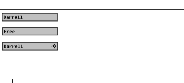
250 Using the iKVM Module
To choose the default display order of servers in the Main dialog box:
1
Select
Name
to display servers alphabetically by name.
or
Select
Slot
to display servers numerically by slot number.
2
Click
OK
.
To assign one or more key sequences for OSCAR activation:
1
Select a key sequence from the
Invoke OSCAR
menu.
2
Click
OK
.
The default key to invoke OSCAR is <Print Screen>.
To set a Screen Delay Time for the OSCAR:
1
Enter the number of seconds (0 through 9) to delay display of OSCAR
after you press <Print Screen>. Entering <0> launches OSCAR with no
delay.
2
Click
OK
.
Setting a time to delay display of OSCAR allows you to complete a soft
switch. To perform a soft switch, see "Soft Switching" on page 254.
Controlling the Status Flag
The status flag displays on your desktop and shows the name of the selected
server or the status of the selected slot. Use the Flag dialog box to configure
the flag to display by server, or to change the flag color, opacity, display time,
and location on the desktop.
Table 9-3. OSCAR Status Flags
Flag Description
Flag type by name
Flag indicating that the user has been disconnected
from all systems
Flag indicating that Broadcast mode is enabled

Using the iKVM Module 251
To access the Flag dialog box:
1
Press <Print Screen>. The
Main
dialog box appears.
2
Click
Setup
and then
Flag
. The
Flag
dialog box appears.
To specify how the status flag displays:
1
Select
Displayed
to show the flag all the time or
Displayed and Timed
to
display the flag for only five seconds after switching.
NOTE: If you select Timed by itself, the flag is not displayed.
2
Select a flag color from the
Display Color
section. Options are black, red,
blue, and purple.
3
In
Display Mode
, select
Opaque
for a solid color flag or
Transparent
to see
the desktop through the flag.
4
To position the status flag on the desktop:
a
Click
Set Position.
The
Set Position Flag
displays.
b
Left-click on the title bar and drag it to the desired location on the
desktop.
c
Right-click to return to the
Flag
dialog box.
NOTE: Changes made to the flag position are not saved until you click OK in the
Flag dialog box.
5
Click
OK
to save settings.
To exit without saving changes, click .
Managing Servers With iKVM
The iKVM is an analog switch matrix supporting up to 16 servers. The iKVM
switch uses the OSCAR user interface to select and configure your servers. In
addition, the iKVM includes a system input to establish a CMC command
line console connection to the CMC.
Peripherals Compatibility and Support
The iKVM is compatible with the following peripherals:
• Standard PC USB keyboards with QWERTY, QWERTZ, AZERTY, and
Japanese 109 layouts.
• VGA monitors with DDC support.

252 Using the iKVM Module
• Standard USB pointing devices.
• Self-powered USB 1.1 hubs connected to the local USB port on the iKVM.
• Powered USB 2.0 hubs connected to the Dell M1000e chassis’ front panel
console.
NOTE: You can use multiple keyboards and mice on the iKVM local USB port. The
iKVM aggregates the input signals. If there are simultaneous input signals from
multiple USB keyboards or mice, it may have unpredictable results.
NOTE: The USB connections are solely for supported keyboard, mouse, and USB
hubs. iKVM does not support data transmitted from other USB peripherals.
Viewing and Selecting Servers
Use the OSCAR Main dialog box to view, configure, and manage servers
through the iKVM. You can view your servers by name or by slot. The slot
number is the chassis slot number the server occupies. The Slot column
indicates the slot number in which a server is installed.
NOTE: The Dell CMC command line occupies Slot 17. Selecting this slot displays
the CMC command line, where you can execute remote RACADM commands or
connect to servers and modules for debugging.
NOTE: Server names and slot numbers are assigned by the CMC.
To access the Main dialog box:
Press <Print Screen> to launch the OSCAR interface. The Main dialog box
appears.
or
If a password has been assigned, the Password dialog box appears. Type your
password and click OK. The Main dialog box appears.
For more information about setting a password, see "Setting Console
Security" on page 255.
NOTE: There are four options for invoking OSCAR. You can enable one, multiple, or
all of these key sequences by selecting boxes in the Invoke OSCAR section of the
Main dialog box and then clicking OK.

Using the iKVM Module 253
Viewing the Status of Your Servers
The status of the servers in your chassis is indicated in the right columns of
the Main dialog box. The following table describe the status symbols.
Selecting Servers
Use the Main dialog box to select servers. When you select a server, the iKVM
reconfigures the keyboard and mouse to the proper settings for that server.
• To select servers:
Double-click the server name or the slot number.
or
If the display order of your server list is by slot (that is, the
Slot
button is
depressed), type the slot number and press <Enter>.
or
If the display order of your server list is by name (that is, the
Name
button
is depressed), type the first few characters of the server name, establish it
as unique, and press <Enter> twice.
• To select the previous server:
Press <Print Screen> and then <Backspace>. This key combination
toggles between the previous and current connections.
Table 9-4. OSCAR Interface Status Symbols
Symbols Description
(Green dot.) Server is online.
(Red X.) Server is offline or absent from chassis.
(Yellow dot.) Server is not available.
(Green A or B.) Server is being accessed by the user channel
indicated by the letter: A=rear panel, B=front panel.

254 Using the iKVM Module
• To disconnect the user from a server:
Press <Print Screen> to access OSCAR and then click
Disconnect
.
or
Press <Print Screen> and then <Alt><0>. This leaves you in a free
state, with no server selected. The status flag on your desktop, if active,
displays Free. See "Controlling the Status Flag" on page 250.
Soft Switching
Soft switching is switching between servers using a hotkey sequence. You can
soft switch to a server by pressing <Print Screen> and then typing the first
few characters of its name or number. If you previously set a delay time (the
number of seconds before the Main dialog box is displayed after <Print
Screen> is pressed) and you press the key sequences before that time has
elapsed, the OSCAR interface does not display.
To configure OSCAR for soft switching:
1
Press <Print Screen> to launch the OSCAR interface. The
Main
dialog
box appears.
2
Click
Setup
and then
Menu
. The
Menu
dialog box appears.
3
Select
Name
or
Slot
for the Display/Sort Key.
4
Type the desired delay time in seconds in the
Screen Delay Time
field.
5
Click
OK
.
To soft switch to a server:
• To select a server, press <Print Screen>.
If the display order of your server list is by slot as per your selection in
step 3 (that is, the
Slot
button is depressed), type the slot number and
press <Enter>.
or
If the display order of your server list is by name as per your selection in
step 3(that is, the
Name
button is depressed), type the first few characters
of the name of the server to establish it as unique and press <Enter>.
• To switch back to the previous server, press <Print Screen> then
<Backspace>.

Using the iKVM Module 255
Video Connections
The iKVM has video connections on the front and rear panels of the chassis.
The front panel connection signals take precedence over that of the rear
panel. When a monitor is connected to the front panel, the video connection
does not pass through to the rear panel, and an OSCAR message displays
stating that the rear panel KVM and ACI connections are disabled. If the
monitor is disabled (that is, removed from the front panel or disabled by a
CMC command), the ACI connection becomes active while the rear panel
KVM remains disabled. (For information about order of connection
precedence, see "iKVM Connection Precedences" on page 246.)
For information about enabling or disabling the front panel connection, see
"Enabling or Disabling the Front Panel" on page 263.
Preemption Warning
Normally, a user connected to a server console through the iKVM and another
user connected to the same server console through the iDRAC GUI console
redirection feature both have access to the console and are able to type
simultaneously.
To prevent this scenario, the remote user, before starting the iDRAC GUI
console redirection, can disable the local console in the iDRAC Web
interface. The local iKVM user sees an OSCAR message that the connection
will be preempted in a specified amount of time. The local user should finish
work before the iKVM connection to the server is terminated.
There is no preemption feature available to the iKVM user.
NOTE: If a remote iDRAC user has disabled the local video for a specific server,
that server's video, keyboard and mouse will be unavailable to the iKVM. The server
state is marked with a yellow dot in the OSCAR menu to indicate that it is locked or
unavailable for local use (see "Viewing the Status of Your Servers" on page 253).
Setting Console Security
OSCAR enables you to configure security settings on your iKVM console. You
can establish a screen saver mode that engages after your console remains
unused for a specified delay time. Once engaged, your console remains locked
until you press any key or move the mouse. Enter the screen saver password to
continue.

256 Using the iKVM Module
Use the Security dialog box to lock your console with password protection, set
or change your password, or enable the screen saver.
NOTE: If the iKVM password is lost or forgotten, you can reset it to the iKVM
factory default using the CMC Web interface or RACADM. See "Clearing a Lost or
Forgotten Password" on page 258.
Accessing the Security Dialog Box
1
Press <Print Screen>. The
Main
dialog box appears.
2
Click
Setup
and the
Security
. The
Security
dialog box appears.
Setting or Changing the Password
1
Single-click and press <Enter> or double-click in the
New
field.
2
Type the new password in the
New
field and then press <Enter>.
Passwords are case sensitive and require 5–12 characters. They must
include at least one letter and one number. Legal characters are: A–Z, a–z,
0–9, space, and hyphen.
3
In the
Repeat
field, type the password again, and then press <Enter>.
4
Click
OK
if you only want to change your password, and then close the
dialog box.
Password-protecting Your Console
1
Set your password as described in the previous procedure.
2
Select the
Enable Screen Saver
box.
3
Type the number of minutes of
Inactivity Time
(from 1 through 99) to
delay password protection and screen saver activation.
4
For
Mode
: If your monitor is ENERGY STAR
®
compliant, select
Energy
;
otherwise select
Screen
.
NOTE: If the mode is set to Energy, the appliance will put the monitor into
sleep mode. This is normally indicated by the monitor powering off and the
amber light replacing the green power LED. If the mode is set to Screen, the
OSCAR flag will bounce around the screen for the duration of the test. Before
the test starts, a warning popup box displays the following message: "Energy
mode may damage a monitor that is not ENERGY STAR compliant. However,
once started, the test can be quit immediately via mouse or keyboard
interaction."

Using the iKVM Module 257
CAUTION: Monitor damage may result from the use of Energy mode with monitors
not compliant with Energy Star.
5
Optional: To activate the screen saver test, click
Test
. The
Screen Saver
Test
dialog box displays. Click
OK
to start the test.
The test takes 10 seconds. When it concludes, you are returned to the
Security
dialog box.
Logging In
1
Press <Print Screen> to launch OSCAR. The
Password
dialog box
appears.
2
Type your password and then click
OK
.
The Main dialog box appears.
Setting Automatic Logout
You can set OSCAR to automatically log out of a server after a period of
inactivity.
1
In the
Main
dialog box, click
Setup
and then
Security
.
2
In the
Inactivity Time
field, enter the length of time you want to stay
connected to a server before it automatically disconnects you.
3
Click
OK
.
Removing Password Protection From Your Console
1
From the
Main
dialog box, click
Setup
and then
Security
.
2
In the
Security
dialog box, single-click and press <Enter>, or double-click
in the
New
field.
3
Leaving the
New
field empty, press <Enter>.
4
Single-click and press <Enter>, or double-click in the
Repeat
field.
5
Leaving the
Repeat
field empty, press <Enter>.
6
Click
OK
if you only want to eliminate your password.

258 Using the iKVM Module
Enabling Screen Saver Mode With No Password Protection
NOTE: If your console is password protected, you must first remove password
protection. Follow the steps in the previous procedure before following the steps
below.
1
Select
Enable Screen Saver
.
2
Type the number of minutes (1 through 99) that you want to delay
activation of the screen saver.
3
Select
Energy
if your monitor is ENERGY STAR compliant; otherwise
select
Screen
.
CAUTION: Monitor damage may result from the use of Energy mode with monitors
not compliant with Energy Star.
4
Optional: To activate the screen saver test, click
Test
. The
Screen Saver
Test
dialog box displays. Click
OK
to start the test.
The test takes 10 seconds. When it concludes, you are returned to the
Security
dialog box.
NOTE: Enabling screen saver mode disconnects the user from a server; no
server is selected. The status flag displays Free.
Exiting Screen Saver Mode
To exit screen saver mode and return to the Main dialog box, press any key or
move your mouse.
To turn off the screen saver:
1
In the
Security
dialog box, clear the
Enable Screen Saver
box.
2
Click
OK
.
To immediately turn on the screen saver, press <Print Screen>, then press
<Pause>.
Clearing a Lost or Forgotten Password
When the iKVM password is lost or forgotten, you can reset it to the iKVM
factory default, and then change the password. You can reset the password
using either the CMC Web interface or RACADM.

Using the iKVM Module 259
To reset a lost or forgotten iKVM password using the CMC Web interface:
1
Log in to the CMC Web interface.
2
Select
iKVM
from the Chassis submenu.
3
Click the
Setup
tab. The
iKVM Configuration
page displays.
4
Click
Restore Default Values
.
You can then change the password from the default using OSCAR. See
"Setting or Changing the Password" on page 256.
To reset a lost or forgotten password using RACADM, open a Telnet/SSH text
console to the CMC, log in, and type:
racadm racresetcfg -m kvm
NOTE: Using the racresetcfg command resets the Front Panel Enable and Dell
CMC Console Enable settings, if they are different from the default values.
For more information about the racresetcfg subcommand, see "racresetcfg"
on page 367.
Changing the Language
Use the Language dialog box to change the OSCAR text to display in any of
the supported languages. The text immediately changes to the selected
language on all of the OSCAR screens.
To change the OSCAR language:
1
Press <Print Screen>. The
Main
dialog box appears.
2
Click
Setup
and then
Language
. The
Language
dialog box appears.
3
Click the radio button for the desired language, and then click
OK
.
Displaying Version Information
Use the Version dialog box to display the iKVM firmware and hardware
versions, and to identify the language and keyboard configuration.

260 Using the iKVM Module
To display version information:
1
Press <Print Screen>. The
Main
dialog box appears.
2
Click
Command
s and then
Display Versions
. The
Version
dialog box
appears.
The top half of the
Version
dialog box lists the subsystem versions in the
appliance.
3
Click or press <Esc> to close the
Version
dialog box.
Scanning Your System
In scan mode, the iKVM automatically scans from slot to slot (server to
server). You can scan up to 16 servers by specifying which servers you want to
scan and the number of seconds that each server is displayed.
To add servers to the scan list:
1
Press <Print Screen>. The
Main
dialog box appears.
2
Click
Setup
and then
Scan
. The
Scan
dialog box appears,
listing of all
servers in the chassis
.
3
Select the box next to the servers you wish to scan.
or
Double-click the server name or slot.
or
Press <Alt > and the number of the server you wish to scan. You can select
up to 16 servers.
4
In the
Time
field, enter the number of seconds (3 through 99) that you
want iKVM to wait before the scan moves to the next server in the
sequence.
5
Click the
Add/Remove
button, and then click
OK
.
To remove a server from the Scan list:
1
In the
Scan
dialog box, select the box next to the server to be removed.
or
Double-click the server name or slot.

Using the iKVM Module 261
or
Click the
Clear
button to remove all servers from the
Scan
list.
2
Click the
Add/Remove
button, and then click
OK
.
To start Scan mode:
1
Press <Print Screen>. The
Main
dialog box appears.
2
Click
Commands
. The
Command
dialog box appears.
3
Select the
Scan Enable
box.
4
Click
OK
. A message appears indicating that the mouse and keyboard have
been reset.
5
Click to close the message box.
To cancel scan mode:
1
If OSCAR is open and the
Main
dialog box is displayed, select a server in
the list.
or
If OSCAR is
not
open, move the mouse or press any key on the keyboard.
Scanning stops at the currently selected server.
or
Press <Print Screen>. The
Main
dialog box appears; select a server in the
list.
2
Click the
Commands
button. The
Commands
dialog box appears.
3
Clear the
Scan Enable
box.
Broadcasting to Servers
You can simultaneously control more than one server in the system to ensure
that all selected servers receive identical input. You can choose to broadcast
keystrokes and/or mouse movements independently.
NOTE: You can broadcast up to 16 servers at a time.

262 Using the iKVM Module
To broadcast to servers:
1
Press <Print Screen>. The
Main
dialog box appears.
2
Click
Setup
and then
Broadcast
. The
Broadcast
dialog box appears.
NOTE: Broadcasting keystrokes: When using keystrokes, the keyboard state
must be identical for all servers receiving a broadcast for the keystrokes to be
interpreted identically. Specifically, the <Caps Lock> and <Num Lock> modes
must be the same on all keyboards. While the iKVM attempts to send
keystrokes to the selected servers simultaneously, some servers may inhibit
and thereby delay the transmission.
NOTE: Broadcasting mouse movements: For the mouse to work accurately,
all servers must have identical mouse drivers, desktops (such as identically
placed icons), and video resolutions. The mouse also must be in exactly the
same place on all screens. Because these conditions are extremely difficult to
achieve, broadcasting mouse movements to multiple servers may have
unpredictable results.
3
Enable mouse and/or keyboard for the servers that are to receive the
broadcast commands by selecting the boxes.
or
Press the up or down arrow keys to move the cursor to a target server. Then
press <Alt><K> to select the keyboard box and/or <Alt><M> to select
the mouse box. Repeat for additional servers.
4
Click
OK
to save the settings and return to the
Setup
dialog box. Click
or press <Escape> to return to the
Main
dialog box.
5
Click
Commands
. The
Commands
dialog box appears.
6
Click the
Broadcast Enable
box to activate broadcasting. The
Broadcast
Warning
dialog box appears.
7
Click O
K
to enable the broadcast.
To cancel and return to the
Commands
dialog box, click or press
<Esc>.
8
If broadcasting is enabled, type the information and/or perform the mouse
movements you want to broadcast from the management station. Only
servers in the list are accessible.
To turn broadcasting off:
From the Commands dialog box, clear the Broadcast Enable box.

Using the iKVM Module 263
Managing iKVM From the CMC
Enabling or Disabling the Front Panel
To enable or disable access to the iKVM from the front panel using
RACADM, open a Telnet/SSH text console to the CMC, log in, and type:
racadm config -g cfgKVMInfo -o cfgKVMFrontPanelEnable
<
value
>
where <value> is 1 (enable) or 0 (disable).
For more information about the config subcommand, see "config" on
page 322.
To enable or disable access to the iKVM from the front panel using the Web
interface:
1
Log in to the CMC Web interface.
2
Select iKVM in the system tree. The
iKVM Status
page displays.
3
Click the
Setup
tab. The
iKVM Configuration
page displays.
4
To enable, select the
Front Panel USB/Video Enabled
check box.
To disable, clear the
Front Panel USB/Video Enabled
check box.
5
Click
Apply
to save the setting.
Enabling the Dell CMC Console via iKVM
To enable the iKVM to access the Dell CMC console using RACADM, open a
Telnet/SSH text console to the CMC, log in, and type:
racadm config -g cfgKVMInfo -o
cfgKVMAccessToCMCEnable 1
To enable the Dell CMC console using the Web interface:
1
Log in to the CMC Web interface.
2
Select iKVM in the system tree. The
iKVM Status
page displays.
3
Click the
Setup
tab. The
iKVM Configuration
page displays.
4
Select the
Allow access to CMC CLI from iKVM
check box.
5
Click
Apply
to save the setting.

264 Using the iKVM Module
Viewing the iKVM Status and Properties
The local access KVM module for your Dell M1000e server chassis is called
the Avocent® Integrated KVM Switch Module, or iKVM. The health status of
the iKVM associated with the chassis can be viewed on the Chassis Properties
Health page under the Chassis Graphics section.
To view health status for the iKVM using Chassis Graphics:
1
Log in to the CMC Web interface.
2
The
Chassis Status
page is displayed. The right section of
Chassis
Graphics
depicts the rear view of the chassis and contains the health status
of the iKVM. iKVM health status is indicated by the color of the iKVM
subgraphic:
• Green - iKVM is present, powered on and communicating with the
CMC; there is no indication of an adverse condition.
• Amber - iKVM is present, but may or may not be powered on, or may
or may not be communicating with the CMC; an adverse condition
may exist.
• Gray - iKVM is present and not powered on. It is not communicating
with the CMC and there is no indication of an adverse condition.
3
Use the cursor to hover over the iKVM subgraphic and a corresponding
text hint or screen tip is displayed. The text hint provides additional
information on that iKVM.
4
The iKVM subgraphic is hyperlinked to the corresponding CMC GUI page
to provide immediate navigation to the
iKVM Status
page.
For more information about iKVM, see "Using the iKVM Module" on
page 245.
To view the status of the iKVM using the iKVM Status page:
1
Log in to the CMC Web interface.
2
Select
iKVM
in the system tree. The
iKVM Status
page displays.
Table 9-5 provides descriptions of the information provided on the iKVM
Status page.

Using the iKVM Module 265
Updating the iKVM Firmware
You can update the iKVM firmware using the CMC Web interface or
RACADM.
Table 9-5. iKVM Status Information
Item Description
Presence Indicates whether the iKVM module is Present or Absent.
Power State Indicates the power status of the iKVM: On, Off, or N/A
(Absent).
Name Displays the product name of the iKVM.
Manufacturer Displays in the manufacturer of the iKVM.
Part Number Displays the part number for the iKVM. The part number is a
unique identifier provided by the vendor.
Firmware Version Indicates the firmware version of the iKVM.
Hardware Version Indicates the hardware version of the iKVM.
Front Panel
Connected
Indicates whether the monitor is connected to the front panel
VGA connector (Yes or No). This information is provided to
the CMC so it can determine whether a local user has front-
panel access to the chassis.
Rear Panel
Connected
Indicates whether the monitor is connected to the rear panel
VGA connector (Yes or No). This information is provided to
the CMC so it can determine whether a local user has rear-
panel access to the chassis.
Tiering Port
Connected
The iKVM supports seamless tiering with external KVM
appliances from Dell and Avocent using built-in hardware.
When the iKVM is tiered, the servers in the chassis can be
accessed through the screen display of the external KVM
switch from which the iKVM is tiered.
Front Panel
USB/Video Enabled
Displays whether the front panel VGA connector is enabled
(Yes or No).
Allow access to CMC
from iKVM
Indicates whether the CMC command console through iKVM
is enabled (Yes or No).

266 Using the iKVM Module
To update the iKVM firmware using the CMC Web interface:
1
Log in to the CMC Web interface.
2
Click
Chassis
in the system tree.
3
Click the
Update
tab. The
Updatable Components
page displays.
4
Click the iKVM name. The
Firmware Update
page appears.
5
In the
Firmware Image
field, enter the path to the firmware image file on
your management station or shared network, or click
Browse
to navigate to
the file location.
NOTE: The default iKVM firmware image name is ikvm.bin; however, the iKVM
firmware image name can be changed by the user.
6
Click
Begin Firmware Update
. A dialog box prompts you to confirm the
action.
7
Click
Yes
to continue. The
Firmware Update Progress
section provides
firmware update status information. A status indicator displays on the
page while the image file uploads. File transfer time can vary greatly based
on connection speed. When the internal update process begins, the page
automatically refreshes and the Firmware update timer displays.
Additional items to note:
• Do not use the
Refresh
button or navigate to another page during the
file transfer.
• To cancel the process, click
Cancel File Transfer and Update
- this
option is available only during file transfer.
• Update status displays in the
Update State
field; this field is
automatically updated during the file transfer process. Certain older
browsers do not support these automatic updates. To manually refresh
the
Update State
field, click
Refresh
.
NOTE: The update may take up to one minute for the iKVM.
When the update is complete, iKVM resets and the new firmware is updated
and displayed on the Updatable Components page.
To update the iKVM firmware using RACADM, open a Telnet/SSH text
console to the CMC, log in, and type:
racadm fwupdate -g -u -a <
TFTP server IP address
> -d
<
filepath/filename
> -m kvm

Using the iKVM Module 267
For example:
racadm fwupdate -gua 192.168.0.10 -d ikvm.bin -m kvm
For more information about the fwupdate subcommand, see "fwupdate" on
page 329.
Troubleshooting
NOTE: If you have an active console redirection session and a lower resolution
monitor is connected to the iKVM, the server console resolution may reset if the
server is selected on the local console. If the server is running a Linux operating
system, an X11 console may not be viewable on the local monitor. Pressing
<Ctrl><Alt><F1> at the iKVM will switch Linux to a text console.
Table 9-6. Troubleshooting iKVM
Problem Likely Cause and Solution
The message "User has been disabled by
CMC control" appears on the monitor
connected to the front panel.
The front panel connection has been
disabled by the CMC.
You can enable the front panel using
either the CMC Web interface or
RACADM.
To enable the front panel using the Web
interface:
1
Log in to the CMC Web interface.
2
Select iKVM in the system tree.
3
Click the
Setup
tab.
4
Select the
Front Panel USB/Video
Enabled
check box.
5
Click
Apply
to save the setting.
To enable the front panel using
RACADM, open a Telnet/SSH text
console to the CMC, log in, and type:
racadm config -g cfgKVMInfo -
o cfgKVMAccesToCMCEnable 1

268 Using the iKVM Module
The rear panel access does not work. The front panel setting is enabled by the
CMC, and a monitor is currently
connected to the front panel.
Only one connection is allowed at a time.
The front panel connection has
precedence over ACI and the rear panel.
For more information about connection
precedence, see "iKVM Connection
Precedences" on page 246.
The message "User has been disabled as
another appliance is currently tiered"
appears on the monitor connected to the
rear panel.
A network cable is connected to the iKVM
ACI port connector and to a secondary
KVM appliance.
Only one connection is allowed at a time.
The ACI tiering connection has
precedence over the rear panel monitor
connection. The precedence order is front
panel, ACI, and then rear panel.
Table 9-6. Troubleshooting iKVM (continued)
Problem Likely Cause and Solution

Using the iKVM Module 269
The iKVM’s amber LED is blinking. There are three possible causes:
There is problem with the iKVM, for
which the iKVM requires reprogramming.
To fix the problem, follow the
instructions for updating iKVM firmware
(see "Updating the iKVM Firmware" on
page 265).
The iKVM is reprogramming the CMC
Console Interface. In this case, the CMC
Console is temporarily unavailable and
represented by a yellow dot in the OSCAR
interface. This process takes up to
15 minutes.
The iKVM firmware has detected a
hardware error. For additional
information, view the iKVM status.
To view iKVM status using the Web
interface:
1
Log in to the CMC Web interface.
2
Select iKVM in the system tree.
To view iKVM status using RACADM,
open a Telnet/SSH text console to the
CMC, log in, and type:
racadm getkvminfo
Table 9-6. Troubleshooting iKVM (continued)
Problem Likely Cause and Solution

270 Using the iKVM Module
My iKVM is tiered through the ACI port
to an external KVM switch, but all of the
entries for the ACI connections are
unavailable.
All of the states are showing a yellow dot
in the OSCAR interface.
The front panel connection is enabled
and has a monitor connected. Because the
front panel has precedence over all other
iKVM connections, the ACI and rear
panel connectors are disabled.
To enable your ACI port connection, you
must first disable front panel access or
remove the monitor connected to the
front panel. The external KVM switch
OSCAR entries will become active and
accessible.
To disable the front panel using the Web
interface:
1
Log in to the CMC Web interface.
2
Select iKVM in the system tree.
3
Click the
Setup
tab.
4
Clear (un-check) the
Front Panel
USB/Video Enabled
check box.
5
Click
Apply
to save the setting.
To disable the front panel using
RACADM, open a Telnet/SSH text
console to the CMC, log in, and type:
racadm config -g cfgKVMInfo -
o cfgKVMFrontPanelEnable 0
Table 9-6. Troubleshooting iKVM (continued)
Problem Likely Cause and Solution

Using the iKVM Module 271
In the OSCAR menu, the Dell CMC
connection is displaying a red X, and I
cannot connect to the CMC.
There are two possible causes:
The Dell CMC console has been
disabled. In this case, you can enable it
using either the CMC Web interface or
RACADM.
To enable the Dell CMC console using
the Web interface:
1
Log in to the CMC Web interface.
2
Select
iKVM
in the system tree.
3
Click the
Setup
tab.
4
Select the
Allow access to CMC CLI
from iKVM
check box.
5
Click
Apply
to save the setting.
To enable the Dell CMC connection
using RACADM, open a Telnet/SSH text
console to the CMC, log in, and type:
racadm config -g cfgKVMInfo -
o cfgKVMAccessToCMCEnable 1
The CMC is unavailable because it is
initializing, switching over to the standby
CMC, or reprogramming. In this case,
simply wait until the CMC finishes
initializing.
The slot name for a server is displayed as
"Initializing" in OSCAR, and I cannot
select it.
Either the server is initializing or the
iDRAC on that server failed initialization.
First, wait 60 seconds. If the server is still
initializing, the slot name will appear as
soon as initialization is complete, and you
can select the server.
If, after 60 seconds, OSCAR still indicates
that the slot is initializing, remove and
then re-insert the server in the chassis.
This action will allow iDRAC to re-
initialize.
Table 9-6. Troubleshooting iKVM (continued)
Problem Likely Cause and Solution

272 Using the iKVM Module

I/O Fabric Management 273
I/O Fabric Management
The chassis can hold up to six I/O modules (IOMs), each of which can be
pass-through or switch modules.
The IOMs are classified into three groups: A, B, and C. Each group has two
slots: Slot 1 and Slot 2. The slots are designated with letters, from left to right,
across the back of the chassis: A1 | B1 | C1 | C2 | B2 | A2. Each server has
slots for two mezzanine cards (MCs) to connect to the IOMs. The MC and
the corresponding IOM must have the same fabric.
The chassis supports three fabric or protocol types. The IOMs in a group
must have the same or compatible fabric types.
•
Group A
is always connected to the servers' on-board Ethernet adapters;
the fabric type of Group A will always be Ethernet.
•For
Group B,
the IOM slots are permanently connected to the
first MC
(
mezzanine card)
slot in each server module.
•For
Group C
, the IOM slots are permanently connected to the
second MC
(mezzanine card)
in each server module.
In addition, each MC can support two external links. For example, in the first
MC, the first link is permanently connected to slot 1 of Group B, and the
second link is permanently connected to slot 2 of Group B.
NOTE: In the CMC CLI, IOMs are referred to by the convention switch-n: A1=
switch-1, A2=switch-2, B1=switch-3, B2=switch-4, C1=switch-5, and C2=switch-6.
Fabric Management
Fabric management helps you avoid and take care of any electrical-,
configuration-, or connectivity-related problems due to installation of an
IOM that has a different fabric from the server or its MCs. Invalid hardware
configurations could cause electric or functional problems to the chassis or its
components. However, not all valid configurations are necessarily supported
configurations. Fabric management will only prevent invalid configurations
from powering on.
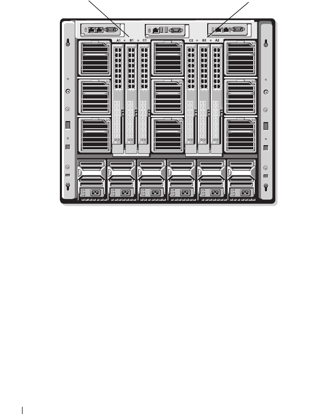
274 I/O Fabric Management
Figure 10-1 shows the location of IOMs in the chassis. The location of each
IOM in the chassis is indicated by its group number (A, B, or C) and slot
number (1 or 2). On the chassis, the IOM slot names are marked A1, A2, B1,
B2, C1, or C2.
Figure 10-1. Rear View of a Chassis, Showing the Location of the IOMs
The CMC creates entries in both the hardware log and CMC logs for invalid
hardware configurations.
For example:
• An Ethernet MC (mezzanine card) connected to a Fibre Channel IOM is
an invalid configuration. However, an Ethernet MC connected to both an
Ethernet switch and an Ethernet pass-through IOM installed in the same
IOM group is a valid connection.
• A Fibre Channel pass-through IOM and a fibre channel switch IOM in
slots B1 and B2 is a valid configuration if the first MCs on all of the servers
are also fibre channel. In this case, the CMC will power-on the IOMs and
the servers. However, certain fibre channel redundancy software may not
support this configuration.
Slots C2, B2, A2Slots A1, B1, C1

I/O Fabric Management 275
NOTE: Fabric verification for server MCs (mezzanine cards) is performed only
when the chassis is powered on. When the chassis is on standby power, the
iDRACs on the server modules remain powered off and thus are unable to report the
server's MC fabric type. The MC fabric type may not be reported in the CMC user
interface until the iDRAC on the server is powered on.
Invalid Configurations
There are three types of invalid configurations:
• Invalid MC (mezzanine card) configuration, where a newly installed MC
fabric is different from the existing IOM fabric
• Invalid IOM-MC configuration, where the newly installed IOM and MC
fabric does not match or is incompatible
• Invalid IOM-IOM configuration, where a newly installed IOM has a
different or incompatible fabric type from an IOM already installed in its
group
Invalid Mezzanine Card (MC) Configuration
An invalid MC configuration occurs when a single server’s MC is not
supported by its corresponding IOM. In this case, all the other servers in the
chassis can be running.
Invalid IOM-Mezzanine Card (MC) Configuration
The mismatched IOM will be held in the power-off state. The CMC adds an
entry to the CMC and hardware logs noting the invalid configuration and
specifying the IOM name. The CMC will also cause the error LED on the
offending IOM to blink. If the CMC is configured to send alerts, it sends
e-mail and/or SNMP alerts for this event.
For information about the CMC and hardware logs, see "Viewing the Event
Logs" on page 300.
Invalid IOM-IOM Configuration
The CMC holds a newly installed IOM in powered-off state, causes the
IOM’s error LED to blink, and creates entries in the CMC and hardware logs
about the mismatch.

276 I/O Fabric Management
For information about the CMC and hardware logs, see "Viewing the Event
Logs" on page 300.
Fresh Power-up Scenario
When the chassis is plugged in and powered up, the I/O modules have
priority over the servers. The first IOM in each group is allowed to power up
before the others. At this time, no verification of their fabric types is
performed. If there is no IOM on the first slot of a group, the module on the
second slot of that group powers up. If both slots have IOMs, the module in
the second slot is compared for consistency against the one in the first.
After the IOMs power up, the servers power up, and the CMC verifies the
servers for fabric consistency
A pass-through module and switch are allowed in the same group as long as
their fabric is identical. Switches and pass-through modules can exist in the
same group even if they were manufactured by different vendors.
Monitoring IOM Health
The health status for the IOMs can be viewed in two ways: from the Chassis
Graphics section on the Chassis Status page or the I/O Modules Status page.
The Chassis Graphics page provides a graphical overview of the IOMs
installed in the chassis.
To view health status of the IOMs using Chassis Graphics:
1
Log in to the CMC Web interface.
2
The
Chassis Status
page is displayed. The right section of
Chassis
Graphics
depicts the rear view of the chassis and contains the health status
for the IOMs. IOM health status is indicated by the color of the IOM
subgraphic:
• Green - IOM is present, powered on and communicating with the
CMC; there is no indication of an adverse condition.
• Amber - IOM is present, but may or may not be powered on, or may or
may not be communicating with the CMC; an adverse condition may
exist.
• Gray - IOM is present and not powered on. It is not communicating
with the CMC and there is no indication of an adverse condition.

I/O Fabric Management 277
3
Use the cursor to hover over an individual IOM subgraphic and a
corresponding text hint or screen tip is displayed. The text hint provides
additional information on that IOM.
4
The IOM subgraphic is hyperlinked to the corresponding CMC GUI page
to provide immediate navigation to the
I/O Module Status
page
associated with that IOM.
To view the health status of all IOMs using the I/O Modules Status page:
1
Log in to the CMC Web interface.
2
Select
I/O Modules
in the
Chassis
menu in the system tree.
3
Click the
Properties
tab.
4
Click the
Status
sub-tab. The
I/O Modules Status
page displays.

278 I/O Fabric Management
Table 10-1 provides descriptions of the information provided on the I/O
Modules Status page.
Table 10-1. I/O Modules Health Status Information
Item Description
Present Indicates whether the IOM is Present or Absent.
Health OK Indicates that the IOM is present and
communicating with the CMC. In the event of a
communication failure between the CMC and
the server, the CMC cannot obtain or display
health status for the IOM.
Informational Displays information about the IOM when no
change in health status (OK, Warning, Severe)
has occurred.
Warning Indicates that only warning alerts have been
issued, and corrective action must be taken
within the time frame set by the administrator.
If corrective actions are not taken within the
administrator-specified time, it could lead to
critical or severe failures that can affect the
integrity of the IOM.
Examples of conditions causing Warnings: IOM
fabric mismatch with the server's mezzanine
card fabric; invalid IOM configuration, where
the newly installed IOMs do not match the
existing IOM on the same group.
Severe Indicates at least one Failure alert has been
issued. Severe status represents a system failure
on the IOM, and corrective action must be
taken immediately.
Examples of conditions causing Severe status:
Failure in IOM detected; IOM was removed.
NOTE: Any change in health is logged to both the hardware and CMC
log. For more information, see "Viewing the Event Logs" on page 300.
Slot Indicates the location of the IOM in the chassis by group number (A,
B, or C) and slot number (1 or 2). Slot names: A1, A2, B1, B2, C1,C2.

I/O Fabric Management 279
Viewing the Health Status of an Individual IOM
The I/O Module Status page (separate from the I/O Modules Status page)
provides an overview of an individual IOM.
To view the health status of an individual IOM:
1
Log in to the CMC Web interface.
2
Expand
I/O Modules
in the system tree. All of the IOMs (1–6) appear in
the expanded
I/O Modules
list.
3
Click the IOM you want to view in the
I/O Modules
list in the system tree.
4
Click the
Status
sub-tab. The
I/O Modules Status
page displays.
Fabric Indicates the type of fabric for the IOM: Gigabit Ethernet, 10GE
XAUI, 10GE KR, 10GE XAUI KR, FC 4 Gbps, FC 8 Gbps, SAS 3
Gbps, SAS 6 Gbps, Infiniband SDR, Infiniband DDR, Infiniband
QDR, PCIe Bypass Generation 1, PCIe Bypass Generation 2.
NOTE: Knowing the fabric types of the IOMs in your chassis is critical in
preventing IOM mismatches within the same group. For information
about I/O fabric, see "I/O Fabric Management" on page 273.
Name Displays the IOM product name.
Power Status Indicates the power status of the IOM: On, Off, or N/A (Absent).
Service Tag Displays the service tag for the IOM. The service tag a unique
identifier provided by Dell for support and maintenance.
Any change in health is logged to both the hardware and CMC log.
For more information, see "Viewing the Event Logs" on page 300.
NOTE: Passthroughs do not have service tags. Only switches have
service tags.
Table 10-1. I/O Modules Health Status Information (continued)
Item Description

280 I/O Fabric Management
Table 10-2 provides descriptions of the information provided on the I/O
Module Status page.
Table 10-2. I/O Module Health Status Information
Item Description
Name Displays name of the IOM.
Present Indicates whether the IOM is Present or Absent.
Health OK Indicates that the IOM is present and
communicating with the CMC. In the event of
a communication failure between the CMC
and the server, the CMC cannot obtain or
display health status for the IOM.
Informational Displays information about the IOM when no
change in health status (OK, Warning, Severe)
has occurred.
Examples of conditions causing Informational
status: the IOM presence was detected; a user
requested IOM power cycle.

I/O Fabric Management 281
Warning Indicates that only warning alerts have been
issued, and corrective action must be taken
within the time frame set by the
administrator. If corrective actions are not
taken within the administrator-specified time,
it could lead to critical or severe failures that
can affect the integrity of the IOM.
Examples of conditions causing Warnings:
IOM fabric mismatch with the server's
mezzanine card fabric; invalid IOM
configuration, where the newly installed IOMs
do not match the existing IOM on the same
group.
Severe Indicates at least one Failure alert has been
issued. Severe status represents a system
failure on the IOM, and corrective action must
be taken immediately.
Examples of conditions causing Severe status:
Failure in IOM detected; IOM was removed.
NOTE: Any change in health is logged to both the hardware and CMC
log. For information on viewing logs, see "Viewing the Hardware Log"
on page 300 and "Viewing the CMC Log" on page 303.
Location Indicates the location of the IOM in the chassis by group number
(A, B, or C) and slot number (1 or 2). Slot names: A1, A2, B1, B2,
C1, or C2.
Power Status Indicates the power status of the IOM: On, Off, or N/A (Absent).
Service Tag Displays the service tag for the IOM. The service tag a unique
identifier provided by Dell for support and maintenance.
Fabric Indicates the type of fabric for the IOM: Gigabit Ethernet, 10GE
XAUI, 10GE KR, 10GE XAUI KR, FC 4 Gbps, FC 8 Gbps, SAS 3
Gbps, SAS 6 Gbps, Infiniband SDR, Infiniband DDR, Infiniband
QDR, PCIe Bypass Generation 1, PCIe Bypass Generation 2.
NOTE: Knowing the fabric types of the IOMs in your chassis is critical
in preventing IOM mismatches within the same group. For information
about I/O fabric, see "I/O Fabric Management" on page 273.
Table 10-2. I/O Module Health Status Information (continued)
Item Description

282 I/O Fabric Management
Configuring Network Settings for an Individual IOM
The I/O Modules Configuration page allows you to configure the server
network settings for configuring and managing the IOM within the chassis.
For Ethernet switches, the out-of-band management port (IP address) is what
is configured. The in-band management port (that is, VLAN1) is not
configured using this interface.
NOTE: To change settings on the I/O Modules Configuration page, you must have
Fabric A Administrator privileges to configure IOMs Group A; Fabric B
Administrator privileges to configure IOMs Group B; or Fabric C Administrator
privileges to configure IOMs Group C.
NOTE: For Ethernet switches, the in-band (VLAN1) and out-of-band management
IP addresses cannot be the same or on the same network; this will result in the out-
of-band IP address not being set. Refer to the IOM documentation for the default
in-band management IP address.
NOTE: Only those IOMs present in the chassis are displayed.
NOTE: Do not configure I/O module network settings for Ethernet passthrough and
Infiniband switches.
To configure the network settings for an individual IOM:
1
Log in to the CMC Web interface.
2
Click
I/O Modules
in the system tree. Click the
Setup
sub-tab. The
Configure I/O Modules Network Settings
page displays.
MAC Address Displays the MAC address for the IOM. The MAC address is a
unique address assigned to a device by the hardware vendor as a
means for identification.
NOTE: Passthroughs do not have MAC addresses. Only switches
have MAC addresses.
Role Displays the I/O module stacking membership when modules are
linked together:
•
Member
- the module is part of a stack set
•
Master
- the module is a primary access point.
Table 10-2. I/O Module Health Status Information (continued)
Item Description

I/O Fabric Management 283
3
To configure network settings for I/O modules, type/select values for the
following properties, and then click
Apply
.
NOTE: Only IOMs that are powered on can be configured.
NOTE: The IP address set on the IOMs from the CMC is not saved to the switch's
permanent startup configuration. To save the IP address configuration permanently,
you must enter the connect switch-n RACADM command or use a direct
interface to the IOM GUI to save this address to the startup configuration file.
Table 10-3. Configure I/O Module Network Settings
Item Description
Slot Indicates the location of the IOM in the chassis by group number
(A, B, or C) and slot number (1 or 2). Slot names: A1, A2, B1, B2,
C1, or C2. (The Slot value cannot be changed.)
Name Displays the IOM product name. (The IOM name cannot be
changed.)
Power State Displays the Power State of the IOM. (The Power State cannot be
changed from this page.)
DHCP Enabled Enables the IOM on the chassis to request and obtain an IP address
from the Dynamic Host Configuration Protocol (DHCP) server
automatically.
Default: Checked (enabled).
If this option is checked, the IOM retrieves IP configuration (IP
address, subnet mask, and gateway) automatically from a DHCP
server on your network.
NOTE: When this feature is enabled, the IP Address, Gateway, and
Subnet Mask property fields (located immediately adjacent following
this option) are inactivated, and any previously entered values for
these properties are ignored.
If this option is not checked, you must manually enter a valid IP
address, gateway, and subnet mask in the corresponding text fields
immediately following this option.
IP Address Specifies the IP address for the IOM network interface.
Subnet Mask Specifies the subnet mask for the IOM network interface.
Gateway Specifies the gateway for the IOM network interface.

284 I/O Fabric Management
Troubleshooting IOM Network Settings
The following list contains troubleshooting items for IOM network settings:
• The CMC can read the IP address setting too quickly after a configuration
change; it will display
0.0.0.0
after clicking
Apply.
You must hit the refresh
button in order to see if the IP address is set correctly on the switch.
• If an error is made in setting the IP/mask/gateway, the switch will not set
the IP address and will return a
0.0.0.0
in all fields. Common errors are:
• Setting the out-of-band IP address to be the same as, or on the same
network as, the in-band management IP address.
• Entering an invalid subnet mask.
• Setting the default gateway to an address that is not on a network that
is directly connected to the switch.
For more information on IOM network settings, refer to the Dell™
PowerConnect™ M6220 Switch Important Information document and the
Dell™ PowerConnect™ 6220 Series Port Aggregator White Paper.

Troubleshooting and Recovery 285
Troubleshooting and Recovery
Overview
This section explains how to perform tasks related to recovering and
troubleshooting problems on the remote system using the CMC Web
interface.
• Managing power on a remote system
• Viewing chassis information
• Viewing the event logs
• Using the Diagnostic Console
• Troubleshooting network problems
• Troubleshooting alerting problems
• Disabling forgotten password
• Error codes and logs
Chassis Monitoring Tools
Configuring LEDs to Identify Components on the Chassis
You can set component LEDs for all or individual components (chassis,
servers, and IOMs) to blink as a means of identifying the component on the
chassis.
NOTE: To modify these settings, you must have Chassis Configuration
Administrator privilege.
Using the Web Interface
To enable blinking for one, multiple, or all component LEDs:
1
Log in to the CMC Web interface.
2
Click
Chassis
in the system tree.
3
Click the
Troubleshooting
tab.

286 Troubleshooting and Recovery
4
Click the
Identify
sub-tab. The
Identify
page displays, featuring a list of
all components on the chassis.
5
To enable blinking for a component LED, check the box beside the device
name and then click
Blink
.
6
To disable blinking for a component LED, check the box beside the device
name and then click
UnBlink
.
Using RACADM
Open a Telnet/SSH text console to the CMC, log in, and type:
racadm setled -m <
module
> [-l <
ledState
>]
where
<
module
>
specifies the module whose LED you want to configure.
Configuration options:
•
server-
n
where
n
=1–16
•
switch-
n
where
n
=1–6
•cmc-active
and
<
ledState
>
specifies whether the LED should blink.
Configuration options:
• 0 — not blinking (default)
• 1 — blinking
Configuring SNMP Alerts
Simple network management protocol (SNMP) traps, or event traps, are
similar to email event alerts. They are used by a management station to
receive unsolicited data from the CMC.
You can configure the CMC to generate event traps. Table 11-1 provides an
overview of the events that trigger SNMP and email alerts. For information on
email alerts, see "Configuring Email Alerts" on page 291.
Table 11-1. Chassis Events That Can Generate SNMP and Email Alerts
Event Description
Fan Probe Failure A fan is running too slow or not at all.
Battery Probe Warning A battery has stopped functioning.

Troubleshooting and Recovery 287
You can add and configure SNMP alerts using the Web interface or
RACADM.
Using the Web Interface
NOTE: To add or configure SNMP alerts, you must have Chassis Configuration
Administrator privilege.
Temperature Probe
Warning
The temperature is approaching excessively high or low
limits.
Temperature Probe Failure The temperature is either too high or too low for proper
operation.
Redundancy Degraded Redundancy for the fans and/or power supplies has been
reduced.
Redundancy Lost No redundancy remains for the fans and/or power
supplies.
Power Supply Warning The power supply is approaching a failure condition.
Power Supply Failure The power supply has failed.
Power Supply Absent An expected power supply is not present.
Hardware Log Failure The hardware log is not functioning.
Hardware Log Warning The hardware log is almost full.
Server Absent An expected server is not present.
Server Failure The server is not functioning.
KVM Absent An expected KVM is not present.
KVM Failure The KVM is not functioning.
IOM Absent An expected IOM is not present.
IOM Failure The IOM is not functioning.
Firmware Mismatch There is a firmware mismatch for the chassis or server
firmware.
Table 11-1. Chassis Events That Can Generate SNMP and Email Alerts (continued)
Event Description

288 Troubleshooting and Recovery
NOTE: For added security, Dell strongly recommends that you change the default
password of the root (User 1) account. The root account is the default
administrative account that ships with the CMC. To change the default password for
the root account, click User ID 1 to open the User Configuration page. Help for that
page is available through the Help link at the top right corner of the page.
1
Log in to the CMC Web interface.
2
Select
Chassis
in the system tree.
3
Click the
Alert Management
tab. The
Chassis Events
page appears.
4
Enable alerting:
a
Select the check boxes of the events for which you want to enable
alerting. To enable all events for alerting, select the
Select All
check
box.
b
Click
Apply
to save your settings.
5
Click the
Traps Settings
sub-tab. The
Chassis Event Alert Destinations
page displays.
6
Type a valid IP address in an empty
Destination IP Address
field.
7
Ty p e th e
SNMP Community String
to which the destination
management station belongs.
NOTE: The community string on the Chassis Event Alert Destinations page
differs from the community string on the Chassis→ Network/Security→
Services page. The SNMP traps community string is the community that the
CMC uses for outbound traps destined to management stations. The
community string on the Chassis→ Network/Security→ Services page is the
community string that management stations use to query the SNMP daemon
on the CMC.
8
Click
Apply
to save your changes.
To test an event trap for an alert destination:
1
Log in to the CMC Web interface.
2
Select
Chassis
in the system tree.
3
Click the
Alert Management
tab. The
Chassis Events
page appears.
4
Click the
Traps Settings
tab. The
Chassis Event Alert Destinations
page
displays.
5
Click
Send
in the
Test Trap
column beside the destination.

Troubleshooting and Recovery 289
Using RACADM
1
Open a Telnet/SSH text console to the CMC and log in.
NOTE: Only one filter mask may be set both SNMP and email alerting. You
may skip step 2 if you have already selected filter mask.
2
Enable alerting by typing:
racadm config -g cfgAlerting -o cfgAlertingEnable
1
3
Specify the events for which you want the CMC to generate by typing:
racadm config -g cfgAlerting -o
cfgAlertingFilterMask <
mask value
>
where
<mask value>
is a hex value between 0x0 and 0x003fffdf.
To obtain the mask value, use a scientific calculator in hex mode and add
the second values of the individual masks (1, 2, 4, etc.) using the <OR>
key.
For example, to enable trap alerts for Battery Probe Warning (0x2), Power
Supply Failure (0x1000), and KVM failure (0x80000), key 2 <OR> 1000
<OR> 200000 and press the <=> key.
The resulting hex value is 208002, and the mask value for the RACADM
command is 0x208002.
Table 11-2. Event Traps Filter Masks
Event Filter Mask Value
Fan Probe Failure 0x1
Battery Probe Warning 0x2
Temperature Probe Warning 0x8
Temperature Probe Failure 0x10
Redundancy Degraded 0x40
Redundancy Lost 0x80
Power Supply Warning 0x800
Power Supply Failure 0x1000
Power Supply Absent 0x2000

290 Troubleshooting and Recovery
4
Enable traps alerting by typing:
racadm config -g cfgTraps -o cfgTrapsEnable 1 -i
<
index
>
where
<index>
is a value 1–4. The index number is used by the CMC to
distinguish up to four configurable IP destinations for traps alerts.
5
Specify a destination IP address to receive the traps alert by typing:
racadm config -g cfgTraps -o
cfgTrapsAlertDestIPAddr
<IP address>
-i <
index
>
where
<IP address>
is a valid IP address, and
<index>
is the index
value you specified in step 4.
6
Specify the community name by typing:
racadm config -g cfgTraps -o cfgTrapsCommunityName
<community name>
-i <
index
>
where
<community name>
is the SNMP community to which the
chassis belongs, and
<index>
is the index value you specified in steps 4
and 5.
You can configure up to four destination IP addresses to receive traps alerts.
To add more IP addresses, repeat steps 2–6.
Hardware Log Failure 0x4000
Hardware Log Warning 0x8000
Server Absent 0x10000
Server Failure 0x20000
KVM Absent 0x40000
KVM Failure 0x80000
IOM Absent 0x100000
IOM Failure 0x200000
Firmware mismatch 0x400000
Table 11-2. Event Traps Filter Masks (continued)
Event Filter Mask Value

Troubleshooting and Recovery 291
NOTE: The commands in steps 2–6 will overwrite any existing settings configured
for the index you specify (1–4). To determine whether an index has previously
configured values, type: racadm getconfig -g cfgTraps -i <index>. If the index is
configured, values will appear for the cfgTrapsAlertDestIPAddr and
cfgTrapsCommunityName objects.
To test an event trap for an alert destination:
racadm testtrap -i <
index
>
where
<index>
is a value 1–4 representing the alert destination you want to
test. If you are unsure of the index number, type:
racadm getconfig -g cfgTraps -i <
index
>
Configuring Email Alerts
When the CMC detects a chassis event, such as an environmental warning or
a component failure, it can be configured to send an email alert to one or
more email addresses.
Table 11-1 provides an overview of the events that trigger email and SNMP
alerts. For information on SNMP alerts, see "Configuring SNMP Alerts" on
page 286.
You can add and configure email alerts using the Web interface or RACADM.
Using the Web Interface
NOTE: To add or configure email alerts, you must have Chassis Configuration
Administrator privilege.
1
Log in to the CMC Web interface.
2
Select
Chassis
in the system tree.
3
Click the
Alert Management
tab. The
Chassis Events
page appears.
4
Enable alerting:
a
Select the check boxes of the events for which you want to enable
alerting. To enable all events for alerting, select the
Select All
check
box.
b
Click
Apply
to save your settings.
5
Click the
Email Alert Settings
sub-tab. The
Email Alert Destinations
page displays.

292 Troubleshooting and Recovery
6
Specify the SMTP server IP address:
a
Locate the
SMTP (Email) Server
field, and then type the SMTP
hostname or IP address.
NOTE: You must configure the SMTP email server to accept relayed emails
from the CMC's IP address, a feature which is normally turned off in most mail
servers due to security concerns. For instructions as to how to accomplish
this in a secure manner, refer to the documentation that came with your SMTP
server.
b
Enter the desired originator email for the alert, or leave it blank to use
the default email originator. The default is cmc@[IP_address] where
[IP_address] is the IP address of the CMC. If you choose to enter a
value, the syntax of the email name is emailname[@domain], and an
email domain can be optionally specified. If @domain is not specified
and there is an active CMC network domain, then the email address
of emailname@cmc.domain is used as the source email. If @domain
is not specified and CMC has no active network domain, then the IP
address of the CMC is used (for example, emailname@[IP_address]).
c
Click
Apply
to save your changes.
7
Specify the email address(es) that will receive the alerts:
a
Type a valid email address in an empty
Destination Email Address
field.
b
Enter an optional
Name
. This is the name of the entity receiving the
email. If a name is entered for an invalid email address, it is ignored.
c
Click
Apply
to save your settings.
To send a test email to an email alert destination:
1
Log in to the CMC Web interface.
2
Select
Chassis
in the system tree.
3
Click the
Alert Management
tab. The
Chassis Events
page appears.
4
Click the
Email Alert Settings
sub-tab. The
Email Alert Destinations
page displays.
5
Click
Send
in the
Destination Email Address
column beside the
destination.

Troubleshooting and Recovery 293
Using RACADM
1
Open a Telnet/SSH text console to the CMC and log in.
2
Enable alerting by typing:
racadm config -g cfgAlerting -o cfgAlertingEnable
1
NOTE: Only one filter mask may be set by both SNMP and email alerting. You
may skip step 3 if you have already set a filter mask.
3
Specify the events for which you want the CMC to generate by typing:
racadm config -g cfgAlerting -o
cfgAlertingFilterMask <
mask value
>
where
<mask value>
is a hex value between 0x0 and 0x003fffdf and
must be expressed with the leading
0x
characters. Table 11-2 provides filter
masks for each event type. For instructions on calculating the hex value for
the filter mask you want to enable, see step 3 on "Using RACADM" on
page 289.
4
Enable email alerting by typing:
racadm config -g cfgEmailAlert -o
cfgEmailAlertEnable 1 -i <
index
>
where
<index>
is a value 1–4. The index number is used by the CMC to
distinguish up to four configurable destination email addresses.
5
Specify a destination email address to receive the email alerts by typing:
racadm config -g cfgEmailAlert -o
cfgEmailAlertAddress
<email address>
-i <
index
>
where
<email address>
is a valid email address, and
<index>
is the
index value you specified in step 4.
6
Specify the name of the party receiving the email alert by typing:
racadm config -g cfgEmailAlert -o
cfgEmailAlertEmailName
<email name>
-i <
index
>
where
<email name>
is the name of the person or group receiving the
email alert, and
<index>
is the index value you specified in steps 4 and 5.
The email name can contain up to 32 alphanumeric characters, dashes,
underscores, and periods. Spaces are not valid.

294 Troubleshooting and Recovery
You can configure up to four destination email addresses to receive email
alerts. To add more email addresses, repeat steps 2–6.
NOTE: The commands in steps 2–6 will overwrite any existing settings configured
for the index you specify (1–4). To determine whether an index has previously
configured values, type: racadm getconfig -g cfgEmailAlert -i <index>. If the index is
configured, values will appear for the cfgEmailAlertAddress and
cfgEmailAlertEmailName objects.
First Steps to Troubleshooting a Remote System
The following questions are commonly used to troubleshoot high-level
problems in the managed system:
1
Is the system powered on or off?
2
If powered on, is the operating system functioning, crashed, or just frozen?
3
If powered off, did the power turn off unexpectedly?
Monitoring Power and Executing Power Control
Commands on the Chassis
You can use the Web interface or RACADM to:
• View the system’s current power status.
• Perform an orderly shutdown through the operating system when
rebooting, and power the system on or off.
For information about power management on the CMC and configuring
power budget, redundancy, and power control, see "Power Management" on
page 215.
Viewing Power Budget Status
For instructions on viewing power budget status for the chassis, servers, and
PSUs using either the Web interface or RACADM, see "Viewing Power
Budget Status" on page 224.

Troubleshooting and Recovery 295
Executing a Power Control Operation
For instructions on powering on, powering off, resetting, or power-cycling the
system using the CMC Web interface or RACADM, see "Executing Power
Control Operations on the Chassis" on page 241, "Executing Power Control
Operations on an IOM" on page 242, and "Executing Power Control
Operations on a Server" on page 243.
Viewing Chassis Summaries
The CMC provides rollup overviews of the chassis, primary and standby
CMCs, iKVM, fans, temperature sensors, and I/O modules (IOMs).
Using the Web Interface
To view summaries of the chassis, CMCs, iKVM, and IOMs:
1
Log in to the CMC Web interface.
2
Select
Chassis
in the system tree.
3
Click the
Summary
tab. The
Chassis Summary
page displays.
Table 11-3, Table 11-4, Table 11-5, and Table 11-6 describe the information
provided.
Table 11-3. Chassis Summary
Item Description
Name Displays the name of the chassis. The name identifies the
chassis on the network. For information on setting the name
of the chassis, see "Editing Slot Names" on page 99.
Model Displays the chassis model or manufacturer. For example,
PowerEdge 2900.
Service Tag Displays the service tag of the chassis. The service tag is a
unique identifier provided by the manufacturer for support
and maintenance.
Asset Tag Displays the asset tag of the chassis.
Location Displays the location of the chassis.
CMC Failover Ready Indicates (Yes, No) whether the standby CMC (if present) is
capable of taking over in the event of a failover condition.

296 Troubleshooting and Recovery
System Power Status Displays the system power status.
Table 11-4. CMC Summary
Item Description
Primary CMC Information
Name Displays the name of the CMC. For example, Primary CMC
or Standby CMC.
Description Provides a brief description of the purpose of the CMC.
Date/Time Indicates the date and time set on the active or primary
CMC.
Location Indicates the slot location of the active or primary CMC.
Primary Firmware
Version
Indicates the firmware version of the active or primary CMC.
Firmware Last
Updated
Indicates when the firmware was last updated. If no updates
have occurred, this property displays as N/A.
Hardware Version Indicates the hardware version of the active or primary CMC.
MAC Address Indicates the MAC address for the CMC NIC. The MAC
address is a unique identifier for the CMC over the network.
IP Address Indicates the IP address of the CMC NIC.
Gateway Indicates the gateway of the CMC NIC.
Subnet Mask Indicates the subnet mask of the CMC NIC.
Use DHCP (for NIC IP
Address)
Indicates whether the CMC is enabled to request and obtain
automatically an IP address from the Dynamic Host
Configuration Protocol (DHCP) server (Yes or No). The
default setting for this property is No.
Primary DNS Server Indicates the primary DNS server name.
Alternate DNS Server Indicates the alternate DNS server name.
Use DHCP for DNS
Domain Name
Indicates use of DHCP to acquire the DNS Domain name
(Yes, No).
Table 11-3. Chassis Summary (continued)
Item Description

Troubleshooting and Recovery 297
DNS Domain Name Indicates the DNS Domain name.
Standby CMC Information
Present Displays (Yes, No) whether a second (standby) CMC is
installed.
Standby Firmware
Version
Displays the CMC firmware version installed on the standby
CMC.
Table 11-5. iKVM Summary
Item Description
Present Indicates whether the iKVM module is present (Yes or No).
Name Displays the name of the iKVM. The name identifies the
iKVM on the network.
Manufacturer Displays the iKVM model or manufacturer.
Part Number Displays the part number for the iKVM. The part number is a
unique identifier provided by the vendor. Part number
naming conventions differ from vendor to vendor.
Firmware Version Indicates the firmware version of the iKVM.
Hardware Version Indicates the hardware version of the iKVM.
Power Status Indicates the power status of the iKVM: On, Off, N/A
(Absent).
Front Panel
USB/Video Enabled
Indicates whether the front panel VGA and USB connectors
are enabled (Yes or No).
Allow Access to CMC
CLI from iKVM
Indicates that CLI access is enabled on the iKVM (Yes or
No).
Table 11-4. CMC Summary (continued)
Item Description

298 Troubleshooting and Recovery
Using RACADM
1
Open a Telnet/SSH text console to the CMC and log in.
2
To view chassis and CMC summaries, type:
racadm getsysinfo
To view the iKVM summary, type:
racadm getkvminfo
To view the IOM summary, type:
racadm getioinfo
Viewing Chassis and Component Health Status
Using the Web Interface
To view chassis and component health summaries:
1
Log in to the CMC Web interface.
2
Select
Chassis
in the system tree. The
Chassis Status
page displays.
The Chassis Graphics section provides a graphical view of the front and
rear of the chassis. This graphical representation provides a visual
Table 11-6. IOM Summary
Item Description
Location Indicates the slot occupied by the IOMs. Six slots are
identified by group name (A, B, or C) and slot number
(1 or 2). Slot names: A-1, A-2, B-1, B-2, C-1, or C-2.
Present Indicates whether the IOM is present (Yes or No).
Name Displays the name of the IOM.
Fabric Displays the type of fabric.
Power Status Indicates the power status of the IOM: On, Off, or N/A
(Absent).
Service Tag Displays the service tag of the IOM. The service tag a unique
identifier provided by the manufacturer for support and
maintenance.

Troubleshooting and Recovery 299
overview of the components installed within the chassis and its
corresponding status.
Each graphic displays a real-time representation of the installed
components. The component state is indicated by the color of the
component subgraphic.
• Green - the component is present, powered on and communicating
with the CMC; there is no indication of an adverse condition.
• Amber - the component is present, but may or may not be powered
on, or may or may not be communicating with the CMC; an adverse
condition may exist.
• Gray - the component is present and not powered on. It is not
communicating with the CMC and there is no indication of an
adverse condition.
All components display a corresponding text hint or screen tip when the
mouse is placed over the component subgraphic. Component status is
dynamically updated, and the component subgraphic colors and text hints
are automatically changed to reflect the current state.
The component subgraphic is also hyperlinked to the corresponding CMC
GUI page to provide immediate navigation to the status page for that
component.
The
Component Health
section displays status for each component with
an icon. Table 11-7 provides descriptions of each icon.
Table 11-7. Health Status Indicators
Item Description
OK Indicates that the component is present and
communicating with the CMC.
Informational Displays information about the component when there
is no change in health status.

300 Troubleshooting and Recovery
Using RACADM
Open a Telnet/SSH text console to the CMC, log in, and type:
racadm getmodinfo
Viewing the Event Logs
The Hardware Log and CMC Log pages display system-critical events that
occur on the managed system.
Viewing the Hardware Log
The CMC generates a hardware log of events that occur on the chassis. You
can view the hardware log using the Web interface and remote RACADM.
NOTE: To clear the hardware log, you must have Clear Logs Administrator
privilege.
Warning Indicates that only Warning alerts have been issued, and
corrective action must be taken within the time frame
set by the administrator. If corrective actions are not
taken within administrator-specified time, it could lead
to a component failure, communication failure between
the component and the CMC, and a critical or severe
failure that could affect the integrity of the chassis.
Severe Indicates that at least one failure alert has been issued.
This means that the CMC can still communicate with
the component and that the health status reported is
critical. Corrective action must be taken immediately.
Failure to do so may cause the component to fail and
stop communicating with the CMC.
Unknown Displays when the chassis is first powered on. All chassis
components initially are indicated as "unknown" until
they are fully powered on.
No Value Indicates that the component is absent from the slot, or
the CMC cannot communicate with the component.
NOTE: It is not possible for the chassis to be absent.
Table 11-7. Health Status Indicators (continued)
Item Description

Troubleshooting and Recovery 301
NOTE: You can configure the CMC to send email or SNMP traps when specific
events occur. For information on configuring CMC to send alerts, see "Configuring
SNMP Alerts" on page 286 and "Configuring Email Alerts" on page 291.
Examples of hardware log entries
critical System Software event: redundancy lost
Wed May 09 15:26:28 2007 normal System Software
event: log cleared was asserted
Wed May 09 16:06:00 2007 warning System Software
event: predictive failure was asserted
Wed May 09 15:26:31 2007 critical System Software
event: log full was asserted
Wed May 09 15:47:23 2007 unknown System Software
event: unknown event
Using the Web Interface
You can view, save a text file version of, and clear the hardware log in the
CMC Web interface.
Table 11-8 provides descriptions of the information provided on the
Hardware Log page in the CMC Web interface.
To view the hardware log:
1
Log in to the CMC Web interface.
2
Click
Chassis
in the system tree.
3
Click the
Logs
tab.
4
Click the
Hardware Log
sub-tab. The
Hardware Log
page displays.
To save a copy of the hardware log to your managed station or network:
Click Save Log. A dialog box opens; select a location for a text file of the log.
NOTE: Because the log is saved as a text file, the graphical images used to
indicate severity in the user interface do not appear. In the text file, severity is
indicated with the words OK, Informational, Unknown, Warning, and Severe.
The date and time entries appear in ascending order. If <SYSTEM BOOT> appears
in the Date/Time column, it means that the event occurred during shut down or start
up of any of the modules, when no date or time is available.
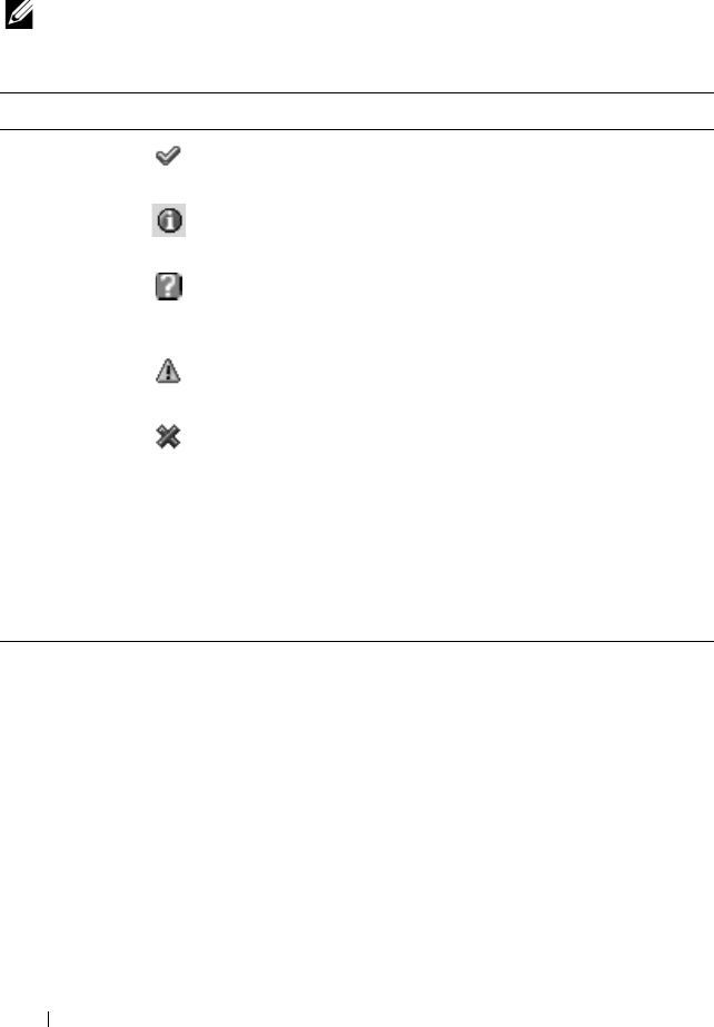
302 Troubleshooting and Recovery
To clear the hardware log:
Click Clear Log.
NOTE: The CMC creates a new log entry indicating that the log was cleared.
Using RACADM
1
Open a Telnet/SSH text console to the CMC and log in.
2
To view the hardware log, type:
racadm getsel
To clear the hardware log, type:
racadm clrsel
Table 11-8. Hardware Log Information
Item Description
Severity OK Indicates a normal event that does not require
corrective actions.
Informational Indicates an informational entry on an event in
which the Severity status has not changed.
Unknown Indicates a noncritical event for which
corrective actions should be taken soon to
avoid system failures.
Warning Indicates a critical event requiring immediate
corrective actions to avoid system failures.
Severe Indicates a critical event that requires
immediate corrective actions to avoid system
failures.
Date/Time Indicates the exact date and time the event occurred (for example,
Wed May 02 16:26:55 2007). If no date/time appears, then the
event occurred at System Boot.
Description Provides a brief description, generated by the CMC, of the event
(for example, Redundancy lost, Server inserted).

Troubleshooting and Recovery 303
Viewing the CMC Log
The CMC generates a log of chassis-related events.
NOTE: To clear the hardware log, you must have Clear Logs Administrator
privilege.
Using the Web Interface
You can view, save a text file version of, and clear the CMC log in the CMC
Web interface.
You can re-sort the log entries by Source, Date/Time, or Description by
clicking the column heading. Subsequent clicks on the column headings
reverse the sort.
Table 11-9 provides descriptions of the information provided on the CMC
Log page in the CMC Web interface.
To view the CMC log:
1
Log in to the CMC Web interface.
2
Click
Chassis
in the system tree.
3
Click the
Logs
tab.
4
Click the
CMC Log
sub-tab. The
CMC Log
page displays.
To save a copy of the CMC log to your managed station or network, click Save
Log. A dialog box opens; select a location for a text file of the log.
Table 11-9. CMC Log Information
Command Result
Source Indicates the interface (such as the CMC) that caused the event.
Date/Time Indicates the exact date and time the event occurred (for example,
Wed May 02 16:26:55 2007).
Description Provides a short description of the action, such as a login or a
logout, login failure, or clearing the logs. Descriptions are
generated by the CMC.

304 Troubleshooting and Recovery
Using RACADM
1
Open a Telnet/SSH text console to the CMC and log in.
2
To view the hardware log, type:
racadm getraclog
To clear the hardware log, type:
racadm clrraclog
Firmware Update Error Codes
The CMC log can also display error codes as part of the log information. The
table below contains the firmware update CMC log error codes.
Table 11-10. Firmware Update Error Codes
Error Class Error Value (Hex) Error Value (Decimal)
ERR_NO_PRIVILEGE 0x1400 5120
ERR_LOC_CMC_STATE 0x1401 5121
ERR_INV_TARG_LINK 0x1402 5122
ERR_ILLEGAL_CMC_STATE 0x1403 5123
ERR_MX_NULL_PARAM 0x1404 5124
ERR_CLASS_UNSUPPORTED 0x1405 5125
ERR_INAPPROPRIATE_REQUEST 0x1406 5126
ERR_MX_BAD_PARAM 0x1407 5127
ERR_INVALID_TARGET 0x1408 5128
ERR_URL_NOT_FOUND 0x1409 5129
ERR_CANCEL_PID_KILL 0x140A 5130
ERR_REROUTE_PEER 0x140B 5131
ERR_BAD_URL 0x140C 5132
ERR_PAYLOAD_TOO_BIG 0x140D 5133
ERR_BAD_IP_CONV 0X140E 5134
ERR_BAD_HDR_PARAM 0x140F 5135
ERR_BAD_FILENAME 0x1410 5136
ERR_TARGET_NOT_READY 0x1411 5137

Troubleshooting and Recovery 305
ERR_TFTP_GET_FAIL 0x1412 5138
ERR_WAITPID_FAIL 0x1413 5139
ERR_REBOOT_FAIL 0x1414 5140
ERR_UNSUPPORTED_PROTOCOL 0x1415 5141
BAD_FTP_PASSWORD 0x1416 5142
ERR_FORK_FAILED 0x1417 5143
ERR_MALLOC_ERROR 0x1418 5144
ERR_PEER_ABSENT 0x1419 5145
ERR_UPDATE_FAIL 0x141A 5146
ERR_OPEN_FILE_FAIL 0x141B 5147
ERR_IMAGE_FILE_NOT_ACCESSIBLE 0x141C 5148
ERR_FCNTL_GET_FAIL 0x141D 5149
ERR_FCNTL_SET_FAIL 0x141E 5150
ERR_POLL_FAIL 0x141F 5151
ERR_SEND_FAIL 0x1420 5152
ERR_CONNECT_FAIL 0x1421 5153
ERR_SOCKET_FAIL 0x1422 5154
ERR_RESOLVE_REMOTE_IP_ADDR_FAIL 0x1423 5155
ERR_TIMEOUT 0x1424 5156
ERR_RECV_FAIL 0x1425 5157
ERR_INVENTORY_COUNT 0x1426 5158
ERR_FWUPD_INIT_CALL 0x1427 5159
ERR_FWUPD_START_UPDATE_CALL 0x1428 5160
ERR_OP_NOT_CANCELABLE 0x1429 5161
BAD_FTP_USERNAME 0x142A 5162
DEVICE_NOT_AVAILABLE 0x142B 5163
Table 11-10. Firmware Update Error Codes (continued)
Error Class Error Value (Hex) Error Value (Decimal)

306 Troubleshooting and Recovery
Using the Diagnostic Console
The
Diagnostic Console
page enables an advanced user, or a user under the
direction of technical support, to diagnose issues related to the chassis
hardware using CLI commands.
NOTE: To modify these settings, you must have Debug Command Administrator
privilege.
To access the
Diagnostic Console
page:
1
Log in to the CMC Web interface.
2
Click
Chassis
in the system tree.
3
Click the
Troubleshooting
tab.
4
Click the
Diagnostics
sub-tab. The
Diagnostic Console
page displays.
To execute a diagnostic CLI command, type the command into the Enter
RACADM Command field, and then click Submit to execute the diagnostic
command. A diagnostic results page appears.
To return to the
Diagnostic Console
page, click Go Back to
Diagnostic
Console
Page or Refresh.
The Diagnostic Console supports the commands listed in Table 11-11 as well
as the RACADM commands.
Table 11-11. Supported Diagnostic Commands
Command Result
arp Displays the contents of the address resolution protocol (ARP)
table. ARP entries may not be added or deleted.
ifconfig Displays the contents of the network interface table.
netstat Prints the contents of the routing table.
ping <IP address> Verifies that the destination <IP address> is reachable from
the CMC with the current routing-table contents. You must
type a destination IP address in the field to the right of this
option. An Internet control message protocol (ICMP) echo
packet is sent to the destination IP address based on the
current routing-table contents.

Troubleshooting and Recovery 307
Interpreting LED Colors and Blinking Patterns
The LEDs on the chassis provide information by color and blinking/not
blinking:
• Steadily glowing, green LEDs indicate that the component is powered on.
If the green LED is blinking, it indicates a critical but routine event,
such as a firmware upload, during which the unit is not operational. It
does not indicate a fault.
• A blinking amber LED on a module indicates a fault on that module.
• Blue, blinking LEDs are configurable by the user and used for
identification (see "Configuring LEDs to Identify Components on the
Chassis" on page 285).
Table 11-12 lists common LED patterns on the chassis.
gettracelog Displays the trace log (may take a few seconds to display the
log). The gettracelog -i command returns the number of
records in the trace log. The gettracelog -A command returns
the trace log without the record numbers.
NOTE: This command is for Dell internal use only.
NOTE: For more information about the gettracelog command,
see "gettracelog" on page 359.
Table 11-12. LED Color and Blinking Patterns
Component LED Color, Blinking Pattern Meaning
CMC Green, glowing steadily Powered on
Green, blinking Firmware is being uploaded
Green, dark Powered off
Blue, glowing steadily Master/primary
Blue, blinking User-enabled module identifier
Amber, glowing steadily Not used
Amber, blinking Fault
Table 11-11. Supported Diagnostic Commands (continued)
Command Result

308 Troubleshooting and Recovery
Blue, dark Slave/standby
iKVM Green, glowing steadily Powered on
Green, blinking Firmware is being uploaded
Green, dark Powered off
Amber, glowing steadily Not used
Amber, blinking Fault
Amber, dark No fault
Server Green, glowing steadily Powered on
Green, blinking Firmware is being uploaded
Green, dark Powered off
Blue, glowing steadily Normal
Blue, blinking User-enabled module identifier
Amber, glowing steadily Not used
Amber, blinking Fault
Blue, dark No fault
IOM
(Common)
Green, glowing steadily Powered on
Green, blinking Firmware is being uploaded
Green, dark Powered off
Blue, glowing steadily Normal/stack master
Blue, blinking User-enabled module identifier
Amber, glowing steadily Not used
Amber, blinking Fault
Blue, dark No fault/stack slave
Table 11-12. LED Color and Blinking Patterns (continued)
Component LED Color, Blinking Pattern Meaning

Troubleshooting and Recovery 309
IOM (Pass
through)
Green, glowing steadily Powered on
Green, blinking Not used
Green, dark Powered off
Blue, glowing steadily Normal
Blue, blinking User-enabled module identifier
Amber, glowing steadily Not used
Amber, blinking Fault
Blue, dark No fault
Fan Green, glowing steadily Fan working
Green, blinking Not used
Green, dark Powered off
Amber, glowing steadily Fan type not recognized, update
CMC firmware
Amber, blinking Fan fault; tachometer out of range
Amber, dark Not used
PSU (Oval) Green, glowing steadily AC OK
(Oval) Green, blinking Not used
(Oval) Green, dark AC Not OK
Amber, glowing steadily Not used
Amber, blinking Fault
Amber, dark No fault
(Circle) Green, glowing
steadily
DC OK
(Circle) Green, dark DC Not OK
Table 11-12. LED Color and Blinking Patterns (continued)
Component LED Color, Blinking Pattern Meaning

310 Troubleshooting and Recovery
Troubleshooting a Non-responsive CMC
NOTE: It is not possible to log in to the standby CMC using a serial console.
If you cannot log in to the CMC using any of the interfaces (the Web
interface, Telnet, remote RACADM, or serial), you can verify CMC
functionality by observing the LEDs on the CMC, obtaining recovery
information using the DB-9 serial port, or recovering the CMC firmware
image.
Observing the LEDs to Isolate the Problem
Facing the front of the CMC as it is installed in the chassis, you will see two
LEDs on the left side of the card.
Top LED — The top green LED indicates power. If it is NOT on:
1
Verify that you have AC present to at least one power supply.
2
Verify that the CMC card is seated properly. You can release/pull on the
ejector handle, remove the CMC, reinstall the CMC making sure the
board is inserted all the way and the latch closes correctly.
Bottom LED — The bottom LED is multi-colored. When the CMC is active
and running, and there are no problems, the bottom LED is blue. If it is
amber, a fault was detected. The fault could be caused by any of the following
three events:
• A core failure. In this case, the CMC board must be replaced.
• A self-test failure. In this case, the CMC board must be replaced.
• An image corruption. In this case, you can recover the CMC by uploading
the CMC firmware image.
NOTE: A normal CMC boot/reset takes over a minute to fully boot into its OS and be
available for login. The blue LED is enabled on the active CMC. In a redundant, two-
CMC configuration, only the top green LED is enabled on the standby CMC.
Obtain Recovery Information From the DB-9 Serial Port
If the bottom LED is amber, recovery information should be available from
the DB-9 serial port located on the front of the CMC.

Troubleshooting and Recovery 311
To obtain recovery information:
1
Install a NULL modem cable between the CMC and a client machine.
2
Open a terminal emulator of your choice (such as HyperTerminal or
Minicom). Set up: 8 bits, no parity, no flow control, baud rate 115200.
A core memory failure will display an error message every 5 seconds.
3
Press <Enter>. If a
recovery
prompt appears, additional information is
available. The prompt will indicate the CMC slot number and failure type.
To display failure reason and syntax for a few commands, type
recover
and then press <Enter>. Sample prompts:
recover1[self test] CMC 1 self test failure
recover2[Bad FW images] CMC2 has corrupted images
• If the prompt indicates a self test failure, there are no serviceable
components on the CMC. The CMC is bad and must returned to
Dell.
• If the prompt indicates
Bad FW Images
, then follow the steps in
"Recovering the Firmware Image" on page 311 to fix the problem.
Recovering the Firmware Image
The CMC enters recover mode when a normal CMC OS boot is not possible.
In recover mode, a small subset of commands are available that allow you to
reprogram the flash devices by uploading the firmware update file,
firmimg.cmc. This is the same firmware image file used for normal firmware
updates. The recovery process displays its current activity and boots to the
CMC OS upon completion.
When you type recover and then press <Enter> at the recovery prompt,
the recover reason and available sub-commands display. An example recover
sequence may be:
recover getniccfg
recover setniccfg 192.168.0.120 255.255.255.0
192.168.0.1

312 Troubleshooting and Recovery
recover ping 192.168.0.100
recover fwupdate -g -a 192.168.0.100
NOTE: Connect the network cable to the left most RJ45
NOTE: In recover mode, you cannot ping the CMC normally because there is no
active network stack. The recover ping <TFTP server IP> command allows you to
ping to the TFTP server to verify the LAN connection. You may need to use the
recover reset command after setniccfg on some systems.
Troubleshooting Network Problems
The internal CMC Trace Log allows you to debug CMC alerting and
networking. You can access the trace log using the CMC Web interface (see
"Using the Diagnostic Console" on page 306) or RACADM (see "Using the
RACADM Command Line Interface" on page 69 and "gettracelog" on
page 359).
The trace log tracks the following information:
• DHCP — Traces packets sent to and received from a DHCP server.
• IP — Traces IP packets sent and received.
• DDNS — Traces dynamic DNS update requests and responses.
The trace log may also contain CMC firmware-specific error codes that are
related to the internal CMC firmware, not the managed system’s operating
system.
NOTE: The CMC will not echo an ICMP (ping) with a packet size larger than
1500 bytes.
Disabling a Forgotten Password
CAUTION: Many repairs may only be done by a certified service technician. You
should only perform troubleshooting and simple repairs as authorized in your
product documentation, or as directed by the online or telephone service and
support team. Damage due to servicing that is not authorized by Dell is not covered
by your warranty. Read and follow the safety instructions that came with the
product.

Troubleshooting and Recovery 313
To perform management actions, a user with Administrator privileges is
required. The CMC software has a user account password protection security
feature that may be disabled if the administrator account password is
forgotten. If the administrator account password is forgotten, it can be
recovered using the PASSWORD_RSET jumper on the CMC board.
The CMC board has a two-pin password reset connector as shown in
Figure 11-1. If a jumper is installed in the reset connector, the default
administrator account and password is enabled and set to the default values
of username: root and password: calvin. The administrator account will be
reset regardless if the account has been removed, or if the password was
changed.
NOTE: Make sure the CMC module is in a passive state before you begin.
1
Press in the CMC release latch on the handle and rotate the handle away
from the module front panel. Slide the CMC module out of the enclosure.
NOTE: Electrostatic discharge (ESD) events can harm electronic components
inside your equipment. Under certain conditions, ESD may build up on your body or
an object, and then discharge into another object, such as your CMC. To prevent
ESD damage, you should discharge static electricity from your body before you
interact with any of your equipment’s internal electronic components.
2
Remove the jumper plug from the password reset connector, and insert a 2-
pin jumper to enable the default administrator account. See Figure 11-1 to
locate the password jumper on the CMC board.
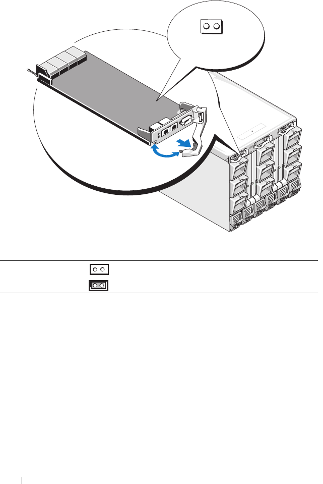
314 Troubleshooting and Recovery
Figure 11-1. Password Reset Jumper Location
3
Slide the CMC module into the enclosure. Reattach any cables that were
disconnected.
4
Initiate a changeover to make the module active using the GUI interface
to perform the following steps:
a
Navigate to the
Chassis
page, click the
Power Management
tab -
Control
sub tab.
b
Select the
Reset CMC (warm boot)
button.
c
Click
Apply
.
Table 11-13. CMC Password Jumper Settings
PASSWORD_RSET (default) The password reset feature is disabled.
The password reset feature is enabled.
PASSWORD_RSET

Troubleshooting and Recovery 315
5
The CMC automatically fails over to the redundant module, and that
module now becomes active. Log into the active CMC using the default
administrator username of
root
and password of
calvin,
and restore any
necessary user account settings. The existing accounts and passwords are
not disabled and are still active.
After you have completed any account updates, remove the 2-pin jumper and
replace the jumper plug.
NOTE: Make sure the CMC module is in a passive state before you begin.
1
Press in the CMC release latch on the handle and rotate the handle away
from the module front panel. Slide the CMC module out of the enclosure.
2
Remove the 2-pin jumper and replace the jumper plug.
3
Slide the CMC module into the enclosure. Reattach any cables that were
disconnected.
Troubleshooting Alerting
Use the CMC log and the trace log to troubleshoot CMC alerts. The success
or failure of each Email and/or SNMP trap delivery attempt is logged into the
CMC log. Additional information describing the particular error is logged in
the trace log. However, since SNMP does not confirm delivery of traps, use a
network analyzer or a tool such as Microsoft’s snmputil to trace the packets
on the managed system.
You can configure SNMP alerts using the Web interface. For information, see
"Configuring SNMP Alerts" on page 286.

316 Troubleshooting and Recovery

RACADM Subcommands 317
RACADM Subcommands
"?" and "? <command>"
NOTE: To use this subcommand, you must have CMC Login User privilege.
Description
? lists all of the subcommands you can use with the racadm command and a
one-line description of each subcommand.
? <command> displays the syntax for the specified command.
NOTE: You can also use the help and help <command> commands to obtain the
same information.
Usage
racadm ?
racadm ? <
command
>
Examples
NOTE: The following output example shows only part of the actual output for the
racadm ? command. Descriptions shown in this example may vary slightly from the
descriptions in your racadm session.
•
racadm ?
help -- list racadm subcommand
description
help <subcommand> -- display usage summary for a
subcommand
? -- list racadm subcommand
description
? <subcommand> -- display usage summary for a
subcommand
arp -- display the networking arp table
chassisaction -- execute chassis or switch
power-up/down/cycle or KVM powercycle

318 RACADM Subcommands
clrraclog -- clear the CMC log
clrsel -- clear the System Event Log (SEL)
cmcchangeover -- Changes the redundant state of
the CMC from active to standby and vice versa
config -- modify CMC configuration
properties
LEDs on a module
...
setniccfg -- modify network configuration
properties
setractime -- set the time on the CMC
setslotname -- sets the name of the slot in the
chassis
setsysinfo -- set the chassis name and chassis
location
sslcertview -- display a CA/server certificate
in the CMC
sslcsrgen -- generate a certificate CSR from
the CMC
testemail -- test CMC email notifications
testtrap -- test CMC SNMP trap notifications
•
racadm ? getsysinfo
getsysinfo -- display general CMC and system
information
Usage:
getsysinfo [-d] [-c] [-A]
-d : show cmc information
-c : show chassis information
-A : do not show headers or labels
arp
NOTE: To use this subcommand you must have Administrator privilege.
Description
Display the Address Resolution Protocol (ARP) table. This table stores the
mapping of IP numbers to MAC addresses of the NICs in the chassis.

RACADM Subcommands 319
Example
•
racadm arp
Address HWtype HWaddress Flags
Mask Iface
143.166.152.3 ether 00:07:84:A7:CE:BC C
eth0
143.166.152.2 ether 00:07:84:7B:9F:FC C
eth0
143.166.152.1 ether 00:00:0C:07:AC:0A
C eth0
143.166.152.113 ether 00:15:C5:48:9C:1D C
eth0
chassisaction
NOTE: To use this subcommand, you must have Chassis Control Administrator
privilege.
Description
Executes a power action on the chassis, iKVM, or a server.
Usage
racadm chassisaction [-m <
module
>] <
action
>
Options
Table A-1 describes chassisaction subcommand options.
Table A-1. chassisaction Subcommand Options
Option Description
-m <module> Specifies the module on which you want the action carried out.
<module> may be one of the following:
•
chassis
•
switch-
n
where
n
=1–6
•
kvm

320 RACADM Subcommands
Example
•
racadm chassisaction -m switch-3 reset
Module power operation successful.
clrraclog
NOTE: To use this subcommand, you must have Clear Logs Administrator privilege.
Description
Removes all existing records from the CMC log. A new log entry is added to
record the date and time when the log was cleared, and the user who cleared
the log.
NOTE: To view the CMC log, use getraclog. For information about the CMC log, see
"Viewing the CMC Log" on page 303.
Usage
racadm clrraclog
NOTE: The -A option is ignored and is supported to provide backward compatibility
for existing scripts.
Output
The CMC log was cleared successfully.
<action> Specifies the action you want to execute on the specified module.
<action> may be one of the following:
•
powerdown
— (Chassis only) Powers down the chassis.
•
powerup
— (Chassis only) Powers up the chassis.
•
powercycle
— Power cycles the module.
•
nongraceshutdown
— (Chassis only) Shutdown the chassis
non-gracefully.
•
reset
— Performs a hard reset of the module.
Table A-1. chassisaction Subcommand Options (continued)
Option Description

RACADM Subcommands 321
clrsel
NOTE: To use this subcommand, you must have Clear Logs Administrator privilege.
Description
Removes all existing records from the system events log (SEL, or hardware
log). A new log entry is added to record the date and time when the log was
cleared, and the user who cleared the log.
NOTE: To view the hardware log, use getsel. For information about the hardware
log, see "Viewing the Hardware Log" on page 300.
Usage
racadm clrsel
NOTE: The -A and -o options do not generate additional output and are supported
to provide backward compatibility for existing scripts.
Output
The SEL was cleared successfully.
cmcchangeover
NOTE: To use this subcommand, you must have Administrator privilege.
Description
Changes the state of the CMC from active to standby, or vice versa, in a
redundant CMC configuration. This subcommand is useful for remote
debugging or testing purposes.
NOTE: This command is valid only in redundant CMC environments. For more
information, see "Understanding the Redundant CMC Environment" on page 55.
Usage
racadm cmcchangeover
Output
CMC failover initiated successfully.

322 RACADM Subcommands
config
NOTE: To use this subcommand, you must have Chassis Configuration
Administrator privilege.
Description
Sets the CMC configuration parameters individually or in a batch as part of a
configuration file. If the data is different, that CMC object is written with the
new value.
Usage
racadm config -g <
group
> -o <
object
> <
value
>
racadm config -g <
group
> -o <
object
> -i <
index
>
<
value
>
racadm config -f <
filename
>
Options
Table A-2 describes the config subcommand options.
Table A-2. config Subcommand Options
Option Description
-g <group> Specifies the group containing the object that is to be set. Must
be used with the -o option. Table A-3 lists the group names that
may be specified with this option.
-o <object> Specifies the object name that is written with the string
<value>. Must be used with the -g option.
-i <index> Specifies a unique group name. Only valid for indexed groups.
The index is specified here by the index value (a decimal integer
from 1–16).
<value> Indicates the value to which you want the specified object set.
-f <filename> Specifies the file name to use as a configuration source.

RACADM Subcommands 323
Property Groups
NOTE: Appendix B, "CMC Property Database Group and Object Definitions" on
page 385, provides details about the property groups. See also "getconfig" on
page 332.
Table A-3 lists the property groups that can be specified with the -g option.
.
Table A-3. RACADM Property Groups
Group Description
cfgLanNetworking Configures network related properties
cfgRemoteHosts Enables/disables and configures firmware updates and
SMTP email alerting
cfgUserAdmin Configures CMC users
cfgEmailAlert Configures CMC email alerting
cfgSessionManagement Sets the maximum number of remote sessions allowed to
connect to CMC at a time
cfgSerial Enables/disables and configures serial console
cfgNetTuning Configures CMC network tuning
cfgOobSnmp Enables/disables and configures SNMP traps for the CMC
cfgTraps Displays information for and configures delivery of SNMP
traps for a specific user
cfgAlerting Enables or disables SNMP event trap alerting and sets the
event filter
cfgRacTuning Configures CMC tuning parameters
cfgRacSecurity Configures settings related to the CMC SSL certificate
signing request (CSR) feature
cfgActiveDirectory Configures Microsoft® Active Directory® properties
cfgStandardSchema Configures the Standard Schema settings for Active
Directory
cfgChassisPower Configures power for the chassis
cfgServerInfo Configures a server in the chassis
cfgKVMInfo Displays information for and configures the iKVM

324 RACADM Subcommands
Output
The config subcommand generates error output when it encounters any of
the following:
• Invalid syntax, group name, object name, index, or other invalid database
members
• Insufficient user privileges
• RACADM CLI failures
•The
config
subcommand returns an indication of how many configuration
objects were written out of how many total objects were in the .cfg file.
Examples
•
racadm config -g cfgLanNetworking -o
cfgNicIpAddress 10.35.10.100
Sets the
cfgNicIpAddress
configuration parameter (object) to the value
10.35.10.110. This IP address object is contained in the group
cfgLanNetworking
(see "cfgLanNetworking" on page 387).
•
racadm config -f myrac.cfg
Configures or reconfigures the CMC. You can create the
myrac.cfg
file
using the
getconfig
command. You can also manually edit the
myrac.cfg
file, as long as you adhere to the parsing rules (see "Parsing Rules" on
page 87).
NOTE: The myrac.cfg file does not contain password information. To include this
password information in the file, you must input it manually.
deploy
NOTE: To use this subcommand, you must have Server Administrator privilege.
Description
Configures the static IP address, subnet mask, gateway, and password for the
root user on the iDRAC for the specified server.

RACADM Subcommands 325
NOTE: This subcommand is valid only if the DHCP option is disabled for the
specified server. When DHCP is enabled, the server automatically obtains an IP
address, subnet mask, and gateway from the DHCP server. To determine whether
DHCP is enabled for the server, use getniccfg (see "getniccfg" on page 345). To
enable or disable DCHP, use setniccfg (see "setniccfg" on page 373).
NOTE: You can also use setniccfg to configure static IP address, subnet mask, and
gateway, as well as DHCP, speed, and duplex properties. For more information, see
"setniccfg" on page 373.
Usage
racadm deploy -m <module> -u root -p <password>
[-s <ipaddress> <subnet> <gateway>] [-d]
Options
Table A-4 describes the deploy subcommand options.
Table A-4. deploy Subcommand Options
Option Description
-u root Indicates that the <password> will be supplied
for the root user on the server. root is a constant
parameter, the only value that is valid with the -u
option.
-m <module> Specifies the server you want to configure.
Legal values: server-
n
, where
n
=1–16
-p <password> Specifies the password for the root user on the
server.
-s <ipaddress subnet gateway> Sets the IP address, subnet mask, and gateway for
the specified server, separated by single spaces.
•
ipaddress —
A string representing a valid IP
address. For example, 192.168.0.20.
•
subnet —
A string representing a valid subnet
mask. For example, 255.255.255.0.
•
gateway —
A string representing a valid subnet
mask. For example, 192.168.0.1.
-d Enables DHCP for the specified server.

326 RACADM Subcommands
Example
•
racadm deploy server-8 -s 192.168.0.20
255.255.255.0 192.168.0.1
The server was deployed successfully.
NOTE: The deploy command generates an error when used on the extension
slot of a multi-slot server.
•
racadm deploy -m server-9 192.168.0.11
255.255.255.0 192.168.0.1
ERROR: Server in slot 9 is an extension of the
server in slot 1.
feature
NOTE: To use this subcommand to deactivate FlexAddress, you must have Chassis
Configuration Administrator privilege. A user with login privileges can view status
only.
Description
Displays all active chassis features. The information displayed includes
feature name, date activated, and the serial number of the SD card used to
activate the feature.
NOTE: The feature subcommand must be run while the chassis is powered off to
deactivate FlexAddress or the command will return an error.
Usage
racadm feature [-s] [-d -c <featurename>]
<featurename> = FlexAddress
Options
Table A-5 describes the feature subcommand options.

RACADM Subcommands 327
Example
•racadm feature -d -c flexaddress
feature FlexAddress is deactivated on the chassis
successfully
•racadm feature -s
Feature = FlexAddress
Date Activated = 8 April 2008 - 10:39:40
Feature installed from SD card SN = 01122334455
featurecard
NOTE: To use this subcommand, you must have Chassis Configuration
Administrator privilege.
Description
Verifies proper SD card installation and displays SD card status. The table
below lists the status messages returned by the command.
Table A-5. feature Subcommand Options
Option Description
-d -c
<featurename>
Deactivates feature.
-s Lists active features.

328 RACADM Subcommands
Usage
racadm featurecard -s
Options
Table A-7 describes the featurecard subcommand options.
Table A-6. Status Messages Returned by featurecard -s Command
Status Message Actions
No feature card inserted. Check the CMC to verify that the SD card
was properly inserted. In a redundant CMC
configuration, make sure the CMC with the
SD feature card installed is the active CMC
and not the standby CMC.
The feature card inserted is valid and
contains the following feature(s)
FlexAddress: The feature card is
bound to this chassis
No action required.
The feature card inserted is valid and
contains the following feature(s)
FlexAddress: The feature card is
bound to another chassis,
svctag = ABC1234, SD card
SN = 01122334455
Remove the SD card; locate and install the SD
card for the current chassis.
The feature card inserted is valid and
contains the following feature(s)
FlexAddress: The feature card is not
bound to any chassis
The feature card can be moved to another
chassis, or can be reactivated on the current
chassis. To reactivate on the current chassis,
enter
racadm racreset
until the CMC
module with the feature card installed
becomes active.
Table A-7. featurecard Subcommand Options
Option Description
-s Lists active SD card features and SD card status.

RACADM Subcommands 329
Example
racadm featurecard -s
•racadm featurecard -s
The feature card inserted is valid and contains
the following feature(s) FlexAddress: The feature
card is bound to this chassis
fwupdate
NOTE: To use this subcommand, you must have Chassis Configuration
Administrator privilege.
Description
Updates the firmware on the iKVM, primary CMC, (if applicable) the
standby CMC, the server iDRAC, and the IOM infrastructure device. Also
performs updates to iDRAC firmware when the existing firmware is
corrupted.
NOTE: Running the fwupdate subcommand to update the firmware on the primary
CMC causes all Telnet and Web connections to be dropped. To monitor the progress
of the update, use the -s option. During update of all other modules, including the
standby CMC, the primary CMC continues to run normally without resetting.
NOTE: The fwupdate subcommand may only be executed on one device at a time
for the iKVM. The CMCs, servers, and IOM infrastructure devices can have multiple
devices updated with the same action.
Usage
racadm fwupdate -g -u -a <
tftp server ip address
> {-f
<
ftp server ip address
> <
username
> <
password>
} -d
<
path
> -m <
target
>
racadm fwupdate -s
racadm fwupdate -c
Options
Table A-8 describes the fwupdate subcommand options.

330 RACADM Subcommands
NOTE: Wait for the file to finish transferring from the TFTP server before you check
the status of the update.
NOTE: When using FTP, if the full path to the image file is provided on the CLI, then
that path is used to locate that file on the host. If a path is not provided, then the
home directory of the specified user is searched for the file if the host system is
running Linux or some other variant of UNIX. If the host system is running Windows,
the a default folder (like ftproot) is searched.
Table A-8. fwupdate Subcommand Options
Option Description
-d <path> Specifies the source path where the firmware image resides.
Default: local directory on CMC if -g option is absent. If -g is
used, defaults to directory configured on the TFTP server
-g Downloads the firmware update using the TFTP server.
-u Performs firmware update operation (used with -g).
-a <tftp server ip
address>
Specifies the TFTP server IP address used for the firmware image
(used with -g).
-f <ftp server ip
address>
<username>
<password>
Specifies the FTP server IP address used for the firmware image,
along with the username and password. Can only be used with
CMC, iKVM, and server iDRAC target devices.
-m <target> Specifies the target, or device, to be updated. <target> is one of
the following values:
•
cmc-active
(default)
•
cmc-standby
•
kvm
•
server-
n
where
n
= 1–16
•
iomifn-
n
where
n
= 1–6
NOTE: The cmc-active and cmc-standby targets can be
entered together, as well as one or more server-n, and one or
more iomifn-n targets so that those devices can be updated
together.
-s Displays the current status of the firmware update.
-c Cancels the current firmware update.

RACADM Subcommands 331
Example
•
racadm fwupdate -g -u -a 192.168.0.120 -d
firmimg.cmc -m cmc-active
TFTP firmware update has been initiated. This
update process may take several minutes to
complete.
Firmware update complete.
•
racadm fwupdate -s -m cmc-active
Firmware update in progress.
NOTE: The fwupdate command generates an error when used on the
extension slot of a multi-slot server.
•
racadm fwupdate -g -u -a 192.168.0.120 -d update -
m server-9
ERROR: Server in slot 9 is an extension of the
server in slot 1.
getassettag
NOTE: To use this subcommand, you must have CMC Login User privilege.
Description
Displays the asset tag for the chassis.
Usage
racadm getassettag [-m <
module
>]
Options
Table A-9 describes the getassettag subcommand options.

332 RACADM Subcommands
Example
•
racadm getassettag -m chassis
or
racadm getassettag
chassis 78373839–33
getchassisname
NOTE: To use this subcommand, you must have CMC Login User privilege.
Description
Displays the name of the chassis.
Usage
racadm getchassisname
Example
•
racadm getchassisname
PowerEdge 2955
getconfig
NOTE: To use this subcommand, you must have Chassis Configuration
Administrator privilege.
Table A-9. getassettag Subcommand Options
Option Description
-m <module> Specifies the module whose asset tag you want to view.
Legal value: chassis
Because there is only one legal value, you can obtain the same
output if you do not include this option.

RACADM Subcommands 333
Description
Displays CMC configuration parameters and allows you to save CMC
configuration groups to a .cfg file.
Usage
racadm getconfig -g <
groupName
>
racadm getconfig -g <
groupName
> -o <
object
>
racadm getconfig -g <
groupName
> -i <
index
>
racadm getconfig -u <
username
>
racadm getconfig -h
racadm getconfig -f <
filename
>
Options
Table A-10 describes the getconfig subcommand options.
Property Groups
NOTE: "CMC Property Database Group and Object Definitions" on page 385,
provides details about these property groups. See also "config" on page 322.
Table A-10. getconfig Subcommand Options
Option Description
-g <groupName> Specifies the group containing the object that is to be set.
Must be used with the -o option.Table A-11 lists the groups
you can specify.
-o <objectName> Specifies the object name that is written with the string
<value>. Must be used with the -g option.
-i <index> Specifies a unique group name. Only valid for indexed groups.
The index is specified by the index value (a decimal integer
from 1–16).
-u Displays the group associated with a specific user.
-h Displays a list of available configuration groups.
-f <filename> Saves CMC configuration in a .cfg. file using the specified file
name.

334 RACADM Subcommands
Table A-11 lists the property groups that can be specified with the getconfig
subcommand -g option.
Table A-11. Property Groups for the getconfig Subcommand
Property Group Description
idRacInfo (read only) Displays version, build number, and product
information for the CMC.
cfgLanNetworking Configures network related properties.
cfgCurrentLanNetworking
(read only)
Displays the current CMC NIC properties.
cfgRemoteHosts Enables/disables and configures firmware updates
and SMTP email alerting.
cfgUserAdmin Configures CMC users.
cfgEmailAlert Configures SMTP email alerts.
cfgSessionManagement Sets the maximum number of remote sessions
allowed to connect to CMC at a time.
cfgSerial Enables/disables and configures serial console.
cfgNetTuning Configures CMC network tuning.
cfgOobSnmp Enables/disables and configures SNMP traps for the
CMC.
cfgTraps Configures delivery of SNMP traps for a specific user.
cfgAlerting Enables or disables SNMP event trap alerting and
sets the event filter.
cfgRacTuning Configures CMC tuning parameters.
cfgRacSecurity Configures settings related to the CMC SSL
certificate signing request (CSR).
cfgActiveDirectory Configures Microsoft Active Directory properties.
cfgStandardSchema Configures the Standard Schema settings for Active
Directory.
cfgChassisPower Configures power for the chassis
cfgServerInfo Configures a server in the chassis
cfgKVMInfo Displays information for and configures the iKVM

RACADM Subcommands 335
Output
This subcommand generates error output upon encountering either of the
following:
• Invalid syntax, group name, object name, index, or other invalid database
members
• RACADM CLI transport failures
If errors are not encountered, this subcommand displays the contents of the
specified configuration.
Examples:
•
racadm getconfig -g cfgLanNetworking
Displays all of the configuration properties (objects) that are contained in
the group
cfgLanNetworking
(see "cfgLanNetworking" on page 387).
•racadm getconfig -g cfgserverinfo -o cfgservername
123456789012345
Saves the server slotname; the slotname can have a maximum of 15
characters (see "cfgServerName" on page 419).
•racadm getconfig -f myrac.cfg
Saves all group configuration objects from the CMC to
myrac.cfg
.
•
racadm getconfig -h
Displays a list of the available configuration groups on the CMC.
•
racadm getconfig -u root
Displays the configuration properties for the user named root.
getdcinfo
NOTE: To use this subcommand, you must have CMC Login User privilege.
Description
Displays general I/O module and daughter card configuration information.

336 RACADM Subcommands
NOTE: Fabric verification for server DCs is performed only when the chassis is
powered on. When the chassis is on standby power, the iDRACs on the server
modules remain powered off and thus are unable to report the server's DC fabric
type. The DC fabric type may not be reported in the CMC user interface until the
iDRAC on the server is powered on.
Usage
racadm getdcinfo
NOTE: The example output below is for a system with multi-slot servers.
Example
•
racadm getdcinfo
Group 1 I/O Type : Gigabit Ethernet
Group 2 I/O Type : FibreChannel 8
Group 3 I/O Type : Infiniband DDR
<IO#> <Type> <State>
switch-1 Gigabit Ethernet OK
switch-2 Gigabit Ethernet OK
switch-3 FibreChannel 8 OK
switch-4 FibreChannel 8 OK
switch-5 Infiniband DDR OK
switch-6 Infiniband DDR OK
<Server#> <Presence> <DC1 Type> <DC1 State>
<DC2 Type> <DC2 State>
server-1 Present FibreChannel 8 OK
Infiniband DDR OK
server-2 Not Present None N/A
None N/A
server-3 Present FibreChannel 8 OK
Infiniband DDR OK
server-4 Not Present None N/A
None N/A
server-5 Not Present None N/A
None N/A
server-6 Not Present None N/A
None N/A
server-7 Not Present None N/A
None N/A

RACADM Subcommands 337
server-8 Not Present None N/A
None N/A
server-9 Extension(1) FibreChannel 8 OK
Infiniband DDR OK
server-10 Not Present None N/A
None N/A
server-11 Not Present None N/A
None N/A
server-12 Not Present None N/A
None N/A
server-13 Not Present None N/A
None N/A
server-14 Not Present None N/A
None N/A
server-15 Not Present None N/A
None N/A
server-16 Not Present None N/A
None N/A
getflexaddr
NOTE: To use this subcommand, you must have CMC Login User privilege.
Description
Displays enabled/disabled status for the entire chassis. If used with -i, the
command displays MACs/WWN on a per slot basis.
NOTE: If FlexAddress is not activated on the chassis, the command displays
server-assigned MAC/WWN addresses. If the slot is empty, the command will
return an error message.
Usage
racadm getflexaddr [-i <slot#>]
<slot#> = 1 to 16
Options
Table A-12 describes the getflexaddr subcommand options.

338 RACADM Subcommands
Example
•racadm getflexaddr
<Slot#> <SlotName> <Status>
1 slot-1 enabled
2 slot-2 enabled
3 slot-3 disabled
4 slot-4 disabled
5 slot-5 disabled
6 slot-6 disabled
7 slot-7 disabled
8 slot-8 disabled
9 slot-9 disabled
10 slot-10 disabled
11 slot-11 disabled
12 slot-12 disabled
13 slot-13 disabled
14 slot-14 disabled
15 slot-15 disabled
16 slot-16 disabled
<Fabric> <Type> <Status>
Fabric-A ethernet disabled
Table A-12. getflexaddr Subcommand Options
Option Description
-i Specifies the slot information to be displayed.

RACADM Subcommands 339
Fabric-B iSCSI enabled
Fabric-C fiber channel enabled
•racadm getflexaddr -i 1
Slot-1 flexaddress enabled = 1
<Fabric> <Type> <Server-Assigned>
<Chassis-Assigned>
slot1-A1 Gigabit Ethernet 00:1C:23:CD:AC:D2(active)
00:1E:C9:FF:E3:21
iSCSI 00:1C:23:CD:AC:D3(active)
00:1E:C9:FF:E3:22
slot1-A2 Gigabit Ethernet 00:1C:23:CD:AC:D4(active)
00:1E:C9:FF:E3:23
iSCSI 00:1C:23:CD:AC:D5(active)
00:1E:C9:FF:E3:24
slot1-B1 Gigabit Ethernet 00:1D:09:71:B3:60
00:1E:C9:FF:E3:25(active)
iSCSI 00:1D:09:71:B3:61
00:1E:C9:FF:E3:26(active)
slot1-B2 Gigabit Ethernet 00:1D:09:71:B3:62
00:1E:C9:FF:E3:27(active)
iSCSI 00:1D:09:71:B3:63
00:1E:C9:FF:E3:28(active)
slot1-C1 Fiber Channel 4 10:00:00:00:C9:63:51:0E
20:01:00:1E:C9:FF:E3:29(active)
slot1-C2 Fiber Channel 4 10:00:00:00:C9:63:51:0D
20:02:00:1E:C9:FF:E3:29(active)
getioinfo
NOTE: To use this subcommand, you must have CMC Login User privilege.
Description
Displays general information about the I/O modules on the chassis.
NOTE: The fabric type may be any supported I/O fabric type, such as Ethernet,
Fiber Channel, and Infiniband.
Usage
racadm getioinfo

340 RACADM Subcommands
Example
racadm getioinfo
<IO> <Name> <Type> <presence>
<POST> <Power>
switch-1 Ethernet Passthrough Gigabit Ethernet Present
OK ON
switch-2 N/A None Not Present
N/A N/A
switch-3 N/A None Not Present
N/A N/A
switch-4 N/A None Not Present
N/A N/A
switch-5 N/A None Not Present
N/A N/A
switch-6 N/A None Not Present
N/A N/A
getkvminfo
NOTE: To use this subcommand, you must have CMC Login User privilege.
Description
Displays iKVM module information.
Usage
racadm getkvminfo
Example
racadm getkvminfo
<module> <presence> <model> <FW Version> <status>
KVM Present Avocent iKVM Switch 00.05.00.04 Ready
getled
NOTE: To use this subcommand, you must have CMC Login User privilege.

RACADM Subcommands 341
Description
Displays the LED settings on a module: blinking, not blinking, or unknown
(for empty slots).
Usage
racadm getled -m <
module
>
Table A-13 describes the getled subcommand options.
Examples
•
racadm getled -m server-10
<module> <state>
server-10 Blinking
•
racadm getled -m chassis
<module> <state>
server-10 Not blinking
•
racadm getled -m server-1
<module> <state>
server-1 ON
racadm getled -m server-9
<module> <state>
server-9 Extension(1)
Table A-13. getled Subcommand Options
Option Description
-m <module> Specifies the module whose LED
settings you want to view.
<module> can be one of the
following:
•
server-
n
where
n
=1–16
•
switch-
n
where
n
=1–6
•
chassis
•
cmc-active

342 RACADM Subcommands
getmacaddress
NOTE: To use this subcommand, you must have CMC Login User privilege.
Description
Displays the MAC/WWN addresses for all modules or for a specified module.
Usage
racadm getmacaddress [-m <
module
>] [<-t iscsi]
racadm getmacaddress [-a]
Options
Table A-14 describes the getmacaddress subcommand options.
Example
racadm getmacaddress -m server-1
<Name> <Presence> <BMC MAC Address> <NIC1 MAC Address>
<NIC2 MAC Address>
server-1 Present 00:11:43:FD:B7:2A 00:11:43:FD:B7:2A
Table A-14. getmacaddress Subcommand Options
Option Description
-m <module> Specifies the module whose MAC address you want to view.
<module> may be one of the following:
• chassis
•
server-
n
where
n=
1–16
•
switch-
n
where
n
=1–6
-t Displays the iSCSI MAC addresses for all servers or the specified
server if used with -m option.
-a Displays the Ethernet and iSCSI MAC/WWN addresses for all
iDRAC/LOMs/mezzanine cards. When FlexAddress is enabled for
a particular slot, then the chassis-assigned MAC/WWN address is
displayed.

RACADM Subcommands 343
00:11:43:FD:B7:2B
server-9 Extension(1) N/A 00:11:43:FD:B7:2C
00:11:43:FD:B7:2D
getmodinfo
NOTE: To use this subcommand, you must have CMC Login User privilege.
The service tag field is blank for modules that do not have service tags.
Description
Displays configuration and status information for all modules or a specified
module (server, switch, CMC, fan unit, or power supply unit) in the chassis.
Usage
racadm getmodinfo [-m <
module
>] [-A]
Options
Table A-15 describes the getmodinfo subcommand options.
Table A-15. getmodinfo Subcommand Options
Option Description
-m <module> Specifies the module whose configuration and status information
you want to view. The default command (no options) displays
information about all major components in the chassis.
<module> may be any of the following values:
•
server-
n
where
n
=
1–16
•
switch-
n
where
n
=
1–6
•
CMC-
n
where
n
=
1 (primary), 2 (standby)
•
fan-
n
where
n
=
1–9
•
ps-
n
where
n
=
1–6
•
kvm
•
chassis
-A Suppresses headers and labels in the output.

344 RACADM Subcommands
Example
•racadm getmodinfo -m switch-1
<module> <presence> <pwrState> <health> <svcTag>
Switch-1 Present ON OK ABC1234
•racadm getmodinfo
<module> <presence> <pwrState> <health> <svcTag>
Chassis Present ON Not OK ABC1234
Fan-1 Present ON OK
Fan-2 Present ON OK
Fan-3 Present ON OK
Fan-4 Present ON OK
Fan-5 Present ON OK
Fan-6 Present ON OK
Fan-7 Present ON OK
Fan-8 Present ON OK
Fan-9 Present ON OK
PS-1 Present Online OK
PS-2 Not Present N/A N/A N/A
PS-3 Present Online OK
PS-4 Not Present N/A N/A N/A
PS-5 Not Present N/A N/A N/A
PS-6 Not Present N/A N/A N/A
CMC-1 Present Primary OK N/A
CMC-2 Not Present N/A N/A N/A
Switch-1 Not Present N/A N/A N/A
Switch-2 Not Present N/A N/A N/A
Switch-3 Not Present N/A N/A N/A
Switch-4 Not Present N/A N/A N/A
Switch-5 Not Present N/A N/A N/A
Switch-6 Not Present N/A N/A N/A
Server-1 Not Present N/A N/A N/A
Server-2 Present OFF OK
Server-3 Present ON OK S YW
Server-4 Present ON OK
Server-5 Present ON OK
Server-6 Present ON OK 1234567
Server-7 Present ON OK
Server-8 Not Present N/A N/A N/A
Server-9 Not Present N/A N/A N/A
Server-10 Extension(2) N/A N/A N/A
Server-11 Not Present N/A N/A N/A
Server-12 Present ON OK
Server-13 Not Present N/A N/A N/A
Server-14 Present ON OK 0000015

RACADM Subcommands 345
Server-15 Present ON OK
Server-16 Present ON OK
KVM Present ON OK
getniccfg
NOTE: To use this subcommand, you must have CMC Login User privilege.
Description
Displays network settings for a server, switch, or the chassis.
NOTE: The getniccfg subcommand will display an error message if the operation is
not successful.
Usage
racadm getniccfg [-m <
module
>]
Options
Table A-16 describes the getniccfg subcommand options.
Examples
racadm getniccfg
NIC Enabled = 1
DHCP Enabled = 1
Static IP Address = 192.168.0.120
Static Subnet Mask = 255.255.255.0
Table A-16. getniccfg Subcommand Options
Option Description
-m <module> Specifies the module whose network settings you want to view.
<module> may be any of the following:
•
chassis
•
server-
n
where
n
=1–16
•
switch-
n
where
n
=1–6
Default: chassis

346 RACADM Subcommands
Static Gateway = 192.168.0.1
Current IP Address = 10.35.155.160
Current Subnet Mask = 255.255.255.0
Current Gateway = 10.35.155.1
Speed = Autonegotiate
Duplex = Autonegotiate
•
racadm getniccfg -m server-1
DHCP Enabled = 0
IP Address = 192.168.0.135
Subnet Mask = 255.255.255.0
Gateway = 192.168.0.1
•
racadm getniccfg -m server-9
ERROR: Server in slot 9 is an extension of the
server in slot 1.
getpbinfo
NOTE: To use this subcommand, you must have CMC Login User privilege.
Description
Displays power budget status information.
Usage
racadm getpbinfo
Example
racadm getpbinfo
[Power Budget Status]
System Input Power = 700 W
Peak System Power = 0 W
Peak System Power Timestamp = 01:08:23 01/27/2009
Minimum System Power = 0 W
Minimum System Power Timestamp = 20:18:30 01/27/2000
Overall Power Health = Not OK
Redundancy = No
System Input Power Cap = 7928 W

RACADM Subcommands 347
Redundancy Policy = None
Dynamic PSU Engagement Enabled = No
System Input Max Power Capacity = 0 W
Input Redundancy Reserve = 0 W
Input Power Allocated to Servers = 0 W
Input Power Allocated to Chassis Infrastructure =
51 watts
Total Input Power Available for Allocation = 0 W
Standby Input Power Capacity = 0 W
[Chassis Power Supply Status Table]
<Name> <Presence> <Power State> <Input Current> <Input Volts>
<Output Rating>
PS1 Online On 16.1 A 32 V
2360 W
PS2 Not Present Slot Empty N/A N/A
N/A
PS3 Not Present Slot Empty N/A N/A
N/A
PS4 Not Present Slot Empty N/A N/A
N/A
PS5 Not Present Slot Empty N/A N/A
N/A
PS6 Not Present Slot Empty N/A N/A
N/A
[Server Module Power Allocation Table]
<Slot#><Server Name><PowerState><Allocation><Priority><Blade Type>
1 SLOT-01 N/A N/A 5 N/A
2 SLOT-02 OFF 0 W 5 PowerEdgeM805
3 SLOT-03 ON 164 W 5 N/A
4 SLOT-04 ON 155 W 5
5 SLOT-05 ON 180 W 5
6 SLOT-06 ON 180 W 5 PowerEdgeM600
7 SLOT-07 ON 170 W 5
8 SLOT-08 N/A N/A 5 N/A
9 SLOT-09 N/A N/A 5 N/A
10 SLOT-10 Extension(2) N/A 5 N/A
11 SLOT-11 N/A N/A 5 N/A
12 SLOT-12 ON 125 W 5 PowerEdgeM600

348 RACADM Subcommands
13 SLOT-13 N/A N/A 5 N/A
14 SLOT-14 ON 342 W 5 N/A
15 SLOT-15 ON 140 W 5
16 SLOT-16 ON 125 W 5 N/A
getpminfo
NOTE: To use this subcommand, you must have CMC Login User privilege.
Description
Displays power management status information.
Usage
racadm getpminfo
Example
racadm getpminfo
[Real-Time Power Statistics]
System Input Power = 600 W (188 BTU/hr)
Peak System Power = 600 W (188 BTU/hr
Peak System Power Start Time = 16:02:10 01/16/2008
Peak System Power Timestamp = 06:32:55 01/26/2009
Minimum System Power = 400 W (177 BTU/hr)
Minimum System Power Start Time = 22:43:21 01/21/2008
Minimum System Power Timestamp = 06:32:55 01/26/2009
System Idle Power = 68 W (188 BTU/hr)
System Potential Power = 68 W (188 BTU/hr)
System Input Current Reading = 31.2 A
[Real-Time Energy Statistics]
System Energy Consumption = 6.4 kWh
System Energy Consumption Start Time = 16:02:10
01/16/2008
System Energy Consumption Timestamp = 16:02:10
01/16/2008
[System Power Status]

RACADM Subcommands 349
Overall Power Health = OK
Redundancy = No
[System Power Policy Configuration]
System Input Power Cap = 7928 W (7928
BTU/hr | 10%)
Surplus for Peak Performance = 7000 W (6130
BTU/hr)
Redundancy Policy = None
Dynamic PSU Engagement Enabled = No
[Power Budgeting]
System Input Max Power Capacity = 0 W
Input Redundancy Reserve = 0 W
Input Power Allocated to Servers = 0 W
Input Power Allocated to Chassis Infrastructure = 51W
Total Input Power Available for Allocation = 0 W
Standby Input Power Capacity = 0 W
getraclog
NOTE: To use this subcommand, you must have CMC Login User privilege.
Description
Displays the CMC log entries. The timestamp begins at midnight, January 1
and increases until the system boots. After the system boots, the system’s
timestamp is used.
Usage
racadm getraclog [-i]
racadm getraclog [-s <
start record
>] [-c <
count
>]
[-m]
Options
Table A-17 describes the getraclog subcommand options.

350 RACADM Subcommands
NOTE: The -A and -o options do not generate additional output and are supported
to provide backward compatibility for existing scripts.
Examples
•
racadm getraclog -c 5
Apr 21 10:17:46 cmc : CMC1: active
Apr 21 10:17:46 cmc : CMC1: AC power up
Apr 21 10:17:48 cmc : CMC1: non redundant
Apr 21 12:17:48 cmc : Login success (username =
root)
Apr 23 23:59:11 cmc : session close PID 3291
succeeds
•
racadm getraclog -i
Total Records: 171
getractime
NOTE: To use this subcommand, you must have CMC Login User privilege.
Description
Displays the date and time as currently set on the CMC.
Table A-17. getraclog Subcommand Options
Open Description
(none) Displays the entire CMC log, including the record number, time
stamp, source, and description of each event.
-s <start record> Specifies the starting record used for the display
-c <count> Specifies the maximum number of entries to be returned.
-i Displays the number of entries in the CMC log.
-m Displays one screen of information at a time and prompts the
user to continue to next screen (similar to the UNIX more
command).

RACADM Subcommands 351
Usage
racadm getractime [-d] [-z]
Options
Table A-18 describes the getractime subcommand options.
Examples
•
racadm getractime
Thu Dec 8 20:15:26 2005
•
racadm getractime -z
Thu Dec 8 20:15:29 2006 CST6CDT
•
racadm getractime -d
0051208201542.000000
getredundancymode
NOTE: To use this subcommand, you must have CMC Login User privilege.
Description
Displays the redundancy status (Redundant or Non-Redundant) of the
CMC.
Table A-18. getractime Subcommand Options
Option Description
(None) Displays the date and time using the same format as the UNIX® date
command.
-d Displays the date and time as a sequence of numeric digits, in the
following format: YYYYMMDDhhmmss.
-z Appends the current active time zone name to the display. For example,
PST8PDT (Western United States), 279 (Seoul), 329 (Sydney).
For a listing of all time zones supported by CMC, type:
racadm setractime -z *

352 RACADM Subcommands
Usage
racadm getredundancymode
Example
racadm getredundancymode
Redundant
getsel
NOTE: To use this subcommand, you must have CMC Login User privilege.
Description
Displays the system event log (SEL, also called the hardware log) entries. The
default output display shows the record number, timestamp, severity, and
description of each event.
Usage
racadm getsel [-i]
racadm getsel [-s <
start record
>] [-c <
count
>] [-m]
NOTE: The -A and -o options do not generate additional output and are supported
to provide backward compatibility for existing scripts.
Options
Table A-19 describes the getsel subcommand options.
Table A-19. getsel Subcommand Options
Option Description
-s <start record> Specifies the starting record used for the display
-c <count> Provides the maximum count of entries to be returned.
-i Displays the number of entries in the CMC log.
-m Displays one screen of information at a time and prompts the
user to continue to next screen (similar to the UNIX more
command).

RACADM Subcommands 353
Example
•
racadm getsel -i
Total Records: 28
•
racadm getsel -s 1 -c 1
Sun Sep 16 02:51:11 2007 normal Server Blade 12
Presence module sensor for Server Blade, device
inserted was asserted
getsensorinfo
NOTE: To use this subcommand, you must have CMC Login User privilege.
Description
Displays status for the specified sensors.
Usage
racadm getsensorinfo
Examples
racadm getsensorinfo
<senType> <Num> <sensorName> <status> <reading> <units> <lc> <uc>
FanSpeed 1 Fan-1 OK 4768 rpm 2344 14500
FanSpeed 2 Fan-2 OK 4873 rpm 2344 14500
FanSpeed 3 Fan-3 OK 4832 rpm 2344 14500
FanSpeed 4 Fan-4 OK 4704 rpm 2344 14500
FanSpeed 5 Fan-5 OK 4833 rpm 2344 14500
FanSpeed 6 Fan-6 OK 4829 rpm 2344 14500
FanSpeed 7 Fan-7 OK 4719 rpm 2344 14500
FanSpeed 8 Fan-8 Not OK 1 rpm 2344 14500
FanSpeed 9 Fan-9 OK 4815 rpm 2344 14500
<senType> <Num> <sensorName> <status> <reading> <units> <lc> <uc>
Temp 1 Ambient_Temp OK 22 celcius N/A 40
<senType> <Num> <sensorName> <status> <AC-OK status>
PWR 1 PS-1 Online OK

354 RACADM Subcommands
PWR 2 PS-2 Online OK
PWR 3 PS-3 Online OK
PWR 4 PS-4 Slot Empty N/A
PWR 5 PS-5 Failed OK
PWR 6 PS-6 Slot Empty N/A
getslotname
NOTE: To use this subcommand, you must have CMC Login User privilege.
Description
Displays the name of a specified slot (indicated by slot number) in the
chassis.
Usage
racadm getslotname -i <
slot ID
>
Options
Table A-20 describes the getslotname subcommand options.
Example
racadm getslotname -i 1
Webserver-1
getssninfo
NOTE: To use this subcommand, you must have CMC Login User privilege.
Table A-20. getslotname Subcommand Options
Option Description
-i <slot ID> Specifies the ID of the slot.
Legal values: 1–16

RACADM Subcommands 355
Description
Displays information about an active user session, including user name, IP
address (if applicable), and session type (for example, serial, SSH, or Telnet),
and login date and time. Options allow you to view a list of currently active or
pending users and summary session table information. The summary
information provides the total number of sessions in each defined Session
Manager state:
•Valid
• Available
Usage
racadm getssninfo [-u <
username
> | *] [-A]
Options
Table A-21 describes the getssninfo subcommand options.
Examples
•
racadm getssninfo
Type User IP Address
Login Date/Time
SSH root 10.9.72.252
11/28/2007 23:13:32
Table A-21. getssninfo Subcommand Options
Option Description
-u <username>
-u *
Limits the printed output to
detailed session records for the
specified user.
If an asterisk (*) is given as the
user name, all users are listed.
Summary information is not
displayed when this option is
specified.
-A Suppresses headers and labels in
the output.

356 RACADM Subcommands
KVM root 169.254.31.30
11/28/2007 18:44:51
SSH root 10.9.72.252
11/28/2007 23:22:37
•
racadm getssninfo -A
\Telnet\root\143.166.174.19\05/01/2007 02:13:59
•
racadm getssninfo -A -u *
\KVM\root\169.254.31.30\11/28/2007 18:44:51
\SSH\root\10.9.72.252\11/28/2007 23:22:37
getsvctag
NOTE: To use this subcommand, you must have CMC Login User privilege.
Description
Displays the service tag information, if present, for one or all modules on the
chassis.
Usage
racadm getsvctag [-m <
module
>]
Options
Table A-22 describes the getsvctag subcommand options.
Table A-22. getsvctag Subcommand Options
Option Description
(none) Displays service tags for all modules on the chassis (including
the chassis).
-m <module> Displays the service tag for the specified module.
<module> may be one of the following:
•
server-
n
where
n
=1–16
•
switch-
n
where
n
=1–6
•
chassis

RACADM Subcommands 357
Examples
•
racadm getsvctag
<module> <Servicetag>
Chassis
switch-1 ABC1234
switch-2
switch-3
switch-4
switch-5
switch-6
server-1 abc123
server-2
server-3 N/A
server-4
server-5
server-6 N/A
server-7 0000014
server-8
server-9 Extension(1)
server-10 N/A
server-11 N/A
server-12
server-13 N/A
server-14
server-15 1234567
server-16 N/A
•
racadm getsvctag -m switch-1
<module> <Servicetag>
switch-1 ABC1234
getsysinfo
NOTE: To use this subcommand, you must have CMC Login User privilege.
Description
Displays information related to the CMC.

358 RACADM Subcommands
Usage
racadm getsysinfo [-d] [-c] [-A]
Options
Example
•
racadm getsysinfo -c
CMC Information:
CMC Date/Time =
Tue, 01 May 2007 02:33:47
Primary CMC Version = 1.3 (Build 06.12)
Standby CMC Version =
Last Firmware Update =
Thu, 01 May 2007 02:12:43
Hardware Version = 15
Current IP Address = 143.166.152.39
Current IP Gateway = 143.166.152.1
Current IP Netmask = 255.255.255.0
DHCP enabled = 1
MAC Address = 00:11:43:FD:B4:39
Current DNS Server 1 = 0.0.0.0
Current DNS Server 2 = 0.0.0.0
DNS Servers from DHCP = 0
Register DNS CMC Name = 1
DNS CMC Name = cmc-51186
Current DNS Domain =
•
racadm getsysinfo -A
"CMC Information:"
"Tue, 01 May 2007 02:33:47 AM
"1.3 (Build 06.12)" "" "Thu, 01 May 2007 02:12:43"
Table A-23. getsysinfo Subcommand Options
Option Description
-d Displays CMC information.
-c Displays chassis information.
-A Suppresses headers and labels in the output.

RACADM Subcommands 359
"15" "143.166.152.39" "143.166.152.1"
"255.255.255.0" "1" "00:11:43:FD:B4:39" "0.0.0.0"
"0.0.0.0" "0" "1" "cmc-51186" ""
gettracelog
NOTE: This command is for Dell internal use only.
NOTE: To use this subcommand, you must have CMC Login User privilege.
Description
Displays the diagnostic trace log for the CMC. The default output display
shows the record number, timestamp, source, and description. The
timestamp begins at midnight, January 1 and increases until the system
boots. During system boot, the timestamp displays as <system boot>.
After the system boots, the system’s timestamp is used.
Usage
racadm gettracelog [-i]
racadm gettracelog [-s <
start record
>] [-c <
count
>]
[-m]
Options
Table A-24 describes the gettracelog subcommand options.
Table A-24. gettracelog Subcommand Options
Option Description
(none) Displays the CMC trace log.
-s Specifies the starting record to display.
-c Specifies the number of records to display.
-i Displays the number of entries in the CMC trace log.
-m Displays one screen of information at a time and prompts the user to
continue to next screen (similar to the UNIX more command).

360 RACADM Subcommands
Example
•
racadm gettracelog -c 5
Nov 28 04:40:41 cmc syslogd 1.4.1: restart.
Nov 28 04:40:41 cmc fupmuxd[150]: Start Status Op:
priv=0x00000000 ID:[01 01 0x00]
Nov 28 04:40:41 cmc fupmuxd[150]: Active-CMC
Status: 0x04000000
Nov 28 04:40:52 cmc webcgi[28776]: postFWUpload:
rc = 10, file size = 0
Nov 28 04:40:52 cmc fupmuxd[150]: Start Status Op:
priv=0x00000000 ID:[01 01 0x00]
•
racadm gettracelog -i
Total Records: 275
help and help <command>
NOTE: To use this subcommand, you must have CMC Login User privilege.
Description
The help command lists all of the subcommands you can use with the
racadm command and a one-line description of each subcommand.
help <command> displays the syntax for the specified command.
NOTE: You can also use the ? and ? <command> commands to obtain the same
information.
Usage
racadm help
racadm help <
subcommand
>
Examples
•
racadm help getsysinfo
getsysinfo -- display general CMC and system
information
Usage:

RACADM Subcommands 361
racadm getsysinfo [-d] [-c] [-A]
-d : show CMC information
-c : show chassis information
-A : do not show headers or labels
ifconfig
NOTE: To use this subcommand, you must have Administrator privilege.
Description
Display network interface information.
Usage
racadm ifconfig
Examples
racadm ifconfig
eth0 Link encap:Ethernet HWaddr 00:55:AB:39:10:
0F
inet addr:10.35.155.160 Bcast:10.35.155.25
5 Mask:255.255.255.0
UP BROADCAST RUNNING MULTICAST MTU:1500 M
etric:1
RX packets:457405 errors:0 dropped:0 overru
ns:0 frame:0
TX packets:16321 errors:0 dropped:0 overrun
s:0 carrier:0
collisions:0 txqueuelen:0
RX bytes:51383270 (49.0 MiB) TX bytes:6573
645 (6.2 MiB)
netstat
NOTE: To use this subcommand, you must have Administrator privilege.

362 RACADM Subcommands
Description
Display routing table and network statistics.
Usage
racadm netstat
Examples
racadm netstat
Kernel IP routing table
Destination Gateway Genmask Flags
MSS Window irtt Iface
10.35.155.0 * 255.255.255.0 U
00 0eth0
default 10.35.155.1 0.0.0.0 UG
00 0eth0
ping
NOTE: To use this subcommand, you must have Administrator privilege.
Description
Send ICMP echo packets to a destination on the network.
Usage
racadm ping <
IP address
>
Examples
racadm ping 10.9.72.252
PING 10.9.72.252 (10.9.72.252): 56 data bytes
64 bytes from 10.9.72.252: icmp_seq=0 ttl=121 time=2.9
ms
--- 10.9.72.252 ping statistics ---
1 packets transmitted, 1 packets received, 0 percent
packet loss
round-trip min/avg/max = 2.9/2.9/2.9 ms

RACADM Subcommands 363
racdump
NOTE: To use this subcommand, you must have Administrator privilege.
Description
Displays the comprehensive chassis status and configuration state
information, as well as historic event logs. Used for post deployment
configuration verification and during debugging sessions.
Racdump includes the following subsystems and aggregates the following
RACADM commands:
Usage
racadm racdump
Example
racadm racdump
Subsystem RACADM Command
General System/RAC information getsysinfo
Session information getssinfo
Sensor information getsensorinfo
Switches information (IO Module) getioinfo
Mezzanine card information (Daughter
card)
getdcinfo
All modules information getmodinfo
Power budget information getpbinfo
KVM information getkvminfo
NIC information (CMC module) getniccfg
Redundancy information getredundancymode
Trace log information gettracelog
RAC event log gettraclog
System event log getsel

364 RACADM Subcommands
=====================================================
==========================
General System/RAC Information
=====================================================
==========================
CMC Information:
CMC Date/Time =
Wed, 28 Nov 2007 11:55:49 PM
Primary CMC Version = X08
Standby CMC Version = N/A
Last Firmware Update = Wed Nov 21 21:37:56 2007
Hardware Version = 2
Current IP Address = 10.35.155.160
Current IP Gateway = 10.35.155.1
Current IP Netmask = 255.255.255.0
DHCP Enabled = 1
MAC Address = 00:55:AB:39:10:0F
Current DNS Server 1 = 0.0.0.0
Current DNS Server 2 = 0.0.0.0
DNS Servers from DHCP = 0
Register DNS CMC Name = 0
DNS CMC Name = cmc-servicetag
Current DNS Domain =
Chassis Information:
System Model = PowerEdgeM1000eControlPanel
System AssetTag = 00000
Service Tag =
Chassis Name = Dell Rack System
Chassis Location = [UNDEFINED]
Power Status = ON
=====================================================
==========================
Session Information
=====================================================
==========================

RACADM Subcommands 365
Type User IP Address Login Date/Time
SSH root 10.9.72.252 11/28/2007 23:40:53
KVM root 169.254.31.30 11/28/2007 18:44:51
=====================================================
==========================
Sensor Information
=====================================================
==========================
<senType> <Num> <sensorName> <status> <reading> <units> <lc> <uc>
FanSpeed 1 Fan-1 OK 14495 rpm 7250 14500
FanSpeed 2 Fan-2 OK 14505 rpm 7250 14500
FanSpeed 3 Fan-3 OK 4839 rpm 2344 14500
FanSpeed 4 Fan-4 OK 14527 rpm 7250 14500
FanSpeed 5 Fan-5 OK 14505 rpm 7250 14500
FanSpeed 6 Fan-6 OK 4835 rpm 2344 14500
FanSpeed 7 Fan-7 OK 14521 rpm 7250 14500
FanSpeed 8 Fan-8 Not OK 1 rpm 7250 14500
FanSpeed 9 Fan-9 OK 4826 rpm 2344 14500
<senType> <Num> <sensorName> <status> <reading> <units> <lc> <uc>
Temp 1 Ambient_Temp OK 21 celcius N/A 40
<senType> <Num> <sensorName> <status> <AC-OK status>
PWR 1 PS-1 Online OK
PWR 2 PS-2 Online OK
PWR 3 PS-3 Online OK
PWR 4 PS-4 Slot Empty N/A
PWR 5 PS-5 Failed OK
PWR 6 PS-6 Slot Empty N/A

366 RACADM Subcommands
racreset
NOTE: To use this subcommand, you must have Administrator privilege.
Description
Issues a soft or hard reset to the CMC. The reset event is written into the
CMC log. When this command is executed without the hard option, racreset
executes a soft reset. A hard reset performs a deep reset operation on the
CMC. A hard reset should only be performed as a last-case resort to recover
the CMC.
NOTICE: You must reboot your system after performing a hard reset of the CMC.
See "racreset" on page 366.
NOTICE: When you issue a racreset subcommand, the CMC may require up to one
minute to return to a usable state.
Usage
racadm racreset [hard | soft]
Options
Table A-25 describes the racreset subcommand options.
Example
•
racadm racreset
Executes a soft reset sequence on the CMC.
•
racadm racreset soft
Executes a soft reset sequence on the CMC.
Table A-25. racreset Subcommand Options
Option Description
hard A hard reset performs a deep reset operation on the remote access
controller. A hard reset should only be used as a last-case resort for
CMC recovery purposes.
soft A soft reset performs a graceful reboot operation on the CMC.

RACADM Subcommands 367
•
racadm racreset hard
Executes a hard reset sequence on the CMC.
racresetcfg
NOTE: To use this subcommand, you must have Administrator privilege.
NOTE: Power off the chassis before running this command.
Description
Removes all database property entries on the CMC or iKVM and restores the
default factory configuration. After restoring the database properties, the
CMC resets automatically. The iKVM also resets automatically when
racresetcfg is used to restore its default properties.
NOTICE: This command deletes your current CMC configuration and resets the
CMC and serial configuration to the original default settings. After reset, the default
name and password are root and calvin, respectively, and the IP address is
192.168.0.120. If you issue racresetcfg from a network client (for example, a
supported Web browser or Telnet/SSH), you must use the default IP address.
Usage
racadm racresetcfg [-m <
module
>]
Options
Table A-26 describes the racresetcfg subcommand options.
Table A-26. racresetcfg Subcommand Options
Option Description
-m <module> Specifies the module whose database properties you want to
reset.
<module> may be any of the following:
•
chassis
•kvm
• server
-n
where n=1 - 16
Default: chassis

368 RACADM Subcommands
Example
racadm racresetcfg -m kvm
The configuration has initiated restoration to factory
defaults.
serveraction
NOTE: To use this subcommand, you must have Administrator privilege.
Description
Executes a server reset, power-up, power-down, or powercycle on the specified
server.
Usage
racadm serveraction [-m <server-
n>
] <action>
racadm serveraction [-a]
<action>
Options
Table A-27 describes the serveraction subcommand options.
Table A-27. serveraction Subcommand Options
Option Description
-m server-nSpecifies the server by its slot number (1–16) in the chassis.
For example, server-2.
-a The specified power action is performed on all servers

RACADM Subcommands 369
Example
•racadm serveraction -m server-1 powerup
Server power operation successful.
•racadm serveraction -m server-9 powerup
ERROR: Server in slot 9 is an extension of the
server in slot 1.
setchassisname
NOTE: To use this subcommand, you must have Administrator privilege.
Description
Sets the name of the chassis in the LCD.
Usage
racadm setchassisname <
name
>
Example
racadm setchassisname dellchassis-1
The chassis name was set successfully.
<action> Specifies the action. <action> may be one of the following:
•
powerdown
— Powers down the server.
•
powerup
— Powers up the server.
•
powercycle
— Issues a power-cycle operation on the
server.
•
hardreset
— Performs a reset (reboot) operation on the
server.
•
graceshutdown
— Shuts down the server gracefully.
•
powerstatus
— Displays current power status (Online,
Off) of the server.
Table A-27. serveraction Subcommand Options (continued)
Option Description

370 RACADM Subcommands
setassettag
NOTE: To use this subcommand, you must have Administrator privilege.
Description
Sets the N-byte ASCII asset tag for the chassis.
Usage
racadm setassettag -m chassis <
asset tag
>
Options
Table A-28 describes the setassettag subcommand options.
Example
Input:
racadm setassettag -m chassis 783839–33
or
racadm setassettag 783839–33
The asset tag was changed successfully.
setflexaddr
NOTE: To use this subcommand, you must have Chassis Configuration
Administrator privilege.
Table A-28. setassettag Subcommand Options
Option Command
-m <module> Specifies the module whose asset tag you want to set.
Legal value: chassis
NOTE: Because there is only one legal value, you can
obtain the same output if you do not include this option.

RACADM Subcommands 371
Description
Enables/disables FlexAddress on a particular slot/fabric.
NOTE: If the fabric type is determined to be Infiniband, the operation is canceled
and the command returns an error. If the FlexAddress feature is not activated, the
command will return an error.
NOTE: The server must be powered off to change the slot state. All servers must be
powered off to change the fabric state.
Usage
racadm setflexaddr [-i <slot#> <state>]
[-f <fabricName> <state>]
<slot#> = 1 to 16
<fabricName> = A, B, C
<state> = 0 or 1
where 0 is disable and 1 is enable
Options
Table A-29 describes the setflexaddr subcommand options.
Example
•racadm setflexaddr -i 1 0
Slot 1 FlexAddress state set successfully
•racadm setflexaddr -f A 1
Fabric A FlexAddress state set successfully
Table A-29. setflexaddr Subcommand Options
Option Description
-i <slot#>
<state>
Enables/disables FlexAddress for the specified slot.
-f
<fabricName>
<state>
Enables/disables FlexAddress for the specified fabric.

372 RACADM Subcommands
setled
NOTE: To use this subcommand, you must have Administrator privilege.
Description
Sets the state (blinking or not blinking) of the LED on the specified module.
Usage
racadm setled -m <
module
> -l <
ledState
>
Options
Table A-30 describes the setled subcommand options.
Example
•racadm setled -m server-1 -1 1
LED state was set successfully.
•racadm setled -m server-9 -1 1
ERROR: Server in slot 9 is an extension of the
server in slot 1.
Table A-30. setled Subcommand Options
Option Description
-m <module> Specifies the module whose LED you want to configure.
<module> can be one of the following:
•
server-
n
where
n
=1–16
•
switch-
n
where
n
=1–6
•
cmc-active
•
chassis
-l <ledstate> Specifies whether the LED should blink.
<ledstate> can be one of the following:
•
0
— no blinking
•
1
— blinking

RACADM Subcommands 373
setniccfg
NOTE: To use this subcommand, you must have Administrator privilege.
Description
Sets the IP configuration for the specified module.
Usage
racadm setniccfg [-m <
module
>] [-d] [-o] [-s
<
ipaddress
> <
subnetmask
> <
gateway
>] [-k <
speed
>
<
duplex
>]
racadm setniccfg [-m <
module
>] -d
racadm setniccfg [-m <
module
>] -s <
ipAddress
>
<
netmask
> <
gateway
>
racadm setniccfg [-m <
module
>] -o
racadm setniccfg [-m <
module
>] -k [<
speed
> <
duplex
>]
Options
Table A-31 describes the setniccfg subcommand options.
Table A-31. setniccfg Subcommand Options
Option Description
-m <module> Specifies the module for which you want to set the IP
configuration.
<module> can be any of the following:
•
server-
n
where
n=
1–16
•
switch-
n
where
n=
1–6
•
chassis
If the -m option is excluded, the module defaults to
chassis.
-d Enables DHCP for the Ethernet management port (default is
DHCP enabled).

374 RACADM Subcommands
Examples
•
racadm setniccfg -m server-1 143.166.152.39
143.166.152.1 255.255.255.0
OK
•
racadm setniccfg -m server-9 143.166.152.39
143.166.152.1 255.255.255.0
ERROR: Server in slot 9 is an extension of the
server in slot 1.
•
racadm setniccfg -k 100 full
Speed and Duplex settings modified successfully.
setractime
NOTE: To use this subcommand, you must have Administrator privilege.
Description
Sets the date and time on the CMC.
-s Enables static IP settings by specifying the IP address, subnet
mask, and gateway. <ipAddress>, <netmask>, and
<gateway> must be typed as dot-separated strings.
If this option is not supplied, the existing static settings are
used.
-o Disables the Ethernet management port completely.
-k Specifies the speed and duplex for the NIC.
• Speed:
10
,
100
• Duplex:
half
,
full
• (no value supplied): Autonegotiate
Table A-31. setniccfg Subcommand Options (continued)
Option Description

RACADM Subcommands 375
Usage
racadm setractime -d <
yyyymmddhhmmss
.
mmmmmmsoff
>
racadm setractime -l <
yyyymmddhhmmss
> [-z <
zone
>]
Options
Table A-32 describes the setractime subcommand options.
Table A-32. setractime Subcommand Options
Option Description
-d Sets the time in the string yyyymmddhhmmss.mmmmmmsoff where:
•
yyyy
is a the year
•
mm
is the month
•
dd
is the day
•
hh
is the hour
•
mm
is the minutes
•
ss
is the seconds
•
mmmmmm
is the number of microseconds
•
s
is a
+
(plus) sign or a
-
(minus) sign, which indicates the sign of the
offset
•
off
is the offset in minutes
NOTE: The
off
is the offset in minutes from GMT and must be in 15-
minute increments.
-z <zone> Sets the time zone. For example, PST8PDT (Western United States),
279 (Seoul), 329 (Sydney).
To see a list of time zones, type:
racadm setractime -z *

376 RACADM Subcommands
Example
The setractime subcommand supports dates ranging from 1/1/1970 00:00:00
through 12/31/2030 23:59:59. To set the date to October 24, 2007 at 3:02:30
PM PST:
racadm setractime -l 20071024150230 -z PST8PDT
The time was set successfully.
setslotname
NOTE: To use this subcommand, you must have Administrator privilege.
NOTE: See "Editing Slot Names" on page 99 for rules for selecting slot names.
Description
Sets the name of a slot in the chassis.
Usage
racadm setslotname -i <
slotID
> <
slotname
>
Options
Table A-33 describes the setslotname subcommand options.
-l Sets the local date and time in the string
yyyymmddhhmmss
where:
•
yyyy
is a the year
•
mm
is the month
•
dd
is the day
•
hh
is the hour
•
mm
is the minute
•
ss
is the second
NOTE: Setting the time using the -l and -z options is recommended. This
command format allows the CMC to fully support local time zones,
including the ability to automatically adjust the CMC time to the local
Daylight Savings Time.
Table A-32. setractime Subcommand Options (continued)
Option Description

RACADM Subcommands 377
Example
racadm setslotname -i 3 mserver3
The slot name was set successfully.
setsysinfo
NOTE: To use this subcommand, you must have Administrator privilege.
Description
Sets the name or location of the chassis.
Usage
racadm setsysinfo [-c chassisname|chassislocation]
<
string
>
Option
Table A-34 describes the setsysinfo subcommand options.
Example
racadm setsysinfo -c chassisname "Dell Rack System"
The chassis name was set successfully.
Table A-33. setslotname Subcommand Options
Option Description
<slotID> Indicates the location of the slot in the chassis.
Legal values: 1–16
<slotname> The new name to assign to the slot.
Table A-34. setsysinfo Subcommand Options
Option Description
<string> Indicates the N-byte ASCII chassis name or location.

378 RACADM Subcommands
sslcertdownload
NOTE: To use this subcommand, you must have Chassis Configuration
Administrator privilege.
Description
Downloads an SSL certificate from the RAC to the client’s file system.
Usage
racadm sslcertdownload -t <
type
> -f <
filename
>
Options
Table A-35 describes the sslcertdownload subcommand options.
Restrictions
The sslcertdownload subcommand can only be executed from a remote
client.
Example
racadm sslcertdownload -t 1 -f c:\cert\cert.txt
Certificate successfully downloaded from the CMC.
sslcertupload
NOTE: To use this subcommand, you must have Chassis Configuration
Administrator privilege.
Table A-35. sslcertdownload Subcommand Options
Option Description
-t Specifies the type of certificate you want to download:
1 — server certificate
2 — Microsoft Active Directory certificate
-f Specifies the local file path and file name where you want to save the
certificate.

RACADM Subcommands 379
Description
Uploads a custom SSL server or certificate authority-signed certificate from
the client to the CMC.
Usage
racadm sslcertupload -t <
type
> -f <
filename
>
Options
Table A-36 describes the sslcertupload subcommand options.
Restrictions
The sslcertupload subcommand can only be executed from a local client.
Example
racadm sslcertupload -t 1 -f c:\cert\cert.txt
Certificate successfully uploaded to the CMC.
sslcertview
NOTE: To use this subcommand, you must have Administrator privilege.
Description
Displays the SSL server or certificate authority-signed certificate that exists
on the CMC.
Usage
racadm sslcertview -t <
type
> [-A]
Table A-36. sslcertupload Subcommand Options
Option Description
-t <type> Specifies the type of certificate to upload:
1 — Server certificate
2 — Certificate authority-signed certificate
-f <filename> Specifies the file name of the certificate to be uploaded.

380 RACADM Subcommands
Options
Table A-37 describes the sslcertview subcommand options.
Restrictions
The sslcertupload subcommand can only be executed from a local client.
Examples
racadm sslcertview -t 1
Serial Number : 00
Subject Information:
Country Code (CC) : US
Locality (L) : Round Rock
Organization (O) : Dell Inc.
Organizational Unit (OU) : OpenCMC Group
Common Name (CN) : CMCdefault
Issuer Information:
Country Code (CC) : US
Locality (L) : Round Rock
Organization (O) : Dell Inc.
Organizational Unit (OU) : OpenCMC Group
Common Name (CN) : CMCdefault
Valid From : Nov 6 01:23:03 2007 GMT
Valid To : Nov 3 01:23:03 2017 GMT
Table A-37. sslcertview Subcommand Options
Option Description
-t <type> Specifies the type of certificate to view, either the Microsoft Active
Directory certificate or server certificate.
1 — server certificate
2 — Microsoft Active Directory certificate
-A Suppresses headers and labels in the output.

RACADM Subcommands 381
sslcsrgen
NOTE: To use this subcommand, you must have Chassis Configuration
Administrator privilege.
Description
Generates and downloads an SSL certificate signing request (CSR) from the
CMC to your management station or shared network. You can use the CSR to
create a custom SSL certificate for transactions on the CMC.
Usage
racadm sslcsrgen [-g]
racadm sslcsrgen [-g] [-f <
filename
>]
racadm sslcsrgen [-s]
Options
Table A-38 describes the sslcsrgen subcommand options.
NOTE: The -f option is not supported for the serial/Telnet/SSH console.
NOTE: If no options are specified, a CSR is generated and downloaded to the local
file system as sslcsr by default.
Table A-38. sslcsrgen Subcommand Options
Option Description
-g Generates a new CSR. The -g option cannot be used with the -s
option.
-s Returns the status of a CSR generation process:
• CSR was generated successfully.
• CSR does not exist.
• CSR generation in progress.
The -s option cannot be used with the -g option.
-f <filename> Specifies the filename where the CSR will be downloaded. Can
only be used with the -g option.

382 RACADM Subcommands
Restrictions
The sslcsrgen subcommand can only be executed from a local client and
cannot be used in the serial, Telnet, or SSH interface.
Example
•
racadm sslcsrgen -s
CSR generation in progress.
•
racadm sslcsrgen -g -f c:\csr\csrtest.txt
The csr was generated successfully.
sslresetcfg
NOTE: To use this subcommand, you must have Chassis Configuration
Administrator privilege.
Description
Regenerates the self-signed certificate used by the CMC Web GUI. The
certificate takes effect 30 seconds after the command is entered.
Usage
racadm sslresetcfg
Example
•
racadm sslresetcfg
Certificate generated successfully and webserver
restarted.
RACADM Subcommands 383
testemail
NOTE: To use this subcommand, you must have Test Alert User privilege.
Description
Sends a test email from the CMC to a specified destination.
NOTE: This command is valid only if email alerts are enabled on the CMC. For more
information about email alerts, see "Configuring Email Alerts" on page 291.
Usage
racadm testemail -i <
index
>
Option
Table A-40 describes the testemail subcommand options.
Table A-39. sslcsrgen Subcommand Options
Option Description
-g Generates a new CSR. The -g option cannot be used with the -s
option.
-s Returns the status of a CSR generation process:
• CSR was generated successfully.
• CSR does not exist.
• CSR generation in progress.
The -s option cannot be used with the -g option.
-f <filename> Specifies the filename where the CSR will be downloaded. Can
only be used with the -g option.
Table A-40. testemail Subcommand Options
Option Description
-i <index> Specifies the index of the email alert to test.

384 RACADM Subcommands
Example
racadm testemail -i 1
Test email sent successfully.
testtrap
NOTE: To use this subcommand, you must have Test Alert User privilege.
Description
Tests the CMC SNMP trap alerting feature by sending a test trap from the
CMC to a specified destination trap listener on the network.
NOTE: This command is valid only if SNMP alerts are enabled on the CMC. For
more information about SNMP alerts, see "Configuring SNMP Alerts" on page 286.
Usage
racadm testtrap -i <
index
>
Options
Table A-41 describes the testtrap subcommand options.
Example
racadm testtrap -i 4
Test trap sent successfully.
Table A-41. testtrap Subcommand Options
Option Description
-i <index> Specifies the index of the trap configuration to use for the test.
Legal values: 1–4

CMC Property Database Group and Object Definitions 385
CMC Property Database Group and
Object Definitions
The CMC property database contains the configuration information for the
CMC. Data is organized by associated object, and objects are organized by
object group. The IDs for the groups and objects that the property database
supports are listed in this section.
Use the group and object IDs with the RACADM subcommands config (see
"config" on page 322) and getconfig (see "getconfig" on page 332) to
configure the CMC. The following sections describe each object and indicate
whether the object is readable, writable, or both.
All string values are limited to displayable ASCII characters, except where
otherwise noted.
Displayable Characters
Displayable characters include the following set:
abcdefghijklmnopqrstuvwxwz
ABCDEFGHIJKLMNOPQRSTUVWXYZ
0123456789~`!@#$%^&*()_+-={}[]|\:";'<>,.?/
idRacInfo (read only)
NOTE: Use this object with the config or getconfig subcommands.
NOTE: To use this object property, you must have CMC Login User privilege.
Description
Displays information for CMC properties. Read only.

386 CMC Property Database Group and Object Definitions
Synopsis
racadm getconfig -g idRacInfo
#idRacType
Identifies the remote access controller type as the CMC.
#idRacProductInfo
Uses a text string to identify the product, for example, Chassis Management
Controller.
#idRacDescriptionInfo
A text description of the RAC type.
#idRacVersionInfo
A string containing the current product firmware version.
#idRacBuildInfo
The current RAC firmware build version.
#idRacName
A user-assigned name that identifies the CMC.
Example
racadm getconfig -g idRacInfo
# idRacType=8
# idRacProductInfo=Chassis Management Controller
# idRacDescriptionInfo=This system component provides
a complete set of remote management functions for
blade servers
# idRacVersionInfo=P21
# idRacBuildInfo=200708301525
# idRacName=CMC-1

CMC Property Database Group and Object Definitions 387
cfgLanNetworking
NOTE: Use this object with the config or getconfig subcommands.
NOTE: To use this object property, you must have Chassis Configuration
Administrator privilege.
NOTE: You can configure any setting that is not preceded by the hash sign (#) in the
output. To modify a configurable object, use the -o option.
Description
Displays information for and configures network related properties.
Synopsis
racadm getconfig -g cfgLanNetworking
cfgNicEnable
Enables or disables the CMC NIC. If this property is set to 0 (false), the
remote network interfaces to the CMC are not accessible, and the CMC is
available only through the serial RACADM interfaces.
• Configuration options
:
1 (true), 0 (false)
• Default
:
1
cfgNicIpAddress
Assigns a static IP address to the CMC. This property is used only if
cfgNicUseDhcp is set to 0 (false).
• Legal value
:
A string representing a valid IP address. For example,
192.168.0.20.
cfgNicNetmask
Assigns a static subnet mask for the CMC IP address. This property is used
only if cfgNicUseDhcp is set to 0 (false).
• Legal value
:
A string representing a valid subnet mask. For example,
255.255.255.0.

388 CMC Property Database Group and Object Definitions
cfgNicGateway
Assigns a static gateway for the CMC IP address. This property is used only if
cfgNicUseDhcp is set to 0 (false).
• Legal value
:
A string representing a valid gateway. For example,
192.168.0.1.
cfgNicUseDhcp
Enables or disables the use of DHCP (Dynamic Host Configuration Protocol)
by the CMC for the NIC. If set to 0, then DHCP is disabled and IP addresses
are statically assigned. If set to 1, then DHCP is enabled and IP address are
automatically assigned.
•
Configuration options:
1 (true), 0 (false)
•
Default:
0
#cfgNicMacAddress
Read only. MAC Address of the CMC; format: dd:dd:dd:dd:dd:dd, where d is
a hexadecimal digit in range 0 - 9, A - F
cfgDNSServersFromDHCP (Read/Write)
NOTE: To modify this property, you must have Configure CMC permission.
Specifies that the DNS server IP addresses should be assigned from the
DHCP server on the network.
•
Configuration options:
1 (true), 0 (false)
•
Default:
0
cfgDNSServer1 (Read/Write)
NOTE: To modify this property, you must have Configure CMC permission.
Specifies the DNS server 1 IP address. This property is only valid if
cfgDNSServersFromDHCP is set to 0 (false).
•
Configuration options:
A string representing a valid IP address, for
example: 192.168.0.20.
NOTE: cfgDNSServer1 and cfgDNSServer2 may be set to identical values while
swapping addresses.

CMC Property Database Group and Object Definitions 389
cfgDNSServer2 (Read/Write)
NOTE: To modify this property, you must have Configure CMC permission.
Retrieves DNS server 2 IP address. This parameter is only valid if
cfgDNSServersFromDHCP is set to 0 (false).
•
Configuration options:
A string representing a valid IP address, for
example: 192.168.0.20.
•
Default:
0.0.0.0
NOTE: cfgDNSServer1 and cfgDNSServer2 may be set to identical values while
swapping addresses.
cfgDNSRacName
Displays the CMC name. This parameter is used only if cfgDNSRegisterRac
is set to 1 (true).
• Configuration options
:
String of up to 63 alphanumeric characters and
hyphens; must begin with a letter. For example:
cmc-1
,
d-345
.
• Default
:
cmc
-<
service tag
>
cfgDNSDomainName
Displays the DNS domain name. This parameter displays only if
cfgDNSDomainNameFromDHCP is set to 0 (false).
•
Configuration options:
String of up to 254 alphanumeric characters and
hyphens;
must begin with a letter
. For example:
p45
,
a-tz-1
,
rid-
.
•
Default:
""
cfgDNSDomainNameFromDHCP
Specifies whether the CMC DNS domain name is assigned by the network
DHCP server.
•
Configuration options:
1 (true), 0 (false)
•
Default:
0

390 CMC Property Database Group and Object Definitions
cfgDNSRegisterRac
Registers the CMC name on the DNS server.
•
Configuration options:
1 (true), 0 (false)
•
Default:
0
Example
racadm getconfig -g cfgLanNetworking
cfgNicEnable=1
cfgNicIpAddress=192.168.22.101
cfgNicNetmask=255.255.255.0
cfgNicGateway=192.168.22.101
cfgNicUseDhcp=1
#cfgNicMacAddress=00:00:00:00:00:01
cfgDNSServersFromDHCP=0
cfgDNSServer1=192.168.0.5
cfgDNSServer2=192.168.0.6
cfgDNSRacName=d-345
cfgDNSDomainName=d-
cfgDNSDomainNameFromDHCP=0
cfgDNSRegisterRac=0
cfgCurrentLanNetworking (read only)
NOTE: Use this object with the getconfig subcommand.
Description
Displays the current CMC NIC properties.
Synopsis
racadm getconfig [-g] [-o <
object name
>] [-h]
cfgCurrentLanNetworking
racadm config [-g] [-o <
object name
>] [-h]
cfgCurrentLanNetworking
# cfgNicCurrentIpAddress
Displays the static IP address to the CMC.

CMC Property Database Group and Object Definitions 391
# cfgNicCurrentNetmask
Displays the static subnet mask for the CMC IP address.
# cfgNicCurrentGateway
Displays the static gateway for the CMC IP address.
# cfgNicCurrentDhcpWasUsed
Indicates whether DHCP is used to configure the NIC:
1 — address is static.
0 — address was obtained from the DHCP server.
# cfgDNSCurrentServer1
Displays the IP address for DNS server 1.
# cfgDNSCurrentServer1
Displays the IP address for DNS server 2.
# cfgDNSCurrentDomainName
Displays the DNS domain name.
Example
racadm getconfig -g cfgCurrentLanNetworking
# cfgNicCurrentIpAddress=143.166.152.116
# cfgNicCurrentNetmask=255.255.255.0
# cfgNicCurrentGateway=143.166.152.1
# cfgNicCurrentDhcpWasUsed=0
# cfgDNSCurrentServer1=192.168.0.5
# cfgDNSCurrentServer2=192.168.0.6
# cfgDNSCurrentDomainName=MYDOMAIN
cfgRemoteHosts
NOTE: Use this object with the config or getconfig subcommands.

392 CMC Property Database Group and Object Definitions
NOTE: To use this object property, you must have Chassis Configuration
Administrator privilege.
Description
Enables/disables and configures firmware updates and SMTP email alerting.
cfgRhostsFwUpdateTftpEnable
Enables or disables CMC firmware updates from a network TFTP server.
•
Configuration options:
1 (true), 0 (false)
•
Default:
1
cfgRhostsFwUpdateIpAddr
The IP address of the network SMTP server. The SMTP server transmits
e-mail alerts from the CMC (if the alerts are configured and enabled).
Configuration options: A string representing a valid SMTP server IP address.
For example, 192.168.0.55.
Default: 0.0.0.0
cfgRhostsFwUpdatePath
Specifies the TFTP path where the CMC firmware image file exists on the
TFTP server. The TFTP path is relative to the TFTP root path on the TFTP
server.
NOTE: The server may still require you to specify the drive (for example, C).
Legal value: String of up to 255 characters.
cfgRhostsSmtpServerIpAddr
Specifies the IP address of the network SMTP server, which transmits email
alerts from the CMC if the alerts are configured and enabled.
Legal value: A string representing a valid TFTP server IP address. For
example, 192.168.0.55.
Default: 0.0.0.0

CMC Property Database Group and Object Definitions 393
Example
racadm getconfig -g cfgRemoteHosts
cfgRhostsFwUpdateTftpEnable=1
cfgRhostsFwUpdateIpAddr=127.0.0.1
cfgRhostsFwUpdatePath=m13_0417.bin
cfgRhostsSmtpServerIpAddr=localhost.localdomain
cfgUserAdmin
NOTE: In the current CMC firmware version, the objects cfgUserAdminEnable and
cfgUserAdminPrivilege are interrelated; changing the value of one property causes
the value of the other property to change. For example, if a user does not have login
privilege, the user is disabled by default. When you enable the user by changing the
value of UserAdminEnable to 1, the right most digit of the UserAdminPrivilege will
also become 1. On the other hand, if you change the right most digit of the
UserAdminPrivilege to 0, the value of UserAdminEnable will become 0.
NOTE: Use this object with the config or getconfig subcommands. You must supply
an index group number to use these commands as follows: -i <index group>
NOTE: To use this object property, you must have Chassis Configuration
Administrator privilege.
NOTE: You can configure any setting that is not preceded by the hash sign (#) in the
output. To modify a configurable object, use the -o option.
Description
Displays information for and configures CMC users.
# cfgUserAdminIndex
Read only. Displays the index number. The index number is used to specify a
unique group name. Only valid for indexed groups. The index is specified by a
decimal integer from 1–16.
cfgUserAdminEnable
Enables or disables an individual user.
Configuration options: 1 (true), 0 (false)
Default: 0

394 CMC Property Database Group and Object Definitions
cfgUserAdminUserName
Displays/sets the name of the user for the specified index name. The user
index is created by writing a string into this name field if the index is empty.
Writing a string of double quotation marks ("") deletes the user at that index.
To change the name, you must delete and then re-create the name. The string
cannot contain "/" (forward slash), "\" (backslash), "." (period), "@" ("at") or
quotations marks.
Legal value: String of up to 16 characters
# cfgUserAdminPassword
Write only. Displays the password for this user index as a series of asterisks
(*). It cannot be seen or displayed after this property is written.
cfgUserAdminPrivilege
Specifies the role-based authority privileges for the user. The value is
represented as a bitmask that allows for any combination of privileges values.
Table B-1 describes the allowed bit masks. Table B-2 provides sample
privileges bit masks for users with one or more privileges.
Configuration options: 0x0000000-0x0000fff, and 0x0
Default: 0x0000000
Example
racadm getconfig -g cfgUserAdmin -i 1
# cfgUserAdminIndex=1
cfgUserAdminEnable=1
cfgUserAdminUserName=root
# cfgUserAdminPassword=******** (Write-Only)
cfgUserAdminPrivilege=0x00000fff
Table B-1. Bit Masks for User Privileges
User Privilege Privilege Bit Mask
CMC Login User 0x0000001
Chassis Configuration Administrator 0x0000002

CMC Property Database Group and Object Definitions 395
cfgEmailAlert
NOTE: Use this object with the config or getconfig subcommands.
NOTE: To use this object property, you must have Chassis Configuration
Administrator privileges.
NOTE: You can configure any setting that is not preceded by the hash sign (#) in the
output. To modify a configurable object, use the -o option.
User Configuration Administrator 0x0000004
Clear Logs Administrator 0x0000008
Chassis Control Administrator 0x0000010
Super User 0x0000020
Server Administrator 0x0000040
Test Alert User 0x0000080
Debug Command Administrator 0x0000100
Fabric A Administrator 0x0000200
Fabric B Administrator 0x0000400
Fabric C Administrator 0x0000800
Table B-2. Sample Bit Masks for User Privileges
User Privilege Privilege Bit Mask
The user is not allowed to access the CMC. 0x00000000
The user can only log in to the CMC and view
CMC and server configuration information.
0x00000001
The user can log in to and configure the CMC. 0x00000001 + 0x00000002
= 0x00000003
Table B-1. Bit Masks for User Privileges (continued)
User Privilege Privilege Bit Mask

396 CMC Property Database Group and Object Definitions
Description
Configures CMC email alerting.
# cfgEmailAlertIndex
Read only. Displays the unique index of an alert instance. Configuration
range: 1–4
Default: This parameter is populated based on the existing instances.
cfgEmailAlertEnable
Enables or disables CMC email alerting. Configuration options: 1 (enable), 0
(disable)
Default: 0 (disabled)
# cfgEmailAlertAddress
Read only. Indicates the destination email address for the email alerts.
Configuration options: Email address format, with a maximum length of 64
ASCII characters.
Default: [null]
cfgEmailAlertEmailName
Specifies the name or other identifier associated with the destination email
address. The email name can refer to an individual, group, location,
department, etc. Configuration options: String of up to 32 characters.
Default: [null]
Example
racadm getconfig -g cfgEmailAlert -i 2
# cfgEmailAlertIndex=1
cfgEmailAlertEnable=1
cfgEmailAlertAddress=kfulton@dell.com
cfgEmailAlertName=Kevin Fulton

CMC Property Database Group and Object Definitions 397
cfgSessionManagement
NOTE: Use this object with the config or getconfig subcommands.
NOTE: To use this object property, you must have Chassis Configuration
Administrator privilege.
Description
Displays current settings for and configures idle timeout properties for Web
server, Telnet, SSH, and RACADM sessions. Changes to idle timeout settings
take effect at the next login. To disable idle timeout for a connection, set this
property to 0.
Objects
cfgSsnMgtWebserverTimeout
Specifies the number of seconds after which an idle connection to the Web
server is automatically terminated. Configuration range: 60–1920 seconds
Default: 300 seconds
cfgSsnMgtTelnetIdleTimeout
Specifies the number of seconds after which an idle Telnet session is
automatically terminated. Configuration options: 0 (no timeout);
60–1920 seconds
Default: 300 seconds
cfgSsnMgtSshIdleTimeout
Specifies the number of seconds after which an idle Secure Shell session is
automatically terminated. Configuration options: 0 (no timeout);
60–1920 seconds
Default: 300 seconds
cfgSsnMgtRacadmTimeout
Specifies the number of seconds after which an idle remote RACADM
connection is automatically terminated. Configuration range:
10–1920 seconds

398 CMC Property Database Group and Object Definitions
Default: 30 seconds
Example
racadm getconfig -g cfgSessionManagement
cfgSsnMgtWebserverTimeout=0
cfgSsnMgtTelnetIdleTimeout=0
cfgSsnMgtSshIdleTimeout=300
cfgSsnMgtRacadmTimeout=0
cfgSerial
NOTE: Use this object with the config or getconfig subcommands.
NOTE: To use this object property, you must have Chassis Configuration
Administrator privilege.
Description
Displays information for and configures serial parameters.
Objects
cfgSerialBaudRate
Sets the baud rate on the CMC serial port.
Configuration options: 9600, 19200, 28800, 38400, 57600, 115200
Default: 115200
cfgSerialConsoleEnable
Enables or disables the CMC serial console interface.
Configuration options: 1 (true), 0 (false)
Default: 1

CMC Property Database Group and Object Definitions 399
cfgSerialConsoleQuitKey
Specifies the key or key combination that terminates the serial text console.
The value can be represented by one of the following:
• Decimal value — For example: 95
• Hexidecimal value — For example: 0x12
• Octal value — For example: 007
• ASCII value — For example: <Ctrl>a
ASCII values may be represented using the following Escape Key codes:
a
<Ctrl> with any alphabetic character (a-z, A-Z)
b
<Ctrl> with one of the following special characters: [ ] \ ^ _
Legal value: String of up to 4 characters
Default: <Ctrl><\>
cfgSerialConsoleIdleTimeout
The maximum number of seconds to wait before an idle serial session is
disconnected.
Configuration options: 0 (no timeout), 60–1920
Default: 300
cfgSerialConsoleNoAuth
Enables or disables the CMC serial console login authentication.
Configuration options: 0 (enabled), 1 (disabled)
Default: 0
cfgSerialConsoleCommand
Specifies a serial command that is executed after a user logs in to the serial
console interface.
Example: "connect server-1"
Default: ""
cfgSerialHistorySize
Specifies the maximum size of the serial history buffer.

400 CMC Property Database Group and Object Definitions
Configuration range: 0–8192
Default: 8192
cfgSerialTelnetEnable
Enables or disables the Telnet console interface on the CMC.
Configuration options: 1 (true), 0 (false)
Default: 0
cfgSerialSshEnable
Enables or disables the secure shell (SSH) interface on the CMC.
Configuration options: 1 (true), 0 (false)
Default: 1
Example
racadm getconfig -g cfgSerial
cfgSerialBaudRate=115200
cfgSerialConsoleEnable=1
cfgSerialConsoleQuitKey=^\
cfgSerialConsoleIdleTimeout=1920
cfgSerialConsoleNoAuth=0
cfgSerialConsoleCommand="connect server-1"
cfgSerialHistorySize=1000
cfgSerialTelnetEnable=0
cfgSerialSshEnable=1
cfgNetTuning
NOTE: Use this object with the config or getconfig subcommands.
NOTE: To use this object property, you must have Chassis Configuration
Administrator privilege.
Description
Displays and configures CMC network tuning parameters.

CMC Property Database Group and Object Definitions 401
cfgNetTuningNicSpeed
Specifies the speed for the CMC NIC. This property is used only if
cfgNetTuningNicAutoNeg is set to 0 (disabled). Configuration options: 10
or 100
Default: 100
cfgNetTuningNicFullDuplex
Specifies the duplex setting for the CMC NIC. This property is used only if
cfgNetTuningNicAutoNeg is set to 0 (disabled). Configuration options: 0
(half duplex), 1 (full duplex)
Default: 1
cfgNetTuningNicMtu
Specifies the size in bytes of the maximum transmission unit used by the
CMC NIC. Configuration range: 576–1500
Default: 1500
cfgNetTuningNicAutoneg
Enables auto-negotiation of physical link speed and duplex. When enabled,
auto-negotiation takes priority over values set in the cfgNetTuningNicSpeed
and cfgNetTuningNicFullDuplex objects. Configuration options: 1
(enabled), 0 (disabled)
Default: 1
Example
racadm getconfig -g cfgNetTuning
cfgNetTuningNicSpeed=100
cfgNetTuningNicFullDuplex=1
cfgNetTuningNicMtu=1500
cfgNetTuningNicAutoneg=1

402 CMC Property Database Group and Object Definitions
cfgOobSnmp
NOTE: Use this object with the config or getconfig subcommands.
NOTE: To use this object property, you must have Chassis Configuration
Administrator privilege.
NOTE: You can configure any setting that is not preceded by the hash sign (#) in the
output. To modify a configurable object, use the -o option.
Description
Enables or disables SNMP traps for the CMC.
cfgOobSnmpAgentEnable
Enables or disables the SNMP agent in the CMC.
Configuration options: 1 (true), 0 (false)
Default: 0
cfgOobSnmpAgentCommunity
Sets the community string (identical to the community name) used for
authentication. The community string acts as a password shared between
different hosts over the network. This community string value must match
with that of the other hosts for any kind of communication through SNMP.
Example
racadm getconfig -g cfgOobSnmp
cfgOobSnmpTrapsEnable=1
cfgOobSnmpAgentCommunity=public
cfgTraps
NOTE: Use this object with the config or getconfig subcommands.
NOTE: To use this object property, you must have Chassis Configuration
Administrator privilege.
NOTE: You can configure any setting that is not preceded by the hash sign (#) in the
output. To modify a configurable object, use the -o option.

CMC Property Database Group and Object Definitions 403
Description
Displays information for and configures delivery of SNMP traps for a specific
user.
# cfgTrapsIndex
Read only. Indicates the unique index of an alert instance.
cfgTrapsEnable
Enables or disables event traps on the CMC.
Configuration options: 1 (true), 0 (false)
cfgTrapsAlertDestIpAddr
Sets the IP address that will receive the alert.
Configuration options: A string representing a valid IP address. For example,
192.168.0.20.
cfgTrapsCommunityName
Sets the community string (identical to the community name) used for
authentication. The community string acts as a password shared between
different hosts over the network. This community string value must match
with that of the other hosts for any kind of communication through SNMP.
Example
racadm getconfig -g cfgTraps -i 2
# cfgTrapsIndex=2
cfgTrapsEnable=1
cfgTrapsAlertDestIpAddr=
cfgTrapsCommunityName=public
cfgAlerting
NOTE: Use this object with the config or getconfig subcommands.
NOTE: To use this object property, you must have Chassis Configuration
Administrator privilege.

404 CMC Property Database Group and Object Definitions
Description
Enables or disables SNMP event trap alerting and sets the event filter.
cfgAlertingEnable
Enables or disables event traps on the CMC.
Configuration options: 1 (true), 0 (false)
cfgAlertingFilterMask
Configuration options: Hex values 0x0–0x007fffff. For information on hex
values for events, see Table 11-2.
Default: 0x3ff8db
cfgAlertingSourceEmailName
Email address used to send email notifications when an event occurs.
Examples
•racadm getconfig -g cfgAlerting -o
cfgAlertingEnable
0x007fffff
•racadm config -g cfgAlerting -o cfgAlertingEnable
1
Object value modified successfully.
cfgRacTuning
NOTE: Use this object with the config or getconfig subcommands.
NOTE: To use this object property, you must have Chassis Configuration
Administrator privilege.
NOTE: You can configure any setting that is not preceded by the hash sign (#) in the
output. To modify a configurable object, use the -o option.
Description
Configures CMC tuning parameters.

CMC Property Database Group and Object Definitions 405
cfgRacTuneRemoteRacadmEnable
Enables or disables the Remote RACADM interface in the CMC.
Configuration options: 1 (true), 0 (false)
Default: 1
cfgRacTuneWebserverEnable
Enables and disables the CMC Web server. If this property is set to 0
(FALSE, or disabled), you cannot access the CMC through client Web
browsers or remote RACADM. This property has no effect on the
Telnet/SSH/serial or local RACADM interfaces.
Configuration options: 1 (true), 0 (false)
Default: 1
cfgRacTuneHttpPort
Specifies the port number to use for HTTP network communication with the
CMC.
Configuration range: 10–65535
Default: 80
cfgRacTuneHttpsPort
Specifies the port number to use for HTTPS network communication with
the CMC.
Configuration range: 10–65535
Default: 443
cfgRacTuneTelnetPort
Specifies the port number used for the CMC telnet interface.
Configuration range: 10–65535
Default: 23
cfgRacTuneSshPort
Specifies the port number used for the CMC SSH interface.

406 CMC Property Database Group and Object Definitions
Configuration range: 10–65535
Default: 22
cfgRacTuneIpRangeEnable
Enables or disables the IP address Range validation feature of the CMC.
Configuration options: 1 (true), 0 (false)
Default: 0
cfgRacTuneIpRangeAddr
Specifies the acceptable IP address bit pattern in positions determined by the
1's in the range mask property (cfgRacTuneIpRangeMask).
Configuration options: IP address-formatted string. For example,
192.168.0.44.
Default: 192.168.1.1
cfgRacTuneIpRangeMask
Specifies the IP range mask property.
Configuration options: A bitmask value that is applied left-justified bits. For
example, 255.255.255.0.
Default: 255.255.255.0
cfgRacTuneIpBlkEnable
Enables or disables the IP address blocking feature of the CMC.
Configuration options: 1 (true), 0 (false)
Default: 0
cfgRacTuneIpBlkFailCount
Sets the maximum number of login failures to occur in the window before the
login attempts from the IP address are rejected.
Configuration range: 2–16
Default: 5

CMC Property Database Group and Object Definitions 407
cfgRacTuneIpBlkFailWindow
Defines the time span in seconds within which the failed attempts are
counted. When the failure attempts age to this limit, the failures are dropped
from the count.
Configuration range: 2–65535
Default: 60
cfgRacTuneIpBlkPenaltyTime
Defines the time span in seconds during which session requests from an IP
address with excessive failures are rejected.
Configuration range: 2–65535
Default: 300
cfgRacTuneTimezoneOffset
Specifies the number of seconds’ difference from Coordinated Universal
Time (UTC)/Greenwich Mean Time (GMT). This value is negative if current
time zone is west of Greenwich.
cfgRacTuneDaylightOffset
Specifies the number of seconds of Daylight Savings included in the current
time zone. This value is 0 if the time zone is not a Daylight Saving time zone.
Example
racadm getconfig -g cfgRacTuning
cfgRacTuneRemoteRacadmEnable=1
cfgRacTuneWebserverEnable=1
cfgRacTuneHttpPort=80
cfgRacTuneHttpsPort=443
cfgRacTuneTelnetPort=23
cfgRacTuneSshPort=22
cfgRacTuneIpRangeEnable=0
cfgRacTuneIpRangeAddr=192.168.1.1
cfgRacTuneIpRangeMask=255.255.255.0
cfgRacTuneIpBlkEnable=0
cfgRacTuneIpBlkFailCount=5

408 CMC Property Database Group and Object Definitions
cfgRacTuneIpBlkFailWindow=60
cfgRacTuneIpBlkPenaltyTime=300
cfgRacTuneTimezoneOffset=0
cfgRacTuneDaylightOffset=0
cfgRacSecurity
NOTE: Use this object with the config or getconfig subcommands.
NOTE: To use this object property, you must have Chassis Configuration
Administrator privilege.
Description
Configures settings related to the CMC SSL certificate signing request
(CSR) feature.
NOTE: You must configure the properties in this group before you can generate a
CSR from the CMC.
For more information on generating certificate signing requests using
RACADM, see "sslcsrgen" on page 381.
cfgRacSecCsrKeySize
Specifies the SSL asymmetric key size for the CSR.
Configuration options: 512, 1024, 2048
Default: 1024
cfgRacSecCsrCommonName
Specifies the CSR Common Name (CN).
Configuration options: String of up to 254 characters.
Default: [null]
cfgRacSecCsrOrganizationName
Specifies the CSR Organization Name (O).
Legal value: String of up to 254 characters.
Default: [null]

CMC Property Database Group and Object Definitions 409
cfgRacSecCsrOrganizationUnit
Specifies the CSR Organization Unit (OU).
Legal value: String of up to 254 characters.
Default: [null]
cfgRacSecCsrLocalityName
Specifies the CSR Locality (L).
Legal value: String of up to 254 characters.
Default: [null]
cfgRacSecCsrStateName
Specifies the CSR State Name (S).
Legal value: String of up to 254 characters.
Default: [null]
cfgRacSecCsrCountryCode
Specifies the CSR Country Code (CC).
Legal value: String of up to 254 characters.
Default: [null]
cfgRacSecCsrEmailAddr
Specifies the CSR email address.
Legal value: String of up to 254 characters.
Default: [null]
Example
racadm config -g cfgRacSecurity
cfgRacSecCsrKeySize=1024
cfgRacSecCommonName=
cfgRacSecOrganizationName=
cfgRacSecOrganizationUnit=
cfgRacSecLocalityName=

410 CMC Property Database Group and Object Definitions
cfgRacSecStateName=
cfgRacSecCountryCode=
cfgRacSecEmailAddr=
cfgActiveDirectory
NOTE: Use this object with the config or getconfig subcommands.
NOTE: To use this object property, you must have Chassis Configuration
Administrator privilege.
NOTE: You can configure any setting that is not preceded by the hash sign (#) in the
output. To modify a configurable object, use the -o option.
Description
Configures Microsoft® Active Directory® properties.
cfgADEnable
Enables or disables Active Directory user authentication on the CMC. If this
property is disabled, local CMC authentication is used for user logins instead.
Configuration options: 1 (true), 0 (false)
Default: 0
cfgADRacDomain
Specifies the Active Directory domain on which the CMC resides.
Configuration options: String of up to 254 characters with no spaces.
Default: [null]
cfgADRootDomain
Specifies the root domain of the domain forest. Configuration options:
String of up to 254 characters with no spaces.
Default: [null]
cfgADRacName
Specifies the name of CMC as recorded in the Active Directory
forest.Configuration options: String of up to 254 characters with no spaces.
Default: [null]

CMC Property Database Group and Object Definitions 411
cfgADAuthTimeout
Specifies the number of seconds to wait for Active Directory authentication
requests to complete before timing out. Configuration range: 15–300
Default: 120
cfgADType
Indicates the schema type (extended or standard) to use with Active
Directory.
Configuration options: 1 (extended), 2 (standard)
Default: 1 (extended)
cfgADSpecifyServerEnable
Allows you to enable/disable and specify an LDAP server or a global catalog
server. Use cfgADDomainController or cfgADGlobalCatalog to specify the
IP address.
Configuration options: 1 (enabled), 0 (disabled)
Default: 0 (disabled)
cfgADDomainController
Specifies the LDAP server from which you want the CMC to obtain user
names. Must be used with cfgADSpecifyServerEnable.
Legal value: Valid IP address or fully qualified domain name (FQDN).
cfgADGlobalCatalog
Specifies the global catalog server from which you want the CMC to obtain
user names. Must be used with cfgADSpecifyServerEnable.
Legal value: Valid IP address or FQDN.
Example
racadm getconfig -g cfgActiveDirectory
cfgADEnable=1
cfgADRacDomain=
cfgADRootDomain=help

412 CMC Property Database Group and Object Definitions
cfgADRacName=
cfgADRacAuthTimeout=300
cfgADRacType=0x4
cfgADRacSpecifyServerEnable=1
cfgRacADDomainController=192.168.1.1
cfgRacADGlobalCatalog=127.0.0.1
cfgStandardSchema
NOTE: Use this object with the config or getconfig subcommands.
NOTE: To use this object property, you must have Chassis Configuration
Administrator privilege.
NOTE: You can configure any setting that is not preceded by the hash sign (#) in the
output. To modify a configurable object, use the -o option.
Description
Configures the Standard Schema settings for Active Directory.
# cfgSSADRoleGroupIndex
Read only. Displays the index of the Role Group as recorded in the Active
Directory.
Configuration range: 1–5
cfgSSADRoleGroupName
Specifies the name of the Role Group as recorded in the Active Directory
forest.
Configuration options: String of up to 254 characters with no spaces.
Default: [null]
cfgSSADRoleGroupDomain
Specifies the Active Directory Domain in which the Role Group resides.
Configuration options: String of up to 254 characters with no spaces.

CMC Property Database Group and Object Definitions 413
cfgSSADRoleGroupPrivilege
Specifies the bit mask numbers (see Table B-1) to set role-based authority
privilege for a Role Group.
Configuration range: 0x00000000–0x000001ff
Default: [null]
Example
racadm getconfig -g cfgStandardSchema
# cfgSSADRoleGroupIndex=1
cfgSSADRoleGroupName=blsys-1
cfgSSADRoleGroupDomain=
cfgSSADRolGroupPrivilege=3081
cfgChassisPower
NOTE: Use this object with the config or getconfig subcommands.
NOTE: To use this object property, you must have Chassis Configuration
Administrator privilege.
NOTE: You can configure any setting that is not preceded by the hash sign (#) in the
output. To modify a configurable object, use the -o option.
Description
Displays information for and configures power for the chassis.
# cfgChassisInPower
Read only. Indicates the cumulative input power consumption data (in watts
and BTU/hr) captured from all healthy and functional PSUs in the chassis.
# cfgChassisPeakPower
Read only. The maximum system level power consumption (in watts) since
the value was last cleared by a user.

414 CMC Property Database Group and Object Definitions
# cfgChassisPeakPowerTimestamp
Read only. The timestamp recorded when the peak system power value
occurred.
# cfgChassisMinPower
Read only. The minimum system level power consumption value (in watts)
over the time since the value was last cleared.
# cfgChassisMinPowerTimestamp
Read only. The timestamp recorded when the minimum system power
occurred.
# cfgChassisPowerStatus
Read only. Indicates the power status of the chassis.
Configuration options: 1 (other), 2 (unknown), 3 (OK), 4 (non-critical), 5
(critical), 6 (non-recoverable)
# cfgChassisRedundantState
Read only. Enables or disables power redundancy for the chassis.
Values: 0 (none), 1 (full)
cfgChassisPowerCap
Indicates the maximum power consumption limit (in watts) for the entire
chassis. The command will generate an error if blade throttling is necessary to
achieve the power goal based on the value for this setting.
Configuration range: 2768–7928 watts
Default: 7928 watts
cfgChassisPowerCapF
Indicates the maximum power consumption limit (in watts) for the entire
chassis. Use cfgChassisPowerCapF when power consumption is to be
changed regardless of whether blade throttling is required.
Configuration range: 2768–7928 watts
Default: 7928 watts

CMC Property Database Group and Object Definitions 415
cfgChassisPowerCapBTU
Indicates the maximum power consumption limit (in BTU/hr) for the entire
chassis. The command will generate an error if blade throttling is necessary to
achieve the power goal based on the value for this setting.
Configuration range: 9445-27051 BTU/hr
Default: 27051 BTU/hr
cfgChassisPowerCapFBTU
Indicates the maximum power consumption limit (in BTU/hr) for the entire
chassis. Use cfgChassisCapFBTU when power consumption is to be changed
regardless of whether blade throttling is required.
Configuration range: 9445-27051 BTU/hr
Default: 27051 BTU/hr
cfgChassisPowerCapPercent
Indicates the power consumption limit as a percentage. The percentage is
computed mathematically as the minimum power + (percent * (maximum
power - minimum power)). The command will generate an error if blade
throttling is necessary to achieve the power goal based on the value for this
setting.
Configuration range: 0-100
Default: 100
cfgChassisPowerCapFPercent
Indicates the power consumption limit as a percentage. The percentage is
computed mathematically as the minimum power + (percent * (maximum
power - minimum power)). Use cfgChassisPowerCapFPercent when power
consumption is to be changed regardless of whether blade throttling is
required.
Configuration range: 0-100
Default: 100

416 CMC Property Database Group and Object Definitions
cfgChassisRedundancyPolicy
Sets the redundancy policy of the chassis.
Configuration options: 0 (no redundancy), 1 (AC redundancy), 2 (power
supply redundancy).
Default: 0 (no redundancy)
cfgChassisDynamicPSUEngagementEnable
Enables or disables dynamic engagement.
Configuration options: 0 (disabled), 1 (enabled)
Default: 0 (disabled)
# cfgChassisInMaxPowerCapacity
Read only. Indicates the total chassis power budget (in watts) available for
chassis operation.
# cfgChassisInRedundancyReserve
Read only. Indicates the amount of redundant power (in watts) in reserve
that can be utilized in the event of an AC grid or PSU failure. This value is 0
if the Redundancy Policy is set to 0 (no redundancy).
# cfgChassisInPowerServerAllocation
Read only. Indicates (in watts) the cumulative power allocated to servers.
Default: 7928
# cfgChassisInfrastructureInPowerAllocation
Read only. Indicates the estimated cumulative DC output power
consumption (in watts), determined from a field replaceable unit (FRU) on
the hardware modules in the chassis.
# cfgChassisTotalInPowerAvailable
Read only. Indicates the amount of power (in watts) available for use by the
chassis.

CMC Property Database Group and Object Definitions 417
# cfgChassisStandbyInPowerCapacity
Read only. Indicates the amount of power (in watts) available for powering up
any hardware modules that are either added to the chassis or powered up (if
they are already present in the chassis).
# cfgChassisPowerClear
Write only. To reset cfgChassisMinPower and cfgChassisMaxPowerCapacity,
set this object to 1.
# cfgChassisPowerClearTimestamp
Read only. Time stamp when cfgChassisMinPower and
cfgChassisMaxPowerCapacity were reset.
cfgChassisPowerButtonEnable
Indicates if the chassis power button is enabled or disabled.
Val u e s: 0 (disabled), 1 (enabled)
# cfgSystemEnergyConsumptionClear
Write only. To reset energy statistics, set this value to 1.
Examples
racadm getconfig -g cfgChassisPower
# cfgChassisInPower=0 W | 0 BTU/hr
# cfgChassisPeakPower=0 W
# cfgChassisPeakPowerTimestamp=06:32:55 01/26/2009
# cfgChassisMinPower=0 W
# cfgChassisMinPowerTimestamp=06:32:55 01/26/2009
# cfgChassisPowerStatus=5
# cfgChassisRedundantState=0
cfgChassisPowerCap=7928 W
cfgChassisPowerCapF=7928 W
cfgChassisPowerCapBTU=200 BTU/hr
cfgChassisPowerCapFBTU=200 BTU/hr
cfgChassisPowerCapPercent =10%
cfgChassisPowerCapFPercent =10%
cfgChassisRedundancyPolicy=0

418 CMC Property Database Group and Object Definitions
cfgChassisDynamicPSUEngagementEnable=0
# cfgChassisInMaxPowerCapacity=0 W
# cfgChassisInRedundancyReserve=0 W
# cfgChassisInPowerServerAllocation=0 W
# cfgChassisInfrastructureInPowerAllocation=51 W
# cfgChassisTotalInPowerAvailable=0 W
# cfgChassisStandbyInPowerCapacity=0 W
# cfgChassisPowerClear=******** (Write-Only)
# cfgChassisPowerClearTimestamp=18:00:00
12/31/1969
cfgChassisPowerButtonEnable=1
cfgSystemEnergyConsumptionClear = ****(Write-Only)
•racadm config -g cfgChassisPower
-o cfgChassisPowerClear 1
Clears
cfgChassisMinPower
and
cfgChassisPeakPower
.
cfgServerInfo
NOTE: Use this object with the config or getconfig subcommands.
NOTE: To use this object property, you must have Chassis Configuration
Administrator privilege.
NOTE: You can configure any setting that is not preceded by the hash sign (#) in the
output. To modify a configurable object, use the -o option.
Description
Displays information for and configures a server in the chassis.
# cfgServerInfoIndex
Read only. Displays the index name of the server.
# cfgServerSlotNumber
Read only. Specifies the location of the specified server (1–16) in the chassis.
# cfgServerServiceTag
Read only. Displays the service tag of the specified server.

CMC Property Database Group and Object Definitions 419
cfgServerName
Specifies the name of the specified server.
Configuration options: String of alphanumeric characters, periods, and
dashes; maximum of 15 characters.
Default: SLOT-<
slot number
>
#cfgServerBmcMacAddress
Read only. Displays the BMC MAC address of the specified server.
# cfgServerNic1MacAddress
Read only. Displays the MAC address of the server NIC.
# cfgServerNic2MacAddress
Read only. Displays the MAC address of the server NIC.
cfgServerPriority
Sets the priority level allotted to the server in the chassis for power budgeting
purposes.
Configuration range: 1–9 in descending priority, where 1 holds the highest
priority
Default: 1
cfgServerNicEnable
Enables or disables LAN channel.
Configuration options: 0 (disable), 1 (enable)
cfgServerIPMIOverLanEnable
Enables or disables IPMI LAN channel.
Configuration options: 0 (disable), 1 (enable)
#cfgServerPowerBudgetAllocation
Read only. Displays the current power allocation for the server.

420 CMC Property Database Group and Object Definitions
cfgServerDNSRegisterIMC
Enables or disables DNS name registration for the integrated management
controller, iDRAC.
Configuration options: 0 (disable), 1 (enable)
cfgServerDNSIMCName
Displays the DNS domain name for the integrated Remote Access Controller,
iDRAC.
#cfgServerRootPassword
Write only. Displays the password for iDRAC as a series of asterisks (*). It
cannot be seen or displayed after this property is written.
Example
racadm getconfig -g cfgServerInfo -i 1
# cfgServerInfoIndex=1
cfgServerSlotNumber=1
# cfgServerServiceTag=JGPRQ61
cfgServerName=Server-1
# cfgServerBmcMacAddress=00:11:43:FD:B7:2A
# cfgServerNic1MacAddress=00:11:43:FD:B7:2A
# cfgServerNic2MacAddress=00:11:43:FD:B7:2A
# cfgServerNic3MacAddress=00:11:43:FD:B7:2A
# cfgServerNic4MacAddress=00:11:43:FD:B7:2A
cfgServerPriority=1
cfgServerNicEnable=1
cfgServerIPMIOverLanEnable=1
# cfgServerPowerBudgetAllocation=200W
racadm getconfig -g cfgServerInfo -i 9
# cfgServerInfoIndex=9
cfgServerSlotNumber=9
# cfgServerServiceTag=N/A
cfgServerName=Server-9
# cfgServerBmcMacAddress=N/A
# cfgServerNic1MacAddress=N/A

CMC Property Database Group and Object Definitions 421
# cfgServerNic2MacAddress=00:11:43:FD:B7:2A
cfgServerPriority=1
cfgServerNicEnable=N/A
cfgServerIPMIOverLanEnable=N/A
# cfgServerPowerBudgetAllocation=N/A
cfgKVMInfo
NOTE: Use this object with the config or getconfig subcommands.
NOTE: To use this object property, you must have Chassis Configuration
Administrator privilege.
NOTE: You can configure any setting that is not preceded by the hash sign (#) in the
output. To modify a configurable object, use the -o option.
Description
Displays information for and configures the iKVM.
cfgKVMAccessToCMCEnable
Enables or disables the Dell CMC Console access on the iKVM.
Configuration options: 1 (enable), 0 (disable)
cfgKVMFrontPanelEnable
Enables or disables front panel access on the iKVM.
Configuration options: 1 (enable), 0 (disable)
Example
racadm getconfig -g cfgKVMInfo
cfgKVMAccessToCMCEnable=1
cfgKVMFrontPanelEnable=1

422 CMC Property Database Group and Object Definitions

Using the LCD Panel Interface 423
Using the LCD Panel Interface
You can use the LCD panel to perform configuration and diagnostics, and to
obtain status information about the chassis and its contents.
LCD Navigation
Use the buttons to the right of the LCD screen to operate the LCD panel.
The up, down, left, and right arrow buttons change the selected menu items
or icons on the screen. The selected item is shown with a light blue
background or border.
The center button activates the selected item.
When messages displayed on the LCD screen are longer than will fit on the
screen, use the left and right arrow buttons to scroll the text left and right.
The icons described in Table C-1 are used in navigating between LCD
screens:
Table C-1. LCD Panel Navigational Icons
Icon
Normal
Icon
Highlighted
Icon Name and Description
Back. Highlight and press the center button to return to the
previous screen.
Accept/Yes. Highlight and press the center button to accept
a change and return to the previous screen.
Skip/Next. Highlight and press the center button to skip any
changes and go to the next screen.
No. Highlight and press the center button to answer "No" to
a question and go to the next screen.
or
Rotate. Highlight and press the center button to switch
between the front and rear graphical views of the chassis.
NOTE: The amber background indicates that the opposite view
has errors.

424 Using the LCD Panel Interface
Main Menu
From the Main menu you can navigate to one of the following screens:
•
LCD Setup Menu
— select the language to use and the LCD screen that
displays when no one is using the LCD.
•
Server
— displays status information for servers.
•
Enclosure
— displays status information for the chassis.
1
Use the up and down arrow buttons to highlight an item.
2
Press the center button to activate your selection.
LCD Setup Menu
The LCD Setup menu displays a menu of items that can be configured:
•
Language Setup
— choose the language you want to use for LCD screen
text and messages.
•
Default Screen
— choose the screen that displays when there is no activity
on the LCD panel.
1
Use the up and down arrow buttons to highlight an item in the menu or
highlight the
Back
icon if you want to return to the
Main
menu.
2
Press the center button to activate your selection.
Language Setup Screen
The Language Setup screen allows you to select the language used for LCD
panel messages. The currently active language is highlighted with a light blue
background.
1
Use the up, down, left, and right arrow buttons to highlight the desired
language.
2
Press the center button. The Accept icon appears and is highlighted.
Component Identify. Blinks the blue LED on a component.
NOTE: There will be a blinking blue rectangle around this icon
when Component Identify is enabled.
Table C-1. LCD Panel Navigational Icons (continued)
Icon
Normal
Icon
Highlighted
Icon Name and Description

Using the LCD Panel Interface 425
3
Press the center button to confirm the change. The
LCD Setup
menu is
displayed.
Default Screen
The Default Screen allows you to change the screen that the LCD panel
displays when there is no activity at the panel. The factory default screen is
the Main Menu. You can choose from the following screens to display:
• Main Menu
•
Server Status
(front graphical view of the chassis)
•
Module Status
(rear graphical view of the chassis)
•
Custom
(Dell logo with chassis name)
The currently active default screen is highlighted in light blue.
1
Use the up and down arrow buttons to highlight the screen you want to set
to the default.
2
Press the center button. The
Accept
icon is highlighted.
3
Press the center button again to confirm the change. The
Default Screen
is displayed.
Graphical Server Status Screen
The Graphical Server Status screen displays icons for each server installed in
the chassis and indicates the general health status for each server. The server
health is indicated by the color of the server icon:
• Gray — server is off with no errors
• Green — server is on with no errors
• Amber — server has one or more errors
• Black — server is not present
A blinking light blue rectangle around a server icon indicates that the server is
highlighted.
To view the Graphical Module Status screen:
1
Highlight the rotate icon.
2
Press the center button.

426 Using the LCD Panel Interface
To view the status screen for a server:
1
Use the arrow buttons to highlight the desired server.
2
Press the center button. The
Server Status
screen displays.
To return to the Main Menu:
1
Use the arrow buttons to highlight the
Back
icon.
2
Press the center button.
Graphical Module Status Screen
The Graphical Module Status screen displays all modules installed in the rear
of the chassis and provides summary health information for each module.
Module health is indicated by the color of each module icon as follows:
• Gray — module is off or on standby with no errors
• Green — module is on with no errors
• Amber — module has one or more errors
• Black — module is not present
A blinking light blue rectangle around a module icon indicates that the
module is highlighted.
To view the Graphical Server Status screen:
1
Highlight the rotate icon.
2
Press the center button.
To view the status screen for a module:
1
Use the up, down, left, and right arrow buttons to highlight the desired
module.
2
Press the center button. The
Module Status
screen displays.
To return to the Main Menu:
1
Use the arrow buttons to highlight the
Back
icon.
2
Press the center button. The
Main Menu
displays.

Using the LCD Panel Interface 427
Enclosure Menu Screen
From this screen you can navigate to the following screens:
•
Module Status
screen
•
Enclosure Status
screen
•
IP Summary
screen
• Main Menu
1
Use the navigation buttons to highlight the desired item. (Highlight the
Back
icon to return to the
Main Menu
.)
2
Press the center button. The selected screen displays.
Module Status Screen
The Module Status screen displays information and error messages about a
module. See "LCD Module and Server Status Information" on page 442 and
"LCD Error Messages" on page 432 for messages that can appear on this
screen.
Use the up and down arrow keys to move through messages. Use the left and
right arrow keys to scroll messages that do not fit on the screen.
Highlight the Back icon and press the center button to return to the
Graphical Module Status screen.
Enclosure Status Screen
The Enclosure Status screen displays information and error messages about
the enclosure. See "LCD Error Messages" on page 432 for messages that can
appear on this screen.
Use the up and down arrow keys to move through messages. Use the left and
right arrow keys to scroll messages that do not fit on the screen.
Highlight the Back icon and press the center button to return to the
Enclosure Status screen.
IP Summary Screen
The IP Summary screen shows IP information for the CMC and the iDRAC
of each installed server.

428 Using the LCD Panel Interface
Use the up and down arrow buttons to scroll through the list. Use the left and
right arrow buttons to scroll selected messages that are longer than the screen.
Use the up and down arrow buttons to select the Back icon and press the
center button to return to the Enclosure menu.
Diagnostics
The LCD panel helps you to diagnose problems with any server or module in
the chassis. If there is a problem or fault with the chassis or any server or other
module in the chassis, the LCD panel status indicator blinks amber. On the
Main Menu a blinking icon with an amber background displays next to the
menu item—Server or Enclosure—that leads to the faulty server or module.
By following the blinking amber icons down through the LCD menu system,
you can display the status screen and error messages for the item that has the
problem.
Error messages on the LCD panel can be removed by removing the module or
server that is the cause of the problem or by clearing the hardware log for the
module or server. For server errors, use the iDRAC Web interface or
command line interface to clear the server’s System Event Log (SEL). For
chassis errors, use the CMC Web interface or command line interface to clear
the hardware log.
LCD Hardware Troubleshooting
If you are experiencing issues with the LCD in relation to your use of the
CMC, use the following hardware troubleshooting items to determine if there
is an LCD hardware or connection issue.
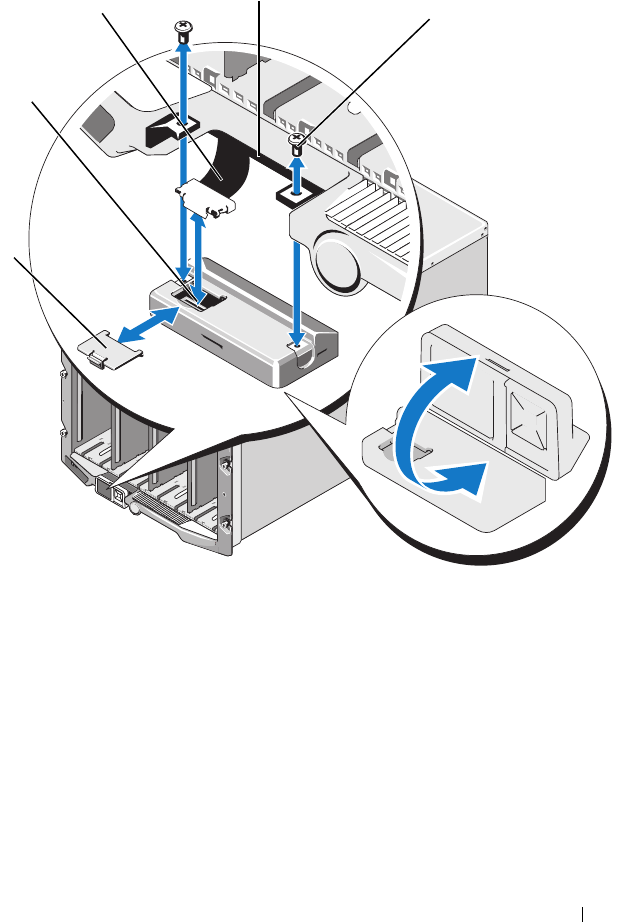
Using the LCD Panel Interface 429
Figure C-1. Removing and Installing the LCD Module
1 cable cover 2 LCD module
3 ribbon cable 4 hinges (2)
5 screws (2)
1
2
3
4
5

430 Using the LCD Panel Interface
Symptom Issue Recovery Action
Alert screen message CMC
Not Responding and
LED is blinking amber
Loss of communication
from CMC to the LCD
front panel
Check that the CMC is
booting; then, reset the
CMC using GUI or
RACADM commands.
Alert screen message CMC
Not Responding and
LED is solid amber or is
off
LCD front panel stuck in
boot block during a CMC
failover
Disconnect and reconnect
the front panel circuit board
to the I/O panel cable from
front panel. Reset the CMC
using GUI or RACADM
commands.
LED blinks amber or is
blank
The LCD to front panel
circuit board cable is not
connected properly or is
faulty; or the front panel is
faulty
Review the hardware log
using the GUI or RACADM
commands. Look for a
message that states:
Control Panel TFT
Cable: Cable sensor
for Control Panel,
configuration error
was asserted
Replace the front panel.
Screen text is scrambled Defective LCD screen Replace the front panel.
LCD screen message No
CMC Found
No CMC is present in the
chassis
Insert a CMC into the
chassis or replace existing
CMC if present and
nonfunctional.

Using the LCD Panel Interface 431
Front Panel LCD Messages
This section contains two subsections that list error and status information
that is displayed on the front panel LCD.
Error messages on the LCD have a format that is similar to the System Event
Log (SEL) viewed from the CLI or Web interface. The format is as follows:
<Severity> <Sensor Name>: <Sensor Type> sensor for
<Entity>, <Description of event>
The tables in the error section list the error and warning messages that are
displayed on the various LCD screens and the possible cause of the message.
Text enclosed in angled brackets (< >) indicates that the text may vary.
Status information on the LCD includes descriptive information about the
modules in the chassis. The tables in this section describe the information
that is displayed for each component.
Blank LCD and LED off The front panel circuit
board cable or the I/O
panel cable are not
connected properly; or one
or both are faulty.
Review the hardware log
using the GUI or RACADM
commands. Look for
messages that state:
Control Panel FPC
Cable: Cable sensor
for Control Panel,
configuration error
was asserted
Control Panel I/O
Cable: Cable sensor
for Control Panel,
configuration error
was asserted
Check that the cables are
connected properly.
Symptom Issue Recovery Action

432 Using the LCD Panel Interface
LCD Error Messages
Table C-2. CMC Status Screens
Severity Message Cause
Critical CMC <number> Battery: Battery
sensor for CMC, failed was
asserted
CMC CMOS battery is missing or
no voltage.
Critical CMC <number> CPU Temp:
Temperature sensor for CMC,
failure event
CMC CPU temperature exceeded
the critical threshold.
Critical CMC <number> Ambient Temp:
Temperature sensor for CMC,
failure event
CMC Ambient temperature
exceeded the critical threshold.
Warning Chassis FW Mismatch: Version
Change sensor for Chassis,
firmware or software
incompatibility (System BIOS in
slot XX with CMC) was asserted.
Possible loss of functionally or
features due to incompatible
software versions.
Warning Chassis FW Mismatch: Version
Change sensor for Chassis,
firmware or software
incompatibility (iDRAC in slot XX
with CMC) was asserted.
Possible loss of functionally or
features due to incompatible
software versions.
Table C-3. Enclosure/Chassis Status Screen
Severity Message Cause
Critical Chassis Fan <number> Presence:
Fan sensor for Chassis Fan, device
removed was asserted
This fan is required for proper
cooling of the enclosure/chassis.
Warning Power Supply Redundancy: PS
Redundancy sensor for Power
Supply, redundancy degraded was
asserted
One or more PSU have failed or
removed and the system can no
longer support full PSU
redundancy.

Using the LCD Panel Interface 433
Critical Power Supply Redundancy: PS
Redundancy sensor for Power
Supply, redundancy lost was
asserted
One or more PSU have failed or
removed and the system is no
longer redundant.
Critical Power Supply Redundancy: PS
Redundancy sensor for Power
Supply, non-redundant:
insufficient resources
One or more PSU have failed or
removed and the system lacks
sufficient power to maintain
normal operations. This could
cause servers to power down.
Critical Control Panel Temp: Temperature
sensor for Control Panel, failure
event
Chassis/Enclosure temperature
exceeded the critical threshold.
Critical CMC <number> Standalone:
Micro Controller sensor for CMC,
non-redundant was asserted
CMC no longer redundant.
NOTE: This will only show if the
standby CMC was removed or has
failed.
Critical Chassis Eventlog CEL: Event Log
sensor for Chassis Eventlog, all
event logging disabled was asserted
The CMC cannot log events.
Critical Chassis Eventlog CEL: Event Log
sensor for Chassis Eventlog, log
full was asserted
Chassis device detects that only
one entry can be added to the CEL
before it is full.
Warning Chassis Eventlog CEL: Event Log
sensor for Chassis Eventlog, log
almost full was asserted
Chassis event log is 75% full.
Table C-4. Fan Status Screens
Severity Message Cause
Critical Chassis Fan <number> Status:
Fan sensor for Chassis Fan, failure
event
The speed of the specified fan is
not sufficient to provide enough
cooling to the system.
Table C-3. Enclosure/Chassis Status Screen (continued)
Severity Message Cause

434 Using the LCD Panel Interface
Table C-5. IOM Status Screens
Severity Message Cause
Warning I/O Module <number> Status:
Module sensor for I/O Module,
transition to non-critical from OK
was asserted
The IO module was good, but now
having fabric mismatch or link
tuning mismatch.
Critical I/O Module <number> Status:
Module sensor for I/O Module,
transition to critical from less
severe was asserted
The I/O module has a fault. The
same error can also happen if the
I/O module is thermal-tripped.
Table C-6. iKVM Status Screen
Severity Message Cause
Warning Local KVM Health: Module sensor
for Local KVM, transition to non-
critical from OK was asserted
Minor failure, such as corrupted
firmware.
Critical Local KVM Health: Module sensor
for Local KVM, transition to
critical from less severe was
asserted
USB host enumeration failure or
OSCAR failure.
Non-
Recoverable
Local KVM Health: Module sensor
for Local KVM, transition to non-
recoverable was asserted
Serial RIP failure or USB host chip
failure.
Table C-7. PSU Status Screens
Severity Message Cause
Critical Power Supply PSU <number>:
Power Supply sensor for Power
Supply, failure was asserted
The PSU has failed.
Critical Power Supply PSU <number>:
Power Supply sensor for Power
Supply, input lost was asserted
Loss of AC power or AC cord
unplugged.

Using the LCD Panel Interface 435
Table C-8. Server Status Screen
Severity Message Cause
Warning System Board Ambient Temp:
Temperature sensor for System
Board, warning event
Server Ambient temperature
crossed a warning threshold.
Critical System Board Ambient Temp:
Temperature sensor for System
Board, failure event
Server Ambient temperature
crossed a failing threshold.
Critical System Board CMOS Battery:
Battery sensor for System Board,
failed was asserted
CMOS battery is not present or
has no voltage.
Warning System Board System Level:
Current sensor for System Board,
warning event
Current crossed a warning
threshold.
Critical System Board System Level:
Current sensor for System Board,
failure event
Current crossed a failing threshold.
Critical CPU <number> <voltage sensor
name>: Voltage sensor for CPU
<number>, state asserted was
asserted
Voltage out of range.
Critical System Board <voltage sensor
name>: Voltage sensor for System
Board, state asserted was asserted
Voltage out of range.
Critical CPU <number> <voltage sensor
name>: Voltage sensor for CPU
<number>, state asserted was
asserted
Voltage out of range.
Critical CPU<number> Status: Processor
sensor for CPU<number>, IERR
was asserted
CPU failure.
Critical CPU<number> Status: Processor
sensor for CPU<number>,
thermal tripped was asserted
CPU overheated.

436 Using the LCD Panel Interface
Critical CPU<number> Status: Processor
sensor for CPU<number>,
configuration error was asserted
Incorrect processor type or in
wrong location.
Critical CPU<number> Status: Processor
sensor for CPU<number>,
presence was de-asserted
Required CPU is missing or not
present.
Critical System Board Video Riser: Module
sensor for System Board, device
removed was asserted
Required module was removed.
Critical Mezz B <slot number> Status:
Add-in Card sensor for Mezz B
<slot number>, install error was
asserted
Incorrect Mezzanine card installed
for I/O fabric.
Critical Mezz C <slot number> Status:
Add-in Card sensor for Mezz C
<slot number>, install error was
asserted
Incorrect Mezzanine card installed
for I/O fabric.
Critical Backplane Drive <number>:
Drive Slot sensor for Backplane,
drive removed
Storage Drive was removed.
Critical Backplane Drive <number>:
Drive Slot sensor for Backplane,
drive fault was asserted
Storage Drive failed.
Critical System Board PFault Fail Safe:
Voltage sensor for System Board,
state asserted was asserted
This event is generated when the
system board voltages are not at
normal levels.
Critical System Board OS Watchdog:
Watchdog sensor for System
Board, timer expired was asserted
The iDRAC watchdog timer
expires and no action is set.
Critical System Board OS Watchdog:
Watchdog sensor for System
Board, reboot was asserted
The iDRAC watchdog detected
that the system has crashed (timer
expired because no response was
received from Host) and the action
is set to reboot.
Table C-8. Server Status Screen (continued)
Severity Message Cause

Using the LCD Panel Interface 437
Critical System Board OS Watchdog:
Watchdog sensor for System
Board, power off was asserted
The iDRAC watchdog detected
that the system has crashed (timer
expired because no response was
received from Host) and the action
is set to power off.
Critical System Board OS Watchdog:
Watchdog sensor for System
Board, power cycle was asserted
The iDRAC watchdog detected
that the system has crashed (timer
expired because no response was
received from Host) and the action
is set to power cycle.
Critical System Board SEL: Event Log
sensor for System Board, log full
was asserted
The SEL device detects that only
one entry can be added to the SEL
before it is full.
Warning ECC Corr Err: Memory sensor,
correctable ECC (<DIMM
Location>) was asserted
Correctable ECC errors reach a
critical rate.
Critical ECC Uncorr Err: Memory sensor,
uncorrectable ECC (<DIMM
Location>) was asserted
An uncorrectable ECC error was
detected.
Critical I/O Channel Chk: Critical Event
sensor, I/O channel check NMI was
asserted
A critical interrupt is generated in
the I/O Channel.
Critical PCI Parity Err: Critical Event
sensor, PCI PERR was asserted
Parity error was detected on the
PCI bus.
Critical PCI System Err: Critical Event
sensor, PCI SERR (<Slot number
or PCI Device ID>) was asserted
PCI error detected by device.
Critical SBE Log Disabled: Event Log
sensor, correctable memory error
logging disabled was asserted
Single bit error logging is disable
when too many SBE get logged.
Critical Logging Disabled: Event Log
sensor, all event logging disabled
was asserted
All error logging is disabled.
Table C-8. Server Status Screen (continued)
Severity Message Cause

438 Using the LCD Panel Interface
Non-
Recoverable
CPU Protocol Err: Processor
sensor, transition to non-
recoverable was asserted
The processor protocol entered a
non-recoverable state.
Non-
Recoverable
CPU Bus PERR: Processor sensor,
transition to non-recoverable was
asserted
The processor bus PERR entered a
non-recoverable state.
Non-
Recoverable
CPU Init Err: Processor sensor,
transition to non-recoverable was
asserted
The processor initialization
entered a non-recoverable state.
Non-
Recoverable
CPU Machine Chk: Processor
sensor, transition to non-
recoverable was asserted
The processor machine check
entered a non-recoverable state.
Critical Memory Spared: Memory sensor,
redundancy lost (<DIMM
Location>) was asserted
Memory spare is no longer
redundant.
Critical Memory Mirrored: Memory sensor,
redundancy lost (<DIMM
Location>) was asserted
Mirrored Memory is no longer
redundant.
Critical Memory RAID: Memory sensor,
redundancy lost (<DIMM
Location>) was asserted
RAID Memory is no longer
redundant.
Warning Memory Added: Memory sensor,
presence (<DIMM Location>)
was deasserted
Added memory module was
removed.
Warning Memory Removed: Memory sensor
presence (<DIMM Location>)
was deasserted
Memory module was removed.
Critical Memory Cfg Err: Memory sensor,
configuration error (<DIMM
Location>) was asserted
Memory configuration is incorrect
for the system.
Warning Mem Redun Gain: Memory sensor,
redundancy degraded (<DIMM
Location>) was asserted
Memory redundancy is down
graded but not lost.
Table C-8. Server Status Screen (continued)
Severity Message Cause

Using the LCD Panel Interface 439
Critical PCIE Fatal Err: Critical Event
sensor, bus fatal error was asserted
Fatal error is detected on the PCIE
bus.
Critical Chipset Err: Critical Event sensor,
PCI PERR was asserted
Chip error is detected.
Warning Mem ECC Warning: Memory
sensor, transition to non-critical
from OK (<DIMM Location>)
was asserted
Correctable ECC errors have
increased from a normal rate.
Critical Mem ECC Warning: Memory
sensor, transition to critical from
less severe (<DIMM Location>)
was asserted
Correctable ECC errors have
reached a rate.
Critical System Board POST Err: POST
sensor for System Board, POST
fatal error <additional error
information> was asserted
See Hardware Service Manual for
BIOS POST addition error
information.
Critical POST Err: POST sensor, No
memory installed
No memory detected on board
Critical POST Err: POST sensor, Memory
configuration error
Memory detected but is not
configurable
Critical POST Err: POST sensor, Unusable
memory error
Memory configured but not usable
Critical POST Err: POST sensor, Shadow
BIOS failed
System BIOS shadow failure
Critical POST Err: POST sensor, CMOS
failed
CMOS failure
Critical POST Err: POST sensor, DMA
controller failed
DMA controller failure
Critical POST Err: POST sensor, Interrupt
controller failed
Interrupt controller failure
Critical POST Err: POST sensor, Timer
refresh failed
Timer refresh failure
Table C-8. Server Status Screen (continued)
Severity Message Cause

440 Using the LCD Panel Interface
Critical POST Err: POST sensor,
Programmable interval timer error
Programmable interval timer error
Critical POST Err: POST sensor, Parity
error
Parity error
Critical POST Err: POST sensor, SIO
failed
SIO failure
Critical POST Err: POST sensor, Keyboard
controller failed
Keyboard controller failure
Critical POST Err: POST sensor, System
management interrupt
initialization failed
System Management Interrupt
initialization failure
Critical POST Err: POST sensor, BIOS
shutdown test failed
BIOS shutdown test failure
Critical POST Err: POST sensor, BIOS
POST memory test failed
BIOS POST memory test failure
Critical POST Err: POST sensor, Dell
remote access controller
configuration failed
Dell Remote Access Controller
configuration failure
Critical POST Err: POST sensor, CPU
configuration failed
CPU configuration failure
Critical POST Err: POST sensor, Incorrect
memory configuration
Incorrect memory configuration
Critical POST Err: POST sensor, POST
failure
General failure after video
Critical Hdwar version err: Version Change
sensor, hardware incompatibility
was asserted
Incompatible hardware was
detected
Critical Hdwar version err: Version Change
sensor, hardware incompatibility
(BMC firmware) was asserted
Hardware is incompatible with the
firmware
Table C-8. Server Status Screen (continued)
Severity Message Cause

Using the LCD Panel Interface 441
Critical Hdwar version err: Version Change
sensor, hardware incompatibility
(BMC firmware and CPU
mismatch) was asserted
CPU and firmware not compatible
Critical Mem Overtemp: Memory sensor,
correctable ECC <DIMM
Location> was asserted
Memory module overheating
Critical Mem Fatal SB CRC: Memory
sensor, uncorrectable ECC was
asserted
South bridge memory failed
Critical Mem Fatal NB CRC: Memory
sensor, uncorrectable ECC was
asserted
North bridge memory failed
Critical WatchDog Timer: Watchdog
sensor, reboot was asserted
Watch dog timer cause system to
reboot
Critical WatchDog Timer: Watchdog
sensor, timer expired was asserted
Watch dog timer expired but no
action taken
Warning Link Tuning: Version Change
sensor, successful software or F/W
change was deasserted
Failed to update link tuning
setting for proper NIC operation
Warning Link Tuning: Version Change
sensor, successful hardware change
<device slot number> was
deasserted
Failed to update link tuning
setting for proper NIC operation
Critical LinkT/ FlexAddr: Link Tuning
sensor, failed to program virtual
MAC address (Bus # Device #
Function #) was asserted
FlexAddress could not be
programmed for this device
Critical LinkT/ FlexAddr: Link Tuning
sensor, device option ROM failed
to support link tuning or flex
address (Mezz <location>) was
asserted
Option ROM does not support
FlexAddress or link tuning.
Table C-8. Server Status Screen (continued)
Severity Message Cause

442 Using the LCD Panel Interface
LCD Module and Server Status Information
The tables in this section describe status items that are displayed on the front
panel LCD for each type of component in the chassis.
Critical LinkT/ FlexAddr: Link Tuning
sensor, failed to get link tuning or
flex address data from
BMC/iDRAC was asserted
Failed to obtain linking tuning or
FlexAddress information from
BMC/iDRAC
Critical LinkT/ FlexAddr: Link Tuning
sensor, device option ROM failed
to support link tuning or flex
address (Mezz XX) was asserted
PCI device Option ROM for a NIC
does not support link tuning or the
FlexAddress feature.
Critical LinkT/ FlexAddr: Link Tuning
sensor, failed to program virtual
MAC address (<location>) was
asserted
BIOS failed to program virtual
MAC address on the given NIC
device.
Critical I/O Fatal Err: Fatal IO Group
sensor, fatal IO error (<location>)
Generated in association with a
CPU IERR and indicates which
device caused the CPU IERR.
Warning PCIE NonFatal Er: Non Fatal IO
Group sensor, PCIe error
(<location>)
Generated in association with a
CPU IERR.
Table C-9. CMC Status
Item Description
Name/Location Example: CMC1, CMC2
Error Messages If no error then "No Errors" is shown; otherwise error messages
are listed, critical errors first, then warnings.
IP Address Only shows on active CMC.
Firmware Version Only shows on active CMC.
Table C-8. Server Status Screen (continued)
Severity Message Cause

Using the LCD Panel Interface 443
Table C-10. Chassis/Enclosure Status
Item Description
User Define Name Example: “Dell Rack System”. This is settable via CMC CLI
or Web GUI
Error Messages If no error then "No Errors" is shown; otherwise error messages
are listed, critical errors first, then warnings.
Model Number Example "PowerEdgeM1000"
Power Consumption Current power consumption in watts
Surplus for Peak
Performance
The surplus for peak performance value is the difference
between the System Input Power Cap and the Power
Required for Peak Performance (sum of the Maximum Input
Power Allocated to Servers and the Maximum Input Power
Allocated to Chassis Infrastructure). The value for Surplus for
Peak Performance is displayed in both the watts and BTU/h
units.
Peak Power Peak power consumed in watts
Minimum Power Minimum power consumed in watts
Ambient
Temperature
Current ambient temperature in degrees Celsius
Service Tag The factory-assigned service tag
CMC redundancy
mode
Non-Redundant or Redundant
PSU redundancy
mode
Non-Redundant, AC Redundant, or DC Redundant
Table C-11. Fan Status
Item Description
Name/Location Example: Fan1, Fan2, etc.
Error Messages If no error then "No Errors" is shown; otherwise error messages
are listed, critical errors first, then warnings.
RPM Current fan speed in RPM

444 Using the LCD Panel Interface
Table C-12. PSU Status
Item Description
Name/Location Example: PSU1, PSU2, etc.
Error Messages If no error then "No Errors" is shown; otherwise error
messages are listed, critical errors first, then warnings.
Status Offline, Online, or Standby
Maximum Wattage Maximum Wattage that PSU can supply to the system
Table C-13. IOM Status
Item Description
Name/Location Example: IOM A1, IOM B1.
Error Messages If no error then "No Errors" is shown; otherwise error
messages are listed, critical errors first, then warnings.
Status Off or On
Model Model of the IOM
Fabric Type Networking type
IP address Only shows if IOM is On. Will be all zero for a pass through
type IOM.
Service Tag The factory-assigned service tag.
Table C-14. iKVM Status
Item Description
Name iKVM
Error Messages If no error then "No Errors" is shown; otherwise error
messages are listed, critical errors first, then warnings.
Status Off or On
Model/Manufacture A description of the iKVM model.
Service Tag The factory-assigned service tag.

Using the LCD Panel Interface 445
Part Number The manufacturer part number.
Firmware Version The iKVM firmware version.
Table C-15. Server Status
Item Description
Name/Location Example: Server 1, Server 2.
Error Messages If no error then "No Errors" is shown; otherwise error messages
are listed, critical errors first, then warnings.
Slot Name CMC slot name. Example SLOT-01. Note: this is settable via
CMC CLI or Web GUI.
Name User settable name of the server. Settable via server BIOS,
iDRAC CLI or Web GUI. Displays if iDRAC finished booting,
or will display iDRAC booting messages.
Model Number Displays if iDRAC finished booting.
Service Tag Displays if iDRAC finished booting.
iDRAC IP Address Displays if iDRAC finished booting. If iDRAC is set for DHCP
and has not obtained IP, will display Acquiring.
Last Post Code Displays the most recently posted code delivered by the server
BIOS.
BIOS Version Displays if iDRAC finished booting.
iDRAC Firmware
Version
Displays if iDRAC finished booting.
FlexAddress enabled
on Fabrics:
<Fabric>
Displays if feature is installed. Lists fabrics that are
FlexAddress-enabled for this server (for example, A, B, C).
Table C-14. iKVM Status (continued)
Item Description

446 Using the LCD Panel Interface

Glossary 447
Glossary
Active Directory
Active Directory is a centralized and standardized system that automates network
management of user data, security, and distributed resources, and enables
interoperation with other directories. Active Directory is designed especially for
distributed networking environments.
ARP
Address resolution protocol, a method for finding a host’s Ethernet address from
its Internet address.
ASCII
American Standard Code for Information Interchange, a code representation used
for displaying or printing letters, numbers, and other characters.
blade
A self-contained server designed for high density racks.
BIOS
Basic input/output system, the part of system software that provides the lowest-
level interface to peripheral devices and which controls the first stage of the system
boot process, including installation of the operating system into memory.
CMC
The Dell Chassis Management Controller, providing
remote management
capabilities and power control functions for Dell PowerEdge™ systems.
bus
A set of conductors connecting the various functional units in a computer. Busses
are named by the type of data they carry, such as data bus, address bus, or PCI bus.
CA
A certificate authority (CA) is a business entity that is recognized in the IT
industry for meeting high standards of reliable screening, identification, and other
important security criteria. Examples of CAs include Thawte and VeriSign. After
the CA receives your CSR, they review and verify the information the CSR
contains. If the applicant meets the CA’s security standards, the CA issues a

448 Glossary
certificate to the applicant that uniquely identifies that applicant for transactions
over networks and on the Internet.
CD
Compact disc
Certificate Signing Request (CSR)
A digital request to a certificate authority for a secure server certificate.
CLI
Command Line interface
DHCP
Dynamic host configuration protocol, a means of dynamically allocating IP
addresses to computers on a network.
DLL
Dynamic link library, a library of functions, any of which can be called when
needed by a larger program that is running in the system. The smaller functions
let the larger program communicate with a specific device such as a printer or
scanner.
DNS
Domain name system
iDRAC
The Dell Integrated Remote Access Controller, a systems management hardware
and software solution that provides remote management capabilities, crashed
system recovery, and power control functions for Dell PowerEdge systems.
delay time (OSCAR user interface)
The number of seconds before the OSCAR Main dialog box is displayed after
<Print Screen> is pressed.
extended schema
A solution used with Active Directory to determine user access to the CMC; uses
Dell-defined Active Directory objects
.

Glossary 449
FQDN
Fully qualified domain name, a domain name that specifies a module’s absolute
position in the DNS tree hierarchy. Microsoft
®
Active Directory
®
only supports
an FQDN of 64 bytes or fewer.
FSMO
Flexible single master operation, a Microsoft Active Directory domain controller
task that guarantees atomicity of an extension operation.
GB1
The uplink port on the chassis.
GMT
Greenwich Mean Time. GMT is the standard time common to every place in the
world. GMT nominally reflects the mean solar time along the prime meridian
(0 longitude) that runs through the Greenwich Observatory outside of London,
UK.
GUI
Graphical user interface, which refers to a computer display interface that uses
elements such as windows, dialog boxes, and buttons as opposed to a command
prompt interface, in which all user interaction is displayed and typed in text.
hardware log
A CMC-generated record of events relating to hardware on the chassis.
ICMP
Internet control message protocol, a way for operating systems to send error
messages.
ID
Identifier, commonly used when referring to a user identifier (user ID) or object
identifier (object ID).
iKVM
Avocent® Integrated KVM Switch Module, an optional, hot-pluggable module
to the chassis providing local access to keyboard, mouse, and video to any of
the 16 servers in the chassis, as well as the additional Dell CMC Console option
that connects to the chassis’ active CMC.

450 Glossary
IOMINF
I/O module infrastructure device.
IP
Internet Protocol. IP is the network layer for TCP/IP. IP provides packet routing,
fragmentation, and reassembly.
IPMB
Intelligent platform management bus, which is used in systems management
technology.
Kbps
Kilobits per second, a data transfer rate.
LAN
Local area network
LDAP
Lightweight directory access protocol
LED
Light-emitting diode
LOM
Local area network on motherboard
MAC
Media access control, a network sublayer between a network node and the network
physical layer.
MAC address
Media access control address, a unique address embedded in the physical
components of a NIC.
management station
A system that remotely accesses the CMC.
Mbps
Megabits per second, which is a data transfer rate.

Glossary 451
MC
Mezzanine card
Microsoft Active Directory
A centralized, standardized system that automates network management of user
data, security, and distributed resources, and enables interoperation with other
directories. Active Directory is designed especially for distributed networking
environments.
NIC
Network interface card, an adapter circuit board installed in a computer to provide
a physical connection to a network.
OID
Object identifier
OSCAR
On Screen Configuration and Reporting, a graphical user interface used for
iKVM access.
PCI
Peripheral component interconnect, a standard interface and bus technology for
connecting peripherals to a system and for communicating with those peripherals.
POST
Power-on self-test, a sequence of diagnostic tests that are run automatically by a
system when it is powered on.
RAC
Remote access controller
RAM
Random-access memory. RAM is general-purpose readable and writable memory
on systems.
RAM disk
A memory-resident program which emulates a hard drive.
ROM
Read-only memory, from which data may be read, but to which data cannot be
written.

452 Glossary
RPM
Red Hat Package Manager, a package-management system for the Red Hat
Enterprise Linux operating system. RPM manages the installation of software
packages. It is similar to an installation program.
SEL
System event log or hardware log
SMTP
Simple mail transfer protocol, used to transfer electronic mail between systems—
usually over an Ethernet.
SNMP
Simple network management protocol, designed to manage nodes on an IP
network. iDRACs are SNMP-managed devices (nodes).
SNMP trap
A notification (event) generated by the CMC that contains information about
state changes on the managed system or about potential hardware problems.
SSH
Secure Shell, a network protocol that allows data to be exchanged over a secure
channel between two computers.
SSL
Secure sockets layer, a protocol that provides secure communications over
networks for data transfers.
standard schema
A solution used with Active Directory to determine user access to the CMC; uses
Active Directory group objects only.
STK
The staking port on the chassis
TCP/IP
Transmission control protocol/Internet protocol, representing the set of standard
Ethernet protocols that includes the network layer and transport layer protocols.

Glossary 453
TFTP
Trivial file transfer protocol, a simple file transfer protocol used for downloading
boot code to diskless devices or systems.
UPS
Uninterruptible power supply
USB
Universal serial bus, a serial bus standard to interface devices.
UTC
Universal Coordinated Time.
See
GMT.
vKVM
Virtual keyboard-video-mouse console
VLAN
Virtual local area network
VNC
Virtual network computing
VT-100
Video Terminal 100, which is used by the most common terminal emulation
programs.
WAN
Wide area network

454 Glossary

Index 455
Index
A
ACI, 247
Active Directory, 185-212
adding CMC users, 198
configuring access to the
CMC, 191
configuring and managing
certificates, 130
extending schemas, 191
objects, 187
schema extensions, 186
using with standard schema, 205
adding
SNMP alerts, 286
alerts
troubleshooting, 315
Analog Console Interface, 245
C
Certificate Signing Request
(CSR)
about, 137
generating a new certificate, 138
certificates
Active Directory, 130
SSL and digital, 136
uploading a server certificate, 141
viewing a server certificate, 141
cfgAlerting, 403
CMC
configuring, 201, 208
creating a configuration file, 86
downloading firmware, 52
feature sets, 25
installing, 35
log, 303
redundant environment, 55
setting up, 35
command line console
features, 57
configuration file
creating, 86
configuring
CMC from the LCD panel, 52
CMC remote RACADM, 50
power budgeting, 52
remote RACADM, 50
SNMP alerts, 286
connect command
CMC command line
connection, 67
F
fabric management, 273
feature sets of CMC, 25
featurecard, 171

456 Index
firmware
downloading, 52
managing, 151
updating, CMC, 152
updating, iKVM, 154
updating, IOM infrastructure
device, 155
updating, Server iDRAC, 156
FlexAddress, 169
activating, 170
activation verification, 171
configuring using CLI, 174
deactivating, 173
license agreement, 180
Linux configuration, 175
troubleshooting, 176
viewing status using CLI, 174
Wake-On-LAN, 175
frequently asked questions
managing and recovering a remote
system, 165
using the CMC with Active
Directory, 212
H
hardware log, 300
hardware specifications, 28
I
I/O fabric, 273
iDRAC
recovering firmware, 157
iKVM, 245
installing CMC, 35
L
LDC panel
configuring CMC from, 52
logs
CMC, 303
hardware, 300
M
managed system
accessing through the local serial
port, 58
management station
configuring terminal
emulation, 60
MC
definition, 451
mezzanine card. See also MC
Microsoft Active
Directory, 185-212
N
network properties
configuring manually, 77
configuring using racadm, 77

Index 457
O
OSCAR, 245
P
parsing rules, 87
password
disabling, 312
reset jumper location, 314
power budgeting
configuring, 52
power conservation, 218
property database groups
cfgActiveDirectory, 410
cfgChassisPower, 413
cfgCurrentLanNetworking, 390
cfgEmailAlert, 395
cfgKVMInfo, 421
cfgLanNetworking, 387
cfgNetTuning, 400
cfgOobSnmp, 402
cfgRacSecurity, 408
cfgRacTuning, 404
cfgRemoteHosts, 391
cfgSerial, 398
cfgServerInfo, 418
cfgSessionManagement, 397
cfgStandardSchema, 412
cfgTraps, 402
cfgUserAdmin, 393
displayable characters, 385
idRacInfo, 385
proxy server, 38
R
RAC
see Remote Access
Connection, 29
RACADM
uninstalling from Linux
management station, 37
RACADM subcommands
?, 317
arp, 318
chassisaction, 319
clrraclog, 320
clrsel, 321
cmcchangeover, 321
config, 322
deploy, 324
feature, 326
featurecard, 327
fwupdate, 329
getassettag, 331
getchassisname, 332
getconfig, 332
getdcinfo, 335
getflexaddr, 337
getioinfo, 339
getkvminfo, 340
getled, 340
getmacaddress, 342
getmodinfo, 343
getniccfg, 345
getpbinfo, 346
getpminfo, 348
getraclog, 349
getractime, 350
getredundancymode, 351

458 Index
RACADM subcommands
(continued)
getsel, 352
getsensorinfo, 353
getslotname, 354
getssninfo, 354
getsvctag, 356
getsysinfo, 357
gettracelog, 359
help, 360
ifconfig, 361
racdump, 363
racreset, 366
racresetcfg, 367
serveraction, 368
setchassisname, 369
setflexaddr, 370
setled, 372
setniccfg, 373
setractime, 374
setslotname, 376
setsysinfo, 377
sslcertdownload, 378
sslcertupload, 378
sslcertview, 379
sslcsrgen, 381
sslresetcfg, 382
testemail, 383
testtrap, 384
racadm utility
configuring network
properties, 77
parsing rules, 87
subcommands, 317
Red Hat Enterprise Linux
configuring for serial console
redirection, 63
redundant environment, 55
remote access connection
(RAC), 29
remote RACADM
configuring, 50
S
Secure Sockets Layer (SSL)
about, 136
security
using SSL and digital
certificates, 136
serial console
using, 58
server certificate
uploading, 141
viewing, 141
services
configuring, 143
setting up CMC, 35
slot names
editing, 99
naming rules, 99
setting with RACADM, 376
snap-in
installing the Dell extension, 197
SNMP alerts
adding and configuring, 286


460 Index
